

Page 1

Reproduction Reference
DD1783793—P1604
4000 Series Digital Billboard
Service Manual
1. This page is for reproduction reference only and will not be included in the manual.
2. This manual is to be copied on front and back pages using 8 ½ x 11 paper.
Note: Section heading pages always start on a new page; they never start on the back of
another page.
3. Materials included in this manual at the end of each section:
• Appendix A: Daktronics Warranty
4. Use a blue window cover and a blue back.
5. Punch all pages, window cover, and back cover, along the left edge and bind with a binder.
6. Please direct questions and suggestions to Engineering Secretarial.
Page 2

Page 3

www.daktronics.com
4000 Series
Digital Billboard
DD1783793 Rev 7 – 28 July 2011
Service Manual
201 Daktronics Dr. PO Box 5128 Brookings SD, 57006
Tel 866-343-3122 Fax 605-697-4700
Page 4

DD1783793
Project 1604
Rev 7 –28 July 2011
DAKTRONICS, INC.
Copyright 2010
All rights reserved. While every precaution has been taken in the preparation of this manual, the publisher
assumes no responsibility for errors or omissions. No part of this book covered by the copyrights hereon may be
reproduced or copied in any form or by any means—graphic, electronic, or mechanical, including photocopying,
taping, or information storage and retr ieval sy ste ms—without written permission of the publisher.
Page 5

Table of Contents
Section 1: Introduction ................................................................................................................. 1
1.1 About this Manual .................................................................................................................. 1
1.2 4000 Series Digital Billboard Overview ............................................................................... 2
1.3 Spare Parts List ........................................................................................................................ 3
Section 2: Display Troubleshooting ............................................................................................ 5
Section 3: Removing Modules from the Display ........................................................................ 7
3.1 Important Note on Signal and Power Cables ...................................................................... 7
3.2 Proper Seating of SATA and Power Cables ........................................................................ 7
3.3 Rear Access Doors ................................................................................................................... 8
3.4 Remove and Reinstall a Module from the Rear of the Display ........................................ 8
3.5 Remove and Reinstall a Module from the Front of the Display ..................................... 12
3.6 Module Status Indicators ..................................................................................................... 13
3.7 Self Test a Module ................................................................................................................. 14
Section 4: Replacing Display Components ............................................................................... 15
4.1 Photocell ................................................................................................................................. 15
4.2 ProLink Router (PLR) ........................................................................................................... 16
4.3 Power Supply ........................................................................................................................ 17
4.4 Filter ........................................................................................................................................ 17
4.5 Fan ........................................................................................................................................... 18
4.6 Webcam .................................................................................................................................. 18
Section 5: Routine Maintenance ................................................................................................ 21
5.1 Inspecting a Display ............................................................................................................. 21
5.2 Restarting a Display .............................................................................................................. 21
5.3 Cleaning the Webcam Lens ................................................................................................. 22
5.4 Fan Operation ........................................................................................................................ 22
Section 6: Service Call ................................................................................................................ 23
6.1 Service Instructions ............................................................................................................... 23
Section 7: Annual Maintenance Checks .................................................................................... 25
7.1 Service Instructions ............................................................................................................... 25
7.2 Cleaning a Display Face ....................................................................................................... 27
Page 6

Section 8:
Section 9: Signal Routing ........................................................................................................... 31
Section 10: Testing the Display Ground ...................................................................................... 33
Glossary .................................................................................................................................... 35
Appendix A: Daktronics Warranty Information ............................................................................. 37
Remote Enclosure Parts List ...................................................................................... 29
10.1 Testing with a Ground Meter .............................................................................................. 33
10.2 Testing with a Multimeter ................................................................................................... 33
Page 7

S ection 1: Introduc tion
This manual provides service and maintenance information for the 4000 Series Digital Billboards. To
ensure optimal display life, take time to read and understand the information in this manual.
1.1 About this Manual
This manual is divided into ten sections:
• Introduction: Explains basic information needed to use this manual.
• Display Troubleshooting: Explains basic troubleshooting steps.
• Removing Modules from the Display: Explains the various ways of removing
modules from a display.
• Replacing Display Components: Explains how to replace display components.
• Routine Maintenance: Explains recommended guidelines for routine maintenance.
• Service Call: Explains the recommended guidelines for service calls.
• Annual Maintenance Checks: Explains the recommended guidelines for annual
maintenance checks.
• Remote Enclosure Parts List: Provides a list of part names and part numbers for the
remote enclosure
• Signal Routing: Explains the signal routing in the 4000 series displays.
• Testing the Display Ground: Explains how to test power and signal.
At the end of this manual are a glossary and appendix:
• Glossary: Defines various terms used in the manual.
• Appendix A: Daktronics Warranty and Limitation Liability: Provides information on
warranty and liability.
Introduc tion 1
Page 8
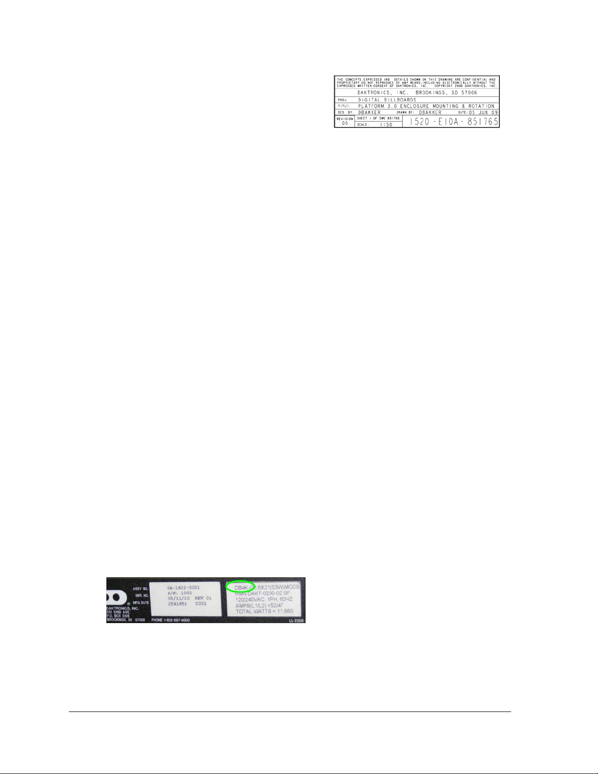
Figure 2: Display Label
Figure 1 illustrates a Daktronics drawing label.
The drawing number is located in the lowerright corner of a drawing. This manual refers to
drawings by listing the last set of digits and the
letter preceding them.
Figure 1: Daktronics Drawing Label
In the example in Figure 1, the drawing would
be referred to as Drawing A-69945.
All references to drawing numbers, appendices, figures, or other manuals are presented in
bold typeface, as shown above.
1.2 4000 S eries Digital B illboard Overview
What has Changed
• Hinged doors, capable of being lifted off the hinge
• Cabinet-mounted fans, which can be removed without tools
• Completely sealed modules
• SATA cables replace ribbon cables
• ProLink Routers replace Multi-Line Controllers
• VIP-4060 in remote enclosure
Wha t S tayed the S a me
• Cabinet is the same as 2000 and 3000 series
• Mounting plates, splice key, pick points (for lifting the display), power entry point, and
the remote enclosure are the same as the 3000 series.
Dis play L abel
Hinged doors are easily identifiable features of the 4000 series. Another way to identify the
4000 series is to check the label on the back of the display, next to the power entrance. It
should read “DB4K.” Refer to Figure 2.
2 Introduc tion
Page 9
1.3 Spare Parts List
0A-1487-6000
Assy, PLR 6050 W/ Hook Mount, 0P-1525-0001
0A-1604-4001
Assy; Mod PS, HK, Posi-lock, A-2021R, 0P-1273-0063
W-2094
Cable; SATA Plug To SATA Plug, 2', Crossover
W-2210
Harn; 142", 4 pin m mnl sealed-2pin
The following table is a generic list of spare parts found in the spare parts box. Spare parts
requirements vary for each display. For a project-specific spare parts list, refer to the spare
parts list on the inside of the spare parts box lid.
P a rt number Description
Introduc tion 3
Page 10

Page 11
S ection 2: Dis play Troubles hooting
to the ProLink Router (PLR).
The following table lists some problems that may occur while operating a display. The left column
contains a list of display problems. The right column contains a list of troubleshooting steps to help
resolve the issue. While this table does not cover all possible problems that may occur, it does cover
those that may occur most often.
4000 S eries Dis play Problem Troubleshooting Steps
Entire display is blank • Check that the display is receiving power and all
internal and external breakers are turned on. When
power is applied to the display, power supply LEDs
should turn on.
• Make sure the fiber-optic signal cable is connected
Module is blank
• Make sure the module status indicators and power
supply in the blank section are all on.
• Measure the voltage on the module power
connector to ensure a 12-v ol t out put .
• Make sure fiber connections to the ProLink Router
in the blank section are secure. Change the
connections with one another to test.
• Check the power status LEDs on the power supply
connected to the module. If a power indicator LED
is off, ensure the fuse on the power supply output
is intact.
• Check that the SATA cables to the module are
secure.
Display Troubleshooting 5
Page 12

Page 13
S ection 3: R emoving Modules from the Display
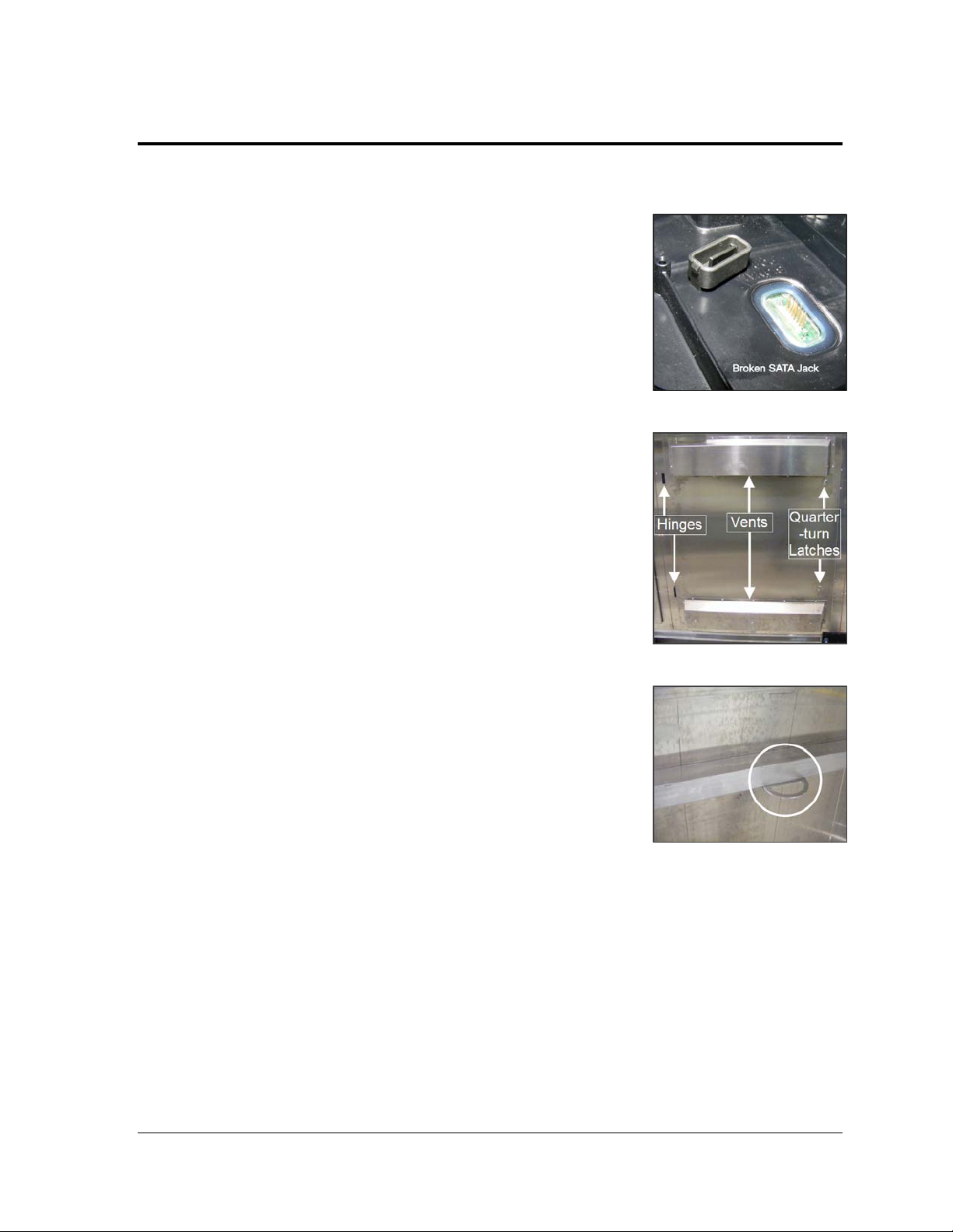
3.1 Important Note on S ignal and Power Cables
The signal and power cables connected to the modules are not
designed to be used as lanyards to hold the modules in place
when unlatched from the display face.
When performing maintenance on the display face,
Daktronics recommends removing the modules completely
from the display face to avoid possible damage.
If module removal is not possible, use the safety lanyards —
provided in the spare parts box or installation kit — to hang
modules from the display face. Refer to Figure 3 for an
example of module damage caused by using a SATA cable as
a lanyard.
3.2 Proper S eating of SATA and Power
Cables
SATA Cables
To install a SATA cable and ensure it is seated properly:
1. Align the SATA cable jack over the SATA jack on the
module.
2. Insert one end of the SATA cable jack into the SATA
jack on the module with a slight forward force..
3. Rotate the other end of the SATA cable jack into the
SATA jack on the module and press firmly until the
cable jack clicks into place and the gasket is not
visible.
Power Cables
To install a Power jack cable and ensure it is seated properly:
Figure 3: Broken SATA Jack
Figure 4: Rear Access Door
Figure 5: Door Lanyard Ring
1. Align the power cable jack over the power jack on the module.
2. Insert one end of the power cable jack into the power jack on the module.
Note: Do not squeeze the clips on the end of the cable jack when connecting.
3. Rotate the other end of the power cable jack into the power jack on the module and
press firmly until the cable jack clicks into place and the gasket is compressed.
R emoving Modules from the Display 7
Page 14

3.3 Rear Acces s Doors
Required tools: Flat head screwdriver
The 4000 series digital billboards have hinged doors that are secured with two quarter-turn
latches. If the doors are obstructed, they can be lifted off the hinges for easy access. Refer to
Figure 4.
Note: If you remove a door and find there is no safe place to put it, use a safety lanyard to
keep the door from falling. Attach the lanyard to the door lanyard ring, and attach the other
end to a secure part of the display. Refer to Figure 5.
To access the back of the display:
1. With a flat head screwdriver, turn the quarter-turn latches counterclockwise.
2. If the door is obstructed, lift the door off the hinges.
a. Attach the safety lanyard to the door lanyard hook to prevent damage.
b. Pull the bottom of the display door away from the back of the display.
c. Carefully place the access door out of the way.
3.4 R emove and R eins tall a Module from the R ear of the Display
Required tools: 1/8" hex wrench
Figure 6: Module and Installed Module
If the module is unobstructed by display components, follow the procedures below. If a
display component is obstructing access to a module, refer to the display-specific manual for
procedures on removing display components to access modules.
Refer to Figure 6 for module terminology used in this section.
8 Removing Modules from the Dis play
Page 15

1. Use a safety lanyard. Refer to Figure 7 when performing steps 1a-1c.
a. Attach one end of the safety lanyard
to a lanyard attachment ring on the
top of the module.
b. Feed the lanyard over a wire rod, or
through a nearby upright. Do not
anchor the lanyard to another
module.
c. Attach the other end of the safety
lanyard to the lanyard attachment
ring on the bottom of the module.
2. Disconnect the signal cables and power
cable.
3. With a
1
/8" hex wrench, turn the top and
bottom latch releases approximately a
quarter turn clockwise to disengage the
module latches.
Note: Always maintain a firm grip on
the module as you carefully remove the
module from the face sheet of the
display.
4. Rotate the module in a way that allows
you to guide it through the frame
opening without catching the louvers or
LEDs on the cabinet. Refer to Figure 8
and Figure 9 for examples of proper and
improper removal of modules.
Figure 7: Attach Safety Lanyard to Module
Figure 8: Proper Module Removal
5. To reinstall a module, rotate and
carefully guide the module through the
opening.
Note: To ensure proper alignment, the
word “top” is printed on the back of the
Figure 9: Improper Module Removal
module, in the upper-left and upperright corners. In addition, if the module
is upside down, the precision alignment pegs will bind on the facesheet.
6. Once the module is through the opening, align the module with the facesheet so the
gravity load pegs fit in the gravity load peg holes. Refer to Figure 10. Ensure the
lanyard or cables are not pinched between the module and the display.
R emoving Modules from the Display 9
Page 16

7. Once the module is in place, use the bottom
module lanyard rings or the lanyard to pull the
module tight against the facesheet. This is to
ensure the module latches clear the facesheet
when engaging the latches.
Note: Use care when engaging the module latches.
It is possible to damage the module latches if they
do not clear the facesheet.
8. With the
1
/8" hex wrench, turn the bottom latch
release approximately a quarter turn counterclockwise to engage the bottom latch. Verify the
latches clear the facesheet.
9. Repeat Step 8 to secure the top latch.
10. Connect signal cables and the power cable. Verify
the cables are properly seated.
11. Remove the module safety lanyard and return it to
the parts box/installation kit.
Note: Sometimes it may be necessary to remove
the module beside, above, or below in order to
access the target module. For example, you may
need to remove a module from the top-most
section of the display. In this case, you may need
to remove the module directly below the top-most
module, and pull the top-most module through
the lower opening.
R emove a Module behind a P ower S upply
Required tools: Phillips screwdriver, 5/16" nut driver
Figure 10: Gravity Load Pegs
Figure 11: Power Supply
Refer to Figure 13 for an example of the power supply.
1. Turn off power to the display.
2. With a Phillips screwdriver, remove the two screws that hold the cover to the power
supply.
3. Disconnect all power and signal cables from the power supply.
4. With a
5
/16" nut driver, remove the Tek screw below the finger tab. Refer to Figure 13
for Tek screw and finger tab location.
10 R emoving Modules from the Display
Page 17

Figure 13: Term Panel
5. Pull the finger tab to disengage the power supply from the upright, and then lift the
power supply up and away from the hook
mounts.
6. Gently set the power supply assembly down.
7. Follow the Module Removal procedure above
to remove and replace a module.
8. Once the module is replaced, reverse Steps 1-5
of this section to reinstall the power supply.
9. Turn on power to the display.
Figure 12: PLR Enclosure
R emove a Module behind a ProL ink R outer (PLR)
Required tools: Phillips screwdriver, 5/16" nut driver
Refer to Figure 14 for an example of the PLR.
1. Use a Phillips
screwdriver to
remove the PLR
enclosure cover.
2. Disconnect all power,
signal, and fiber
cables from the PLR.
3. Use a Phillips
screwdriver to
remove the top two
screws of the PLR
enclosure.
4. Use the nut driver to remove the bottom Tek screw (behind the enclosure).
5. Gently set the PLR enclosure assembly down.
6. Follow the Module Removal procedure above to remove and replace a module.
7. Once the module is replaced, reverse Steps 1-4 of this section to reinstall the PLR
enclosure assembly.
R emove a Module behind a Termination Panel
1. Turn off power to the display.
R emoving Modules from the Display 11
Page 18

2. Turn the two wing nuts at the top of the panel to unlatch the term panel. Refer to Figure
15
3. Pull back on the top of the term panel. If
necessary, you can pull the term panel off the
lower hinges, similar to the hinged doors.
4. Follow the Module Removal procedure above to
remove and replace a module.
5. Once the module is replaced, return the term
panel to its upright position and tighten the
quarter-turn wing nuts.
6. Turn on power to the display.
3.5 Remove and R eins tall a Module
from the Front of the Dis play
Required tools: 1/8" hex wrench, safety lanyard (if
necessary)
4000 series digital billboards are designed to be
accessed from the rear. However, some situations
may require removal of modules or components from
the front. If this is the case, a lift or bucket truck will
be needed to access the display from the front.
1. With one hand on the module face, insert the
1
/8" hex wrench in the access holes. Refer to
Figure 16 for the location of the access holes.
2. Turn the top and bottom latch releases
approximately a quarter turn counterclockwise.
Figure 14: Front Access
Figure 15: Safety Lanyard Attached to
Module Lanyard Attachment Rings
3. Pull the module from the display just far
enough to reach around to the back of the
module. Disconnect the power and signal
cables from the back of the module.
Figure 16: Safety Lanyard Secured to
nearby Wire Rod in Display
4. Gently set the module down on a clean and
dry surface.
a. If there is no place to set the module down, use a safety lanyard to hang the
module from the display. Attach the safety lanyard in a way that takes up slack
on the lanyard. Refer to Figure 17, Figure 18, and Figure 19 for examples.
Note: When resting the module against the display face, ensure the gravity load
pegs do not damage LEDs on the display face.
12 R emoving Modules from the Display
Page 19

5. To reinstall the module, ensure the module is properly aligned with its location in the
continuously, not blinking
ports bad signal
ports good signal
ports bad signal
Both ports good signal
display.
6. Reattach signal and power cables. Ensure no cables are hanging between the display
and the module.
7. Insert the module. Place your hand on the
module to keep it in place.
8. Firmly push in the lower half of the module to
ensure the module latches clear the face sheet.
With the
1
/8" hex wrench, turn the bottom latch
release approximately a quarter turn clockwise.
9. Repeat Step 8 to secure the top latches.
10. Gently pull the module to verify that it is
properly seated.
Note: If the module is not latched properly, the
springs on the back of the module will force the
module out.
3.6 Module S tatus Indic ators
Figure 17: Module Safety Lanyard
Prevents Module from Falling
The 4000 series module has two status indicators that
can be seen from the back of the module, one above each SATA jack. Refer to Figure 20.
Operation Modes
Under normal operation, module indicator LEDs (one on each side on the back of the
module) should flash once every two seconds. The table below lists situations in which the
status indicators will change.
Note: When troubleshooting, it is important to know that it will take up to eight seconds to
change modes.
S tatus Indic ators Problem
Both status indicators are on
Both status indicators are off No power, power hardware problem, or micro will not program
Ten pulses per second Bootstrap active and bad signal being received by jack – Both
Five pulses per second Bootstrap active and good signal being received by jack – Both
One pulse per second User program active and bad signal being received by jack – Both
Critical hardware problem, input power good
R emoving Modules from the Display 13
One pulse per four seconds User program active and good signal being received by jack –
Page 20

3.7 Self Tes t a Module
1. If a module is blank and it has power supplied to it, you can connect it for a self-test.
Attach a working SATA cable to Ports A and B, power cycle the module to run the selftest.
2. Observe the module test. The module should play red,
green, blue, white, and then a double-digit number. It
will continue to cycle through this pattern until you
stop it either by disconnecting power or the SATA
cable.
3. If the module does not display this pattern, check the
power indicator lights to verify it is receiving the
proper power (12 volts). If the power is correct, try a
known SATA cable to be sure, it is not a SATA cable
problem. If the problem persists, replace the module.
Figure 18: Self Test
14 R emoving Modules from the Display
Page 21

S ection 4: R eplacing Display C omponents
This section provides information on removing and replacing display components.
4.1 Photocell
Required tools: Wrench, utility knife, cable ties
A 25' cable is attached to the replacement photocell.
1. Unplug the old photocell cable from the remote
enclosure.
2. Cut any cable ties that hold the photocell cable in
place along the back of the display.
3. Use a wrench to remove the two attachment nuts
and bolts that hold the old photocell to the
mounting bracket. Refer to Figure 21.
4. Use the two attachment nuts and bolts to install the
new photocell in place of the old photocell. Refer to
Figure 20 and Figure 21 for mounting method
reference. Ensure the arrow on top of the photocell
is pointing the same direction as the display face.
Note: The photocell must be installed right side up
on the mounting bracket. If installed upside down
or sideways, the ambient light readings will be
inaccurate, thus causing display brightness to be
inaccurate.
5. Route the 25' cable from the photocell assembly to
the connection in the remote enclosure. If needed,
attach the extension cable (located in the spare
parts box).
6. Using cable ties, attach the photocell cable to the
cable tie anchor points along the back of the
display.
Figure 19: Attachment Nuts and Bolts
Figure 20: Left Side Mounting
Tes t
1. Test the photocell by covering all sensor windows
(front, back, and bottom) with a heavy piece of fabric to
dim the display. It may take a minute or two for the
display to dim.
R eplacing Dis play C omponents 15
Figure 21: Right Side Mounting
Page 22

4.2 ProLink R outer (PLR )
Required tools: Phillips screwdriver
Refer to Figure 24 for an example of the PLR.
1. Access the interior of the display. Refer to
Section 3.2.
2. With a Phillips screwdriver, loosen the two
screws on the PLR enclosure cover.
3. Slide the cover to the right to remove the PLR
enclosure cover.
4. Disconnect all power and signal cables from
the PLR. Refer to Figure 25.
5. Use a Phillips screwdriver to remove the old
PLR from the PLR enclosure.
6. Install the new PLR.
Figure 22: PLR Enc losure
7. Connect the cables to the new PLR. Verify the
cables are properly seated.
8. Reinstall the PLR enclosure cover.
S elf Tes t
1. Connect a duplex fiber cable to Fiber Ports A and
B. Refer to Figure 26 and Figure 27.
2. Connect a SATA cable to SATA ports A and B.
3. Connect the power cable to the PLR to start the
self-test.
This test may take up to 90 seconds to complete.
When the PLR has successfully sent and received data
through each of the connected ports, the letters
“P.A.S.” will appear on the seven-segment display.
• If the PLR detects a problem, the letters
“E.r.r.” will appear on the seven-segment
display and then it will show the two ports
that it detected the problem from (e.g. F01,
F02 for the fiber ports or F05, F06 for the
SATA ports).
Figure 23: PLR
Figure 24: PLR Components
16 Replacing Dis play C omponents
Page 23

• If an error is displayed, use a known good cable on those ports and run the test a
Display Size
Filter Quantity
20' x 60'
32
14' x 48'
26
12' x 48'
26
14' x 28'
16
21' x 21'
18
11' x 22'
12
10'6" x 36"
10
10' x 30'
8
10' x 20'
6
second time to see if it was the cable causing the error.
• If it continues to show an error, replace the PLR.
4.3 Power S upply
Required tools: Phillips screwdriver, 5/16" nut driver
Refer to Figure 28 for an example of the power supply.
1. Turn off power to the display.
2. Access the interior of the display.
Refer to Section 3.2.
3. Use a Phillips screwdriver to remove the shroud
4. Disconnect all power and signal cables from the
5. Use a
6. Pull the finger tab to disengage the power supply,
7. Reverse Steps 1-5 to replace the power supply.
8. Turn on power to the display.
4.4 Filter
Filters should be checked yearly, except for sites that have
been designated to be checked every six months. Refer to
the table below for filter quantities by display size.
that covers the power supply cables and fuses.
power supply.
5
/16" nut driver to remove the Tek screw
below the finger tab.
and then lift the power supply off the hook mount.
Figure 25: PLR Self Test
Figure 26: Power Supply
R eplacing Dis play C omponents 17
Page 24

To replace a filter in the display:
1. Depress the filter release to lower the filter door. Refer to Figure 27.
2. Remove the filter.
3. Install the new filter.
4. Close the filter tray. Verify the filter release is in place.
4.5 Fan
Required tools: Utility knife, cable tie
1. Access the interior of the display. Refer to Section 3.2.
2. To remove a fan, first locate its 4-pin to 6-pin fan
3. Disconnect the fan harness.
harness. It should be zip-tied to the wire rod with
other cables. Refer to Figure 28.
4. To remove the fan power cable, cut the cable tie from
the wire rod. Take care not to cut through any cables.
5. Once power is removed from the fan, compress and
hold the finger guard against the fan body. Refer to
Figure 31.
6. Rotate the fan until the hook can be lifted up. Remove
the fan from the display.
7. Install the new fan.
8. Connect the fan to the fan harness. Verify the fan
works.
9. Use a new cable tie to reattach the cables to the wire
rod.
4.6 Webcam
Required tools: 1-1/16" socket wrench
R etrac t the W ebcam Ar m
Figure 27: Filter Release
Figure 28: Cable tie and Fan Harness
Figure 29: Fan
1. Disconnect webcam power and signal cables from the
display.
18 Replacing Dis play C omponents
Page 25

2. Use a 1-
1
/16" socket wrench to remove the three short bolts from the top of the elbow
assembly. Refer to Figure 32.
Note: Do not remove the long bolts.
3. Use the handle to pivot the webcam arm to the catwalk.
Note: Ensure that the power and signal cables do not get pinched when pivoting the
webcam arm.
R emove and R eplace the Webcam
1. Loosen the four saddle bolts. Lift the webcam and tube
saddle from the arm. Refer to Figure 31.
2. Pull the cables through the webcam arm.
3. Route the new cables through the webcam arm.
Note: Ensure there is enough excess cable to allow the
webcam to pivot if needed.
4. Use the four saddle bolts to mount the new webcam
and tube saddle on the arm.
5. Return the webcam arm to the original position when
done servicing the webcam.
6. Reinsert and tighten the three short bolts on the elbow
assembly.
7. Work with the NOC to verify the webcam is
functioning and focused properly.
Figure 30: Webcam Arm
Figure 31: Webcam
R eplacing Dis play C omponents 19
Page 26

Page 27

S ection 5: R outine Maintenance
5.1 Inspecting a Display
When performing maintenance on a display, check for the following items:
• Inspect for modules protruding from the display face. If a module is protruding from
the display, press the module in and latch the module. If the module will not latch,
the module may need replacement.
• Inspect for dirty filters in the display and the control enclosure.
• Inspect for water in the display. If water is found, attempt to locate the source of
water intrusion.
• Ensure the fans are working properly.
• Ensure there is not standing water in the spare parts box.
• Ensure the gasket is on the spare parts box.
• Call the NOC at 1-877-325-4357 if any of the issues are found.
5.2 R es tarting a Display
Occasionally, it may be necessary to restart a display. To restart a display:
1. Shut down all control equipment in the remote enclosure.
2. Turn off the Uninterruptible Power Supply (UPS). Not turning off the UPS will delay
sign restart.
3. Turn off all breakers in the main distribution panel inside the display. Refer to the
display-specific system riser to locate the distribution panel. Typically, there is one
breaker panel per display section.
4. Turn off site power.
5. Turn on site power.
6. Turn on all breakers in the main distribution panel inside the display.
7. Restart the UPS.
8. Restart all of the control equipment in the remote enclosure.
R outine Maintenance 21
Page 28

5.3 Cleaning the Webcam L ens
Clean the camera lens on every visit. Use the retractable webcam arm to pull the webcam
close enough to clean the lens.
1. To move the retractable arm, use a 1-
wrench to remove the three short bolts from the top of
the elbow assembly. Refer to Figure 34.
Note: Do not remove the long bolts.
2. Use the handle to pivot the webcam arm to the catwalk.
3. Verify the power and signal cables do not get pinched
when pivoting the webcam arm.
4. Carefully clean the webcam lens with a lens-cleaning
wipe or with a clean rag and a glass cleaner.
5. Return the webcam arm to the original position when done servicing the webcam.
6. Replace and tighten the three short bolts.
Note: If you think the lens may be out of focus after the cleaning, call the NOC at 1-877-
325-4357 to ensure the webcam is focused and the image is clear.
1
/16" socket
Figure 32: Webcam Arm Pivot
5.4 Fan Operation
1. Regularly check fan function. To do so, hold your hand or a piece of light paper above
the fan to detect air movement.
2. Check connections to the power supply. Make sure the fuse is not blown. If the fuse is
not blown, replace the fan. If the fuse is blown, replace it and check fans again.
3. If the fan does not turn or does not operate smoothly, replace it. After replacing 10
percent of the fans, Daktronics recommends replacing all cooling fans to reduce
associated maintenance costs that may incur with increased heat buildup from fan
failure.
22 R outine Maintenance
Page 29

S ection 6: S ervice Call
At every service call, perform the following service and maintenance checks.
Required tools: Digital camera, to provide Daktronics with evidence of display damage,
water intrusion, or other issues.
6.1 Service Instructions
When arriving on site, contact Daktronics Dispatch at 1-866-325-8425 and selecting #1 before
service to announce you are on site. If immediate technical assistance is needed, ask to be
transferred to the technical help desk. If no assistance is needed, proceed with display
service.
S ervice Is sue
1. Correct the service issue.
S truc ture
1. Inspect the structure, ladder, and catwalks for structural integrity.
Dis play C abinet
1. Check the entire display cabinet for holes, gaps, and other issues. Fill any gaps or holes
with silicone approved for use on aluminum.
2. Ensure the doors are latched.
Wa ter Intrus ion Ins pec tion
1. Check section splices for water trails. Follow the water trail to its source and silicone as
needed.
2. Check the inside of the display at several locations for evidence of water intrusion,
corrosion, or water stains. Include the cabinet, modules, power supplies, and PLRs in the
inspection. Photograph any evidence of water intrusion.
Service Call 23
Page 30

Modules
1. Ensure all modules are seated properly. Work with the NOC to run a red test pattern.
View the display from one end and look down the face of the display to inspect for
modules that are sticking out.
2. Check for stuck pixels, bent LEDs, broken louvers, and other issues that may affect the
display image quality.
3. Remove any loose modules and inspect them for stripped gears, broken latches, etc.
R emote E nclos ure
1. Inspect the remote enclosure for overall integrity.
2. Check the remote enclosure for signs of water intrusion, especially at entry locations.
3. If the remote enclosure is equipped with a/c, check the filter. Remove and wash the filter
if it is dirty. Allow the filter to dry before reinserting it.
4. Visually inspect the electronics and cabling in the remote enclosure. Look for worn
cables, connectors, dust in the computer or VIP-4060 fans, corrosion, etc.
5. Verify the key to the spare parts box is in the remote enclosure.
Spare Parts B ox
1. Inspect the spare parts box for signs of water intrusion.
2. Inventory all spare parts in the box. Lock the spare parts box and place the keys in the
remote enclosure.
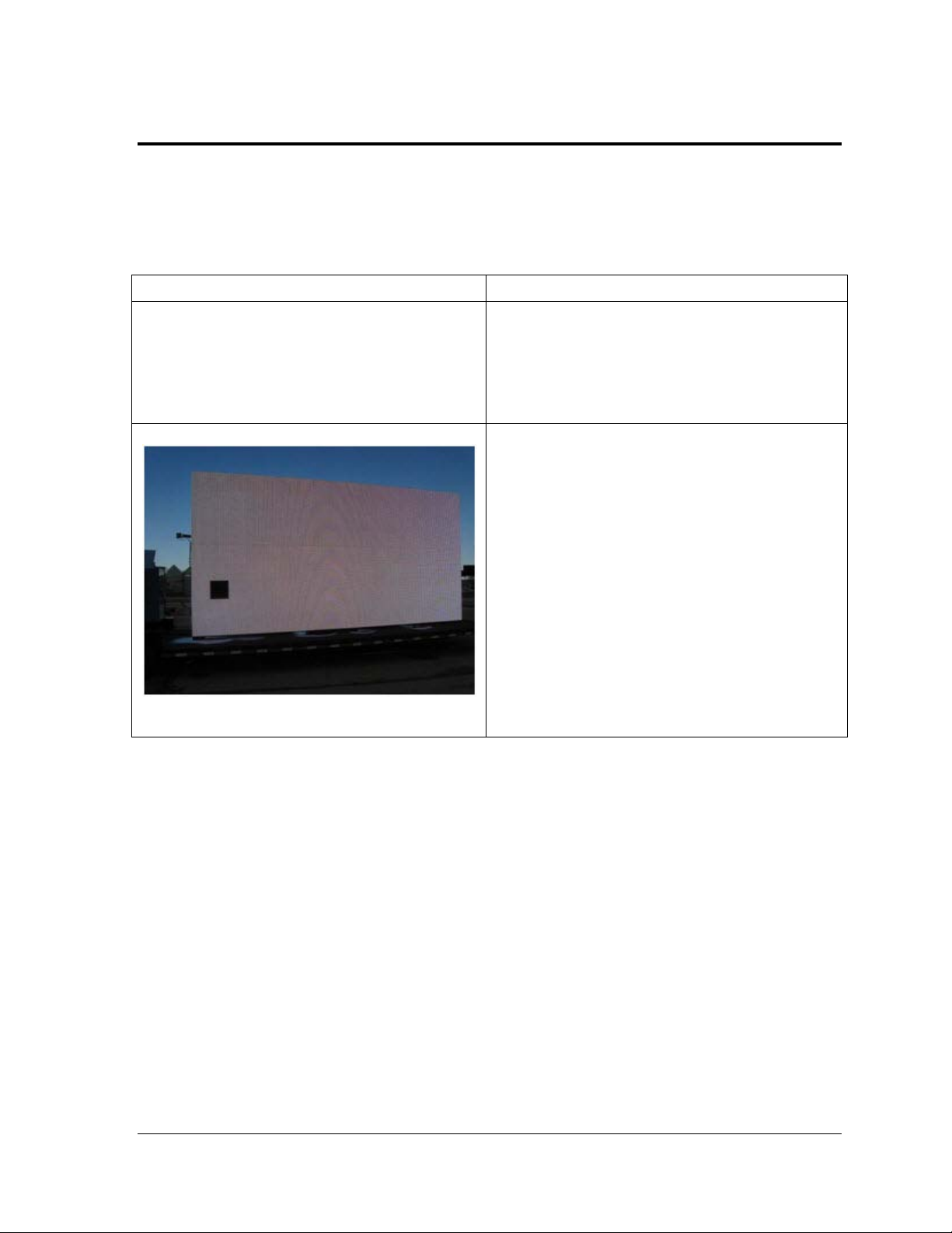
Dis play Vis ual Ins pection
1. Visually inspect the display from ground level for module discoloration or other visual
issues. If you find any issues, contact a NOC technician by calling 1-866-325-8425 and
selecting #2 to recalibrate the display remotely to restore uniformity.
C ompleting the Ins pec tion
1. Contact the NOC technician to ensure diagnostics are clear.
24 Service C all
Page 31

S ection 7: Annual Maintenance Checks
For annual maintenance checks, perform the following service and maintenance procedures.
Required tools: Digital camera, silicone approved for use on aluminum, utility knife, Alcohol or Lens
Cleaning wipes
7.1 Service Instructions
When arriving on site, contact Daktronics Dispatch at 1-866-325-8425 and selecting #1 before
service to announce you are on site. If immediate technical assistance is needed, ask to be
transferred to the technical help desk. If no assistance is needed, proceed with display
service.
S truc tural Ins pec tion
Perform annual visual inspections of the display structure to facilitate repair and lengthen
display life.
• Inspect the structure, ladder, and catwalks for structural integrity.
• Check for possible corrosion, especially at structural tie points and ground rods.
• Check, tighten, and replace fasteners as required.
• Check electronic components for corrosion.
• At least once a year check the inside of the display for signs of water intrusion. Water
can enter the display where weather stripping has deteriorated or where fasteners
have loosened.
Webcam
1. If a lift truck is on site, clean the webcam lens with alcohol or lens cleaning wipes.
Refocus the camera as necessary. Refer to Section 5.3.
Dis play C abinet
1. Check the entire display cabinet for holes from missing nutserts, and other gaps on or
along the edges of back sheets. Check the rear of the display for holes or gouges. Fill any
gaps or holes with silicone. For gaps larger than 6", insert Tek screws into the display to
shorten the gap length. Apply silicone along the seam and over the Tek screw heads.
2. Ensure the doors are locked and on their hinges.
Annual Maintenance Checks 25
Page 32

Wa ter Intrus ion Ins pec tion
1. Check section splices for water trails. Follow the water trail and silicone as needed.
2. Check the inside of the display at several locations for evidence of water intrusion,
corrosion, or water stains. Include the cabinet, modules, power supplies, and PLRs in the
inspection. Photograph any evidence of water intrusion.
Modules
1. Ensure all modules are seated properly. View the display from one end and look down
the face of the display to inspect for modules that are sticking out.
2. Inspect the gaskets on the back of a few modules and ensure they are in good condition.
3. Check modules for pixels out, stuck pixels, bent LEDs, broken louvers, and other issues
that may affect the display image quality.
4. Remove any loose modules and inspect them for stripped gears, broken latches,
unlatched modules, etc. If a module has a broken module latch, replace the module and
send the other module to Daktronics for repair.
R emote E nclos ure
1. Inspect the remote enclosure for overall integrity.
2. Check the remote enclosure for signs of water intrusion, especially at entry locations.
3. If the remote enclosure is equipped with a/c, check the filter. Remove and wash the filter
if it is dirty. Allow the filter to dry before reinserting it.
4. Visually inspect the electronics and cabling in the remote enclosure. Look for worn
cables, connectors, dust in the computer or VIP-4060 fans, corrosion, etc.
5. Check the battery level of the UPS in the remote enclosure.
6. Verify that the key to the spare parts box is in the remote enclosure.
Spare Parts B ox
1. Inspect the spare parts box for signs of water intrusion.
2. Inventory all spare parts in the box.
3. Lock the spare parts box and place the keys in the remote enclosure.
26 Annual Maintenance Checks
Page 33

Dis play Vis ual Ins pection
1. Visually inspect the display from ground level for module discoloration or other visual
issues. If you find any issues, contact a NOC technician by calling 1-866-325-8425 and
selecting #2 to recalibrate the display remotely to restore uniformity.
Display Power
1. Verify the display is properly grounded. Measure the display grounding. It should
measure 10 Ohms or less. If display grounding reads more than 10 Ohms, improve
display grounding until it reads 10 Ohms or less.
2. Verify the voltage on each leg. If the voltage reading is not equal to 120V AC ± 5 V AC on
each leg, check the amperage in the displays breaker panels. Call a NOC technician to
discuss potential actions or solutions.
3. Verify breaker panels, termination panels and cable connections are secure.
C ompleting the Ins pec tion
1. Upon completing the inspection, call 1-877-325-4357 to speak with a Billboard Technician
who will request the findings, enter them into the system, and check for non-visual
diagnostic errors that need resolution.
7.2 Cleaning a Dis play Face
Typically, it is not necessary to clean the display face. If the need arises, use one of the
methods below.
Required tools:
• Five-gallon bucket with cold water.
• Non-abrasive, non-petroleum based detergent.
• 4' – 8' telescoping, soft automotive brush. Daktronics recommends a 10" × 4" brush
head and a brush of light to medium stiffness.
• Soft terry cloth towels.
Wet Cleaning Method
1. Turn off power to the display.
2. Mix mild detergent and cold water in the five-gallon bucket at a ratio of one ounce of
detergent to one gallon of cold water.
3. Clean only a section of modules that are safely within reach of the lift or stage, and then
move to the next section of modules.
Annual Maintenance Checks 27
Page 34

4. Working from top to bottom, use horizontal brush strokes to loosen dirt and grime. Use
light pressure as not to damage LEDs. When finished washing the display face, rinse it
with generous amounts of cold water under low pressure. A spot-free agent, such as Jet
®
Dry
, can be used to reduce water spots.
5. Use a soft, dry terry cloth to dry and remove any excess water. Take care not to damage
LEDs by catching the cloth on them.
6. Allow the display to air-dry for one to two hours before applying power to the display.
7. Dispose of any leftover soapy water in an environmentally safe manner.
Dry Cleaning Method
1. Clean only a section of modules that are safely within reach of the lift or stage, and then
move on to the next section of modules.
2. Working from top to bottom, rub a dry, soft terry cloth towel horizontally across each
row of LEDs. Make four passes per row of LEDs before moving to the next row of LEDs.
3. Take care not to damage LEDs or the plastic louvers by catching them with the cloth.
28 Annual Maintenance Checks
Page 35

S ection 8: R emote Enclosure Parts L ist
1
Door Switch
S-1170
2
Power Protection Kit
0A-1520-3000
3
Dual Thermostat
S-1225
4
Term Block
TB-1069
5
Axial Fan
B-1053
6
500W Axial Fan Heater
A-1819
7
Power Outlet
TB-1128
8
Video Server
A-2138
9
Power Supply
A-2454
10
VIP-4060
0A-1578-0050
11
Computer
0A-1520-1000
12
iBoot
A-2270
13
Air Filter
EN-2242
Breaker
S-1187
The numbers in Figure 35 correspond to the numbers in the table.
Figure 33: Remote Enclosure Components
Part Name Part Number
14 Term Panel:
• Term Block; 3-pos
• Term Block; L-N-G
• Z-filter
• Transformer
•
TB-1069
TB-1130
Z-1007
T-1043
R emote Enclos ure Parts Lis t 29
Page 36

15
Ethernet Switch
A-1815
16
Router
A-2520
30 R emote Enclos ure P arts Lis t
Page 37

S ection 9: S ignal R outing
This section illustrates a general routing of power and signal in the 4000 series digital billboards.
Refer to project-specific drawings for more details.
Signal starts at the PLR. The arrows in the examples below represent the signal path.
Note: Signal routing in odd tall displays have a slightly different signal routing than even tall
displays. Refer to Figure 36 and Figure 37.
Figure 34: Even Tall Signal Routing
Figure 35: Odd Tall Signal Routing
S ignal R outing 31
Page 38

Page 39

S ection 10: Tes ting the Dis play Ground
10.1 Tes ting with a G round Meter
1. Remove any molding covering the ground connection and provide sufficient room for
the jaws of the ground tester to close around the conductor.
2. Open the jaws of the ground tester and make certain that the jaws’ mating surface is
clean and free of dust, dirt, and other foreign matter.
3. Open and close the jaws a few times to allow the jaws to sit on the best mating position.
4. Set the rotary meter to .
5. When powering on the ground tester, the tester will calibrate itself to ensure accuracy.
Wait for the self-calibration to complete. During the process, the LCD will read, “CAL7,
CAL6,…, CAL2, CAL1.” Do not clamp to a conductor or open the jaws during
calibration. The tester will beep when the calibration finishes and is ready for use.
6. Test resistance by clamping the meter on the testing strip provided in the ground meter
kit. The testing strip simulates grounding rings and circuits. Once the reading is attained
from the test strip, remove the meter.
7. Clamp the meter to the electrode or the ground rod-bonding conductor that you are
measuring. Open and close the jaws a few times for better accuracy.
8. The LCD will read the ground resistance measurement. The meter will beep if the
resistance is less than 40 . The measurement should read under 25 . Record the
measurement.
10.2 Tes ting with a Multimeter
1. Remove any molding covering the ground conduction and provide sufficient surface to
contact the probes on the multimeter.
2. Turn the dial on the multimeter to the symbol.
3. Place the red positive probe of the multimeter on the ground wire in the term panel.
4. Place the black ground probe against the main distribution case.
5. The LCD will read the ground resistance measurement. The measurement should read
under 25 . Record the measurement.
T es ting the Display G round 33
Page 40

Page 41

Glossary
Lanyard Attachment Ring: a ring found on the back of each module near the latch release on the
back of the module. The lanyard attaches to the ring and prevents the module from falling.
Latch Release: device that holds the module firmly to the display frame. There are two per module,
one on the top and one on the bottom.
Light Emitting Diode (LED): low energy, high intensity lighting unit.
Line Filter (Z-Filter): device that removes electromagnetic noise that might interfere with local
communication channels from the power system. In the 4000 series digital billboards, line filters are
mounted next to the termination panel.
Louver: a black plastic shade positioned horizontally above each pixel row. Louvers increase the
contrast level on the display face and direct LED light for easier viewing.
Module: consists of a display panel with LEDs, a driver board or logic card, a black plastic housing,
module latch assemblies, and a louver. Each module is individually removable either from the front
or back of the display.
Module Latch: an assembly using a rotating retainer bar to hold the module firmly to the display
frame. There are two per module, one near the top and one near the bottom.
ProLink Router (PLR): the PLR takes data in and then routes that data to other areas in the sign.
There is typically one PLR per display section.
Power Supply: device that receives AC line voltage at its power distribution board, and then supplies
DC voltage to modules and other internal components. One power supply may power several
modules and internal components.
SATA Cable: Serial Advanced Technology Attachment (SATA) allows high-speed signal from
module to module.
Termination Block: an electrical connection point, usually used to connect internal power and signal
wires to wires of the same type coming into the display from an external source.
Glossary 35
Page 42

Page 43

Appendix A: Daktronics Warranty Information
Daktronics Warranty and Limitation of Liability ..................................................... SL-02374
Daktronics Warranty Information 37
 Loading...