

Page 1

OmniSport® 2000 Rodeo
Operation Manual
ED-14843 Rev 3 –22 January 2015
201 Daktronics Drive PO Box 5128 Brookings, SD 57006-5128
Tel: 1-800-DAKTRONICS (1-800-325-8766) Fax: 605-697-4746
www.daktronics.com/support
Page 2

Page 3

ED-14843
Product 1240
Rev 3 – 22 January 2015
DAKTRONICS INC.
Copyright 2007-2015
All rights reserved. While every precaution has been taken in the preparation of this manual, the
publisher assumes no responsibility for errors or omissions. No part of this book covered by the
copyrights hereon may be reproduced or copied in any form or by any means – graphic, electronic, or
mechanical, including photocopying, taping, or information storage and retrieval systems – without
written permission of the publisher.
All Sport® and OmniSport® are registered trademarks of Daktronics, Inc.
Page 4

Page 5

Table of Contents
Section 1: Introduction ................................................................................................................. 1
1.1 Important Safety Instructions ................................................................................................ 1
1.2 Resources .................................................................................................................................. 2
1.3 Reference Guides..................................................................................................................... 2
1.4 Daktronics Exchange and Repair & Return Programs ....................................................... 3
Exchange Program ........................................................................................................... 3
Before Contacting Daktronics ................................................................................. 3
Repair & Return Program ............................................................................................... 4
Shipping Address ..................................................................................................... 4
Daktronics Warranty and Limitation of Liability ........................................................ 4
1.5 Console Revision History ....................................................................................................... 5
Section 2: Timing System Setup ................................................................................................. 7
2.1 Connections on the Console................................................................................................... 7
Power Connection ............................................................................................................ 8
Rodeo Timing Interface Connection .............................................................................. 8
Judges’ Console Connection ........................................................................................... 8
Wireless Photocell Connection ....................................................................................... 9
Daktronics Numeric Display Connection ..................................................................... 9
Serial Connections.......................................................................................................... 10
DakStats Rodeo Software....................................................................................... 10
Matrix Display Connection.................................................................................... 10
Network Connections .................................................................................................... 11
External Switch Inputs .................................................................................................. 11
2.2 Rodeo Timing Interface ........................................................................................................ 12
Power Connection .......................................................................................................... 12
Pushbutton Connection ................................................................................................. 13
Wired Photocell Connection ......................................................................................... 13
Horn Outputs ................................................................................................................. 14
Section 3: General Console Features & Operation ................................................................. 15
3.1 Liquid Crystal Displays (LCDs) .......................................................................................... 15
3.2 The Keypad ............................................................................................................................ 15
Number Key Pad............................................................................................................ 15
Arrow Keys ..................................................................................................................... 15
Enter/Yes ........................................................................................................................ 15
Clear/No ......................................................................................................................... 16
3.3 Built-in Printer ....................................................................................................................... 16
Correct Paper Installation ............................................................................................. 16
3.4 Startup .................................................................................................................................... 16
3.5 Setting Radio Channels on Wireless Consoles .................................................................. 17
Single Controller Systems Channel Setting ................................................................ 17
Multiple Controller with Single Broadcast Group Channel Setting........................ 17
Multiple Controller with Multiple Broadcast Systems Channel Setting ................ 18
Basic Operation of Radio Settings ................................................................................ 18
3.6 Updating Software in the Console ...................................................................................... 19
Table of Contents i
Page 6

Section 4: Rodeo Timer Operations .......................................................................................... 21
4.1 General Rodeo Timer Information ...................................................................................... 21
Manual Timing Mode .................................................................................................... 21
Automatic Timing Mode ............................................................................................... 22
Scored Events.................................................................................................................. 22
Cutting ............................................................................................................................. 23
External Timing .............................................................................................................. 23
4.2 Rodeo Keys............................................................................................................................. 24
Leader Number .............................................................................................................. 24
Leader Time/Score ........................................................................................................ 24
Now Up Number ........................................................................................................... 24
Now Up Time/Score ..................................................................................................... 25
Bubble Time/Score ........................................................................................................ 25
Cattle Number ................................................................................................................ 25
Copy Now Up to Leader ............................................................................................... 26
Clear Now Up ................................................................................................................. 26
Clear Previous ................................................................................................................ 26
Clear Display .................................................................................................................. 26
Reride ............................................................................................................................... 26
No Time — No Score ..................................................................................................... 26
Start .................................................................................................................................. 26
Stop .................................................................................................................................. 26
Reset ................................................................................................................................. 26
Auto Horn ....................................................................................................................... 27
Horn ................................................................................................................................. 27
Set Default Horn Time ................................................................................................... 27
Scoreboard On/Off ........................................................................................................ 27
Paper ................................................................................................................................ 27
External Timing .............................................................................................................. 28
Menu ................................................................................................................................ 28
4.3 Timed Events Keys ................................................................................................................ 28
Auto Timing .................................................................................................................... 28
1 Timer ............................................................................................................................. 28
2 Timers ........................................................................................................................... 28
3 Timers ........................................................................................................................... 28
Set Timer Keys ................................................................................................................ 29
Enable/Disable Photocell .............................................................................................. 29
Penalty ............................................................................................................................. 29
Rearm Stop ...................................................................................................................... 29
4.4 Scored Events & Cutting Keys ............................................................................................. 30
Set Main Clock ................................................................................................................ 30
Count Up/Dn ................................................................................................................. 30
4.5 Judges Keys ............................................................................................................................ 30
Number of Judges .......................................................................................................... 30
Edit Judges Score ............................................................................................................ 31
Accept Judges Score ....................................................................................................... 32
Reset Judges .................................................................................................................... 32
Enable Judges Consoles ................................................................................................. 32
Section 5: Rodeo Menus & Settings .......................................................................................... 33
ii Table of Contents
Page 7

5.1 Menu Navigation .................................................................................................................. 33
5.2 Scoreboard Menu .................................................................................................................. 33
Scoreboard ON/OFF ..................................................................................................... 33
Score Display .................................................................................................................. 34
Dimming ......................................................................................................................... 34
5.3 Print Menu ............................................................................................................................. 35
Logging............................................................................................................................ 35
Intensity ........................................................................................................................... 35
5.4 Setup Timer Menu ................................................................................................................ 35
Timer Precision ............................................................................................................... 35
Timer Mode .................................................................................................................... 35
Beeper .............................................................................................................................. 36
Beep Volume ................................................................................................................... 36
Half Points ...................................................................................................................... 36
Horn ................................................................................................................................. 37
Judge Start ....................................................................................................................... 37
5.5 Setup Photocell Menu ........................................................................................................... 37
Photocell Precision ......................................................................................................... 37
Photocell Arming ........................................................................................................... 37
Photocell Switch ............................................................................................................. 38
5.6 Setup Network Menu ........................................................................................................... 38
Network Enable ............................................................................................................. 38
MAC Address ................................................................................................................. 38
IP Address ....................................................................................................................... 38
Subnet Mask ................................................................................................................... 39
Gateway Address ........................................................................................................... 39
Socket Number ............................................................................................................... 39
5.7 Test Menu ............................................................................................................................... 40
Battery ............................................................................................................................. 40
Scoreboard ...................................................................................................................... 40
Cycle On/Off ........................................................................................................... 40
Section 6: Judges’ Console Operation ..................................................................................... 41
6.1 Console Setup ........................................................................................................................ 41
6.2 Scored Events Operation ...................................................................................................... 41
Maximum Scoring Values ............................................................................................. 42
Re-ride Select .................................................................................................................. 42
Start, Stop, & Reset ........................................................................................................ 42
Score Editing ................................................................................................................... 42
6.3 Cutting Event Operation ...................................................................................................... 43
6.4 Timed Events Operation ...................................................................................................... 43
Appendix A: Reference Drawings ................................................................................................. 45
Appendix B: Quick Reference Guide ............................................................................................ 47
Appendix C: Daktronics Warranty and Limitation of Liability .................................................... 49
Table of Contents iii
Page 8

Page 9

Section 1: Introduction
This manual is designed to explain the operation of OmniSport® 2000 timing console for rodeo events.
For additional information regarding the safety, installation, operation, or service of this system, refer
to the telephone numbers listed in Section 1.4.
1.1 Important Safety Instructions
Read and understand all instructions, both general and for specific sports.
Do not drop the device or immerse it in water.
This device shall not be exposed to dripping or splashing, and no objects filled with
liquid shall be placed upon it.
WARNING! To reduce the risk of fire or electric shock, do not expose this device to rain
or moisture.
An internal battery allows the timer to continue operation for approximately 10 minutes
in the event of a power failure.
CAUTION! DANGER OF EXPLOSION IF BATTERY IS INCORRECTLY REPLACED.
REPLACE ONLY WITH THE SAME OR EQUIVALENT TYPE.
WARNING! Do not expose batteries to excessive heat, such as direct sunlight or
open fire.
Never yank the power cord to pull the plug from the outlet. Grasp the plug and pull to
disconnect.
Do not let the power cord touch hot surfaces or hang over the edge of a table that could
damage or cut the cord.
If an extension cord is necessary, use a three-pronged polarized cord. Arrange the cord
with care so that no one will trip over or pull it out.
Before using an extension cord, inspect the cable thoroughly and verify its compliance
with the local electric codes.
Always turn off and unplug the control equipment when it is not in use.
To avoid electrical shock, do not disassemble the control equipment or electronic controls
of the display. Incorrect reassembly can cause electric shock and faulty operation or
permanent damage to the circuits. Failure to follow this safeguard will make the
warranty null and void.
Inspect console for shipping damage such as rattles and dents, and verify that all
equipment is included as itemized on the packing slip. Immediately report any problems
to Daktronics; save all packing materials if exchange is necessary.
As a safety feature, this device has a three-wire, ground-type plug equipped with a third
(grounding) pin. This plug only fits into a grounding-type power outlet. The outlet shall be
installed near the console and easily accessible. If unable to insert the plug into the outlet,
contact a qualified electrician to replace the obsolete outlet.
Introduction 1
Page 10
Reference Guide
ED/DD #
OmniSport 2000 Rodeo Quick Reference Guide
Provides basic descriptions of rodeo common keys and menu navigation. Included
in Appendix B.
DD2870296
Rodeo Interface Technical Guide
Advanced display interface setup. Available online at www.daktronics.com/manuals.
DD1660229
DakStats Rodeo Manual
Explains the setup and operation of DakStats Rodeo software. Available online at
www.daktronics.com/manuals.
ED-14946
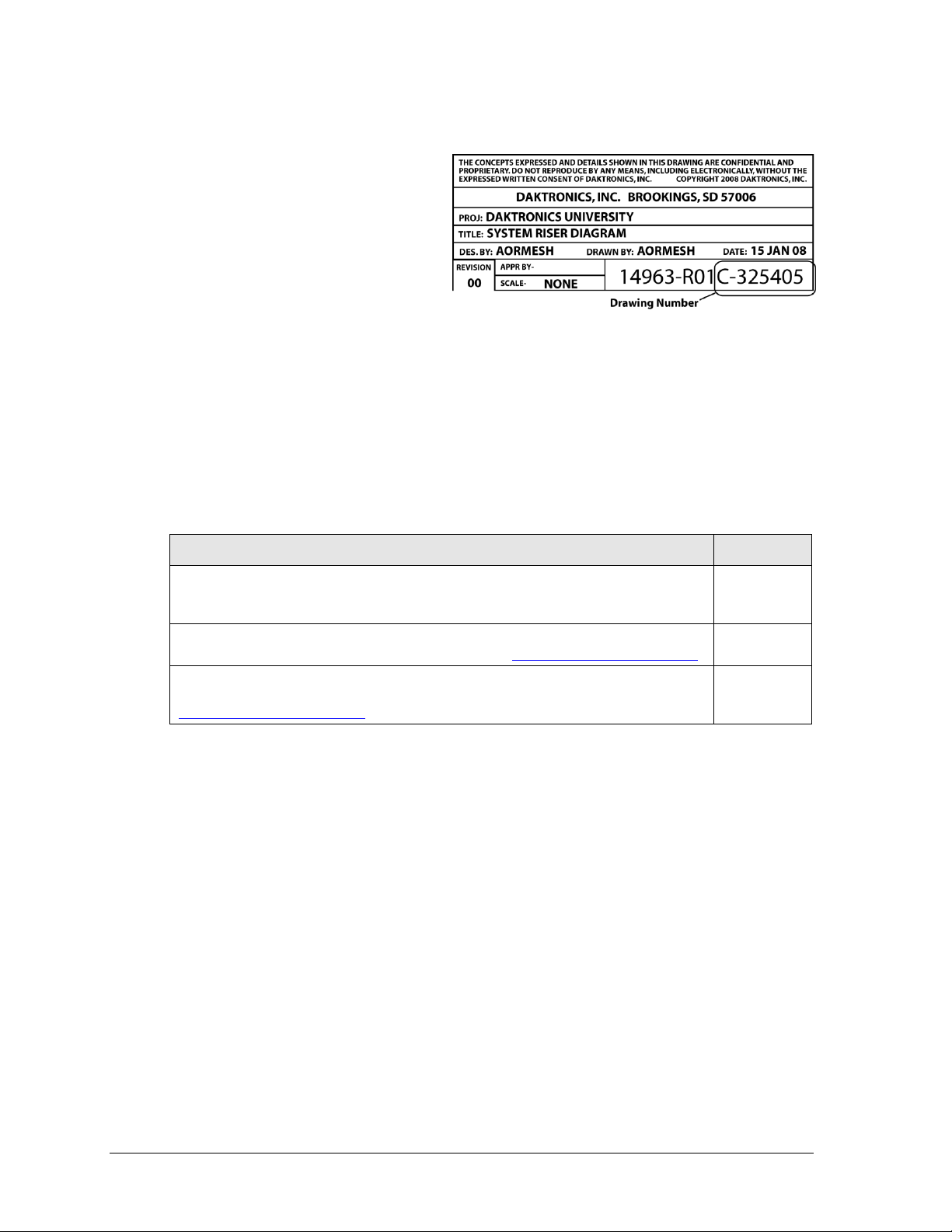
Figure 1: Daktronics Drawing Label
1.2 Resources
Figure 1 illustrates a Daktronics
drawing label. The drawing number is
located in the lower-right corner of a
drawing. This manual refers to
drawings by listing the last set of digits
and the letter preceding them. In the
example, the drawing would be
referred to as Drawing C-325405.
Reference Drawing:
System Riser Diagram ............................................................................Drawing C-325405
Daktronics identifies manuals by an ED or DD number located on the cover page of each
manual. For example, this manual would be referred to as ED-14843.
1.3 Reference Guides
Daktronics provides OmniSport 2000 timing system users with supplemental reference guides.
2 Introduction
Page 11

Market Description
Customer Service Number
Schools (including community/junior colleges), religious
organizations, municipal clubs and community centers
877-605-1115
Universities and professional sporting events, live events
for auditoriums and arenas
866-343-6018
1.4 Daktronics Exchange and Repair & Return Programs
Exchange Program
The Daktronics Exchange Program is a service for quickly replacing key components in need
of repair. If a component fails, Daktronics sends a replacement part to the customer who, in
turn, returns the failed component to Daktronics. This decreases equipment downtime.
Customers who follow the program guidelines explained below will receive this service.
Before Contacting Daktronics
Identify these important numbers:
Assembly Number: _____________________________________________________________
Job/Contract Number: __________________________________________________________
Date Installed: _________________________________________________________________
Daktronics Customer ID Number: ________________________________________________
To participate in the Exchange Program, follow these steps.
1. Call Daktronics Customer Service.
2. If the replacement part fixes the problem, send in the problem part being replaced.
a. Package the old part in the same shipping materials in which the replacement
part arrived.
b. Fill out and attach the enclosed UPS shipping document.
c. Ship the part to Daktronics.
3. The defective or unused parts must be returned to Daktronics within 5 weeks of
initial order shipment.
If any part is not returned within five (5) weeks, a non-refundable invoice will be
presented to the customer for the costs of replenishing the exchange parts inventory
with a new part.
Daktronics reserves the right to refuse parts that have been damaged due to acts of
nature or causes other than normal wear and tear.
Introduction 3
Page 12

Repair & Return Program
For items not subject to exchange, Daktronics offers a Repair & Return Program. To send a
part for repair, follow these steps:
1. Call or fax Daktronics Customer Service:
Refer to the appropriate market number in the chart listed on the previous page.
Fax: 605-697-4444
2. Receive a case number before shipping.
This expedites repair of the part.
3. Package and pad the item carefully to prevent damage during shipment.
Electronic components, such as printed circuit boards, should be placed in an
antistatic bag before boxing. Daktronics does not recommend using packing ‘peanuts’
when shipping.
4. Enclose:
name
address
phone number
the case number
a clear description of symptoms
Shipping Address
Daktronics Customer Service
[Case #]
201 Daktronics Drive, Dock E
Brookings, SD 57006
Daktronics Warranty and Limitation of Liability
The Daktronics Warranty and Limitation of Liability is located in Appendix C. The Warranty
is independent of Extended Service agreements and is the authority in matters of service,
repair, and display operation.
4 Introduction
Page 13

1.5 Console Revision History
Version 4.10.17 Release date: 17 October 2004
Initial software release
Version 5.6.08 Release date: 8 June 2005
In die C3 of 80C390, the SMOD_1 bit for Serial Port 1 seems to be ignored and the baud
rate is always doubled (WDCON.7=1) so the reload values of Timer 1 were adjusted to
work with this as doubled.
Added an H-segment on digit two of the clock in address 1 for a caption control.
Removed the selection in the menu for start of timer using judge number 1.
Version 5.9.26 Release date: 26 September 2005
Added the ability to take a time input from the FarmTek timer for barrel racing to show
on our displays.
Version 5.12.02 Release date: 2 December 2005
Added a Cutting mode that uses 1, 2, 3 or 5 judge’s consoles to score the event.
Added a Bubble Time/Score key function to the console and in RTD.
Added a Cattle number key function to the console and in RTD.
Added a previous Time/Score section in the RTD.
Added a Clear Previous key function to the console.
Added an Enable/Disable Photocell key to the console.
Added the ability to receive a time input from the FarmTek timer in Timed Events and
Cutting Events.
Added the ability to Start, Stop and Reset from all judge consoles in Scored Events.
Added to the printout for a scored event, which judge console started and stopped the
timer.
Added the entry of an extra judge console to be used as a Start, Stop console.
Added a Menu selection to select if any judge's console can Start/Stop the timer.
Added a warning time in cutting and penning that sounds a .5 second horn when the
warning time is reached.
Changed the Reset Judges key to get the judges consoles to exit scoring if no score was
entered.
Version 6.2.16 Release date: 16 February 2006
Fixed a problem when configured for 1 judge, the score always came back with the status
set to reride on.
Fixed a problem that the Cutting horn time is using the scored event horn time.
Fixed a problem of the Warning horn is not sounding when clock is counting down.
Version 6.9.21 Release date: 21 September 2006
Fixed a problem with entering the # of judges in cutting mode, as it would not let all of
the allowed judges be entered.
Fixed a problem when timing with Farmtek in external timing, if the timer was turned off
or disconnected, the OmniSport timer would not allow the user to switch to a different
timing mode.
Introduction 5
Page 14

Version 7.4.16 Release date: 16 April 2007
Added 2 Rider/2 Stock scoring mode for use with 4 judges only.
Fixed a problem in Separate scoring mode that the judge status would not show on the
console LCD until a judge score was entered.
Version 7.7.5 Release date: 5 July 2007
Added ability for single judge to generate a reride for the 2Rider/2Stock mode.
Version 7.12.26 Release date: 26 December 2007
Fixed a problem with Scored Events with the clock in count down and set for horn after
stop. If the time was stopped before it reached zero the time would get set to zero when
the clock hit zero and blew the horn.
Fixed a problem with half-point scoring set on the leader score would not display all
digits. If the score was entered as 89 it would show 8 on the display.
Version 9.2.16 Release date: 16 September 2009
Modified scoreboard output in cutting so the score will shift right if over 100 so x100 digit
is displayed.
Changed the printer output routines (as done in Omni2000 swim) for the new version of
printer.
Version 13.1.25 Release date: 25 January 2013
Added menu items for network settings.
Added RTD output on the Ethernet jack.
6 Introduction
Page 15
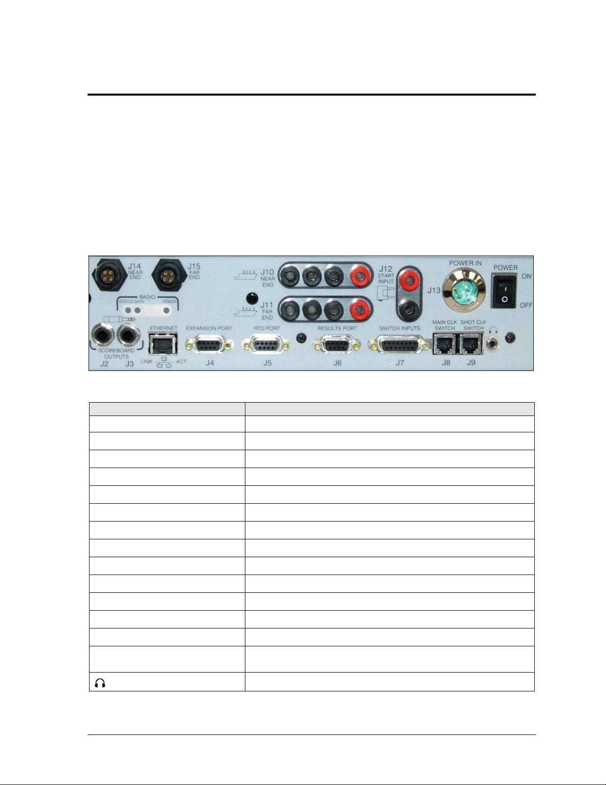
Connection
Function
J2 / J3– SCOREBOARD OUTPUTS
Control numeric rodeo scoreboards/timers
J4 – EXPANSION PORT
Communication with FarmTek wireless photocells
J5 – RTD PORT
Bi-directional communication with Daktronics display control software
J6 – RESULTS PORT
Bi-directional communication with DakStats Rodeo software
J7 – SWITCH INPUTS
Communication with rodeo interface (wired photocells, push buttons)
J8 – MAIN CLK SWITCH
(Not used for rodeo applications)
J9 – SHOT CLK SWITCH
Start/Stop/Reset clock in Scored Events mode
J10 – NEAR END
(Not used for rodeo applications)
J11 – FAR END
(Not used for rodeo applications)
J12 – START INPUT
(Not used for rodeo applications)
J13 – POWER IN
Supplies power from wallpack transformer
J14 – NEAR END
Communication with wireless judges’ consoles
J15 – FAR END
(Not used for rodeo applications)
ETHERNET
Bi-directional communication with DakStats Rodeo software and
Daktronics matrix display control software
Hear the console beeper via headphones
Figure 2: OmniSport 2000 Console Rear View
Section 2: Timing System Setup
2.1 Connections on the Console
Reference Drawing:
Connector Designations: OmniSport 2000 ............................................. Drawing A-154282
It is important to become familiar with the connections on the back of the OmniSport 2000
timing console to ensure all equipment is properly connected before each event. Refer to
Figure 2 and Drawing A-154282. Make ALL connections to the OmniSport 2000 console and
attached equipment BEFORE turning on the console’s power switch.
Timing System Setup 7
Page 16
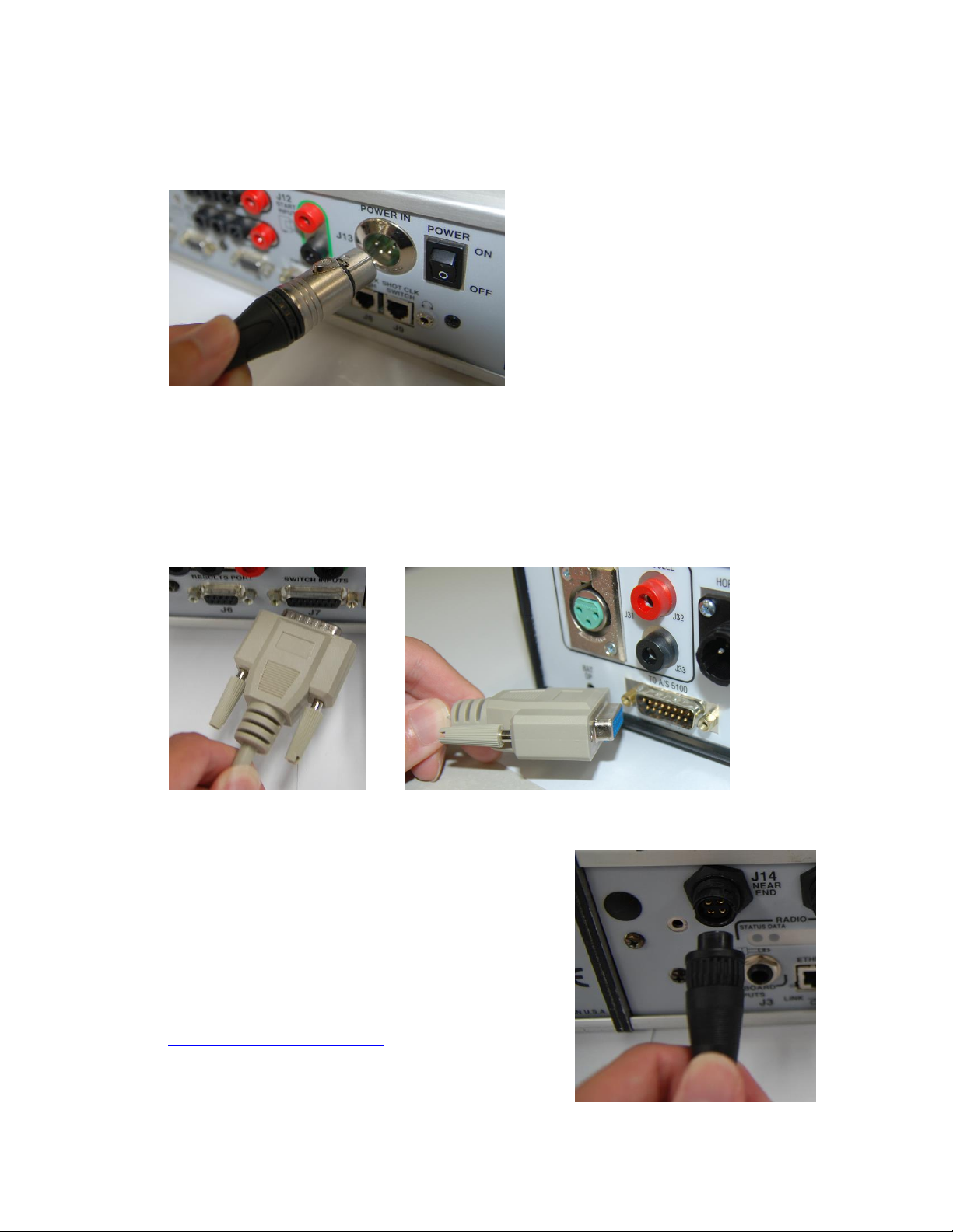
Figure 3: Power Connection
Figure 4: SWITCH INPUTS
Figure 5: TO A/S 5100
Figure 6: Judges’ Console Connection
Power Connection
Connect the power adaptor to the J13 POWER IN jack (Figure 3), and plug the other end into
a 100-240 VAC outlet. Use the rocker switch on the rear of the unit to power it ON and OFF.
Rodeo Timing Interface Connection
The Rodeo Timing Interface is connected to the OmniSport 2000 console via a 15-pin cable
(W-1264). Connect the male end of the cable to the J7 SWITCH INPUTS on the rear of the
OmniSport 2000 (Figure 4), and connect the female end of the cable to the TO A/S 5100 jack on
the rear of the Rodeo Timing Interface (Figure 5). Refer to Section 2.2 for more connections on
the Rodeo Timing Interface.
Judges’ Console Connection
Typically, an RC-100 wireless base station will be
plugged into the J14 NEAR END jack on the rear of the
OmniSport 2000 (Figure 6).
For more information about the RC-100 base station,
refer to the Remote Control System RC-100 All Sport
Operation Manual (ED-15133), available online at
www.daktronics.com/manuals.
8 Timing System Setup
Page 17
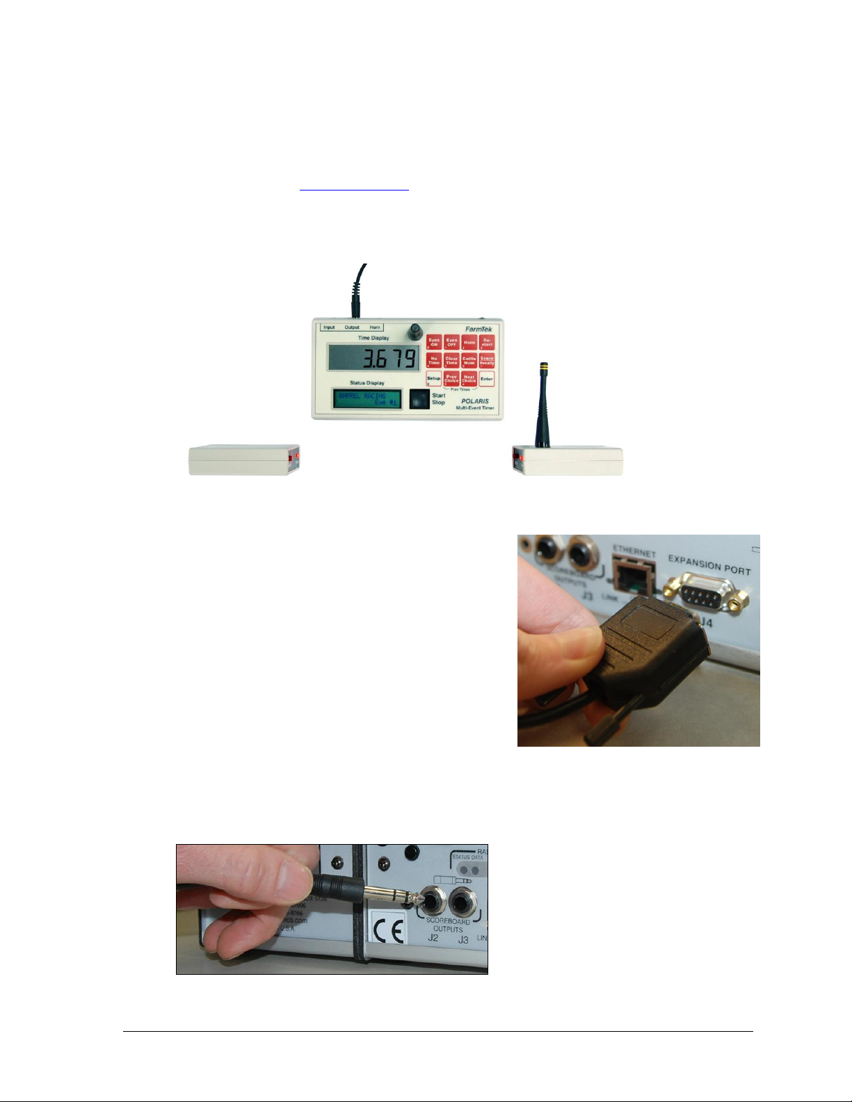
Figure 7: FarmTek Wireless Photocell System
Figure 8: Wireless Photocell Connection
Figure 9: Numeric Scoreboard Plug
Wireless Photocell Connection
Note: If using wired photocells, refer instead to Section 2.2.
The OmniSport 2000 console is capable of interfacing with third-party FarmTek Polaris
wireless photocells (www.farmtek.net). The system consists of a wireless transmitter, wireless
receiver, and the timer (Figure 7). For more information about setting up FarmTek equipment,
consult the manufacturer’s documentation. The timer and photocells are powered by AA and
9V batteries, respectively. Always keep fresh batteries on hand for every event!
To communicate with the wireless photocells,
connect the cable (by FarmTek) between the Output
jack of the Polaris timer and the J4 EXPANSION
PORT on the back of the OmniSport 2000 console
(Figure 8).
Ensure the photocell eyes are aligned and level, with
a clear line of sight between them. Both transmitter
and receiver feature mounting holes for included
tripods. Power on the Polaris timer AFTER powering
on the console or the console will not boot up!
Daktronics Numeric Display Connection
Connect a 1/4" scoreboard signal cable into J2 or J3 SCOREBOARD OUTPUTS as shown in
Figure 9. Make sure that the plug is fully inserted into the jack on the console.
Timing System Setup 9
Page 18
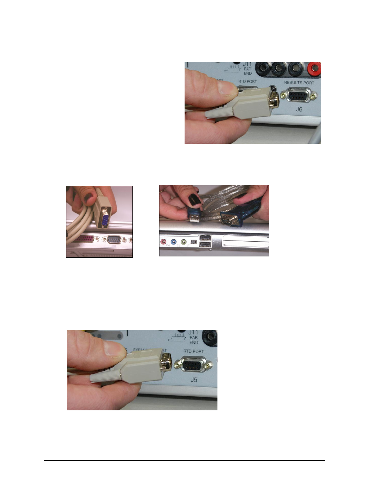
Figure 10: Serial Connection to DakStats Rodeo
Figure 11: Serial Connection
Figure 12: USB-to-Serial Adapter
Figure 13: Serial Connection to Matrix Display
Serial Connections
DakStats Rodeo Software
Using a straight-through 9-pin male to 9pin female serial cable (Daktronics part
# W-1267, 10' or Radio Shack part # 27-
117), connect the male end to J6
RESULTS PORT (Figure 10).
Connect the female end to a serial port
on the computer with the software
(Figure 11). If the computer does not
have a built-in serial port, use a USB-toserial adapter (Daktronics part # A-1801
or Radio Shack part # 26-183) as shown in Figure 12. Drivers for the USB-to-serial adapter
should be found on a CD provided with it or on the manufacturer’s web site.
Matrix Display Connection
Different matrix displays may require different connection methods. A typical connection
method for Daktronics displays uses a 50' (15 m) 9-pin male to 1/4" cable (part # 0A-1240-
0032). Connect the 9-pin male end to J5 RTD PORT (Figure 13). Connect the male 1/4" plug
into a 1/4" phone outdoor J-box (part # 0A-1091-0227).
For more information on outputting data to Daktronics displays, refer to the Rodeo Interface
Technical Guide (DD1660229), available online at www.daktronics.com/manuals.
10 Timing System Setup
Page 19
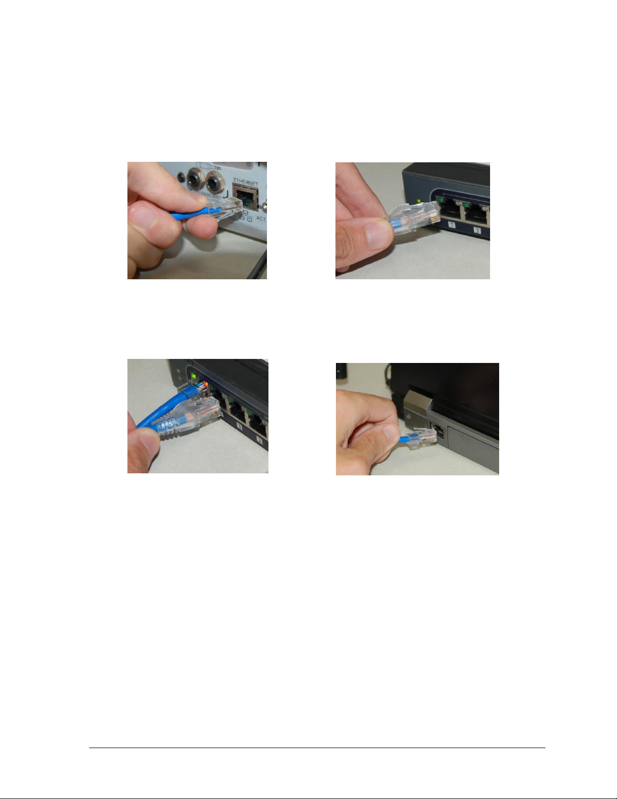
Figure 14: ETHERNET Connection
Figure 15: Network Hub Connection (1)
Figure 16: Network Hub Connection (2)
Figure 17: Computer Connection
Network Connections
The ETHERNET jack allows Real-Time Data (RTD) to be sent over a local area network and
connection to the DakStats Rodeo software.
Connect a Cat5 Ethernet cable between the ETHERNET jack on the OmniSport 2000 console
(Figure 14) and a network hub (Figure 15).
Connect a Cat5 Ethernet cable between the network hub (Figure 16) and the DakStats Rodeo
software and/or Daktronics matrix display control computer (Figure 17). Connect as many
computers as the network hub supports.
Data is sent using UDP protocol as a broadcast packet. The OmniSport 2000 currently
operates using a static IP address. The default address and subnet mask are used with
Daktronics control system networks. If the console is going to operate on a network other
than for a Daktronics control system, an assigned IP address must be obtained and set in the
console. The subnet mask must also be set appropriately for the network. Consult the
facility’s network administrator, and refer to Section 5.6 to change the settings as needed.
Note: Older versions of the console (shipped prior to June 2013) do not have this jack.
If using one of these older consoles, any references in this manual about the Ethernet
jack and network setup may be disregarded. To upgrade, please contact Daktronics.
External Switch Inputs
The OmniSport 2000 console provides external switch inputs for use in Scored Events mode.
Connect a handheld start/stop and reset assembly (0A-1196-0031) to J9 SHOT CLK SWITCH
on the rear of the console. On the handheld switch, toggle the CLOCK START/STOP switch
to start or stop the timer. Press RESET to reset the timer.
Timing System Setup 11
Page 20
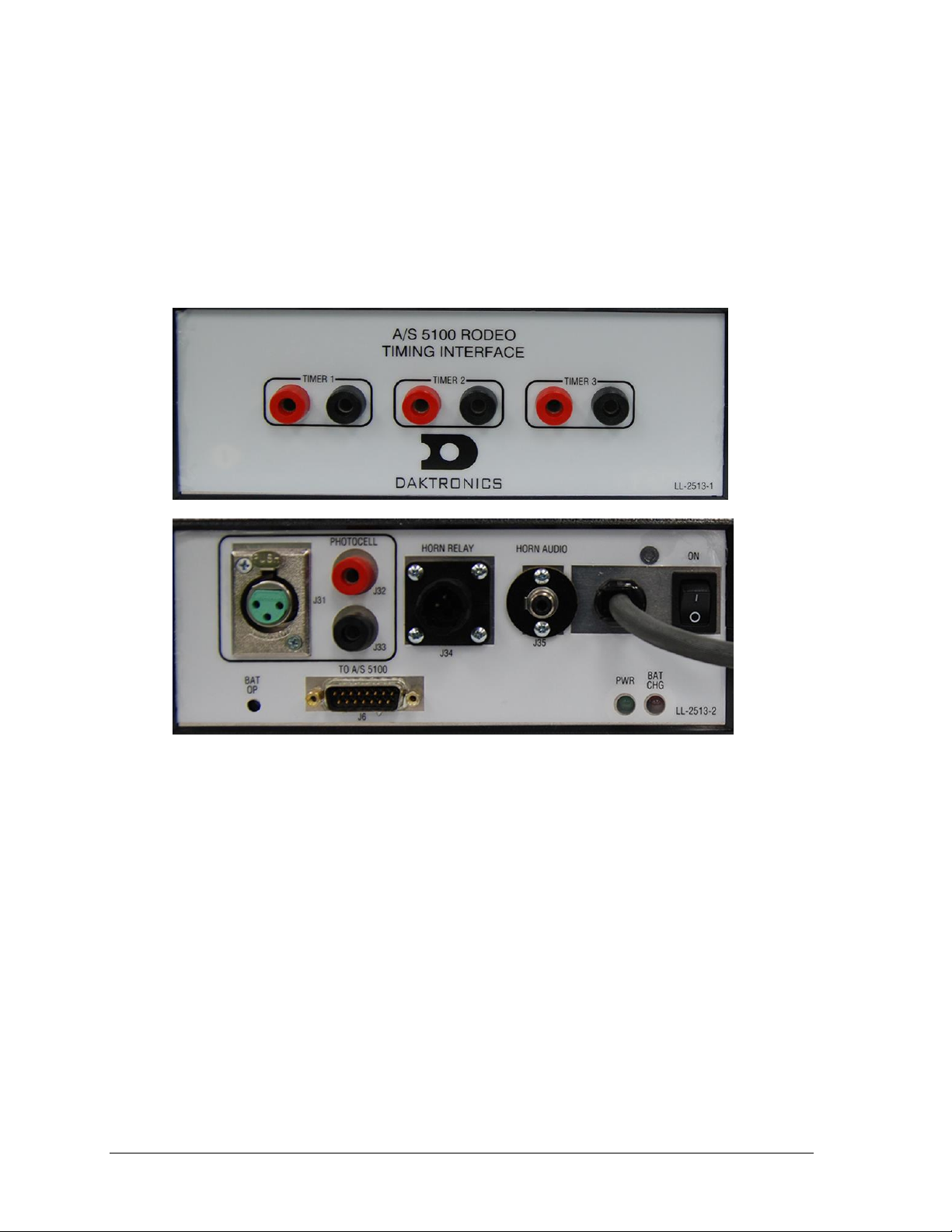
Figure 18: Timing Interface, Front & Rear Views
2.2 Rodeo Timing Interface
Reference Drawing:
Allen Bradley Photocells; 6000 & 9000 Series .......................................... Drawing A-70989
Rodeo Photocell Interface Connector Assignments ............................... Drawing A-147806
External switch inputs, including wired photocells and pushbuttons, are brought into the
OmniSport 2000 console using the AS/5100 Rodeo Timing Interface (0A-1196-0055). Refer to
Figure 18 and Drawing A-147806 for details of each connector on the timing interface.
Power Connection
The Rodeo Timing Interface is equipped with a 3-prong power cord. The interface may
operate while plugged into a standard grounded outlet or via an internal 12 VDC battery.
Use the rocker switch on the rear of the unit to power it ON and OFF.
The unit features two LEDs to indicate power and battery status:
PWR illuminates green when the unit has power.
BAT CHG illuminates red when the unit is plugged in and the battery is charging.
12 Timing System Setup
The unit can operate for ~20 hours on a full charge, but this may vary depending on the age of
the battery. Note that it can take up to 6 hours to fully recharge the battery.
CAUTION! DANGER OF EXPLOSION IF BATTERY IS INCORRECTLY REPLACED.
REPLACE ONLY WITH THE SAME OR EQUIVALENT TYPE.
WARNNING! Do not expose batteries to excessive heat, such as direct sunlight or open fire.
Page 21
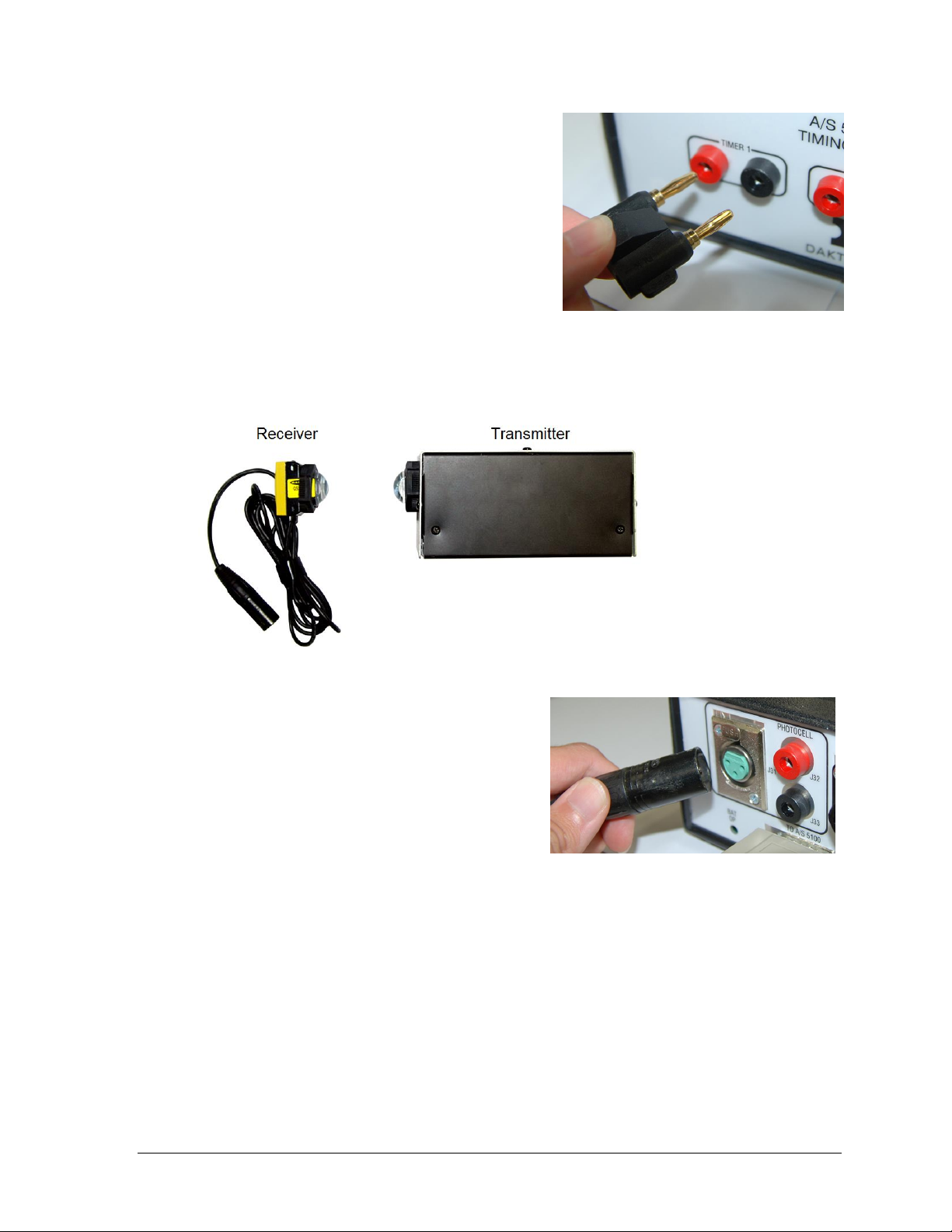
Figure 19: Pushbutton Connection
Figure 20: Wired Photocell System
Figure 21: Photocell Receiver Connection
Pushbutton Connection
Connect up to 3 pushbuttons (part # 0A-1056-0156)
for use in Timed Events to the TIMER 1, TIMER 2,
and TIMER 3 jacks on the front of the Rodeo
Timing Interface. The TIMER 1 input may also be
used to start and stop the clock in Scored Events.
Note: Pay attention to the orientation of the
GND tab of the banana plug – this must
connect into the black jack (Figure 19).
Wired Photocell Connection
Wired photocells may be used for automatic timing of timed events. The system consists of a
transmitter (part # 0A-1163-0025) and a receiver (part # 0A-1163-0024). Refer to Figure 20.
Connect the receiver to the J31 PHOTOCELL
XLR jack on the rear of the Rodeo Timing
Interface (Figure 21).
Note: J32 / J33 is an optional photocell input.
This 2-pin connector does not provide power,
so the photocell receiver would require an
alternate power supply.
The transmitter is housed in an enclosure with two 6 VDC batteries (part # BT-1019). A 12
VDC wall plug-in charger (part # 0A-1088-0013) is included to provide power and charge the
batteries. Use the rocker switch on the rear of the unit to power it on (|) and off (O). The
transmitter is designed to operate 75 hours on a full charge. Note that it can take up to 6
hours to fully recharge the battery.
Ensure the photocell eyes are aligned and level, with a clear line of sight between them.
Both transmitter and receiver feature mounting holes for included tripods (part # A-1509).
CAUTION! DANGER OF EXPLOSION IF BATTERY IS INCORRECTLY REPLACED.
REPLACE ONLY WITH THE SAME OR EQUIVALENT TYPE.
WARNNING! Do not expose batteries to excessive heat, such as direct sunlight or open fire.
Timing System Setup 13
Page 22

Horn Outputs
Connect the 150' (47.5 m) 4-pin horn cable (part # 0A-1163-0007) between the J34 HORN
RELAY jack and the J1 SIGNAL IN jack of the external horn assembly (part # 0A-1163-0005).
The horn is connected to an enclosure with a 12 VDC battery (part # BT-1009). A 12 VDC wall
plug-in charger (part # 0A-1088-0013) may provide power and charge the batteries.
To broadcast a horn tone to a public address (PA) system, connect a male-RCA-to-male-XLR
audio cable (part # 0A-1163-0032) between the J35 HORN AUDIO jack and the PA system
(by others).
14 Timing System Setup
Page 23

Figure 22: OmniSport 2000 Timing Console
Figure 23: OmniSport 2000 Keypad with Rodeo Insert
Section 3: General Console Features & Operation
3.1 Liquid Crystal Displays (LCDs)
The OmniSport 2000 console has
three separate two-line by 16character LCDs to keep the
operator informed (Figure 22).
Section 3.4 describes the readout
on the LCDs when the console is
first powered-up.
3.2 The Keypad
Throughout the manual, keys are referenced with brackets and bold – for example, [ENTER].
The far left side of the keypad on the OmniSport 2000 console has a pocket that allows for a
plastic insert with the names of the keys. The Rodeo insert is Daktronics part # LL-2609. If an
insert is lost or damaged, a printed copy of the insert drawing (located in Appendix A) may
be used until a replacement is ordered.
Note: Remove the protective plastic film from the insert before using it in the console.
The right side of the keypad (Figure 23) has a section of permanent keys. These keys include
the numbers [0]–[9], [CLEAR/NO], [ENTER/YES], and arrows.
Number Key Pad
Press these keys to enter specific numerical information into the timer. The data may pertain
to a specific lane, an event number, or a particular setting among others.
Arrow Keys
These keys are used for menu navigation. The up and down arrows are also labeled NEXT
and LAST; their function will depend on what the LCD is prompting the operator to do.
Enter/Yes
The [ENTER/YES] key has two functions:
Completes an action. As a reminder to press this key, an asterisk appears on the LCD.
Serves as [YES] for input prompts (Y).
General Console Features & Operation 15
Page 24

Figure 24: Console
Printer
Figure 25: Correct Paper Feed
Figure 26: Incorrect Paper Feed
OM N I SP O RT 2000
RODEO TI MI NG
VE R SI ON 13 . 01.25
ED-14865
DAKTRONI CS, I NC
BR O OKI NGS SD
Clear/No
The [CLEAR/NO] key has two functions:
Clears the LCD of numerical information.
Serves as [NO] for input prompts (N).
3.3 Built-in Printer
Daktronics OmniSport 2000 console has a convenient built-in thermal
printer which gives results printouts in under 10 seconds.
Correct Paper Installation
1. Remove the cover from the printer by turning the knob with the
arrow to the left 1/4 turn, or until the arrow points left. Remove the
cover by lifting up and forward on the knob (Figure 24).
2. Remove the old roll of paper.
3. Using a pair of scissors, cut the new roll of paper off to make
the end of the paper square.
4. Place the roll of paper into the printer compartment so that
the paper feeds up from underneath the roll (Figure 25). If the
paper is placed incorrectly (Figure 26), the printer will act like
it is printing, but no text will appear on the paper.
5. Place the newly cut squared edge of the paper into the back
side of the black rubber roller on the printer. The printer
should automatically advance—pulling the paper through
the printer.
6. Place the cover back on and turn the latch to secure.
The thermo printer paper can be ordered from Daktronics—part
# SF-1034. Thermo printer paper is also readily available at
office supply stores (58mm wide and 165' long max).
3.4 Startup
When the OmniSport 2000 timer is initially powered up, the LCDs appear as shown below.
If the timing console includes a radio, read Section 3.5. If the console does not, skip ahead to
Section 3.6 on how to receive software updates from Daktronics. For further explanations on
rodeo timing console operations, refer to Section 3.
16 General Console Features & Operation
Page 25

3.5 Setting Radio Channels on Wireless Consoles
Reference Drawings:
Channel Selection; Multiple Broadcast Group, Gen IV .......................... Drawing A-203113
Installation Details, Gen VI Channel Selection Guide .......................... Drawing A-1109870
The radio receiver units used in Daktronics scoreboards have a channel (CHAN) switch that
can be set from 1–8. The receivers also have a broadcast group (BCAST) setting. The
broadcast group defines a group of radio receivers that “listen” to the channel selected on the
channel switch as well as “listen” for data sent out on their broadcast channel.
Note: The number of available broadcast groups varies depending on the generation of
radio receiver: Gen V radio receivers have 1–4, while Gen VI radio receivers have 1–8.
Each radio receiver will accept data sent from the broadcast channel of its respective
broadcast group, as well as data sent from the “Master Broadcast” channel. This is selected
when the console is set to BCAST 0 and CHAN 00.
In this type of system, the receiver unit at the scoreboard must have the channel switch set to
a specific channel. The operator must know which channel is selected in the scoreboard. The
operator must then enter the specific channel when prompted during console startup.
To determine the settings of a scoreboard, first power it down and shut off any radioequipped consoles in the area. Next, power the scoreboard back up and watch for the radio
settings. The settings will appear as “bX CY” where X is the current broadcast group and Y is
the current channel.
The console automatically detects when a radio transmitter is installed and will prompt the
user for transmitter settings after powering on the console.
Note: If interference from a nearby Daktronics system is suspected, press <CLEAR> at
the “RADIO SETTINGS” prompt to change the channel number.
There are three different radio scenarios that can be accommodated: a single controller
system, a multiple controller system with a single broadcast group, and a multiple controller
system with multiple broadcast groups. These scenarios are described below.
Single Controller Systems Channel Setting
In a single controller system, all radio receivers and all scoreboards receive signal from the
same console at all times. The default channel and broadcast group settings on the receiver
are not typically modified. This is the most common setup.
Typically all single controller systems will use the default setting of BCAST=1, Chan= 1.
All radio receivers in the system must be set to the same values.
Multiple Controller with Single Broadcast Group Channel Setting
In a multiple controller system with a single broadcast group, there may be one console for
each scoreboard and/or one master controller that can run every scoreboard at one time or
take control of a specific scoreboard.
General Console Features & Operation 17
Page 26

Display
Action
The LCD will toggle between
these 2 screens.
The LCD shows the current radio settings along with a prompt
to accept or modify these values.
If the radio settings are correct press [ENTER].
If these values are incorrect press [CLEAR], and the LCD at
bottom left is shown, allowing edit of the channel or broadcast
group setting.
Use the number keypad to enter the desired broadcast group
and press [ENTER] to accept. The asterisk will move to the
channel setting.
Edit the channel number to the desired value and press
[ENTER] to accept.
Broadcast
Group
Channel
Setting
Control Scoreboards
0
0
All Scoreboards
1
0
All in BCAST Group 1
1-8
Set to corresponding BCAST 1
Channel
8*
0
All in BCAST Group 8
1-8
Set to corresponding BCAST 8
Channel
* Gen V radio receivers have only 4 groups; also, on broadcast
groups 2 and 4, only channels 1-4 may be used.
EN T ER TO AC CEPT
CL E AR TO MO DI FY
BC A ST GROUP 1*
RA D I O CHAN 01
RA D I O SETT I NGS
BC A ST X C H AN YY
Multiple controller systems typically use Broadcast 1 and Channel 1 for the first controller
and Channels 2-8 for all remaining controllers. All radio receivers in the system must be set to
Broadcast 1 (BCAST 1).
Multiple Controller with Multiple Broadcast Systems Channel Setting
In a multiple controller system with multiple broadcast groups, there are many consoles that
control multiple scoreboards and/or scoreboard groups. The radio receiver inside the
scoreboard is set to broadcast group 1–4 (Gen V) or 1–8 (Gen VI). By changing the console
settings to the specific broadcast group address, a single console can control all scoreboards
or specific groups of scoreboards.
Typically, all multiple controller systems will use BCAST 1, CHAN 1 for the first controller in
Broadcast Group 1 and BCAST 2, CHAN 1 for the first controller in Broadcast Group 2. All
other consoles in a group are added sequentially.
Basic Operation of Radio Settings
18 General Console Features & Operation
Page 27

Figure 27: DakLoader2 Main Screen
Figure 28: Download Latest Hex Files
3.6 Updating Software in the Console
Equipment needed:
OmniSport 2000 timing console
9-pin male to 9-pin female cable, Daktronics part # W-1267 (in maintenance kit) or Radio
Shack part # 27-117
Computer with an available serial (COM) port; or a USB-to-serial adapter
Computer with Internet connection
To update the OmniSport 2000 timer:
1. Connect the 9-pin serial cable from the COM port of the computer to the J4 EXPANSION
PORT on the console, and then power on the console
2. Open an Internet browser and go to:
http://dakfiles.daktronics.com/download
s/Sports_Products/OmniSport%202000/Ti
mer/DakLoader2.exe
3. A prompt will appear on asking to Run or
Save the program. Click Run (twice if
necessary). The DakLoader2 program
should open (Figure 27).
4. Go to File > Hex Files and click Download
Latest Hex Files (Figure 28).
5. Click Communications and select the
COM port that the 9-pin serial cable is
currently connected to.
6. On the main screen, click Rodeo, and then
click Update.
7. Turn the OmniSport 2000 console OFF and then back ON. After cycling power, the
console should automatically begin programming the hex file selected.
Note: To review DakLoader2 Instructions, go to About > Help using DakLoader2.
To confirm system status or for more information from Daktronics, go to About > About
DakLoader2.
General Console Features & Operation 19
Page 28

Page 29

LE A D# 1262/1 1 .47
CURRENT# 169
: 0.0 0 OK
MA N UAL T I MI N G J1
1 TI MER H=:25
LE A D# 1262/1 1 .47
CURRENT# 169
: 0.0 0 OK
: 0.0 0 : 0 . 00
MA N UAL T I MI N G J1
2 TI MERS H = :25
LE A D# 1262/1 1 .47
CURRENT# 169
: 0.0 0 : 0 . 00
: 0.0 0 : 0 . 00
MA N UAL T I MI N G J1
3 TI MERS H = :25
Section 4: Rodeo Timer Operations
Reference Drawings:
Rodeo Photocell Interface Connector Assignments............................................ Drawing A-147806
Insert, 0L-212281, OmniSport 2000 Rodeo Timer .............................................. Drawing B-212381
System Riser Diagram; OmniSport 2000 Rodeo setup....................................... Drawing B-220003
4.1 General Rodeo Timer Information
The OmniSport 2000 Timer can be used in four separate modes of operation. Three of the four
modes can be used with an external timer using wireless photocells.
Manual Timing Mode
Manual Timing mode is used for events where a competitor’s time determines the place
winner. Timing inputs are one, two or three manual pushbuttons connected to the Daktronics
photocell interface. Examples of timed events using timer buttons are steer wrestling, calf
roping, and team roping. Press [1 TIMER], [2 TIMER], or [3 TIMER] to select Manual
Timing mode with the appropriate number of timer button inputs.
When in Manual Timing mode:
The left LCD shows the leader number and time along with the current (now up) number.
The center LCD shows the official timer (T) along with each timer value (1, 2, or 3). With
1 or 2 TIMER selected, photocell status is also visible. Refer to the table on the following
page for descriptions of possible photocell statuses.
The right LCD shows the default horn time (H), the current number of timers selected,
and the judges’ console status (J1 or J? if not properly connected/communicating). For
more information about judge’s console operation, refer to Section 6.
Manual Timing 1 Button:
Manual Timing 2 Buttons:
Manual Timing 3 Buttons:
Rodeo Timer Operations 21
Page 30

LCD Indicator
Photocell Status
OK
Photocells are aligned (Normally Closed).
Photocells are not aligned (Normally Open).
--
Photocells are not aligned (Normally Closed).
Photocells are aligned (Normally Open).
XX
Photocell beam was broken. XX equals the number of seconds remaining
for the arming time (time until next break will be accepted).
OFF
Photocells are disabled. If photocells will not be uses for timing an event,
disable them by pressing [ENABLE/DISABLE PHOTOCELL].
LE A D# 1262/1 1 .47
CURRENT# 169
: 0.0 0
: 0.0 0 OK
AU T O TI MI N G J1
H= : MAN
LE A D# 1262/ 89.0
CURRENT# 169
SC O RE 85.0
: 0.0 0 { H= : 8
J1 = 22.0 J2=23.0
J3 = 20.0 J4=20.0
Automatic Timing Mode
Automatic Timing mode is used for events where a photocell pair is used to time
competitors. An example of an event using automatic timing is barrel racing.
Press [AUTO TIMING] to select the Automatic Timing mode.
When in Automatic Timing mode:
The left LCD shows the leader number and time along with the current (now up) number.
The center LCD shows the official timer (T), including penalty times, along with the
photocell time and status (C). Refer to the table below for descriptions of possible
photocell statuses.
The right LCD shows the default horn time (H) as “MAN” for manual and the judges’
console status (J1 or J? if not properly connected/communicating). For more information
about judge’s console operation for entering penalties, refer to Section 6.
Scored Events
Scored Events mode is used for events where a competitor’s score determines the place
winner. Examples of scored events are bull riding, saddle bronc, and bareback. Press
[SCORED EVENTS] to select the Scored Events mode.
When in Scored Events mode:
The left LCD shows the leader number and score along with the current (now up) number.
The center LCD shows the current score, the official timer (T), the timer direction ({ or }),
and the default horn time (H).
The right LCD shows the scores from each configured judge console (up to 4 total).
For more information about judge’s console operation, refer to Section 6.
Note: If a judge console is not properly connected/communicating, a “?” will be next to it.
22 Rodeo Timer Operations
Page 31

LE A D# 1262/1 8 5.0
CURRENT# 169
CU T TI NG 18 5 .0
2:30.00} H=2: 3 0
J1 = 60.0 J2=62.0
J3 = 63.0 OK
LE A D# 1262/1 1 .47
CURRENT# 169
: 0.0 0 0 --
EX T ERN T I MI N G J1
1 TI MER H=:25
LE A D# 1262/1 1 .47
CURRENT# 169
: 0.0 0 0
: 0.0 0 0 --
AU T O TI MI N G J1
EX T TI ME
LEAD# 1262/185.0
CURRENT# 169
CU T TI NG 18 5 .0
: 0.00} EXT E RN
J1 = 60.0 J2=62.0
J3 = 63.0 --
Cutting
The Cutting mode is a scored event, but it uses a different score entry and calculation.
Press [CUTTING] to select the Cutting mode.
When in Cutting mode:
The left LCD shows the leader number and score along with the current (now up) number.
The center LCD shows the current score, the official timer (T), the timer direction ({ or }),
and the default horn time (H).
The right LCD shows the scores from each configured judge console and the photocell
status (C). Refer to the table on the previous page for descriptions of possible photocell
statuses. For more information about judge’s console operation, refer to Section 6.
Note: If a judge console is not properly connected/communicating, a “?” will be next to it.
External Timing
External Timing can be selected for Manual Timing, Automatic Timing, and Cutting modes.
The external setting is needed when using wireless photocells (refer to Section 2.1).
The information shown on each LCD changes slightly for all timing modes to indicate
External Timing is selected.
External Manual Timing 1 Button:
External Automatic Timing:
External Cutting:
Note: When set to External Timing, the photocell status (C) will always be “- -” (Normally
Closed) or “OK” (Normally Open), whether the photocells are in alignment or not. This is
because the status is not passed from the external timer to the OmniSport console.
Rodeo Timer Operations 23
Page 32

Display
Action
NNNN = current setting
Press [LEADER NUMBER], enter the current leader number
using the number keypad, and then press [ENTER].
Display
Action
MM:SS.TH = minutes, seconds,
tenths, hundredths
NNN.N = current setting
Timed Events Mode
Press [LEADER TIME/SCORE], enter the current leader time
using the number keypad, and then press [ENTER].
Scored Events Mode
Press [LEADER TIME/SCORE], enter the current leader score
using the number keypad, and then press [ENTER].
Display
Action
NNNN = current setting
Press [NOW UP NUMBER], enter the current competitor
number using the number keypad, and then press [ENTER].
LE A DER N U MBER
NN N N *
LE A DER T I ME
MM:SS.TH *
LE A DER S C ORE
NN N .N *
NO W UP NUM B ER
NN N N *
4.2 Rodeo Keys
The keys described below are functional for scored and timed events, except where noted.
Information entry prompts for these keys is shown on the right LCD.
Leader Number
Leader Time/Score
Now Up Number
24 Rodeo Timer Operations
Page 33

Display
Action
MM:SS.TH = minutes, seconds,
tenths, hundredths
XXXX = now up number
NNN.N = current score
Timed Events Mode
Press [NOW UP TIME/SCORE], enter the current competitor
time using the number keypad, and then press [ENTER].
Note: This key is disabled in Automating Timing mode.
Scored Events Mode
Press [NOW UP TIME/SCORE], enter the current competitor
score using the number keypad, and then press [ENTER].
Note: To edit the current competitor number, press the up
arrow. Enter the current competitor time using the number
keypad, and then press [ENTER] or the down arrow.
Display
Action
MM:SS.TH = minutes, seconds,
tenths
NNN.N = current setting
Timed Events Mode
Press [BUBBLE TIME/SCORE], enter the bubble time using
the number keypad, and then press [ENTER].
Scored Events Mode
Press [BUBBLE TIME/SCORE], enter the bubble score using
the number keypad, and then press [ENTER].
Display
Action
N = current setting
Press [CATTLE NUMBER], enter the current cattle number
using the number keypad, and then press [ENTER]. The
number will display on the seconds X1 clock digit when the
clock is started, for five seconds.
Entering a blank number will disable the cattle number. Press
[CLEAR] followed by [ENTER] to blank the cattle number.
Note: Cattle number is used for team penning and is only
functional in manual timing modes
BU B BLE T I ME
MM:SS.T *
BU B BLE S C ORE
NN N .N *
CA T TLE N U MBER
N*
NO W UP TI M E
MM:SS.TH *
NO W UP XXX X
SC O RE NNN.N *
Now Up Time/Score
Bubble Time/Score
Cattle Number
Rodeo Timer Operations 25
Page 34

Copy Now Up to Leader
Press [COPY NOW UP TO LEADER] to copy the Now Up number and time/score to the
current leader values. This key could be used when the current competitor has become the
new leader.
Clear Now Up
Press [CLEAR NOW UP] to clear the Now Up number and time/score values on the
scoreboard. This can be used at the end of a run.
Clear Previous
Press [CLEAR PREVIOUS] to clear out the previous competitor number and time/score in
the Real-Time Data (RTD) stream.
Clear Display
Press [CLEAR DISPLAY] to clear all scoreboard items. This can be used at the end of an event.
Reride
Press [RERIDE] to toggle the reride caption/indicator on or off. The reride status quickly
displays on the right LCD.
No Time — No Score
Press [NO TIME — NO SCORE] to display “NO TIME” or “NO SCORE” on the scoreboard
and printout, depending on the current console mode of operation.
Start
Press [START] to start the main timer. In Timed Events mode, all timers start simultaneously.
Stop
Press [STOP] to stop the main timer. In Timed Events mode, all timers stop simultaneously.
Reset
Press [RESET] to set the timer values to their original value. If any timers are currently
running, press [ENTER] to confirm the reset.
Note: If the timer is set to count down (Scored Events mode), the timer will be reset to
the default horn time. In all other cases, the timer or timers will be reset to 0.
26 Rodeo Timer Operations
Page 35

Display
Action
Press [AUTO HORN] followed by a number key:
Press [1] to enable auto horn. The horn will sound when
the default horn time is reached.
Press [2] to disable auto horn. The horn will sound only
when [HORN] is pressed.
Note: Auto horn is always disabled in Automatic Timing mode.
Display
Action
MM:SS = minutes, seconds
Press [SET DEFAULT HORN TIME], enter the time to elapse
before the main horn sounds, and then press [ENTER].
Set the Warning Horn Time as desired (for Cutting and Penning)
and then press [ENTER].
The default horn time will be shown on the main LCD screen.
Note: In Automatic Timing mode, the horn time will show
“MAN” for Manual (the horn only sounds by pressing [HORN]).
In Scored Events mode, the timer will automatically stop when the
default horn time is reached.
Scored and Timed Events modes have separate horn times, and
these values are saved when the console is powered down.
SE T DE F AULT HORN
TI ME M M :SS *
AU T O HO RN- ON
SEL- 1=ON 2=O F F
Auto Horn
Horn
Press [HORN] to manually sound the horn.
Set Default Horn Time
Rodeo Timer Operations 27
Scoreboard On/Off
Press [SCOREBOARD ON/OFF] to quickly toggle the scoreboard output on or off.
Paper
Press [PAPER] to advance the printer paper by one line.
Page 36

Display
Action
External timing mode is required for receiving times from a
wireless photocell system.
Press [EXTERNAL TIMING] followed by a number key:
Press [1] to enable external timing.
Press [2] to disable external timing.
Note: External timing is always disabled in Scored Events.
EX T ERN T I ME- OFF
SEL- 1=ON 2=O F F
External Timing
Menu
Press [MENU] to access various timer settings. Refer to Section 5 for more information.
4.3 Timed Events Keys
Press any of the following timer keys to select a Timed Events mode.
Auto Timing
Press [AUTO TIMING] to select the Automatic Timing mode with photocells.
1 Timer
Press [1 TIMER] to select the Manual Timing mode with one start/stop button timer. The
start and stop for the official timer will be taken from the photocells.
2 Timers
Press [2 TIMERS] to select the Manual Timing mode with two start/stop button timers.
3 Timers
Press [3 TIMERS] to select the Manual Timing mode with three start/stop button timers.
28 Rodeo Timer Operations
Page 37

Display
Action
MM:SS = minutes, seconds,
tenths, hundredths
Press [SET TIMER 1/PHOTOCELL], [SET TIMER 2], or [SET
TIMER 3] to modify the final timer values after a run has been
completed. Enter the desired time using the number keypad,
and then press [ENTER].
Notes:
In Automatic Timing mode, press [SET TIMER 1/
PHOTOCELL] at the completion of a run to modify the
photocell time for the run.
Set Timer keys are enabled only at the end of a run.
Results are sent after each timer value is edited.
The time value set using the Set Timer keys does not
include the penalty time. Press [PENALTY] to set or
modify the penalty time for a run.
Display
Action
MM:SS = minutes, seconds
Press [PENALTY] after a run has been completed, enter the
penalty time using the number keypad, and then press
[ENTER]. The penalty time is added to the current official timer.
The PENALTY caption/indicator will also turn on.
Pressing [PENALTY] a second time clears the penalty time for
the current competitor, restores the official timer to its original
value, and turns off the penalty caption/indicator.
Notes:
[PENALTY] is only enabled after the official timer is set
(individual timers are stopped).
Penalty times are cleared after pressing [RESET] or
[CLEAR NOW UP].
SE T TI MER 1
MM:SS.TH *
PE N ALTY TI ME
MM : SS *
PE N ALTY - OFF
Set Timer Keys
Enable/Disable Photocell
Press [ENABLE/DISABLE PHOTOCELL] to activate or deactivate the photocell input.
Penalty
Rodeo Timer Operations 29
Rearm Stop
Press [REARM STOP] to undo the last [STOP] key press. All timer values will be restored to
the value they would have displayed if they hadn’t been stopped. Once [RESET] has been
pressed, the timers cannot be restored.
Note: This key can be used to undo an accidental stop from manual timers and photocells.
Page 38

Display
Action
MM:SS = minutes, seconds,
tenths, hundredths
Press [SET TIMER 1/PHOTOCELL] to modify the main clock
value before a run has been started. Enter the desired time
using the number keypad, and then press [ENTER].
Display
Action
Press [COUNT UP/DN] followed by a number key:
Press [1] to set the main clock to count up.
Press [2] to set the main clock to count down.
Note: The direction of the main clock is shown by the arrow
on the center LCD.
Display
Action
N = current value
Press [# OF JUDGES], enter the number of judges using the
number keypad, and then press [ENTER].
Note: The number of judges may only be set to 1, 2, or 4 for
Scored Events or 1, 2, 3, or 5 for Cutting.
SE T TI ME
TI MER MM:S S .TH *
MA I N C L OCK- DOWN
1= U P 2= DOWN
NU M BER O F JU D GES
N*
4.4 Scored Events & Cutting Keys
Press [SCORED EVENTS] to select Scored Events mode.
Press [CUTTING] to select Cutting mode.
Set Main Clock
Count Up/Dn
4.5 Judges Keys
Number of Judges
30 Rodeo Timer Operations
Page 39

Not applicable to Cutting
After setting the number of judges, the console prompts for the
scoring mode. Select one of the following scoring modes by
pressing the corresponding number key:
[1] Combined
The score is entered as a total of the rider and stock combined.
[2] Separate
The score is entered separately for the rider and the stock.
[3] Total/Stock
The score is entered as a total combined score and then the
score for just the stock is entered.
[4] 2 Rider/2 Stock
The rider score is entered by judges 1 and 2 and the stock
score is entered by judges 3 and 4. Selecting this mode will
automatically set the number of judges to 4.
Not applicable to Cutting
Select whether to allow half-point scoring:
Press [1] to allow half points.
Press [2] to not allow half points.
Press [ENTER] to accept the selection.
Select the Auto Score setting:
Press [1] to let the console automatically accept the
total score after all judges’ scores are entered.
Press [2] to make the operator manually accept the
total score after all judges’ scores are entered.
Press [ENTER] to accept the selection.
Display
Action
NNN.N = current setting
Press [EDIT JUDGES SCORES] to edit each of the judge’s
scores. This function may be used if incorrect scores are
received or if the remote judges’ consoles are not connected.
Enter the desired score for the first judge using the number
keypad, and then press [ENTER]. Repeat for all remaining
judges. Pressing [ENTER] without entering a score will leave
the score as is and advance to the next judge score.
Press [CLEAR] at any time to abort the edit of scores.
SC O RI NG MO D E 1- C OMBI N E D
SC O RI NG MO D E 2- SEPARATE
SC O RI NG MODE3- TOTAL/STOCK
SC O RI NG MO D E 4- 2 RI DE R/2ST O CK
HA L F PO I NT S - YES
1= Y ES 2=NO
AU T O SC ORE- NO
1= Y ES 2=NO
ED I T S C ORE
JU D GE 1: NN N.N*
Edit Judges Score
Rodeo Timer Operations 31
Page 40

Display
Action
Press [ACCEPT JUDGES SCORES] when all judges’ scores
have been received. This will tally and display the total score.
Note: It is not necessary to press this key if the Auto Score
setting is enabled.
If not all scores have been received before pressing this key, a
message will display on the right LCD stating so.
Display
Action
Press [RESET JUDGES] after one or more judges’ scores
have been received, then press [ENTER] to reset all scores, or
press [CLEAR] to cancel.
Note: With Auto Score enabled, this key must be pressed
before all scores are entered or it is not possible to reset
them. Similarly, if [ACCEPT JUDGES SCORES] has
already been pressed, this key will not function.
JU D GE SCORES
AR E NO T EN T ERED
RE S ET JUDGE
SC O RI NG Y/ N ?
Accept Judges Score
Reset Judges
Enable Judges Consoles
Press [ENABLE JUDGES CONSOLES] to re-enable the judges’ consoles. This would be done
if the scores have been accepted and a correction needs to be made from the judge's consoles.
32 Rodeo Timer Operations
Page 41

MENU-M A I N
1- S CBD M E NU
MENU-SCOREBOARD
1- SCBD ON/OFF
[1] SCBD MENU
[11] SCBD ON/OFF
[12] SCORE DISPLAY
[13] DIMMING
[2] PRINT MENU
[21] LOGGING
[22] INTENSITY
[3] SETUP MENU
[31] TIMER
[311] TIMER PREC
[312] TIMER MODE
[313] BEEPER
[314] BEEP VOLUME
[315] HALF POINTS
[316] HORN
[317] JUDGE START
[32] PHOTOCELL
[321] PCELL PREC
[322] PCELL ARMING
[323] PCELL SWITCH
[33] NETWORK
[331] NETWORK ENABLE
[332] MAC ADDRESS
[333] IP ADDRESS
[334] SUBNET MASK
[335] GATEWAY ADDRES
[336] SOCKET NUMBER
[4] TEST MENU
[41] BATTERY
[42] SCOREBOARD
[421] CYCLE ON/OFF
Main Menu screen
From Main Menu – [1] or [ENTER]
From Main Menu – [1]>[1]
SC B D I S - ON
1= O N 2= OFF
Section 5: Rodeo Menus & Settings
5.1 Menu Navigation
Press [MENU] to access the Main Menu screen. There are
two methods of navigating through the OmniSport menus.
The first method allows the operator to step through each of the menu levels. To use this
method, press [MENU] and then use [←], [→], [↑], and [↓] to scroll through the menus.
Press [ENTER] to select the menu item displayed on the LCD.
The second method is to go directly to a menu. Press [MENU] immediately followed by the
one- to three-digit number from the list below, and the LCD will prompt for the desired setting
or action in that menu. For example, 322 will prompt to enter the photocell arming delay.
When finished navigating the menus and adjusting the desired settings, press [MENU] to exit.
Each menu setting is described in detail in the following sections.
5.2 Scoreboard Menu
Rodeo Menus & Settings 33
The Scoreboard Menu is where the operator can turn the
scoreboard output ON or OFF, select score display, and set
the dimming (brightness) level.
Scoreboard ON/OFF
This menu is used to toggle the scoreboard output ON/OFF.
Page 42

MENU-SCOREBOARD
2- S CORE DI SPLAY
MENU-SCOREBOARD
3- D I MM I NG
Dimming Levels:
0 = NONE (full bright)
1 = 90%
2 = 80%
3 = 70%
4 = 60%
5 = 50%
6 = 40%
7 = 30%
8 = 20%
9 = 10% (dimmest)
From Main Menu – [1]>[2]
SC O RE DI SP = ON
1= O N 2= OFF
From Main Menu – [1]>[3]
LEVEL(0-9):
3- D I MM I NG N ONE
Press [1] to set the scoreboard output ON. Press [ENTER] to save.
Press [2] to set the scoreboard output OFF. Press [ENTER] to save. The scoreboard will
be blank until: the start of the next event, [RESET] is pressed to re-display data of the
last event, the scoreboard is turned back ON in the menu, or [SCOREBOARD ON/OFF]
is pressed.
When to use this:
The scoreboard is displaying false information due to equipment or operator error and
needs to be blanked.
The error is corrected and the scoreboard output can be turned back on.
Score Display
This menu selects whether to show scores on the scoreboard.
Press [1] to show scores on the scoreboard. Press [ENTER] to save.
Press [2] to not show scores on the scoreboard. Press [ENTER] to save.
When to use this:
There’s only enough room on the scoreboard to show either time or score at one time, and
time is the preferred information to show.
Dimming
This menu is used to adjust the scoreboard dimming
(brightness) level. The dimming setting only applies to
scoreboards configured to receive multi-drop protocol.
Use the number keypad to select one of the values shown in the
table to the right, or use [←][→] to toggle through the levels. To
save the setting, press [ENTER]. To return to the Dimming Menu
without saving, press [CLEAR].
When to use this:
In low light conditions the scoreboard may be too bright.
34 Rodeo Menus & Settings
In direct sunlight the scoreboard may need to be turned
to full bright.
Page 43

MENU-P R I NT E R
1- L OGGI N G
MENU-P R I NT E R
2- I NTE N SI TY
MENU-M A I N
2- P RI NT ME N U
From Main Menu – [2]>[1]
MENU-P R I NT E R
PR I NTE R LO G : ON
From Main Menu – [2]>[1]
PR I NT I NTENSI T Y
LE V EL 1-5: 5*
MENU-T I MER SET U P
1- T I ME R PR E C
From Main Menu – [3]>[1]>[1]
TI MER PREC I SI O N
1- T ENTHS
TI MER PREC I SI O N
2- H UNDRE D THS
MENU-T I MER SET U P
2- T I ME R MO D E
From Main Menu – [3]>[1]
MENU- SETUP
1- T I ME R
From Main Menu – [3]
From Main Menu – [2]
5.3 Print Menu
The Print Menu includes settings related to the OmniSport
2000’s built-in printer.
Logging
Print logging automatically prints event results in real time.
Press [←], [→], [↑], or [↓] to toggle the logging feature. Press [ENTER] to save.
Intensity
The print intensity level can be adjusted from 1 to 5, with 1
being the lightest and 5 being the darkest.
Press the number key that corresponds to one of the five intensity levels. The printer will
print a test message with the selected intensity level to allow comparison. Adjust the level
as needed.
5.4 Setup Timer Menu
Timer Precision
This menu sets how times appear on the console LCD.
This setting is only for 1, 2, and 3 Timers modes.
Press [1] to show times to tenths of a second (0.0). Press [ENTER] to save.
Press [2] to show times to hundredths of a second (0.00). Press [ENTER] to save.
Timer Mode
This menu sets how official time is obtained using three
timers. This setting is only for 3 Timers mode.
Rodeo Menus & Settings 35
Page 44

From Main Menu – [3]>[1]>[2]
3 TI MER MODE
1- A VERAG E TI MI NG
3 TI MER MODE
2- M EDI AN TI MI N G
MENU-T I MER SET U P
3- BEEPER
From Main Menu – [3]>[1]>[3]
TI ME B E EPER- OFF
1= O N 2= OFF
MENU-T I MER SET U P
4- B EEP V O LUME
From Main Menu – [3]>[1]>[4]
BEEPER
BE E P VO LUME: 0
MENU-T I MER SET U P
5- H ALF P O I NT S
From Main Menu – [3]>[1]>[5]
HA L F PO I NT S - YES
1=YE S 2=NO
Press [1] to select Average Timing. The official timer value will be determined by
averaging the three timer values. Press [ENTER] to save.
Press [2] to select Median Timing. The official timer value will be determined by the
median (middle) of the three timer values. Press [ENTER] to save.
Beeper
This menu sets the time running beeper, which makes the
timer beep every second to indicate the time is running.
Press [1] to set the time running beeper ON. Press [ENTER] to save.
Press [2] to set the time running beeper OFF. Press [ENTER] to save.
Beep Volume
This menu is for setting the internal beeper volume when
keys are pressed.
Use [↑][↓] or the [0]-[7] keys to set the volume level, with 7 being the loudest setting.
Press [ENTER] to save.
Half Points
With half-point scoring enabled, scores will include a
decimal point value. With half-point scoring disabled,
scores will be entered as three-digit whole numbers.
Press [1] to enable half-point scoring. Press [ENTER] to save.
Press [2] to disable half-point scoring. Press [ENTER] to save.
36 Rodeo Menus & Settings
Page 45

MENU-T I MER SET U P
6- H ORN
From Main Menu – [3]>[1]>[6]
HO R N AF TER S T OP
1=YE S 2=NO YES
MENU-T I MER SET U P
7- J UDGE STAR T
From Main Menu – [3]>[1]>[7]
AN Y JU D GE START
1=YE S 2=NO YES
From Main Menu – [3]>[2]>[1]
PC E LL PRECI S I ON
1- H UNDRE D THS
PC E LL PRECI S I ON
2- T HOUSA N DTHS
MENU-P C ELL S E TUP
1- P CELL PREC
MENU-P C ELL S E TUP
2- P CELL ARMI NG
From Main Menu – [3]>[2]>[2]
PH O TOCEL L AR M I NG
TI ME 0 3 *
MENU- SETUP
2- P HOTOC E LL
From Main Menu – [3]>[2]
Use the number keypad to enter the arming delay
time, and then press [ENTER] to save.
Horn
This menu allows the final horn to sound in a scored event
even if the clock was stopped before the horn time.
Press [1] to enable horn after stop. Press [ENTER] to save.
Press [2] to disable horn after stop. Press [ENTER] to save.
Judge Start
This menu allows for selecting any judge console to start
the clock in scored events.
Press [1] to enable any judge start. Press [ENTER] to save.
Press [2] to disable any judge start. Press [ENTER] to save.
5.5 Setup Photocell Menu
Photocell Precision
This menu sets how precise times are when using
photocells. This setting is only Automatic Timing mode.
Press [1] to time to hundredths of a second (0.00). Press [ENTER] to save.
Press [2] to time to thousandths of a second (0.000). Press [ENTER] to save.
Photocell Arming
The arming time is the number of seconds after a beam
break where the photocells will be inactive. Any other
beam breaks during this time will be ignored. The
remaining arming time counts down on the LCD.
Rodeo Menus & Settings 37
Page 46

MENU-SETUP
3- NETWORK
MENU-SETUP
1- NETWORK ENABLE
MENU-NETWORK
2- M AC ADDRESS
MENU-NETWORK
3- I P A D DRESS
MENU-P C ELL S E TUP
3- P CELL SWI T C H
From Main Menu – [3]>[2]>[3]
PH O TOCEL L SW I TCH
1- N ORMAL CLO S ED
PH O TOCEL L SW I TCH
2- N ORMAL OPE N
MENU-NETWORK
NETWORK: ON *
From Main Menu – [3]>[3]>[1]
MENU-NETWORK
NETWORK: OFF*
MA C AD D RESS
09:ec:03:02:7d
From Main Menu – [3]>[3]>[2]
I P ADD R ESS
192*168. 0. 55
From Main Menu – [3]>[3]>[3]
From Main Menu – [3]>[3]
Photocell Switch
Photocells can be configured for Normally Open or
Normally Closed contacts via a switch setting on the
photocell eye. In most cases, the photocells will be set to
Normally Closed.
Press [1] for normally closed photocell contacts. Press [ENTER] to save.
Press [2] for normally open photocell contacts. Press [ENTER] to save.
5.6 Setup Network Menu
This menu is used to configure various network settings for
outputting Real-Time Data (RTD) to displays and connecting
to DakStats Rodeo software.
Network Enable
This menu sets the ETHERNET jack output on or off. If the
jack is not needed, it can be turned OFF (default).
Use [←][→] to toggle between ON/OFF and then press [ENTER] to save.
Note: If this setting is set to OFF, all of the menus below will be disabled.
MAC Address
This menu allows the operator to verify the MAC address
of the console. The MAC Address cannot be edited. Press
any key to exit the menu.
IP Address
This menu allows the operator to set or verify the IP address
of the console. The default setting is shown below.
38 Rodeo Menus & Settings
Page 47

MENU-NETWORK
4- S UBNET MAS K
MENU-NETWORK
5- G ATEWA Y ADDRES
MENU-NETWORK
6- S OCKET NUM B ER
SU B NET M A SK
255*255.255. 0
From Main Menu – [3]>[3]>[4]
GA T EWAY ADDR E SS
192.168. 0. 1
From Main Menu – [3]>[3]>[5]
From Main Menu – [3]>[3]>[6]
SO C KET N U MBER
03002*
SO C KET N U MBER
21000*
In most cases, the standard IP address should be used. Press [ENTER] four times or [CLEAR]
twice to keep the IP address as is.
If a custom IP address is required, such as for connecting to a non-Daktronics network, use
the number keypad to enter a new value for each group of numbers and press [ENTER] after
every group. To return to the default address, press [CLEAR] twice before entering the fourth
group of numbers.
Note: Once the console has been successfully connected to a network, it must be
disconnected from the network in order to change the IP address settings.
Subnet Mask
The subnet mask may only be edited if the IP address is set
to custom. The default setting is shown below.
Use the number keypad to enter a new value for each group of numbers and press [ENTER]
after every group. If no change is needed, press [CLEAR] twice to exit the menu.
Gateway Address
The gateway address may only be edited if the IP address is
set to custom. The default setting is shown below.
Use the number keypad to enter a new value for each group of numbers and press [ENTER]
after every group. If no change is needed, press [CLEAR] twice to exit the menu.
Socket Number
This menu allows the operator to set or verify the socket
number of the console. The setting varies by display type:
Galaxy: DVN/DVX:
In most cases, the default socket number “3002” should be used for Daktronics Galaxy
displays. Press [ENTER] once or [CLEAR] twice to exit the menu.
Daktronics DVN/DVX video displays use “21000”. Use the number keypad to enter a new
value and then press [ENTER]. Other values may be required for non-standard applications.
Rodeo Menus & Settings 39
Page 48

MENU-M A I N
4- T EST M E NU
From Main Menu – [4]>[1]
BA T TERY TEST
LEVEL:CHARGED
From Main Menu – [4]>[2]
SB TES T ME N U
1- C YCLE ON/O F F
DI SPLA Y AL L ON
EN T ER TO EX I T
DI SPLA Y AL L OF F
EN T ER TO EX I T
BA T TERY TEST
LEVEL:LOW
5.7 Test Menu
The OmniSport 2000 timer is equipped with test features that
can be used to test battery level and numeric scoreboards.
Battery
The Battery Test allows for the checking of the battery power level.
If the battery level is LOW, plug the console into a power outlet immediately. Press [ENTER]
to exit to the Test Menu.
Scoreboard
The Scoreboard Test allows for the testing of scoreboard drivers.
Cycle On/Off
Press [1] to cycle scoreboard digits ON and OFF. When this menu is selected, an “all on”
signal is sent at intervals of approximately 3 seconds. Press [ENTER] to exit to the Test Menu.
40 Rodeo Menus & Settings
Page 49

EN T ER JUDGE #
-*
JU D GE 1:
JU D GE 1: ^^ .^*
#1262
JU D GE 1: ^^ .^* R
#1 2 62 ^ ^ .^ S
JU D GE 1: ^^ .^* C
#1 2 62 ^ ^ .^ S
JU D GE 1: 20 .0
#1 2 62 OK
JU D GE 1: 20 .0
ACCEPTED
Section 6: Judges’ Console Operation
The judges’ consoles are used to enter scores during scored events. The OmniSport rodeo timer can be
set to use 1, 2, or 4 for Scored Events or 1, 2, 3, or 5 for Cutting. Refer to the system risers Drawing B-
220003 and Drawing A-230608 for connection details.
For more information about the RC-100 wireless system, refer to the Remote Control System RC-100 All
Sport Operation Manual (ED-15133), available online at www.daktronics.com/manuals.
6.1 Console Setup
When the consoles are first connected to the OmniSport
timer they will prompt the user to enter a judge number.
The LCD on the judge’s console will display this prompt and wait for the user to enter a
number from one up to the maximum number of judges’ consoles the OmniSport is
configured to use. If the number has already been used by another judge or is above the
number of judges the console will beep and wait for a new
number. Once the judge’s console has selected a judge
number, the LCD will display which judge number it is set
for as shown at right.
6.2 Scored Events Operation
The request for scores will show on the judges’ consoles after
the timer has stopped. Enter the score(s), and then press
[ENTER] to confirm. If the score is out of the acceptable
range, the console will beep and wait for a different score.
After a valid score is entered, “OK” will appear by the
competitor number. Once the score is accepted, the console
will indicate this.
The four modes of score entry are shown below. Refer to Section 4.5 for selecting score modes.
Combined Mode
In combined mode, the total score for rider and stock is
entered.
Separate Mode
In separate mode, the rider and stock scores are entered
separately.
Total/Stock Mode
In total/stock mode, the total score is entered first, and then
the stock score is entered.
Judges’ Console Operation 41
Page 50

JU D GE 1: ^^ .^*
#1 2 62 Rider
JU D GE 1: ^^ .^*
#1 2 62 Stock
JU D GE 1:R20. 0
#1 2 62 OK
JU D GE 3:
RE A DY TO ST ART
JU D GE 3:
RE A DY TO ST OP
JU D GE 3: 0 .00
PR E SS RESET
Mode
2 Judges
4 Judges
Combined
50.0
50.0
Separate
Stock
Rider
25.0
25.0
25.0
25.0
Total/Stock
Total
Stock
50.0
25.0 or max of
total score
50.0
25.0 or max of
total score
2 Rider/2 Stock
Rider
Stock
N/A
N/A
25.0
25.0
2 Rider/2 Stock Mode
In the 2 rider/2 stock mode, 4 judges’ consoles are always used. Judges 1 and 2 enter the
riders score, and judges 3 and 4 enter the stock score. The four scores are added for the total.
Maximum Scoring Values
Re-ride Select
The judges’ consoles can be used to select a re-ride when
the score is entered. Press the Re-ride/Penalty key to
alternately toggle the re-ride ON and OFF. An “R” appears
to the left of the score if it is ON.
Start, Stop, & Reset
In scored events, a judge console can be used to remotely start, stop and reset the timer. With
one judge, Judge 2 will do this; with two judges, Judge 3 will do this; and with four judges,
Judge 5 will do this. If ANY JUDGE START is set to YES, then any judge console can start,
stop, and reset the timer (refer to Section 5.4).
At this prompt, press [START] to start the timer.
When running, time is shown to the nearest second.
At this prompt, press [STOP] to stop the timer. The
other judges’ consoles will then be able to enter scores.
At this prompt, press [RESET] to reset the timer.
When stopped, time is shown to hundredth of a second.
Score Editing
After a score is entered, it may be changed by pressing [EDIT]. This clears the current score
so a new score may be entered. If the scores have already been accepted, the OmniSport
operator must press [ENABLE JUDGES CONSOLES] to reactivate the [EDIT] key.
42 Judges’ Console Operation
Page 51

JU D GE 1: ^^ .^*
#1262
JU D GE 1:
#1 2 62 PEN ^^*
JU D GE 2:
NO T AC T I VE
6.3 Cutting Event Operation
The request for scores will show on the judges’ consoles after the timer has stopped.
Enter the score(s), and then press [ENTER] to confirm.
In this mode, the judge scores are added for the total score if
there are three or fewer judges. If there are five judges, the
high and low scores are thrown out and the other three are added.
6.4 Timed Events Operation
The Judge 1 console can be used to remotely enter a penalty
in timed events.
Note: All other judges’ consoles show “NOT ACTIVE”.
Power off any consoles that are not currently in use.
Press [PENALTY] to add a five second penalty. Each press will add another five seconds.
When the penalty is correct, press [ENTER]. If the penalty was not entered correctly, it can be
modified by pressing [EDIT]. Once the timer is reset, the penalty cannot be edited.
If the judges’ console is to be used for entering penalties, ensure the OmniSport operator
doesn’t also add penalties as it may result in too much penalty time added to the clock.
Judges’ Console Operation 43
Page 52

Page 53

Appendix A: Reference Drawings
Drawing Title Drawing Number
Rodeo Photocell Interface Connector Assignments ................................................................. A-147806
Connector Designations: OmniSport 2000 ............................................................................... A-154282
Channel Selection; Multiple Broadcast Group, Gen IV ............................................................. A-203113
Insert, LL-2609, OmniSport Rodeo ........................................................................................... B-212381
System Riser Diagram; OmniSport 2000 ................................................................................. B-220003
System Riser: RC-100 - Rodeo/Diving/Sync Swimming ........................................................... A-230608
Insert; LL-2608, RC-100, Rodeo ............................................................................................... A-231529
Installation Details, Gen VI Channel Selection Guide ............................................................. A-1109870
Reference Drawings 45
Page 54

Page 55

Page 56

CURRENT LOOP OUTPUT -
CURRENT LOOP OUTPUT +
FUNCTION
J2-J3 SCOREBOARD OUTPUTS
SHAFT
CONTACT
RING
TIP
GND
RELAY NORMALLY OPEN
RELAY NORMALLY CLOSED
CURRENT LOOP OUT +
CURRENT LOOP OUT -
J7 - SWITCH INPUTS
8
RELAY COMMON
SWITCH INPUT-GND
12
13
14
15
10
11
9
PIN # FUNCTION
SWITCH INPUT 1 +
SWITCH INPUT 2 +
4
6
7
5
2
3
1
RTD CL RX-N
RTD CL RX-P
NOT USED
J5 - RTD PORT
RTD RS-232 RX
NOT USED
NOT USED
RTD CL TX-P
RTD RS-232 TX
GND
FUNCTION
3
7
9
8
5
6
4
PIN #
1
2
NOT USED
NOT USED
NOT USED9
8
7 NOT USED
J4 - EXPANSION PORT
GND
EXPANSION RS-232 TX
EXPANSION RS-232 RX
6
5
4
3
2
1
PIN #
NOT USED
FUNCTION
NOT USED
FUNCTION
SWITCH INPUT 2 -
SWITCH INPUT 2 +
SWITCH INPUT 1 RELAY OUTPUT RELAY OUTPUT +
SWITCH INPUT 1 +
J8 - MAIN START/STOP/HORN
5
6
PIN #
1
2
3
4
SWITCH INPUT 4 +
SWITCH INPUT 4 -
SWITCH INPUT 5 +
SWITCH INPUT 3 +
SWITCH INPUT 3 -
2
3
4
5
6
SWITCH INPUT 5 -
J9 - SHOT CLOCK START/STOP
PIN #1FUNCTION
+VUNREG
FUNCTION
GND
J14 - NEAR LANE
NEAR CAN-H
NEAR CAN-L
4
2
3
1
PIN #
N/C
FUNCTION
14VAC
N/C
14VAC
J13 - POWER IN
PIN #
4
3
2
1
SHELL EARTH GND
START -, SWIN9-N
J12 - START INPUT
2-BLK
1-RED START +, SWIN9-P
PIN # FUNCTION
LM NEAR
CLK NEAR
J10 - NEAR END
4-RED
3-BLK
2-BLK
1-BLK GND
+VUNREG
PIN # FUNCTION
+VUNREG
CLK FAR
LM FAR
J11 - FAR END
FUNCTION
4-RED
3-BLK
2-BLK
1-BLK
PIN #
GND
PIN #
RESULTS CL RX-N
RESULTS CL RX-P
RESULTS CL TX-P
RESULTS RS-232 TX
RESULTS RS-232 RX
J6 - RESULTS PORT
GND5
NOT USED
6
8
9
7
NOT USED
FUNCTION
NOT USED
1
3
4
2
SWITCH INPUT 3 +
SWITCH INPUT 4 +
SWITCH INPUT 5 +
SWITCH INPUT 6 +
SWITCH INPUT 7 +
SWITCH INPUT 8 +
SWITCH INPUT 9 +
J15 - FAR LANE
PIN #
4
3
1
2
FAR CAN-L
FAR CAN-H
+VUNREG
FUNCTION
GND
0A-1240-0082
1001
09/28/13
AH
OMNI SPORT 2000
CONNECTOR DESIGNATIONS: OMNISPORT 2000
CBRECZI 19 JUN 02
1240 R
08 A
1=4
CBRECZI
154282
02
02 25 JAN 13 SMB
ADDED ETHERNET PORT AND AUDIO JACK. UPDATED
REAR JACKS AND LABELS.
1 04 DEC 02 CJB
CHANGED LABEL ON J6 FROM RTD PORT
TO RESULTS PORT.
AUDIO OUTPUT: 3.5mm
ETHERNET PORT:
NETWORK INTERFACE SUPPORTS
AUTO MDI/MDIX - EITHER
CABLE TYPE MAY BE USED.
DAKTRONICS, INC.
17800
Page 57

Page 58

Page 59

Page 60

Page 61

CAN
RS232
POWER
12 VAC
12 VAC
RS232
CAN
POWER
12 VAC
POWER
RS232
CAN
THE CONCEPTS EXPRESSED AND DETAILS SHOWN ON THIS
DRAWING ARE CONFIDENTIAL AND PROPRIETARY. DO NOT
REPRODUCE BY ANY MEANS WITHOUT THE EXPRESSED
WRITTEN CONSENT OF DAKTRONICS, INC.
COPYRIGHT 2012 DAKTRONICS, INC.
DAKTRONICS, INC.
AV
DRAWN: DATE:
SHEET JOB NO:REV
RADIO LINK
SYSTEM RISER: RC-100- RODEO/DIVING/SYNC SWIMMING
RTAGTOW 30 DEC 04
P1110 R
01 A
NONE
230608
02
DATE:REV BY:
02 27 APR 12 JFL
UPDATED RC-100 HANDHELD PART NUMBER
UPDATED BOARDER AND TITLE BLOCK
Page 62

Page 63

AH
RADIO LINK, GEN VI
INSTALLATION DETAILS, GEN VI CHANNEL SELECTION GUIDE
MMILLER 14 AUG 12
P1110 F
01 A
NONE
JCOSE
1109870
00
BCAST GROUP #1 BCAST GROUP #8
BCAST GROUP #2
CHANNELS 1 - 8
AVAILABLE.
BCAST GROUP #7
CHANNELS 1 - 8
AVAILABLE.
INSTEAD OF CONTROLLING EACH SCOREBOARD IN
BROADCAST GROUP #1 INDIVIDUALLY, YOU CAN
ALSO CONTROL ALL 8 USING CHANNEL = 0 SETTING
ON THE ALLSPORT.
INSTEAD OF CONTROLLING EACH SCOREBOARD IN
BROADCAST GROUP #8 INDIVIDUALLY, YOU CAN
ALSO CONTROL ALL 8 USING CHANNEL = 0 SETTING
ON THE ALLSPORT.
ALL BROADCAST GROUPS AND ALL CHANNELS
ADVANCED SETUP CONFIGURATIONS:
- 1 CONSOLE HAS 64 CHANNELS. USING IT AS A MASTER CONTROL:
*RUNS ALL SCOREBOARDS AT ONCE
*CONSOLE RADIO SETTING: BCAST = 0, CHANNEL = 0
- 1 CONSOLE CAN ALSO CONTROL JUST 8 CHANNELS IN A SELECTED GROUP. GROUP CONTROL:
*RUNS ALL SCOREBOARDS ASSIGNED TO BCAST X AND CHANNELS 1 - 8. X COULD BE BCAST GROUP 1, OR 2, OR... 8
*CONSOLE RADIO SETTING: BCAST = X, CHANNEL = 0. X COULD BE BCAST GROUP 1, OR 2, OR... 8
- 1 CONSOLE CAN ALSO CONTROL JUST 1 CHANNEL IN A SELECTED GROUP. INDIVIDUAL CONTROL:
*RUNS ALL SCOREBOARDS ASSIGNED TO BCAST X AND CHANNEL Y. X COULD BE BCAST GROUP 1, OR 2, OR.. 8. Y COULD BE
CHANNEL 1, OR 2, OR.... 8
*CONSOLE RADIO SETTING: BCAST = X, CHANNEL = Y. X COULD BE BCAST GROUP 1, OR 2, OR.. 8. Y COULD BE
CHANNEL 1, OR 2, OR.... 8
NOTE: TO FIND THE SCOREBOARD RADIO SETTING:
- MAKE SURE THE CONSOLE IS TURNED OFF.
- CYCLE POWER TO THE SCOREBOARD
- WATCH THE DIGITS AS THE SCOREBOARD BOOTS UP. YOU WILL SEE A B X AND C Y APPEAR ON THE DIGITS.
Page 64

Page 65

Appendix B: Quick Reference Guide
Quick Reference Guide 47
Page 66

Page 67

201 Daktronics Drive PO Box 5128, Brookings, SD 57006-5128
Tel: 1-800-DAKTRONICS (1-800-325-8766) Fax: 605-697-4700
Web: www.daktronics.com/support
[1] SCBD MENU
[11] SCBD ON/OFF
[12] SCORE DISPLAY
[13] DIMMING
[2] PRINT MENU
[21] LOGGING
[22] INTENSITY
[3] SETUP MENU
[31] TIMER
[311] TIMER PREC
[312] TIMER MODE
[313] BEEPER
[314] BEEP VOLUME
[315] HALF POINTS
[316] HORN
[317] JUDGE START
[32] PHOTOCELL
[321] PCELL PREC
[322] PCELL ARMING
[323] PCELL SWITCH
[33] NETWORK
[331] NETWORK ENABLE
[332] MAC ADDRESS
[333] IP ADDRESS
[334] SUBNET MASK
[335] GATEWAY ADDRES
[336] SOCKET NUMBER
[4] TEST MENU
[41] BATTERY
[42] SCOREBOARD
[421] CYCLE ON/OFF
OmniSport 2000 Rodeo Menu Navigation
Two methods for navigating through the OmniSport 2000 menus:
The first method allows you to step through each of the menu levels. To use this method, press [MENU] and then use [], [], [], and
[] to scroll through the menus. Press [ENTER] to select the menu displayed on the LCD.
The second method is to go directly to a menu. Press [MENU] followed by the one to three digit number from the list below and the LCD
will prompt you for the desired setting or action in that menu. For example, “322” will prompt you to enter the photocell arming delay.
After you are done navigating through the menus, press [MENU] to return to the main menu.
Rodeo Keys
COPY NOW UP TO LEADER copies Now Up number on the scoreboard to the leader position.
LEADER TIME/SCORE sets the time or score for the leader, depending on the current console mode of operation.
LEADER NUMBER sets the number of the current leader shown on the scoreboard.
BUBBLE TIME/SCORE sets the bubble time or score, depending on the current console mode of operation.
CLEAR NOW UP clears the Now Up competitor on the scoreboard.
NOW UP TIME/SCORE sets the time or score for the Now Up competitor, depending on the current console mode of operation.
NOW UP NUMBER sets the number of the current Now Up competitor shown on the scoreboard.
CATTLE NUMBER is used for team penning.
CLEAR DISPLAY clears all data on the scoreboard.
PENALTY sets the penalty time for the current competitor. A second press of the penalty key turns the penalty off.
RERIDE toggles the reride captions on or off.
# OF JUDGES sets the number of judges used in scored events.
EDIT JUDGES SCORES is used to enter or edit the judge's scores.
ACCEPT JUDGES SCORES totals the judges’ scores and displays the score on the scoreboard.
ENABLE JUDGE CONSOLES is used to re-enable the judges’ consoles after the scores have been accepted.
CLEAR PREVIOUS clears out the previous competitor number and time/score.
DD2870296
Rev 0 27 August 2014
Page 1 of 2
RESET JUDGES clears all judges' scores.
SCORED EVENTS selects the Scored Events mode of operation (bull riding, bareback, etc.).
AUTO TIMING selects the Automatic (photocell) mode of operation (barrel racing).
1 TIMER, 2 TIMERS, 3 TIMERS select the manual timing with one, two or three timers, respectively
(steer wrestling, team roping, etc.).
CUTTING selects the Cutting mode of operation.
NO TIME – NO SCORE displays “no time” or “no score” on the scoreboard and printout.
SET TIMER 1/PHOTOCELL sets the Timer 1 time or Photocell time, depending on the current console mode of operation.
SET TIMER 2, SET TIMER 3 sets the Timer 2 or Timer 3 time (if applicable).
ENABLE/DISABLE PHOTOCELL enables or disables photocell input.
Page 68

201 Daktronics Drive PO Box 5128, Brookings, SD 57006-5128
Tel: 1-800-DAKTRONICS (1-800-325-8766) Fax: 605-697-4700
Web: www.daktronics.com/support
REARM STOP cancels any stop that may have occurred during the run and restores the clock to its free-running state.
This can be used to disregard an accidental button press or photocell beam crossing.
START starts all timers.
STOP stops all timers.
RESET resets all timers to 0 for the next run. The clock is reset to the horn time if set to count down in the Scored Events mode.
AUTO HORN selects whether the horn will sound automatically when the horn time is reached. The horn is automatically set to
manual in Auto Timing mode. The horn can be sounded at any time by pressing the HORN key.
COUNT UP/DN sets the clock to count either up or down. This is used only in the Scored Events and Cutting mode.
SET DEFAULT HORN TIME sets the time until the horn sounds in timed or scored events (if Auto Horn is selected).
SCOREBOARD ON/OFF toggles the scoreboard output on or off.
PAPER advances printer the paper.
EXTERNAL TIMING brings in the time from an external FarmTek timer (used for wireless photocells).
MENU displays options available within the sport code.
DD2870296
Rev 0 27 August 2014
Page 2 of 2
Page 69

Appendix C: Daktronics Warranty and Limitation
of Liability
Daktronics Warranty and Limitation of Liability 49
Page 70

Page 71

DAKTRONICS WARRANTY & LI MITATION OF LIA BILITY
This Warranty and Limitation of Liability (the “Warranty”) sets forth the warranty provided by Daktronics with respect to the Equipment. By accepting delivery of the
Equipment, Purchaser agrees to be bound by and accept these terms and conditions. Unless otherwise defined herein, all terms within the Warranty shall have the
same meaning and definition as provided elsewhere in the Agreement.
DAKTRONICS WILL ONLY BE OBLIGATED TO HONOR THE WARRANTY SET FORTH IN THESE TERMS AND CONDITIONS UPON RECEIPT OF FULL PAYMENT FOR THE
EQUIPMENT.
1. Warranty Coverage
2. Exclusion from Warranty Coverage
A. Daktronics warrants to the original end-user that the Equipment will be free from Defects (as defined below) in materials and
workmanship for a period of one (1) year (the “Warranty Period”). The Warranty Period shall commence on the earlier of: (i) four weeks from the date
that the Equipment leaves Daktronics’ facility; or (ii) Substantial Completion as defined herein. The Warranty Period shall expire on the first anniversary
of the commencement date.
“Substantial Completion” means the operational availability of the Equipment to the Purchaser in accordance with the Equipment’s specifications,
without regard to punch-list items, or other non-substantial items which do not affect the operation of the Equipment.
B. Daktronics’ obligation under this Warranty is limited to, at Daktronics’ option, replacing or repairing, any Equipment or part thereof that is found by
Daktronics not to conform to the Equipment’s specifications. Unless otherwise directed by Daktronics, any defective part or component shall be
returned to Daktronics for repair or replacement. This Warranty does not include on-site labor charges to remove or install these components.
Daktronics may, at its option, provide on-site warranty service. Daktronics shall have a reasonable period of time to make such replacements or repairs
and all labor associated therewith shall be performed during regular working hours. Regular working hours are Monday through Friday between 8:00
a.m. and 5:00 p.m. at the location where labor is performed, excluding any holidays observed by either Purchaser or Daktronics.
C. Daktronics shall pay ground transportation charges for the return of any defective component of the Equipment. All such items shall be shipped by
Purchaser DDP Daktronics; designated facility. If returned Equipment is repaired or replaced under the terms of this warranty, Daktronics will prepay
ground transportation charges back to Purchaser and shall ship such items DDP Purchaser’s designated facility; otherwise, Purchaser shall pay
transportation charges to return the Equipment back to the Purchaser and such Equipment shall be shipped Ex Works Daktronics designated facility. All
returns must be pre-approved by Daktronics before shipment. Daktronics shall not be obligated to pay freight for any unapproved return. Purchaser
shall pay any upgraded or expedited transportation charges.
D. Any replacement parts or Equipment will be new or serviceably used, comparable in function and performance to the original part or Equipment, and
warranted for the remainder of the Warranty Period. Purchasing additional parts or Equipment from the Seller does not extend the Warranty Period.
E. Defects shall be defined as follows. With regard to the Equipment (excepting LEDs), a “Defect” shall refer to a material variance from the design
specifications that prohibit the Equipment from operating for its intended use. With respect to LEDs, “Defects” are defined as LED pixels that cease to
emit light. The limited warranty provided by Daktronics does not impose any duty or liability upon Daktronics for partial LED pixel degradation nor does
the limited warranty provide for the replacement or installation of communication methods including but not limited to, wire, fiber optic cable, conduit,
trenching, or for the purpose of overcoming local site interference radio equipment substitutions.
EXCEPT AS OTHERWISE EXPRESSLY SET FORTH IN THIS WARRANTY, TO THE MAXIMUM EXTENT PERMITTED BY APPLICABLE LAW, DAKTRONICS DISCLAIMS
ANY AND ALL OTHER PROMISES, REPRESENTATIONS AND WARRANTIES APPLICABLE TO THE EQUIPMENT AND REPLACES ALL OTHER WARRANTIES OR
CONDITIONS, EXPRESS OR IMPLIED, INCLUDING, BUT NOT LIMITED TO ANY IMPLIED WARRANTIES OR CONDITIONS OF MERCHANTABILITY, FITNESS FOR A
PARTICULAR PURPOSE, ACCURACTY OR QUALITY OF DATA. NO ORAL OR WRITTEN INFORMATION, OR ADVICE GIVEN BY THE COMPANY, ITS AGENTS OR
EMPLOYEES, SHALL CREATE A WARRANTY OR IN ANY WAY INCREASE THE SCOPE OF THIS LIMITED WARRANTY.
THIS LIMITED WARRANTY IS NOT TRANSFERABLE.
The limited warranty provided by Daktronics does not impose any duty or liability upon Daktronics for:
A. Any damage occurring, at any time, during shipment of Equipment unless otherwise provided for in the Agreement. When returning Equipment to
Daktronics for repair or replacement, Purchaser assumes all risk of loss or damage, and agrees to use any shipping containers that might be provided by
Daktronics and to ship the Equipment in the manner prescribed by Daktronics;
B. Any damage caused by the improper installation, adjustment, repair or service of the Equipment by anyone other than personnel of Daktronics or its
authorized repair agents;
C. Damage caused by the failure to provide a continuously suitable environment, including, but not limited to: (i) neglect or misuse, (ii) a failure or
sudden surge of electrical power, (iii) improper air conditioning, humidity control, or other environmental conditions outside of the Equipment’s
technical specifications such as extreme temperatures, corrosives and metallic pollutants, or (iv) any other cause other than ordinary use;
D. Damage caused by fire, flood, earthquake, water, wind, lightning or other natural disaster, strike, inability to obtain materials or utilities, war,
terrorism, civil disturbance or any other cause beyond Daktronics’ reasonable control;
Copyright © Daktronics, Inc. SL-02374 Rev 12 27Jun14 Page 1 of 2
Page 72

DAKTRONICS WARRANTY & LI MITATION OF LIA BILITY
E. Failure to adjust, repair or replace any item of Equipment if it would be impractical for Daktronics personnel to do so because of connection of the
Equipment by mechanical or electrical means to another device not supplied by Daktronics, or the existence of general environmental conditions at the
site that pose a danger to Daktronics personnel;
3. Limitation of Liability
4. Assignment of Rights
5. Governing Law
6. Availability of Extended Service Agreement
F. Any statements made about the product by any salesperson, dealer, distributor or agent, unless such statements are in a written document signed by
an officer of Daktronics. Such statements as are not included in a signed writing do not constitute warranties, shall not be relied upon by Purchaser and
are not part of the contract of sale;
G. Any damage arising from the use of Daktronics products in any application other than the commercial and industrial applications for which they are
intended, unless, upon request, such use is specifically approved in writing by Daktronics;
H. Any performance of preventive maintenance;
J. Third-party systems and other ancillary equipment including without limitation front-end video control systems, audio systems, video processors and
players, HVAC equipment, batteries and LCD screens;
K. Incorporation of accessories, attachments, software or other devices not furnished by Daktronics; or
L. Paint or refinishing the Equipment or furnishing material for this purpose.
Daktronics shall be under no obligation to furnish continued service under this Warranty if alterations are made to the Equipment without the prior
written approval of Daktronics.
It is specifically agreed that the price of the Equipment is based upon the following limitation of liability. In no event shall Daktronics (including its
subsidiaries, affiliates, officers, directors, employees, or agents) be liable for any special, consequential, incidental or exemplary damages arising out of or
in any way connected with the Equipment or otherwise, including but not limited to damages for lost profits, cost of substitute or replacement
equipment, down time, lost data, injury to property or any damages or sums paid by Purchaser to third parties, even if Daktronics has been advised of
the possibility of such damages. The foregoing limitation of liability shall apply whether any claim is based upon principles of contract, tort or statutory
duty, principles of indemnity or contribution, or otherwise.
In no event shall Daktronics be liable to Purchaser or any other party for loss, damage, or injury of any kind or nature arising out of or in connection with
this Warranty in excess of the purchase price of the Equipment actually delivered to and paid for by the Purchaser. The Purchaser’s remedy in any
dispute under this Warranty shall be ultimately limited to the Purchase Price of the Equipment to the extent the Purchase Price has been paid.
The Warranty contained herein extends only to the original end-user (which may be the Purchaser) of the Equipment and no attempt to extend the
Warranty to any subsequent user-transferee of the Equipment shall be valid or enforceable without the express written consent of Daktronics.
The rights and obligations of the parties under this warranty shall not be governed by the provisions of the United Nations Convention on Contracts for
the International Sales of Goods of 1980. Both parties consent to the application of the laws of the State of South Dakota to govern, interpret, and
enforce all of Purchaser and Daktronics rights, duties, and obligations arising from, or relating in any manner to, the subject matter of this Warranty,
without regard to conflict of law principles.
For Purchaser’s protection, in addition to that afforded by the warranties set forth herein, Purchaser may purchase extended warranty services to cover
the Equipment. The Extended Service Agreement, available from Daktronics, provides for electronic parts repair and/or on-site labor for an extended
period from the date of expiration of this warranty. Alternatively, an Extended Service Agreement may be purchased in conjunction with this warranty
for extended additional services. For further information, contact Daktronics Customer Service at 1-800-DAKTRONics (1-800-325-8766).
Copyright © Daktronics, Inc. SL-02374 Rev 12 27Jun14 Page 2 of 2
 Loading...