

Daikin RZQ42TAVJU, RZQ18TAVJU, RZQ48TAVJU, RZR18TAVJU, RZR24TAVJU Installation Manual
...
INSTALLATION MANUAL
SPLIT SYSTEM Air Conditioners
MODELS
RZQ18TAVJU
RZQ24TAVJU
RZQ30TAVJU
RZQ36TAVJU
RZQ42TAVJU
RZQ48TAVJU
RZR18TAVJU
RZR24TAVJU
RZR30TAVJU
RZR36TAVJU
RZR42TAVJU
RZR48TAVJU
Read these instructions carefully before installation.
Keep this manual in a handy place for future reference.
This manual should be left with the equipment owner.
Lire soigneusement ces instructions avant l’installation.
Conserver ce manuel à portée de main pour référence
ultérieure.
Ce manuel doit être donné au propriétaire de l’équipement.
Lea cuidadosamente estas instrucciones antes de instalar.
Guarde este manual en un lugar a mano para leer en caso
de tener alguna duda.
Este manual debe permanecer con el propietario del
equipo.
English
Français
Español
1
1
2
4
5
67
8
3
1
2
3
4
5
6
5
[1]
[2]
[3]
inch (mm)
4 (100) or more
4 (100) or more
12 (300) or more
4 (100) or more
4 (100) or more
40 (1000) or more
8 (200) or more
4 (100) or more
4 (100) or more
[1]
[2]
[3]
4 (100) or more
6 (150)
or more
20 (500)
or less
40 (1000)
or more
6 (150)
or more
6 (150)
or more
40 (1000)
or more
20 (500)
or less
20 (500)
or less
40 (1000)
or more
40 (1000)
or more
8 (200)
or more
4 (100)
or more
4 (100)
or more
12 (300)
or more
inch (mm)
[1]
[2]
[3]
[4]
20 (500) or more
4 (100)
or more
4 (100)
or more
20 (500)
or less
20 (500)
or less
20 (500) or more
40 (1000) or more
40 (1000) or more
40 (1000) or more
40 (1000) or more
4 (100)
or more
4 (100)
or more
inch (mm)
[1]
[2]
L
L
L
A
A
L
H
H
H
H
20 (500)
or more
10 (250)
or less
12 (300)
or more
20 (500)
or less
20 (500)
or less
4 (100)
or more
4 (100)
or more
4 (100)
or more
4 (100)
or more
12 (300)
or more
40 (1000)
or more
L > H
L > H
[3]
[4]
40 (1000)
or more
40 (1000)
or more
inch (mm)
23
figure 1
figure 3
figure 2
figure 4
2
inch (mm)
1
60 (1500) or more
40 (1000) or more
40 (1000) or more
4
2
3
60 (1500) or more
60 (1500) or more
figure 5 figure 6
figure 7 figure 8
[5]
L
H
20 (500)
or more
4 (100)
or more
L > H
inch (mm)
[7]
L
H
A
40 (1000)
or more
40 (1000)
or more
[6]
L
H
A
4 (100)
or more
4 (100)
or more
60 (1500)
or more
[8]
L
H
A
20 (500)
or less
4 (100) or more
40 (1000)
or more
40 (1000)
or more
40 (1000) or more
60 (1500)
or more
A
4 (100)
or more
L
H
18·24 type 30~48 type
20 (500)
or less
20 (500)
or less
figure 8
[1]
[2]
inch (mm)
40 (1000)
or more
4 (100)
or more
20 (500)
or more
4 (100)
or more
20 (500)
or more
12 (300)
or more
1
13/16
(20)
inch (mm)
1
2
3
4
(only 30~48 type)
1
2
3
4
4
5
6
1
2
6
8
3
4
5
7
1
2
3
4
4
1
2
1
2
3
4
5
1
2
[1]
[2]
40 (1000)
or more
8 (200)
or more
4 (100)
or more
80 (2000)
or more
4 (100)
or more
4 (100)
or more
L
A
figure 11
1
7
2
3
inch (mm)
figure 9 figure 10
6-5/16 (160)
4
4 (103)
13-5/8 (345)
inch (mm)
16-1/2 (441)
1
24-3/8 (620)
4
2
6-5/16 (160)
3-9/16 (90) 5/8 (16)
4
3
(18·24 type)
5/8
(16)
2-11/16 (68)
figure 13
4
12-1/2 (318)
inch (mm)
120 (3000)
H
60 (1500)
or more
24 (600)
or more
or more
1
5-1/2 (140) 24-3/8 (620) 5-1/2 (140)
4 (103)
13-5/8 (345)
16-1/2 (421)
4
2
4
3
(30~48 type)
2-3/4 (71)
figure 12
5/8 (16)
5/8
(16)
2-1/2 (58)
12-1/2 (318)
4
figure 14
5
6
figure 15
figure 18
figure 16
figure 19 figure 20
figure 17
(X1M)
8
7
5
6
10
4
7
11
9
2
1
3
12
11
(X2M)
18·24 type
30~48 type
Keep proper
distance
L1 L2
5
(X1M)
8
7
4
1
3
6
2
10
11
9
11
7
(X2M)
1
2
3
IN/D
OUT/D
F1F2 F1 F2
L1 L2
F
1
IN/D OUT/D
F
2F1F2
F1 F2
4
10
2
7
8
3
6
4
5
5
4
1
2
8
7
8
4
2
6
18·24 type
3
1
Conduit mounting
plate (accessory)
2
4
2
Lock nut
Cover
Conduit
5
1
8
2
4
4
2
7
3
6
5
Lock nut
Cover
Conduit
2
Conduit mounting
plate (accessory)
30~48 type
89
1
11
7
figure 21
2
4
3
6
5
figure 22
figure 23
8
3
7
4
1
2
figure 26
6
5
figure 24figure 25
SPLIT SYSTEM Air Conditioners Installation manual
DANGER
WARNING
CONTENTS
1. SAFETY CONSIDERATIONS ..................................................1
2. INTRODUCTION......................................................................2
2-1. Standard operation limit .................................................... 3
2-2. Standard supplied accessories ......................................... 3
3. BEFORE INSTALLATION ........................................................3
4. SELECTING INSTALLATION SITE .........................................3
5. PRECAUTIONS ON INSTALLATION ......................................5
6. REFRIGERANT PIPING ..........................................................6
6-1. Installation tools.................................................................6
6-2. Selecting piping material ...................................................6
6-3. Protection against contamination when installing pipes....6
6-4. Pipe connection................................................................. 6
6-5. Connecting the refrigerant piping ......................................6
6-6. Thermal insulation of piping ..............................................7
6-7. Air tight test and vacuum drying........................................7
7. ELECTRIC WIRING .................................................................8
7-1. Wiring connection example for whole system ...................8
7-2. How to lay the power supply wiring and
transmission wiring............................................................9
7-3. How to connect the power supply wiring...........................9
7-4. Transmission wiring connection procedure.....................10
8. ADDITIONAL REFRIGERANT CHARGE............................... 10
8-1. Before adding refrigerant.................................................10
8-2. Checking the refrigerant tank ..........................................10
8-3. Adding refrigerant............................................................ 10
9. POST-WORK CHECKS ......................................................... 11
10. TEST OPERATION ................................................................11
10-1. Power On–Check Operation .........................................11
10-2. Temperature control operation checklist .......................12
10-3. Final refrigerant charge adjustment...............................12
11. ENERGY SAVING AND OPTIMUM OPERATION.................12
11-1. Three main operation methods are available:...............13
11-2. Several comfort settings are available ..........................13
11-3. Setting of Heat Pump Lockout and
12. CAUTION FOR REFRIGERANT LEAKS ...............................17
Emergency Heat Mode.................................................. 15
1. SAFETY CONSIDERATIONS
Read these “SAFETY CONSIDERATIONS for Installation” carefully before
installing air conditioning equipment. After completing the installation,
make sure that the unit operates properly during the startup operation.
Instruct the customer on how to operate and maintain the unit. Inform
customers that they should store this Installation Manual for future reference.
Always use a licensed installer or contractor to install this product.
Improper installation can result in water or refrigerant leakage, electrical
shock, fire, or explosion.
Meanings of DANGER, WARNING, CAUTION, and NOTE Symbols:
DANGER
WARNING
CAUTION
.......Indicates an imminently hazardous situation which,
if not avoided, will result in death or serious injury.
.....Indicates a potentially hazardous situation which, if
not avoided, could result in death or serious injury.
......Indicates a potentially hazardous situation which, if
not avoided, may result in minor or moderate injury.
It may also be used to alert against unsafe practices
• Refrigerant gas is heavier than air and replaces oxygen. A massive leak can lead to oxygen depletion, especially in basements,
and an asphyxiation hazard could occur leading to serious injury
or death.
• Do not ground units to water pipes, gas pipes, telephone wires,
or lightning rods as incomplete grounding can cause a severe
shock hazard resulting in severe injury or death.
Additionally, grounding to gas pipes could cause a gas leak and
potential explosion causing in severe injury or death.
• If refrigerant gas leaks during installation, ventilate the area
immediately. Refrigerant gas may produce toxic gas if it comes
into contact with fire. Exposure to this gas could cause severe
injury or death.
• After completing the installation work, check that the refrigerant gas does not leak throughout the system.
• Do not install unit in an area where flammable materials are
present due to risk of explosions that can cause serious injury
or death.
• Safely dispose of all packing and transportation materials in
accordance with federal/state/local laws or ordinances.
Packing materials such as nails and other metal or wood parts,
including plastic packing materials used for transportation may
cause injuries or death by suffocation.
• Only qualified personnel must carry out the installation work.
Installation must be done in accordance with this installation
manual. Improper installation may result in water leakage, electric shock, or fire.
• When installing the unit in a small room, take measures to keep
the refrigerant concentration from exceeding allowable safety
limits. Excessive refrigerant leaks, in the event of an accident in
a closed ambient space, can lead to oxygen deficiency.
• Use only specified accessories and parts for installation work.
Failure to use specified parts may result in water leakage, electric shocks, fire, or the unit falling.
• Install the air conditioner or heat pump on a foundation strong
enough that it can withstand the weight of the unit.
A foundation of insufficient strength may result in the unit falling and causing injuries.
• Take into account strong winds, typhoons, or earthquakes
when installing. Improper installation may result in the unit falling and causing accidents.
• Make sure that a separate power supply circuit is provided for
this unit and that all electrical work is carried out by qualified
personnel according to local, state and national regulations. An
insufficient power supply capacity or improper electrical construction may lead to electric shocks or fire.
• Make sure that all wiring is secured, that specified wires are
used, and that no external forces act on the terminal connections or wires. Improper connections or installation may result
in fire.
• Before touching electrical parts, turn off the unit.
• This equipment can be installed with a Ground-Fault Circuit
Interrupter (GFCI). Although this is a recognized measure for
.
additional protection, with the grounding system in North
America, a dedicated GFCI is not necessary.
NOTE
............Indicates situations that may result in equipment or
property damage accidents only.
English 1

• When installing or relocating the system, keep the refrigerant
CAUTION
NOTE
circuit free from substances other than the specified refrigerant
(R410A) such as air. Any presence of air or other foreign substance in the refrigerant circuit can cause an abnormal pressure rise or rupture, resulting in injury.
• Do not change the setting of the protection devices. If the pressure switch, thermal switch, or other protection device is
shorted and operated forcibly, or parts other than those specified by Daikin are used, fire or explosion may occur.
• Do not touch the switch with wet fingers. Touching a switch
with wet fingers can cause electric shock.
• Do not allow children to play on or around the unit to prevent
injury.
• Do not touch the refrigerant pipes during and immediately after
operation as the refrigerant pipes may be hot or cold, depending on the condition of the refrigerant flowing through the
refrigerant piping, compressor, and other refrigerant cycle
parts. It may result in your hands getting burns or frostbite if
you touch the refrigerant pipes.
To avoid injury, give the pipes time to return to normal temperature or, if you must touch them, be sure to wear proper gloves.
• The heat exchanger fins are sharp enough to cut, and can
cause injury if improperly used. To avoid injury, wear gloves or
cover the fins when working around them.
• Insulate piping to prevent condensation.
• Be careful when transporting the product.
• Do not turn off the power immediately after stopping operation.
Always wait for at least 5 minutes before turning off the power.
Otherwise, water leakage may occur.
• Do not use a charging cylinder. Using a charging cylinder may
cause the refrigerant to deteriorate.
Refrigerant R410A in the system must be kept clean, dry, and tight.
•
(a)
Clean and Dry - Foreign materials (including mineral oils such
as SUNISO oil or moisture) should be prevented from getting
into the system.
(b) Tight - R410A does not contain any chlorine, does not
destroy the ozone layer, and does not reduce the earth’s protection again harmful ultraviolet radiation.
R410A can contribute to the greenhouse effect if it is
released. Therefore take proper measures to check for the
tightness of the refrigerant piping installation.
Read the chapter Refrigerant Piping and follow the procedures.
• Since R410A is a blend, the required additional refrigerant must
be charged in its liquid state. If the refrigerant is charged in a
gaseous state, its composition can change and the system will
not work properly.
• The indoor unit is for R410A. See the catalog for indoor models
that can be connected. Normal operation is not possible when
connected to other units.
• Remote controller transmitting distance can be shorter than
expected in rooms with electronic fluorescent lamps (inverter
or rapid start types). Install the indoor unit far away from fluorescent lamps as much as possible.
Indoor units are for indoor installation only. Outdoor units can be
•
installed either outdoors or indoors. This unit is for outdoor use.
• Do not install the air conditioner or heat pump in the following
locations:
(a) Where a mineral oil mist or oil spray or vapor is produced,
for example, in a kitchen.
Plastic parts may deteriorate and fall off or result in water
leakage.
(b) Where corrosive gas, such as sulfurous acid gas, is pro-
duced.
Corroding copper pipes or soldered parts may result in
refrigerant leakage.
(c) Near machinery emitting electromagnetic waves.
Electromagnetic waves may disturb the operation of the
control system and cause the unit to malfunction.
(d) Where flammable gas may leak, where there is carbon fiber,
or ignitable dust suspension in the air, or where volatile
flammables such as thinner or gasoline are handled. Operating the unit in such conditions can cause a fire.
• Take adequate measures to prevent the outdoor unit from being
used as a shelter by small animals. Small animals making contact with electrical parts can cause malfunctions, smoke, or
fire. Instruct the customer to keep the area around the unit
clean.
• Install the power supply and transmission wires for the indoor
and outdoor units at least 3.5 ft. (1 m) away from televisions or
radios to prevent image interference or noise.
Depending on the radio waves, a distance of 3.5 ft. (1 m) may
not be sufficient to eliminate the noise.
• Dismantling the unit, treatment of the refrigerant, oil and additional parts must be done in accordance with the relevant local,
state, and national regulations.
• Do not use the following tools that are used with conventional
refrigerants: gauge manifold, charge hose, gas leak detector,
reverse flow check valve, refrigerant charge base, vacuum
gauge, or refrigerant recovery equipment.
• If the conventional refrigerant and refrigerator oil are mixed in
R410A, the refrigerant may deterioration.
• This air conditioner or heat pump is an appliance that should
not be accessible to the general public.
• As design pressure is 478 psi (3.3 MPa), the wall thickness of
field-installed pipes should be selected in accordance with the
relevant local, state, and national regulations.
Codes and Regulations
This product is designed and manufactured to comply with
national codes. Installation in accordance with such codes and/or
prevailing local codes/regulations is the responsibility of the
installer. The manufacturer assumes no responsibility for equipment installed in violation of any codes or regulations. Rated performance is achieved after 72 hours of operation.
2. INTRODUCTION
1.
This series uses R410A refrigerant. Be absolutely sure to comply
with “6. REFRIGERANT PIPING”, because even greater caution is
needed to prevent impurities from entering R410A (mineral oils and
water).
2.
The design pressure is 478psi (3.3MPa), which means that piping
may be thicker than conventionally, so please refer to “6. REFRIG-
ERANT PIPING”.
3.
This is a mixed refrigerant, so charge as a liquid when adding refrigerant
(If charged as a gas, the composition of the refrigerant may change,
preventing normal operation.)
4.
The indoor unit must use R410A. See the catalog for indoor unit
models which can be connected. (Normal operation is not possible
when connected to other units.)
5.
The power supply of this series is single-phase, 208/230V, 60Hz.
.
2 English
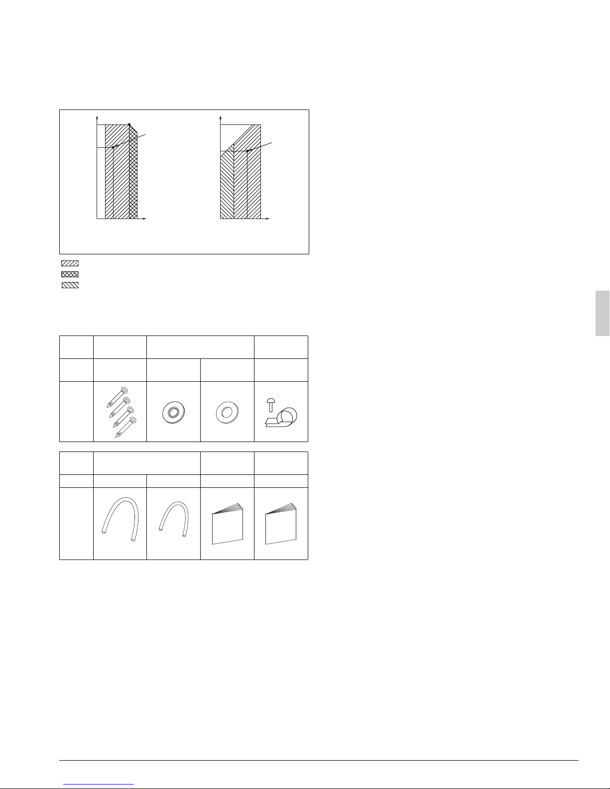
2-1 Standard operation limit
(Small)
Normal operation
The figures below assume following operating conditions for indoor and
outdoor units:
Equivalent pipe length ..................................................25 ft. (7.6 m)
Level difference..................................................................0 ft. (0 m)
Cooling Heating
122(50)
95(35)
Rated
cooling
capacity
60(15.5)
43(6)
41(5)
Rated
heating
capacity
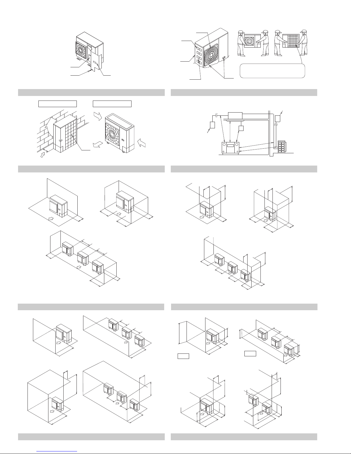
3. BEFORE INSTALLATION
<Transporting the unit>
As shown in figure 2, move the unit slowly. (Take care not to let hands or
other objects come in contact with rear fins.)
(Refer to figure 2)
1. Air outlet grille
2. Intake hole
3. Corner
4. Outdoor unit
5. Handle
6. Front
7. Rear
8. Always hold the unit by the corners, as holding it by the side
intake holes on the casing may cause them to deform.
Use only accessories and parts which are of the designated specification when installing.
23(–5)
50
57.2
Outdoor temperature °FDB (°CDB)
(10)
(14)
Indoor temperature
°FWB (°CWB)
82.4
67
77
(28)
(19)
(25)
–4(–20)
50
Outdoor temperature °FWB (°CWB)
(10)68(20)
Indoor temperature
°FDB (°CDB)
80.6
59
(27)
(15)
Range for operation
Range for pull down operation
Range for warming up operation
2-2 Standard supplied accessories
Make sure that the accessories shown below are all present.
(The accessories can be found behind the front panel.)
Name Clamp Conduit mounting plate
Quantity 4 pcs. 2 pcs. 2 pcs.
Shape
Name Insulation tube
Installation
manual
Quantity 1 pc. 1 pc. 1 1
Shape
(Large)
(Refer to figure 1)
1. Accessories
2. Screw for front panel
3. Front panel
Wire clamp
and screw
1 (only 18·24
Warranty
type)
card
4. SELECTING INSTALLATION SITE
(1) Select an installation site where the following conditions are
satisfied and that meets with your customer’s approval.
• Places which are well-ventilated.
• Places where the unit does not bother next-door neighbors.
• A location where small animals will not make nests in the unit.
• Safe places which can withstand the unit’s weight and vibration and
where the unit can be installed level.
• A locations where there is enough space to install the unit.
• Places where the indoor and outdoor unit’s piping and wiring
lengths come within the allowable ranges.
• A location where there is no risk of flammable gas leaking.
(2) If the unit is installed in a location where it might be exposed to
strong wind, install as per figure 3.
• 11 mph (5 m/s) or higher winds blown against the outdoor unit’s
exhaust cause a deterioration in the system performance. High
winds force re-circulation of the exhaust air into the inlet, which is
known to cause the following effects:
• Reduction in performance.
• Increased frost formation in heating mode.
• System shut down due to increased pressures.
• If very strong wind blows continuously on the air outlet side of the
outdoor unit, the fan may turn in reverse at high speed and break,
so install as per figure 3.
(Refer to figure 3)
1. Turn the air outlet side toward the building’s wall, fence or
windbreak screen.
2. Air inlet grille
3. Ensure there is enough space for installing the unit.
4. Set the outlet side at a right angle to the direction of the
wind.
5. Strong wind
6. Blown air
(3) When installing the unit in a place frequently exposed to snow,
pay special attention to the following:
• Install the outdoor unit on a stand (field supply), so that the bottom
frame is more than 20 in. (500 mm) higher than the expected snow
fall to prevent it from being covered by snow.
• Attach a snow hood (field supply) and a snow vizor (field supply).
• Avoid installation at the place where a snowdrift is generated.
• Further, perform the following countermeasures, since there is risk
that the drain water produced at the defrost operation freezes.
• Install the outdoor unit so that its bottom place level has a sufficient
height from foundation level, so that ice does not grow at the lower
surface of the bottom place of the outdoor unit. (Recommended
clearance: 20 in. (500 mm) or more)
English 3
 Loading...