

Daikin RZQG71LV1B, RZQG100LV1B, RZQG125LV1B, RZQG140LV1B Installation manuals

MODELS
RZQG71LV1B
RZQG100LV1B
RZQG125LV1B
RZQG140LV1B
INSTALLATION MANUAL
Split System air conditioners
READ THESE INSTRUCTIONS CAREFULLY BEFORE INSTALLATION.
KEEP THIS MANUAL IN A HANDY PLACE FOR FUTURE REFERENCE.
(A-1)
D2
D2
(A-2)
1
B2B2
D2
D2D2
EE
L1L1
CC
L2L2
AA
D1D1
HH
B1B1
1
B2B2
D2
D2D2
EE
CC
L1L1
HH
B1B1
1
L2L2
AA
D1D1
2
AB
L1
H1
1324 5
2
1
3
R410A
3
V1-type
~220-240 V
50 Hz
1
6
2
24 5
4 5
3
RZQG71LV1B
RZQG100LV1B
RZQG125LV1B
RZQG140LV1B
C
ONTENTS Page
Split System air conditioners
Safety precautions............................................................................. 1
Before installation.............................................................................. 2
Selecting installation site................................................................... 3
Precautions on installation ................................................................ 4
Installation servicing space ............................................................... 4
Refrigerant pipe size and allowable pipe length................................ 5
Precautions on refrigerant piping ...................................................... 6
Refrigerant piping.............................................................................. 7
Evacuating ........................................................................................ 9
Charging refrigerant .......................................................................... 9
Electrical wiring work ...................................................................... 10
Test operation.................................................................................. 12
Disposal requirements .................................................................... 13
Wiring diagram ................................................................................ 14
READ THESE INSTRUCTIONS CAREFULLY BEFORE
INSTALLATION. KEEP THIS MANUAL IN A HANDY
PLACE FOR FUTURE REFERENCE.
IMPROPER INSTALLATION OR ATTACHMENT OF
EQUIPMENT OR ACCESSORIES COULD RESULT IN
ELECTRIC SHOCK, SHORT-CIRCUIT, LEAKS, FIRE OR
OTHER DAMAGE TO THE EQUIPMENT. BE SURE ONLY
TO USE ACCESSORIES MADE BY DAIKIN WHICH ARE
SPECIFICALLY DESIGNED FOR USE WITH THE
EQUIPMENT AND HAVE THEM INSTALLED BY A
PROFESSIONAL.
IF UNSURE OF INSTALLATION PROCEDURES OR USE,
ALWAYS CONTACT YOUR DAIKIN DEALER FOR
ADVICE AND INFORMATION.
The English text is the original instruction. Other languages are
translations of the original instructions.
AFETY PRECAUTIONS
S
Please read these “SAFETY PRECAUTIONS” carefully before
installing air conditioning equipment and be sure to install it correctly.
After completing installation, conduct a trial operation to check for
faults and explain to the customer how to operate the air conditioner
and take care of it with the aid of the operation manual. Ask the
customer to store the installation manual along with the operation
manual for future reference.
This air conditioner comes under the term “appliances not
accessible to the general public”.
Meaning of WARNING and CAUTION notices.
WARNING
Failure to follow these instructions properly may result in personal injur y
or loss of life.
CAUTION
Failure to observe these instructions properly may result in property
damage or personal injury, which may be serious depending on the
circumstances.
Installation manual
Warning
■ For year round cooling applications with low indoor humidity
conditions, such as Electronic Data Processing rooms, contact
your dealer or see the engineering databook or the service manual.
■ For use of air-conditioning units in applications with temperature
alarm settings it is advised to foresee a delay of 10 minutes for
signalling the alarm in case the alarm temperature is exceeded.
The air-conditioning unit may stop for several minutes during
normal operation for “defrosting of the indoor unit” or when in
“thermostat-stop” operation.
■ Ask your dealer or qualified personnel to carry out installation
work.
Do not attempt to install the air conditioner yourself. Improper
installation may result in water leakage, electric shocks or fire.
■ Install the air conditioner in accordance with the instructions in
this installation manual.
Improper installation may result in water leakage, electric shocks
or fire.
■ Consult your local dealer regarding what to do in case of
refrigerant leakage. When the air conditioner is to be installed in
a small room, it is necessary to take proper measures so that the
amount of any leaked refrigerant does not exceed the
concentration limit in the event of a leakage. Otherwise, this may
lead to an accident due to oxygen depletion.
■ Be sure to use only the specified accessories and parts for
installation work.
Failure to use the specified parts may result in the unit falling,
water leakage, electric shocks or fire.
■ Install the air conditioner on a foundation strong enough to
withstand the weight of the unit.
A foundation of insufficient strength may result in the equipment
falling and causing injury.
■ Carry out the specified installation work after taking into account
strong winds, typhoons or earthquakes.
Failure to do so during installation work may result in the unit
falling and causing accidents.
■ Make sure that a separate power supply circuit is provided for
this unit and that all electrical work is carried out by qualified
personnel according to local laws and regulations and this
installation manual.
An insufficient power supply capacity or improper electrical
construction may lead to electric shocks or fire.
■ Make sure that all wiring is secured, the specified wires are used,
and that there is no strain on the terminal connections or wires.
Improper connections or securing of wires may result in
abnormal heat build-up or fire.
■ When wiring the power supply and connecting the wiring
between the indoor and outdoor units, position the wires so that
the control box cover can be securely fastened.
Improper positioning of the control box cover may result in
electric shocks, fire or overheating terminals.
■ If refrigerant gas leaks during installation, ventilate the area
immediately.
Toxic gas may be produced if the refrigerant comes into contact
with fire.
■ After completing installation, check for refrigerant gas leakage.
Toxic gas may be produced if the refrigerant gas leaks into the
room and comes into contact with a source of fire, such as a fan
heater, stove or cooker.
Installation manual
1
RZQG71, 100, 125, 140LV1B
Split System air conditioners
3P274408-1
■ Never directly touch any accidental leaking refrigerant. This
could result in severe wounds caused by frostbite.
■ Be sure to switch off the unit before touching any electrical parts.
■ Be sure to earth the air conditioner.
Do not earth the unit to a utility pipe, lightning conductor or
telephone earth lead.
Imperfect earthing may result in electric shocks or fire.
A high surge current from lightning or other sources may cause
damage to the air conditioner.
■ Be sure to install an earth leakage breaker.
Failure to install an earth leakage breaker may result in electric
shocks or fire.
■ Live parts can be easily touched by accident.
Never leave the unit unattended during installation or servicing
when the service panel is removed.
■ When planning to relocate former installed units, you must first
recover the refrigerant after the pumping-down operation. Refer
to chapter “Precaution for pumping-down operation” on page 10.
Caution
■ While following the instructions in this installation manual, install
drain piping to ensure proper drainage and insulate piping to
prevent condensation.
Improper drain piping may result in indoor water leakage and
property damage.
■ Install the indoor and outdoor units, power cord and connecting
wires at least 1 m away from televisions or radios to prevent
picture interference and noise.
(Depending on the incoming signal strength, a distance of 1 m
may not be sufficient to eliminate noise.)
■ Remote controller (wireless kit) transmitting distance can be
shorter than expected in rooms with electronic fluorescent lamps
(inverter or rapid start types). Install the indoor unit as far away
from fluorescent lamps as possible.
■ Make sure to provide for adequate measures in order to prevent
that the outdoor unit be used as a shelter by small animals.
Small animals making contact with electrical parts can cause
malfunctions, smoke or fire. Please instruct the customer to
keep the area around the unit clean.
■ Do not rinse the outdoor unit. This may cause electric shocks or
fire.
■ Do not install the air conditioner in the following locations:
■ Where there is a high concentration of mineral oil spray or
vapour (e.g. a kitchen).
Plastic parts will deteriorate, parts may fall off and water
leakage could result.
■ Where corrosive gas, such as sulphurous acid gas, is
produced.
Corroding of copper pipes or soldered parts may result in
refrigerant leakage.
■ Near machinery emitting electromagnetic radiation.
Electromagnetic radiation may disturb the operation of the
control system and result in a malfunction of the unit.
■ Where flammable gas may leak, where there is carbon fibre
or ignitable dust suspensions in the air, or where volatile
flammables such as paint thinner or gasoline are handled.
Operating the unit in such conditions may result in fire.
■ Where the air contains high levels of salt such as that near
the ocean.
■ Where voltage fluctuates a lot, such as that in factories.
■ In vehicles or vessels.
■ Where acidic or alkaline vapour is present.
■ The air conditioner is not intended for use in a potentially
explosive atmosphere.
Provide a logbook
In accordance with the relevant national and international codes, it
may be necessary to provide a logbook with the equipment
containing at least
- info on maintenance,
- repair work,
- results of tests,
- stand-by periodes,
- etc...
In Europe, EN378 provides the necessary guidance for this logbook.
EFORE INSTALLATION
B
■ Important PR: Insulation resistance of the compressor.
If, after installation, refrigerant accumulates in the compressor, the
insulation resistance can drop, but if it is at least 1 MΩ, then the
machine will not break down.
■ Turn on the power and leave it on for six hours. Then, check to
see if the insulation resistance of the compressor has risen or
not.
The compressor will heat up and evaporate any refrigerant in the
compressor.
Check the following items if the ground-fault circuit interrupter is
triggered.
■ Make sure that the interrupter is compatible with high
frequencies.
This unit has an inverter, so an interrupter capable of handling
high frequencies is needed to prevent malfunction of the
interrupter itself.
Precautions for R410A
Since maximum working pressure is 4.0 MPa or 40 bar,
pipes of larger wall thickness may be required. Refer to
paragraph “Selection of piping material” on page 5.
■ The refrigerant requires strict cautions for keeping the system
clean, dry and tight.
- Clean and dry
Foreign materials (including mineral oils or moisture) should be
prevented from getting mixed into the system.
- Tight
Read “Precautions on refrigerant piping” on page 6 carefully and
follow these procedures correctly.
■ Since R410A is a mixed refrigerant, the required additional
refrigerant must be charged in its liquid state. (If the refrigerant is
in state of gas, its composition changes and the system will not
work properly).
■ The connected indoor units must be indoor units designed
exclusively for R410A.
■ Refer to catalogue for connected indoor unit model name.
If connecting indoor unit to other than specified, normal
operation cannot be performed.
Installation
■ For installation of the indoor unit(s), refer to the indoor unit
installation manual.
■ Illustrations show class 125 outdoor unit type. Other types also
follow this installation manual.
■ Never operate the unit with a damaged or disconnected
discharge thermistor and suction thermistor, burning of the
compressor may result.
■ Be sure to confirm the model name and the serial no. of the
outer (front) plates when attaching/detaching the plates to avoid
mistakes.
■ When closing the service panels, take care that the tightening
torque does not exceed 4.1 N•m.
RZQG71, 100, 125, 140LV1B
Split System air conditioners
3P274408-1
Installation manual
2
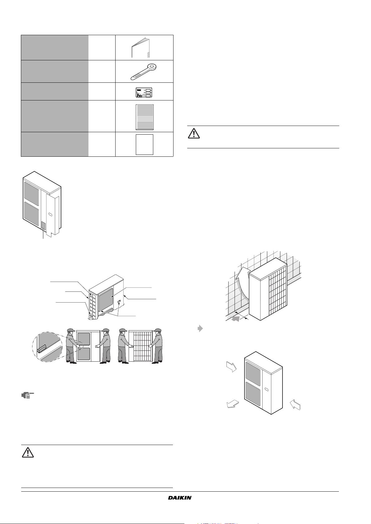
Accessories
Check if the following accessories are included with the unit
Installation manual 1
Clamp 2
Fluorinated greenhouse gases
label
Multilingual fluorinated
greenhouse gases label
CE-Declaration of conformity 1
See the figure below for the location of the accessories.
1 Accessories
1
1
1
1
Select an installation site where the following conditions are
satisfied and that meets with your customer’s approval.
- Places which are well-ventilated.
- Places where the unit does not bother next-door neighbours.
- Safe places which can withstand the unit’s weight and
vibration and where the unit can be installed level.
- Places where there is no possibility of flammable gas or
product leak.
- The appliance shall not be placed nor used in a potentially
explosive atmosphere.
- Places where servicing space can be well ensured.
- Places where the indoor and outdoor units’ piping and wiring
lengths come within the allowable ranges.
- Places where water leaking from the unit cannot cause
damage to the location (e.g. in case of a blocked drain pipe).
- Places where the rain can be avoided as much as possible.
This is a class A product. In a domestic environment this
product may cause radio interference in which case the
user may be required to take adequate measures.
2
When installing the unit in a place exposed to strong wind, pay
special attention to the following.
Strong winds of 5 m/sec or more blowing against the outdoor
unit's air outlet causes short circuit (suction of discharge air),
and this may have the following consequences:
- Deterioration of the operational capacity.
- Frequent frost acceleration in heating operation.
- Disruption of operation due to rise of high pressure.
- When a strong wind blows continuously on the face of the
unit, the fan can start rotating very fast until it breaks.
Refer to the figures for installation of this unit in a place where
the wind direction can be foreseen.
■ Turn the air outlet side toward the building's wall, fence or
screen.
Handling
As shown in the figure, bring the unit slowly by grabbing the left and
right grips.
Suction inlet
Corner
Handle
100~140
class models
Do not holding the suction inlet in the side of the casing, otherwise
the casing could be deformed.
(Place your hands on the corner in the case of 71 class model.)
■ Take care not to let hands or objects come in contact
with rear fins.
■ Work in a team of at least two people when carrying
the unit.
Only hold the unit at the specified positions when
carrying it using PP bands or other items.
ELECTING INSTALLATION SITE
S
■ Make sure to provide for adequate measures in order
to prevent that the outdoor unit be used as a shelter
by small animals.
■ Small animals making contact with electrical parts can
cause malfunctions, smoke or fire. Please instruct the
customer to keep the area around the unit clean.
Outlet grille
Outdoor unit
Handle
Make sure there is enough room to do the installation
■ Set the outlet side at a right angle to the direction of the wind.
Strong wind
Blown air Strong wind
3
Prepare a water drainage channel around the foundation, to
drain waste water from around the unit.
4
If the water drainage of the unit is not easy, please build up the
unit on a foundation of concrete blocks, etc. (the height of the
foundation should be maximum 150 mm).
5
If you install the unit on a frame, please install a waterproof plate
within 150 mm of the underside of the unit in order to prevent the
invasion of water from the lower direction.
Installation manual
3
RZQG71, 100, 125, 140LV1B
Split System air conditioners
3P274408-1
6
When installing the unit in a place frequently exposed to snow,
pay special attention to the following:
- Place the outdoor unit on a stand (field supply) so that it is
not covered by snow falls, snow buildups, or snow drifts.
Ensure the bottom plate is at least 500 mm higher than
expected snow levels.
- Install a roof cover for a snow fence or other enclosure (field
supply).
- Remove the rear suction grille to prevent snow from
accumulating on the rear fins.
- Avoid installing the unit in a location where blown snow will
build up.
Also take the following measures, as there is a danger the
drainage discharged during defrosting operation may freeze.
- Install the outdoor unit at a sufficient height so that its bottom
plate is above expected snow levels. This is to prevent the
buildup of ice on the underside of the bottom plate. (A space
of at least 500 mm is recommended.)
- Do not use a centralized drain plug (option). (There is a
danger of freezing when a drain plug or drain pipe is used.)
- If there is a problem with dripping of drainage, take a
measure such as positioning a roof cover (field supply) under
the outdoor unit.
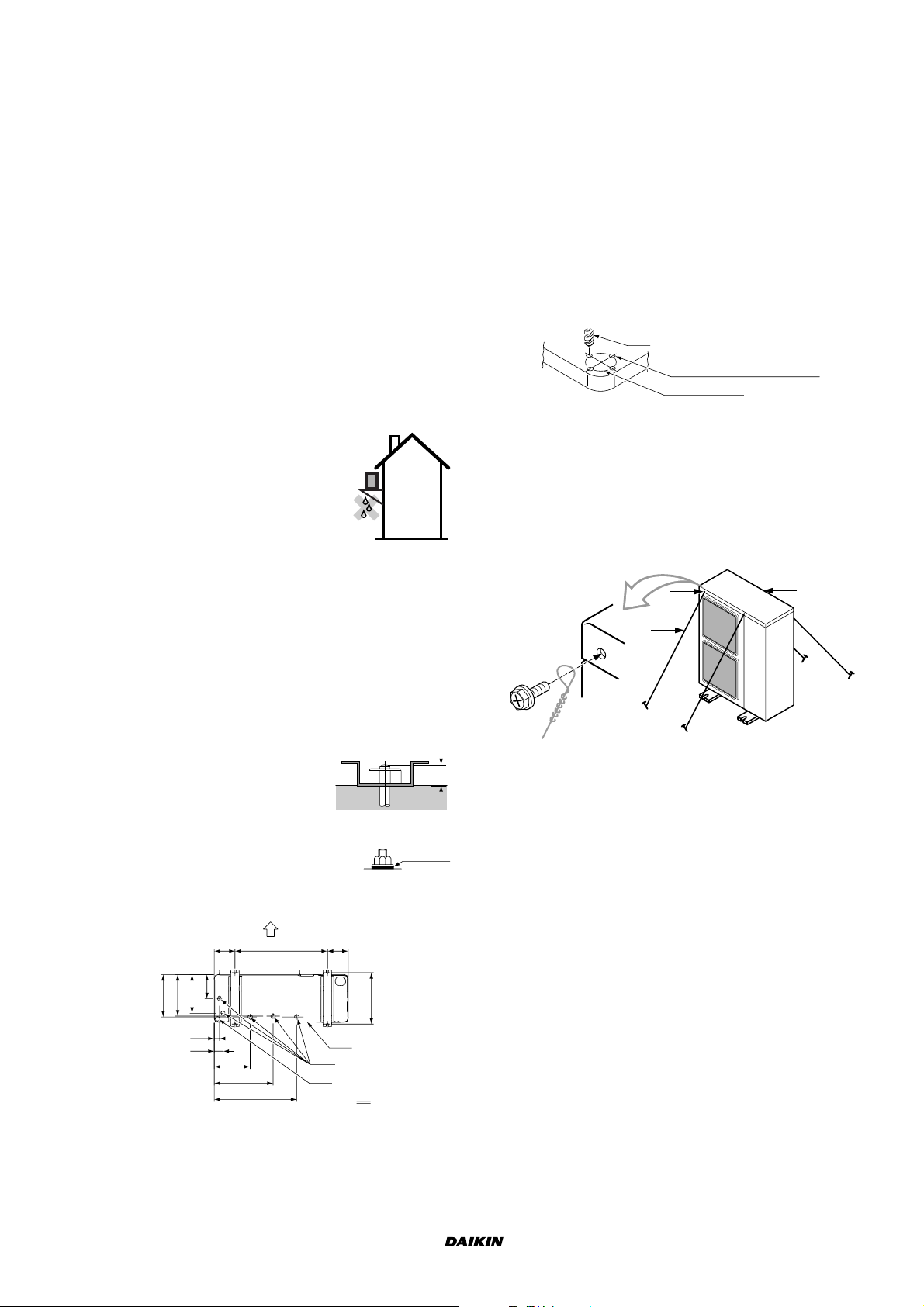
7
If you install the unit on a building frame,
please install a waterproof plate (within
150 mm of the underside of the unit) or
use a drain plug kit (option) in order to
avoid the drainwater dripping. (See
figure.)
RECAUTIONS ON INSTALLATION
P
Installation method on the foundation
Drain pipe disposal
■ Potentially problematic locations for outdoor unit drainage
In locations where, for example, drainage may fall on passersby
or frozen drainage may cause passersby to slip over, install an
enclosure (field supply) to prevent people approaching the
outdoor unit.
■ In regions where buildups of snow can be expected, the
accumulation and freezing of snow in the space between the
heat exchanger and external plate may lower operating
efficiency. In this case, drill a knockout hole in the lower part of
the bottom frame so the snow can escape. When creating a
knockout hole, use a
connected to the circumference of the knockout hole (4 places).
■ After punching the knockout hole, the application of repair-type
paint on the surface around the edge sections is recommended
to prevent rust.
6 mm drill bit to open round holes
Ø
Drill
Area around knockout hole
Knockout hole
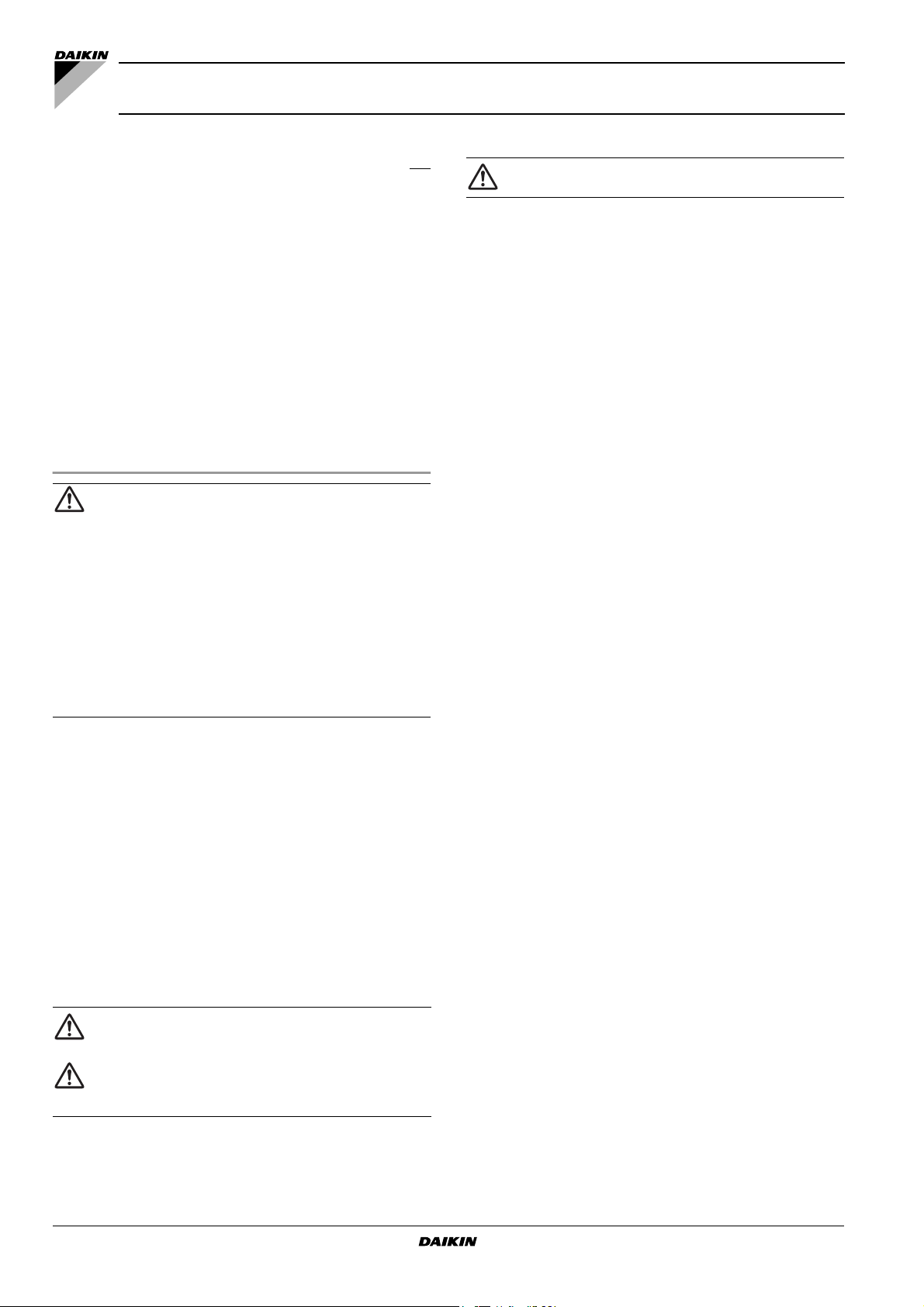
Installation method for prevention of falling over
If it is necessary to prevent the unit from falling over, install as shown
in the figure.
■ prepare all 4 wires as indicated in the drawing
■ unscrew the top plate at the 4 locations indicated A and B
■ put the screws through the nooses and screw them back tight
AA
B
■ Check the strength and level of the installation ground so that
the unit will not cause any operating vibration or noise after
installation.
■ In accordance with the foundation drawing in the figure, fix the
unit securely by means of the foundation bolts. (Prepare four
sets of M12 foundation bolts, nuts and washers each which are
available on the market.)
■ It is best to screw in the foundation
bolts until their length are 20 mm from
the foundation surface.
■ Fix the outdoor unit to the foundation
bolts using nuts with resin washers. (Refer
to the right-hand drawing.)
If the coating on the fastening area is
stripped off, the nuts rust easily.
Resin
washers
20
A
160 160
620
B
161
285
279
260
36
61
262
416
595
A Front (Air outlet side) D Drain hole
B Leg pitch E Knockout hole
C Bottom frame F Bottom view (mm)
E
B
(345~355)
C
D
F
C
A location of the 2 fixation holes on the front side of the unit
B location of the 2 fixation holes on the rear side of the unit
C wires: field supply
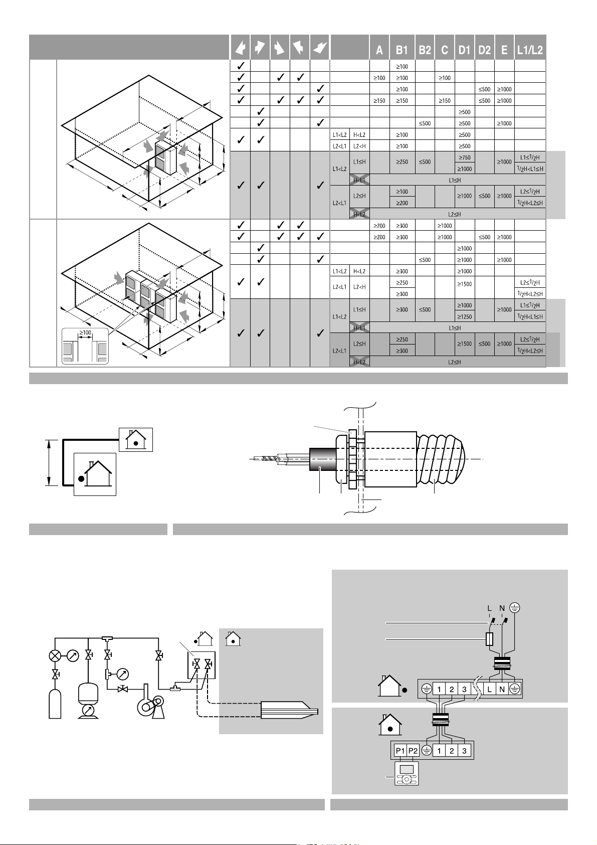
NSTALLATION SERVICING SPACE
I
■ The installation service spaces shown in these drawings are
based on an outdoor unit intake area temperature of 35°C (DB)
for COOL operation. If the planned intake area temperature
exceeds 35°C (DB), or if the heat load of all outdoor units is
increased significantly and exceeds the maximum operating
capacity, secure a larger space than that indicated by the intake
dimensions in these drawings.
■ For installation, consider both pedestrian and airflow paths and
choose a suitable pattern from these drawings to match the
space available onsite. (If the number of units to be installed
exceeds the patterns in these drawings, consider using shortcircuits.)
■ Regarding the front space, position the units with consideration
to the space required for the onsite refrigerant piping work.
(Consult your dealer if the work conditions do not match those in
the drawings.)
RZQG71, 100, 125, 140LV1B
Split System air conditioners
3P274408-1
Installation manual
4
 Loading...