

Installer reference guide
Split system air conditioners
RZAG71L7V1B
RZAG100L7V1B
RZAG125L7V1B
RZAG140L7V1B
Installer reference guide
Split system air conditioners
English

Table of Contents
Table of Contents
1 General safety precautions 2
1.1 About the documentation .......................................................... 2
1.1.1 Meaning of warnings and symbols.............................. 3
1.2 For the installer.......................................................................... 3
1.2.1 General ....................................................................... 3
1.2.2 Installation site ............................................................ 3
1.2.3 Refrigerant .................................................................. 3
1.2.4 Brine............................................................................ 4
1.2.5 Water .......................................................................... 4
1.2.6 Electrical ..................................................................... 5
2 About the documentation 5
2.1 About this document.................................................................. 5
2.2 Installer reference guide at a glance ......................................... 6
3 About the box 6
3.1 Overview: About the box ........................................................... 6
3.2 Outdoor unit............................................................................... 6
3.2.1 To unpack the outdoor unit ......................................... 6
3.2.2 To handle the outdoor unit.......................................... 6
3.2.3 To remove the accessories from the outdoor unit....... 6
4 About the units and options 7
4.1 Overview: About the units and options...................................... 7
4.2 Identification .............................................................................. 7
4.2.1 Identification label: Outdoor unit ................................. 7
4.3 Combining units and options ..................................................... 7
4.3.1 Possible options for the outdoor unit........................... 7
5 Preparation 7
5.1 Overview: Preparation............................................................... 7
5.2 Preparing installation site .......................................................... 7
5.2.1 Installation site requirements of the outdoor unit ........ 7
5.2.2 Additional installation site requirements of the
outdoor unit in cold climates ....................................... 9
5.2.3 About the minimum floor area..................................... 9
5.3 Preparing refrigerant piping....................................................... 10
5.3.1 Refrigerant piping requirements.................................. 10
5.3.2 Refrigerant piping insulation ....................................... 10
5.4 Preparing electrical wiring ......................................................... 10
5.4.1 About preparing electrical wiring................................. 10
6 Installation 10
6.1 Overview: Installation ................................................................ 10
6.2 Opening the units ...................................................................... 11
6.2.1 About opening the units .............................................. 11
6.2.2 To open the outdoor unit............................................. 11
6.3 Mounting the outdoor unit.......................................................... 11
6.3.1 About mounting the outdoor unit................................. 11
6.3.2 Precautions when mounting the outdoor unit.............. 11
6.3.3 To provide the installation structure............................ 11
6.3.4 To install the outdoor unit............................................ 11
6.3.5 To provide drainage.................................................... 11
6.3.6 To prevent the outdoor unit from falling over .............. 12
6.4 Connecting the refrigerant piping .............................................. 12
6.4.1 About connecting the refrigerant piping ...................... 12
6.4.2 Precautions when connecting the refrigerant piping... 12
6.4.3 Guidelines when connecting the refrigerant piping..... 13
6.4.4 Pipe bending guidelines.............................................. 13
6.4.5 To flare the pipe end................................................... 13
6.4.6 To braze the pipe end................................................. 13
6.4.7 Using the stop valve and service port......................... 14
6.4.8 To connect the refrigerant piping to the outdoor unit .. 14
6.4.9 To determine if oil traps are required.......................... 15
6.5 Checking the refrigerant piping ................................................. 16
6.5.1 About checking the refrigerant piping ......................... 16
6.5.2 Precautions when checking the refrigerant piping ....... 16
6.5.3 Checking refrigerant piping: Setup............................... 16
6.5.4 To check for leaks........................................................ 16
6.5.5 To perform vacuum drying ........................................... 16
6.6 Charging refrigerant ................................................................... 17
6.6.1 About charging refrigerant ........................................... 17
6.6.2 About the refrigerant .................................................... 17
6.6.3 Precautions when charging refrigerant ........................ 18
6.6.4 To determine the additional refrigerant amount........... 18
6.6.5 To determine the complete recharge amount.............. 18
6.6.6 Charging refrigerant: Setup.......................................... 18
6.6.7 To charge refrigerant ................................................... 18
6.6.8 To fix the fluorinated greenhouse gases label ............. 18
6.7 Connecting the electrical wiring.................................................. 19
6.7.1 About connecting the electrical wiring.......................... 19
6.7.2 About electrical compliance ......................................... 19
6.7.3 Precautions when connecting the electrical wiring ...... 19
6.7.4 Guidelines when connecting the electrical wiring ........ 19
6.7.5 Specifications of standard wiring components............. 19
6.7.6 To connect the electrical wiring on the outdoor unit..... 19
6.8 Finishing the outdoor unit installation ......................................... 20
6.8.1 To finish the outdoor unit installation ........................... 20
6.8.2 To close the outdoor unit ............................................. 20
6.8.3 To check the insulation resistance of the compressor. 21
7 Commissioning 21
7.1 Overview: Commissioning.......................................................... 21
7.2 Precautions when commissioning .............................................. 21
7.3 Checklist before commissioning................................................. 21
7.4 To perform a test run.................................................................. 22
7.5 Error codes when performing a test run ..................................... 22
8 Hand-over to the user 23
9 Maintenance and service 23
9.1 Overview: Maintenance and service .......................................... 23
9.2 Maintenance safety precautions................................................. 23
9.3 Checklist for yearly maintenance of the outdoor unit ................. 23
10 Troubleshooting 23
10.1 Overview: Troubleshooting......................................................... 23
10.2 Precautions when troubleshooting ............................................. 23
11 Disposal 23
11.1 Overview: Disposal..................................................................... 23
11.2 About pump down ...................................................................... 24
11.3 To pump down............................................................................ 24
12 Technical data 25
12.1 Overview: Technical data ........................................................... 25
12.2 Dimensions: Outdoor unit ........................................................... 25
12.3 Service space: Outdoor unit ....................................................... 27
12.4 Components: Outdoor unit ......................................................... 29
12.5 Piping diagram: Outdoor unit...................................................... 31
12.6 Wiring diagram: Outdoor unit ..................................................... 32
12.7 Technical specifications: Outdoor unit........................................ 36
13 Glossary 38
1 General safety precautions
1.1 About the documentation
▪ The original documentation is written in English. All other
languages are translations.
▪ The precautions described in this document cover very important
topics, follow them carefully.
Installer reference guide
2
RZAG71~140L7V1B
Split system air conditioners
4P418663-1 – 2016.02
1 General safety precautions
▪ The installation of the system, and all activities described in the
installation manual and the installer reference guide must be
performed by an authorized installer.
1.1.1 Meaning of warnings and symbols
DANGER
Indicates a situation that results in death or serious injury.
DANGER: RISK OF ELECTROCUTION
Indicates a situation that could result in electrocution.
DANGER: RISK OF BURNING
Indicates a situation that could result in burning because of
extreme hot or cold temperatures.
WARNING: FLAMMABLE MATERIAL
WARNING
Indicates a situation that could result in death or serious
injury.
CAUTION
Indicates a situation that could result in minor or moderate
injury.
NOTICE
Indicates a situation that could result in equipment or
property damage.
INFORMATION
Indicates useful tips or additional information.
1.2 For the installer
1.2.1 General
If you are not sure how to install or operate the unit, contact your
dealer.
NOTICE
Improper installation or attachment of equipment or
accessories could result in electric shock, short-circuit,
leaks, fire or other damage to the equipment. Only use
accessories, optional equipment and spare parts made or
approved by Daikin.
WARNING
Make sure installation, testing and applied materials
comply with applicable legislation (on top of the
instructions described in the Daikin documentation).
CAUTION
Wear adequate personal protective equipment (protective
gloves, safety glasses,…) when installing, maintaining or
servicing the system.
WARNING
Tear apart and throw away plastic packaging bags so that
nobody, especially children, can play with them. Possible
risk: suffocation.
DANGER: RISK OF BURNING
▪ Do NOT touch the refrigerant piping, water piping or
internal parts during and immediately after operation. It
could be too hot or too cold. Give it time to return to
normal temperature. If you must touch it, wear
protective gloves.
▪ Do NOT touch any accidental leaking refrigerant.
WARNING
Provide adequate measures to prevent that the unit can be
used as a shelter by small animals. Small animals that
make contact with electrical parts can cause malfunctions,
smoke or fire.
CAUTION
Do NOT touch the air inlet or aluminum fins of the unit.
NOTICE
▪ Do NOT place any objects or equipment on top of the
unit.
▪ Do NOT sit, climb or stand on the unit.
NOTICE
Works executed on the outdoor unit are best done under
dry weather conditions to avoid water ingress.
In accordance with the applicable legislation, it might be necessary
to provide a logbook with the product containing at least: information
on maintenance, repair work, results of tests, stand-by periods,…
Also, at least, following information must be provided at an
accessible place at the product:
▪ Instructions for shutting down the system in case of an emergency
▪ Name and address of fire department, police and hospital
▪ Name, address and day and night telephone numbers for
obtaining service
In Europe, EN378 provides the necessary guidance for this logbook.
1.2.2 Installation site
▪ Provide sufficient space around the unit for servicing and air
circulation.
▪ Make sure the installation site withstands the unit's weight and
vibration.
▪ Make sure the area is well ventilated. Do NOT block any
ventilation openings.
▪ Make sure the unit is level.
Do NOT install the unit in the following places:
▪ In potentially explosive atmospheres.
▪ In places where there is machinery that emits electromagnetic
waves. Electromagnetic waves may disturb the control system,
and cause malfunction of the equipment.
▪ In places where there is a risk of fire due to the leakage of
flammable gases (example: thinner or gasoline), carbon fibre,
ignitable dust.
▪ In places where corrosive gas (example: sulphurous acid gas) is
produced. Corrosion of copper pipes or soldered parts may cause
the refrigerant to leak.
RZAG71~140L7V1B
Split system air conditioners
4P418663-1 – 2016.02
1.2.3 Refrigerant
If applicable. See the installation manual or installer reference guide
of your application for more information.
Installer reference guide
3
1 General safety precautions
NOTICE
Make sure refrigerant piping installation complies with
applicable legislation. In Europe, EN378 is the applicable
standard.
NOTICE
Make sure the field piping and connections are not
subjected to stress.
WARNING
During tests, NEVER pressurize the product with a
pressure higher than the maximum allowable pressure (as
indicated on the nameplate of the unit).
WARNING
Take sufficient precautions in case of refrigerant leakage. If
refrigerant gas leaks, ventilate the area immediately.
Possible risks:
▪ Excessive refrigerant concentrations in a closed room
can lead to oxygen deficiency.
▪ Toxic gas may be produced if refrigerant gas comes
into contact with fire.
WARNING
Always recover the refrigerant. Do NOT release them
directly into the environment. Use a vacuum pump to
evacuate the installation.
NOTICE
After all the piping has been connected, make sure there is
no gas leak. Use nitrogen to perform a gas leak detection.
NOTICE
▪ To avoid compressor breakdown, do NOT charge more
than the specified amount of refrigerant.
▪ When the refrigerant system is to be opened,
refrigerant must be treated according to the applicable
legislation.
WARNING
Make sure there is no oxygen in the system. Refrigerant
may only be charged after performing the leak test and the
vacuum drying.
▪ In case re-charge is required, refer to the nameplate of the unit. It
states the type of refrigerant and necessary amount.
▪ The unit is factory charged with refrigerant and depending on pipe
sizes and pipe lengths some systems require additional charging
of refrigerant.
▪ Only use tools exclusively for the refrigerant type used in the
system, this to ensure pressure resistance and prevent foreign
materials from entering into the system.
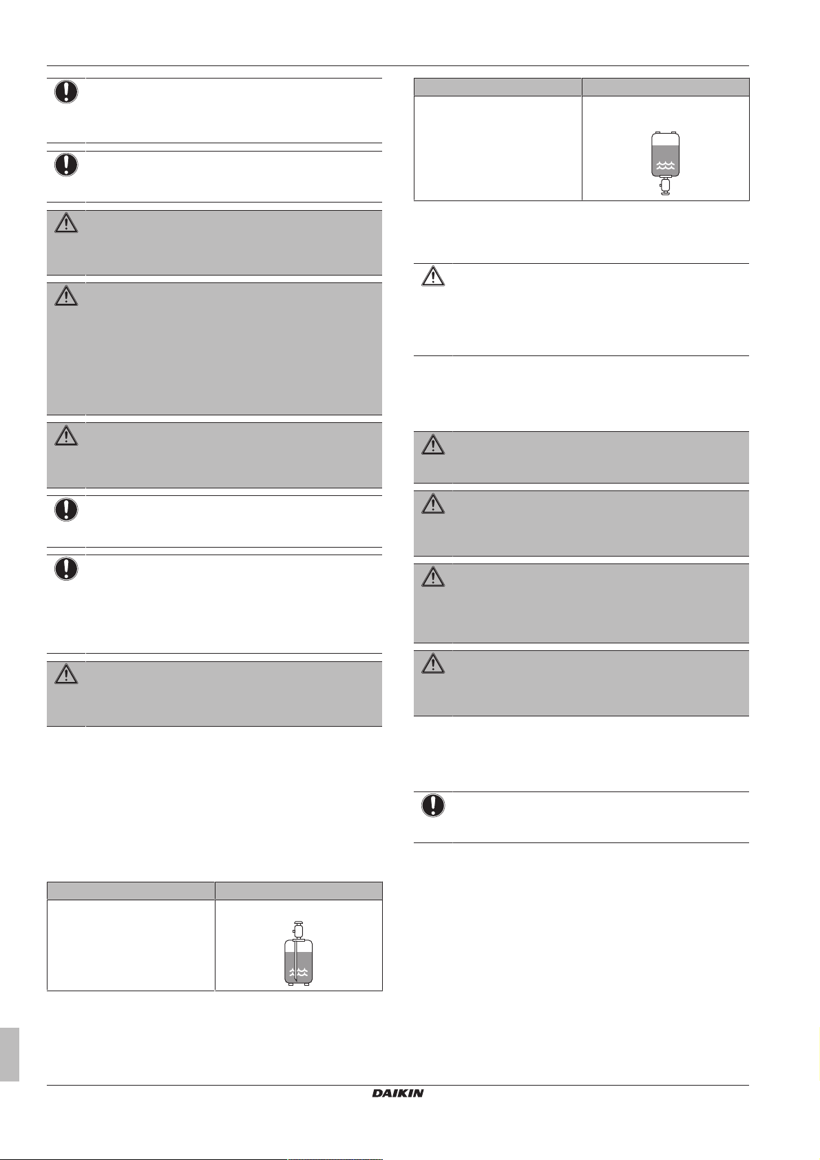
▪ Charge the liquid refrigerant as follows:
If Then
A siphon tube is NOT present Charge with the cylinder upside
down.
▪ Open refrigerant cylinders slowly.
▪ Charge the refrigerant in liquid form. Adding it in gas form may
prevent normal operation.
CAUTION
When the refrigerant charging procedure is done or when
pausing, close the valve of the refrigerant tank
immediately. If the valve is not closed immediately,
remaining pressure might charge additional refrigerant.
Possible consequence: Incorrect refrigerant amount.
1.2.4 Brine
If applicable. See the installation manual or installer reference guide
of your application for more information.
WARNING
The selection of the brine MUST be in accordance with the
applicable legislation.
WARNING
Take sufficient precautions in case of brine leakage. If
brine leaks, ventilate the area immediately and contact
your local dealer.
WARNING
The ambient temperature inside the unit can get much
higher than that of the room, e.g. 70°C. In case of a brine
leak, hot parts inside the unit can create a hazardous
situation.
WARNING
The use and installation of the application MUST comply
with the safety and environmental precautions specified in
the applicable legislation.
1.2.5 Water
If applicable. See the installation manual or installer reference guide
of your application for more information.
NOTICE
Make sure water quality complies with EU directive
98/83EC.
If Then
A siphon tube is present
(i.e., the cylinder is marked with
"Liquid filling siphon attached")
Installer reference guide
4
Charge with the cylinder upright.
RZAG71~140L7V1B
Split system air conditioners
4P418663-1 – 2016.02
2 About the documentation
1.2.6 Electrical
DANGER: RISK OF ELECTROCUTION
▪ Turn OFF all power supply before removing the
switch box cover, connecting electrical wiring or
touching electrical parts.
▪ Disconnect the power supply for more than 1 minute,
and measure the voltage at the terminals of main circuit
capacitors or electrical components before servicing.
The voltage MUST be less than 50 V DC before you
can touch electrical components. For the location of the
terminals, see the wiring diagram.
▪ Do NOT touch electrical components with wet hands.
▪ Do NOT leave the unit unattended when the service
cover is removed.
WARNING
If NOT factory installed, a main switch or other means for
disconnection, having a contact separation in all poles
providing full disconnection under overvoltage category III
condition, shall be installed in the fixed wiring.
WARNING
▪ ONLY use copper wires.
▪ Make sure the field wiring complies with the applicable
legislation.
▪ All field wiring must be performed in accordance with
the wiring diagram supplied with the product.
▪ NEVER squeeze bundled cables and make sure they
do not come in contact with the piping and sharp
edges. Make sure no external pressure is applied to the
terminal connections.
▪ Make sure to install earth wiring. Do NOT earth the unit
to a utility pipe, surge absorber, or telephone earth.
Incomplete earth may cause electrical shock.
▪ Make sure to use a dedicated power circuit. NEVER
use a power supply shared by another appliance.
▪ Make sure to install the required fuses or circuit
breakers.
▪ Make sure to install an earth leakage protector. Failure
to do so may cause electric shock or fire.
▪ When installing the earth leakage protector, make sure
it is compatible with the inverter (resistant to high
frequency electric noise) to avoid unnecessary opening
of the earth leakage protector.
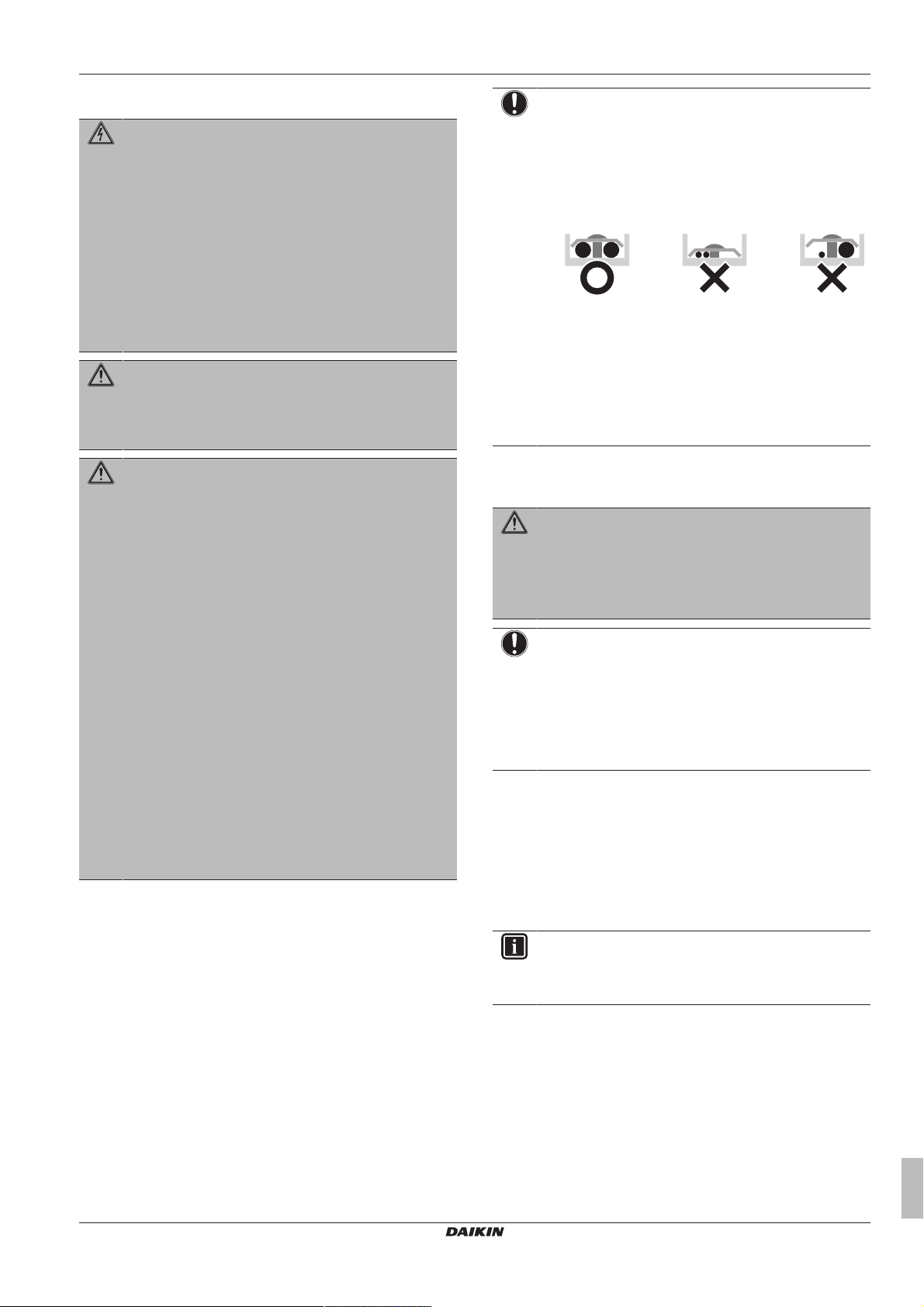
NOTICE
Precautions when laying power wiring:
▪ Do not connect wiring of different thicknesses to the
power terminal block (slack in the power wiring may
cause abnormal heat).
▪ When connecting wiring which is the same thickness,
do as shown in the figure below.
▪ For wiring, use the designated power wire and connect
firmly, then secure to prevent outside pressure being
exerted on the terminal board.
▪ Use an appropriate screwdriver for tightening the
terminal screws. A screwdriver with a small head will
damage the head and make proper tightening
impossible.
▪ Over-tightening the terminal screws may break them.
Install power cables at least 1 metre away from televisions or radios
to prevent interference. Depending on the radio waves, a distance of
1metre may not be sufficient.
WARNING
▪ After finishing the electrical work, confirm that each
electrical component and terminal inside the electrical
components box is connected securely.
▪ Make sure all covers are closed before starting up the
unit.
NOTICE
Only applicable if the power supply is three‑phase, and the
compressor has an ON/OFF starting method.
If there exists the possibility of reversed phase after a
momentary black out and the power goes on and off while
the product is operating, attach a reversed phase
protection circuit locally. Running the product in reversed
phase can break the compressor and other parts.
2 About the documentation
2.1 About this document
Target audience
Authorised installers
RZAG71~140L7V1B
Split system air conditioners
4P418663-1 – 2016.02
INFORMATION
This appliance is intended to be used by expert or trained
users in shops, in light industry and on farms, or for
commercial use by lay persons.
Documentation set
This document is part of a documentation set. The complete set
consists of:
▪ General safety precautions:
▪ Safety instructions that you must read before installing
▪ Format: Paper (in the box of the outdoor unit)
▪ Outdoor unit installation manual:
▪ Installation instructions
▪ Format: Paper (in the box of the outdoor unit)
Installer reference guide
5
3 About the box
21
1×
2
1
a
1×
b
1×
c
2×
d
1×
e
1×
ENERG
IJAY
IAIE
ENERG
IJAY
IAIE
▪ Installer reference guide:
▪ Preparation of the installation, technical specifications,
reference data,…
▪ Format: Digital files on http://www.daikineurope.com/support-
and-manuals/product-information/
Latest revisions of the supplied documentation may be available on
the regional Daikin website or via your dealer.
The original documentation is written in English. All other languages
are translations.
2.2 Installer reference guide at a glance
Chapter Description
General safety
precautions
About the documentation What documentation exists for the
About the box How to unpack the units and remove
About the units and
options
Preparation What to do and know before going
Installation What to do and know to install the
Commissioning What to do and know to commission the
Hand‑over to the user What to give and explain to the user
Maintenance and service How to maintain and service the units
Troubleshooting What to do in case of problems
Disposal How to dispose of the system
Technical data Specifications of the system
Glossary Definition of terms
Safety instructions that you must read
before installing
installer
their accessories
▪ How to identify the units
▪ Possible combinations of units and
options
on‑site
system
system after it is installed
3.2 Outdoor unit
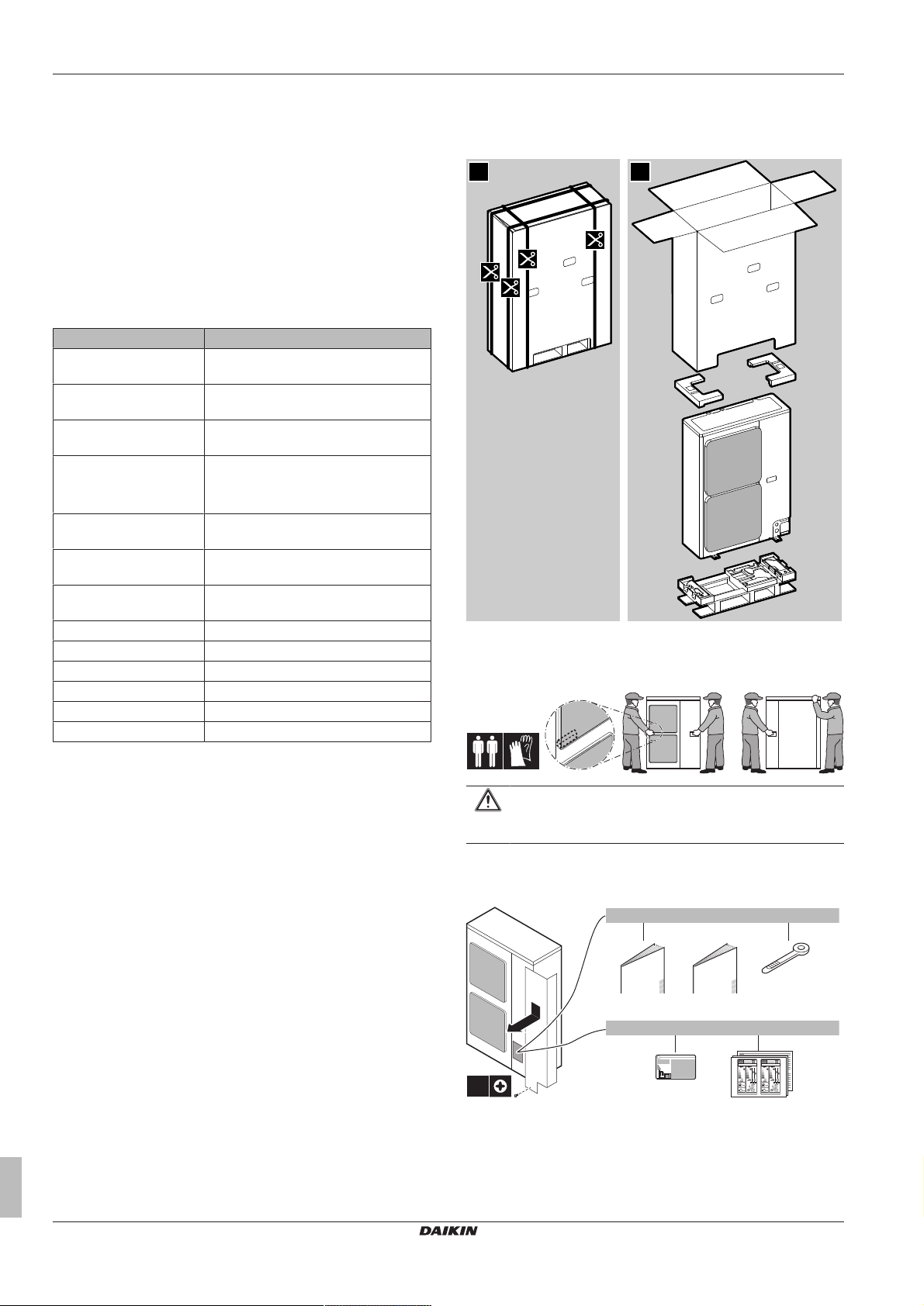
3.2.1 To unpack the outdoor unit
3.2.2 To handle the outdoor unit
Carry the unit slowly as shown:
3 About the box
3.1 Overview: About the box
This chapter describes what you have to do after the box with the
outdoor unit is delivered on-site.
It contains information about:
▪ Unpacking and handling the units
▪ Removing the accessories from the units
Keep the following in mind:
▪ At delivery, the unit must be checked for damage. Any damage
must be reported immediately to the carrier's claims agent.
▪ Bring the packed unit as close as possible to its final installation
position to prevent damage during transport.
Installer reference guide
6
CAUTION
To avoid injury, do NOT touch the air inlet or aluminum fins
of the unit.
3.2.3 To remove the accessories from the outdoor unit
a General safety precautions
b Outdoor unit installation manual
c Cable tie
d Fluorinated greenhouse gases label
e Energy label
RZAG71~140L7V1B
Split system air conditioners
4P418663-1 – 2016.02

4 About the units and options
4 About the units and options
4.1 Overview: About the units and options
This chapter contains information about:
▪ Identifying the outdoor unit
▪ Combining the outdoor unit with options
INFORMATION
For year‑round cooling applications with low indoor
humidity conditions, such as Electronic Data Processing
rooms, contact your dealer or see the engineering
databook or the service manual.
4.2 Identification
NOTICE
When installing or servicing several units at the same time,
make sure NOT to switch the service panels between
different models.
4.2.1 Identification label: Outdoor unit
Location
▪ If you install EKBPH140L7 in combination with RZAG71, you also
have to install the demand adaptor kit.
▪ For installation instructions, see the installation manual of the
bottom plate heater.
Demand adaptor kit (SB.KRP58M51)
▪ Can be used for the following:
▪ Low noise: To lower the operation sound of the outdoor unit.
▪ I-demand function: To limit the power consumption from the
system (example: budget control, limit power consumption
during peak moments…).
▪ In combination with a bottom plate heater (see above)(only for
RZAG71).
▪ For installation instructions, see the installation manual of the
demand adaptor kit.
5 Preparation
5.1 Overview: Preparation
This chapter describes what you have to do and know before going
on-site.
It contains information about:
▪ Preparing the installation site
▪ Preparing the refrigerant piping
▪ Preparing the electrical wiring
Model identification
RZAG: Contains components (insulation…) to prevent freeze-up in
areas with low ambient temperature and high humidity. Possible to
connect an optional bottom plate heater.
Example: R Z A G 140 L7 V1 B [*]
Code Explanation
R Air-cooled split outdoor unit
Z Inverter
A Refrigerant R32
G GQI-Eco series
71~140 Capacity class
L7 Model series
V1 Power supply
B European market
[*] Minor model change indication
4.3 Combining units and options
5.2 Preparing installation site
Do NOT install the unit in places often used as work place. In case
of construction works (e.g. grinding works) where a lot of dust is
created, the unit must be covered.
Choose the installation location with sufficient place for carrying the
unit in and out of the site.
5.2.1 Installation site requirements of the outdoor unit
INFORMATION
Also read the following requirements:
▪ General installation site requirements. See the
"General safety precautions" chapter.
▪ Service space requirements. See the "Technical data"
chapter.
▪ Refrigerant piping requirements (length, height
difference). See further in this "Preparation" chapter.
CAUTION
Appliance not accessible to the general public, install it in a
secured area, protected from easy access.
This unit, both indoor and outdoor, is suitable for
installation in a commercial and light industrial
environment.
4.3.1 Possible options for the outdoor unit
Bottom plate heater (EKBPH140L7)
▪ Prevents freeze-up of the bottom plate.
▪ Recommended in areas with low ambient temperature and high
humidity.
RZAG71~140L7V1B
Split system air conditioners
4P418663-1 – 2016.02
Installer reference guide
7
5 Preparation
b
a
c
df e
(mm)
≥
1500
≥
1500
≥
1000
≥
1000
b
c
a
a
b
c
d
c
d
a
b
c
b
NOTICE
The equipment described in this manual may cause
electronic noise generated from radio-frequency energy.
The equipment complies to specifications that are
designed to provide reasonable protection against such
interference. However, there is no guarantee that
interference will not occur in a particular installation.
It is therefore recommended to install the equipment and
electric wires keeping proper distances away from stereo
equipment, personal computers, etc.
a Earth leakage protector
b Fuse
c Outdoor unit
d Indoor unit
e User interface
f Personal computer or radio
In places with weak reception, keep distances of 3m or more to
avoid electromagnetic disturbance of other equipment and use
conduit tubes for power and transmission lines.
▪ Select a place where rain can be avoided as much as possible.
▪ Take care that in the event of a water leak, water cannot cause
any damage to the installation space and surroundings.
▪ Choose a location where the hot/cold air discharged from the unit
or the operation noise, will NOT disturb anyone.
▪ Heat exchanger fins are sharp and injury is possible. Choose an
installation location where there is no risk for injury (especially in
areas where children play).
Do NOT install the unit in the following places:
▪ Sound sensitive areas (e.g. near a bedroom and the like), so that
the operation noise will cause no trouble.
Note: If the sound is measured under actual installation
conditions, the measured value might be higher than the sound
pressure level mentioned in Sound spectrum in the data book due
to environmental noise and sound reflections.
INFORMATION
The sound pressure level is less than 70dBA.
▪ In places where a mineral oil mist, spray or vapour may be
present in the atmosphere. Plastic parts may deteriorate and fall
off or cause water leakage.
It is NOT recommended to install the unit in the following places
because it may shorten the life of the unit:
▪ Where the voltage fluctuates a lot
▪ In vehicles or vessels
▪ Where acidic or alkaline vapour is present
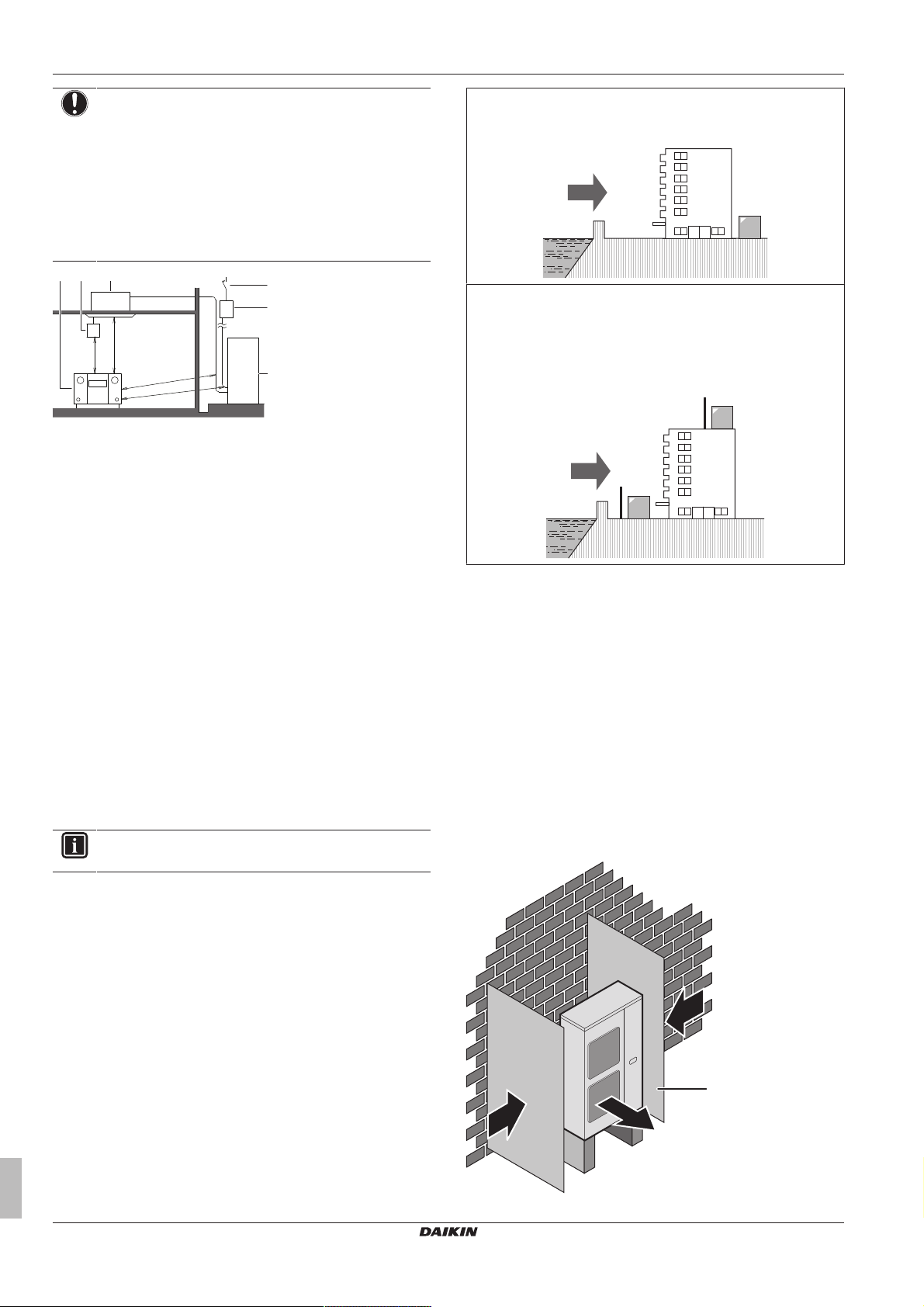
Seaside installation. Make sure the outdoor unit is NOT directly
exposed to sea winds. This is to prevent corrosion caused by high
levels of salt in the air, which might shorten the life of the unit.
Install the outdoor unit away from direct sea winds.
Example: Behind the building.
If the outdoor unit is exposed to direct sea winds, install a
windbreaker.
▪ Height of windbreaker≥1.5×height of outdoor unit
▪ Mind the service space requirements when installing the
windbreaker.
a Sea wind
b Building
c Outdoor unit
d Windbreaker
Strong winds (≥18 km/h) blowing against the outdoor unit’s air outlet
causes short circuit (suction of discharge air). This may result in:
▪ deterioration of the operational capacity;
▪ frequent frost acceleration in heating operation;
▪ disruption of operation due to decrease of low pressure or
increase of high pressure;
▪ a broken fan (if a strong wind blows continuously on the fan, it
may start rotating very fast, until it breaks).
It is recommended to install a baffle plate when the air outlet is
exposed to wind.
It is recommended to install the outdoor unit with the air inlet facing
the wall and NOT directly exposed to the wind.
Installer reference guide
8
a Baffle plate
RZAG71~140L7V1B
Split system air conditioners
4P418663-1 – 2016.02
b Prevailing wind direction
a
b
c
c
d
m [kg]
0
10
20
30
40
50
60
70
80
90
100
110
120
130
140
150
160
170
180
190
200
210
220
230
240
250
260
270
280
290
300
310
320
330
340
350
360
370
380
390
400
410
420
430
440
450
460
470
480
490
500
510
520
530
540
550
1
1.2
1.4
1.6
1.822.2
2.4
2.6
2.833.2
3.4
3.6
3.844.2
4.4
4.6
4.855.2
5.4
5.6
5.866.2
6.4
6.6
6.877.2
7.4
7.6
7.8
8
A
min
[m2]
Floor-standing unit
(c)
Wall-mounted unit
(b)
Ceiling-mounted unit
(a)
Ceiling-mounted
unit
(a)
—
4.6 13.5
<1.224
<1.224 —
4.6 182
1.224 0.956
4.8 14.7
1.224 12.9
4.8 198
1.4 1.25
5.0 16.0
1.4 16.8
5.0 215
1.6 1.63
5.2 17.3
1.6 22.0
5.2 232
1.8 2.07
5.4 18.6
1.8 27.8
5.4 250
2.0 2.55
5.6 20.0
2.0 34.3
5.6 269
2.2 3.09
5.8 21.5
2.2 41.5
5.8 289
2.4 3.68
6.0 23.0
2.4 49.4
6.0 309
2.6 4.31
6.2 24.5
2.6 58.0
6.2 330
2.8 5.00
6.4 26.1
2.8 67.3
6.4 351
3.0 5.74
6.6 27.8
3.0 77.2
6.6 374
3.2 6.54
6.8 29.5
3.2 87.9
6.8 397
3.4 7.38
7.0 31.3
3.4 99.2
7.0 420
3.6 8.27
7.2 33.1
3.6 111
7.2 445
3.8 9.22
7.4 34.9
3.8 124
7.4 470
4.0 10.2
7.6 36.9
4.0 137
7.6 496
4.2 11.3
7.8 38.8
4.2 151
7.8 522
4.4 12.4
8.0 40.8
4.4 166
8.0 549
m [kg]
A
min
[m2]
<1.224 —
4.6 20.2
1.224 1.43
4.8 22.0
1.4 1.87
5.0 23.8
1.6 2.44
5.2 25.8
1.8 3.09
5.4 27.8
2.0 3.81
5.6 29.9
2.2 4.61
5.8 32.1
2.4 5.49
6.0 34.3
2.6 6.44
6.2 36.6
2.8 7.47
6.4 39.1
3.0 8.58
6.6 41.5
3.2 9.76
6.8 44.1
3.4 11.0
7.0 46.7
3.6 12.4
7.2 49.4
3.8 13.8
7.4 52.2
4.0 15.3
7.6 55.1
4.2 16.8
7.8 58.0
4.4 18.5
8.0 61.0
Wall-mounted
unit
(b)
m [kg]
A
min
[m2]
Floor-standing
unit
(c)
m [kg]
A
min
[m2]
c Air outlet
The outdoor unit is designed for outdoor installation only, and for
ambient temperatures ranging:
Model Cooling Heating
RZAG –15~50°CDB –20~15.5°CWB
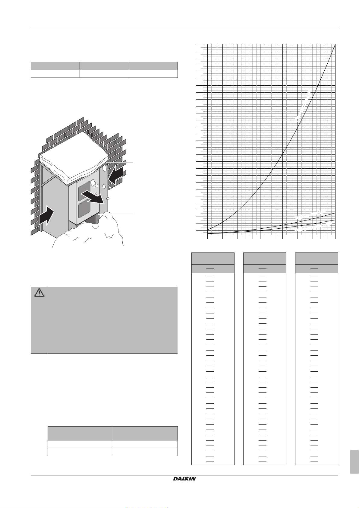
5.2.2 Additional installation site requirements of the outdoor unit in cold climates
Protect the outdoor unit against direct snowfall and take care that the
outdoor unit is NEVER snowed up.
5 Preparation
a Snow cover or shed
b Pedestal (minimum height = 150mm)
c Prevailing wind direction
d Air outlet
5.2.3 About the minimum floor area
WARNING
If appliances contain R32 refrigerant, then the floor area of
the room in which the appliances are installed, operated
and stored must be larger than the minimum floor area.
This applies to:
▪ Indoor units
▪ Outdoor units installed or stored indoors (example:
winter garden, garage, machinery room)
▪ Field piping in unventilated spaces
To determine the minimum floor area
1 Determine the total refrigerant charge in the system (= factory
refrigerant charge + additional refrigerant amount charged).
2 Determine which graph or table to use.
▪ For indoor units: Is the unit ceiling-mounted, wall-mounted or
▪ For outdoor units installed or stored indoors, and field piping
floor-standing?
in unventilated spaces, this depends on the installation
height:
If the installation height
3 Use the graph or table to determine the minimum floor area.
is…
<1.8m Floor-standing units
≥1.8m Wall-mounted units
RZAG71~140L7V1B
Split system air conditioners
4P418663-1 – 2016.02
Then use the graph or
table for…
Installer reference guide
9
6 Installation
t
Ø
H1
L1
m Total refrigerant charge in the system
A
Minimum floor area
min
(a) Ceiling-mounted unit (=Ceiling-mounted unit)
(b) Wall-mounted unit (=Wall-mounted unit)
(c) Floor-standing unit (=Floor-standing unit)
5.3 Preparing refrigerant piping
5.3.1 Refrigerant piping requirements
INFORMATION
Also read the precautions and requirements in the
"General safety precautions" chapter.
Refrigerant piping material
▪ Piping material: Phosphoric acid deoxidised seamless copper.
▪ Piping temper grade and thickness:
Outer diameter
(Ø)
9.5mm (3/8") Annealed (O) ≥0.8mm
15.9mm (5/8") Annealed (O) ≥1.0mm
(a) Depending on the applicable legislation and the unit's
▪ Flare connections: Only use annealed material.
Temper grade Thickness (t)
maximum working pressure (see "PS High" on the unit
name plate), larger piping thickness might be required.
Refrigerant piping diameter
Use the same diameters as the connections on the outdoor units:
L1 liquid piping Ø9.5mm
L1 gas piping Ø15.9mm
Refrigerant piping length and height difference
The piping length and height difference must comply with the
following requirements:
(a)
5.4 Preparing electrical wiring
5.4.1 About preparing electrical wiring
INFORMATION
Also read the precautions and requirements in the
"General safety precautions" chapter.
INFORMATION
Also read "6.7.5 Specifications of standard wiring
components"on page19.
WARNING
▪ If the power supply has a missing or wrong N-phase,
equipment might break down.
▪ Establish proper earthing. Do NOT earth the unit to a
utility pipe, surge absorber, or telephone earth.
Incomplete earthing may cause electrical shock.
▪ Install the required fuses or circuit breakers.
▪ Secure the electrical wiring with cable ties so that the
cables do NOT come in contact with sharp edges or
piping, particularly on the high-pressure side.
▪ Do NOT use taped wires, stranded conductor wires,
extension cords, or connections from a star system.
They can cause overheating, electrical shock or fire.
▪ Do NOT install a phase advancing capacitor, because
this unit is equipped with an inverter. A phase
advancing capacitor will reduce performance and may
cause accidents.
WARNING
▪ All wiring must be performed by an authorized
electrician and must comply with the applicable
legislation.
▪ Make electrical connections to the fixed wiring.
▪ All components procured on the site and all electrical
construction must comply with the applicable
legislation.
Requirement RZAG71 RZAG100~140
Minimum total one‑way piping
length
Maximum total one‑way piping
length
Height difference between the
indoor unit and the outdoor unit
(a) Parenthesised figure represents the equivalent length.
L1≤55m
(75m)
3m≤L1
(a)
H1≤30m
L1≤85m
(100m)
5.3.2 Refrigerant piping insulation
▪ Use polyethylene foam as insulation material:
▪ with a heat transfer rate between 0.041 and 0.052W/mK (0.035
and 0.045kcal/mh°C)
▪ with a heat resistance of at least 120°C
▪ Insulation thickness
Ambient
temperature
≤30°C 75% to 80% RH 15mm
>30°C ≥80% RH 20mm
Humidity Minimum thickness
WARNING
ALWAYS use multicore cable for power supply cables.
6 Installation
(a)
6.1 Overview: Installation
This chapter describes what you have to do and know on-site to
install the system.
Typical workflow
Installation typically consists of the following stages:
▪ Mounting the outdoor unit.
▪ Mounting the indoor unit (+ decoration panel).
▪ Connecting the refrigerant piping.
▪ Checking the refrigerant piping.
▪ Charging refrigerant.
▪ Connecting the electrical wiring.
▪ Finishing the outdoor installation.
▪ Finishing the indoor installation.
Installer reference guide
10
RZAG71~140L7V1B
Split system air conditioners
4P418663-1 – 2016.02
6 Installation
1×
1
2
(mm)
>150
620
350
(345-355)
4× M12
a
20
a
4× M12
INFORMATION
For installation of the indoor unit (mounting the indoor unit,
connecting the refrigerant piping to the indoor unit,
connecting the electrical wiring to the indoor unit …), see
the installation manual of the indoor unit.
6.2 Opening the units
6.2.1 About opening the units
At certain times, you have to open the unit. Example:
▪ When connecting the refrigerant piping
▪ When connecting the electrical wiring
▪ When maintaining or servicing the unit
DANGER: RISK OF ELECTROCUTION
Do NOT leave the unit unattended when the service cover
is removed.
6.2.2 To open the outdoor unit
DANGER: RISK OF ELECTROCUTION
DANGER: RISK OF BURNING
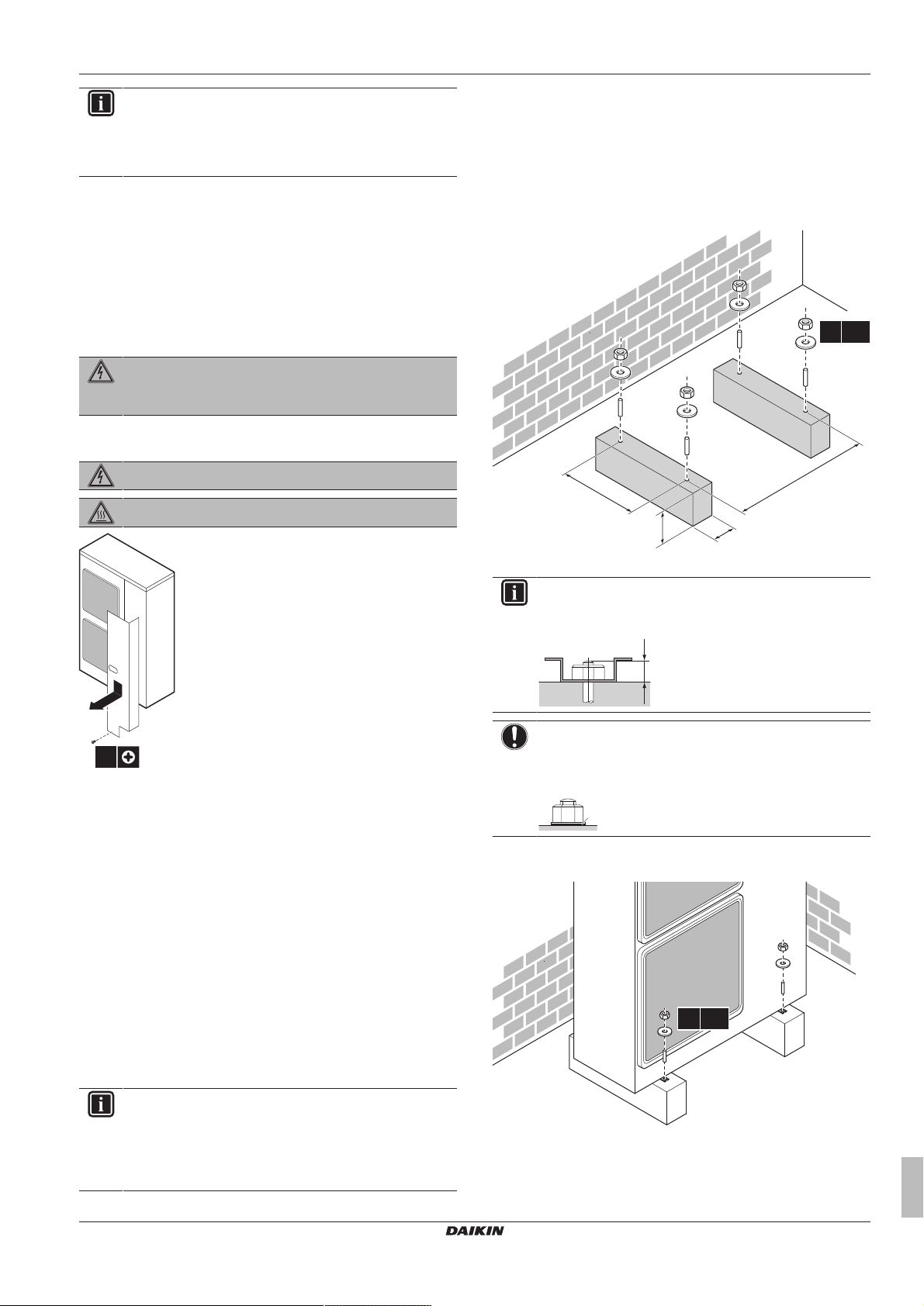
6.3.3 To provide the installation structure
Check the strength and level of the installation ground so that the
unit will not cause any operating vibration or noise.
Fix the unit securely by means of foundation bolts in accordance
with the foundation drawing.
Prepare 4 sets of anchor bolts, nuts and washers (field supply) as
follows:
6.3 Mounting the outdoor unit
6.3.1 About mounting the outdoor unit
Typical workflow
Mounting the outdoor unit typically consists of the following stages:
1 Providing the installation structure.
2 Installing the outdoor unit.
3 Providing drainage.
4 Preventing the outdoor unit from falling over.
5 Protecting the unit against snow and wind by installing a snow
cover and baffle plates. See "Preparing installation site" in
"5Preparation"on page7.
a Make sure not to cover the drain holes.
INFORMATION
The recommended height of the upper protruding part of
the bolts is 20mm.
NOTICE
Fix the outdoor unit to the foundation bolts using nuts with
resin washers (a). If the coating on the fastening area is
stripped off, the nuts rust easily.
6.3.4 To install the outdoor unit
6.3.2 Precautions when mounting the outdoor unit
INFORMATION
Also read the precautions and requirements in the
following chapters:
▪ General safety precautions
▪ Preparation
RZAG71~140L7V1B
Split system air conditioners
4P418663-1 – 2016.02
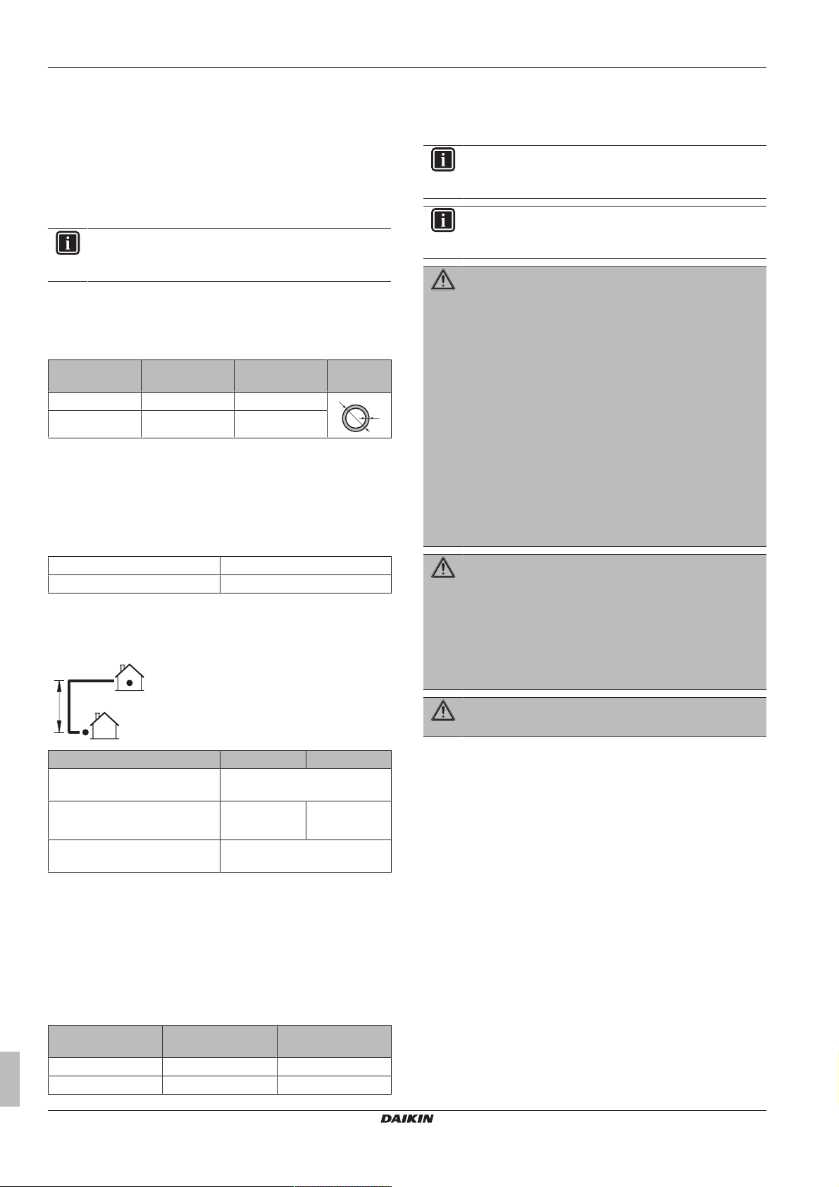
6.3.5 To provide drainage
▪ Make sure that condensation water can be evacuated properly.
Installer reference guide
11
6 Installation
≥150 mm
A
B
B
C
D
E
160 160620
36
61
262
416
595
285
279
260
161
(345~355)
b
a b
4× Ø6 mm
▪ Install the unit on a base to make sure that there is a proper
drainage in order to avoid ice accumulation.
▪ Prepare a water drainage channel around the foundation to drain
waste water surrounding the unit.
▪ Avoid drain water flowing over the footpath, so that it does not
become slippery in case of ambient freezing temperatures.
▪ If you install the unit on a frame, install a waterproof plate within
150 mm of the bottom side of the unit in order to prevent the
invasion of water in the unit and to avoid the drain water dripping
(see the following illustration).
INFORMATION
If necessary, you can use a drain plug kit (field supply) to
prevent drain water from dripping.
NOTICE
If drain holes of the outdoor unit are covered by a mounting
base or by floor surface, raise the unit to provide a free
space of more than 150mm under the outdoor unit.
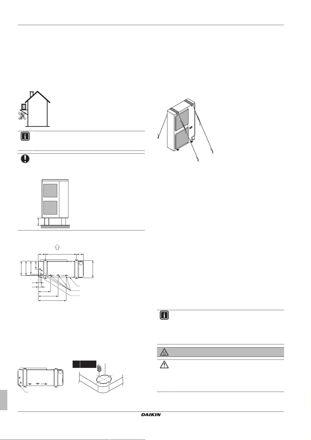
6.3.6 To prevent the outdoor unit from falling over
In case the unit is installed in places where strong wind can tilt the
unit, take following measure:
1 Prepare 2 cables as indicated in the following illustration (field
supply).
2 Place the 2 cables over the outdoor unit.
3 Insert a rubber sheet between the cables and the outdoor unit
to prevent the cable from scratching the paint (field supply).
4 Attach the cable’s ends. Tighten those ends.
6.4 Connecting the refrigerant piping
Drain holes (dimensions in mm)
A Discharge side
B Distance between anchor points
C Bottom frame
D Drain holes
E Knockout hole for snow
Snow
In regions with snowfall, snow might build up and freeze between the
heat exchanger and the external plate. This might decrease the
operating efficiency. To prevent this:
1 Drill (a, 4×) and remove the knockout hole (b).
6.4.1 About connecting the refrigerant piping
Before connecting the refrigerant piping
Make sure the outdoor and indoor unit are mounted.
Typical workflow
Connecting the refrigerant piping involves:
▪ Connecting the refrigerant piping to the outdoor unit
▪ Connecting the refrigerant piping to the indoor unit
▪ Installing oil traps
▪ Insulating the refrigerant piping
▪ Keeping in mind the guidelines for:
▪ Pipe bending
▪ Flaring pipe ends
▪ Brazing
▪ Using the stop valves
6.4.2 Precautions when connecting the refrigerant piping
INFORMATION
Also read the precautions and requirements in the
following chapters:
▪ General safety precautions
▪ Preparation
DANGER: RISK OF BURNING
Installer reference guide
12
2 Remove the burrs, and paint the edges and areas around the
edges using repair paint to prevent rusting.
CAUTION
▪ Do NOT use mineral oil on flared part.
▪ NEVER install a drier to this R32 unit to guarantee its
lifetime. The drying material may dissolve and damage
the system.
RZAG71~140L7V1B
Split system air conditioners
4P418663-1 – 2016.02
 Loading...