

Daikin RXYTQ8U7YF, RXYTQ10U7YF, RXYTQ12U7YF, RXYTQ14U7YF, RXYTQ16U7YF Installer reference guide
Installer and user
reference guide
VRV IV+ heat pump for high ambient temperatures
RXYTQ8U7YF
RXYTQ10U7YF
RXYTQ12U7YF
RXYTQ14U7YF
RXYTQ16U7YF
Installer and user reference guide
VRV IV+ heat pump for high ambient temperatures
English

Table of contents
Table of contents
1 General safety precautions 3
1.1 About the documentation .......................................................... 3
1.1.1 Meaning of warnings and symbols.............................. 3
1.2 For the user ............................................................................... 4
1.3 For the installer.......................................................................... 4
1.3.1 General ....................................................................... 4
1.3.2 Installation site ............................................................ 5
1.3.3 Refrigerant .................................................................. 5
1.3.4 Brine............................................................................ 5
1.3.5 Water .......................................................................... 6
1.3.6 Electrical ..................................................................... 6
2 About the documentation 6
2.1 About this document.................................................................. 6
For the installer 7
3 About the box 7
3.1 Overview: About the box ........................................................... 7
3.2 To unpack the outdoor unit........................................................ 7
3.3 To remove the accessories from the outdoor unit ..................... 8
3.4 Accessory pipes: Diameters...................................................... 8
3.5 To remove the transportation stay............................................. 8
4 About the units and options 8
4.1 Overview: About the units and options...................................... 8
4.2 Identification label: Outdoor unit................................................ 9
4.3 About the outdoor unit ............................................................... 9
4.4 System layout............................................................................ 9
4.5 Combining units and options ..................................................... 9
4.5.1 About combining units and options............................. 9
4.5.2 Possible combinations of indoor units......................... 9
4.5.3 Possible combinations of outdoor units ...................... 9
4.5.4 Possible options for the outdoor unit........................... 10
5 Preparation 10
5.1 Overview: Preparation............................................................... 10
5.2 Preparing the installation site .................................................... 10
5.2.1 Installation site requirements of the outdoor unit ........ 10
5.2.2 Additional installation site requirements of the
outdoor unit in cold climates ....................................... 11
5.2.3 Securing safety against refrigerant leaks.................... 12
5.3 Preparing refrigerant piping....................................................... 13
5.3.1 Refrigerant piping requirements.................................. 13
5.3.2 To select the piping size ............................................. 13
5.3.3 To select refrigerant branch kits.................................. 14
5.3.4 About the piping length ............................................... 14
5.3.5 Piping length: VRV DX only ........................................ 14
5.3.6 Multiple outdoor units: Possible layouts...................... 16
5.4 Preparing electrical wiring ......................................................... 17
5.4.1 About preparing electrical wiring................................. 17
5.4.2 Safety device requirements ........................................ 17
6 Installation 17
6.1 Overview: Installation ................................................................ 17
6.2 Opening the units ...................................................................... 18
6.2.1 To open the outdoor unit............................................. 18
6.2.2 To open the electrical component box of the outdoor
unit .............................................................................. 18
6.3 Mounting the outdoor unit.......................................................... 18
6.3.1 To provide the installation structure............................ 18
6.4 Connecting the refrigerant piping .............................................. 19
6.4.1 Precautions when connecting the refrigerant piping... 19
6.4.2 About connecting the refrigerant piping ...................... 19
6.4.3 To route the refrigerant piping..................................... 19
6.4.4 To connect the refrigerant piping to the outdoor unit ... 19
6.4.5 To connect the multi connection piping kit................... 20
6.4.6 Multiple outdoor units: Knockout holes ........................ 20
6.4.7 To connect the refrigerant branching kit ...................... 20
6.4.8 To protect against contamination................................. 20
6.4.9 To braze the pipe end .................................................. 21
6.4.10 Using the stop valve and service port .......................... 21
6.4.11 To remove the pinched pipes....................................... 22
6.5 Checking the refrigerant piping .................................................. 22
6.5.1 About checking the refrigerant piping .......................... 22
6.5.2 Checking refrigerant piping: General guidelines.......... 23
6.5.3 Checking refrigerant piping: Setup............................... 23
6.5.4 To perform a leak test .................................................. 23
6.5.5 To perform vacuum drying ........................................... 23
6.6 To insulate the refrigerant piping................................................ 24
6.7 Charging refrigerant ................................................................... 24
6.7.1 Precautions when charging refrigerant ........................ 24
6.7.2 About charging refrigerant ........................................... 24
6.7.3 To determine the additional refrigerant amount........... 24
6.7.4 To charge refrigerant: Flow chart................................. 26
6.7.5 To charge refrigerant ................................................... 27
6.7.6 Step 6: To manually charge refrigerant........................ 28
6.7.7 Error codes when charging refrigerant......................... 28
6.7.8 Checks after charging refrigerant................................. 29
6.8 Connecting the electrical wiring.................................................. 29
6.8.1 Precautions when connecting the electrical wiring ...... 29
6.8.2 Field wiring: Overview.................................................. 29
6.8.3 About the electrical wiring ............................................ 30
6.8.4 Guidelines when knocking out knockout holes ............ 30
6.8.5 To route and fix the transmission wiring ...................... 30
6.8.6 To connect the transmission wiring.............................. 31
6.8.7 To finish the transmission wiring.................................. 31
6.8.8 To route and fix the power supply................................ 31
6.8.9 To connect the power supply ....................................... 32
7 Configuration 32
7.1 Overview: Configuration ............................................................. 32
7.2 Making field settings................................................................... 33
7.2.1 About making field settings .......................................... 33
7.2.2 Field setting components ............................................. 33
7.2.3 To access the field setting components....................... 33
7.2.4 To access mode 1 or 2 ................................................ 33
7.2.5 To use mode 1 ............................................................. 34
7.2.6 To use mode 2 ............................................................. 34
7.2.7 Mode 1: Monitoring settings......................................... 34
7.2.8 Mode 2: Field settings.................................................. 35
7.2.9 To connect the PC configurator to the outdoor unit ..... 37
7.3 Energy saving and optimum operation....................................... 37
7.3.1 Available main operation methods............................... 37
7.3.2 Available comfort settings ............................................ 38
7.3.3 Example: Automatic mode during cooling.................... 39
7.3.4 Example: Automatic mode during heating ................... 39
8 Commissioning 40
8.1 Overview: Commissioning.......................................................... 40
8.2 Precautions when commissioning .............................................. 40
8.3 Checklist before commissioning................................................. 40
8.4 About the test run ....................................................................... 41
8.5 To perform a test run.................................................................. 41
8.6 Correcting after abnormal completion of the test run ................. 41
8.7 Operating the unit....................................................................... 41
9 Maintenance and service 41
9.1 Overview: Maintenance and service .......................................... 41
9.2 Maintenance safety precautions................................................. 41
9.2.1 To prevent electrical hazards....................................... 42
9.3 About service mode operation.................................................... 42
9.3.1 To use vacuum mode .................................................. 42
9.3.2 To recover refrigerant .................................................. 42
10 Troubleshooting 42
Installer and user reference guide
2
VRV IV+ heat pump for high ambient temperatures
RXYTQ8~16U7YF
4P561157-1 – 2018.09
1 General safety precautions
10.1 Overview: Troubleshooting........................................................ 42
10.2 Solving problems based on error codes .................................... 42
10.3 Error codes: Overview ............................................................... 43
11 Disposal 46
12 Technical data 47
12.1 Overview: Technical data .......................................................... 47
12.2 Service space: Outdoor unit ...................................................... 47
12.3 Piping diagram: Outdoor unit..................................................... 48
12.4 Wiring diagram: Outdoor unit .................................................... 50
For the user 52
13 About the system 52
13.1 System layout ............................................................................ 52
14 User interface 52
15 Before operation 52
16 Operation 52
16.1 Operation range ........................................................................ 52
16.2 Operating the system ................................................................ 53
16.2.1 About operating the system ........................................ 53
16.2.2 About cooling, heating, fan only, and automatic
operation ..................................................................... 53
16.2.3 About the heating operation ........................................ 53
16.2.4 To operate the system (WITHOUT cool/heat
changeover remote control switch) ............................. 53
16.2.5 To operate the system (WITH cool/heat changeover
remote control switch)................................................. 53
16.3 Using the dry program ............................................................... 54
16.3.1 About the dry program ................................................ 54
16.3.2 To use the dry program (WITHOUT cool/heat
changeover remote control switch) ............................. 54
16.3.3 To use the dry program (WITH cool/heat changeover
remote control switch)................................................. 54
16.4 Adjusting the air flow direction................................................... 54
16.4.1 About the air flow flap ................................................. 54
16.5 Setting the master user interface .............................................. 54
16.5.1 About setting the master user interface ...................... 54
16.5.2 To designate the master user interface (VRV DX and
Hydrobox) ................................................................... 54
16.6 About control systems ............................................................... 55
17 Energy saving and optimum operation 55
17.1 Available main operation methods ............................................ 55
17.2 Available comfort settings ......................................................... 55
19.2.6 Symptom: White mist comes out of a unit (Indoor
unit) .............................................................................. 59
19.2.7 Symptom: White mist comes out of a unit (Indoor
unit, outdoor unit) ......................................................... 59
19.2.8 Symptom: The user interface display reads "U4" or
"U5" and stops, but then restarts after a few minutes.. 59
19.2.9 Symptom: Noise of air conditioners (Indoor unit) ......... 59
19.2.10 Symptom: Noise of air conditioners (Indoor unit,
outdoor unit)................................................................. 59
19.2.11 Symptom: Noise of air conditioners (Outdoor unit) ...... 59
19.2.12 Symptom: Dust comes out of the unit .......................... 59
19.2.13 Symptom: The units can give off odours...................... 59
19.2.14 Symptom: The outdoor unit fan does not spin ............. 59
19.2.15 Symptom: The display shows "88"............................... 60
19.2.16 Symptom: The compressor in the outdoor unit does
not stop after a short heating operation ....................... 60
19.2.17 Symptom: The inside of an outdoor unit is warm
even when the unit has stopped .................................. 60
19.2.18 Symptom: Hot air can be felt when the indoor unit is
stopped ........................................................................ 60
20 Relocation 60
21 Disposal 60
22 Glossary 60
1 General safety precautions
1.1 About the documentation
▪ The original documentation is written in English. All other
languages are translations.
▪ The precautions described in this document cover very important
topics, follow them carefully.
▪ The installation of the system, and all activities described in the
installation manual and the installer reference guide MUST be
performed by an authorised installer.
1.1.1 Meaning of warnings and symbols
DANGER
Indicates a situation that results in death or serious injury.
DANGER: RISK OF ELECTROCUTION
Indicates a situation that could result in electrocution.
18 Maintenance and service 55
18.1 Maintenance after a long stop period ........................................ 56
18.2 Maintenance before a long stop period ..................................... 56
18.3 About the refrigerant.................................................................. 56
18.4 After-sales service and warranty ............................................... 56
18.4.1 Warranty period .......................................................... 56
18.4.2 Recommended maintenance and inspection .............. 56
18.4.3 Recommended maintenance and inspection cycles ... 57
18.4.4 Shortened maintenance and replacement cycles ....... 57
19 Troubleshooting 57
19.1 Error codes: Overview ............................................................... 58
19.2 Symptoms that are NOT system malfunctions .......................... 59
19.2.1 Symptom: The system does not operate .................... 59
19.2.2 Symptom: Cool/Heat cannot be changed over ........... 59
19.2.3 Symptom: Fan operation is possible, but cooling and
heating do not work..................................................... 59
19.2.4 Symptom: The fan speed does not correspond to the
setting ......................................................................... 59
19.2.5 Symptom: The fan direction does not correspond to
the setting ................................................................... 59
RXYTQ8~16U7YF
VRV IV+ heat pump for high ambient temperatures
4P561157-1 – 2018.09
DANGER: RISK OF BURNING
Indicates a situation that could result in burning because of
extreme hot or cold temperatures.
DANGER: RISK OF EXPLOSION
Indicates a situation that could result in explosion.
WARNING
Indicates a situation that could result in death or serious
injury.
WARNING: FLAMMABLE MATERIAL
CAUTION
Indicates a situation that could result in minor or moderate
injury.
NOTICE
Indicates a situation that could result in equipment or
property damage.
Installer and user reference guide
3
1 General safety precautions
INFORMATION
Indicates useful tips or additional information.
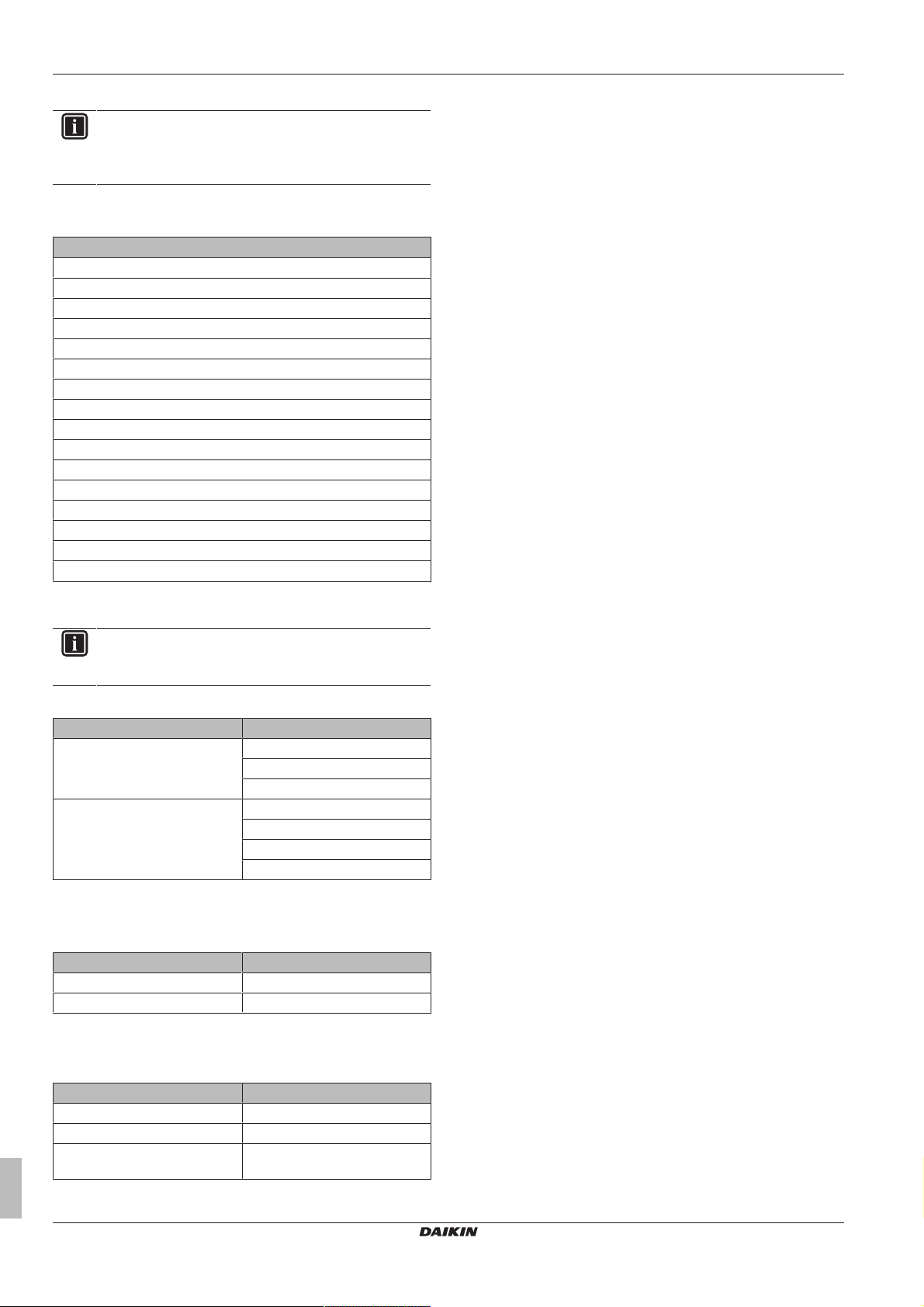
Symbol Explanation
Before installation, read the installation and
operation manual, and the wiring instruction sheet.
Before performing maintenance and service tasks,
read the service manual.
For more information, see the installer and user
reference guide.
1.2 For the user
▪ If you are NOT sure how to operate the unit, contact your installer.
▪ This appliance can be used by children aged from 8 years and
above and persons with reduced physical, sensory or mental
capabilities or lack of experience and knowledge if they have been
given supervision or instruction concerning use of the appliance in
a safe way and understand the hazards involved. Children shall
NOT play with the appliance. Cleaning and user maintenance
shall NOT be made by children without supervision.
WARNING
To prevent electric shocks or fire:
▪ Do NOT rinse the unit.
▪ Do NOT operate the unit with wet hands.
▪ Do NOT place any objects containing water on the unit.
NOTICE
▪ Do NOT place any objects or equipment on top of the
unit.
▪ Do NOT sit, climb or stand on the unit.
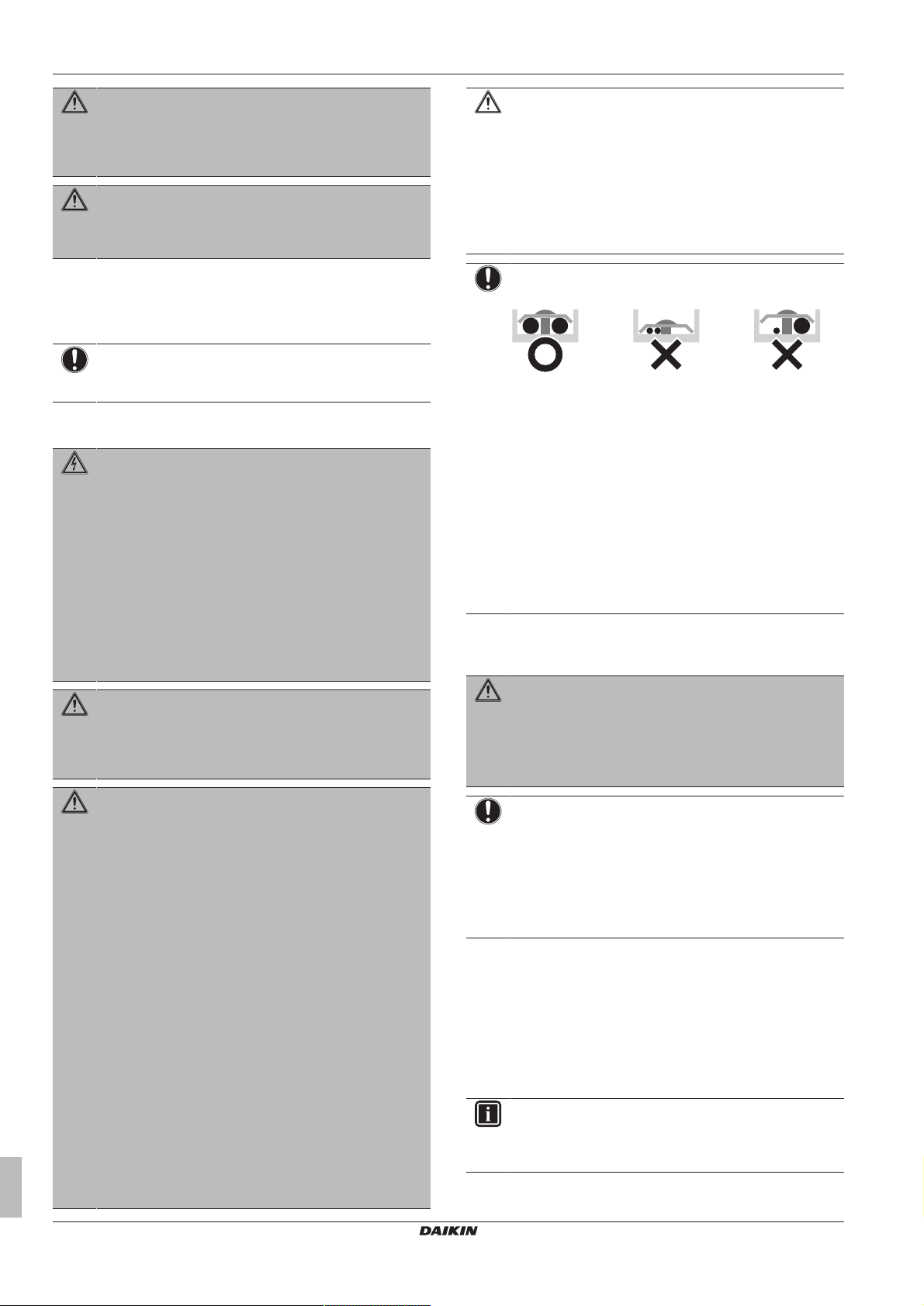
▪ Units are marked with the following symbol:
This means that electrical and electronic products may NOT be
mixed with unsorted household waste. Do NOT try to dismantle
the system yourself: the dismantling of the system, treatment of
the refrigerant, of oil and of other parts must be done by an
authorized installer and must comply with applicable legislation.
Units must be treated at a specialized treatment facility for reuse,
recycling and recovery. By ensuring this product is disposed of
correctly, you will help to prevent potential negative consequences
for the environment and human health. For more information,
contact your installer or local authority.
▪ Batteries are marked with the following symbol:
This means that the batteries may NOT be mixed with unsorted
household waste. If a chemical symbol is printed beneath the
symbol, this chemical symbol means that the battery contains a
heavy metal above a certain concentration.
Possible chemical symbols are: Pb: lead (>0.004%).
Waste batteries must be treated at a specialized treatment facility
for reuse. By ensuring waste batteries are disposed of correctly,
you will help to prevent potential negative consequences for the
environment and human health.
1.3 For the installer
1.3.1 General
If you are NOT sure how to install or operate the unit, contact your
dealer.
NOTICE
Improper installation or attachment of equipment or
accessories could result in electric shock, short-circuit,
leaks, fire or other damage to the equipment. Only use
accessories, optional equipment and spare parts made or
approved by Daikin.
WARNING
Make sure installation, testing and applied materials
comply with applicable legislation (on top of the
instructions described in the Daikin documentation).
CAUTION
Wear adequate personal protective equipment (protective
gloves, safety glasses,…) when installing, maintaining or
servicing the system.
WARNING
Tear apart and throw away plastic packaging bags so that
nobody, especially children, can play with them. Possible
risk: suffocation.
DANGER: RISK OF BURNING
▪ Do NOT touch the refrigerant piping, water piping or
internal parts during and immediately after operation. It
could be too hot or too cold. Give it time to return to
normal temperature. If you must touch it, wear
protective gloves.
▪ Do NOT touch any accidental leaking refrigerant.
WARNING
Provide adequate measures to prevent that the unit can be
used as a shelter by small animals. Small animals that
make contact with electrical parts can cause malfunctions,
smoke or fire.
CAUTION
Do NOT touch the air inlet or aluminium fins of the unit.
NOTICE
▪ Do NOT place any objects or equipment on top of the
unit.
▪ Do NOT sit, climb or stand on the unit.
NOTICE
Works executed on the outdoor unit are best done under
dry weather conditions to avoid water ingress.
In accordance with the applicable legislation, it might be necessary
to provide a logbook with the product containing at least: information
on maintenance, repair work, results of tests, stand-by periods,…
Also, at least, following information MUST be provided at an
accessible place at the product:
▪ Instructions for shutting down the system in case of an emergency
▪ Name and address of fire department, police and hospital
▪ Name, address and day and night telephone numbers for
obtaining service
In Europe, EN378 provides the necessary guidance for this logbook.
Installer and user reference guide
4
VRV IV+ heat pump for high ambient temperatures
RXYTQ8~16U7YF
4P561157-1 – 2018.09
1 General safety precautions
1.3.2 Installation site
▪ Provide sufficient space around the unit for servicing and air
circulation.
▪ Make sure the installation site withstands the unit's weight and
vibration.
▪ Make sure the area is well ventilated. Do NOT block any
ventilation openings.
▪ Make sure the unit is level.
Do NOT install the unit in the following places:
▪ In potentially explosive atmospheres.
▪ In places where there is machinery that emits electromagnetic
waves. Electromagnetic waves may disturb the control system,
and cause malfunction of the equipment.
▪ In places where there is a risk of fire due to the leakage of
flammable gases (example: thinner or gasoline), carbon fibre,
ignitable dust.
▪ In places where corrosive gas (example: sulphurous acid gas) is
produced. Corrosion of copper pipes or soldered parts may cause
the refrigerant to leak.
1.3.3 Refrigerant
If applicable. See the installation manual or installer reference guide
of your application for more information.
NOTICE
Make sure refrigerant piping installation complies with
applicable legislation. In Europe, EN378 is the applicable
standard.
NOTICE
After all the piping has been connected, make sure there is
no gas leak. Use nitrogen to perform a gas leak detection.
NOTICE
▪ To avoid compressor breakdown, do NOT charge more
than the specified amount of refrigerant.
▪ When the refrigerant system is to be opened,
refrigerant MUST be treated according to the applicable
legislation.
WARNING
Make sure there is no oxygen in the system. Refrigerant
may only be charged after performing the leak test and the
vacuum drying.
▪ In case re-charge is required, refer to the nameplate of the unit. It
states the type of refrigerant and necessary amount.
▪ The unit is factory charged with refrigerant and depending on pipe
sizes and pipe lengths some systems require additional charging
of refrigerant.
▪ Only use tools exclusively for the refrigerant type used in the
system, this to ensure pressure resistance and prevent foreign
materials from entering into the system.
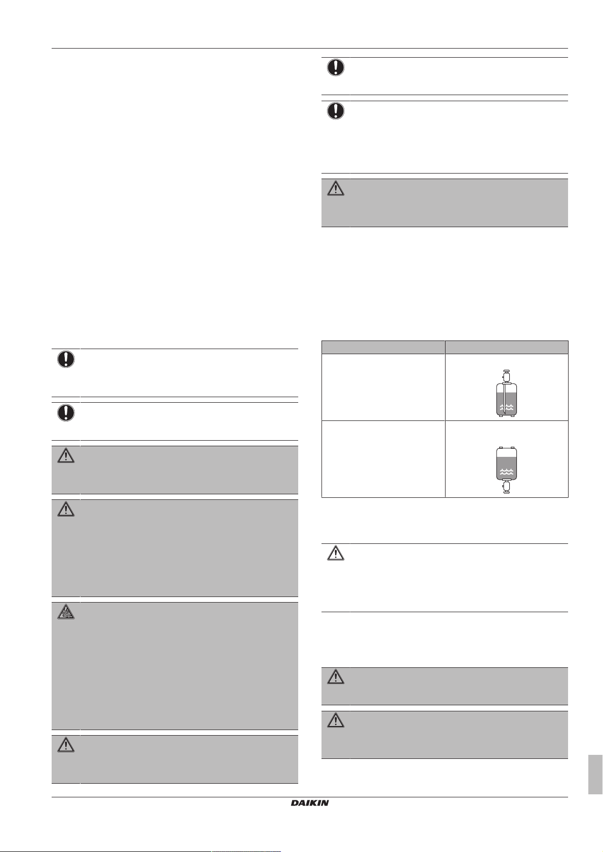
▪ Charge the liquid refrigerant as follows:
If Then
A siphon tube is present
(i.e., the cylinder is marked with
"Liquid filling siphon attached")
Charge with the cylinder upright.
NOTICE
Make sure the field piping and connections are NOT
subjected to stress.
WARNING
During tests, NEVER pressurize the product with a
pressure higher than the maximum allowable pressure (as
indicated on the nameplate of the unit).
WARNING
Take sufficient precautions in case of refrigerant leakage. If
refrigerant gas leaks, ventilate the area immediately.
Possible risks:
▪ Excessive refrigerant concentrations in a closed room
can lead to oxygen deficiency.
▪ Toxic gas may be produced if refrigerant gas comes
into contact with fire.
DANGER: RISK OF EXPLOSION
Pump down – Refrigerant leakage. If you want to pump
down the system, and there is a leak in the refrigerant
circuit:
▪ Do NOT use the unit's automatic pump down function,
with which you can collect all refrigerant from the
system into the outdoor unit. Possible consequence:
Self-combustion and explosion of the compressor
because of air going into the operating compressor.
▪ Use a separate recovery system so that the unit's
compressor does NOT have to operate.
WARNING
ALWAYS recover the refrigerant. Do NOT release them
directly into the environment. Use a vacuum pump to
evacuate the installation.
A siphon tube is NOT present Charge with the cylinder upside
down.
▪ Open refrigerant cylinders slowly.
▪ Charge the refrigerant in liquid form. Adding it in gas form may
prevent normal operation.
CAUTION
When the refrigerant charging procedure is done or when
pausing, close the valve of the refrigerant tank
immediately. If the valve is NOT closed immediately,
remaining pressure might charge additional refrigerant.
Possible consequence: Incorrect refrigerant amount.
1.3.4 Brine
If applicable. See the installation manual or installer reference guide
of your application for more information.
WARNING
The selection of the brine MUST be in accordance with the
applicable legislation.
WARNING
Take sufficient precautions in case of brine leakage. If
brine leaks, ventilate the area immediately and contact
your local dealer.
RXYTQ8~16U7YF
VRV IV+ heat pump for high ambient temperatures
4P561157-1 – 2018.09
Installer and user reference guide
5
2 About the documentation
WARNING
The ambient temperature inside the unit can get much
higher than that of the room, e.g. 70°C. In case of a brine
leak, hot parts inside the unit can create a hazardous
situation.
WARNING
The use and installation of the application MUST comply
with the safety and environmental precautions specified in
the applicable legislation.
1.3.5 Water
If applicable. See the installation manual or installer reference guide
of your application for more information.
NOTICE
Make sure water quality complies with EU directive
98/83EC.
1.3.6 Electrical
DANGER: RISK OF ELECTROCUTION
▪ Turn OFF all power supply before removing the
switch box cover, connecting electrical wiring or
touching electrical parts.
▪ Disconnect the power supply for more than 1 minute,
and measure the voltage at the terminals of main circuit
capacitors or electrical components before servicing.
The voltage MUST be less than 50 V DC before you
can touch electrical components. For the location of the
terminals, see the wiring diagram.
▪ Do NOT touch electrical components with wet hands.
▪ Do NOT leave the unit unattended when the service
cover is removed.
WARNING
If NOT factory installed, a main switch or other means for
disconnection, having a contact separation in all poles
providing full disconnection under overvoltage category III
condition, MUST be installed in the fixed wiring.
WARNING
▪ ONLY use copper wires.
▪ Make sure the field wiring complies with the applicable
legislation.
▪ All field wiring MUST be performed in accordance with
the wiring diagram supplied with the product.
▪ NEVER squeeze bundled cables and make sure they
do NOT come in contact with the piping and sharp
edges. Make sure no external pressure is applied to the
terminal connections.
▪ Make sure to install earth wiring. Do NOT earth the unit
to a utility pipe, surge absorber, or telephone earth.
Incomplete earth may cause electrical shock.
▪ Make sure to use a dedicated power circuit. NEVER
use a power supply shared by another appliance.
▪ Make sure to install the required fuses or circuit
breakers.
▪ Make sure to install an earth leakage protector. Failure
to do so may cause electric shock or fire.
▪ When installing the earth leakage protector, make sure
it is compatible with the inverter (resistant to high
frequency electric noise) to avoid unnecessary opening
of the earth leakage protector.
CAUTION
When connecting the power supply, the earth connection
must be made before the current-carrying connections are
established. When disconnecting the power supply, the
current-carrying connections must be separated before the
earth connection is. The length of the conductors between
the power supply stress relief and the terminal block itself
must be as such that the current-carrying wires are
tautened before the earth wire is in case the power supply
is pulled loose from the stress relief.
NOTICE
Precautions when laying power wiring:
▪ Do NOT connect wiring of different thicknesses to the
power terminal block (slack in the power wiring may
cause abnormal heat).
▪ When connecting wiring which is the same thickness,
do as shown in the figure above.
▪ For wiring, use the designated power wire and connect
firmly, then secure to prevent outside pressure being
exerted on the terminal board.
▪ Use an appropriate screwdriver for tightening the
terminal screws. A screwdriver with a small head will
damage the head and make proper tightening
impossible.
▪ Over-tightening the terminal screws may break them.
Install power cables at least 1metre away from televisions or radios
to prevent interference. Depending on the radio waves, a distance of
1metre may not be sufficient.
WARNING
▪ After finishing the electrical work, confirm that each
electrical component and terminal inside the electrical
components box is connected securely.
▪ Make sure all covers are closed before starting up the
unit.
NOTICE
Only applicable if the power supply is three‑phase, and the
compressor has an ON/OFF starting method.
If there exists the possibility of reversed phase after a
momentary black out and the power goes on and off while
the product is operating, attach a reversed phase
protection circuit locally. Running the product in reversed
phase can break the compressor and other parts.
2 About the documentation
2.1 About this document
Target audience
Authorised installers + end users
INFORMATION
This appliance is intended to be used by expert or trained
users in shops, in light industry and on farms, or for
commercial use by lay persons.
Installer and user reference guide
6
VRV IV+ heat pump for high ambient temperatures
RXYTQ8~16U7YF
4P561157-1 – 2018.09
3 About the box
d
d
b
b
d
c
a
c
Documentation set
This document is part of a documentation set. The complete set
consists of:
▪ General safety precautions:
▪ Safety instructions that you must read before installing
▪ Format: Paper (in the box of the outdoor unit)
▪ Outdoor unit installation and operation manual:
▪ Installation and operation instructions
▪ Format: Paper (in the box of the outdoor unit)
For the installer
3 About the box
3.1 Overview: About the box
This chapter describes what you have to do after the box with the
outdoor unit is delivered on-site.
It contains information about:
▪ Unpacking and handling the outdoor unit
▪ Removing the accessories from the unit
▪ Removing the transportation stay
Keep the following in mind:
▪ At delivery, the unit MUST be checked for damage. Any damage
MUST be reported immediately to the carrier's claims agent.
▪ Bring the packed unit as close as possible to its final installation
position to prevent damage during transport.
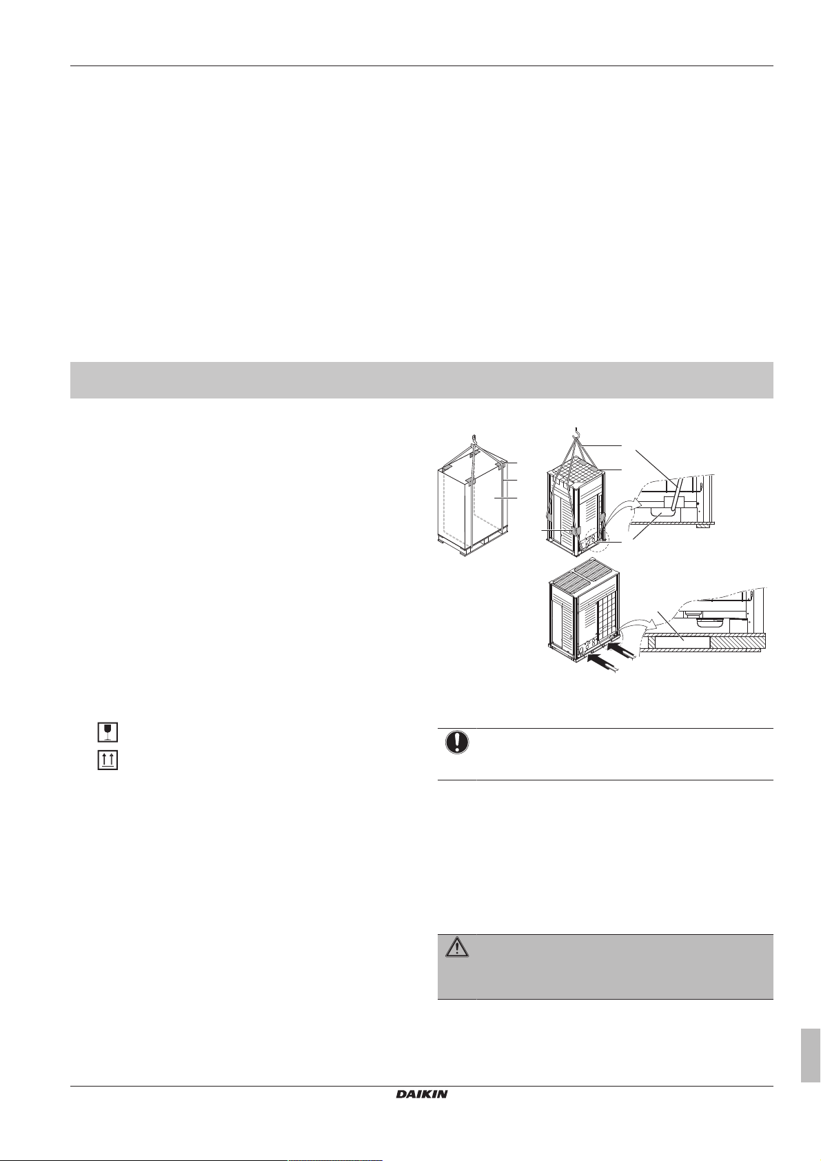
▪ When handling the unit, take into account the following:
Fragile, handle the unit with care.
Keep the unit upright in order to avoid compressor
damage.
▪ Prepare the path along which you want to bring the unit inside in
advance.
▪ Lift the unit preferably with a crane and 2 belts of at least 8m long
as shown in the figure below. Always use protectors to prevent
belt damage and pay attention to the position of the unit's centre
of gravity.
▪ Installer and user reference guide:
▪ Preparation of the installation, reference data,…
▪ Detailed step-by-step instructions and background information
for basic and advanced usage
▪ Format: Digital files on http://www.daikineurope.com/support-
and-manuals/product-information/
Latest revisions of the supplied documentation may be available on
the regional Daikin website or via your dealer.
The original documentation is written in English. All other languages
are translations.
Technical engineering data
▪ A subset of the latest technical data is available on the regional
Daikin website (publicly accessible).
▪ The full set of latest technical data is available on the Daikin
extranet (authentication required).
a Packaging material
b Belt sling
c Opening
d Protector
NOTICE
Use a belt sling of ≤20mm wide that adequately bears the
weight of the unit.
▪ A forklift can only be used for transport as long as the unit remains
on its pallet as shown above.
3.2 To unpack the outdoor unit
Remove the packaging material from the unit:
▪ Take care not to damage the unit when removing the shrink foil
with a cutter.
▪ Remove the 4 bolts fixing the unit to its pallet.
WARNING
Tear apart and throw away plastic packaging bags so that
nobody, especially children, can play with them. Possible
risk: suffocation.
RXYTQ8~16U7YF
VRV IV+ heat pump for high ambient temperatures
4P561157-1 – 2018.09
Installer and user reference guide
7
4 About the units and options
8 HP
10~16 HP
10~16 HP8 HP
a
1×
e
1×
3P328191-1
BE SURE TO FILL OUT THE BLANKS, WHICH ARE NEEDED FOR AFTER-SALE SERVICES.
REQUEST FOR THE INDICATION OF INSTALLATION INFORMATION
1. RECORD OF INDOOR UNIT MODEL AND INSTALLATION SITE
2. RECORD FOR SETTINGS (CONTENTS SEE INSTALLATION MANUAL)
SETTING
40
30
10
2019
9
29
3938
28
8
1817
7
27
3736
26
6
1615
5
25
3534
23 24
4321
INSTALLATION
MODELNAME
No.
12 13 14
504948474645
6059585756
64636261
11
2221
333231
44434241
5554535251
SITE
INSTALLATION
MODELNAME
No.
SITE
INSTALLATION
MODELNAME
No.
SITE
INSTALLATION
MODELNAME
No.
SITE
INSTALLATION
MODELNAME
No.
SITE
INSTALLATION
MODELNAME
No.
SITE
INSTALLATION
MODELNAME
No.
SITE
3. RECORD OF INSTALLATION DATE
6. AFTER EQUIPPING, PLEASE PUT IT ON THE BACK SIDE OF THE FRONT PLATE.
DAY MONTH YEAR
4. MODEL NAME 5. MANUFACTURING NUMBER
VALUE
REMARK DATE SETTING VALUE REMARK DATE
c
1×
b
1×
d
1×
3P328192-1
3. FOR DETAILS CONCERNING PIPING SELECTION AND CALCULATION OR HOW TO OPERATE THE LEAK DETECTION FUNCTION, PLEASE REFER TO THE INSTALLATION MANUAL.
2. RECORD OF ADDITIONAL REFRIGERANT CHARGE AMOUNT AND RESULT OF LEAK CHECK OPERATION
REQUEST FOR THE INDICATION OF ADDITIONAL REFRIGERANT CHARGING AND LEAK DETECTION OPERATION RESULT
BE SURE TO FILL OUT THE BLANKS, WHICH ARE NEEDED FOR AFTER-SALE SERVICES.
1. CALCULATION OF ADDITIONAL REFRIGERANT CHARGING AMOUNT
4. AFTER FILLING IN THIS TABLE, PLEASE PUT IT ON THE SWITCH BOX COVER.
(m) x 0.18(m) x 0.37
kg
OUTDOOR
UNIT
(m) x 0.26
(m) x 0.12 (m) x 0.059
(m) x 0.022
ADDITIONAL CHARGING
AMOUNT
TOTAL LENGTH OF LIQUID
PIPE SIZE O22.2 x 0.37
TOTAL LENGTH OF LIQUID
PIPE SIZE O19.1 x 0.26
TOTAL LENGTH OF LIQUID
PIPE SIZE O15.9 x 0.18
TOTAL LENGTH OF LIQUID
PIPE SIZE O12.7 x 0.12
TOTAL LENGTH OF LIQUID
PIPE SIZE O9.5 x 0.059
TOTAL LENGTH OF LIQUID
PIPE SIZE O6.4 x 0.022
105%< CR < 130%
50%< CR < 105%
50%< CR < 70%
70%< CR < 85%
85%< CR < 105%
105%< CR < 130%
8HP
Total indoor unit
capacity connection
ratio (CR)
10-12HP
14-16HP
18-20HP
2.0
1.5
1.5
1.2
1.5
1
1
0.7
1.0
0.5
0.5
0.3
0.5
0
0
0
1.0
0.5
0.5
0.5
0.5
0
0
0
Total indoor unit capacity
when piping length <30m
Total indoor unit capacity
when piping length >30m
kg
1.3
1.1
0.9
RYYQ18-20
RYYQ14-16
RYYQ8~12
kg
ONLY FOR RYYQ8~20 MODELS
DATE
AMOUNT
CALCULATE THE ADDITIONAL REFRIGERANT CHARGING AMOUNT BASED ON THE FORMULA BELOW BEFORE CHARGING.
SHIPMENT (INDICATED ON THE MACHINE NAMEPLATE) AND THE ADDITIONAL AMOUNT SHOWN AS FOLLOWS :
WHEN RE-CHARGING TOTAL AMOUNT OF REFRIGERANT , CHARGE THE TOTAL OF THE AMOUNT CHARGED AT
RESULT LEAK CHECK
DATE
AMOUNT
RESULT LEAK CHECK
DATE
AMOUNT
RESULT LEAK CHECK
DATE
AMOUNT
RESULT LEAK CHECK
ID Øa
ID Øb
ID Øa
OD Øb
ID Øb
ID Øa
ID Øb
ID Øa
1
3 (12.3 N·m)
2
1
3 (12.3 N·m)
2
a
b
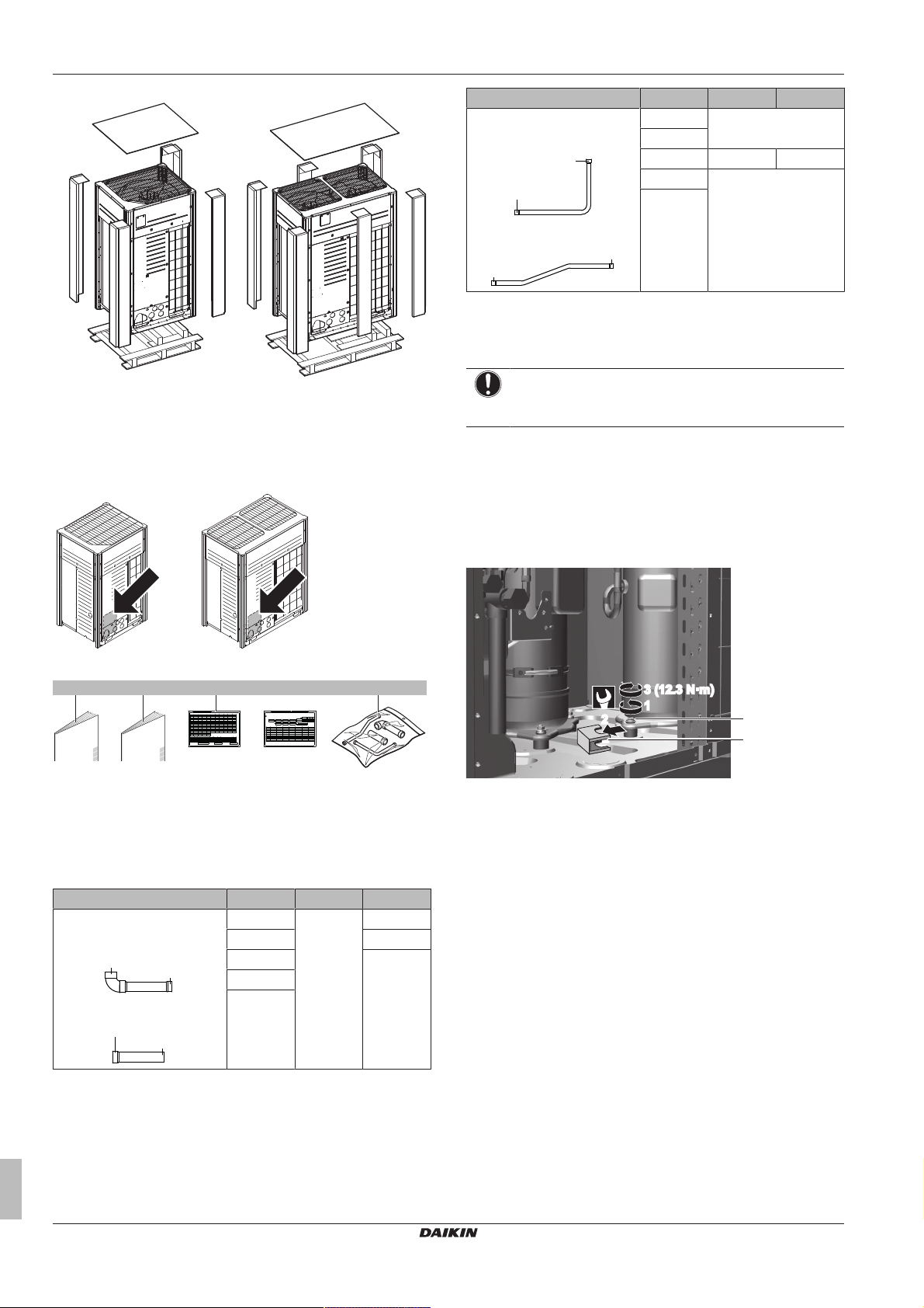
3.3 To remove the accessories from the outdoor unit
Accessory pipes (mm) HP Øa Øb
Liquid pipe
▪ Front connection
8 9.5
10
12 9.5 12.7
14 12.7
16
▪ Bottom connection
3.5 To remove the transportation stay
Only for 14+16 HP
NOTICE
If the unit is operated with the transportation stay attached,
abnormal vibration or noise may be generated.
The transportation stay installed over the compressor leg for
protecting the unit during transport must be removed. Proceed as
shown in the figure and procedure below.
1 Slightly loosen the fixing nut (a).
2 Remove the transportation stay (b) as shown in the figure
below.
3 Tighten the fixing nut (a) again.
Make sure that all accessories are available in the unit.
a General safety precautions
b Installation manual and operation manual
c Additional refrigerant charge label
d Installation information sticker
e Piping accessory bag
3.4 Accessory pipes: Diameters
Accessory pipes (mm) HP Øa Øb
Gas pipe
▪ Front connection
▪ Bottom connection
8 25.4 19.1
10 22.2
12 28.6
14
16
4 About the units and options
4.1 Overview: About the units and options
This chapter contains information about:
▪ Identification of the outdoor unit
▪ Where the outdoor unit fits in the system layout
▪ With which indoor units and options you can combine the outdoor
units
▪ Which outdoor units have to be used as standalone units, and
which outdoor units can be combined
8
Installer and user reference guide
VRV IV+ heat pump for high ambient temperatures
RXYTQ8~16U7YF
4P561157-1 – 2018.09
4 About the units and options
10~16 HP8 HP
e
d
c c
b
f
a
4.2 Identification label: Outdoor unit
Location
Model identification
Example: R X Y T Q 8 U7 YF [*]
Code Explanation
R Outdoor air cooled
X X=Heat pump (no continuous heating)
Y Y=Pair module only
T High ambient (tropical) standard grade
Q Refrigerant R410A
8 Capacity class
U7 Model series
YF Power supply: 3N~, 380-415V, 50Hz
Power supply: 3N~, 400V, 60Hz
[*] Minor model change indication
4.3 About the outdoor unit
This installation manual concerns the VRV IV, full inverter driven,
heat pump system.
Model line up:
Model Description
RXYTQ8~16 Single non-continuous heating model.
RXYTQ18~48 Multi non-continuous heating model
(consisting of 2 or 3 RXYTQ modules).
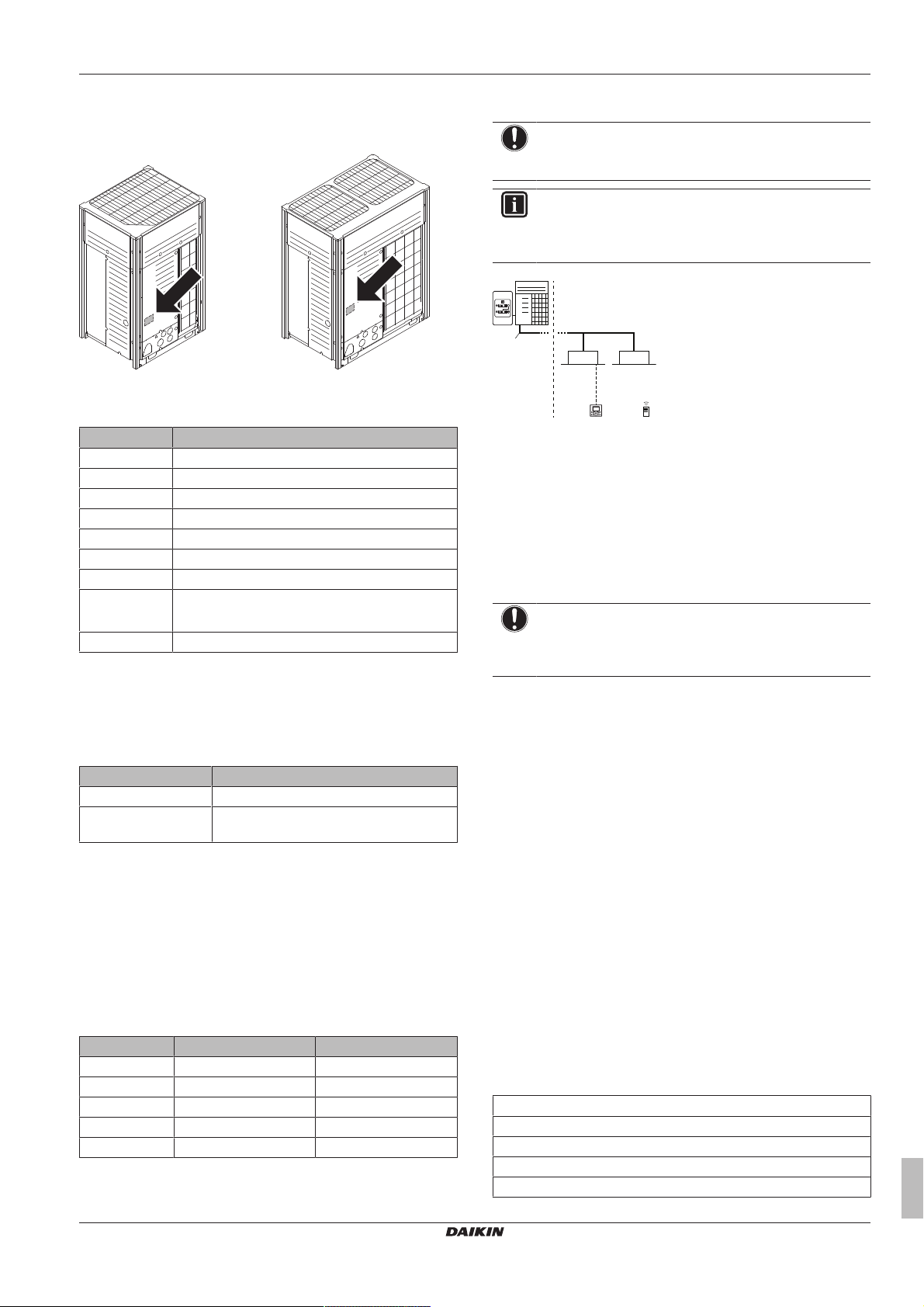
4.4 System layout
NOTICE
Design of the system must not be done at temperatures
below –15°C.
INFORMATION
Not all combinations of indoor units are allowed, for
guidance, see "4.5.2 Possible combinations of indoor
units"on page9.
a VRV IV Heat pump outdoor unit
b Refrigerant piping
c VRV direct expansion (DX) indoor unit
d User interface (dedicated depending on indoor unit type)
e User interface (wireless, dedicated depending on indoor
unit type)
f Cool/Heat changeover remote control switch
4.5 Combining units and options
4.5.1 About combining units and options
NOTICE
To be sure your system setup (outdoor unit+indoor unit(s))
will work, you have to consult the latest technical
engineering data for VRV IV heat pump.
The VRV IV heat pump system can be combined with several types
of indoor units and is intended for R410A use only.
For an overview which units are available you can consult the
product catalogue for VRV IV.
An overview is given indicating the allowed combinations of indoor
units and outdoor units. Not all combinations are allowed. They are
subject to rules (combination between outdoor-indoor, single outdoor
unit use, multiple outdoor unit use, combinations between indoor
units, etc.) mentioned in the technical engineering data.
These units are intended for outdoor installation and aimed for heat
pump air to air applications.
These units have (in single use) heating capacities ranging from 25
to 50kW and cooling capacities rating from 22.4 to 45 kW. In multi
combination the heating capacity can go up till 150 kW and in
cooling till 135kW.
The outdoor unit is designed to work in heating mode at ambient
temperatures from –20°CWB to 15.5°CWB and in cooling mode at
ambient temperatures from –5°CDB to 52°CDB.
Unit weights
Model Total net weight (kg) Total gross weight (kg)
RXYTQ8 198 211
RXYTQ10 234 251
RXYTQ12 234 251
RXYTQ14 283 300
RXYTQ16 283 300
RXYTQ8~16U7YF
VRV IV+ heat pump for high ambient temperatures
4P561157-1 – 2018.09
4.5.2 Possible combinations of indoor units
In general following type of indoor units can be connected to a VRV
IV heat pump system. The list is non-exhaustive and is depending
on both outdoor unit model and indoor unit model combinations.
▪ VRV direct expansion (DX) indoor units (air to air applications).
▪ AHU (air to air applications): EKEXV-kit+EKEQ-box are required,
depending on application.
▪ Aircurtain (air to air applications): CYQ/CAV (Biddle) series,
depending on application.
4.5.3 Possible combinations of outdoor units
Possible standalone outdoor units
RXYTQ8
RXYTQ10
RXYTQ12
RXYTQ14
RXYTQ16
Installer and user reference guide
9
5 Preparation
Possible standard combinations of outdoor units
INFORMATION
U-series units cannot share the same refrigerant circuit
with T-series units. However, electrically, U-series units
and T-series units can be connected via F1/F2.
▪ RXYTQ18~48 consist of 2 or 3 RXYTQ8~16 units.
▪ Only the combinations in the table below are allowed.
Continuous heating
RXYTQ18 = RXYTQ10 + 8
RXYTQ20 = RXYTQ10 + 10
RXYTQ22 = RXYTQ10 + 12
RXYTQ24 = RXYTQ12 + 12
RXYTQ26 = RXYTQ14 + 12
RXYTQ28 = RXYTQ14 + 14
RXYTQ30 = RXYTQ10 + 10 + 10
RXYTQ32 = RXYTQ12 + 10 + 10
RXYTQ34 = RXYTQ12 + 12 + 10
RXYTQ36 = RXYTQ12 + 12 + 12
RXYTQ38 = RXYTQ14 + 12 + 12
RXYTQ40 = RXYTQ14 + 14 + 12
RXYTQ42 = RXYTQ14 + 14 + 14
RXYTQ44 = RXYTQ16 + 16 + 12
RXYTQ46 = RXYTQ16 + 16 + 14
RXYTQ48 = RXYTQ16 + 16 + 16
4.5.4 Possible options for the outdoor unit
External control adaptor (DTA104A61/62)
To instruct specific operation with an external input coming from a
central control the external control adaptor can be used. Instructions
(group or individual) can be instructed for low noise operation and
power consumption limitation operation.
PC configurator cable (EKPCCAB)
You can make several commissioning field settings through a
personal computer interface. For this option EKPCCAB is required
which is a dedicated cable to communicate with the outdoor unit.
The user interface software is available on http://
www.daikineurope.com/support-and-manuals/software-downloads/.
Demand PCB (EKRP1AHTA)
To enable the power saving consumption control by digital inputs
you must install the demand PCB.
For installation instructions, see the installation manual of the
demand PCB and addendum book for optional equipment.
5 Preparation
5.1 Overview: Preparation
This chapter describes what you have to do and know before going
on-site.
It contains information about:
▪ Preparing the installation site
▪ Preparing the refrigerant piping
▪ Preparing the electrical wiring
INFORMATION
Refer to the technical engineering data for the latest option
names.
Refrigerant branching kit
Description Model name
Refnet header KHRQ22M29H
KHRQ22M64H
KHRQ22M75H
Refnet joint KHRQ22M20T
KHRQ22M29T9
KHRQ22M64T
KHRQ22M75T
For the selection of the optimal branching kit, please refer to
"5.3.3To select refrigerant branch kits"on page14.
Outdoor multi connection piping kit
Number of outdoor units Model name
2 BHFQ22P1007
3 BHFQ22P1517
Cool/heat selector
In order to control the cooling or heating operation from a central
location, the following option can be connected:
Description Model name
Cool/heat changeover switch KRC19-26A
Cool/heat changeover PCB BRP2A81
With optional fixing box for the
switch
KJB111A
5.2 Preparing the installation site
5.2.1 Installation site requirements of the outdoor unit
▪ Provide sufficient space around the unit for servicing and air
circulation.
▪ Make sure the installation site withstands the unit's weight and
vibration.
▪ Make sure the area is well ventilated. Do NOT block any
ventilation openings.
▪ Make sure the unit is level.
▪ Select a place where rain can be avoided as much as possible.
▪ Select the location of the unit in such a way that the sound
generated by the unit does not disturb anyone, and the location is
selected according the applicable legislation.
Do NOT install the unit in the following places:
▪ In potentially explosive atmospheres.
▪ In places where there is machinery that emits electromagnetic
waves. Electromagnetic waves may disturb the control system,
and cause malfunction of the equipment.
▪ In places where there is a risk of fire due to the leakage of
flammable gases (example: thinner or gasoline), carbon fibre,
ignitable dust.
▪ In places where corrosive gas (example: sulphurous acid gas) is
produced. Corrosion of copper pipes or soldered parts may cause
the refrigerant to leak.
▪ In places where a mineral oil mist, spray or vapour may be
present in the atmosphere. Plastic parts may deteriorate and fall
off or cause water leakage.
Installer and user reference guide
10
VRV IV+ heat pump for high ambient temperatures
RXYTQ8~16U7YF
4P561157-1 – 2018.09
5 Preparation
b
baa
c
df e
(mm)
≥
1500
≥
1500
≥
1500
≥
1000≥1000
≥
1000≥1000
≥
1000≥1000
e
b
c
a
a
b
c
d
c
d
NOTICE
This is a class A product. In a domestic environment this
product may cause radio interference in which case the
user may be required to take adequate measures.
NOTICE
The equipment described in this manual may cause
electronic noise generated from radio-frequency energy.
The equipment complies to specifications that are
designed to provide reasonable protection against such
interference. However, there is no guarantee that
interference will not occur in a particular installation.
It is therefore recommended to install the equipment and
electric wires keeping proper distances away from stereo
equipment, personal computers, etc.
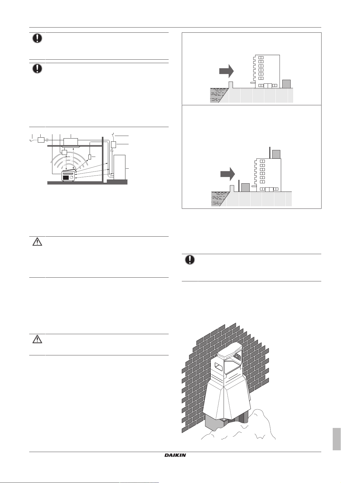
a Personal computer or radio
b Fuse
c Earth leakage protector
d User interface
e Indoor unit
f Outdoor unit
In places with weak reception, keep distances of 3 m or more to
avoid electromagnetic disturbance of other equipment and use
conduit tubes for power and transmission lines.
Install the outdoor unit away from direct sea winds.
Example: Behind the building.
If the outdoor unit is exposed to direct sea winds, install a
windbreaker.
▪ Height of windbreaker≥1.5×height of outdoor unit
▪ Mind the service space requirements when installing the
windbreaker.
a Sea wind
b Building
c Outdoor unit
d Windbreaker
CAUTION
Appliance not accessible to the general public, install it in a
secured area, protected from easy access.
This unit, both indoor and outdoor, is suitable for
installation in a commercial and light industrial
environment.
▪ When installing, take strong winds, typhoons or earthquakes into
account, improper installation may result in the unit turning over.
▪ Take care that in the event of a water leak, water cannot cause
any damage to the installation space and surroundings.
▪ When installing the unit in a small room, take measures in order to
keep the refrigerant concentration from exceeding allowable
safety limits in the event of a refrigerant leak, refer to "About
5.2.2 Additional installation site requirements of the outdoor unit in cold climates
NOTICE
When operating the unit in a low outdoor ambient
temperature, be sure to follow the instructions described
below.
▪ To prevent exposure to wind and snow, install a baffle plate on the
air side of the outdoor unit:
In heavy snowfall areas it is very important to select an installation
site where the snow will NOT affect the unit. If lateral snowfall is
possible, make sure that the heat exchanger coil is NOT affected by
the snow. If necessary, install a snow cover or shed and a pedestal.
safety against refrigerant leaks"on page12.
CAUTION
Excessive refrigerant concentrations in a closed room can
lead to oxygen deficiency.
▪ Be sure that the air inlet of the unit is not positioned towards the
main wind direction. Frontal wind will disturb the operation of the
unit. If necessary, use a screen to block the wind.
▪ Ensure that water cannot cause any damage to the location by
adding water drains to the foundation and prevent water traps in
the construction.
Seaside installation. Make sure the outdoor unit is NOT directly
exposed to sea winds. This is to prevent corrosion caused by high
levels of salt in the air, which might shorten the life of the unit.
RXYTQ8~16U7YF
VRV IV+ heat pump for high ambient temperatures
4P561157-1 – 2018.09
Installer and user reference guide
11
5 Preparation
T
AO
(°C WB)
a b
20
15.5
15
10
5
0
–5
–10
–15
–20
10 15 20 25
27
30
T
AI
(°C DB)
b
a
a
b
INFORMATION
For instructions on how to install the snow cover, contact
your dealer.
NOTICE
When installing the snow cover, do NOT obstruct the air
flow of the unit.
NOTICE
When operating the unit in a low outdoor ambient
temperature with high humidity conditions, make sure to
take precautions to keep the drain holes of the unit free by
using proper equipment.
In heating:
a Warming up operation range
b Operation range
TAI Ambient indoor temperature
TAO Ambient outdoor temperature
a Direction of the refrigerant flow
b Room where refrigerant leak has occurred (outflow of all
the refrigerant from the system)
Pay special attention to places, such as basements etc., where
refrigerant can stay, since refrigerant is heavier than air.
To check the maximum concentration level
Check the maximum concentration level in accordance with steps 1
to 4 below and take whatever action is necessary to comply.
1 Calculate the amount of refrigerant (kg) charged to each system
separately.
Formula A+B=C
A Amount of refrigerant in a single unit system
(amount of refrigerant with which the system
is charged before leaving the factory)
B Additional charging amount (amount of
refrigerant added locally)
C Total amount of refrigerant (kg) in the
system
NOTICE
Where a single refrigerant facility is divided into 2 entirely
independent refrigerant systems, use the amount of
refrigerant with which each separate system is charged.
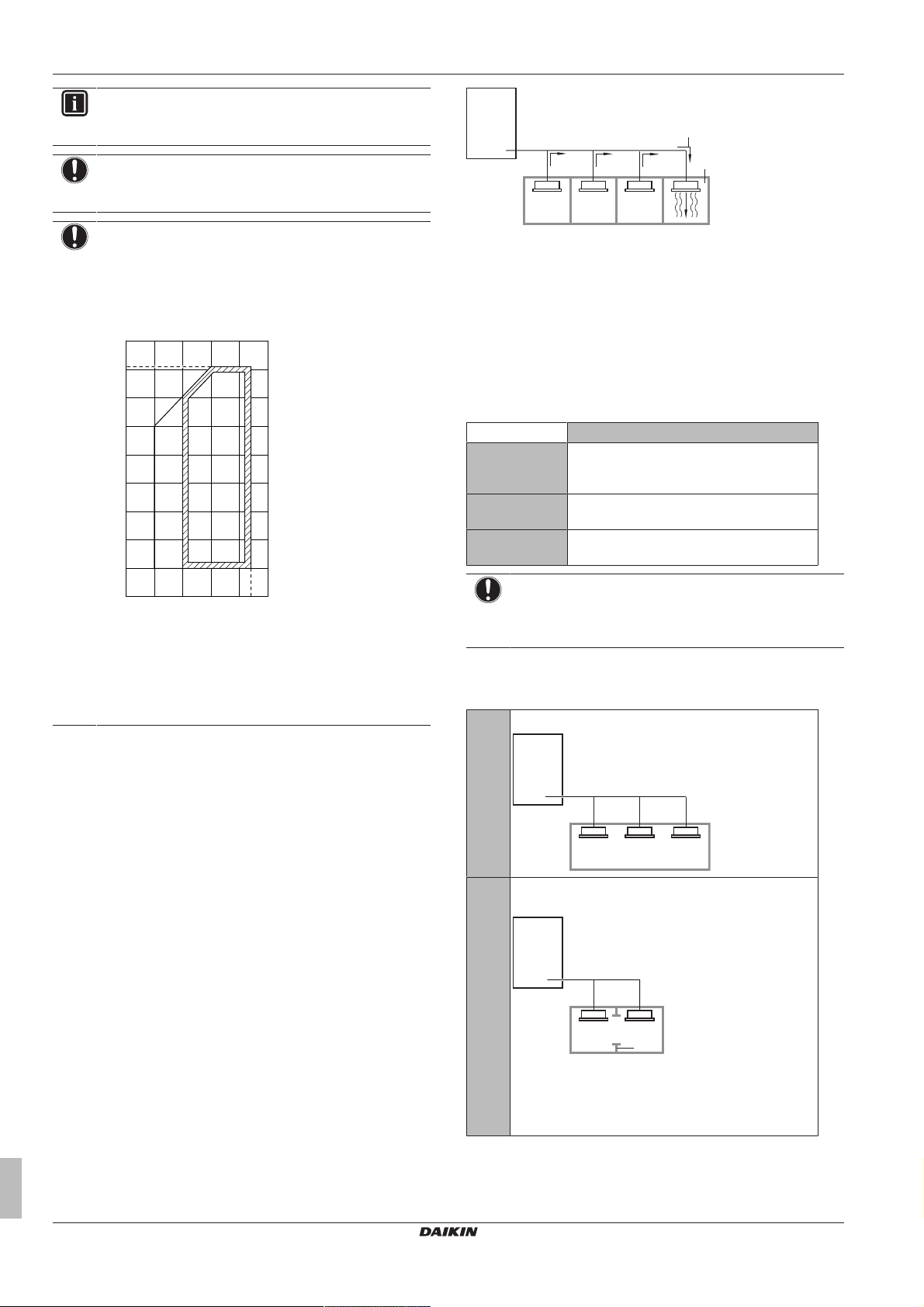
2 Calculate the volume of the room (m3) where the indoor unit is
installed. In a case such as the following, calculate the volume
of (D), (E) as a single room or as the smallest room.
D When there are no smaller room divisions:
5.2.3 Securing safety against refrigerant leaks
About safety against refrigerant leaks
The installer and system specialist shall secure safety against
leakage according to local regulations or standards. The following
standards may be applicable if local regulations are not available.
This system uses R410A as refrigerant. R410A itself is an entirely
safe non-toxic, non-combustible refrigerant. Nevertheless care must
be taken to ensure that the system is installed in a room which is
sufficiently large. This assures that the maximum concentration level
of refrigerant gas is not exceeded, in the unlikely event of major leak
in the system and this in accordance to the local applicable
regulations and standards.
About the maximum concentration level
The maximum charge of refrigerant and the calculation of the
maximum concentration of refrigerant is directly related to the
humanly occupied space in to which it could leak.
The unit of measurement of the concentration is kg/m3 (the weight in
kg of the refrigerant gas in 1m3 volume of the occupied space).
Compliance to the local applicable regulations and standards for the
maximum allowable concentration level is required.
According to the appropriate European Standard, the maximum
allowed concentration level of refrigerant to a humanly space for
R410A is limited to 0.44kg/m3.
Installer and user reference guide
12
E When there is a room division that has an opening
sufficiently large to permit free air flow.
a Opening between the rooms. In case there is a door
the openings above and below the door each must be
equivalent in size to 0.15% or more of the floor area.
b Room division
3 Calculate the refrigerant density using the results of the
calculations in steps 1 and 2 above. If the result of the above
calculation exceeds the maximum concentration level, a
ventilation opening to the adjacent room shall be made.
RXYTQ8~16U7YF
VRV IV+ heat pump for high ambient temperatures
4P561157-1 – 2018.09
5 Preparation
A
B B B
C
D
E
x
y
b
a
1 2 3 4
b
a
e
b
c
d
Formula F/G≤H
F Total volume of refrigerant in the refrigerant
system
G Size (m3) of smallest room in which there is
an indoor unit installed
H Maximum concentration level (kg/m3)
4 Calculate the refrigerant density taking the volume of the room
where the indoor unit is installed and the adjacent room. Install
ventilation openings in the door of adjacent rooms until the
refrigerant density is smaller than the maximum concentration
level.
5.3 Preparing refrigerant piping
5.3.1 Refrigerant piping requirements
NOTICE
The refrigerant R410A requires strict cautions for keeping
the system clean, dry and tight.
▪ Clean and dry: foreign materials (including mineral oils
or moisture) should be prevented from getting mixed
into the system.
▪ Tight: R410A does not contain any chlorine, does not
destroy the ozone layer, and does not reduce earth's
protection against harmful ultraviolet radiation. R410A
can contribute to the greenhouse effect if it is released.
Therefore pay special attention to check the tightness
of the installation.
NOTICE
The piping and other pressure-containing parts shall be
suitable for refrigerant. Use phosphoric acid deoxidised
seamless copper for refrigerant.
▪ Only use phosphoric acid deoxidised seamless copper.
▪ Foreign materials inside pipes (including oils for fabrication) must
be ≤30mg/10m.
▪ Temper grade: use piping with temper grade in function of the
pipe diameter as listed in table below.
Pipe Ø Temper grade of piping material
≤15.9mm O (annealed)
≥19.1mm 1/2H (half hard)
▪ All piping lengths and distances have been taken into
consideration (see "5.3.4About the piping length"on page14).
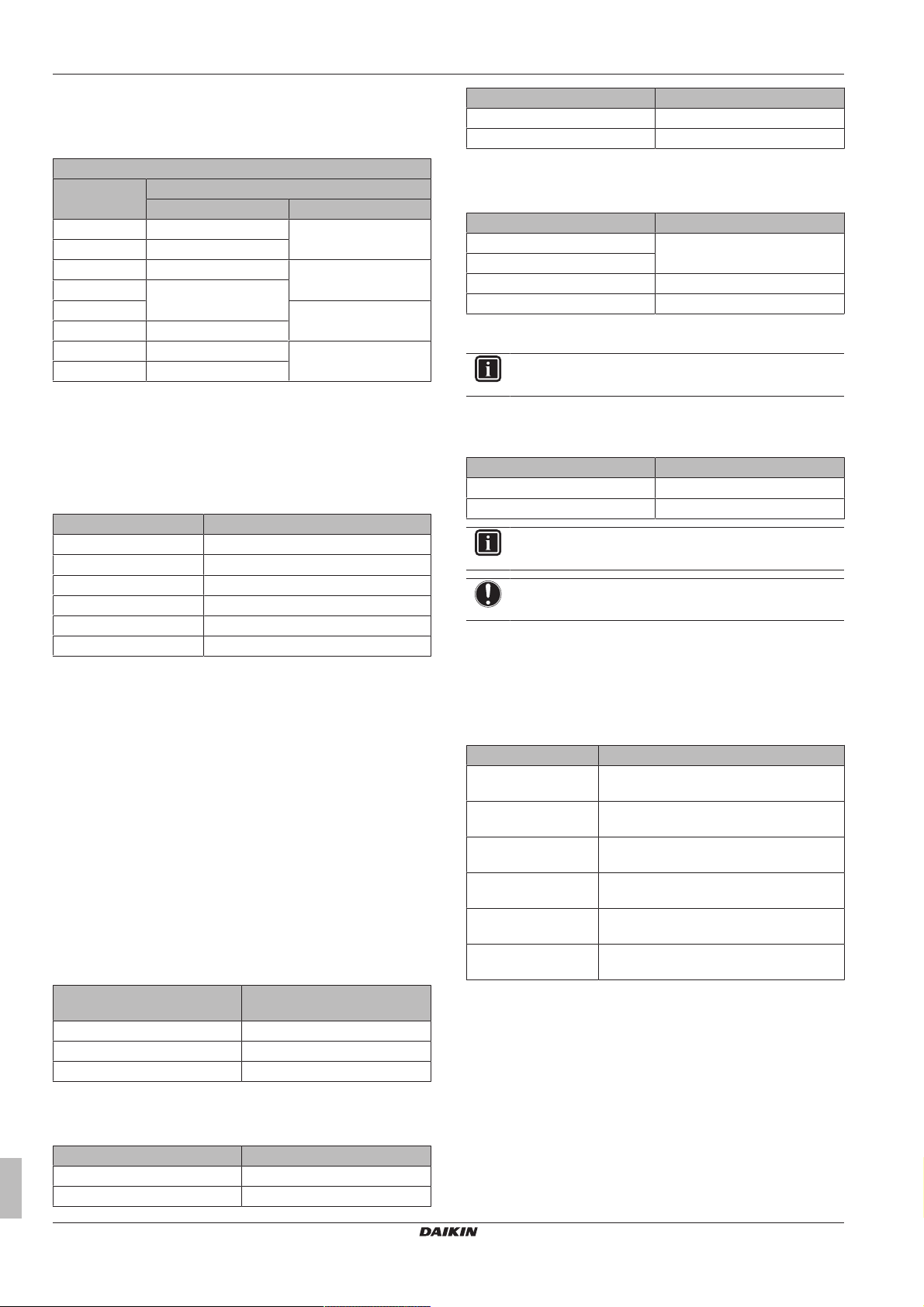
5.3.2 To select the piping size
Determine the proper size using the following tables and reference
figure (only for indication).
a,b Indoor branch kit
x,y Outdoor multi connection kit
A, B, C: Piping between outdoor unit and (first) refrigerant branch kit
Choose from the following table in accordance with the outdoor unit
total capacity type, connected downstream.
Outdoor unit
capacity type (HP)
8 19.1 9.5
10 22.2 9.5
12~16 28.6 12.7
18~22 28.6 15.9
24 34.9 15.9
26~34 34.9 19.1
36~48 41.3 19.1
Piping outer diameter size (mm)
Gas pipe Liquid pipe
D: Piping between refrigerant branch kits
Choose from the following table in accordance with the indoor unit
total capacity type, connected downstream. Do not let the
connection piping exceed the refrigerant piping size chosen by the
general system model name.
Indoor unit capacity
index
<150 15.9 9.5
150≤x<200 19.1
200≤x<290 22.2
290≤x<420 28.6 12.7
420≤x<640 15.9
640≤x<920 34.9 19.1
≥920 41.3
Example:
▪ Downstream capacity for E=capacity index of unit 1
▪ Downstream capacity for D=capacity index of unit 1+capacity
index of unit 2
Piping outer diameter size (mm)
Gas pipe Liquid pipe
E: Piping between refrigerant branch kit and indoor unit
Pipe size for direct connection to indoor unit must be the same as
the connection size of the indoor unit (in case indoor unit is VRVDX
indoor).
Indoor unit capacity
index
15~50 12.7 6.4
63~140 15.9 9.5
200 19.1
250 22.2
Piping outer diameter size (mm)
Gas pipe Liquid pipe
RXYTQ8~16U7YF
VRV IV+ heat pump for high ambient temperatures
4P561157-1 – 2018.09
1,2,3,4 VRVDX indoor unit
▪ When the equivalent pipe length between outdoor and indoor
units is 90m or more, the size of the main pipes (both gas side
and liquid side) must be increased. Depending on the length of the
piping, the capacity may drop, but even in such a case the size of
the main pipes has to be increased. More specifications can be
found in the technical engineering data book.
Installer and user reference guide
13
5 Preparation
a Outdoor unit
b Main pipes
c Increase if the equivalent piping length is ≥90m
d First refrigerant branch kit
e Indoor unit
Size up
HP class Piping outer diameter size (mm)
Gas pipe Liquid pipe
8 19.1 → 22.2 9.5 → 12.7
10 22.2 → 25.4
12+14 28.6
16 28.6 → 31.8
(a)
(b)
(a)
12.7 → 15.9
18~22 15.9 → 19.1
24 34.9
26~34 34.9 → 38.1
36~48 41.3
(a) If the size-up size is NOT available, you must use the
standard size. Sizes bigger than the size-up size are NOT
allowed. But even if you use the standard size, the
equivalent piping length is allowed to be more than 90m.
(b) Pipe size-up is NOT allowed.
(b)
(a)
(b)
19.1 → 22.2
▪ The pipe thickness of the refrigerant piping shall comply with the
applicable legislation. The minimal pipe thickness for R410A
piping must be in accordance with the table below.
Pipe Ø (mm) Minimal thickness t (mm)
6.4/9.5/12.7 0.80
15.9 0.99
19.1/22.2 0.80
28.6 0.99
34.9 1.21
41.3 1.43
▪ In case the required pipe sizes (inch sizes) are not available, it is
also allowed to use other diameters (mm sizes), taken the
following into account:
▪ Select the pipe size nearest to the required size.
▪ Use the suitable adapters for the change-over from inch to mm
pipes (field supply).
▪ The additional refrigerant calculation has to be adjusted as
mentioned in "6.7.3 To determine the additional refrigerant
amount"on page24.
5.3.3 To select refrigerant branch kits
Refrigerant refnets
For piping example, refer to "5.3.2 To select the piping size" on
page13.
▪ When using refnet joints at the first branch counted from the
outdoor unit side, choose from the following table in accordance
with the capacity of the outdoor unit (example: refnet joint a).
Outdoor unit capacity type
(HP)
8+10 KHRQ22M29T9
12~22 KHRQ22M64T
24~48 KHRQ22M75T
▪ For refnet joints other than the first branch (example refnet joint b),
select the proper branch kit model based on the total capacity
index of all indoor units connected after the refrigerant branch.
2 pipes
Indoor unit capacity index 2 pipes
290≤x<640 KHRQ22M64T
≥640 KHRQ22M75T
▪ Concerning refnet headers, choose from the following table in
accordance with the total capacity of all the indoor units connected
below the refnet header.
Indoor unit capacity index 2 pipes
<200 KHRQ22M29H
200≤x<290
290≤x<640 KHRQ22M64H
(a)
≥640 KHRQ22M75H
(a) If the pipe size above the refnet header is Ø34.9 or more,
KHRQ22M75H is required.
INFORMATION
Maximum 8 branches can be connected to a header.
▪ How to choose an outdoor multi connection piping kit. Choose
from the following table in accordance with the number of outdoor
units.
Number of outdoor units Branch kit name
2 BHFQ22P1007
3 BHFQ22P1517
INFORMATION
Reducers or T-joints are field supplied.
NOTICE
Refrigerant branch kits can only be used with R410A.
5.3.4 About the piping length
Make sure to perform the piping installation within the range of the
maximum allowable pipe length, allowable level difference and
allowable length after branching as indicated below.
Definitions
Term Definition
Actual piping length Pipe length between outdoor
(a)
and indoor
units.
Equivalent piping
(b)
length
Pipe length between outdoor
units.
Total piping length Total piping length from the outdoor
(a)
and indoor
(a)
to all
indoor units.
H1 Difference in height between outdoor and
indoor units.
H2 Difference in height between indoor and
indoor units.
H3 Difference in height between outdoor and
outdoor units.
(a) If the system capacity is >16HP, re-read "the first outdoor
branch as seen from the indoor unit".
(b) Assume equivalent piping length of refnet joint=0.5m and
refnet header=1m (for calculation purposes of equivalent
piping length, not for refrigerant charge calculations).
5.3.5 Piping length: VRV DX only
For system only containing VRVDX indoor units:
Indoor unit capacity index 2 pipes
<200 KHRQ22M20T
200≤x<290 KHRQ22M29T9
Installer and user reference guide
14
VRV IV+ heat pump for high ambient temperatures
RXYTQ8~16U7YF
4P561157-1 – 2018.09
5 Preparation
a
A
h i j k l m n
B C D E F G
p
b c d e f
1 2 3 4 5 6 7
8
g
H1
H2
a
b
c d e f
i
k
j
g h
A B
1 2 3 4 5 6
7 8
H1
H2
a
c
b d e fig h
1 2 3 4 5 6 7
8
H1
H2
a
A
h i j k l m n
B C D E F G
p
b c d e f
1 2 3 4 5 6 7
8
g
t
u
r
s
H1
H2
a
j k
b
1 2 3 4 5 6
7 8
c d e f g h
t
u
r
s
BA
H1
H3
H2
a
b
1 2 3 4 5 6 7
8
c d e f g h i
t
u
r
s
H1
H3
H2
r s
u
t
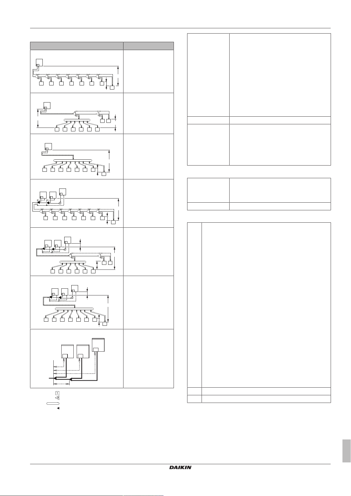
System setup
Example Description
Example 1.1
Single outdoor
Branch with refnet joint
Example 1.2
Single outdoor
Branch with refnet joint
and refnet header
Example 1.3
Single outdoor
Branch with refnet
header
Example 2.1
Multi outdoor
Branch with refnet joint
Actual piping
length
165m/135m
Example 1.1
▪ unit8: a+b+c+d+e+f+g+p≤165m
Example 1.2
▪ unit6: a+b+h≤165m
▪ unit8: a+i+k≤165m
Example 1.3
▪ unit8: a+i≤165m
Example 2.1
▪ unit8: a+b+c+d+e+f+g+p≤135m
Equivalent length 190m/160m
Total piping
length
1000m/500m
Example 1.1
▪ a+b+c+d+e+f+g+h+i+j+k+l+m+n+p≤1000m
Example 2.1
▪ a+b+c+d+e+f+g+h+i+j+k+l+m+n+p≤500m
▪ Between outdoor branch and outdoor unit (only in case >16HP)
Actual piping
length
10m
Example 3
▪ r, s, t≤10m; u≤5m
Equivalent length 13m
Example 2.2
Multi outdoor
Branch with refnet joint
and refnet header
Example 2.3
Multi outdoor
Branch with refnet
header
Example 3
With standard multi
layout
Indoor unit
Refnet joint
Refnet header
Outdoor multi connection piping kit
Maximum allowable length
▪ Between outdoor and indoor units (single installation/multi
combinations)
Maximum allowable height difference
H1 ≤50m (40m) (if outdoor is located below indoor units)
Conditional extension up till 90m is possible without
additional option kit:
▪ In case the outdoor location is higher than indoor:
extension is possible up till 90 m and following
2conditions must be fulfilled:
▪ Liquid piping size up (see table "Size up" in "E: Piping
between refrigerant branch kit and indoor unit" on
page13).
▪ Dedicated setting on outdoor unit is required (see [2‑49]
in "7.2.8Mode 2: Field settings"on page35).
▪ In case the outdoor location is lower than indoor:
extension is possible up till 90 m and following
6conditions must be fulfilled:
▪ 40~60m: minimum connection ratio connected: 80%.
▪ 60~65m: minimum connection ratio connected: 90%.
▪ 65~80m: minimum connection ratio connected: 100%.
▪ 80~90m: minimum connection ratio connected: 110%.
▪ Liquid piping size up (see table "Size up" in "E: Piping
between refrigerant branch kit and indoor unit" on
page13).
▪ Dedicated setting on outdoor unit is required (see [2‑35]
in "7.2.8Mode 2: Field settings"on page35).
H2 ≤30m
H3 ≤5m
Maximum allowable length after branch
The pipe length from the first refrigerant branch kit to the indoor unit
≤40 m.
Example 1.1: unit 8: b+c+d+e+f+g+p≤40m
Example 1.2: unit 6: b+h≤40m, unit 8: i+k≤40m
Example 1.3: unit 8: i≤40m
RXYTQ8~16U7YF
VRV IV+ heat pump for high ambient temperatures
4P561157-1 – 2018.09
Installer and user reference guide
15
5 Preparation
a
A
h i j k l m n
B C D E F G
p
b c d e f
1 2 3 4 5 6 7
8
g
H1
H2
1
2
3
a
b
b
a
b
a
a
b
a
b
b
a
a
a
b b b
a
b b b
a
b
a
b
a
b
a
a
a
≥200 mm
a
b
≤2 m
a
≤2 m ≤2 m
≥200 mm
≥200 mm
b
>2 m >2 m
However, extension is possible if all below conditions are met. In this
case limitation can be extended up to 90m.
1 Outdoor units
2 Refnet joints (A~G)
3 Indoor unit (1~8)
Conditions:
a The piping length between all indoor units to the nearest branch
kit is ≤40m.
Example: h, i, j … p≤40m
b It is necessary to increase the pipe size of the gas and liquid
piping if the pipe length between the first branch kit and the
farthest indoor unit is over 40m.
If the increased pipe size is larger than the pipe size of the main
pipe, then the pipe size of the main pipe has to be increased as
well.
Increase the pipe size as follows:
9.5 → 12.7; 12.7 → 15.9; 15.9 → 19.1; 19.1 → 22.2; 22.2 →
25.4
(a)
; 28.6 → 31.8
(a)
; 34.9 → 38.1
(a)
(a) If the size-up size is NOT available, you must use the
standard size. Sizes bigger than the size-up size are NOT
allowed. But even if you use the standard size, you can
increase the maximum allowable length after the first branch if
all other conditions are met.
Example: unit8: b+c+d+e+f+g+p≤90m and b+c+d+e+f
+g>40m; increase the pipe size of b, c, d, e, f, g.
c When the piping size is increased (stepb), the piping length
has to be counted as double (except for the main pipe and the
pipes that are not increased in pipe size).
The total piping length has to be within limitations (see table
above).
Example: a+b×2+c×2+d×2+e×2+f×2+g×2+h+i+j+k+l+m+n
+p≤1000m (500m).
d The piping length difference between the nearest indoor unit
(from first branch) to the outdoor unit and the farthest indoor
unit to the outdoor unit is ≤40m.
Example: The farthest indoor unit 8. The nearest indoor unit 1
→ (a+b+c+d+e+f+g+p)–(a+h)≤40m.
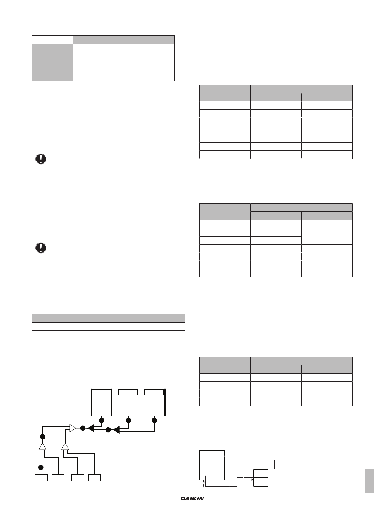
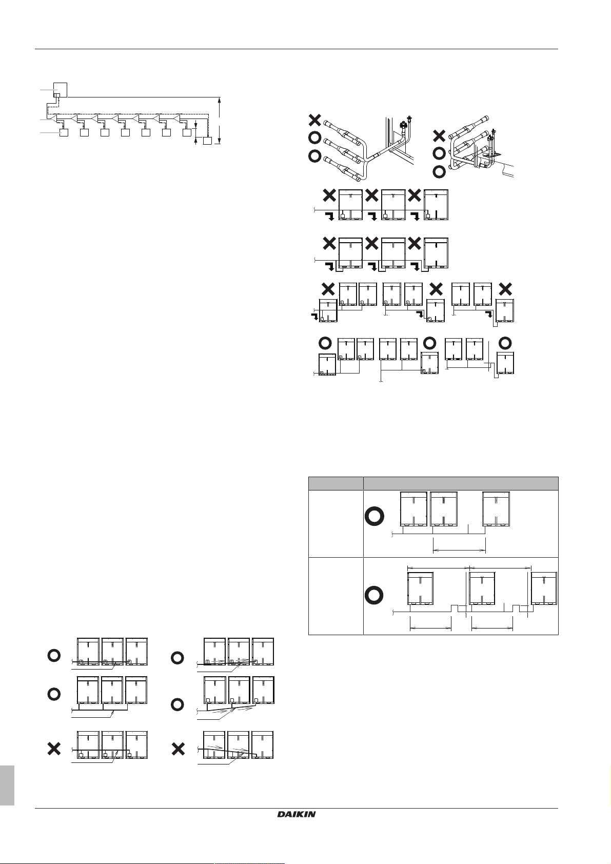
X Not allowed (oil remains in piping)
O Allowed
▪ To avoid the risk of oil retention to the outmost outdoor unit,
always connect the stop valve and the piping between outdoor
units as shown in the 4 correct possibilities of the figure below.
a To indoor unit
b Oil collects to the outmost outdoor unit when the system
stops
X Not allowed
O Allowed
▪ If the piping length between the outdoor units exceeds 2m, create
a rise of 200mm or more in the gas line within a length of 2 m
from the kit.
If Then
≤2m
>2m
5.3.6 Multiple outdoor units: Possible layouts
▪ The piping between the outdoor units must be routed level or
slightly upward to avoid the risk of oil retention into the piping.
Pattern 1
a To indoor unit
b Piping between outdoor units
Installer and user reference guide
16
Pattern 2
a To indoor unit
b Piping between outdoor units
VRV IV+ heat pump for high ambient temperatures
RXYTQ8~16U7YF
4P561157-1 – 2018.09
6 Installation
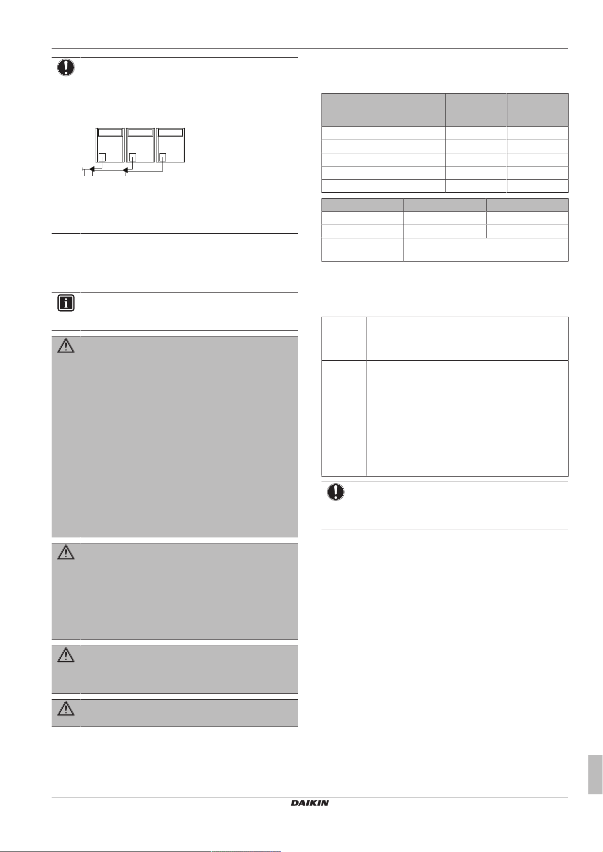
A B C
a b c
NOTICE
There are restrictions on the refrigerant pipe connection
order between outdoor units during installation in case of a
multiple outdoor unit system. Install according to following
restrictions. The capacities of outdoor units A, B and C
must fulfill the following restriction conditions: A≥B≥C.
a To indoor units
b Outdoor unit multi connecting piping kit (first branch)
c Outdoor unit multi connecting piping kit (second branch)
5.4 Preparing electrical wiring
5.4.1 About preparing electrical wiring
INFORMATION
Also read the precautions and requirements in the
"General safety precautions" chapter.
WARNING
▪ If the power supply has a missing or wrong N-phase,
equipment might break down.
▪ Establish proper earthing. Do NOT earth the unit to a
utility pipe, surge absorber, or telephone earth.
Incomplete earthing may cause electrical shock.
▪ Install the required fuses or circuit breakers.
▪ Secure the electrical wiring with cable ties so that the
cables do NOT come in contact with sharp edges or
piping, particularly on the high-pressure side.
▪ Do NOT use taped wires, stranded conductor wires,
extension cords, or connections from a star system.
They can cause overheating, electrical shock or fire.
▪ Do NOT install a phase advancing capacitor, because
this unit is equipped with an inverter. A phase
advancing capacitor will reduce performance and may
cause accidents.
Selection and sizing of the wiring should be done in accordance with
the applicable legislation based on the information mentioned in the
table below.
Model Minimum
RXYTQ8 16.1A 20A
RXYTQ10 22.0A 25A
RXYTQ12 24.0A 32A
RXYTQ14 27.0A 32A
RXYTQ16 31.0A 40A
What? Case1 Case2
Phase and frequency 3N~50Hz 3N~60Hz
Voltage 380-415V 400V
Transmission line
(a)
section
(a) Maximum length is 1000 m. If the total transmission wiring
exceeds these limits, it may result in communication error.
For multi combinations
Calculate the recommended fuse capacity.
Formula Calculate, by adding the minimum circuit amps of each
Example Combining the RXYTQ30 by using the RXYTQ8,
used unit (according to the table above), multiply the
result by 1.1 and select the next higher recommended
fuse capacity.
RXYTQ10, and RXYTQ12.
▪ Minimum circuit ampacity of the RXYTQ8=16.1A
▪ Minimum circuit ampacity of the RXYTQ10=22.0A
▪ Minimum circuit ampacity of the RXYTQ12=24.0A
Accordingly, the minimum circuit ampacity of the
RXYTQ30=16.1+22.0+24.0=62.1A
Multiply the above result by 1.1 ⇒ (62.1A×1.1)=68.3A,
so the recommended fuse capacity would be 80A.
NOTICE
When using residual current operated circuit breakers, be
sure to use a high-speed type 300 mA rated residual
operating current.
circuit
ampacity
0.75~1.25mm
Recommended
fuses
2
WARNING
▪ All wiring MUST be performed by an authorised
electrician and MUST comply with the applicable
legislation.
▪ Make electrical connections to the fixed wiring.
▪ All components procured on-site and all electrical
construction MUST comply with the applicable
legislation.
WARNING
The backup heater MUST have a dedicated power supply
and MUST be protected by the safety devices required by
the applicable legislation.
WARNING
ALWAYS use multicore cable for power supply cables.
5.4.2 Safety device requirements
The power supply must be protected with the required safety
devices, i.e. a main switch, a slow blow fuse on each phase and an
earth leakage protector in accordance with the applicable legislation.
RXYTQ8~16U7YF
VRV IV+ heat pump for high ambient temperatures
4P561157-1 – 2018.09
6 Installation
6.1 Overview: Installation
This chapter describes what you have to do and know on-site to
install the system.
Typical workflow
Installation typically consists of the following stages:
1 Opening the units
2 Mounting the outdoor unit
3 Connecting the refrigerant piping
4 Checking the refrigerant piping
5 Insulating the refrigerant piping
6 Charging refrigerant
7 Connecting the electrical wiring
Installer and user reference guide
17
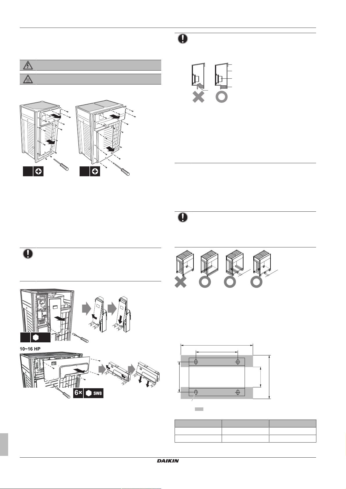
6 Installation
14×14×
8 HP 10~16 HP
8 HP
2×
SW8
10~16 HP
6×
SW8
a
b
c
d
e
≥100 mm
≥100 mm
*
729
≤613
≥929
≥AB
AA
a
(mm)
6.2 Opening the units
6.2.1 To open the outdoor unit
DANGER: RISK OF ELECTROCUTION
DANGER: RISK OF BURNING
To gain access to the unit, front plates need to be opened as follows:
Once the front plates open, the electrical component box can be
accessed. See "6.2.2 To open the electrical component box of the
outdoor unit"on page18.
For service purposes, the pushbuttons on the main PCB need to be
accessed. To access these pushbuttons, the electrical component
box cover does not need to be opened. See "7.2.3To access the
field setting components"on page33.
6.2.2 To open the electrical component box of the outdoor unit
NOTICE
Do NOT apply excessive force when opening the
electronic component box cover. Excessive force can
deform the cover, resulting in entering of water to cause
equipment failure.
NOTICE
When closing the electrical component box cover, make
sure that the sealing material on the lower back side of the
cover is NOT caught and bend towards the inside.
a Electrical component box cover
b Front side
c Power supply terminal block
d Sealing material
e Moisture and dirt could enter
X Not allowed
O Allowed
6.3 Mounting the outdoor unit
6.3.1 To provide the installation structure
Make sure the unit is installed level on a sufficiently strong base to
prevent vibration and noise.
NOTICE
▪ When the installation height of the unit needs to be
increased, do NOT use stands to only support the
corners.
▪ Stands under the unit must be at least 100mm wide.
Installer and user reference guide
18
X Not allowed
O Allowed (* = preferred installation)
▪ The height of the foundation must at least be 150 mm from the
floor. In heavy snowfall areas, this height should be increased,
depending on the installation place and condition.
▪ The preferred installation is on a solid longitudinal foundation
(steel beam frame or concrete). The foundation must be larger
than the grey marked area.
Minimum foundation
a Anchor point (4×)
HP AA AB
8 766 992
10~16 1076 1302
RXYTQ8~16U7YF
VRV IV+ heat pump for high ambient temperatures
4P561157-1 – 2018.09
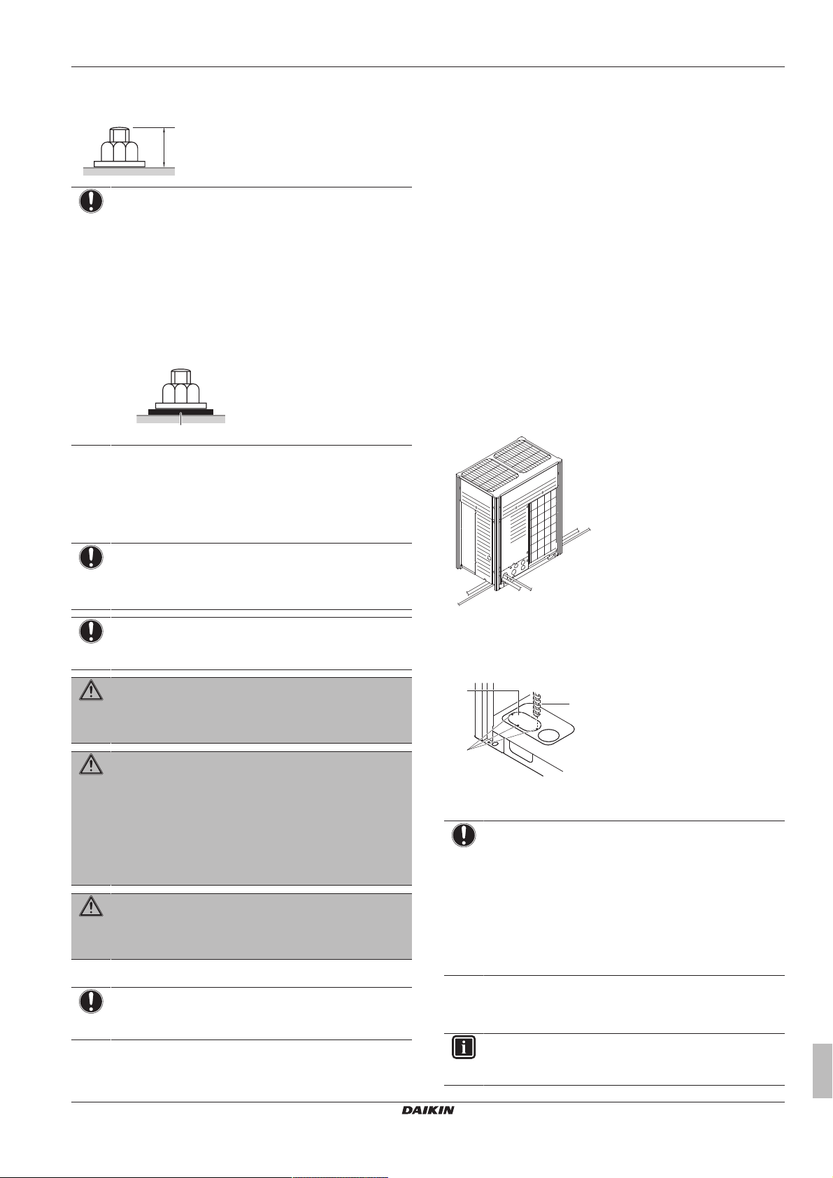
6 Installation
20 mm
a
a b
c
c
b
a
▪ Fasten the unit in place using four foundation bolts M12. It is best
to screw in the foundation bolts until their length remains 20mm
above the foundation surface.
NOTICE
▪ Prepare a water drainage channel around the
foundation to drain waste water from around the unit.
During heating operation and when the outdoor
temperatures are negative, the drained water from the
outdoor unit will freeze up. If the water drainage is not
taken care of, the area around the unit might be very
slippery.
▪ When installed in a corrosive environment, use a nut
with plastic washer (a) to protect the nut tightening part
from rust.
6.4 Connecting the refrigerant piping
6.4.2 About connecting the refrigerant piping
Before connecting the refrigerant piping, make sure the outdoor and
indoor units are mounted.
Connecting the refrigerant piping involves:
▪ Routing and connecting the refrigerant piping to the outdoor unit
▪ Protecting the outdoor unit against contamination
▪ Connecting the refrigerant piping to the indoor units (see the
installation manual of the indoor units)
▪ Connecting the multi-connection piping kit
▪ Connecting the refrigerant branching kit
▪ Keeping in mind the guidelines for:
▪ Brazing
▪ Using the stop valves
▪ Removing the pinched pipes
6.4.3 To route the refrigerant piping
Installation of refrigerant piping is possible as front connection or
side connection (when taken out from the bottom) as shown in the
figure below.
6.4.1 Precautions when connecting the refrigerant piping
NOTICE
Make sure refrigerant piping installation complies with
applicable legislation. In Europe, EN378 is the applicable
standard.
NOTICE
Make sure the field piping and connections are NOT
subjected to stress.
WARNING
During tests, NEVER pressurize the product with a
pressure higher than the maximum allowable pressure (as
indicated on the nameplate of the unit).
WARNING
Take sufficient precautions in case of refrigerant leakage. If
refrigerant gas leaks, ventilate the area immediately.
Possible risks:
▪ Excessive refrigerant concentrations in a closed room
can lead to oxygen deficiency.
▪ Toxic gas may be produced if refrigerant gas comes
into contact with fire.
WARNING
ALWAYS recover the refrigerant. Do NOT release them
directly into the environment. Use a vacuum pump to
evacuate the installation.
▪ Only use phosphoric acid deoxidised seamless copper.
a Left-side connection
b Front connection
c Right-side connection
For side connections, the knockout hole on the bottom plate should
be removed:
a Large knockout hole
b Drill
c Points for drilling
NOTICE
Precautions when making knockout holes:
▪ Avoid damaging the casing.
▪ After making the knockout holes, we recommend you
remove the burrs and paint the edges and areas
around the edges using repair paint to prevent rusting.
▪ When passing electrical wiring through the knockout
holes, wrap the wiring with protective tape to prevent
damage.
RXYTQ8~16U7YF
VRV IV+ heat pump for high ambient temperatures
4P561157-1 – 2018.09
NOTICE
After all the piping has been connected, make sure there is
no gas leak. Use nitrogen to perform a gas leak detection.
6.4.4 To connect the refrigerant piping to the outdoor unit
INFORMATION
All local inter unit piping are field supplied except the
accessory pipes.
Installer and user reference guide
19
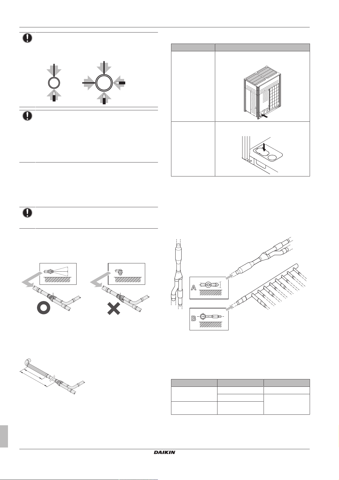
6 Installation
1
1
1
1
2 2
≤Ø25.4 >Ø25.4
a
a
A B
7.5°
7.5°
>120 mm
>500 mm
A
B
±
3
0
°
a
b
c
a
NOTICE
Precautions when connecting field piping. Add brazing
material as shown in the figure.
NOTICE
▪ Be sure to use the supplied accessory pipes when
carrying out piping work in the field.
▪ Be sure that the field installed piping does not touch
other pipes, the bottom panel or side panel. Especially
for the bottom and side connection, be sure to protect
the piping with suitable insulation, to prevent it from
coming into contact with the casing.
Connect the stop valves to the field piping using the accessory pipes
supplied with the unit.
The connections to the branch kits are the responsibility of the
installer (field piping).
6.4.5 To connect the multi connection piping kit
NOTICE
Improper installation may lead to malfunction of the
outdoor unit.
▪ Install the joints horizontally, so that the caution label (a) attached
to the joint comes to the top.
▪ Do not tilt the joint more than 7.5° (see view A).
▪ Do not install the joint vertically (see view B).
6.4.6 Multiple outdoor units: Knockout holes
Connection Description
Front connection Remove the front plate knockout holes to
connect.
Bottom connection Remove the knockout holes on the bottom
frame and route the piping under the bottom.
6.4.7 To connect the refrigerant branching kit
For installation of the refrigerant branching kit, refer to the installation
manual delivered with the kit.
▪ Mount the refnet joint so that it branches either horizontally or
vertically.
▪ Mount the refnet header so that it branches horizontally.
a Caution label
X Not allowed
O Allowed
▪ Make sure that the total length of the piping connected to the joint
is absolute straight for more than 500mm. Only if a straight field
piping of more than 120 mm is connected, more than 500 mm of
straight section can be ensured.
Installer and user reference guide
20
a Horizontal surface
b Refnet joint mounted vertically
c Refnet joint mounted horizontally
6.4.8 To protect against contamination
Protect the piping as described in the following table to prevent dirt,
liquid or dust from entering the piping.
Unit Installation period Protection method
Outdoor unit >1month Pinch the pipe
<1month Pinch or tape the pipe
Indoor unit Regardless of the
period
Seal the piping and wiring intake holes using sealing material (field
supply), otherwise the capacity of the unit will drop and small
animals may enter the machine.
Example: passing piping out through the front.
RXYTQ8~16U7YF
VRV IV+ heat pump for high ambient temperatures
4P561157-1 – 2018.09
 Loading...