

Daikin RXYQ-PYLK Installation manuals

INSTALLATION MANUAL
System air conditioner
RXYQ8P7Y1K
RXYQ10P7Y1K
RXYQ12P7Y1K
RXYQ8P7YLK
RXYQ10P7YLK
RXYQ12P7YLK
1 2
B
b
ac
AC
a e
AC
d
D
21
B
b
e
c a ce
AC
d
3
B
b
f
D
d
D
4
B
b
2
d
3
b
D
3
5
3
5
5
3
1
1
2
3
4
1
4
3
5
1
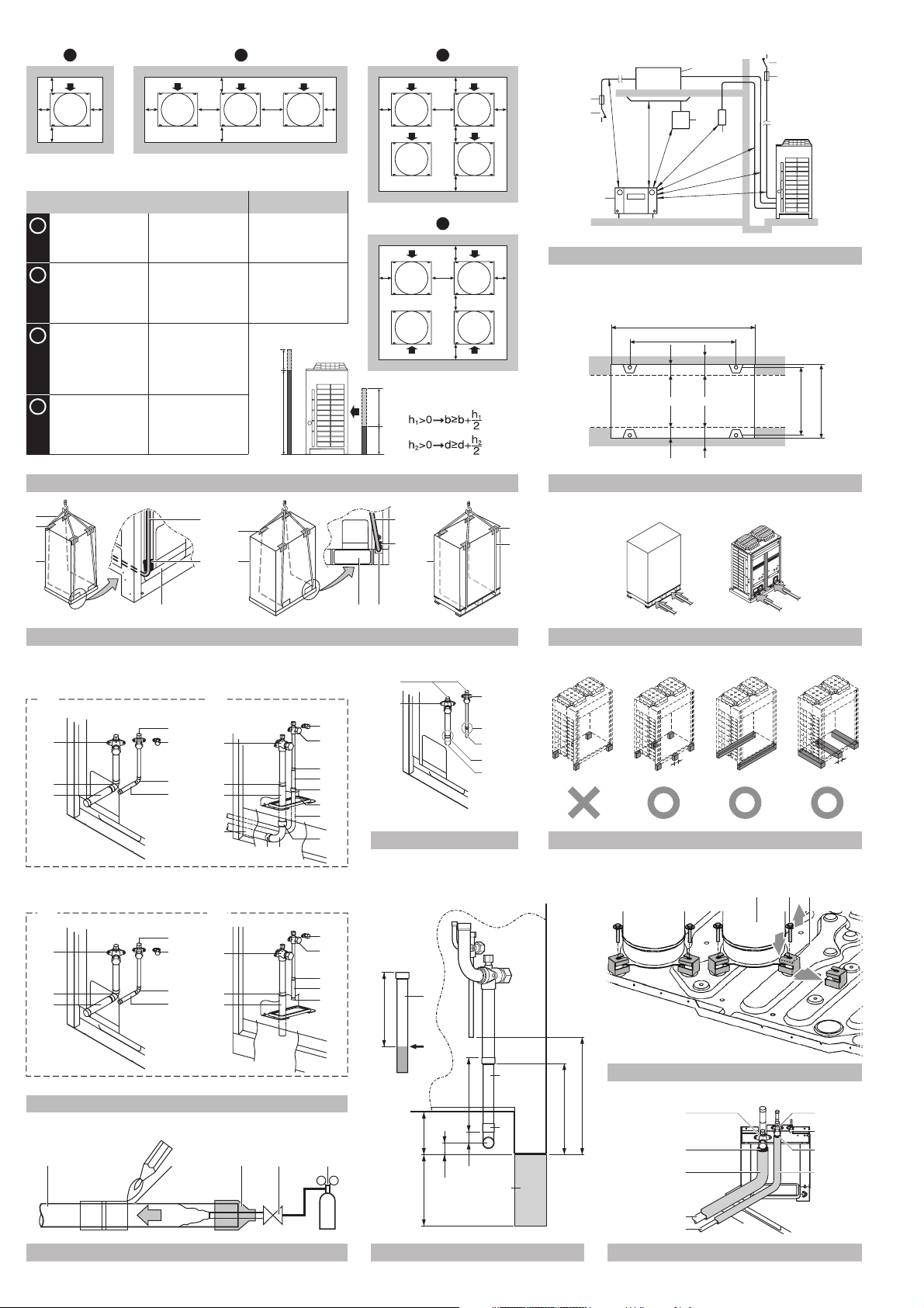
a ≥10 mm
b ≥300 mm
c ≥10 mm
d ≥500 mm
a ≥10 mm
b ≥300 mm
c ≥10 mm
d ≥500 mm
e ≥20 mm
a ≥10 mm
b ≥300 mm
c ≥10 mm
d ≥500 mm
e ≥20 mm
f ≥600 mm
a ≥10 mm
b ≥300 mm
c ≥10 mm
d ≥500 mm
e ≥20 mm
A+B+C+D A+B
a ≥50 mm
b ≥100 mm
c ≥50 mm
d ≥500 mm
a ≥50 mm
b ≥100 mm
c ≥50 mm
d ≥500 mm
e ≥100 mm
a ≥50 mm
b ≥100 mm
c ≥50 mm
d ≥500 mm
e ≥100 mm
f ≥500 mm
a ≥50 mm
b ≥100 mm
c ≥50 mm
d ≥500 mm
e ≥100 mm
3
5
5
1
a ≥200 mm
b ≥300 mm
a ≥200 mm
b ≥300 mm
e ≥400 mm
h
2
1500
a ce
AC
h
1
500
6
3
2
2
3
4
5
≥1000
≥1000
≥1500
1
≥1000
≥1500
≥1500
≥1500
(mm)
A
B
6767
≥67≥67
765
722-737
2
4
8
RXYQ8~12
A B
2
1
8
4
3
8
6
RXYQ16~32
A B
2
1
8
4
3
8
6
24
5
6
3
2
3
1
8
5
9
2
8
7
8
11
10
8
6
2
4
1
4
1
7
≥100
≥100
7
98
11
3
1
8
5
2
8
7
8
1
A
9
BA C
1
3
2
2
8
10
12456
3
7
10 11
90
150
25
1
AB
C
3
9
12
D
1
2
3
4
5
4
5
4
6
6
12
8
13
A
B
14
±
3
0
1
°
1
1 2
17
max
15°
A
1
B
345
1
13
15
1
B
2
2
3
B
1
4
5
6
3
6
15
18
1
1
19
A1P
A B C
1 267
ABC F1 F2 F1 F2 Q1 Q2
3
4
2
6
5
18
21
12345
3
4
19 20
22
5
1
2
21
24
5
3
4
1
2
6
3
4
22
25
RXYQ8 RXYQ10~12
14
16
111
AB
8
2
2
2
2
16
ABC F1 F1F2 F2 Q1 Q2
C/H SELECTOR
F1 F2 F1 F2 F1 F2
F1 F2 F1 F2 F1 F2
L1 L2 L3 N
TO IN/D UNIT
TO OUT/D UNIT TO MULTI UNIT
8
9
4
2
5
7
6
7
2
3
>120 mm
>500 mm
17
20
213
A1P
ABC F1F2F1F2Q1Q2 Q1Q2
6
7
23
TO IN/D
UNIT
5
6
F1 F2
445
ON
OFF
Q1 Q2
O
U
T
1234
I
N
DS1
7
10
11
F1 F2 P1 P2
P1 P2
1
23
26
A B C
ON
OFF
O
U
T
1234
I
N
DS1
2
6
1 2 1 2
A B C
1
24 25 26
■
■
■
RXYQ8P7Y1K RXYQ8P7YLK
RXYQ10P7Y1K RXYQ10P7YLK
RXYQ12P7Y1K RXYQ12P7YLK
VRVIII System air conditioner
Installation manual
ONTENTS
C
P
1. Introduction................................................................................ 1
1.1. Combination.................................................................................1
1.2. Standard supplied accessories .................................................... 2
1.3. Optional accessories.................................................................... 2
1.4. Technical and Electrical specifications.........................................2
2. Main components...................................................................... 2
3. Selection of location .................................................................. 3
4. Inspecting and handling the unit................................................ 4
5. Unpacking and placing the unit ................................................. 4
6. Refrigerant piping...................................................................... 4
6.1. Installation tools ...........................................................................5
6.2. Selection of piping material..........................................................5
6.3. Pipe connection............................................................................5
6.4. Connecting the refrigerant piping.................................................5
6.5. Protection against contamination when installing pipes............... 7
6.6. Example of connection................................................................. 8
7. Leak test and vacuum drying .................................................. 10
8. Field wiring .............................................................................. 10
8.1. Internal wiring – Parts table........................................................ 11
8.2. Optional parts cool/heat selector................................................11
8.3. Power circuit and cable requirements ........................................12
8.4. General cautions........................................................................12
8.5. System examples....................................................................... 13
8.6. Leading power line and transmission line ..................................13
8.7. Field line connection: transmission wiring and
cool/heat selection .....................................................................13
8.8. Field line connection: power wiring ............................................ 15
8.9. Wiring example for wiring inside unit.......................................... 15
9. Pipe insulation......................................................................... 16
10. Checking of unit and installation conditions ............................ 16
11. Charging refrigerant ................................................................ 16
11.1. Precautions when adding R410A............................................... 16
11.2. Stop valve operation procedure ................................................. 17
11.3. How to check how many units are connected............................ 17
11.4. Additional refrigerant charge......................................................18
11.6. Checks after adding refrigerant.................................................. 23
12. Before operation...................................................................... 24
12.1. Service precautions.................................................................... 24
12.2. Checks before initial start-up...................................................... 24
12.3. Field setting................................................................................ 24
12.4. Test operation............................................................................. 26
13. Service mode operation .......................................................... 28
14. Caution for refrigerant leaks.................................................... 29
15. Disposal requirements............................................................. 29
READ THIS MANUAL ATTENTIVELY BEFORE STARTING
UP THE UNIT. DO NOT THROW IT AWAY. KEEP IT IN YOUR
FILES FOR FUTURE REFERENCE.
IMPROPER INSTALLATION OR ATTACHMENT OF
EQUIPMENT OR ACCESSORIES COULD RESULT IN
ELECTRIC SHOCK, SHORT-CIRCUIT, LEAKS, FIRE OR
OTHER DAMAGE TO THE EQUIPMENT. BE SURE ONLY
TO USE ACCESSORIES MADE BY
DAIKIN
WHICH ARE
SPECIFICALLY DESIGNED FOR USE WITH THE
EQUIPMENT AND HAVE THEM INSTALLED BY A
PROFESSIONAL.
DAIKIN
EQUIPMENT IS DESIGNED FOR COMFORT
APPLICATIONS. FOR USE IN OTHER APPLICATIONS,
PLEASE CONTACT YOUR LOCAL
DAIKIN
DEALER.
IF UNSURE OF INSTALLATION PROCEDURES OR USE,
ALWAYS CONTACT YOUR DEALER FOR ADVICE AND
INFORMATION.
THIS AIR CONDITIONER COMES UNDER THE TERM
"APPLIANCES NOT ACCESSIBLE TO THE GENERAL
PUBLIC".
age
The refrigerant charge of the system must be less than
100 kg. This means that in case the calculated refrigerant
charge is equal to or more than 95 kg you must divide your
multiple outdoor system into smaller independent systems,
each containing less than 95 kg refrigerant charge.
For factory charge, refer to the unit name plate.
The refrigerant R410A requires strict cautions for keeping
the system clean, dry and tight.
Clean and dry
Foreign materials (including mineral oils such as
SUNISO oil or moisture) should be prevented from
getting mixed into the system.
Tight
R410A does not contain any chlorine, does not
destroy the ozone layer, and does not reduce the
earth's protection against harmful ultraviolet radiation.
R410A can contribute slightly to the greenhouse
effect if it is released. Therefore we should take
special attention to check the tightness of the
installation.
Read "6. Refrigerant piping" on page 4 carefully and follow
these procedures correctly.
Since design pressure is 4.0 MPa or 40 bar (for R407C
units: 3.3 MPa or 33 bar), pipes of larger wall thickness
may be required. The wall thickness of piping must be
carefully selected, refer to paragraph "6.2. Selection of
piping material" on page 5 for more details.
1. I
NTRODUCTION
This installation manual concerns VRV inverters of the Daikin
RXYQ-P7 series. These units are designed for outdoor installation
and used for cooling and heat pump applications. The RXYQ-P7
series can be combined from 3 main units and has nominal cooling
capacities ranging from 17.7 to 81.6 kW and nominal heating
capacities ranging from 25.0 to 112.5 kW.
The RXYQ-P7 units can be combined with Daikin VRV indoor units
for air conditioning purposes, and suitable for R410A.
The present installation manual describes the procedures for
unpacking, installing and connecting the RXYQ-P7 units. Installation
of the indoor units is not described in this manual. Always refer to the
installation manual supplied with these units for their installation.
1.1. Combination
The indoor units can be installed in the following range.
Always use appropriate indoor units compatible with R410A.
To learn which models of indoor units are compatible with
R410A, refer to the product catalogs.
■
Pay attention when connecting outdoor units in multi
combination. RXYQ-M units are NOT compatible with RXYQ-P
units.
■
RXYQ_Y1K units are NOT compatible with RXYQ_YLK units.
Installation manual
1
RXYQ8~12P7Y1K + RXYQ8~12P7YLK
VRVIII System air conditioner
4PW41760-1
■
■
■
■
■
■
■
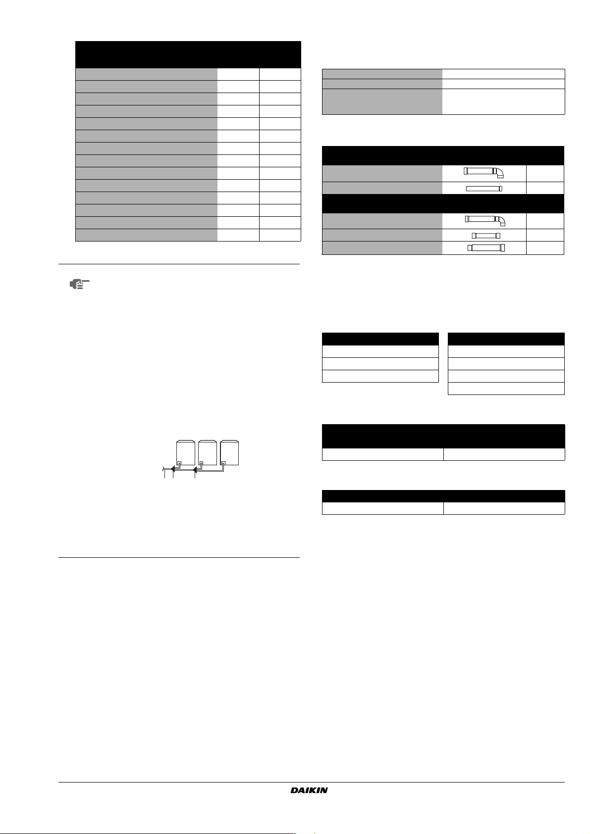
Total capacity/quantity of indoor units
Tot al
capacity of
Standard combination of outdoor units
RXYQ8
RXYQ10
RXYQ12
RXYQ16 = RXYQ8 + RXYQ8
RXYQ18 = RXYQ8 + RXYQ10
RXYQ20 = RXYQ10 + RXYQ10
RXYQ22 = RXYQ10 + RXYQ12
RXYQ24 = RXYQ12 + RXYQ12
RXYQ26 = RXYQ8 + RXYQ8 + RXYQ10
RXYQ28 = RXYQ8 + RXYQ10 + RXYQ10
RXYQ30 = RXYQ8 + RXYQ10 + RXYQ12
RXYQ32 = RXYQ10 + RXYQ10 + RXYQ12
RXYQ34 = RXYQ10 + RXYQ12 + RXYQ12
RXYQ36 = RXYQ12 + RXYQ12 + RXYQ12 450~1170 58
NOTE
(a)
(a)
(a)
(a) Main unit
The table above shows the possible total capacity
indoor units
100~260 13
125~325 16
150~390 19
200~520 26
225~585 29
250~650 32
275~715 35
300~780 39
325~845 42
350~910 45
375~975 48
400~1040 52
425~1105 55
and number of possible indoor units when
configured in a standard combination.
If the total capacity of the connected indoor units
exceeds the capacity of the outdoor unit, cooling
and heating performance may drop when running
the indoor units.
Refer to the section on performance characteristics in the Engineering Data Book for details.
There are restrictions on the refrigerant pipe
connection order between outdoor units during
installation in case of a multiple outdoor unit
system.
Install according to the following restrictions.
The capacities of outdoor units A, B, and C must
fulfill the following restriction conditions: A ≥ B ≥ C .
ABC
12 3
1 To indoor units
2 Outdoor unit multi connection piping kit (first
branch)
3 Outdoor unit multi connection piping kit
(second branch)
Tot al
quantity of
indoor units
1.2. Standard supplied accessories
See location 1 in figure 25 for reference to where following
accessories are supplied with the unit.
Installation manual 1
Operation manual 1
Request for indication of additional
refrigerant charging and leak detection
amount label
1
See location 2 in figure 25 for reference to where following
accessories are supplied with the unit.
Unit type Item Quantity
8~12 Hp 1
8~12 Hp 1
Unit type Item Quantity
8~12 Hp 1
8~10 Hp 1
12 Hp 1
Gas side accessory pipe
Liquid side accessory pipe
1.3. Optional accessories
To install the above outdoor units, the following optional parts are
also required.
Refrigerant branching kit (for R410A only: Always use an
appropriate kit dedicated for your system.)
Refnet header Refnet joint
KHRQ22M29H KHRQ22M20T
KHRQ22M64H KHRQ22M29T9
KHRQ22M75H KHRQ22M64T
KHRQ22M75T
Outdoor unit multi connection piping kit (For R410A only: Always
use an appropriate kit dedicated for your system.)
Number of outdoor units connected
2 3
BHFQ22P1007 BHFQ22P1517
Pipe size reducer (For R410A only: Always use an appropriate
kit dedicated for your system.)
RXYQ24~36
KHRQ22M75T KHRQ22M75H
To select an optimum refrigerant branching kit, refer to "6. Refrigerant
piping" on page 4.
RXYQ8~12P7Y1K + RXYQ8~12P7YLK
VRVIII System air conditioner
4PW41760-1
1.4. Technical and Electrical specifications
Refer to the Engineering Data Book for the complete list of
specifications.
AIN
2. M
For main components and function of the main components, refer to
the Engineering Data Book.
COMPONENTS
Installation manual
2
1
2
■
■
3
4
■
■
5
6
7
8
9
■
10
■
■
■
■
3. S
This unit, both indoor and outdoor, is suitable for installation in a
commercial and light industrial environment. If installed as a household appliance it could cause electromagnetic interference, in which
case the user may be required to take adequate measures.
Obtain the customer's permission before installing.
The inverter units should be installed in a location that meets the
following requirements:
ELECTION
Make sure to provide for adequate measures in order
to prevent that the outdoor unit be used as a shelter
by small animals.
Small animals making contact with electrical parts can
cause malfunctions, smoke or fire. Please instruct the
customer to keep the area around the unit clean.
The foundation is strong enough to support the weight of the unit
and the floor is flat to prevent vibration and noise generation.
If not, the unit may fall over and cause damage or
injury.
The space around the unit is adequate for servicing and the
minimum space for air inlet and air outlet is available. (Refer to
figure 1 and choose one of the possibilities).
A B C D Sides along the installation site with obstacles
In case of an installation site where sides A+B+C+D have
obstacles, the wall heights of sides
service space dimensions. Refer to figure 1 for impact of wall
heights of sides B+D on service space dimensions.
In case of an installation site where only the sides A+B have
obstacles, the wall heights have no influence on any
indicated service space dimensions.
NOTE
Make sure that there is no danger of fire due to leakage of
inflammable gas.
Ensure that water can not cause any damage to the location in
case it drips out the unit (e.g. in case of a blocked drain pipe).
The piping length between the outdoor unit and the indoor unit
may not exceed the allowable piping length. (Refer to
"6.6. Example of connection" on page 8)
Select the location of the unit in such a way that neither the
discharged air nor the sound generated by the unit disturbs
anyone.
Make sure that the air inlet and outlet of the unit are not
positioned towards the main wind direction. Frontal wind will
disturb the operation of the unit. If necessary, use a windscreen
to block the wind.
Do not install or operate the unit on locations where air contains
high levels of salt, like e.g. in the vicinity of oceans. (Refer for
further information to the engineering databook).
During installation, avoid the possibility that anybody can climb
on the unit or place objects on the unit.
Falls may result in injury.
When installing the unit in a small room, take measures in order
to keep the refrigerant concentration from exceeding allowable
safety limits in the event of a refrigerant leak.
OF
LOCATION
Suction side
A+C
have no impact on
The service space dimensions in figure 1 are
based on cooling operation at 35°C.
The equipment described in this manual may cause
electronic noise generated from radio-frequency
energy. The equipment complies to specifications that
are designed to provide reasonable protection against
such interference. However, there is no guarantee that
interference will not occur in a particular installation.
It is therefore recommended to install the equipment
and electric wires keeping proper distances away from
stereo equipment, personal computers, etc...
(See figure 2).
1 Personal computer or radio
2 Fuse
3 Earth leakage breaker
4 Remote controller
5 Cool/heat selector
6 Indoor unit
In places with weak reception, keep distances of 3 m
or more to avoid electromagnetic disturbance of other
equipment and use conduit tubes for power and
transmission lines.
In heavy snowfall areas, select an installation site
where snow will not affect the operation of the unit.
The refrigerant R410A itself is nontoxic, nonflammable
and is safe. If the refrigerant should leak however, its
concentration may exceed the allowable limit
depending on room size. Due to this, it could be
necessary to take measures against leakage. Refer to
the chapter "14. Caution for refrigerant leaks" on
page 29.
Do not install in the following locations.
• Locations where sulfurous acids and other
corrosive gases may be present in the atmosphere.
Copper piping and soldered joints may corrode,
causing refrigerant to leak.
• Locations where a mineral oil mist, spray or vapour
may be present in the atmosphere.
Plastic parts may deteriorate and fall off or causing
water leakage.
• Locations where equipment that produces electromagnetic waves is found.
The electromagnetic waves may cause the control
system to malfunction, preventing normal
operation.
• Locations where flammable gases may leak, where
thinner, gasoline, and other volatile substances are
handled, or where carbon dust and other
incendiary substances are found in the
atmosphere.
Leaked gas may accumulate around the unit,
causing an explosion.
When installing, take strong winds, typhoons or
earthquakes into account.
Improper installation may result in fall over of the unit.
Installation manual
3
Excessive refrigerant concentrations in a closed room
can lead to oxygen deficiency.
RXYQ8~12P7Y1K + RXYQ8~12P7YLK
VRVIII System air conditioner
4PW41760-1
4. I
At delivery, the package should be checked and any damage should
be reported immediately to the carrier claims agent.
When handling the unit, take into account the following:
5.1 From the moment you use a forklift to move the unit to its final
5.2 Once at final position, unpack the unit and pass the forklift arms
NSPECTING
Fragile, handle the unit with care.
Keep the unit upright in order to avoid compressor
damage.
Choose on beforehand the path along which the unit is to be
brought in.
Bring the unit as close as possible to its final installation position
in its original package to prevent damage during transport. (See
figure 4)
1 Packaging material
2 Opening (large)
3 Belt sling
4 Opening (small) (40x45)
5 Protector
Lift the unit preferably with a crane and 2 belts of at least 8 m
long. (See figure 4)
Always use protectors to prevent belt damage and pay attention
to the position of the unit's centre of gravity.
NOTE
If a forklift is to be used, preferably transport the unit with pallet
first, then pass the forklift arms through the large rectangular
openings on the bottom of the unit. (See figure 5)
position, lift the unit under the pallet.
through the large rectangular openings on the bottom of the unit.
NOTE
AND
HANDLING
Use a belt sling of ≤20 mm wide that adequately
bears the weight of the unit.
Use filler cloth on the forklift arms to prevent
damaging the unit. If the paint on the bottom
frame peels off, the anti corrosion effect may
decrease.
THE
UNIT
4
1
2
3
4
5
■
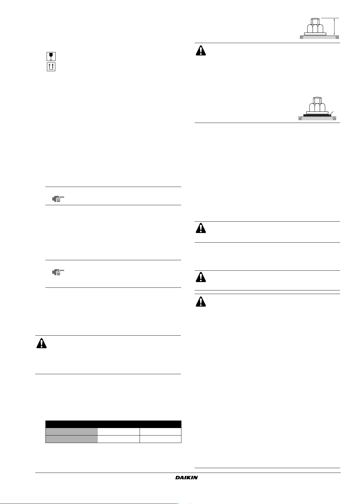
Fasten the unit in place using four foundation
bolts M12. It is best to screw in the foundation
bolts until their length remains 20 mm above
the foundation surface.
■ Prepare a water drainage channel around the
foundation to drain waste water from around the unit.
■ If the unit is to be installed on a roof, check the
strength of the roof and its drainage facilities first.
■ If the unit is to be installed on a frame, install the
waterproofing board within a distance of 150 mm
under the unit in order to prevent infiltration of water
coming from under the unit.
■ When installed in a corrosive
environment, use a nut with
plastic washer (1) to protect the
nut tightening part from rust.
20 mm
1
Method for removing transportation stays
(only for RXYQ10 and RXYQ12 units)
The 4 yellow transportation stays installed over the compressor legs
for protecting the unit during transport must be removed. Proceed as
shown in figure 9 and described below.
A Compressor
B Fixing nut
C Tr ansportation stay
1 Slightly loosen the fixing nut (B).
2 Remove the transportation stay (C) as shown in figure 9.
3 Tighten the fixing nut (B) again.
CAUTION
If the unit is operated with the transportation stay attached,
abnormal vibration or noise may be generated.
6. REFRIGERANT PIPING
Do not insert fingers, rods or other objects into the air
inlet or outlet. When the fan is rotating at high speed, it
will cause injury.
■
■
■
■
5. U
■ The unit must be installed on a solid longitudinal foundation
■ Support the unit with a foundation of 67 mm wide or more. (The
NPACKING
Remove the four screws fixing the unit to the pallet.
Make sure the unit is installed level on a sufficiently strong base
to prevent vibration and noise.
Do not use stands to only support the corners. (See
figure 7)
O Allowed (units: mm)
Make sure the base under the unit is larger than the 765 mm of
the unit depth. (See figure 3)
The height of the foundation must at least be 150 mm from the
floor.
(steelbeam frame or concrete) as indicated in figure 3.
Model A B
RXYQ8 930 792
RXYQ10+12 1240 1102
support leg of the unit is 67 mm wide, see figure 3).
AND
X Not allowed
PLACING
THE
UNIT
Use R410A to add refrigerant.
All field piping must be installed by a licensed refrigeration
technician and must comply with relevant local and
national regulations.
Caution to be taken when brazing refrigerant piping
Do not use flux when brazing copper-to-copper refrigerant
piping. (Particularly for the HFC refrigerant piping)
Therefore, use the phosphor copper brazing filler metal
(BCuP) which does not require flux.
Flux has extremely harmful influence on refrigerant piping
systems. For instance, if the chlorine based flux is used, it
will cause pipe corrosion or, in particular, if the flux
contains fluorine, it will damage the refrigerant oil.
Be sure to perform a nitrogen blow when brazing. Brazing
without performing nitrogen replacement or releasing
nitrogen into the piping will create large quantities of
oxidized film on the inside of the pipes, adversely affecting
valves and compressors in the refrigerating system and
preventing normal operation.
After completing the installation work, check that the
refrigerant gas does not leak.
To xic gas may be produced if the refrigerant gas leaks into
the room and comes in contact with a source of fire.
Ventilate the area immediately in the event of a leak.
In the event of a leak, do not touch the leaked refrigerant
directly. Frostbite may be caused.
RXYQ8~12P7Y1K + RXYQ8~12P7YLK
VRVIII System air conditioner
4PW41760-1
Installation manual
6.1. Installation tools
6.3. Pipe connection
Make sure to use installation tools (gauge manifold charge hose,
etc.) that are exclusively used for R410A installations to withstand the
pressure and to prevent foreign materials (e.g. mineral oils such as
SUNISO and moisture) from mixing into the system.
(The screw specifications differ for R410A and R407C.)
Use a 2-stage vacuum pump with a non-return valve which can
evacuate to –100.7 kPa (5 Torr, –755 mm Hg).
NOTE
Make sure the pump oil does not flow oppositely into
the system while the pump is not working.
6.2. Selection of piping material
1. Foreign materials inside pipes (including oils for fabrication)
must be 30 mg/10 m or less.
2. Use the following material specification for refrigerant piping:
■ Size: determine the proper size referring to chapter
"6.6. Example of connection" on page 8.
■ Construction material: phosphoric acid deoxidized seamless
copper for refrigerant.
■ Temper grade: use piping with temper grade in function of the
pipe diameter as listed in the table below.
Pipe Ø Temper grade of piping material
≤15.9 O
≥19.1 1/2H
O = Annealed
1/2H = Half hard
Be sure to perform a nitrogen blow when brazing and to read the
paragraph "Caution to be taken when brazing refrigerant piping" on
page 4 first.
NOTE
The pressure regulator for the nitrogen released when
doing the brazing should be set to 0.02 MPa or less.
(See figure 10)
1 Refrigerant piping
2 Location to be brazed
3 Nitrogen
4 Taping
5 Manual valve
6 Regulator
7 Nitrogen
Do not use anti-oxidants when brazing the pipe joints.
Residue can clog pipes and break equipment.
6.4. Connecting the refrigerant piping
1Front connection or side connection
Installation of refrigerant piping is possible as front connection or
side connection (when taken out from the bottom) as shown in
the figure.
■ The pipe thickness of the refrigerant piping should comply
with relevant local and national regulations. The minimal pipe
thickness for R410A piping must be in accordance with the
table below.
Minimal thickness
Pipe Ø
6.4 0.80 22.2 0.80
9.5 0.80 28.6 0.99
12.7 0.80 34.9 1.21
15.9 0.99 41.3 1.43
19.1 0.80
t (mm)
Pipe Ø
Minimal thickness
t (mm)
3. Make sure to use the particular branches of piping that have
been selected referring to chapter "6.6. Example of connection"
on page 8.
4. In case the required pipe sizes (inch sizes) are not available, it is
also allowed to use other diameters (mm sizes), taken the
following into account:
■ select the pipe size nearest to the required size.
■ use the suitable adapters for the change-over from inch to
mm pipes (field supply).
5. Precautions when selecting branch piping
When the equivalent pipe length between outdoor and indoor
units is 90 m or more, the size of the main pipes (both gas side
and liquid side) must be increased.
Depending on the length of the piping, the capacity may drop,
but even in such a case it is possible to increase the size of the
main pipes. Refer to page 9. If the recommended pipe size is not
available, stick to the original pipe diameter (which may result in
a small capacity decrease).
12 3
1 Left-side connection
2 Front connection
3 Right-side connection
NOTE
Precautions when knocking out knock holes
■ Be sure to avoid damaging the casing
■ After knocking out the holes, we recommend you
remove the burrs and paint the edges and areas
around the edges using the repair paint to prevent
rusting.
■ When passing electrical wiring through the knock
holes, wrap the wiring with protective tape to
prevent damage.
2 Removing the pinched piping
When connecting refrigerant piping to the outdoor unit, first
remove the pinched piping. Do not vent gases into the
atmosphere.
Removing of the pinched piping must be carried out according to
the following procedure:
1. Make sure the stop valves are closed.
2. Connect a charge hose to the service ports of all stop
valves.
3. Recover the gas from the pinched piping.
4. When all the gas is recovered from the pinched piping,
dissolve the brazing using a burner and remove the
pinched piping.
Installation manual
5
Any gas remaining inside the stop valve may blow off
the pinched piping, causing damage or injury.
RXYQ8~12P7Y1K + RXYQ8~12P7YLK
VRVIII System air conditioner
4PW41760-1
See figure 6.
1 Pinched piping
2 Stop valve
3 Service port
4 Point of melting the brazing metal
NOTE
■ When connecting the piping on site, be sure to
use the accessory piping.
■ Make sure the onsite piping does not come into
contact with other piping, the bottom frame or side
panels of the unit.
Precautions when connecting field piping.
■ Perform brazing at the gas stop valve before
brazing at the liquid stop valve.
■ Add brazing material as shown in the figure.
■ Be sure to use the supplied accessory pipes
when carrying out piping work in the field.
■ Be sure that the field installed piping does not
touch other pipes, the bottom panel or side
panel. Especially for the bottom and side
connection, be sure to protect the piping with
suitable insulation, to prevent it from coming into
contact with the casing.
3 One outdoor unit installed: In case of RXYQ8~12
(See figure 8)
■ Front connection:
Remove the stop valve cover to connect.
■ Bottom connection:
Remove the knock holes on the bottom frame and route the
piping under the bottom frame.
A Front connection
Remove the stop valve cover to connect.
B Bottom connection:
Remove the knock holes on the bottom frame and route the piping
under the bottom frame
1 Gas pipe stop valve
2 Liquid pipe stop valve
3 Service port for adding refrigerant
4 Gas side accessory pipe (1)
5 Gas side accessory pipe (2)
6 Liquid side accessory pipe (1)
7 Liquid side accessory pipe (2)
8 Brazing
9 Gas side piping (field supply)
10 Liquid side piping (field supply)
11 Punch the knockout holes (use a hammer)
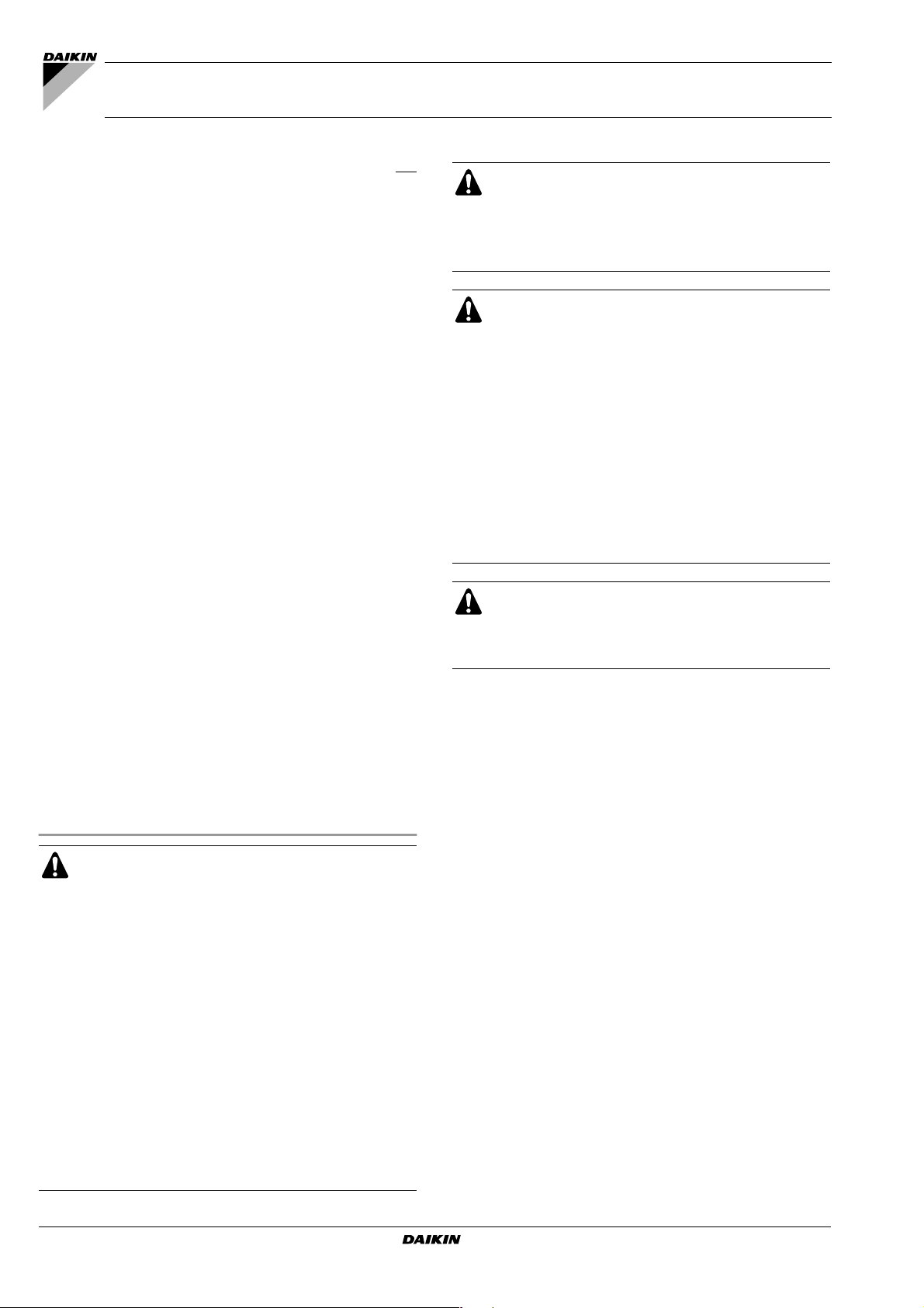
4 Outdoor units installed in a multiple outdoor unit system:
RXYQ16~36
■ Front connection:
Remove the stop valve cover to connect. (See figure 8)
■ Bottom connection:
Remove the knock holes on the bottom frame and route the
piping under the bottom frame. (See figure 8)
4.1 Precautions when connecting piping between outdoor
units (multiple outdoor unit system)
■ To connect the piping between outdoor units, an optional
multi connection piping kit BHFQ22P1007/1517 is always
required. When installing the piping, follow the instructions in
the installation manual that comes with the kit.
■ Only proceed with piping work after considering the
limitations on installing listed here and in the chapter
"6.4. Connecting the refrigerant piping" on page 5, always
referring to the installation manual delivered with the kit.
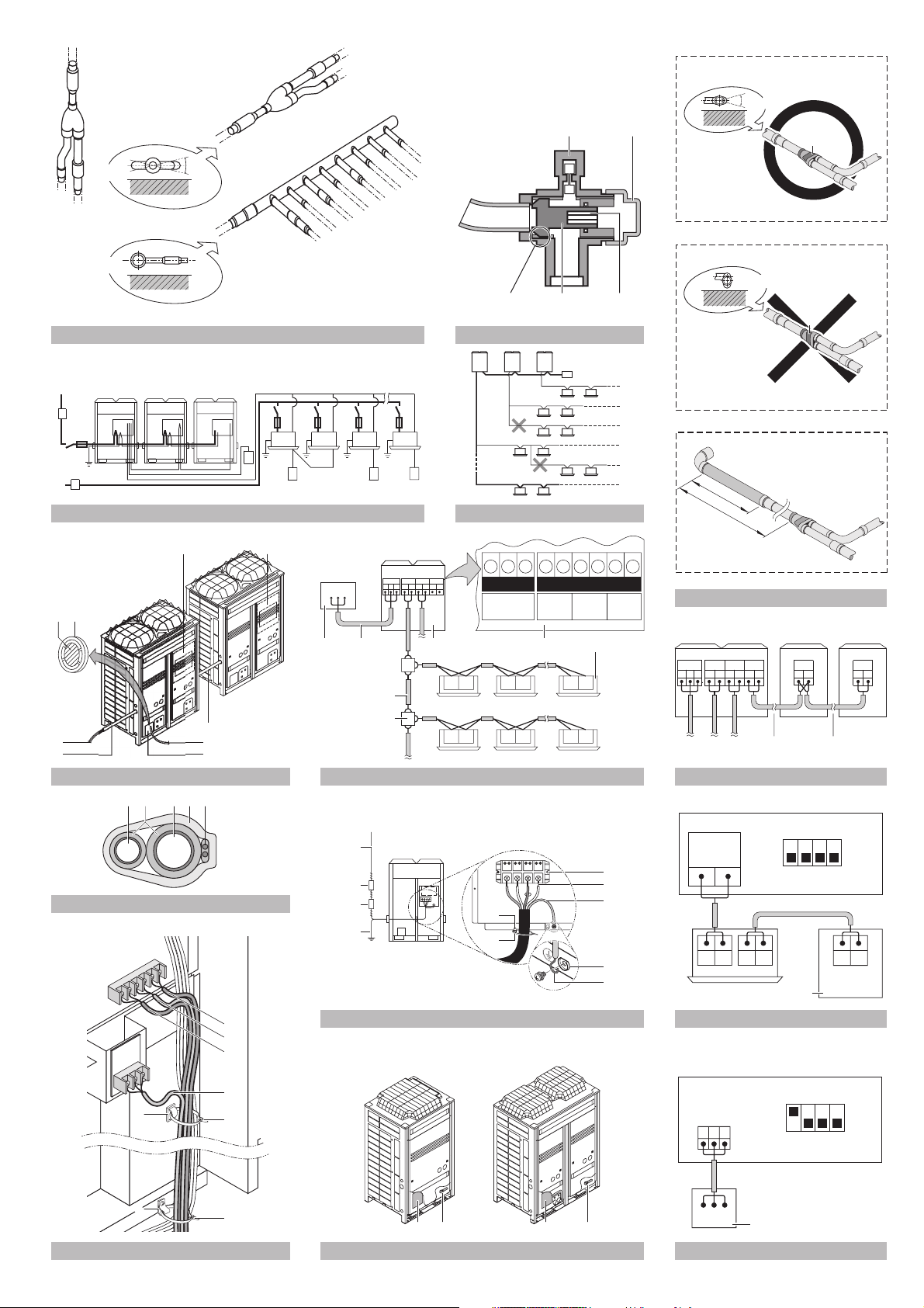
4.2 Possible installation patterns and configurations
■ The piping between the outdoor units must be routed level or
slightly upward to avoid the risk of oil retention into the piping
side.
Pattern 1
1
1
1 To indoor unit
Pattern 2
1
1
1 To indoor unit
Prohibited patterns: change to pattern 1 or 2.
1
1
2
1 To indoor unit
2 Piping between outdoor units
2
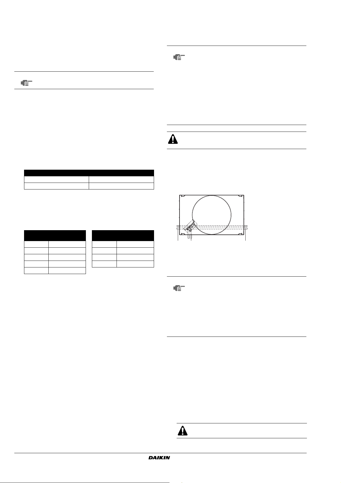
■ Processing the gas side accessory pipe (2)
Only in case of connecting at lateral side, cut the gas side
accessory pipe (2) as shown in figure 11.
1 Gas side accessory pipe
2 Cutting location
3 Gas side piping (field supply)
4 Base
Unit type A B C D
8 Hp
10 Hp
12 Hp
RXYQ8~12P7Y1K + RXYQ8~12P7YLK
VRVIII System air conditioner
4PW41760-1
(mm)
156 17 188 247
(mm)
150 29 192 247
(mm)
150 29 192 247
Installation manual
6
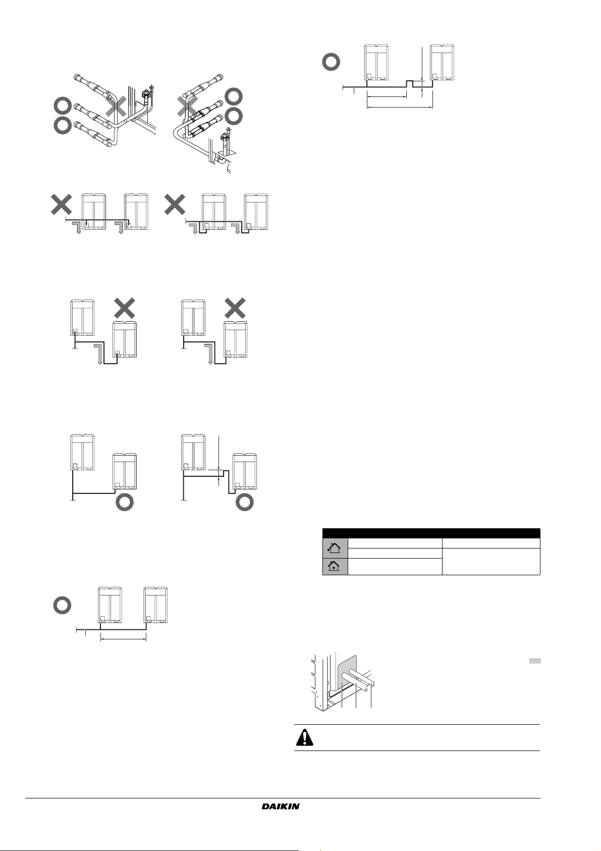
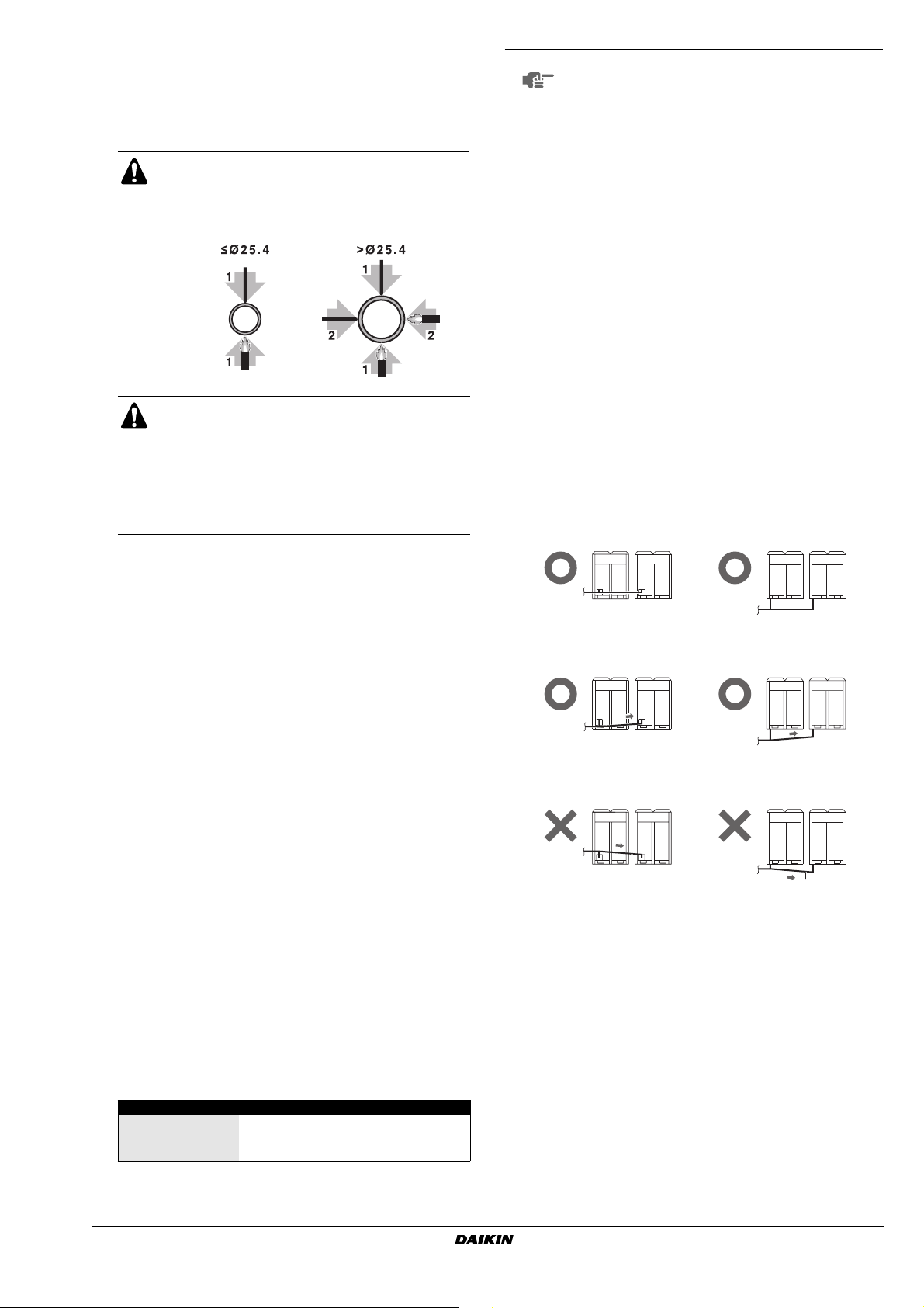
■ To avoid the risk of oil retention to the outmost outdoor unit,
h
always connect the stop valve and the piping between
outdoor units as shown in the 4 correct possibilities of the
figure below.
Prohibited patterns: change to pattern 1 or 2.
1
2 2
1 To indoor unit
2 Oil collects to the outmost outdoor unit.
1
22
Change to configuration as in figures below
11
22
1 To indoor unit
2 Oil collects to the outmost outdoor unit when the system
stops.
Correct configuration
≥200 mm
11
1 To indoor unit
■ If the piping length between the outdoor units exceeds 2 m,
create a rise of 200 mm or more in the gas line within a
length of 2 m from the kit.
- If ≤2 m
1
2
≤2 m
- If ≥2 m
≥200 mm
1
1 To indoor unit
2 Piping between outdoor units
≤2 m
2
≥2 m
5 Branching the refrigerant piping
■ For installation of the refrigerant branching kit, refer to the
installation manual delivered with the kit.
(See figure 13)
1 Horizontal surface
Follow the conditions listed below:
- Mount the refnet joint so that it branches either
horizontally or vertically.
- Mount the refnet header so that it branches horizontally.
■ Installation of the multi connection piping kit
(See figure 17)
- Install the joints horizontally, so that the caution label (1)
attached to the joint comes to the top.
Do not tilt the joint more than 15° (see view A).
Do not install the joint vertically (see view B).
- Make sure that the total length of the piping connected to
the joint is absolute straight for more than 500 mm. Only
if a straight field piping of more than 120 mm is
connected, more than 500 mm of straight section can be
ensured.
- Improper installation may lead to malfunction of the
outdoor unit.
6 Piping length restrictions
Make sure to perform the piping installation within the range of
the maximum allowable pipe length, allowable level difference
and allowable length after branching as indicated in
"6.6. Example of connection" on page 8.
6.5. Protection against contamination when installing pipes
-Take measures to prevent foreign materials like moisture and
contamination from mixing into the system.
Installation period Protection method
More than a month Pinch the pipe
Less than a month Pinch or tape the pipe
Regardless of the period
- Great caution is needed when passing copper tubes through
walls.
- Block all gaps in the holes for passing out piping and wiring
using sealing material (field supply). (The capacity of the unit
will drop and small animals may enter the machine.)
Example: passing piping out through the front
1 To indoor unit
2 Piping between outdoor units
Installation manual
7
1 Plug the areas marked with "
(When the piping is routed from t
front panel.)
2 Gas side piping
3 Liquid side piping
123
After all the piping has been connected, make sure there is
no gas leak. Use nitrogen to perform a gas leak check.
RXYQ8~12P7Y1K + RXYQ8~12P7YLK
VRVIII System air conditioner
4PW41760-1
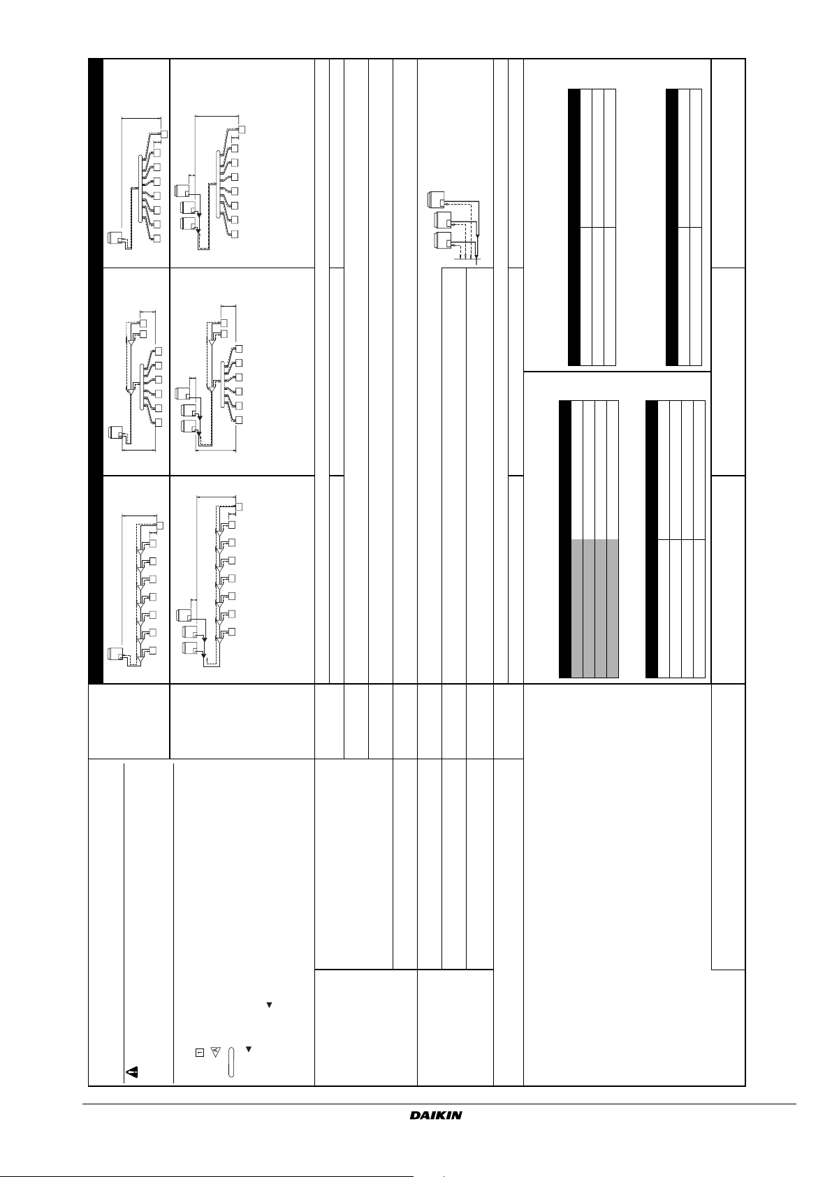
6.6. Example of connection
H1
i
8
H2
h
g
f
cde
a
123 4567
b
H1
i
8
H2
h
g
H3
f
a
cde
123 4567
b
r≤10 m (Approximate length:
max. 13 m)
s≤10 m (Approximate length:
max: 13 m)
rs t
t≤10 m (Approximate length:
max: 13 m)
(a)
[Example]
in case of refnet header;
indoor units 1+2+3+4+5+6+7+8
H2
k
78
j
B
h
g
i
b
A
123456
a
cde f
H1
p
H1
8
H2
g
Branch with refnet joint Branch with refnet joint and refnet header Branch with refnet header
1234567
hijklmn
ABCDEFG
ab c d e f
H3
H3
k
B
i
b
A
a
H1
H1
g
abcdef
j
p
EFG
D
ABC
H2
78
gh
de f
c
H2
7
123 456
hi j kl mn
8
123456
Pipe length between outdoor(*) and indoor units ≤165 m
[Example] unit 8: a+b+c+d+e+f+g+p≤165 m [Example] unit 6: a+b+h≤165 m, unit 8: a+i+k≤165 m [Example] unit 8: a+i≤165 m
Equivalent pipe length between outdoor(*) and indoor units ≤190 m (Assume equivalent pipe length of refnet joint to be 0.5 m and of the refnet header to be 1.0 m. (for
calculation purposes))
Total piping length from outdoor unit* to all indoor units ≤1000 m
(a) See note 2 on next page
units connected below the refnet header.
<290 KHRQ22M29H (Max. 8 branch)
290≤x<640 KHRQ22M64H (Max. 8 branch)
Indoor capacity type Refrigerant branch kit name
• Choose from the following table in accordance with the total capacity of all the indoor
• Note: 250 type cannot be connected below the refnet header.
How to select the refnet header
≥640 KHRQ22M75H (Max. 8 branch)
How to choose an outdoor multi connection piping kit (needed if the outdoor
[Example] unit 6: b+h≤40 m, unit 8: i+k≤40 m [Example] unit 8: i≤40 m
Choose from the following table in accordance with the capacity of the outdoor unit.
Outdoor unit capacity type Refrigerant branch kit name
RXYQ8 KHRQ22M20T
Difference in height between outdoor and indoor units (H1)≤50 m (≤40 m if outdoor unit is located in a lower
position).
Difference in height between adjacent indoor units (H2)≤15 m
Difference in height between outdoor unit (main) and outdoor unit (sub) (H3)≤5 m
[Example] unit 8: b+c+d+e+f+g+p≤40 m
Pipe length from first refrigerant branch kit (either refnet joint or refnet header) to indoor unit ≤40 m (See note 1 on next page)
How to select the refnet joint
•When using refnet joints at the first branch counted from the outdoor unit side.
RXYQ8+10 KHRQ22M29T9
the total capacity index.
RXYQ12 + RXYQ16~22 KHRQ22M64T
RXYQ24~36 KHRQ22M75T
•For refnet joints other than the first branch, select the proper branch kit model based on
Number of outdoor units Branch kit name
• Choose from the following table in accordance with the number of outdoor units.
unit capacity type is RXYQ16 or more.)
Indoor capacity type Refrigerant branch kit name
<200 KHRQ22M20T
2 BHFQ22P1007
3 BHFQ22P1517
[Example]
200≤x<290 KHRQ22M29T9
290≤x<640 KHRQ22M64T
≥640 KHRQ22M75T
[Example]
in case of refnet joint B; indoor units 7+8,
in case of refnet header; indoor units 1+2+3+4+5+6
in case of refnet joint C; indoor units 3+4+5+6+7+8
One outdoor unit
installed
(RXYQ8~12)
• Use the outdoor unit multi connection piping kit that is sold separately as an option
Example of connection
(Connection of 8 indoor units Heat pump system)
RXYQ8~12P7Y1K + RXYQ8~12P7YLK
VRVIII System air conditioner
4PW41760-1
Outdoor units
installed in a
multiple outdoor
unit system
(RXYQ16~36)
indoor unit
refnet joint
(BHFQ22P1007+1517) for the multi installation of outdoor units. Selection method is
as shown in the right table.
are sold separately as an option of the M-type series and do not use T-joints.
• Do not use the outdoor unit multi connection piping kit (BHFQ22M909+1359) that
refnet header
outdoor multi connection piping kit
Install the joint part ( part in the figure) of the outdoor unit multi connection piping kit
horizontally with attention to the installation restrictions described in "connecting the
refrigerant piping".
Actual pipe length
Equivalent length
Between outdoor and indoor units
(*) If the system capacity is RXYQ16 or more, re-read to the first outdoor branch as
seen from the indoor unit.
Maximum allowable length
Total extension
length
Actual pipe length Piping length from outdoor branch to outdoor unit ≤10 m. Approximate length: max. 13 m
Difference in
height
Difference in
height
Between outdoor branch and outdoor unit (Only for
RXYQ16 or more)
Between outdoor and indoor units
Between indoor and indoor units
Allowable height
Difference in
height
Between outdoor and outdoor units
Allowable length after the branch Actual pipe length
Refrigerant branch kit selection
Refrigerant branch kits can only be used with R410A.
Example of downstream indoor units
Installation manual
8
 Loading...