

Daikin FTXS60GV1B, FTXS71GV1B, RKS71FAV1B, RKS60F3V1B9, RXS60F3V1B Service Manual
...
Service
Manual
[Applied Models]
z Inverter Pair : Cooling Only
z Inverter Pair : Heat Pump
Inverter Pair
Wall Mounted Type FTXS-G Series
SiBE041011EC

SiBE041011EC
i Table of Contents
Inverter Pair
Wall Mounted Type
FTXS-G Series
zCooling Only
Indoor Unit
FTXS60GV1B FTXS71GV1B
Outdoor Unit
RKS60F3V1B RKS71FAV1B
RKS60F3V1B9
zHeat Pump
Indoor Unit
FTXS60GV1B FTXS71GV1B
Outdoor Unit
RXS60F3V1B RXS71FAV1B
RXS60F3V1B9 RXS71FAV1B9
RXS60F4V1B RXS71FAV1B8

SiBE041011EC
Table of Contents ii
1. Safety Cautions.......................................................................................v
1.1 Warnings and Cautions Regarding Safety of Workers............................. v
1.2 Warnings and Cautions Regarding Safety of Users............................... vii
2. Used Icons ..............................................................................................x
Part 1 List of Functions ................................................................1
1. Functions.................................................................................................2
1.1 Cooling Only.............................................................................................2
1.2 Heat Pump ...............................................................................................3
Part 2 Specifications .................................................................... 4
1. Specifications..........................................................................................5
1.1 Cooling Only.............................................................................................5
1.2 Heat Pump ...............................................................................................7
Part 3 Printed Circuit Board Connector Wiring Diagram ...........11
1. Indoor Unit.............................................................................................12
2. Outdoor Unit..........................................................................................14
2.1 RK(X)S60F3V1B, 71 Class ....................................................................14
2.2 RK(X)S60F3V1B9, RXS60F4V1B..........................................................16
Part 4 Function and Control........................................................18
1. Main Functions......................................................................................19
1.1 Temperature Control ..............................................................................19
1.2 Frequency Principle................................................................................19
1.3 Airflow Direction Control.........................................................................21
1.4 Fan Speed Control for Indoor Unit .........................................................22
1.5 Program Dry Operation ..........................................................................23
1.6 Automatic Operation...............................................................................24
1.7 Thermostat Control.................................................................................25
1.8 NIGHT SET Mode ..................................................................................26
1.9 ECONO Operation .................................................................................26
1.10 INTELLIGENT EYE Operation ...............................................................27
1.11 Inverter POWERFUL Operation .............................................................28
1.12 Clock Setting ..........................................................................................29
1.13 WEEKLY TIMER Operation ...................................................................30
1.14 Other Functions......................................................................................36
2. Function of Thermistor ..........................................................................37
3. Control Specification .............................................................................38
3.1 Mode Hierarchy ......................................................................................38
3.2 Frequency Control ..................................................................................39
3.3 Controls at Mode Changing / Start-up....................................................41
3.4 Discharge Pipe Temperature Control.....................................................43
3.5 Input Current Control ..............................................................................44
3.6 Freeze-up Protection Control .................................................................45
3.7 Heating Peak-cut Control .......................................................................45
3.8 Outdoor Fan Control...............................................................................46
3.9 Liquid Compression Protection Function................................................46
3.10 Defrost Control .......................................................................................47

SiBE041011EC
iii Table of Contents
3.11 Electronic Expansion Valve Control .......................................................48
3.12 Malfunctions ...........................................................................................51
Part 5 Remote Controller ............................................................52
1. Remote Controller .................................................................................53
Part 6 Service Diagnosis.............................................................55
1. General Problem Symptoms and Check Items .....................................57
2. Troubleshooting with LED.....................................................................58
2.1 Indoor Unit..............................................................................................58
2.2 Outdoor Unit ...........................................................................................58
3. Service Diagnosis .................................................................................59
4. Troubleshooting ....................................................................................62
4.1 Error Codes and Description ..................................................................62
4.2 Indoor Unit PCB Abnormality .................................................................63
4.3 Freeze-up Protection Control / Heating Peak-cut Control ......................64
4.4 Fan Motor (DC Motor) or Related Abnormality.......................................65
4.5 Thermistor or Related Abnormality (Indoor Unit)....................................67
4.6 Refrigerant Shortage ..............................................................................68
4.7 Low-voltage Detection or Over-voltage Detection..................................70
4.8 Signal Transmission Error (Between Indoor Unit and Outdoor Unit)......72
4.9 Signal Transmission Error on Outdoor Unit PCB
(RK(X)S60F3V1B, 71 Class Only) .........................................................74
4.10 Unspecified Voltage (Between Indoor Unit and Outdoor Unit) ...............75
4.11 Outdoor Unit PCB Abnormality...............................................................76
4.12 OL Activation (Compressor Overload) ...................................................78
4.13 Compressor Lock ...................................................................................80
4.14 DC Fan Lock ..........................................................................................81
4.15 Input Overcurrent Detection ...................................................................82
4.16 Four Way Valve Abnormality..................................................................83
4.17 Discharge Pipe Temperature Control.....................................................85
4.18 High Pressure Control in Cooling ...........................................................86
4.19 Compressor System Sensor Abnormality ..............................................87
4.20 Position Sensor Abnormality ..................................................................89
4.21 CT or Related Abnormality (RK(X)S60F3V1B, 71 Class Only) ..............92
4.22 Thermistor or Related Abnormality (Outdoor Unit) .................................94
4.23 Electrical Box Temperature Rise ............................................................96
4.24 Radiation Fin Temperature Rise ............................................................97
4.25 Output Overcurrent Detection ................................................................99
5. Check ..................................................................................................101
5.1 Thermistor Resistance Check ..............................................................101
5.2 Indoor Fan Motor Connector Output Check .........................................102
5.3 Power Supply Waveforms Check.........................................................102
5.4 Electronic Expansion Valve Check.......................................................102
5.5 Four Way Valve Performance Check ...................................................103
5.6 Inverter Unit Refrigerant System Check...............................................103
5.7 Inverter Analyzer Check .......................................................................104
5.8 Rotation Pulse Check on the Outdoor Unit PCB ..................................105
5.9 Installation Condition Check .................................................................106
5.10 Discharge Pressure Check...................................................................106

SiBE041011EC
Table of Contents iv
5.11 Outdoor Fan System Check .................................................................107
5.12 Main Circuit Short Check......................................................................107
5.13 Capacitor Voltage Check......................................................................108
5.14 Power Module Check ...........................................................................108
Part 7 Trial Operation and Field Settings................................. 110
1. Pump Down Operation........................................................................111
2. Forced Cooling Operation...................................................................112
3. Trial Operation ....................................................................................113
4. Field Settings ......................................................................................114
4.1 Model Type Setting ..............................................................................114
4.2 When 2 Units are Installed in 1 Room ..................................................114
4.3 Facility Setting (Cooling at Low Outdoor Temperature) .......................115
4.4 Jumper and Switch Settings .................................................................116
5. Silicon Grease on Power Transistor / Diode Bridge............................117
Part 8 Appendix.........................................................................118
1. Piping Diagrams..................................................................................119
1.1 Indoor Unit............................................................................................119
1.2 Outdoor Unit .........................................................................................119
2. Wiring Diagrams..................................................................................122
2.1 Indoor Unit............................................................................................122
2.2 Outdoor Unit .........................................................................................123

Safety Cautions SiBE041011EC
v
1. Safety Cautions
Be sure to read the following safety cautions before conducting repair work.
After the repair work is complete, be sure to conduct a test operation to ensure that the
equipment operates normally, and explain the cautions for operating the product to the
customer.
Caution Items The caution items are classified into Warning and Caution. The Warning items are
especially important since they can lead to death or serious injury if they are not followed
closely. The Caution items can also lead to serious accidents under some conditions if they
are not followed. Therefore, be sure to observe all the safety caution items described below.
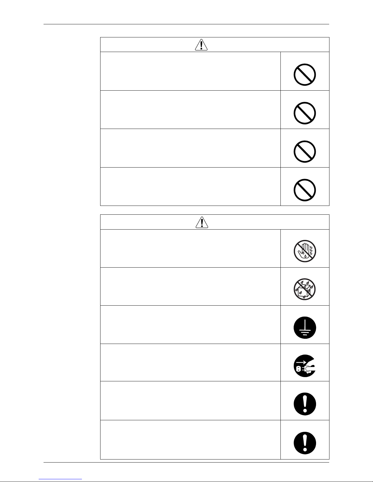
Pictograms This symbol indicates the item for which caution must be exercised.
The pictogram shows the item to which attention must be paid.
This symbol indicates the prohibited action.
The prohibited item or action is shown in the illustration or near the symbol.
This symbol indicates the action that must be taken, or the instruction.
The instruction is shown in the illustration or near the symbol.
1.1 Warnings and Cautions Regarding Safety of Workers
Warning
Do not store the equipment in a room with successive fire sources (e.g.,
naked flame, gas appliance, electric heater).
Be sure to disconnect the power cable plug from the plug socket before
disassembling the equipment for repair.
Working on the equipment that is connected to the power supply may cause an
electrical shock.
If it is necessary to supply power to the equipment to conduct the repair or
inspecting the circuits, do not touch any electrically charged sections of the
equipment.
If the refrigerant gas is discharged during the repair work, do not touch
the discharged refrigerant gas.
The refrigerant gas may cause frostbite.
When disconnecting the suction or discharge pipe of the compressor at
the welded section, evacuate the refrigerant gas completely at a wellventilated place first.
If there is gas remaining inside the compressor, the refrigerant gas or
refrigerating machine oil discharges when the pipe is disconnected, and it may
cause injury.
If the refrigerant gas leaks during the repair work, ventilate the area.
The refrigerant gas may generate toxic gases when it contacts flames.
Be sure to discharge the capacitor completely before conducting repair
work.
The step-up capacitor supplies high-voltage electricity to the electrical
components of the outdoor unit.
A charged capacitor may cause an electrical shock.
SiBE041011EC Safety Cautions
vi
Do not start or stop the air conditioner operation by plugging or
unplugging the power cable plug.
Plugging or unplugging the power cable plug to operate the equipment may
cause an electrical shock or fire.
Be sure to wear a safety helmet, gloves, and a safety belt when working
at a high place (more than 2 m).
Insufficient safety measures may cause a fall accident.
In case of R-32 / R-410A refrigerant models, be sure to use pipes, flare
nuts and tools for the exclusive use of the R-32 / R-410A refrigerant.
The use of materials for R-22 refrigerant models may cause a serious accident
such as a damage of refrigerant cycle as well as an equipment failure.
Do not mix air or gas other than the specified refrigerant (R-32 / R-410A /
R-22) in the refrigerant system.
If air enters the refrigerating system, an excessively high pressure results,
causing equipment damage and injury.
Warning
Caution
Do not repair the electrical components with wet hands.
Working on the equipment with wet hands may cause an electrical shock.
Do not clean the air conditioner by splashing water.
Washing the unit with water may cause an electrical shock.
Be sure to provide the grounding when repairing the equipment in a
humid or wet place, to avoid electrical shocks.
Be sure to turn off the power switch and unplug the power cable when
cleaning the equipment.
The internal fan rotates at a high speed, and may cause injury.
Be sure to conduct repair work with appropriate tools.
The use of inappropriate tools may cause injury.
Be sure to check that the refrigerating cycle section has cooled down
enough before conducting repair work.
Working on the unit when the refrigerating cycle section is hot may cause
burns.
Safety Cautions SiBE041011EC
vii
1.2 Warnings and Cautions Regarding Safety of Users
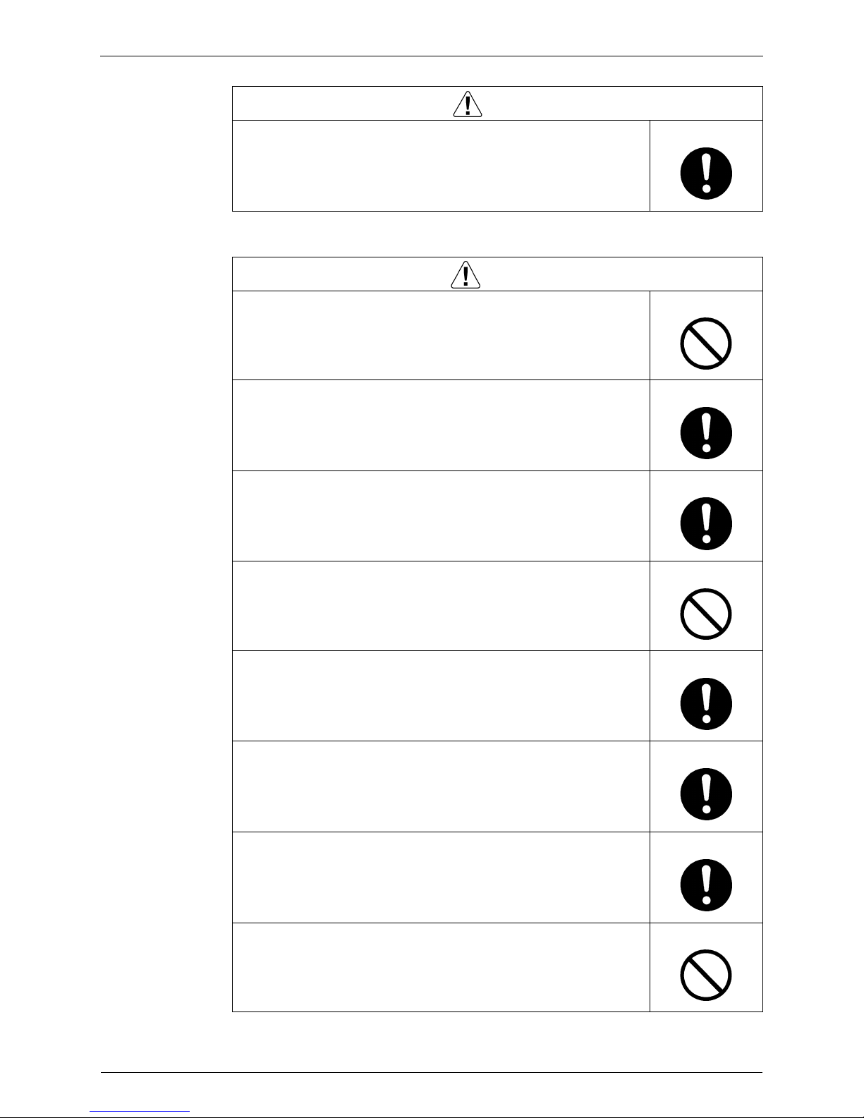
Use the welder in a well-ventilated place.
Using the welder in an enclosed room may cause oxygen deficiency.
Caution
Warning
Do not store the equipment in a room with successive fire sources (e.g.,
naked flame, gas appliance, electric heater).
Be sure to use parts listed in the service parts list of the applicable model
and appropriate tools to conduct repair work. Never attempt to modify the
equipment.
The use of inappropriate parts or tools may cause an electrical shock,
excessive heat generation or fire.
If the power cable and lead wires have scratches or deteriorated, be sure
to replace them.
Damaged cable and wires may cause an electrical shock, excessive heat
generation or fire.
Do not use a joined power cable or extension cable, or share the same
power outlet with other electrical appliances, since it may cause an
electrical shock, excessive heat generation or fire.
Be sure to use an exclusive power circuit for the equipment, and follow
the local technical standards related to the electrical equipment, the
internal wiring regulations, and the instruction manual for installation
when conducting electrical work.
Insufficient power circuit capacity and improper electrical work may cause an
electrical shock or fire.
Be sure to use the specified cable for wiring between the indoor and
outdoor units.
Make the connections securely and route the cable properly so that there is no
force pulling the cable at the connection terminals.
Improper connections may cause excessive heat generation or fire.
When wiring between the indoor and outdoor units, make sure that the
terminal cover does not lift off or dismount because of the cable.
If the cover is not mounted properly, the terminal connection section may cause
an electrical shock, excessive heat generation or fire.
Do not damage or modify the power cable.
Damaged or modified power cable may cause an electrical shock or fire.
Placing heavy items on the power cable, and heating or pulling the power cable
may damage the cable.
SiBE041011EC Safety Cautions
viii
Do not mix air or gas other than the specified refrigerant (R-32 / R-410A /
R-22) in the refrigerant system.
If air enters the refrigerating system, an excessively high pressure results,
causing equipment damage and injury.
If the refrigerant gas leaks, be sure to locate the leaking point and repair
it before charging the refrigerant. After charging refrigerant, make sure
that there is no refrigerant leak.
If the leaking point cannot be located and the repair work must be stopped, be
sure to perform pump-down and close the service valve, to prevent the
refrigerant gas from leaking into the room. The refrigerant gas itself is
harmless, but it may generate toxic gases when it contacts flames, such as fan
and other heaters, stoves and ranges.
When relocating the equipment, make sure that the new installation site
has sufficient strength to withstand the weight of the equipment.
If the installation site does not have sufficient strength and if the installation
work is not conducted securely, the equipment may fall and cause injury.
Check to make sure that the power cable plug is not dirty or loose, then
insert the plug into a power outlet securely.
If the plug has dust or loose connection, it may cause an electrical shock or fire.
Be sure to install the product correctly by using the provided standard
installation frame.
Incorrect use of the installation frame and improper installation may cause the
equipment to fall, resulting in injury.
For unitary type
only
Be sure to install the product securely in the installation frame mounted
on the window frame.
If the unit is not securely mounted, it may fall and cause injury.
For unitary type
only
When replacing the coin battery in the remote controller, be sure to
dispose of the old battery to prevent children from swallowing it.
If a child swallows the coin battery, see a doctor immediately.
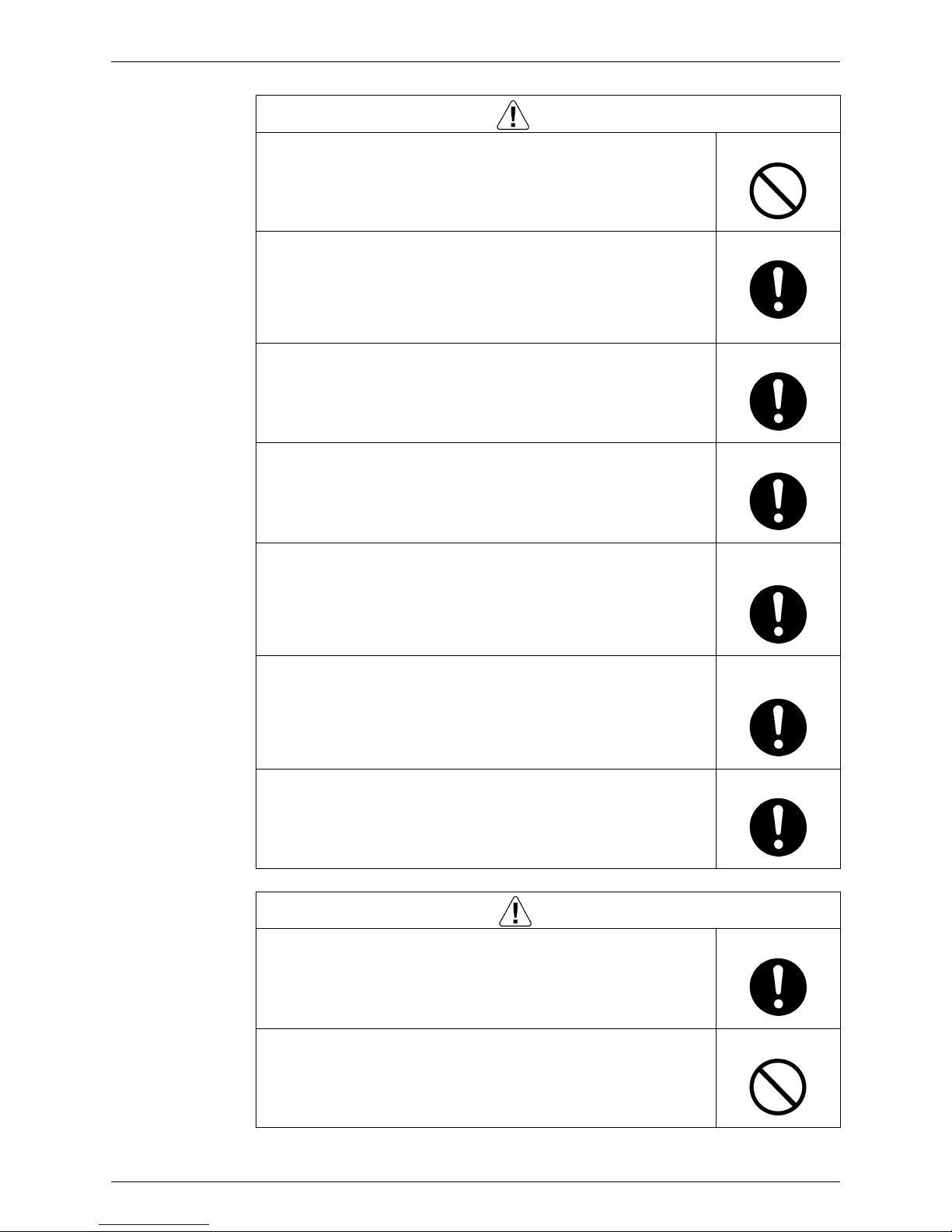
Warning
Caution
Installation of a leakage breaker is necessary in some cases depending
on the conditions of the installation site, to prevent electrical shocks.
Do not install the equipment in a place where there is a possibility of
combustible gas leaks.
If the combustible gas leaks and remains around the unit, it may cause a fire.

Safety Cautions SiBE041011EC
ix
Check to see if the parts and wires are mounted and connected properly,
and if the connections at the soldered or crimped terminals are secure.
Improper installation and connections may cause excessive heat generation,
fire or an electrical shock.
If the installation platform or frame has corroded, replace it.
Corroded installation platform or frame may cause the unit to fall, resulting in
injury.
Check the grounding, and repair it if the equipment is not properly
grounded.
Improper grounding may cause an electrical shock.
Be sure to measure the insulation resistance after the repair, and make
sure that the resistance is 1 MΩ or higher.
Faulty insulation may cause an electrical shock.
Be sure to check the drainage of the indoor unit after the repair.
Faulty drainage may cause the water to enter the room and wet the furniture
and floor.
Do not tilt the unit when removing it.
The water inside the unit may spill and wet the furniture and floor.
Be sure to install the packing and seal on the installation frame properly.
If the packing and seal are not installed properly, water may enter the room and
wet the furniture and floor.
For unitary type
only
Caution

SiBE041011EC Used Icons
x
2. Used Icons
The following icons are used to attract the attention of the reader to specific information.
Icon Type of
Information
Description
Warning
Warning A Warning is used when there is danger of personal injury.
Caution
Caution A Caution is used when there is danger that the reader, through
incorrect manipulation, may damage equipment, lose data, get
an unexpected result or has to restart (part of) a procedure.
Note:
Note A Note provides information that is not indispensable, but may
nevertheless be valuable to the reader, such as tips and tricks.
Reference A Reference guides the reader to other places in this binder or
in this manual, where he/she will find additional information on a
specific topic.

SiBE041011EC
1 List of Functions
Part 1
List of Functions
1. Functions.................................................................................................2
1.1 Cooling Only.............................................................................................2
1.2 Heat Pump ...............................................................................................3
SiBE041011EC Functions
List of Functions 2
1. Functions
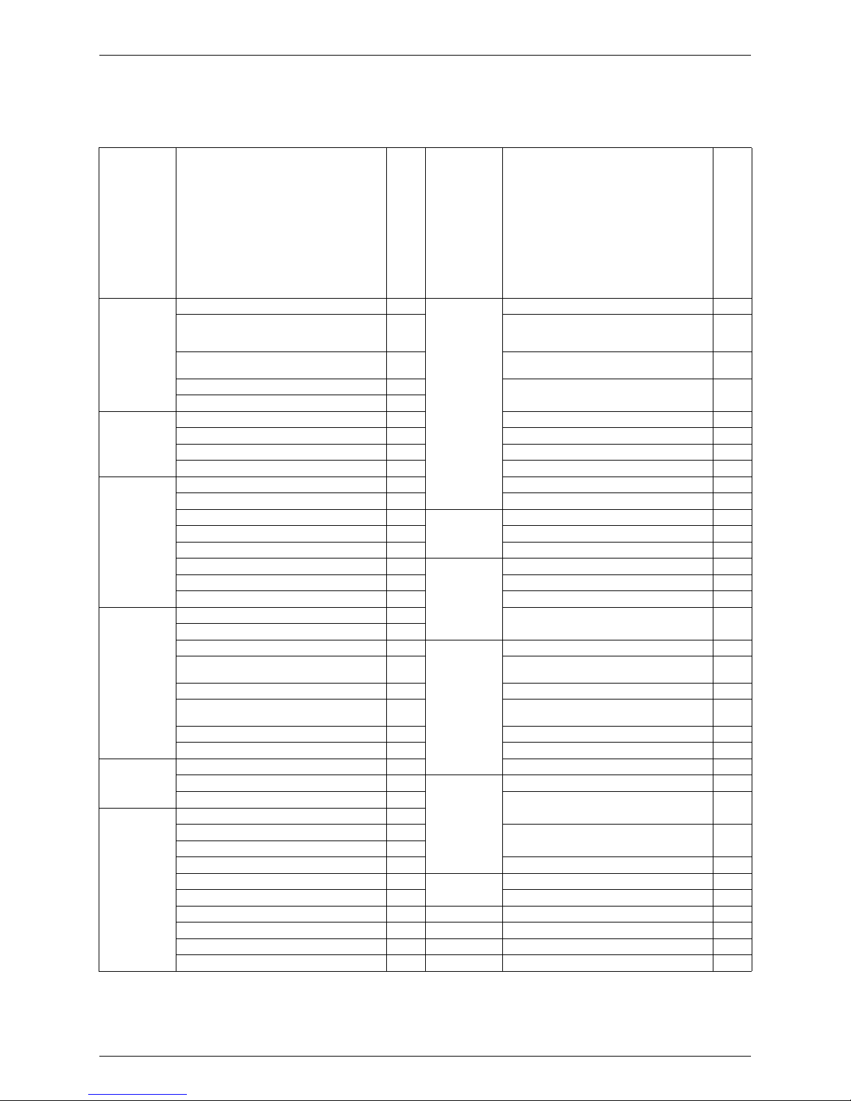
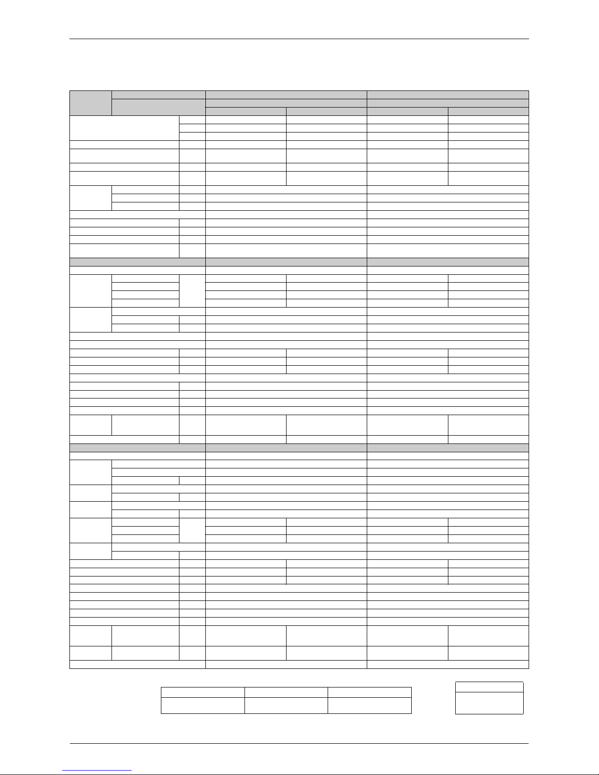
1.1 Cooling Only
Category Functions
FTXS60/71GV1B
RKS60F3V1B, RKS60F3V1B9
RKS71FAV1B
Category Functions
FTXS60/71GV1B
RKS60F3V1B, RKS60F3V1B9
RKS71FAV1B
Basic Function Inverter (with inverter power control)
z
Health & Clean Air-purifying filter —
Operation limit for cooling (°CDB)
–10
~46
Photocatalytic deodorizing filter —
Operation limit for heating (°CWB) —
Air-purifying filter with photocatalytic
deodorizing function
—
PAM control
z
Titanium apatite photocatalytic air-purifying
filter
z
Standby electricity saving —
Compressor Oval scroll compressor — Air filter (prefilter)
z
Swing compressor
z
Wipe-clean flat panel
z
Rotary compressor — Washable grille —
Reluctance DC motor
z
MOLD PROOF operation —
Comfortable
Airflow
Power-airflow flap — Heating dry operation —
Power-airflow dual flaps
z
Good-sleep cooling operation —
Power-airflow diffuser — Timer WEEKLY TIMER operation
z
Wide-angle louvers
z
24-hour ON/OFF TIMER
z
Auto-swing (up and down)
z
NIGHT SET mode
z
Auto-swing (right and left)
z
Worry Free
(Reliability &
Durability)
Auto-restart (after power failure)
z
3-D airflow
z
Self-diagnosis (R/C, LED)
z
COMFORT AIRFLOW operation
z
Wiring error check function —
Comfort
Control
Auto fan speed
z
Anti-corrosion treatment of outdoor heat
exchanger
z
Indoor unit quiet operation
z
NIGHT QUIET mode (automatic) — Flexibility Multi-split / split type compatible indoor unit
z
OUTDOOR UNIT QUIET operation
(manual)
z
H/P, C/O compatible indoor unit
z
INTELLIGENT EYE operation
z
Flexible power supply correspondence —
Quick warming function
(preheating control)
— High ceiling application —
Hot-start function — Chargeless 10 m
Automatic defrosting — Either side drain (right or left)
z
Operation Automatic operation — Power selection —
Program dry operation
z
Remote
Control
5-room centralized controller (option)
z
Fan only
z
Remote control adaptor
(normal open pulse contact) (option)
z
Lifestyle
Convenience
New POWERFUL operation (non-inverter) —
Inverter POWERFUL operation
z
Remote control adaptor
(normal open contact) (option)
z
Priority-room setting —
COOL / HEAT mode lock — DIII-NET compatible (adaptor) (option)
z
HOME LEAVE operation — Remote
Controller
Wireless
z
ECONO operation
z
Wired (option)
z
Indoor unit ON/OFF button
z
Signal receiving sign
z
R/C with back light —
Temperature display —
Note:
z : Available
— : Not available
: Lower limit can be extended by turning switch or
cutting jumper. (facility use only)
Refer to page 115 for detail.
Functions SiBE041011EC
3 List of Functions
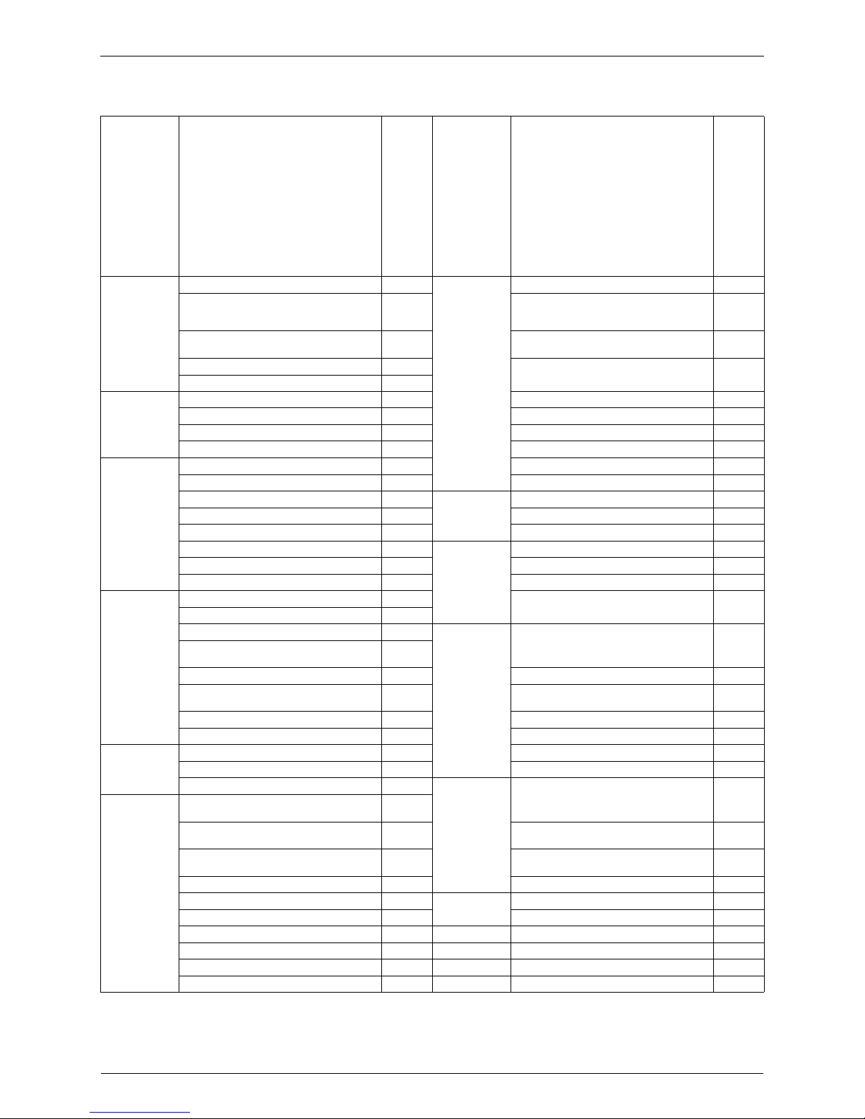
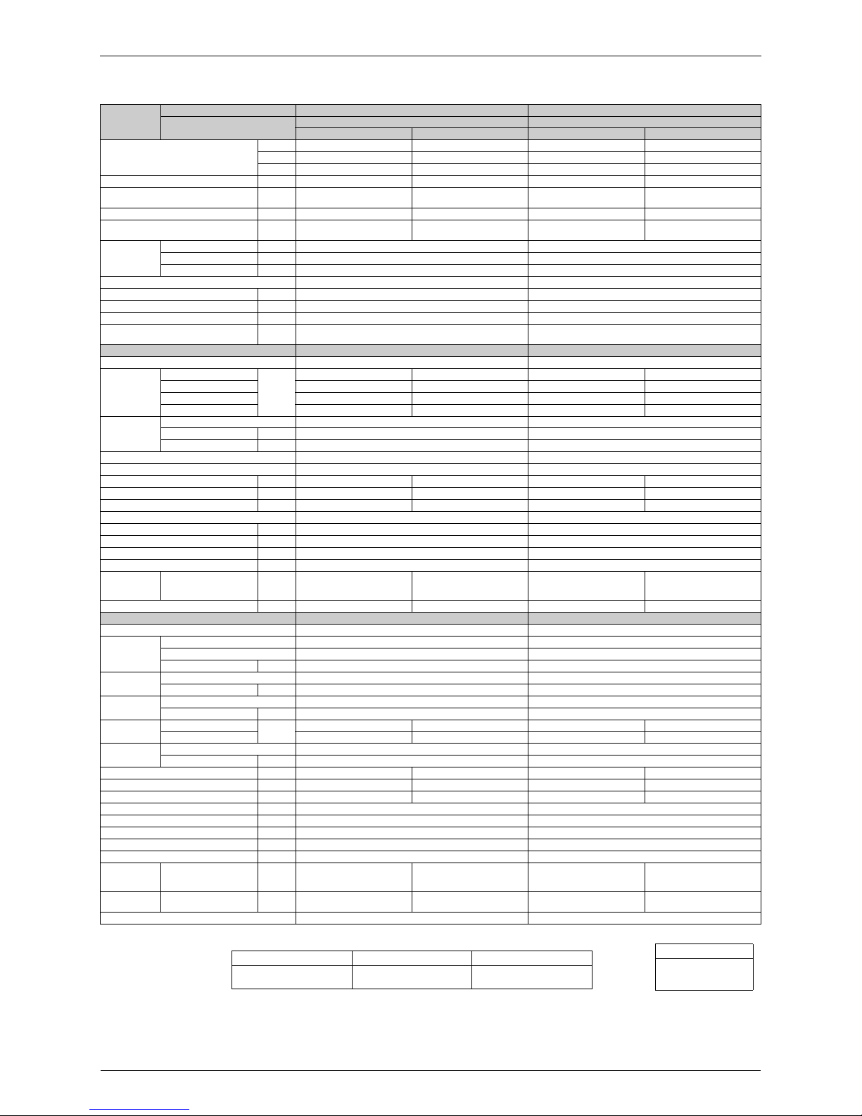
1.2 Heat Pump
Category Functions
FTXS60/71GV1B
RXS60F3V1B, RXS60F3V1B9
RXS60F4V1B, RXS71FAV1B
RXS71FAV1B9, RXS71FAV1B8
Category Functions
FTXS60/71GV1B
RXS60F3V1B, RXS60F3V1B9
RXS60F4V1B, RXS71FAV1B
RXS71FAV1B9, RXS71FAV1B8
Basic Function Inverter (with inverter power control)
z
Health & Clean Air-purifying filter —
Operation limit for cooling (°CDB)
–10
~46
Photocatalytic deodorizing filter —
Operation limit for heating (°CWB)
–15
~18
Air-purifying filter with photocatalytic
deodorizing function
—
PAM control
z
Titanium apatite photocatalytic
air-purifying filter
z
Standby electricity saving —
Compressor Oval scroll compressor — Air filter (prefilter)
z
Swing compressor
z
Wipe-clean flat panel
z
Rotary compressor — Washable grille —
Reluctance DC motor
z
MOLD PROOF operation —
Comfortable
Airflow
Power-airflow flap — Heating dry operation —
Power-airflow dual flaps
z
Good-sleep cooling operation —
Power-airflow diffuser — Timer WEEKLY TIMER operation
z
Wide-angle louvers
z
24-hour ON/OFF TIMER
z
Auto-swing (up and down)
z
NIGHT SET mode
z
Auto-swing (right and left)
z
Worry Free
(Reliability &
Durability)
Auto-restart (after power failure)
z
3-D airflow
z
Self-diagnosis (R/C, LED)
z
COMFORT AIRFLOW operation
z
Wiring error check function —
Comfort
Control
Auto fan speed
z
Anti-corrosion treatment of outdoor heat
exchanger
z
Indoor unit quiet operation
z
NIGHT QUIET mode (automatic) — Flexibility
Multi-split / split type compatible indoor
unit
z
OUTDOOR UNIT QUIET operation
(manual)
z
INTELLIGENT EYE operation
z
H/P, C/O compatible indoor unit
z
Quick warming function
(preheating control)
z
Flexible power supply correspondence —
Hot-start function
z
High ceiling application —
Automatic defrosting
z
Chargeless 10 m
Operation Automatic operation
z
Either side drain (right or left)
z
Program dry operation
z
Power selection —
Fan only
z
Remote
Control
5-room centralized controller (option)
z
Lifestyle
Convenience
New POWERFUL operation
(non-inverter)
—
Inverter POWERFUL operation
z
Remote control adaptor
(normal open pulse contact) (option)
z
Priority-room setting —
Remote control adaptor
(normal open contact) (option)
z
COOL / HEAT mode lock —
DIII-NET compatible (adaptor) (option)
z
HOME LEAVE operation — Remote
Controller
Wireless
z
ECONO operation
z
Wired (option)
z
Indoor unit ON/OFF button
z
Signal receiving sign
z
R/C with back light —
Temperature display —
Note:
z : Available
— : Not available
: Lower limit can be extended by turning switch or
cutting jumper. (facility use only)
Refer to page 115 for detail.

SiBE041011EC
Specifications 4
Part 2
Specifications
1. Specifications..........................................................................................5
1.1 Cooling Only.............................................................................................5
1.2 Heat Pump ...............................................................................................7
Specifications SiBE041011EC
5 Specifications
1. Specifications
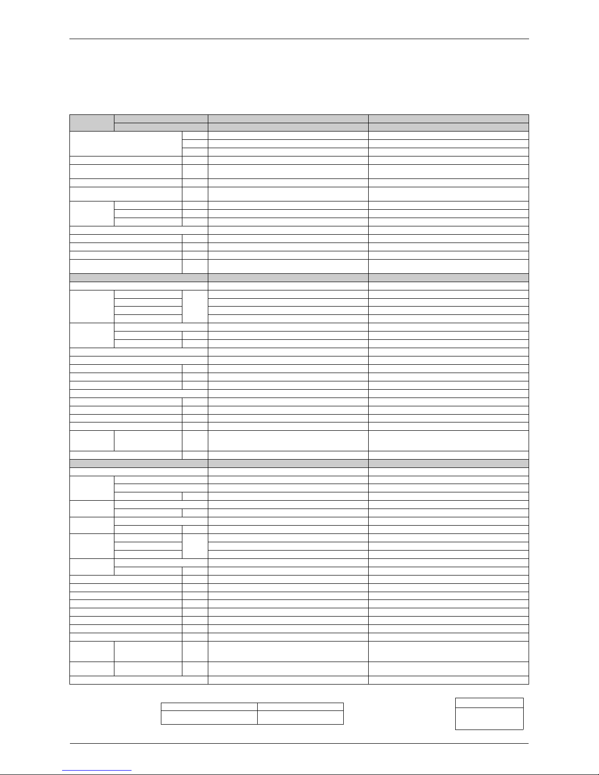
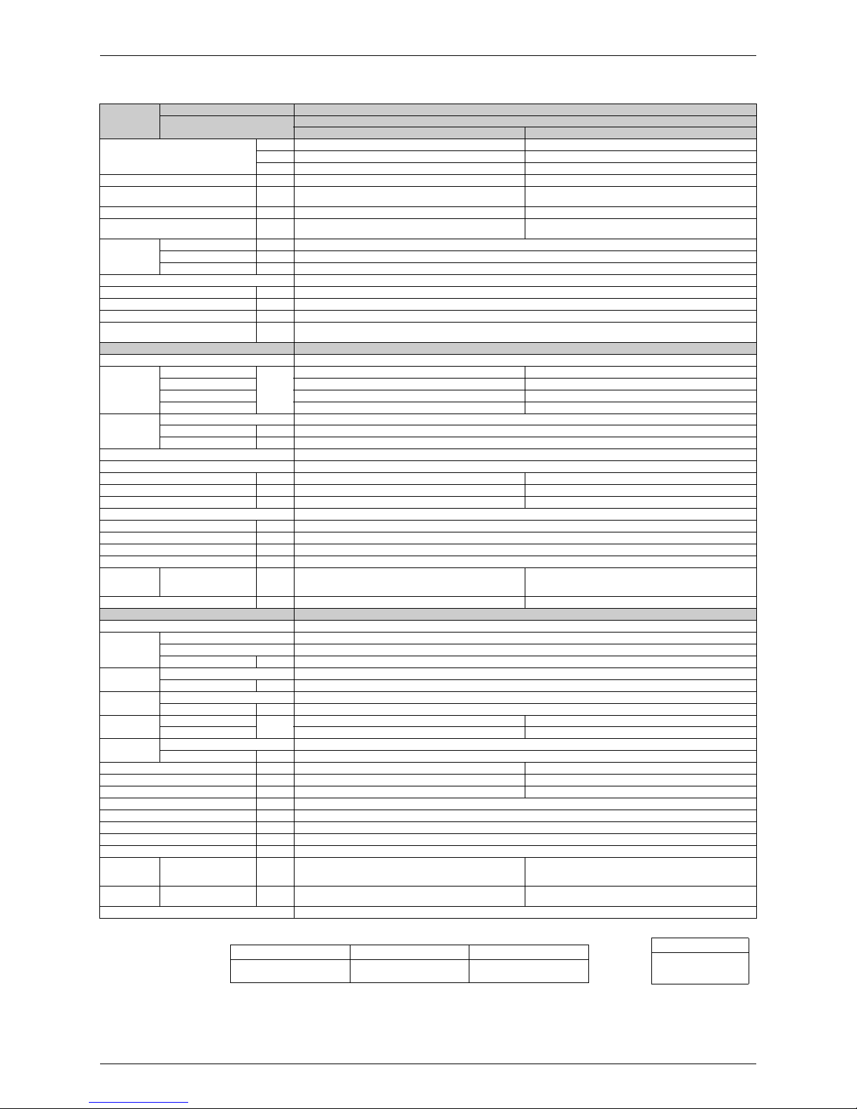
1.1 Cooling Only
50 Hz, 220 - 230 - 240 V
Note:
The data are based on the conditions shown in the table below.
Model
Indoor Unit FTXS60GV1B FTXS71GV1B
Outdoor Unit RKS60F3V1B RKS71FAV1B
Capacity Rated
(Min. ~ Max.)
kW 6.0 (1.7 ~ 6.7) 7.1 (2.3 ~ 8.5)
Btu/h 20,500 (5,800 ~ 22,900) 24,200 (7,800 ~ 29,000)
kcal/h 5,160 (1,460 ~ 5,760) 6,110 (1,980 ~ 7,310)
Running Current (Rated) A 9.2 - 8.8 - 8.4 10.8 - 10.4 - 9.9
Power Consumption Rated
(Min. ~ Max.)
W 1,990 (440 ~ 2,400) 2,350 (570 ~ 3,200)
Power Factor % 98.3 - 98.3 - 98.7 98.9 - 98.2 - 98.9
EER (Cooling) Rated
(Min. ~ Max.)
W/W 3.02 (3.86 ~ 2.79) 3.02 (4.04 ~ 2.66)
Piping
Connections
Liquid mm φ 6.4 φ 6.4
Gas mm φ 12.7 φ 15.9
Drain mm φ 18.0 φ 18.0
Heat Insulation Both Liquid and Gas Pipes Both Liquid and Gas Pipes
Max. lnterunit Piping Length m 30 30
Max. lnterunit Height Difference m 20 20
Chargeless m 10 10
Amount of Additional Charge of
Refrigerant
g/m 20 20
Indoor Unit FTXS60GV1B FTXS71GV1B
Front Panel Color White White
Airflow Rate
H
m³/min
(cfm)
16.0 (565) 17.2 (607)
M 13.5 (477) 14.5 (512)
L 11.3 (399) 11.5 (406)
SL 10.1 (357) 10.5 (371)
Fan
Type Cross Flow Fan Cross Flow Fan
Motor Output W 43 43
Speed Steps 5 Steps, Quiet, Auto 5 Steps, Quiet, Auto
Air Direction Control Right, Left, Horizontal, Downward Right, Left, Horizontal, Downward
Air Filter Removable / Washable / Mildew Proof Removable / Washable / Mildew Proof
Running Current (Rated) A 0.19 - 0.18 - 0.17 0.21 - 0.20 - 0.19
Power Consumption (Rated) W 40 - 40 - 40 45 - 45 - 45
Power Factor % 95.7 - 96.6 - 98.0 97.4 - 97.8 - 98.7
Temperature Control Microcomputer Control Microcomputer Control
Dimensions (H × W × D) mm 290 × 1,050 × 250 290 × 1,050 × 250
Packaged Dimensions (H × W × D) mm 361 × 1,145 × 364 361 × 1,145 × 364
Weight (Mass) kg 12 12
Gross Weight (Gross Mass) kg 18 18
Sound
Pressure
Level
H / M / L / SL dB(A) 45 / 41 / 36 / 33 46 / 42 / 37 / 34
Sound Power Level dB 61 62
Outdoor Unit RKS60F3V1B RKS71FAV1B
Casing Color Ivory White Ivory White
Compressor
Type Hermetically Sealed Swing Type Hermetically Sealed Swing Type
Model 2YC36BXD 2YC63BXD
Motor Output W 1,100 1,920
Refrigerant Oil
Type FVC50K FVC50K
Charge L 0.65 0.75
Refrigerant
Type R-410A R-410A
Charge kg 1.5 2.3
Airflow Rate
HH
m³/min
(cfm)
54.2 (1,914) 57.1 (2,016)
H 50.9 (1,797) 54.5 (1,924)
SL 42.4 (1,497) 46.0 (1,624)
Fan
Type Propeller Propeller
Motor Output W 53 66
Running Current (Rated) A 9.01 - 8.62 - 8.23 10.59 - 10.20 - 9.71
Power Consumption (Rated) W 1,950 - 1,950 - 1,950 2,305 - 2,305 - 2,305
Power Factor % 98.4 - 98.4 - 98.7 98.9 - 98.3 - 98.9
Starting Current A 9.2 10.8
Dimensions (H × W × D) mm 735 × 825 × 300 770 × 900 × 320
Packaged Dimensions (H × W × D) mm 797 × 992 × 390 900 × 925 × 390
Weight (Mass) kg 47 71
Gross Weight (Gross Mass) kg 52 79
Sound
Pressure
Level
H / SL dB(A) 49 / 46 52 / 49
Sound Power
Level
HdB 63 66
Drawing No. C: 3D065735A 3D065737A
Conversion Formulae
kcal/h = kW × 860
Btu/h = kW × 3412
cfm = m³/min × 35.3
Cooling Piping Length
Indoor ; 27°CDB / 19°CWB
Outdoor ; 35°CDB / 24°CWB
5 m
SiBE041011EC Specifications
Specifications 6
50 Hz, 220 - 230 - 240 V
Note:
The data are based on the conditions shown in the table below.
Model
Indoor Unit FTXS60GV1B
Outdoor Unit RKS60F3V1B9
Capacity Rated
(Min. ~ Max.)
kW 6.0 (1.7 ~ 6.7)
Btu/h 20,500 (5,800 ~ 22,900)
kcal/h 5,160 (1,460 ~ 5,760)
Running Current (Rated) A 9.2 - 8.8 - 8.4
Power Consumption Rated
(Min. ~ Max.)
W 1,990 (440 ~ 2,400)
Power Factor % 98.3 - 98.3 - 98.7
EER (Cooling) Rated
(Min. ~ Max.)
W/W 3.02 (3.86 ~ 2.79)
Piping
Connections
Liquid mm φ 6.4
Gas mm φ 12.7
Drain mm φ 18.0
Heat Insulation Both Liquid and Gas Pipes
Max. lnterunit Piping Length m 30
Max. lnterunit Height Difference m 20
Chargeless m 10
Amount of Additional Charge of
Refrigerant
g/m 20
Indoor Unit FTXS60GV1B
Front Panel Color Whit e
Airflow Rate
H
m³/min
(cfm)
16.0 (565)
M 13.5 (477)
L 11.3 (399)
SL 10.1 (357)
Fan
Type Cross Flow Fan
Motor Output W 43
Speed Steps 5 Steps, Quiet, Auto
Air Direction Control Right, Left, Horizontal, Downward
Air Filter Removable / Washable / Mildew Proof
Running Current (Rated) A 0.19 - 0.18 - 0.17
Power Consumption (Rated) W 40 - 40 - 40
Power Factor % 95.7 - 96.6 - 98.0
Temperature Control Microcomputer Control
Dimensions (H × W × D) mm 290 × 1,050 × 250
Packaged Dimensions (H × W × D) mm 361 × 1,145 × 364
Weight (Mass) kg 12
Gross Weight (Gross Mass) kg 18
Sound
Pressure
Level
H / M / L / SL dB(A) 45 / 41 / 36 / 33
Sound Power Level dB 61
Outdoor Unit RKS60F3V1B9
Casing Color Ivory White
Compressor
Type Hermetically Sealed Swing Type
Model 2YC36BXD
Motor Output W 1,100
Refrigerant Oil
Type FVC50K
Charge L 0.65
Refrigerant
Type R-410A
Charge kg 1.5
Airflow Rate
HH
m³/min
(cfm)
54.2 (1,914)
H 50.9 (1,797)
SL 42.4 (1,497)
Fan
Type Propeller
Motor Output W 53
Running Current (Rated) A 9.01 - 8.62 - 8.23
Power Consumption (Rated) W 1,950 - 1,950 - 1,950
Power Factor % 98.4 - 98.4 - 98.7
Starting Current A 9.2
Dimensions (H × W × D) mm 735 × 825 × 300
Packaged Dimensions (H × W × D) mm 797 × 992 × 390
Weight (Mass) kg 46
Gross Weight (Gross Mass) kg 51
Sound
Pressure
Level
H / SL dB(A) 49 / 46
Sound Power
Level
HdB 63
Drawing No. C: 3D065735A
Conversion Formulae
kcal/h = kW × 860
Btu/h = kW × 3412
cfm = m³/min × 35.3
Cooling Piping Length
Indoor ; 27°CDB / 19°CWB
Outdoor ; 35°CDB / 24°CWB
5 m
Specifications SiBE041011EC
7 Specifications
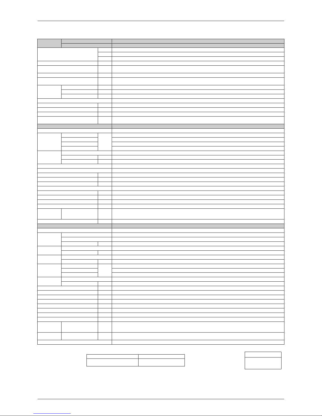
1.2 Heat Pump
50 Hz, 220 - 230 - 240 V
Note:
The data are based on the conditions shown in the table below.
Model
Indoor Unit FTXS60GV1B FTXS71GV1B
Outdoor Unit
RXS60F3V1B RXS71FAV1B
Cooling Heating Cooling Heating
Capacity Rated
(Min. ~ Max.)
kW 6.0 (1.7 ~ 6.7) 7.0 (1.7 ~ 8.0) 7.1 (2.3 ~ 8.5) 8.2 (2.3 ~ 10.2)
Btu/h 20,500 (5,800 ~ 22,900) 23,900 (5,800 ~ 27,300) 24,200 (7,800 ~ 29,000) 28,000 (7,800 ~ 34,800)
kcal/h 5,160 (1,460 ~ 5,760) 6,020 (1,460 ~ 6,880) 6,110 (1,980 ~ 7,310) 7,050 (1,980 ~ 8,770)
Running Current (Rated) A 9.2 - 8.8 - 8.4 9.4 - 9.0 - 8.6 10.8 - 10.4 - 9.9 11.7 - 11.2 - 10.7
Power Consumption Rated
(Min. ~ Max.)
W 1,990 (440 ~ 2,400) 2,040 (400 ~ 2,810) 2,350 (570 ~ 3,200) 2,550 (520 ~ 3,820)
Power Factor % 98.3 - 98.3 - 98.7 98.6 - 98.6 - 98.8 98.9 - 98.2 - 98.9 99.1 - 99.0 - 99.3
EER (Cooling) / COP (Heating)
Rated (Min. ~ Max.)
W/W 3.02 (3.86 ~ 2.79) 3.43 (4.25 ~ 2.85) 3.02 (4.04 ~ 2.66) 3.22 (4.42 ~ 2.67)
Piping
Connections
Liquid mm φ 6.4 φ 6.4
Gas mm φ 12.7 φ 15.9
Drain mm φ 18.0 φ 18.0
Heat Insulation Both Liquid and Gas Pipes Both Liquid and Gas Pipes
Max. Interunit Piping Length m 30 30
Max. Interunit Height Difference m 20 20
Chargeless m 10 10
Amount of Additional Charge of
Refrigerant
g/m 20 20
Indoor Unit FTXS60GV1B FTXS71GV1B
Front Panel Color White White
Airflow Rate
H
m³/min
(cfm)
16.0 (565) 17.2 (607) 17.2 (607) 19.5 (689)
M 13.5 (477) 14.9 (526) 14.5 (512) 16.7 (590)
L 11.3 (399) 12.6 (445) 11.5 (406) 14.2 (501)
SL 10.1 (357) 11.3 (399) 10.5 (371) 12.6 (445)
Fan
Type Cross Flow Fan Cross Flow Fan
Motor Output W 43 43
Speed Steps 5 Steps, Quiet, Auto 5 Steps, Quiet, Auto
Air Direction Control Right, Left, Horizontal, Downward Right, Left, Horizontal, Downward
Air Filter Removable / Washable / Mildew Proof Removable / Washable / Mildew Proof
Running Current (Rated) A 0.19 - 0.18 - 0.17 0.21 - 0.20 - 0.19 0.21 - 0.20 - 0.19 0.28 - 0.27 - 0.26
Power Consumption (Rated) W 40 - 40 - 40 45 - 45 - 45 45 - 45 - 45 60 - 60 - 60
Power Factor % 95.7 - 96.6 - 98.0 97.4 - 97.8 - 98.7 97.4 - 97.8 - 98.7 97.4 - 96.6 - 96.2
Temperature Control Microcomputer Control Microcomputer Control
Dimensions (H × W × D) mm 290 × 1,050 × 250 290 × 1,050 × 250
Packaged Dimensions (H × W × D) mm 361 × 1,145 × 364 361 × 1,145 × 364
Weight (Mass) kg 12 12
Gross Weight (Gross Mass) kg 18 18
Sound
Pressure
Level
H / M / L / SL dB(A) 45 / 41 / 36 / 33 44 / 40 / 35 / 32 46 / 42 / 37 / 34 46 / 42 / 37 / 34
Sound Power Level dB 61 60 62 62
Outdoor Unit RXS60F3V1B RXS71FAV1B
Casing Color Ivory White Ivory White
Compressor
Type Hermetically Sealed Swing Type Hermetically Sealed Swing Type
Model 2YC36BXD 2YC63BXD
Motor Output W 1, 100 1,920
Refrigerant
Oil
Type FVC50K FVC50K
Charge L 0.65 0.75
Refrigerant
Type R-410A R-410A
Charge kg 1.5 2.3
Airflow Rate
HH
m³/min
(cfm)
54.2 (1,914) — 57.1 (2,016) —
H 50.9 (1,797) 46.3 (1,635) 54.5 (1,924) 46.0 (1,624)
SL 42.4 (1,497) 42.4 (1,497) 46.0 (1,624) 46.0 (1,624)
Fan
Type Propeller Propeller
Motor Output W 53 66
Running Current (Rated) A 9.01 - 8.62 - 8.23 9.19 - 8.80 - 8.41 10.59 - 10.20 - 9.71 11.42 - 10.93 - 10.44
Power Consumption (Rated) W 1,950 - 1,950 - 1,950 1,995 - 1,995 - 1,995 2,305 - 2,305 - 2,305 2,490 - 2,490 - 2,490
Power Factor % 98.4 - 98.4 - 98.7 98.7 - 98.6 - 98.8 98.9 - 98.3 - 98.9 99.1 - 99.0 - 99.4
Starting Current A 9.4 11.7
Dimensions (H × W × D) mm 735 × 825 × 300 770 × 900 × 320
Packaged Dimensions (H × W × D) mm 797 × 992 × 390 900 × 925 × 390
Weight (Mass) kg 48 71
Gross Weight (Gross Mass) kg 53 79
Sound
Pressure
Level
H / SL dB(A) 49 / 46 49 / 46 52 / 49 52 / 49
Sound Power
Level
HdB63636666
Drawing No. C: 3D065512A 3D065513A
Conversion Formulae
kcal/h = kW × 860
Btu/h = kW × 3412
cfm = m³/min × 35.3
Cooling Heating Piping Length
Indoor ; 27°CDB / 19°CWB
Outdoor ; 35°CDB / 24°CWB
Indoor ; 20°CDB
Outdoor ; 7°CDB / 6°CWB
5 m

SiBE041011EC Specifications
Specifications 8
50 Hz, 220 - 230 - 240 V
Note:
The data are based on the conditions shown in the table below.
Model
Indoor Unit FTXS60GV1B
Outdoor Unit
RXS60F3V1B9
Cooling Heating
Capacity Rated
(Min. ~ Max.)
kW 6.0 (1.7 ~ 6.7) 7.0 (1.7 ~ 8.0)
Btu/h 20,500 (5,800 ~ 22,900) 23,900 (5,800 ~ 27,300)
kcal/h 5,160 (1,460 ~ 5,760) 6,020 (1,460 ~ 6,880)
Running Current (Rated) A 9.2 - 8.8 - 8.4 9.4 - 9.0 - 8.6
Power Consumption Rated
(Min. ~ Max.)
W 1,990 (440 ~ 2,400) 2,040 (400 ~ 2,810)
Power Factor % 98.3 - 98.3 - 98.7 98.6 - 98.6 - 98.8
EER (Cooling) / COP (Heating)
Rated (Min. ~ Max.)
W/W 3.02 (3.86 ~ 2.79) 3.43 (4.25 ~ 2.85)
Piping
Connections
Liquid mm φ 6.4
Gas mm φ 12.7
Drain mm φ 18.0
Heat Insulation Both Liquid and Gas Pipes
Max. Interunit Piping Length m 30
Max. Interunit Height Difference m 20
Chargeless m 10
Amount of Additional Charge of
Refrigerant
g/m 20
Indoor Unit FTXS60GV1B
Front Panel Color Whit e
Airflow Rate
H
m³/min
(cfm)
16.0 (565) 17.2 (607)
M 13.5 (477) 14.9 (526)
L 11.3 (399) 12.6 (445)
SL 10.1 (357) 11.3 (399)
Fan
Type Cross Flow Fan
Motor Output W 43
Speed Steps 5 Steps, Quiet, Auto
Air Direction Control Right, Left, Horizontal, Downward
Air Filter Removable / Washable / Mildew Proof
Running Current (Rated) A 0.19 - 0.18 - 0.17 0.21 - 0.20 - 0.19
Power Consumption (Rated) W 40 - 40 - 40 45 - 45 - 45
Power Factor % 95.7 - 96.6 - 98.0 97.4 - 97.8 - 98.7
Temperature Control Microcomputer Control
Dimensions (H × W × D) mm 290 × 1,050 × 250
Packaged Dimensions (H × W × D) mm 361 × 1,145 × 364
Weight (Mass) kg 12
Gross Weight (Gross Mass) kg 18
Sound
Pressure
Level
H / M / L / SL dB(A) 45 / 41 / 36 / 33 44 / 40 / 35 / 32
Sound Power Level dB 60 59
Outdoor Unit RXS60F3V1B9
Casing Color Ivory White
Compressor
Type Hermetical ly Sealed Swing Type
Model 2YC36BXD
Motor Output W 1,100
Refrigerant
Oil
Type FVC50K
Charge L 0.65
Refrigerant
Type R-410A
Charge kg 1.5
Airflow Rate
H
m³/min
(cfm)
50.9 (1,797) 46.3 (1,635)
SL 42.4 (1,497) 42.4 (1,497)
Fan
Type Propeller
Motor Output W 53
Running Current (Rated) A 9.01 - 8.62 - 8.23 9.19 - 8.80 - 8.41
Power Consumption (Rated) W 1,950 - 1,950 - 1,950 1,995 - 1,995 - 1,995
Power Factor % 98.4 - 98.4 - 98.7 98.7 - 98.6 - 98.8
Starting Current A 9.4
Dimensions (H × W × D) mm 735 × 825 × 300
Packaged Dimensions (H × W × D) mm 797 × 992 × 390
Weight (Mass) kg 47
Gross Weight (Gross Mass) kg 52
Sound
Pressure
Level
H / SL dB(A) 49 / 46 49 / 46
Sound Power
Level
HdB 63 63
Drawing No. C: 3D080641
Conversion Formulae
kcal/h = kW × 860
Btu/h = kW × 3412
cfm = m³/min × 35.3
Cooling Heating Piping Length
Indoor ; 27°CDB / 19°CWB
Outdoor ; 35°CDB / 24°CWB
Indoor ; 20°CDB
Outdoor ; 7°CDB / 6°CWB
5 m
Specifications SiBE041011EC
9 Specifications
50 Hz, 220 - 230 - 240 V
Note:
The data are based on the conditions shown in the table below.
Model
Indoor Unit FTXS60GV1B FTXS71GV1B
Outdoor Unit
RXS60F4V1B RXS71FAV1B9
Cooling Heating Cooling Heating
Capacity Rated
(Min. ~ Max.)
kW 6.0 (1.7 ~ 6.7) 7.0 (1.7 ~ 8.0) 7.1 (2.3 ~ 8.5) 8.2 (2.3 ~ 10.2)
Btu/h 20,500 (5,800 ~ 22,900) 23,900 (5,800 ~ 27,300) 24,200 (7,800 ~ 29,000) 28,000 (7,800 ~ 34,800)
kcal/h 5,160 (1,460 ~ 5,760) 6,020 (1,460 ~ 6,880) 6,110 (1,980 ~ 7,310) 7,050 (1,980 ~ 8,770)
Running Current (Rated) A 9.2 - 8.8 - 8.4 9.4 - 9.0 - 8.6 10.8 - 10.4 - 9.9 11.7 - 11.2 - 10.7
Power Consumption Rated
(Min. ~ Max.)
W 1,990 (440 ~ 2,400) 2,040 (400 ~ 2,810) 2,350 (570 ~ 3,200) 2,550 (520 ~ 3,820)
Power Factor % 98.3 - 98.3 - 98.7 98.6 - 98.6 - 98.8 98.9 - 98.2 - 98.9 99.1 - 99.0 - 99.3
EER (Cooling) / COP (Heating)
Rated (Min. ~ Max.)
W/W 3.02 (3.86 ~ 2.79) 3.43 (4.25 ~ 2.85) 3.02 (4.04 ~ 2.66) 3.22 (4.42 ~ 2.67)
Piping
Connections
Liquid mm φ 6.4 φ 6.4
Gas mm φ 12.7 φ 15.9
Drain mm φ 18.0 φ 18.0
Heat Insulation Both Liquid and Gas Pipes Both Liquid and Gas Pipes
Max. Interunit Piping Length m 30 30
Max. Interunit Height Difference m 20 20
Chargeless m 10 10
Amount of Additional Charge of
Refrigerant
g/m 20 20
Indoor Unit FTXS60GV1B FTXS71GV1B
Front Panel Color White White
Airflow Rate
H
m³/min
(cfm)
16.0 (565) 17.2 (607) 17.2 (607) 19.5 (689)
M 13.5 (477) 14.9 (526) 14.5 (512) 16.7 (590)
L 11.3 (399) 12.6 (445) 11.5 (406) 14.2 (501)
SL 10.1 (357) 11.3 (399) 10.1 (357) 12.6 (445)
Fan
Type Cross Flow Fan Cross Flow Fan
Motor Output W 43 43
Speed Steps 5 Steps, Quiet, Auto 5 Steps, Quiet, Auto
Air Direction Control Right, Left, Horizontal, Downward Right, Left, Horizontal, Downward
Air Filter Removable / Washable / Mildew Proof Removable / Washable / Mildew Proof
Running Current (Rated) A 0.19 - 0.18 - 0.17 0.21 - 0.20 - 0.19 0.21 - 0.20 - 0.19 0.28 - 0.27 - 0.26
Power Consumption (Rated) W 40 - 40 - 40 45 - 45 - 45 45 - 45 - 45 60 - 60 - 60
Power Factor % 95.7 - 96.6 - 98.0 97.4 - 97.8 - 98.7 97.4 - 97.8 - 98.7 97.4 - 96.6 - 96.2
Temperature Control Microcomputer Control Microcomputer Control
Dimensions (H × W × D) mm 290 × 1,050 × 250 290 × 1,050 × 250
Packaged Dimensions (H × W × D) mm 361 × 1,145 × 364 361 × 1,145 × 364
Weight (Mass) kg 12 12
Gross Weight (Gross Mass) kg 18 18
Sound
Pressure
Level
H / M / L / SL dB(A) 45 / 41 / 36 / 33 44 / 40 / 35 / 32 46 / 42 / 37 / 34 46 / 42 / 37 / 34
Sound Power Level dB 60 59 63 62
Outdoor Unit RXS60F4V1B RXS71FAV1B9
Casing Color Ivory White Ivory White
Compressor
Type Hermetically Sealed Swing Type Hermetically Sealed Swing Type
Model 2YC36BXD 2YC63BXD
Motor Output W 1, 100 1,920
Refrigerant
Oil
Type FVC50K FVC50K
Charge L 0.65 0.75
Refrigerant
Type R-410A R-410A
Charge kg 1.5 2.3
Airflow Rate
H
m³/min
(cfm)
50.9 (1,797) 46.3 (1,635) 54.5 (1,924) 46.0 (1,624)
SL 42.4 (1,497) 42.4 (1,497) 46.0 (1,624) 46.0 (1,624)
Fan
Type Propeller Propeller
Motor Output W 53 66
Running Current (Rated) A 9.01 - 8.62 - 8.23 9.19 - 8.80 - 8.41 10.59 - 10.20 - 9.71 11.42 - 10.93 - 10.44
Power Consumption (Rated) W 1,950 - 1,950 - 1,950 1,995 - 1,995 - 1,995 2,305 - 2,305 - 2,305 2,490 - 2,490 - 2,490
Power Factor % 98.4 - 98.4 - 98.7 98.7 - 98.6 - 98.8 98.9 - 98.3 - 98.9 99.1 - 99.0 - 99.4
Starting Current A 9.4 11.7
Dimensions (H × W × D) mm 735 × 825 × 300 770 × 900 × 320
Packaged Dimensions (H × W × D) mm 797 × 992 × 390 900 × 925 × 390
Weight (Mass) kg 47 71
Gross Weight (Gross Mass) kg 52 79
Sound
Pressure
Level
H / SL dB(A) 49 / 46 49 / 46 52 / 49 52 / 49
Sound Power
Level
HdB63636566
Drawing No. 3D080641 3D080176A
Conversion Formulae
kcal/h = kW × 860
Btu/h = kW × 3412
cfm = m³/min × 35.3
Cooling Heating Piping Length
Indoor ; 27°CDB / 19°CWB
Outdoor ; 35°CDB / 24°CWB
Indoor ; 20°CDB
Outdoor ; 7°CDB / 6°CWB
5 m
SiBE041011EC Specifications
Specifications 10
50 Hz, 220 - 230 - 240 V
Note:
The data are based on the conditions shown in the table below.
Model
Indoor Unit FTXS71GV1B
Outdoor Unit
RXS71FAV1B8
Cooling Heating
Capacity Rated
(Min. ~ Max.)
kW 7.1 (2.3 ~ 8.5) 8.2 (2.3 ~ 10.2)
Btu/h 24,200 (7,800 ~ 29,000) 28,000 (7,800 ~ 34,800)
kcal/h 6,110 (1,980 ~ 7,310) 7,050 (1,980 ~ 8,770)
Running Current (Rated) A 10.8 - 10.4 - 9.9 11.7 - 11.2 - 10.7
Power Consumption Rated
(Min. ~ Max.)
W 2,350 (570 ~ 3,200) 2,550 (520 ~ 3,820)
Power Factor % 98.9 - 98.2 - 98.9 99.1 - 99.0 - 99.3
EER (Cooling) / COP (Heating)
Rated (Min. ~ Max.)
W/W 3.02 (4.04 ~ 2.66) 3.22 (4.42 ~ 2.67)
Piping
Connections
Liquid mm φ 6.4
Gas mm φ 15.9
Drain mm φ 18.0
Heat Insulation Both Liquid and Gas Pipes
Max. Interunit Piping Length m 30
Max. Interunit Height Difference m 20
Chargeless m 10
Amount of Additional Charge of
Refrigerant
g/m 20
Indoor Unit FTXS71GV1B
Front Panel Color Whit e
Airflow Rate
H
m³/min
(cfm)
17.2 (607) 19.5 (689)
M 14.5 (512) 16.7 (590)
L 11.5 (406) 14.2 (501)
SL 10.1 (357) 12.6 (445)
Fan
Type Cross Flow Fan
Motor Output W 43
Speed Steps 5 Steps, Quiet, Auto
Air Direction Control Right, Left, Horizontal, Downward
Air Filter Removable / Washable / Mildew Proof
Running Current (Rated) A 0.21 - 0.20 - 0.19 0.28 - 0.27 - 0.26
Power Consumption (Rated) W 45 - 45 - 45 60 - 60 - 60
Power Factor % 97.4 - 97.8 - 98.7 97.4 - 96.6 - 96.2
Temperature Control Microcomputer Control
Dimensions (H × W × D) mm 290 × 1,050 × 250
Packaged Dimensions (H × W × D) mm 361 × 1,145 × 364
Weight (Mass) kg 12
Gross Weight (Gross Mass) kg 18
Sound
Pressure
Level
H / M / L / SL dB(A) 46 / 42 / 37 / 34 46 / 42 / 37 / 34
Sound Power Level dB 63 62
Outdoor Unit RXS71FAV1B8
Casing Color Ivory White
Compressor
Type Hermetical ly Sealed Swing Type
Model 2YC63BXD
Motor Output W 1,920
Refrigerant
Oil
Type FVC50K
Charge L 0.75
Refrigerant
Type R-410A
Charge kg 2.3
Airflow Rate
H
m³/min
(cfm)
54.5 (1,924) 46.0 (1,624)
SL 46.0 (1,624) 46.0 (1,624)
Fan
Type Propeller
Motor Output W 66
Running Current (Rated) A 10.59 - 10.20 - 9.71 11.42 - 10.93 - 10.44
Power Consumption (Rated) W 2,305 - 2,305 - 2,305 2,490 - 2,490 - 2,490
Power Factor % 98.9 - 98.3 - 98.9 99.1 - 99.0 - 99.4
Starting Current A 11.7
Dimensions (H × W × D) mm 770 × 900 × 320
Packaged Dimensions (H × W × D) mm 900 × 925 × 390
Weight (Mass) kg 71
Gross Weight (Gross Mass) kg 79
Sound
Pressure
Level
H / SL dB(A) 52 / 49 52 / 49
Sound Power
Level
HdB 65 66
Drawing No. 3D087074
Conversion Formulae
kcal/h = kW × 860
Btu/h = kW × 3412
cfm = m³/min × 35.3
Cooling Heating Piping Length
Indoor ; 27°CDB / 19°CWB
Outdoor ; 35°CDB / 24°CWB
Indoor ; 20°CDB
Outdoor ; 7°CDB / 6°CWB
5 m

SiBE041011EC
11 Printed Circuit Board Connector Wiring Diagram
Part 3
Printed Circuit Board
Connector Wiring Diagram
1. Indoor Unit.............................................................................................12
2. Outdoor Unit..........................................................................................14
2.1 RK(X)S60F3V1B, 71 Class ....................................................................14
2.2 RK(X)S60F3V1B9, RXS60F4V1B..........................................................16
SiBE041011EC Indoor Unit
Printed Circuit Board Connector Wiring Diagram 12
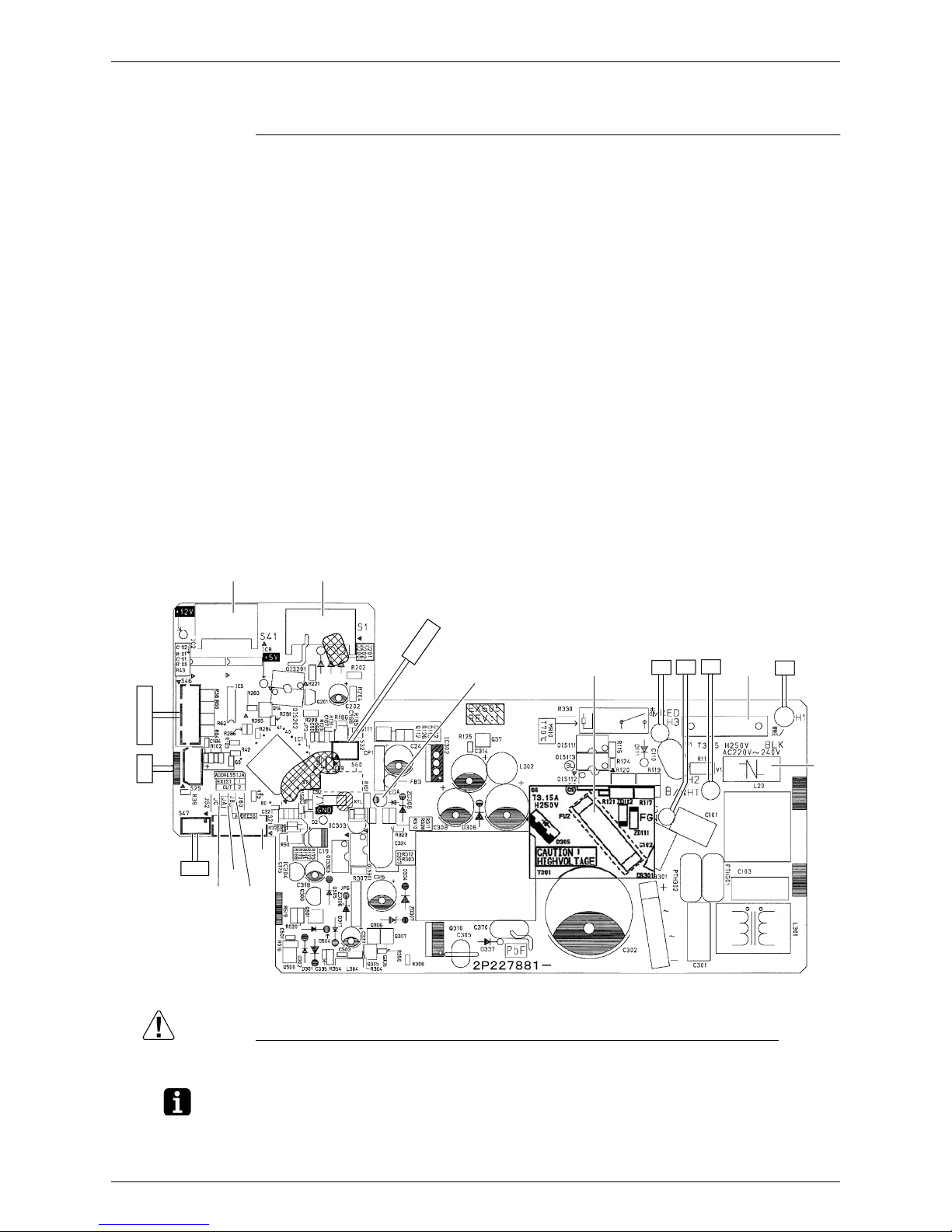
1. Indoor Unit
Control PCB
(PCB1)
Caution Replace the PCB if you accidentally cut the jumpers other than JA, JB, and JC.
Jumpers are necessary for electronic circuit. Improper operation may occur if you cut any of
them.
Note: The symbols in the parenthesis are the names on the appropriate wiring diagram.
1) S1 Connector for DC fan motor
2) S21 Connector for centralized control (HA)
3) S25 Connector for INTELLIGENT EYE sensor PCB
4) S32 Indoor heat exchanger thermistor
5) S41 Connector for swing motors
6) S46 Connector for display PCB
7) S47 Connector for signal receiver PCB
8) H1, H2, H3 Connector for terminal board (indoor - outdoor transmission)
9) FG Connector for terminal board (frame ground)
10) JA Address setting jumper
∗ Refer to page 114 for detail.
11) JB Fan speed setting when compressor stops for thermostat OFF
∗ Refer to page 116 for detail.
12) JC Power failure recovery function (auto-restart)
∗ Refer to page 116 for detail.
13) LED A LED for service monitor (green)
14) FU1 (F1U), FU2 Fuse (3.15 A, 250 V)
15) V1 Varistor
2P227881-2
FU1
V1
H1
H2FGH3
LED A
S32
S1S41
S46
S25
S47
S21
JB
JA
JC
FU2
Indoor Unit SiBE041011EC
13 Printed Circuit Board Connector Wiring Diagram
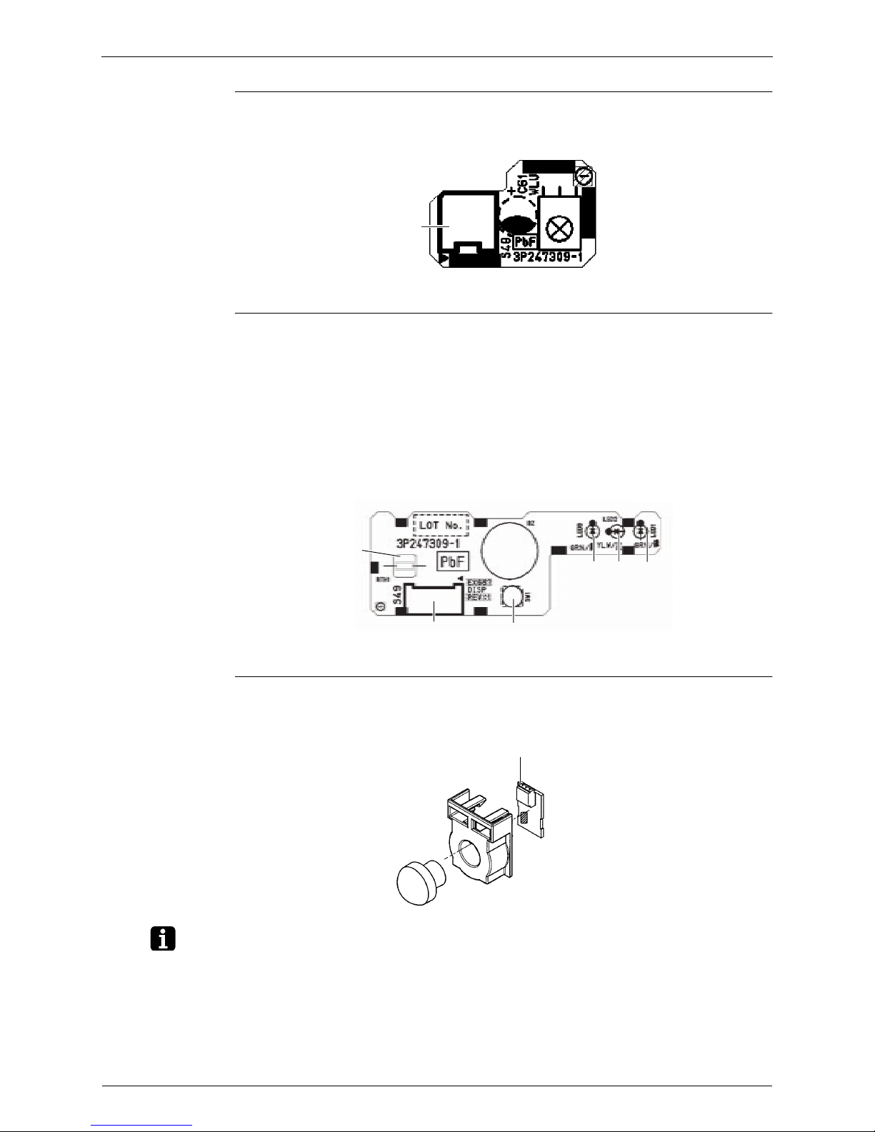
Signal Receiver
PCB (PCB2)
Display PCB
(PCB3)
INTELLIGENT
EYE Sensor PCB
(PCB4)
Note: The symbols in the parenthesis are the names on the appropriate wiring diagram.
1) S48 Connector for control PCB
S48
3P247309-1
1) S49 Connector for control PCB
2) SW1 Forced cooling operation ON/OFF button
∗ Refer to page 112 for detail.
3) LED1 (H1P) LED for operation (green)
4) LED2 (H2P) LED for timer (yellow)
5) LED3 (H3P) LED for INTELLIGENT EYE (green)
6) RTH1 (R1T) Room temperature thermistor
LED1LED2LED3
SW1S49
RTH1
3P247309-1
1) S36 Connector for control PCB
S36
3P227885-1
SiBE041011EC Outdoor Unit
Printed Circuit Board Connector Wiring Diagram 14
2. Outdoor Unit
2.1 RK(X)S60F3V1B, 71 Class
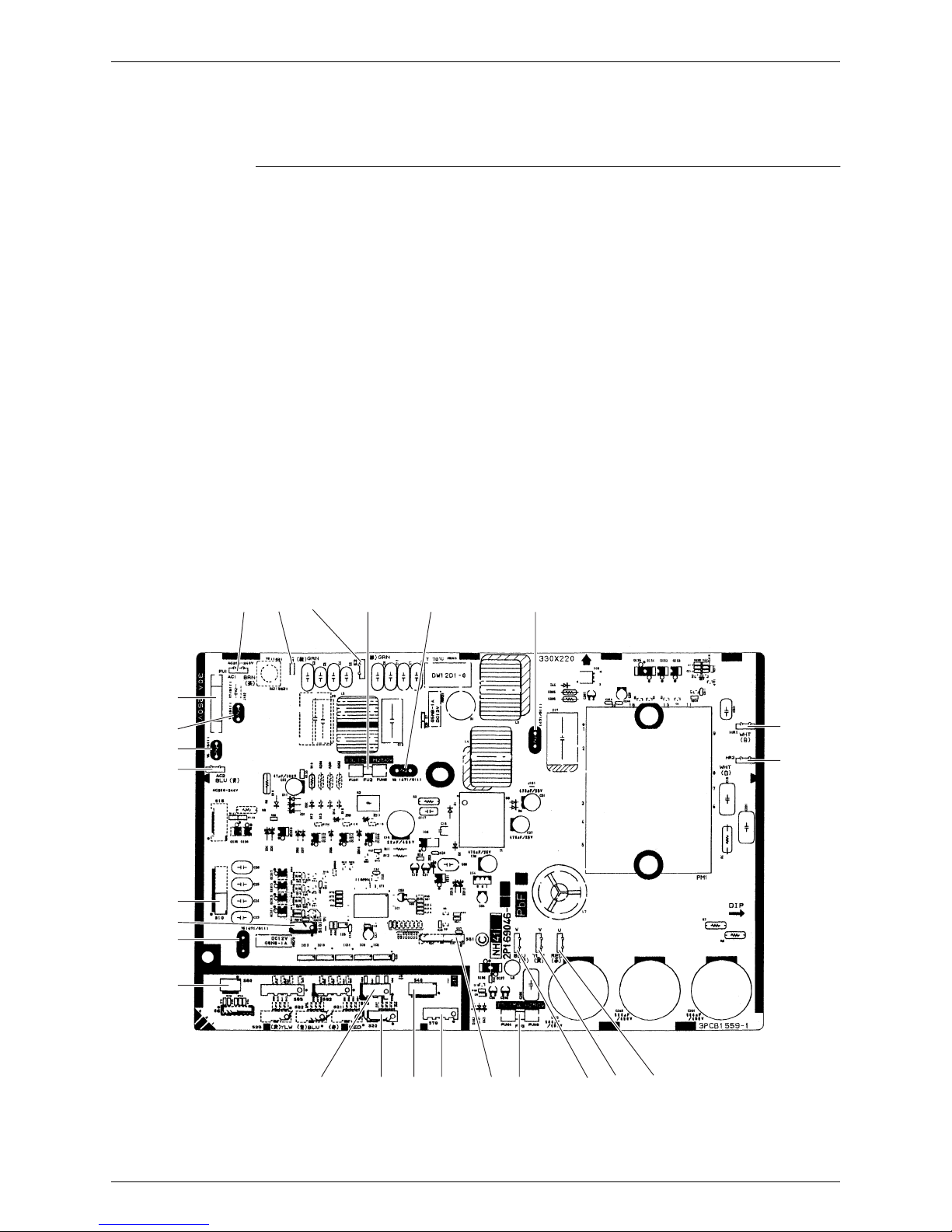
Main PCB (PCB 1)
RK(X)S60F3V1B
1) S10 Connector for terminal board (indoor - outdoor transmission)
2) S20 Connector for electronic expansion valve coil
3) S40 Connector for overload protector
4) S51, S101 Connector for service monitor PCB
5) S70 Connector for fan motor
6) S80 Connector for four way valve coil
7) S90 Connector for thermistors
(outdoor temperature, outdoor heat exchanger, discharge pipe)
8) AC1, AC2 Connector for terminal board (power supply)
9) HR1, HR2 Connector for reactor
10)E1, E2 Connector for earth wire
11)U, V, W Connector for compressor
12)FU1 Fuse (30 A, 250 V)
13)FU2, FU3 Fuse (3.15 A, 250 V)
14)V2, V3, V5
V6, V11
V9, V100
Varistor
(for 60 class)
(for 71 class)
V3
V11
AC1 E1 E2
HR1
HR2
2P169046-7
S40
S20
S70
S90
S51 W V U
S10
AC2
S101
V5
S80
V6
V2
FU2
(3.15A)
FU1
(30A)
FU3
(3.15A)
Outdoor Unit SiBE041011EC
15 Printed Circuit Board Connector Wiring Diagram
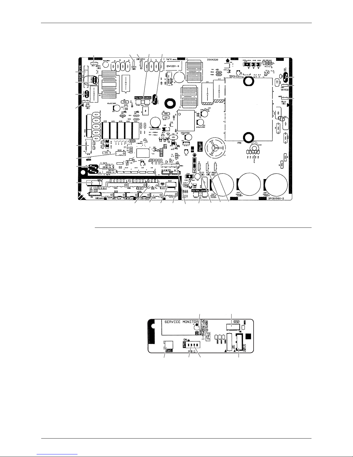
71 Class
Service Monitor
PCB (PCB 2)
SW4-A has no function. Keep it OFF.
AC1
E1 E2
V3
V2
V9
AC2
S10
S101
V5
S80
S90 S20 S40 S70 W V
U
2P229141-3
S51
V100
HR1
(white)
HR2
(blue)
FU3
(3.15A)
FU1
(30A)
FU2
(3.15A)
1) S52, S102 Connector for main PCB
2) LED A LED for service monitor (green)
3) SW1 Forced cooling operation ON/OFF button
∗ Refer to page 112 for detail.
4) SW4-B Switch for facility setting
∗ Refer to page 115 for detail.
5) SW4-C Switch for improvement of defrost performance
∗ Refer to page 116 for detail.
S102
SW1
3P169059-1
LED A
SW4-CSW4-B
S52
SiBE041011EC Outdoor Unit
Printed Circuit Board Connector Wiring Diagram 16
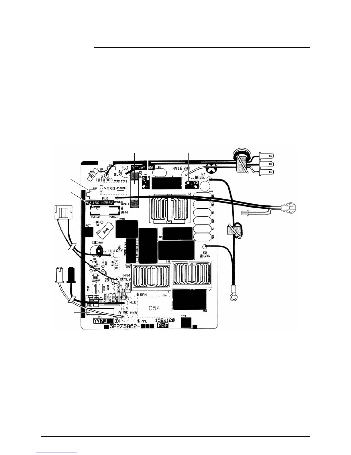
2.2 RK(X)S60F3V1B9, RXS60F4V1B
Filter PCB (PCB 1)
1) S11 Connector for S10 on main PCB
2) HL1, HN1, S Connector for terminal board
3) E1, E2 Terminal for earth wire
4) HL2, HN2 Connector for HL3 HN3 on main PCB
5) HL4, HN4 Connector for S12 on main PCB
6) FU1 Fuse (3.15 A, 250 V)
7) FU3 Fuse (30 A, 250 V)
8) V2, V3 Varistor
9) SW1 Forced cooling operation ON/OFF button
∗ Refer to page 112 for detail.
to S50
(on main PCB)
S
HL1
HN1
V3V2FU3
SW1
FU1
HN4, HL4
HN2 HL2
S11
E1, E2
3P273862-4
Outdoor Unit SiBE041011EC
17 Printed Circuit Board Connector Wiring Diagram
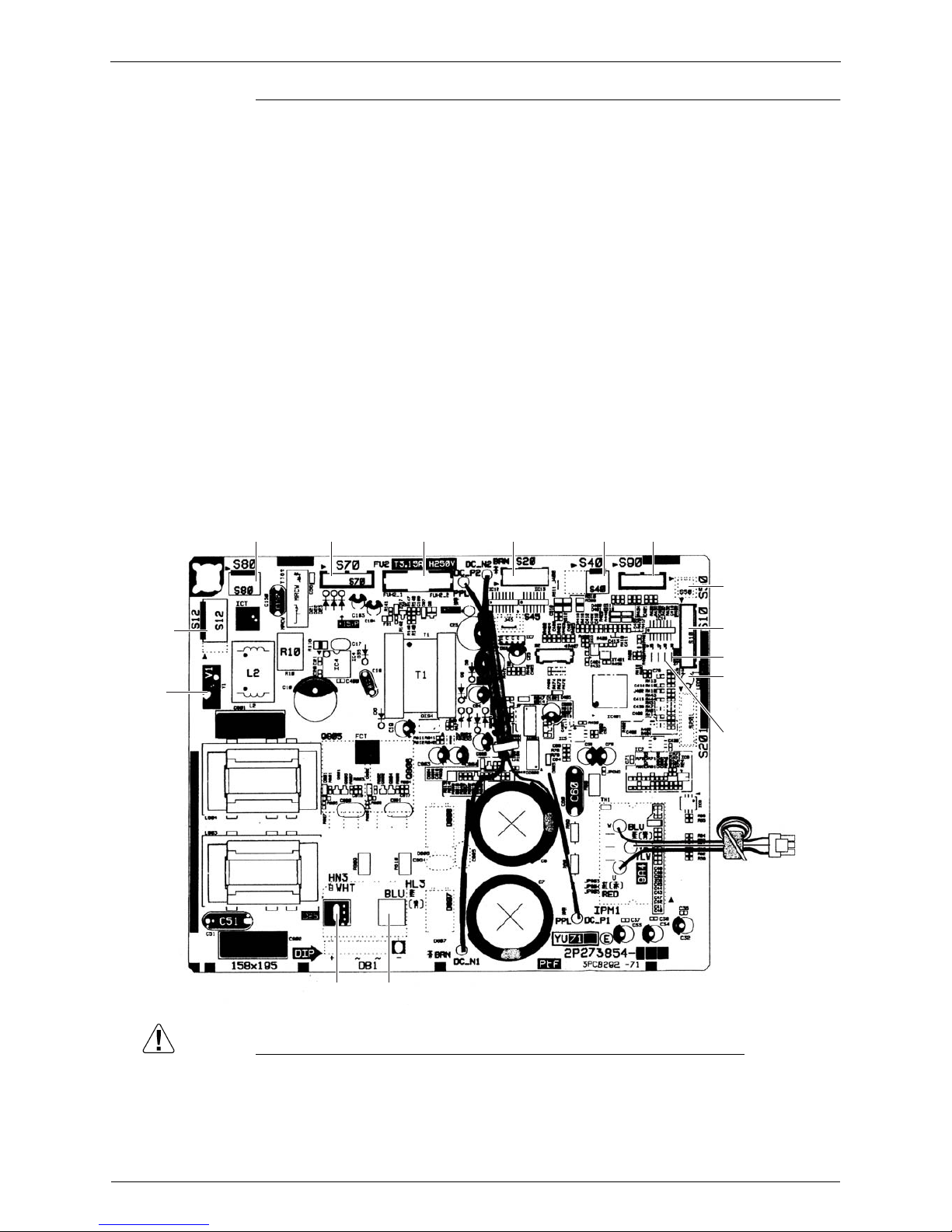
Main PCB (PCB 2)
Caution Replace the PCB if you accidentally cut the jumpers other than J6 and J8.
Jumpers are necessary for electronic circuit. Improper operation may occur if you cut any of
them.
1) S10 Connector for S11 on filter PCB
2) S12 Connector for HL4 HN4 on filter PCB
3) S20 Connector for electronic expansion valve coil
4) S40 Connector for overload protector
5) S50 Connector for magnetic relay
6) S70 Connector for fan motor
7) S80 Connector for four way valve coil
8) S90 Connector for thermistors
(outdoor temperature, outdoor heat exchanger, discharge pipe)
9) HL3, HN3 Connector for HL2 HN2 on filter PCB
10)U, V, W Terminal for compressor
11)FU2 Fuse (3.15 A, 250 V)
12)LED A LED for service monitor (green)
13)V1 Varistor
14)J6 Jumper for facility setting
∗ Refer to page 115 for detail.
15)J8 Jumper for improvement of defrost performance
∗ Refer to page 116 for detail.
S80
S10
2P273854-6
2P273854-7
S70 S20 S40 S90FU2
S50
LED A
J8
J6
U, V, W
HN3 HL3
S12
V1

SiBE041011EC
Function and Control 18
Part 4
Function and Control
1. Main Functions......................................................................................19
1.1 Temperature Control ..............................................................................19
1.2 Frequency Principle................................................................................19
1.3 Airflow Direction Control.........................................................................21
1.4 Fan Speed Control for Indoor Unit .........................................................22
1.5 Program Dry Operation ..........................................................................23
1.6 Automatic Operation...............................................................................24
1.7 Thermostat Control.................................................................................25
1.8 NIGHT SET Mode ..................................................................................26
1.9 ECONO Operation .................................................................................26
1.10 INTELLIGENT EYE Operation ...............................................................27
1.11 Inverter POWERFUL Operation .............................................................28
1.12 Clock Setting ..........................................................................................29
1.13 WEEKLY TIMER Operation ...................................................................30
1.14 Other Functions......................................................................................36
2. Function of Thermistor ..........................................................................37
3. Control Specification .............................................................................38
3.1 Mode Hierarchy ......................................................................................38
3.2 Frequency Control ..................................................................................39
3.3 Controls at Mode Changing / Start-up....................................................41
3.4 Discharge Pipe Temperature Control.....................................................43
3.5 Input Current Control ..............................................................................44
3.6 Freeze-up Protection Control .................................................................45
3.7 Heating Peak-cut Control .......................................................................45
3.8 Outdoor Fan Control...............................................................................46
3.9 Liquid Compression Protection Function................................................46
3.10 Defrost Control .......................................................................................47
3.11 Electronic Expansion Valve Control .......................................................48
3.12 Malfunctions ...........................................................................................51
Main Functions SiBE041011EC
19 Function and Control
1. Main Functions
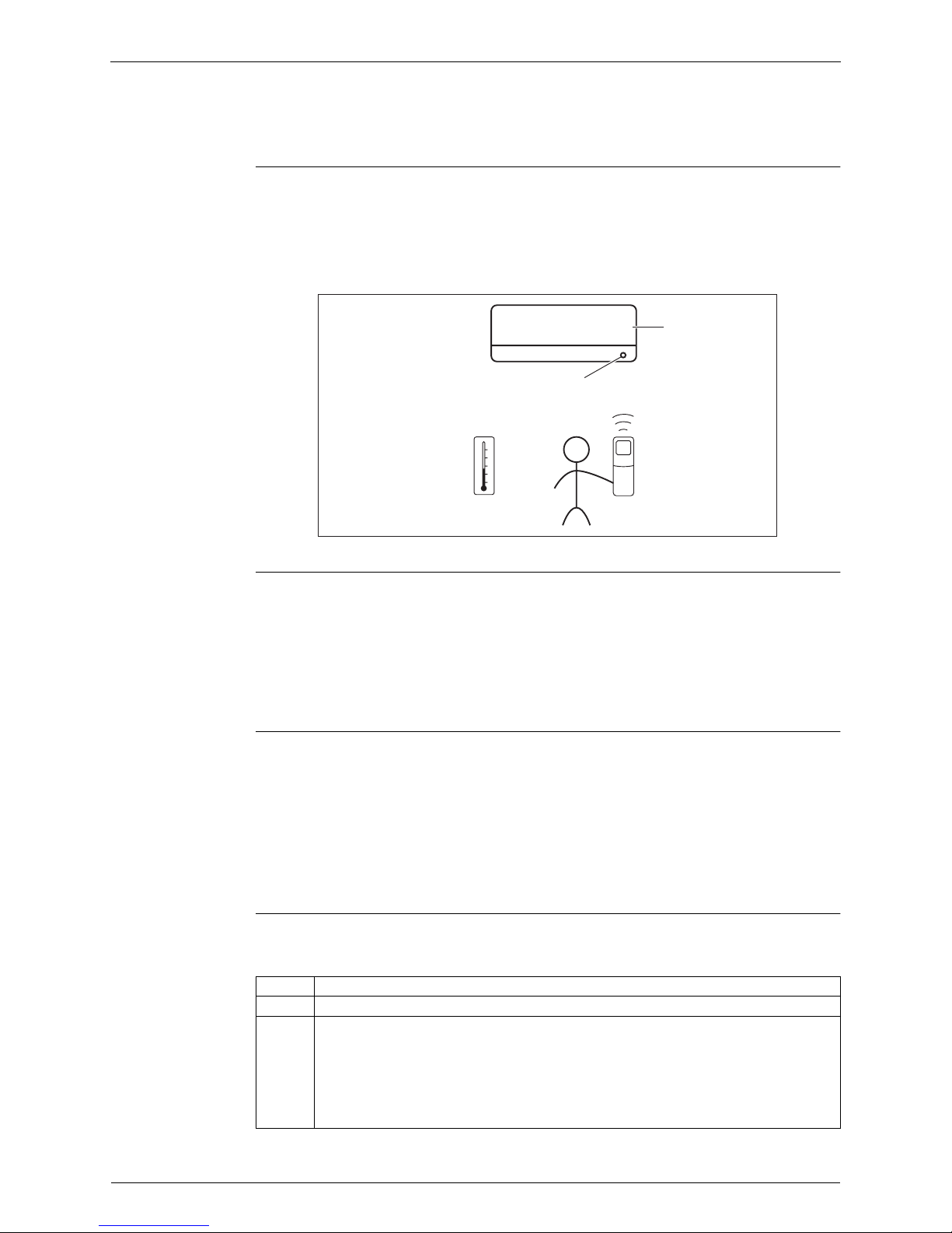
1.1 Temperature Control
Definitions of
Temperatures
The definitions of temperatures are classified as following.
Room temperature: temperature of lower part of the room
Set temperature: temperature set by remote controller
Room thermistor temperature: temperature detected by room temperature thermistor
Target temperature: temperature determined by microcomputer
Temperature
Control
The temperature of the room is detected by the room temperature thermistor. However, there is
a difference between the temperature detected by room temperature thermistor and the
temperature of lower part of the room, depending on the type of the indoor unit or installation
condition. Practically, the temperature control is done by the target temperature appropriately
adjusted for the indoor unit and the temperature detected by room temperature thermistor.
1.2 Frequency Principle
Control
Parameters
The frequency of the compressor is controlled by the following 2 parameters:
The load condition of the operating indoor unit
The difference between the room thermistor temperature and the target temperature
The target frequency is adapted by additional parameters in the following cases:
Frequency restrictions
Initial settings
Forced cooling operation
Inverter Principle To regulate the capacity, a frequency control is needed. The inverter makes it possible to
control the rotation speed of the compressor. The following table explains the conversion
principle:
Target temperature
Set temperature
Room temperature
Room thermistor temperature
(R12321)
Phase Description
1 The supplied AC power source is converted into the DC power source for the present.
2 The DC power source is reconverted into the three phase AC power source with variable
frequency.
When the frequency increases, the rotation speed of the compressor increases resulting
in an increase of refrigerant circulation. This leads to a larger amount of heat exchange
per unit.
When the frequency decreases, the rotation speed of the compressor decreases
resulting in a decrease of refrigerant circulation. This leads to a smaller amount of heat
exchange per unit.
 Loading...