

Daikin RTSYQ10PY1, RTSYQ14PY1, RTSYQ16PY1, RTSYQ20PY1, RTSQ8PY1 Installation manuals
...
INSTALLATION MANUAL
System air conditioner
[System]
RTSYQ10PY1
RTSYQ14PY1
RTSYQ16PY1
RTSYQ20PY1
[
Independent units
RTSQ8PY1
RTSQ10PY1
RTSQ12PY1
RTSQ14PY1
RTSQ16PY1
BTSQ20PY1
Installation manual
III-C
VRV
VRV
Conditionneur d’air VRV
Кондиционер системы VRV
VRV
III-C
VRV
System air conditioner
Installationsanleitung
III-C
System Klimaanlage
Manuel d’installation
III-C
Рóêоводство по монтажó
Bruksanvisning
III-C
System Klimaanlegg
Bruksanvisning
System luftkonditionerare
System
III-C
English
Deutsch
Français
Русский
Norsk
Svenska
]
Polski
DAIKIN.TCF.024D11/02-2009
TÜV Rheinlard EPS B.V.
0510260101
Umeda Center Bldg., 2-4-12, Nakazaki-Nishi,
Kita-Ku, Osaka, 530-8323 Japan
Low Voltage 2006/95/EC
Machinery Safety 98/37/EC
REYQ8PY1, REYQ10PY1, REYQ12PY1, REYQ14PY1, REYQ16PY1,
REYQ18PY1, REYQ20PY1, REYQ22PY1, REYQ24PY1, REYQ26PY1, REYQ28PY1, REYQ30PY1, REYQ32PY1,
REYQ34PY1, REYQ36PY1, REYQ38PY1, REYQ40PY1, REYQ42PY1, REYQ44PY1, REYQ46PY1, REYQ48PY1,
REYQ8PY1B, REYQ10PY1B, REYQ12PY1B, REYQ14PY1B, REYQ16PY1B,
REMQ8PY1, REMQ10PY1, REMQ12PY1, REMQ14PY1, REMQ16PY1,
BSVQ100PV1, BSVQ160PV1, BSVQ250PV1, BSV4Q100PV1, BSV6Q100PV1,
REYQ8P8Y1B, REYQ10P8Y1B, REYQ12P8Y1B, REYQ14P8Y1B, REYQ16P8Y1B,
RWEYQ8PY1, RWEYQ10PY1, RWEYQ16PY1, RWEYQ18PY1, RWEYQ20PY1, RWEYQ24PY1, RWEYQ26PY1, RWEYQ28PY1, RWEYQ30PY1,
Electromagnetic Compatibility 2004/108/EC
Shinri Sada
Manager Quality Control Department
1st of Mar. 2009
DAIKIN INDUSTRIES, LTD.
RXYQ5PY1(E), RXYQ8PY1(E), RXYQ10PY1(E), RXYQ12PY1(E), RXYQ14PY1(E), RXYQ16PY1(E), RXYQ18PY1(E),
RXYQ20PY1(E), RXYQ22PY1(E), RXYQ24PY1(E), RXYQ26PY1(E), RXYQ28PY1(E),
RXYQ30PY1(E), RXYQ32PY1(E), RXYQ34PY1(E), RXYQ36PY1(E), RXYQ38PY1(E),
RXYQ40PY1(E), RXYQ42PY1(E), RXYQ44PY1(E), RXYQ46PY1(E), RXYQ48PY1(E),
RXYQ50PY1(E), RXYQ52PY1(E), RXYQ54PY1(E),
RTSYQ10PY1, RTSYQ14PY1, RTSYQ16PY1, RTSYQ20PY1,
RTSQ8PY1, RTSQ10PY1, RTSQ12PY1, RTSQ14PY1, RTSQ16PY1,
BTSQ20PY1,
EN60335-2-40,
3P216950-1D
RTSQ8~12 RTSQ14 ·16 BTSQ20
1
2
1
2
3
50~100
2
(unit: mm)
9
≥300≥500
8
1
3
≥10
≥10
2
50~100
66
≥300≥500
9
≥10 ≥10
≥20
8
figure 1
1
2
2
≥1500
4
≥1000
≥1000
3
≥1500
≥1500
5
6
(unit: mm)
figure 3 figure 2
3
4
5
12
4
3
3
4
3
4
6
4
50~100
5
≥50
≥10
6
≥100
≥500
9
8
≥50
≥100
4
≥10
50~100
6
≥100≥500
9
8
5
27
≥300
≥200 ≥200 ≥400 ≥200≥200
≥300
66
3
4
2
5
1
figure 4
figure 6
1
≥100
3
≥100
≥100
22
2
4
5
≥100
6
3
≥100
≥100
figure 5
765
460
300
727
A
B
3
765
729
1
5
631
4
4
≥765
1
figure 7
1
2
4
3
5
4
6
3
9
5
5
12
4
7
88
figure 8
figure 9
figure 10
1
3
4
5
3
4
6
2
1
8
7
9
10
2
1
4
3
2
13
5
11
9
12
13
7
13
6
13
14
11
12
2
3
4
10
8
13
7
13
9
14
figure 11
figure 14
figure 12
1
4
3
14
6
5
14
8
14
11
14
14
7
2
5
4
3
13
9
8
14
13
14
12
figure 13
1
11
11
7
11
9
10
12
11
3
11
5
9
10
13
8
11
7
11
6
10
12
9
2
11
8
11
4
11
3
13
9
10
10
figure 15
1
2
3
4
8
7
5
7
266
6
A
1
B
2
7
1
1
2
3
4
5
1
4
6
8
17-1 17-2 17-3
figure 16
A
figure 18
figure 19
10
11
5
4
figure 17
34
1
2
5
1
2
3
1
2
1
B
2
556
4
E
D
3
4
E
D
E
D
E
D
E
D
7
8
figure 20
1
9
TO IN/D UNIT
TO OUT/D UNIT
F1 F2
F1 F2 Q1 Q2
3
TO MULTI UNIT
F1 F2 F1 F2 F1 F2 F1 F2 F1 F2 F1 F2
TO MULTI UNIT
Q1 Q2
9
7
10
TO IN/D UNIT
F1 F2 F1 F2 Q1 Q2
9
A1PA1PA1P
TO OUT/D UNIT
TO MULTI UNIT
88
1
2
3
12
13
7
14
15
15
17
16
18
9
7
6
8
10
7
2
6445
A1P A1P
TO MULTI UNIT
Q1 Q2
TO MULTI UNIT
Q1 Q2
9
figure 21
figure 22

3
(A1P)
1
2
6
6
(A1P)
3
5
4
4
F1 F2 F1 F2F1 F2
5
4
F1 F2 F1 F2
2
1
3
figure 23
figure 26
3
4
1
2
figure 24 figure 25
L1 L2 L3 N
7
5
6
11
1
8
9
4
2
9
3
4
E
D
1
3
2
4
E
D
10
12
17
6
5
7
8
9
10
6
16
9
7
8
3
4
15
19
7
10
10
15
L1 L2 L3 N
8
5
11
4
12
8
9
1
4
2
3
6
9
11
13
12
14
11
18
12 13 14
figure 27 figure 28
1
3
2
figure 29
1
2
3
4
: 21
: 22
10
11 12
9
6
16
4
5
: 23
: 24
17
18
8
7
19
13
15
14
20
1
1
2
3
figure 30 figure 31
1
5
6
8
5
71
9
10
1
2
1
3
4
2
: 17
: 18
4
5
6
7
: 19
: 20
1
2
7
6
89
3
13
5
4
14
15
7
3
10
12
11
16
figure 32
figure 33
figure 34
RTSYQ10PY1
RTSYQ14PY1
RTSYQ16PY1
RTSYQ20PY1
TWO-STAGE COMPRESSION
VRV System air conditioner
Meaning of WARNING and CAUTION notices
Installation manual
CONTENTS
1. FIRST OF ALL ......................................................................... 1
1-1. Safety precautions ............................................................1
1-2. Special notice of product................................................... 2
1-3. Disposal requirements ......................................................2
2. INTRODUCTION...................................................................... 2
2-1. About product.................................................................... 2
2-2. Technical and Electrical specifications .............................3
2-3. Main components.............................................................. 3
2-4. Combination...................................................................... 3
2-5. Standard supplied accessories ......................................... 3
2-6. Option accessory .............................................................. 3
3. SELECTION OF LOCATION ...................................................4
4. INSPECTING AND HANDLING THE UNIT ............................. 4
5. PLACING THE UNIT................................................................ 5
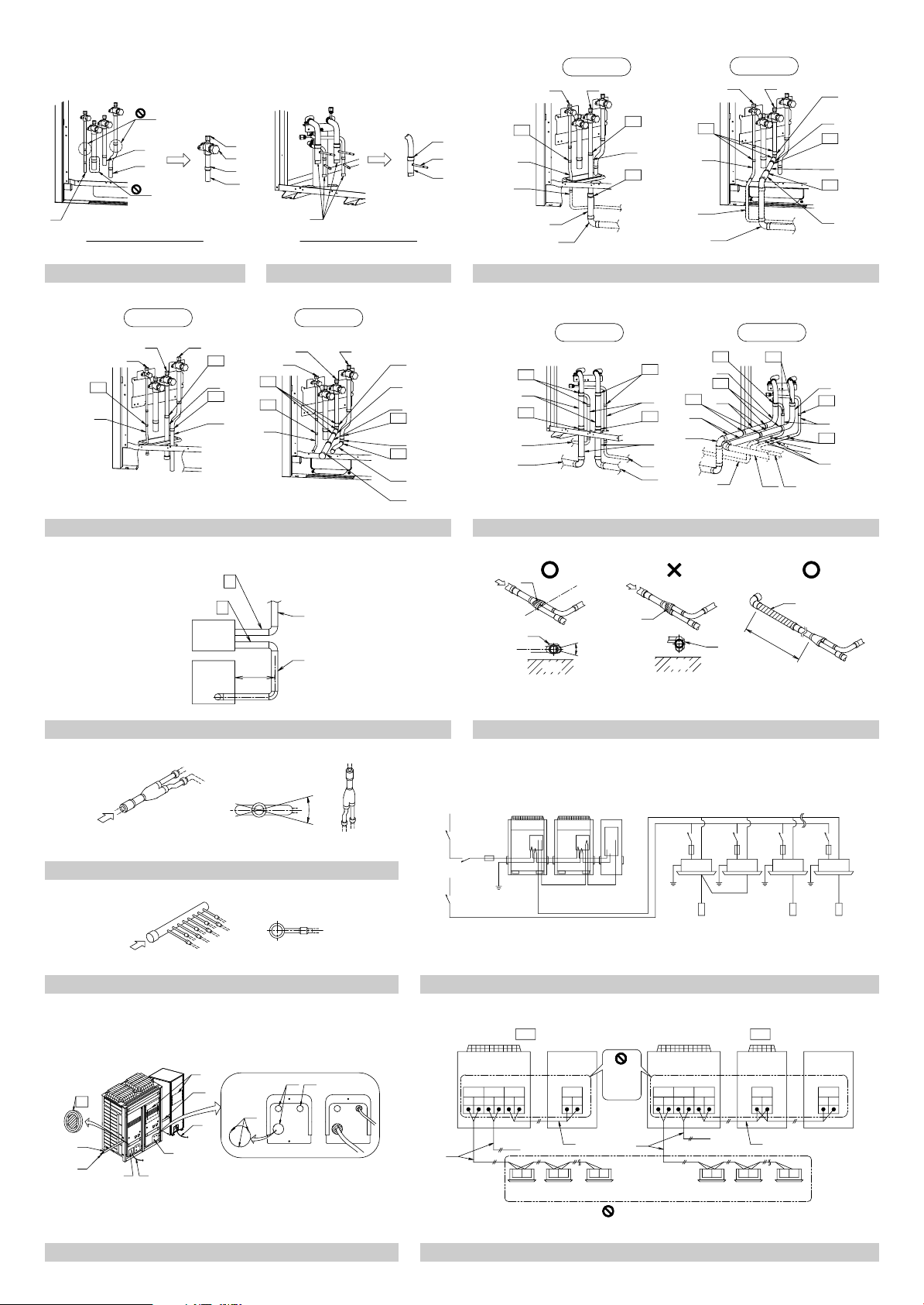
6. REFRIGERANT PIPING .......................................................... 5
6-1. Selection of piping material and Refrigerant
branching kit...................................................................... 5
6-2. Protection against contamination when installing pipes.... 5
6-3. Pipe connection ................................................................ 5
6-4. Connecting the refrigerant piping...................................... 6
6-5. Example of connection...................................................... 9
7. FIELD WIRING ...................................................................... 12
7-1. Power circuit, safety device and cable requirements...... 12
7-2. Wiring Connection Example for Whole System ..............12
7-3. Leading wire Procedure .................................................. 13
7-4. Transmission Wiring Connection Procedure................... 13
7-5. Power Wiring Connection Procedure.............................. 13
7-6. Procedure for Wiring Inside Units ...................................14
8. TESTS AND INSULATION WORK ........................................14
8-1. Air tight test and vacuum drying...................................... 14
8-2. Pipe insulation................................................................. 15
8-3. Checking of device and installation conditions ............... 15
9. ADDITIONAL REFRIGERANT CHARGE AND
CHECK OPERATION ............................................................ 16
9-1. Before working ................................................................ 16
9-2. Procedure of Additional Refrigerant charging ................. 18
9-3. Procedure of check operation ......................................... 20
10. ONSITE SETTINGS............................................................... 20
11. TEST RUN ............................................................................. 21
11-1. Before test run............................................................... 21
11-2. Test Run........................................................................21
11-3. Checks After Test Run.................................................. 21
12. CAUTION FOR REFRIGERANT LEAKS ............................... 21
1. FIRST OF ALL
• This document is an installation manual for the Daikin RTSYQ-P
Series VRV Inverter. Before installing the unit, read this manual
thoroughly, and following the instructions contained in it.
• After installation, do a test run to make sure the unit runs properly,
and then explain how to operate and take care of the unit to the
customer, using the operation manual.
• Lastly, make sure the customer keeps this manual, along with the
operation manual, in a safe place.
1-1 Safety precautions
• Please read these “Safety precautions” carefully before installing
air conditioning unit and be sure to install it correctly.
• After completing installation, conduct a trial operation to check for
faults and explain to the customer how to operate the air conditioner and take care of it with the aid of the operation manual.
Ask the customer to store the installation manual along with the
operation manual for future reference.
Warnin g ........Failure to follow these instructions properly may
result in personal injury or loss of life.
Caution.........Failure to observe these instructions properly
may result in property damage or personal
injury, which may be serious depending on the
circumstances.
Warnin g
Ask your dealer or qualified personnel to carry out installation work.
•
Do not attempt to install the air conditioner yourself. Improper
installation may result in water leakage, electric shocks or fire.
• Install the air conditioner in accordance with the instructions in
this installation manual.
Improper installation may result in water leakage, electric shocks or fire.
• When installing the unit in a small room, take measures against to
keep refrigerant concentration from exceeding allowable safety
limits in the event of refrigerant leakage.
Contact the place of purchase for more information. Excessive
refrigerant in a closed ambient can lead to oxygen deficiency.
• Be sure to use only the specified accessories and parts for installation work.
Failure to use the specified parts may result in the unit falling,
water leakage, electric shocks or fire.
• Install the air conditioner on a foundation strong enough to withstand the weight of the unit.
A foundation of insufficient strength may result in the equipment
falling and causing injury.
• Carry out the specified installation work after taking into account
strong winds, typhoons or earthquakes.
Failure to do so during installation work may result in the unit falling and causing accidents.
Make sure that a separate power supply circuit is provided for this unit
•
and that all electrical work is carried out by qualified personnel according to local and national regulations and this installation manual.
An insufficient power supply capacity or improper electrical construction may lead to electric shocks or fire.
• Be sure to earth the air conditioner.
Do not earth the unit to a utility pipe, lightning conductor
or telephone earth lead. Imperfect earthing may result in
electric shocks or fire.
A high surge current from lightning or other sources may cause
damage to the air conditioner.
• Be sure to install an earth leakage breaker.
Failure to install an earth leakage breaker may result in electric
shocks or fire.
• Be sure to switch off the unit before touching any electrical parts.
• Make sure that all wiring is secured, the specified wires are used,
and that there is no strain on the terminal connections or wires.
Improper connections or securing of wires may result in abnormal
heat build-up or fire.
• When wiring the power supply and connecting the remote controller wiring and transmission wiring, position the wires so that the
EL. COMPO. BOX lid can be securely fastened.
Improper positioning of the EL. COMPO. BOX lid may result in
electric shocks, fire or the terminals overheating.
• If refrigerant gas leaks during installation, ventilate the area
immediately.
Toxic gas may be produced if the refrigerant comes into contact
with fire.
• After completing installation, check for refrigerant gas leakage.
Toxic gas may be produced if the refrigerant gas leaks into the
room and comes into contact with a source of fire, such as a fan
heater, stove or cooker.
• Do not directly touch refrigerant that has leaked from refrigerant
pipes or other areas, as there is a danger of frostbite.
• Do not allow children to climb on the outdoor unit or function unit
and avoid placing objects on the unit.
Injury may result if the unit becomes loose and falls.
1 English
Caution
• While following the instructions in this installation manual,
install drain piping to ensure proper drainage and insulate piping to prevent condensation.
Improper drain piping may result in indoor water leakage and
property damage.
• Install the indoor, outdoor and function units, power cord and connecting wires at least 1 meter away from televisions or radios to
prevent picture interference and noise.
(Depending on the incoming signal strength, a distance of 1 meter
may not be sufficient to eliminate noise.)
• Remote controller (wireless kit) transmitting distance can be
shorter than expected in rooms with electronic fluorescent lamps
(inverter or rapid start types).
Install the indoor unit as far away from fluorescent lamps as possible.
• Make sure to provide for adequate measures in order to prevent
that the outdoor unit be used as a shelter by small animals.
Small animals making contact with electrical parts can cause malfunctions, smoke or fire. Please instruct the customer to keep the
area around the unit clean.
• Do not install the air conditioner in the following locations:
1. Where there is a high concentration of mineral oil spray or
vapour (e.g. a kitchen).
Plastic parts will deteriorate, parts may fall off and water leakage could result.
2. Where corrosive gas, such as sulphurous acid gas, is pro-
duced.
Corroding of copper pipes or soldered parts may result in
refrigerant leakage.
3. Near machinery emitting electromagnetic radiation.
Electromagnetic radiation may disturb the operation of the
control system and result in a malfunction of the unit.
4. Where flammable gas may leak, where there is carbon fibre or
ignitable dust suspensions in the air, or where volatile flammables such as paint thinner or gasoline are handled.
Operating the unit in such conditions may result in fire.
• The air conditioner is not intended for use in a potentially explosive atmosphere.
1-2 Special notice of product
[CLASSIFICATION]
This air conditioner comes under the term “appliances not accessible
to the general public”.
[EMC CHARACTERISTICS]
This system is a class A product. In a domestic environment this
product may cause radio interference in which case the user may be
required to take adequate measures.
[REFRIGERANT]
This system use R410A refrigerant.
• The refrigerant R410A requires that strict precautions be
observed for keeping the system clean, dry and tightly sealed.
Read the chapter “REFRIGERANT PIPING” carefully and follow
these procedures correctly.
A. Clean and dry
Strict measures must be taken to keep impurities (including
SUNISO oil and other mineral oils as well as moisture) out of
the system.
B. Tightly sealed
Take care to keep the system tight when installing.
R410A contains no chlorine, does not destroy the ozone layer
and so does not reduce the earth’s protection against harmful
ultraviolet radiation. R410A will contribute only slightly to the
greenhouse effect if released into the atmosphere.
• Since R410A is a mixed refrigerant, the required additional refrigerant must be charged in its liquid state. (If the system is charged
with refrigerant in its gaseous state, due to composition change,
the system will not function normally.)
Limit by the total maximum refrigerant charge
The total maximum refrigerant charge of a VRV system must be
below 100kg, this to be in accordance with CE requirement
(EN60335-2-40 standard).
This means that in case the total maximum refrigerant charge of the
system (factory and additional charge) is equal to or more than
100kg you must divide your multiple outdoor system into smaller
independent systems, each containing less than 100kg refrigerant
charge.
For factory charge, refer to the unit name plate.
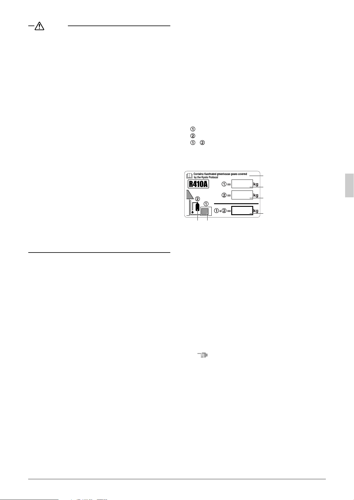
Important information regarding the refrigerant used
This product contains fluorinated greenhouse gases covered by the
Kyoto Protocol. Do not vent gases into the atmosphere.
Refrigerant type : R410A
(1)
GWP
value : 1975
(1)
GWP = global warming potential
Please fill in with indelible ink,
the factory refrigerant charge of the product,
the additional refrigerant amount charged in the field and
+ the total refrigerant charge on the refrigerant charge label
supplied with the product.
The filled out label must be adhered in the proximity of the product
charging port (e.g. onto the inside of the service cover).
4
1 factory refrigerant charge
of the product : see unit
name plate
1
2 additional refrigerant
2
amount charged in the field
3 total refrigerant charge
3
4 Contains fluorinated
5
6
(2)
In case of multiple outdoor systems, only 1 label must be adhered,
greenhouse gases covered
by the Kyoto Protocol
5 outdoor unit
6 refrigerant cylinder and
manifold for charging
(2)
mentioning the total factory refrigerant charge of all outdoor units
connected on the refrigerant system.
[DESIGN PRESSURE]
Since design pressure is 4.0MPa or 40bar (for R407C units : 3.3MPa
or 33bar), the wall thickness of pipes should be more carefully
selected in accordance with the relevant local and national regulations.
1-3 Disposal requirements
Disposal requirements
Dismantling of the unit, treatment of the refrigerant, of oil and of other
parts must be done in accordance with relevant local and national
legislation.
2. INTRODUCTION
Note
• This manual provides information on the installation of the out-
door unit and function unit. Follow the instructions provided in the
manual and install both the outdoor unit and function unit.
• For the installation of the indoor unit, refer to the installation manual provided with the indoor unit.
• Option accessories (sold separately) are required for the installation of the products. Refer to “2-6 Option accessory” for details.
2-1 About product
RTSYQ-P series are designed for outdoor installation and used for
•
cooling and heating aplications. The outdoor system consists of the
RTSQ8-16P outdoor unit and BTSQ20P function unit in combination.
Only the outdoor unit or function unit cannot be used independently.
Refer to “
2-4 Combination
With this system, rated cooling capacity from 28.0kW to 55.9kW
and rated heating capacity from 31.5kW to 62.5kW can be
achieved.
” for concrete system configurations.
English 2
• The indoor units that combined with RTSYQ-P system for air conditioning are Daikin VRV series indoor units that compatible with
R410A. To learn which indoor units are compatible with R410A,
refer to the product catalogs. To combine with other refrigerant
indoor unit will cause malfunction.
2-2 Technical and Electrical specifications
Refer to the Engineering Data Book for the complete list of specifications.
2-3 Main components
For main components and function of the main components, refer to
the Engineering Data Book.
2-4 Combination
• The following table shows a list of system names, system config-
uration models, and the capacity of each connectable indoor unit.
<Single outdoor unit system>
System name
Composition unit
Outdoor unit Function unit
Total capacity
of indoor units
RTSYQ10PY1 RTSQ10PY1 BTSQ20PY1 125 - 325
RTSYQ14PY1 RTSQ14PY1 BTSQ20PY1 175 - 455
RTSYQ16PY1 RTSQ16PY1 BTSQ20PY1 200 - 520
* The RTSQ8P or RTSQ12P unit cannot be used as a configura-
tion unit of single outdoor unit system.
<Multi outdoor unit system>
System name
RTSYQ20PY1
Composition unit
Outdoor unit Function unit
RTSQ8PY1
RTSQ12PY1
BTSQ20PY1 250 - 650
Total capacity
of indoor units
* The RTSQ10P, RTSQ14P, or RTSQ16P unit cannot be used as
a configuration unit of the multi outdoor unit system.
* The BHFP30AC56 outdoor unit multi connection piping kit (sold
separately) is required for the piping connections of two outdoor
units.
Note
• Install the function unit on the right-hand side of the outdoor unit.
If the order of arrangement differs, the shape of the provided piping will not be compatible, in which case a substitute connection
pipe will be required on site.
Outdoor unit
Function unit
*Only in case of multi
outdoor unit system
AB
(*)
To indoor units
Outdoor unit multi
connection piping kit(*)
• If the total capacity of the connected indoor units exceeds the
capacity of the outdoor unit, cooling and heating performance
may drop when running the indoor units. See the capacity table in
the Engineering Data Book for details.
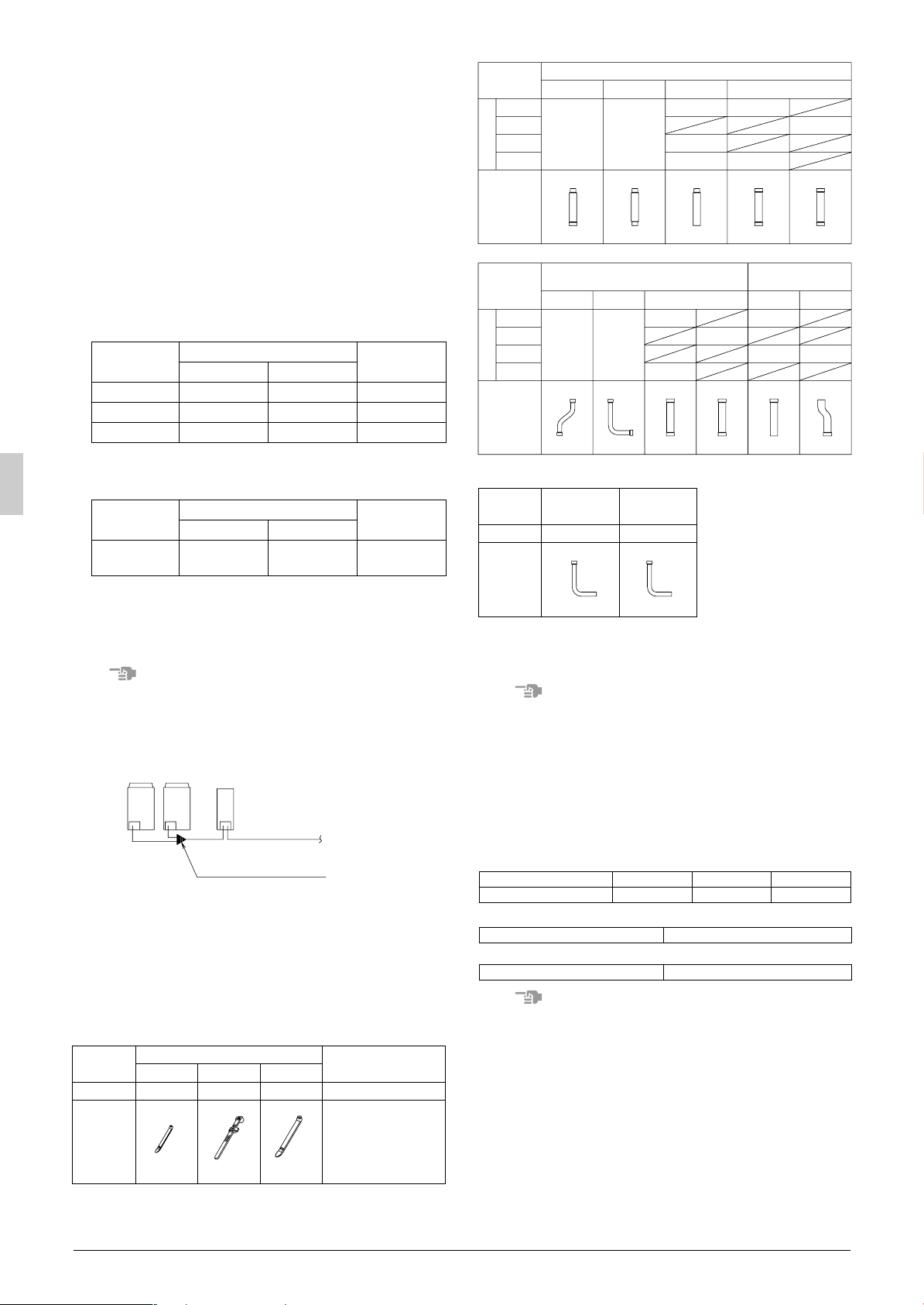
2-5 Standard supplied accessories
Confirm the following accessories are included. The storage location
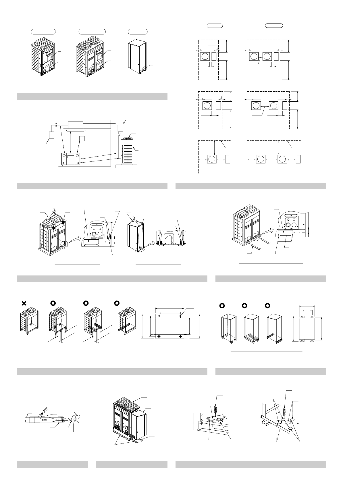
of the accessories is shown in figure 1.
< Accessories included in outdoor unit >
Name Manuals, etc.
Quantity 11 pcs. 2 pcs. 1 pc. 1 pc. about each item
Shape
(1) (2) (3)
(Small) (Large)
Clamp
• Operation manual
• Installation manual
• “REQUEST FOR THE
INDICATION” label
(Installation records)
• Refrigerant charge label
• Declaration of conformity
Name
8 type
10 type
12 type
Quantity
14 · 16 type
Shape
Name
8 type
10 type
12 type
Quantity
14 · 16 type
Shape
(1) (2) (3) (4)
1 pc. 1 pc.
Liquid side accessory pipe
(1) (2) (3) (2)(1)
1 pc. 1 pc.
Gas side accessory pipe
1 pc.
2 pcs.
3 pcs.
2 pcs. 1 pc.
2 pcs.
2 pcs.
φ12.7 φ9.5
2 pcs.
2 pcs.
2 pcs.
φ25.4 φ22.2
Equalizer side
accessory pipe
2 pcs.1 pc.
< Accessories included in function unit >
Gas side
Name
Quantity 2 pcs.
Shape
accessory
pipe(5)
φ25.4 φ12.7
Liquid side
accessory
pipe(4)
2 pcs.
(Refer to figure 1)
1. Clamps, Manuals, etc.
2. Accessory pipes
Note
• Accessories are divided separately for the outdoor unit and func-
tion unit. Check the accessories for both units.
• Do not throw away any of the accessories until installation is complete. They are needed for installation work.
Request the user to keep the explanation documents after the
installation work is completed.
2-6 Option accessory
To install the outdoor units, the following optional parts are also required.
To select an optimum kit, refer to “6. REFRIGERANT PIPING”.
• Refrigerant branching kit
REFNET header
REFNET joint
• Outdoor unit connection piping kit
Kit name BHFP30A56
• Pipe size reducer
for REFNET header KHRP26M73HP
Note
• Make sure that any separately purchased accessories are
designed for use with R410A.
• The outdoor unit multi connection piping kit is required for the
multi outdoor unit system only.
KHRP26M22H KHRP26M33H KHRP26M72H
KHRP26A22T KHRP26A33T KHRP26A72T
3 English

3. SELECTION OF LOCATION
Select a location for installation that meets the following conditions
and get the customer’s permission.
There is no danger of fire due to leakage of inflammable gas.
(1)
Select the location of the unit in such a way that neither the dis-
(2)
charged air nor the sound generated by the unit disturb anyone.
The foundation is strong enough to support the weight of the unit
(3)
and the floor is flat to prevent vibration and noise generation.
The piping length between the outdoor unit and the indoor unit
(4)
may not exceed the allowable piping length.
(Refer to “6. REFRIGERANT PIPING”)
Locations where the unit’s suction vent and outlet vent do not
(5)
generally face the wind.
Wind blowing directly into the suction or outlet vents will interfere
with the unit’s operation.
If necessary, install some kind of obstruction to block the wind.
The space around the unit is adequate for servicing and the min-
(6)
imum space for air inlet and air outlet is available.
(See the “Installation Space Examples” for the minimum space
requirements.)
Installation Space Examples
• The installation space requirement shown in figure 2 is a refer-
ence for cooling operation when the outdoor temperature is 35°C.
If the design outdoor temperature exceeds 35°C or the heat load
exceeds maximum capacity in all the outdoor unit, take an even
large space on the intake shown in figure 2.
• During installation, install the units using the most appropriate of
the patterns shown in figure 2 for the location in question, taking
into consideration human traffic and wind.
If the number of units installed is more than that shown in the pattern in figure 2, install the units so there are no short circuits.
• As regards space in front of the unit, consider the space needed
for the local refrigerant piping when installing the units.
• If a snowbreak hood (sold separately) is mounted, secure the
required space of installation including the outer dimensions of
the product and snowbreak hood.
• If the work conditions in figure 2 do not apply, contact your dealer
or Daikin directly.
(Refer to figure 2)
1. In case of single outdoor unit system
2. In case of multi outdoor unit system
3. Pattern 1
4. Pattern 2
5. Pattern 3
6. Front side
7. No limit to wall height
8. Service space of front side
9. Service space of suction side
For Patterns 1 and 2 in figure 2 :
• Wall height for front side – no higher than 1500 mm.
• Wall height on the suction side – no higher than 500 mm.
• Wall height for sides – no limit.
If the height is exceeded the above, calculate h1 and h2 shown in
the figure below, and add h2/2 to the service space of front side
and h1/2 to the service space of suction side.
h2
<Front side> <Suction side>
h2
++
500
or more
2
1500
Note
An inverter air conditioner may cause electronic noise gener-
(1)
ated from AM broadcasting. Examine where to install the
main air conditioner and electric wires, keeping proper distances away from stereo equipment, personal computers, etc.
Particularly for locations with weak reception, ensure there is
a distance of at least 3 meters for indoor remote controllers,
place power wiring and transmission wiring in conduits, and
ground the conduits.
Service
space
or more
h1
2
h1
500
(Refer to figure 3)
1. Indoor unit
2. Branch switch, overcurrent breaker
3. Remote controller
4. Personal computer or radio
5. Air outlet
6. Rear side suction grille
When installing in a locations where there is heavy snowfall,
(2)
implement the following snow measures.
• Install the outdoor unit and function unit on a mount (procured locally) so that they may not be buried or covered
with snowfall while the bottom frame will be 200 to 300 mm
higher than the surface of the deposited snow.
• Mount the snowbreak hood (sold separately) and dismount
the rear suction grille (see fig. 3).
When mounting the snowbreak hood (sold separately) to
(3)
the air inlet, make sure that the air outlet of the snow protection food will be located right angles to the winter wind or in
the leeward direction.
If the outdoor temperature of the place of installation is low
(4)
in winter and defrost water discharged from the system
freezes while the system is in defrost operation in heating
mode, provide a sufficient space between the bottom frame
of the outdoor unit and the foundation side. (A space of 500
to 1000 mm is recommended.)
If condensate may drip on downstairs (or walkway) depend-
(5)
ing on the floor condition, take a measure such as the installation of drain pan (field supply).
The refrigerant R410A itself is nontoxic, nonflammable and is
(6)
safe. If the refrigerant should leak however, its concentration
may exceed the allowable limit depending on room size. Due to
this it could be necessary to take measures against leakage.
See “12. CAUTION FOR REFRIGERANT LEAKS” for details.
4. INSPECTING AND HANDLING THE UNIT
• At delivery, the package should be checked and any damage
should be reported immediately to the carrier claims agent.
• When handling the unit, take into account the following:
(1)
(2)
(3)
Note
(4)
Fragile, handle the unit with care.
Keep the unit upright in order to avoid compressor damage.
Decide on the transportation route.
If hanging the unit, keep the following points in mind and hang the
unit following the procedure shown in figure 4.
• Use a sling sufficiently strong to hold the mass of the unit.
• Use 2 sling of at least 8m long.
• Place extra cloth or boards in the locations where the casing
comes in contact with the sling to prevent damage.
•
Hoist the unit making sure it is being lifted at its center of gravity.
In the case of transporting the outdoor unit by forklift, insert the
fork into the opening (large) under the bottom of the outdoor unit.
(Refer to figure 5)
The function unit is not provided with any opening for fork insertion.
• Apply a filler cloth on a fork to prevent coating of the bottom frame
from coming off and rust from occurring when bringing the unit
using a forklift.
After the outdoor unit is installed, remove the transportation
bracket (yellow) by pushing the hook mounted to the opening
(large) of the outdoor unit. (Refer to figure 5)
(Refer to figure 4)
1. Slinging procedure for outdoor unit
2. Slinging procedure for function unit
3. Sling
4. Patch plate or path cloth
5. Opening (large)
6. Opening (small)
English 4
 Loading...