

Page 1

INSTALLATION MANUAL
Air cooled refrigeration condensing unit
LREQ15B7Y1R
LREQ20B7Y1R
Page 2
CE - VYHLÁSENIE-ZHODY
<A> DAIKIN.TCF.023 C9/06-2012
<B> TÜV (NB1856)
<C> 0502240101
<D> Daikin.TCFP.001
<E> AIB Vinçotte (NB0026)
<F> D1
<G> —
<H>
II
CE - UYUMLULUK-BİLDİRİSİ
CE - ATITIKTIES-DEKLARACIJA
CE - ATBILSTĪBAS-DEKLARĀCIJA
CE - IZJAVA O SKLADNOSTI
CE - VASTAVUSDEKLARATSIOON
CE - ДЕКЛАРАЦИЯ-ЗА-ϹЪОТВЕТСТВИЕ
deklaruje na własną i wyłączną odpowiedzialność, że modele klimatyzatorów, których dotyczy niniejsza deklaracja:
declară pe proprie răspundere că aparatele de aer condiţionat la care se referă această declaraţie:
z vso odgovornostjo izjavlja, da so modeli klimatskih naprav, na katere se izjava nanaša:
kinnitab oma täielikul vastutusel, et käesoleva deklaratsiooni alla kuuluvad kliimaseadmete mudelid:
декларира на своя отговорност, че моделите климатична инсталация, за които се отнася тази декларация:
o
19
deklarerar i egenskap av huvudansvarig, att luftkonditioneringsmodellerna som berörs av denna deklaration innebär att:
s
11
déclare sous sa seule responsabilité que les appareils d'air conditionné visés par la présente déclaration:
f
03
x
20
erklærer et fullstendig ansvar for at de luftkondisjoneringsmodeller som berøres av denne deklarasjonen, innebærer at:
n
12
verklaart hierbij op eigen exclusieve verantwoordelijkheid dat de airconditioning units waarop deze verklaring betrekking heeft:
l
04
b
21
ilmoittaa yksinomaan omalla vastuullaan, että tämän ilmoituksen tarkoittamat ilmastointilaitteiden mallit:
j
13
declara baja su única responsabilidad que los modelos de aire acondicionado a los cuales hace referencia la declaración:
e
05
visiška savo atsakomybe skelbia, kad oro kondicionavimo prietaisų modeliai, kuriems yra taikoma ši deklaracija:
t
22
prohlašuje ve své plné odpovědnosti, že modely klimatizace, k nimž se toto prohlášení vztahuje:
c
14
dichiara sotto sua responsabilità che i condizionatori modello a cui è riferita questa dichiarazione:
i
06
m
r
17
18
CE - DEKLARACJA-ZGODNOŚCI
CE - DECLARAŢIE-DE-CONFORMITATE
CE - IZJAVA-O-USKLAĐENOSTI
CE - MEGFELELŐSÉGI-NYILATKOZAT
CE - ERKLÆRING OM-SAMSVAR
CE - ILMOITUS-YHDENMUKAISUUDESTA
CE - PROHLÁŠENÍ-O-SHODĚ
заявляет, исключительно под свою ответственность, что модели кондиционеров воздуха, к которым относится настоящее заявление:
erklærer under eneansvar, at klimaanlægmodellerne, som denne deklaration vedrører:
u
q
09
10
CE - FÖRSÄKRAN-OM-ÖVERENSTÄMMELSE
CE - DECLARAÇÃO-DE-CONFORMIDADE
CE - ЗАЯВЛЕНИЕ-О-СООТВЕТСТВИИ
CE - OVERENSSTEMMELSESERKLÆRING
CE - DECLARACION-DE-CONFORMIDAD
CE - DICHIARAZIONE-DI-CONFORMITA
CE - ∆HΛΩΣΗ ΣΥΜΜΟΡΦΩΣΗΣ
declares under its sole responsibility that the air conditioning models to which this declaration relates:
erklärt auf seine alleinige Verantwortung daß die Modelle der Klimageräte für die diese Erklärung bestimmt ist:
a
d
CE - DECLARATION-OF-CONFORMITY
Daikin Europe N.V.
CE - KONFORMITÄTSERKLÄRUNG
CE - DECLARATION-DE-CONFORMITE
CE - CONFORMITEITSVERKLARING
01
02
ar pilnu atbildību apliecina, ka tālāk uzskaitīto modeļu gaisa kondicionētāji, uz kuriem attiecas šī deklarācija:
vyhlasuje na vlastnú zodpovednosť, že tieto klimatizačné modely, na ktoré sa vzťahuje toto vyhlásenie:
tamamen kendi sorumluluǧunda olmak üzere bu bildirinin ilgili olduǧu klima modellerinin aşaǧıdaki gibi olduǧunu beyan eder:
v
k
w
23
24
25
izjavljuje pod isključivo vlastitom odgovornošću da su modeli klima uređaja na koje se ova izjava odnosi:
teljes felelőssége tudatában kijelenti, hogy a klímaberendezés modellek, melyekre e nyilatkozat vonatkozik:
y
h
15
16
δηλώνει με αποκλειστική της ευθύνη ότι τα μοντέλα των κλιματιστικών συσκευών στα οποία αναφέρεται η παρούσα δήλωση:
declara sob sua exclusiva responsabilidade que os modelos de ar condicionado a que esta declaração se refere:
g
p
07
08
Direktive z vsemi spremembami.20Direktiivid koos muudatustega.21Директиви, с техните изменения.22Direktyvose su papildymais.23Direktīvās un to papildinājumos.24Smernice, v platnom znení.25Deǧiştirilmiş halleriyle Yönetmelikler.
19
.
инструкции:
документи, при условие, че се използват съгласно нашите
съответс тват на следните стандарти или други нормативни
21
spełniają wymogi następujących norm i innych dokumentów
normalizacyjnych, pod warunkiem że używane są zgodnie z
naszymi instrukcjami:18sunt în conformitate cu următorul (următoarele) standard(e) sau
17
vastaavat seuraavien standardien ja muiden ohjeellisten
dokumenttien vaatimuksia edellyttäen, että niitä käytetään
ohjeidemme mukaisesti:14za předpokladu, že jsou využívány v souladu s našimi pokyny,
13
согласно нашим инструкциям:
соответствуют следующим стандартам или другим
нормативным документам, при условии их использования
09
están en conformidad con la(s) siguiente(s) norma(s) u otro(s)
documento(s) normativo(s), siempre que sean utilizados de
acuerdo con nuestras instrucciones:06sono conformi al(i) seguente(i) standard(s) o altro(i)
05
are in conformity with the following standard(s) or other
normative document(s), provided that these are used in
* = , , 1, 2, 3, ..., 9, A, B, C, ..., Z
accordance with our instructions:02der/den folgenden Norm(en) oder einem anderen
01
LREQ5B7Y1*, LREQ6B7Y1*, LREQ8B7Y1*, LREQ10B7Y1*, LREQ12B7Y1*, LREQ15B7Y1*, LREQ20B7Y1*,
LREQ15B7Y1R*, LREQ20B7Y1R*,
atitinka žemiau nurodytus standartus ir (arba) kitus norminius
dokumentus su sąlyga, kad yra naudojami pagal mūsų
22
alt(e) document(e) normativ(e), cu condiţia ca acestea să fie
odpovídají následujícím normám nebo normativním
overholder følgende standard(er) eller andet/andre
retningsgivende dokument(er), forudsat at disse anvendes i
10
documento(i) a carattere normativo, a patto che vengano usati in
Normdokument oder -dokumenten entspricht/entsprechen, unter
nurodymus:
utilizate în conformitate cu instrucţiunile noastre:
dokumentům:15u skladu sa slijedećim standardom(ima) ili drugim normativnim
henhold til vore instrukser:11respektive utrustning är utförd i överensstämmelse med och
conformità alle nostre istruzioni:07είναι σύμφωνα με το(α) ακόλουθο(α) πρότυπο(α) ή άλλο
der Voraussetzung, daß sie gemäß unseren Anweisungen
eingesetzt werden:03sont conformes à la/aux norme(s) ou autre(s) document(s)
tad, ja lietoti atbilstoši ražotāja norādījumiem, atbilst sekojošiem
23
skladni z naslednjimi standardi in drugimi normativi, pod
19
standartiem un citiem normatīviem dokumentiem:
sú v zhode s nasledovnou(ými) normou(ami) alebo iným(i)
24
pogojem, da se uporabljajo v skladu z našimi navodili:20on vastavuses järgmis(t)e standardi(te)ga või teiste
dokumentom(ima), uz uvjet da se oni koriste u skladu s našim
uputama:16megfelelnek az alábbi szabvány(ok)nak vagy egyéb irányadó
följer följande standard(er) eller andra normgivande dokument,
under förutsättning att användning sker i överensstämmelse med
έγγραφο(α) κανονισμών, υπό την προϋπόθεση ότι
χρησιμοποιούνται σύμφωνα με τις οδηγίες μας:
normatif(s), pour autant qu'ils soient utilisés conformément à nos
normatívnym(i) dokumentom(ami), za predpokladu, že sa
používajú v súlade s našim návodom:25ürünün, talimatlarımıza göre kullanılması koşuluyla aşağıdaki
normatiivsete dokumentidega, kui neid kasutatakse vastavalt
meie juhenditele:
dokumentum(ok)nak, ha azokat előírás szerint használják:
våra instruktioner:12respektive utstyr er i overensstemmelse med følgende
estão em conformidade com a(s) seguinte(s) norma(s) ou
outro(s) documento(s) normativo(s), desde que estes sejam
08
instructions:04conform de volgende norm(en) of één of meer andere bindende
standartlar ve norm belirten belgelerle uyumludur:
standard(er) eller andre normgivende dokument(er), under
forutssetning av at disse brukes i henhold til våre instrukser:
utilizados de acordo com as nossas instruções:
documenten zijn, op voorwaarde dat ze worden gebruikt
overeenkomstig onze instructies:
Direktiver, med senere ændringer.11Direktiv, med företagna ändringar.12Direktiver, med foretatte endringer.13Direktiivejä, sellaisina kuin ne ovat muutettuina.14v platném znění.15Smjernice, kako je izmijenjeno.16irányelv(ek) és módosításaik rendelkezéseit
10
Directives, as amended.02Direktiven, gemäß Änderung.
Directives, telles que modifiées.04Richtlijnen, zoals geamendeerd.05Directivas, según lo enmendado.06Direttive, come da modifica.07Οδηγιών, όπως έχουν τροποποιηθεί.08Directivas, conforme alteração em.09Директив со всеми поправками.
01
03
ob upoštevanju določb:20vastavalt nõuetele:21следвайки клаузите на:22laikantis nuostatų, pateikiamų:23ievērojot prasības, kas noteiktas:24održiavajúc ustanovenia:25bunun koşullarına uygun olarak:
19
under iagttagelse af bestemmelserne i:11enligt villkoren i:12gitt i henhold til bestemmelsene i:13noudattaen määräyksiä:14za dodržení ustanovení předpisu:15prema odredbama:16követi a(z):17zgodnie z postanowieniami Dyrektyw:18în urma prevederilor:
10
following the provisions of:02gemäß den Vorschriften der:03conformément aux stipulations des:04overeenkomstig de bepalingen van:05siguiendo las disposiciones de:06secondo le prescrizioni per:07με τήρηση των διατάξεων των:08de acordo com o previsto em:09в соответствии с положениями:
01
EN60335-2-40,
***
Machinery 2006/42/EC
*
Electromagnetic Compatibility 2004/108/EC
**
Pressure Equipment 97/23/EC
z późniejszymi poprawkami.18Directivelor, cu amendamentele respective.
17
.
и
съгласно
<G>
<D>
).
<B>
<F>
(Приложен модул
<E>
и оценено положително от
<A>
.
Сертификата <C>
оценено положително от
* както е изложено в
** както е заложено в Акта за техническа конструкция
21
<E>
.
<G>
).
<F>
igazolta a megfelelést, a(z)
<B>
szerint.
alapján, a(z)
műszaki konstrukciós dokumentáció alapján, a(z)
<A>
<D>
igazolta a megfelelést (alkalmazott modul:
a(z)
<C> tanúsítvány
** a(z)
16 *
.
<H>
.
som positivt
<D>
. Riskkategori
Certifikatet <C>
<G>
).
<F>
enligt
<B>
(Fastsatt modul
<E>
och godkänts av
<A>
intygats av
enligt
Se även nästa sida.
** i enlighet med den Tekniska Konstruktionsfilen
11 *
secondo
. Categoria
<B>
<G>
e giudicato
<D>
applicato).
<F>
(Modulo
e giudicato positivamente da
.
<E>
<A>
Certificato <C>
positivamente da
il
delineato nel
** delineato nel File Tecnico di Costruzione
06 *
.
<H>
and judged
according to the
. Risk category
<D>
<B>
<G>
).
<F>
and judged positively by
(Applied module
.
<E>
<A>
positively by
as set out in
Certificate <C>
** as set out in the Technical Construction File
01 *
. Вижте също на следващата страница.
<H>
Категория риск
. Lásd még a következő oldalon.
<H>
Veszélyességi kategória
<B>
og gjennom positiv bedømmelse av
<A>
som det fremkommer i
12 *
. Fare riferimento anche alla pagina successiva.
<H>
di rischio
Also refer to next page.
pagal
<B>
ir kaip teigiamai nuspręsta
.
<A>
kaip nustatyta
Sertifikatą <C>
22 *
i
<B>
, pozytywną opinią
<A>
.
zgodnie z dokumentacją
Świadectwem <C>
17 *
og
<D>
.
Sertifikat <C>
ifølge
** som det fremkommer i den Tekniske Konstruksjonsfilen
σύμφωνα
<B>
και κρίνεται θετικά από το
.
<A>
Πιστοποιητικό <C>
όπως καθορίζεται στο
με το
07 *
positiv beurteilt gemäß
<B>
.
aufgeführt und von
<A>
wie in
Zertifikat <C>
02 *
<E>
. Taip pat
ir patvirtinta
<H>
<D>
. Rizikos kategorija
<G>
).
<F>
(taikomas modulis
** kaip nurodyta Techninėje konstrukcijos byloje
i pozytywną
<D>
. Kategoria
<G>
).
<F>
(Zastosowany moduł
<E>
opinią
** zgodnie z archiwalną dokumentacją konstrukcyjną
.
<G>
).
<F>
(Anvendt modul
<E>
. Se også neste side.
<H>
Risikokategori
gjennom positiv bedømmelse av
).
<F>
και
<D>
(Χρησιμοποιούμενη υπομονάδα
<E>
κρίνεται θετικά από το
** όπως προσδιορίζεται στο Αρχείο Τεχ ν ική ς Κατασκευής
. Risikoart
<G>
aufgeführt und von
<D>
) positiv ausgezeichnet.
<F>
(Angewandtes Modul
<E>
** wie in der Technischen Konstruktionsakte
pozitīvajam vērtējumam saskaņā
<B>
un atbilstoši
<A>
žiūrėkite ir kitą puslapį.
kā norādīts
23 *
în conformitate
<B>
şi apreciat pozitiv de
<A>
. Patrz także następna strona.
<H>
aşa cum este stabilit în
zagrożenia
18 *
on hyväksynyt
<B>
ja jotka
<A>
mukaisesti.
jotka on esitetty asiakirjassa
Sertifikaatin <C>
13 *
. Ανατρέξτε επίσης στην
<H>
. Κατηγορία επικινδυνότητας
επόμενη σελίδα.
<G>
<B>
et évalué positivement par
<A>
. Siehe auch nächste Seite.
<H>
tel que défini dans
03 *
. Skat.
<H>
pozitīvajam
<E>
, atbilstoši
. Riska kategorija
<D>
<G>
).
<F>
.
sertifikātu <C>
ar
lēmumam (piekritīgā sadaĮa:
arī nākošo lappusi.
** kā noteikts tehniskajā dokumentācijā
<D>
. Categorie
<G>
).
<F>
(Modul aplicat
<E>
.
. Consultaţi de asemenea pagina următoare.
<H>
Certificatul <C>
cu
şi apreciate pozitiv de
de risc
** conform celor stabilite în Dosarul tehnic de construcţie
.
on
<H>
<E>
v souladu
ja jotka
<B>
<D>
. Vaaraluokka
<G>
).
<F>
a pozitivně zjištěno
<A>
hyväksynyt (Sovellettu moduli
Katso myös seuraava sivu.
jak bylo uvedeno v
** jotka on esitetty Teknisessä Asiakirjassa
14 *
.
<B>
<D>
<G>
).
<F>
.
(Módulo aplicado
e com o parecer positivo de
<E>
<A>
Certificado <C>
e com o parecer positivo de
tal como estabelecido em
de acordo com o
** tal como estabelecido no Ficheiro Técnico de Construção
08 *
et jugé
<D>
. Catégorie de
<G>
).
<F>
.
(Module appliqué
Certificat <C>
<E>
. Se reporter également à la page suivante.
<H>
positivement par
risque
conformément au
** tel que stipulé dans le Fichier de Construction Technique
v súlade
<B>
a pozitívne zistené
<A>
.
osvedčením <C>
ako bolo uvedené v
s
24 *
v skladu
<B>
in odobreno s strani
.
<A>
certifikatom <C>
s
kot je določeno v
19 *
a pozitivně
<D>
.
osvědčením <C>
s
** jak bylo uvedeno v souboru technické konstrukce
<B>
. Consultar também a página seguinte.
<H>
и в соответствии с положительным решением
<A>
Categoria de risco
как указано в
09 *
<B>
.
en positief beoordeeld door
<A>
Certificaat <C>
zoals vermeld in
overeenkomstig
04 *
a kladne
<D>
. Kategória nebezpečia
<G>
).
<F>
(Aplikovaný modul
<E>
posúdené
** ako je to stanovené v Súbore technickej konštrukcie
<E>
.
<H>
in odobreno s strani
<D>
. Kategorija tveganja
<G>
).
<F>
(Uporabljen modul
** kot je določeno v tehnični mapi
.
<H>
. Kategorie rizik
<G>
).
<F>
(použitý modul
<E>
zjištěno
Viz také následující strana.
и в соответствии
<D>
.
<C>
Свидетельству
согласно
** как указано в Досье технического топкования
.
<G>
en
).
<D>
<F>
(Toegepaste module
<E>
in orde bevonden door
** zoals vermeld in het Technisch Constructiedossier
tarafından
<B>
göre
<C> Sertifikasına
. Viď tiež nasledovnú stranu.
’da belirtildiği gibi ve
<H>
25 * <A>
järgi
<B>
ja heaks kiidetud
<A>
Glejte tudi na naslednji strani.
nagu on näidatud dokumendis
20 *
prema
<B>
i pozitivno ocijenjeno od strane
<A>
.
kako je izloženo u
Certifikatu <C>
15 *
.
<G>
).
<F>
(Прикладной модуль
<E>
. Такж е смотрите следующую страницу.
<H>
с положительным решением
Категория риска
<B>
y es valorado positivamente por
<A>
. Zie ook de volgende pagina.
<H>
Risicocategorie
como se establece en
05 *
.
<G>
tarafından
<E>
) değerlendirilmiştir.
<F>
. Ayrıca bir sonraki sayfaya bakın.
<H>
Tekn ik Yap ı Dosyasında belirtildiği gibi ve
<D>
Risk kategorisi
olumlu olarak değerlendirildiği gibi.
olumlu olarak (Uygulanan modül
**
. Vaadake ka
ja heaks kiidetud
<H>
<D>
. Riskikategooria
.
<G>
).
<F>
sertifikaadile <C>
järgi (lisamoodul
järgmist lehekülge.
vastavalt
<E>
** nagu on näidatud tehnilises dokumentatsioonis
. Kategorija
i pozitivno
<G>
<D>
).
<F>
(Primijenjen modul
<E>
Tak ođer pogledajte na slijedećoj stranici.
<H>.
opasnosti
ocijenjeno od strane
** kako je izloženo u Datoteci o tehničkoj konstrukciji
<E>
i henhold til
og positivt vurderet af
. Se også næste side.
<B>
<D>
<H>
. Risikoklasse
<G>
).
og positivt vurderet af
<F>
.
<A>
som anført i
Certifikat <C>
som anført i den Tekniske Konstruktionsfil
(Anvendt modul
**
10 *
.
<D>
<G>
).
<F>
.
(Modulo aplicado
<E>
. Consulte también la siguiente página.
<H>
Certificado <C>
y juzgado positivamento por
de acuerdo con el
Categoría de riesgo
** tal como se expone en el Archivo de Construcción Técnica
2PW40200-15Q
*** Daikin Europe N.V. je pooblaščen za sestavo datoteke s tehnično mapo. 20*** Daikin Europe N.V. on volitatud koostama tehnilist dokumentatsiooni.21*** Daikin Europe N.V. е оторизирана да състави Акта за техническ а конструкция.22*** Daikin Europe N.V. yra įgaliota sudaryti šį techninės konstrukcijos failą.23*** Daikin Europe N.V. ir autorizēts sastādīt tehnisko dokumentāciju.24*** Spoločnosť Daikin Europe N.V. je oprávnená vytvoriť súbor technickej konštrukcie.25*** Daikin Europe N.V. Teknik Yapı Dosyasını derlemeye yetkilidir.
19
*** Daikin Europe N.V. on valtuutettu laatimaan Teknisen asiakirjan.14*** Společnost Daikin Europe N.V. má oprávnění ke kompilaci souboru technické konstrukce.15*** Daikin Europe N.V. je ovlašten za izradu Datoteke o tehničkoj konstrukciji.16*** A Daikin Europe N.V. jogosult a műszaki konstrukciós dokumentáció összeállítására.17*** Daikin Europe N.V. ma upoważnienie do zbierania i opracowywania dokumentacji konstrukcyjnej.18*** Daikin Europe N.V. este autorizat să compileze Dosarul tehnic de construcţie.
13
*** Η Daikin Europe N.V. είναι εξουσιοδοτημένη να συντάξει τον Τεχν ι κό φάκελο κατασκευής.08*** A Daikin Europe N.V. está autorizada a compilar a documentação técnica de fabrico.09*** Компания Daikin Europe N.V. уполномочена составить Комплект технической документации.10*** Daikin Europe N.V. er autoriseret til at udarbejde de tekniske konstruktionsdata.11*** Daikin Europe N.V. är bemyndigade att sammanställa den tekniska konstruktionsfilen.12*** Daikin Europe N.V. har tillatelse til å kompilere den Tekniske konstruksjonsfilen.
07
*** Daikin Europe N.V. is authorised to compile the Technical Construction File.02*** Daikin Europe N.V. hat die Berechtigung die Technische Konstruktionsakte zusammenzustellen.03*** Daikin Europe N.V. est autorisé à compiler le Dossier de Construction Technique.04*** Daikin Europe N.V. is bevoegd om het Technisch Constructiedossier samen te stellen.05*** Daikin Europe N.V. está autorizado a compilar el Archivo de Construcción Técnica.06*** Daikin Europe N.V. è autorizzata a redigere il File Tecnico di Costruzione.
01
Page 3
CE - ATITIKTIES-DEKLARACIJA
<K> PS 38 bar
<L> TSmin –50 °C
<M> TSmax 60 °C
<N> R410A
<P> 38 bar
<Q>
AIB VINÇOTTE INTERNATIONAL N.V.
Diamant Building, A. Reyerslaan 80
B-1030 Brussels, Belgium
CE - IZJAVA O SKLADNOSTI
CE - IZJAVA-O-USKLAĐENOSTI
CE - VYHLÁSENIE-ZHODY
CE - ATBILSTĪBAS-DEKLARĀCIJA
CE - VASTAVUSDEKLARATSIOON
CE - ДЕКЛАРАЦИЯ-ЗА-ϹЪОТВЕТСТВИЕ
CE - DEKLARACJA-ZGODNOŚCI
CE - MEGFELELŐSÉGI-NYILATKOZAT
(°C)
<L>
(°C)
(bar)
<M>
<K>
ankstesnio puslapio tęsinys:
iepriekšējās lappuses turpinājums:
pokračovanie z predchádzajúcej strany:
önceki sayfadan devam:
t
v
k
22
nadaljevanje s prejšnje strani:
o
19
nastavak s prethodne stranice:
y
15
23
eelmise lehekülje järg:
x
20
folytatás az előző oldalról:
h
16
24
продължение от предходната страница:
b
21
ciąg dalszy z poprzedniej strony:
m
17
w
25
continuarea paginii anterioare:
r
18
Deklaratsiooni alla kuuluvate mudelite disainispetsifikatsioonid:21Проектни спецификации на моделите, за които се отнася декларацията:22Konstrukcinės specifikacijos modelių, kurie susiję su šia deklaracija:23To modeļu dizaina specifikācijas, uz kurām attiecas šī deklarācija:24Konštrukčné špecifikácie modelu, ktorého sa týka toto vyhlásenie:25Bu bildirinin ilgili olduğu modellerin Tasarım Özellikleri:
20
• Maximálny povolený tlak (PS):
24
(bar)
<K>
• Maksimalni dovoljeni tlak (PS):
19
(bar)
<K>
CE - UYUMLULUK-BİLDİRİSİ
CE - DECLARAŢIE-DE-CONFORMITATE
<N>
povoleným tlakom (PS):
* TSmin: Minimálna teplota na nízkotlakovej strane:
* TSmax: Nasýtená teplota korešpondujúca s maximálnym
• Minimálna/maximálna povolená teplota (TS*):
• Chladivo:
(°C)
<L>
(°C)
<M>
dovoljenemu tlaku (PS):
<N>
* TSmax: Nasičena temperatura, ki ustreza maksimalnemu
* TSmin: Minimalna temperatura na nizkotlačni strani:
• Minimalna/maksimalna dovoljena temperatura (TS*):
•Hladivo:
(°C)
<L>
(°C)
<M>
<N>
dopuštenom tlaku (PS):
(bar)
<P>
• Nastavenie tlakového poistného zariadenia:
• Výrobné číslo a rok výroby: nájdete na výrobnom štítku modelu
(bar)
<P>
• Tovarniška številka in leto proizvodnje: glejte napisno ploščico
• Nastavljanje varnostne naprave za tlak:
(bar)
<P>
(bar)
<K>
• İzin verilen maksimum basınç (PS):
25
(bar)
<K>
• Maksimaalne lubatud surve (PS):
20
• İzin verilen minimum/maksimum sıcaklık (TS*):
• Minimaalne/maksimaalne lubatud temperatuur (TS*):
(bar)
<K>
(°C)
<L>
* TSmin: Düşük basınç tarafındaki minimum sıcaklık:
* TSmax: İzin verilen maksimum basınca (PS) karşı gelen doyma
(°C)
<L>
* TSmax: Maksimaalsele lubatud survele (PS) vastav küllastunud
* TSmin: Minimaalne temperatuur madalsurve küljel:
(°C)
<M>
sıcaklığı:
(°C)
<M>
temperatuur:
(°C)
<L>
oldalon:
<N>
•Soğutucu:
<N>
• Jahutusaine:
(bar)
<P>
•Basınç emniyet düzeninin ayarı:
(bar)
<P>
• Surve turvaseadme seadistus:
(°C)
<M>
telítettségi hőmérséklet:
• İmalat numarası ve imalat yılı: modelin ünite plakasına bakın
• Tootmisnumber ja tootmisaasta: vaadake mudeli andmeplaati
<N>
<Q>
ı ve adresi:
<Q>
ş kuruluşun ad
ı
ğerlendirilen Onaylanm
so smernicou pre tlakové zariadenia:
Názov a adresa certifikačného úradu, ktorý kladne posúdil zhodu
Basınçlı Teçhizat Direktifine uygunluk hususunda olumlu olarak
de
24
(bar)
<K>
* TSmin: Минимална температура от страната на ниското
• Максимално допустимо налягане (PS):
• Минимално/максимално допустима температура (TS*):
21
(bar)
<K>
(bar)
<P>
(bar)
(°C)
<P>
<M>
(°C)
<L>
<N>
налягане:
максимално допустимото налягане (PS):
* TSmax: Темп ер ату ра на насищане, съответстваща на
• Настройка на предпазното устройство за налягане:
• Охладител:
<L>
(°C)
<M>
(°C)
dopuszczalnemu ciśnieniu (PS):
• Фабричен номер и година на производство: вижте табелката
<N>
(°C)
<L>
(bar)
* TSmin: Minimali temperatūra žemo slėgio pusėje:
(bar)
<K>
<P>
(°C)
<N>
<M>
(PS):
* TSmax: Prisotinta temperatūra, atitinkamti maksimalų leistiną slėgį
• Apsauginio slėgio prietaiso nustatymas:
• Šaldymo skystis:
<L>
(°C)
(bar)
<K>
на модела
• Minimali/maksimali leistina temperatūra (TS*):
• Maksimalus leistinas slėgis (PS):
22
(bar)
<P>
• Gaminio numeris ir pagaminimo metai: žiūrėkite modelio pavadinimo
(°C)
<M>
admisibile (PS):
plokštelę
<N>
(bar)
<K>
•Maksimālais pieļaujamais spiediens (PS):
23
(bar)
<P>
(°C)
<L>
(bar)
(°C)
<P>
<M>
<N>
pieļaujamo spiedienu (PS):
* TSmin: Minimālā temperatūra zemā spiediena pusē:
* TSmax: Piesātinātā temperatūra saskaņā ar maksimālo
• Spiediena drošības ierīces iestatīšana:
•Dzesinātājs:
•Minimālā/maksimālā pieļaujamā temperatūra (TS*):
25
<Q>
<Q>
<Q>
izgatavotājuzņēmuma plāksnītie
• Izgatavošanas numurs un izgatavošanas gads: skat. modeļa
Ime in naslov organa za ugotavljanje skladnosti, ki je pozitivno
ocenil združljivost z Direktivo o tlačni opremi:
19
<Q>
<Q>
<Q>
се е произнесъл положително относн о съвместимостта
с Директивата за оборудване под налягане:
Teavitatud organi, mis hindas Surveseadmete Direktiiviga
ühilduvust positiivselt, nimi ja aadress:
Наименование и адрес на упълномощения орган, който
Atsakingos institucijos, kuri davė teigiamą sprendimą pagal
Sertifikācijas institūcijas, kura ir devusi pozitīvu slēdzienu par
atbilstību Spiediena lekārtu Direktīvai, nosaukums un adrese:
slėginės įrangos direktyvą pavadinimas ir adresas:
21
22
20
<Q>
23
<Q>
<Q>
<Q>
Tätä ilmoitusta koskevien mallien rakennemäärittely:14Specifikace designu modelů, ke kterým se vztahuje toto prohlášení:15Specifikacije dizajna za modele na koje se ova izjava odnosi:16A jelen nyilatkozat tárgyát képező modellek tervezési jellemzői:17Specyfikacje konstrukcyjne modeli, których dotyczy deklaracja:18Specificaţiile de proiectare ale modelelor la care se referă această declaraţie:19Specifikacije tehničnega načrta za modele, na katere se nanaša ta deklaracija:
13
fortsettelse fra forrige side:
jatkoa edelliseltä sivulta:
pokračování z předchozí strany:
n
j
CE - ERKLÆRING OM-SAMSVAR
CE - ILMOITUS-YHDENMUKAISUUDESTA
CE - PROHLÁŠENÍ-O-SHODĚ
CE - DECLARAÇÃO-DE-CONFORMIDADE
CE - ЗАЯВЛЕНИЕ-О-СООТВЕТСТВИИ
CE - OVERENSSTEMMELSESERKLÆRING
CE - DECLARACION-DE-CONFORMIDAD
CE - DICHIARAZIONE-DI-CONFORMITA
CE - ∆HΛΩΣΗ ΣΥΜΜΟΡΦΩΣΗΣ
CE - DECLARATION-OF-CONFORMITY
CE - KONFORMITÄTSERKLÄRUNG
CE - DECLARATION-DE-CONFORMITE
c
12
13
14
continuação da página anterior:
продолж ение предыдущей страницы:
fortsat fra forrige side:
fortsättning från föregående sida:
p
u
q
08
continuación de la página anterior:
e
05
continuation of previous page:
a
01
09
continua dalla pagina precedente:
i
06
Fortsetzung der vorherigen Seite:
d
02
10
συνέχεια από την προηγούμενη σελίδα:
g
07
suite de la page précédente:
f
03
s
11
vervolg van vorige pagina:
l
04
CE - FÖRSÄKRAN-OM-ÖVERENSTÄMMELSE
CE - CONFORMITEITSVERKLARING
Προδιαγραφές Σχεδιασμού των μοντέλων με τα οποία σχετίζεται η δήλωση:08Especificações de projecto dos modelos a que se aplica esta declaração:09Проектные характеристики моделей, к которым относится настоящее
07
Design Specifications of the models to which this declaration relates:02Konstruktionsdaten der Modelle auf die sich diese Erklärung bezieht:03Spécifications de conception des modèles auxquels se rapporte cette déclaration:04Ontwerpspecificaties van de modellen waarop deze verklaring betrekking heeft:05Especificaciones de diseño de los modelos a los cuales hace referencia esta
01
заявление:
Typespecifikationer for de modeller, som denne erklæring vedrører:11Designspecifikationer för de modeller som denna deklaration gäller:12Konstruksjonsspesifikasjoner for de modeller som berøres av denne deklarasjonen:
10
declaración:06Specifiche di progetto dei modelli cui fa riferimento la presente dichiarazione:
•Najveći dopušten tlak (PS):
15
(bar)
<K>
• Maks. tilladt tryk (PS):
10
(bar)
<K>
• Pressione massima consentita (PS):
06
(bar)
<K>
• Maximum allowable pressure (PS):
01
* TSmin: Legkisebb megengedhető hőmérséklet a kis nyomású
(°C)
<M>
(°C)
<M>
massima consentita (PS):
(°C)
<M>
allowable pressure (PS):
• Rashladno sredstvo:
• Postavke sigurnosne naprave za tlak:
(bar)
<P>
<N>
• Indstilling af tryksikringsudstyr:
• Kølemiddel:
(bar)
<P>
<N>
• Impostazione del dispositivo di controllo della pressione:
• Refrigerante:
(bar)
<P>
<N>
• Setting of pressure safety device:
• Refrigerant:
modela
• Proizvodni broj i godina proizvodnje: pogledajte natpisnu pločicu
(bar)
<K>
• Produktionsnummer og fremstillingsår: se modellens fabriksskilt
• Maximalt tillåtet tryck (PS):
11
del modello
• Numero di serie e anno di produzione: fare riferimento alla targhetta
nameplate
• Manufacturing number and manufacturing year: refer to model
• Legnagyobb megengedhető nyomás (PS):
16
• Min/max tillåten temperatur (TS*):
(bar)
<K>
•Mέγιστη επιτρεπόμενη πίεση (PS):
07
(Bar)
<K>
• Maximal zulässiger Druck (PS):
02
• Legkisebb/legnagyobb megengedhető hőmérséklet (TS*):
(°C)
<L>
* TSmin: Minimumtemperatur på lågtryckssidan:
• Ελάχιστη/μέγιστη επιτρεπόμενη θερμοκρασία (TS*):
• Minimal/maximal zulässige Temperatur (TS*):
* TSmax: A legnagyobb megengedhető nyomásnak (PS) megfelelő
•Hűtőközeg:
(bar)
<P>
(°C)
<M>
<N>
(PS):
* TSmax: Mättnadstemperatur som motsvarar maximalt tillåtet tryck
• Tillverkningsnummer och tillverkningsår: se modellens namnplåt
• Inställning för trycksäkerhetsenhet:
• Köldmedel:
(°C)
<M>
(°C)
<L>
επιτρεπόμενη πίεση (PS):
<N>
* TSmax: Κορεσμένη θερμοκρασία που αντιστοιχεί με τη μέγιστη
* TSmin: Ελάχιστη θερμοκρασία για την πλευρά χαμηλής πίεσης:
• Ψυκτικό:
(°C)
<L>
(Bar)
<P>
(°C)
<M>
<N>
(PS) entspricht:
* TSmin: Mindesttemperatur auf der Niederdruckseite:
* TSmax: Sättigungstemperatur die dem maximal zulässigen Druck
• Einstellung der Druck-Schutzvorrichtung:
• Kältemittel:
* TSmax: Standardna temperatura koja odgovara najvećem
* TSmin: Najniža temperatura u području niskog tlaka:
• Najniža/najviša dopuštena temperatura (TS*):
(°C)
<L>
* TSmax: Mættet temperatur svarende til maks. tilladte tryk (PS):
* TSmin: Min. temperatur på lavtrykssiden:
• Min./maks. tilladte temperatur (TS*):
(°C)
<L>
* TSmin: temperatura minima nel lato di bassa pressione:
* TSmax: temperatura satura corrispondente alla pressione
• Temperatura minima/massima consentita (TS*):
(°C)
<L>
* TSmax: Saturated temperature corresponding with the maximum
* TSmin: Minimum temperature at low pressure side:
• Minimum/maximum allowable temperature (TS*):
• Gyártási szám és gyártási év: lásd a berendezés adattábláján
• A túlnyomás-kapcsoló beállítása:
(bar)
<K>
• Maksimalt tillatt trykk (PS):
• Minimalt/maksimalt tillatt temperatur (TS*):
12
(bar)
<P>
• Αριθμός κατασκευής και έτος κατασκευής: ανατρέξτε στην πινακίδα
• Ρύθμιση της διάταξης ασφάλειας πίεσης:
des Modells
• Herstellungsnummer und Herstellungsjahr: siehe Typenschild
• Maksymalne dopuszczalne ciśnienie (PS):
17
(°C)
<L>
* TSmin: Minimumstemperatur på lavtrykkssiden:
αναγνώρισης του μοντέλου
(bar)
<K>
• Pression maximale admise (PS):
03
• Minimalna/maksymalna dopuszczalna temperatura (TS*):
* TSmax: Metningstemperatur i samsvar med maksimalt tillatt trykk
(bar)
<K>
• Pressão máxima permitida (PS):
08
• Température minimum/maximum admise (TS*):
* TSmin: Minimalna temperatura po stronie niskociśnieniowej:
(°C)
<M>
(PS):
• Temperaturas mínima e máxima permitidas (TS*):
(°C)
<L>
* TSmin: température minimum côté basse pression:
* TSmax: Temperatura nasycenia odpowiadająca maksymalnemu
(bar)
<P>
<N>
• Innstilling av sikkerhetsanordning for trykk:
• Kjølemedium:
(°C)
<L>
* TSmax: Temperatura de saturação correspondente à pressão
* TSmin: Temperatura mínima em baixa pressão:
(°C)
<M>
maximale admise (PS):
* TSmax: température saturée correspondant à la pression
• Produksjonsnummer og produksjonsår: se modellens merkeplate
(°C)
<M>
máxima permitida (PS):
<N>
• Réfrigérant:
• Czynnik chłodniczy:
•Nastawa ciśnieniowego urządzenia bezpieczeństwa:
(bar)
<K>
• Suurin sallittu paine (PS):
• Pienin/suurin sallittu lämpötila (TS*):
13
(bar)
<P>
<N>
• Refrigerante:
• Regulação do dispositivo de segurança da pressão:
(bar)
<P>
• Numéro de fabrication et année de fabrication: se reporter à la
• Réglage du dispositif de sécurité de pression:
modelu
• Numer fabryczny oraz rok produkcji: patrz tabliczka znamionowa
• Presiune maximă admisibilă (PS):
• Temperatură minimă/maximă admisibilă (TS*):
18
(°C)
<L>
(°C)
<M>
<N>
kyllästyslämpötila:
* TSmax: Suurinta sallittua painetta (PS) vastaava
* TSmin: Alhaisin matalapainepuolen lämpötila:
• Kylmäaine:
(бар)
<K>
da unidade
• Минимально/Максимально допустимая температура (TS*):
• Максимально допустимое давление (PS):
• Número e ano de fabrico: consultar a placa de especificações
09
(°C)
<L>
(bar)
<K>
* TSmin: Minimumtemperatuur aan lagedrukzijde:
plaquette signalétique du modèle
• Minimaal/maximaal toelaatbare temperatuur (TS*):
• Maximaal toelaatbare druk (PS):
04
* TSmin: Temperatură minimă pe partea de presiune joasă:
(bar)
<P>
• Varmuuspainelaitteen asetus:
* TSmin: Минимальная температура на стороне низкого
* TSmax: Verzadigde temperatuur die overeenstemt met de
• Valmistusnumero ja valmistusvuosi: katso mallin nimikilpi
(°C)
<L>
давления:
(°C)
<M>
maximaal toelaatbare druk (PS):
* TSmax: Temperatură de saturaţie corespunzând presiunii maxime
(bar)
<K>
• Maximální přípustný tlak (PS):
14
* TSmax: Температура кипения, соответствующая максимально
<N>
• Koelmiddel:
• Minimální/maximální přípustná teplota (TS*):
(°C)
<M>
допустимому давлению (PS):
(bar)
<P>
• Instelling van drukbeveiliging:
• Agent frigorific:
(°C)
<L>
* TSmin: Minimální teplota na nízkotlaké straně:
<N>
• Хладагент:
• Fabricagenummer en fabricagejaar: zie naamplaat model
• Reglarea dispozitivului de siguranţă pentru presiune:
* TSmax: Saturovaná teplota odpovídající maximálnímu
(бар)
<P>
• Настройка устройства защиты по давлению:
(bar)
<K>
• Presión máxima admisible (PS):
05
•Numărul de fabricaţie şi anul de fabricaţie: consultaţi placa de
(°C)
<M>
přípustnému tlaku (PS):
• Заводской номер и год изготовления: смотрите паспортную
• Temperatura mínima/máxima admisible (TS*):
identificare a modelului
<N>
• Chladivo:
табличку модели
(°C)
<L>
* TSmin: Temperatura mínima en el lado de baja presión:
(bar)
<P>
• Nastavení bezpečnostního tlakového zařízení:
• Výrobní číslo a rok výroby: viz typový štítek modelu
(°C)
<M>
máxima admisible (PS):
* TSmax: Temperatura saturada correspondiente a la presión
(bar)
<P>
<N>
• Ajuste del presostato de seguridad:
• Refrigerante:
de especificaciones técnicas del modelo
• Número de fabricación y año de fabricación: consulte la placa
Název a adresa informovaného orgánu, který vydal pozitivní
14
Navn og adresse på bemyndiget organ, der har foretaget en
10
Nome e indirizzo dell’Ente riconosciuto che ha riscontrato la
06
Name and address of the Notified body that judged positively
01
posouzení shody se směrnicí o tlakových zařízeních:
positiv bedømmelse af, at udstyret lever op til kravene i PED
<Q>
conformità alla Direttiva sulle apparecchiature a pressione:
<Q>
on compliance with the Pressure Equipment Directive:
Naziv i adresa prijavljenog tijela koje je donijelo pozitivnu
15
<Q>
(Direktiv for Trykbærende Udstyr):
Όνομα και διεύθυνση του Κοινοποιημένου οργανισμού που
07
Name und Adresse der benannten Stelle, die positiv unter
02
prosudbu o usklađenosti sa Smjernicom za tlačnu opremu:
A nyomástartó berendezésekre vonatkozó irányelvnek való
megfelelőséget igazoló bejelentett szervezet neve és címe:
Nazwa i adres Jednostki notyfikowanej, która wydała pozytywną
Denumirea şi adresa organismului notificat care a apreciat pozitiv
conformarea cu Directiva privind echipamentele sub presiune:
opinię dotyczącą spełnienia wymogów Dyrektywy dot. Urządzeń
Ciśnieniowych:
Navn på og adresse til det autoriserte organet som positivt
12
Nome e morada do organismo notificado, que avaliou
08
<Q>
la conformité à la directive sur l’équipement de pression:
18
17
<Q>
<Q>
bedømte samsvar med direktivet for trykkutstyr (Pressure
Equipment Directive):
Sen ilmoitetun elimen nimi ja osoite, joka teki myönteisen
päätöksen painelaitedirektiivin noudattamisesta:
13
<Q>
favoravelmente a conformidade com a directiva sobre
equipamentos pressurizados:
Название и адрес органа технической экспертизы,
принявшего положительное решение о соответствии
09
<Q>
Naam en adres van de aangemelde instantie die positief geoordeeld
heeft over de conformiteit met de Richtlijn Drukapparatuur:
Nombre y dirección del Organismo Notificado que juzgó
05
04
Jean-Pierre Beuselinck
<Q>
Директиве об оборудовании под давлением:
<Q>
positivamente el cumplimiento con la Directiva en materia de
Equipos de Presión:
2PW40200-15Q
Director
Ostend, 2nd of July 2012
16
<Q>
Namn och adress för det anmälda organ som godkänt
uppfyllandet av tryckutrustningsdirektivet:
11
<Q>
Εξοπλισμών υπό Πίεση:
απεφάνθη θετικά για τη συμμόρφωση προς την Οδηγία
<Q>
Einhaltung der Druckanlagen-Richtlinie urteilte:
Nom et adresse de l’organisme notifié qui a évalué positivement
03
Page 4
WARNING
LREQ15B7Y1R
LREQ20B7Y1R
Air cooled refrigeration condensing unit
Installation manual
CONTENT
1. INTRODUCTION....................................................................... 1
1-1 Safety precautions ............................................................. 1
1-2 Special notice of product.................................................... 2
1-3 Disposal requirements ....................................................... 2
2. BEFORE INSTALLATION.......................................................... 3
2-1 Standard supplied accessories.......................................... 3
2-2 Mandatory connection kit................................................... 3
2-3 Model series....................................................................... 3
2-4 Example of system configuration....................................... 3
2-5 Indoor unit constraints........................................................ 3
3. SELECTION OF LOCATION..................................................... 3
4. HANDLING THE UNIT .............................................................. 6
5. PLACING THE UNIT ................................................................. 6
6. REFRIGERANT PIPING............................................................ 6
6-1 Selection of piping material................................................ 7
6-2 Protection against contamination when installing pipes..... 8
6-3 Pipe connection ................................................................. 8
6-4 Connecting the refrigerant piping....................................... 8
7. FIELD WIRING........................................................................ 13
7-1 Example of wiring entire system ...................................... 13
7-2 Procedure for incoming wiring ......................................... 14
7-3 Procedure for power supply wiring................................... 14
7-4 Procedure for wiring inside units...................................... 16
8. INSPECTION AND PIPE INSULATION .................................. 16
8-1 Airtight test/refrigerant oil charging/vacuum drying.......... 16
8-2 Thermal insulation work................................................... 18
8-3 Checking of device and installation conditions ................ 18
9. CHECKS AFTER WORK COMPLETION................................ 18
10. REFRIGERANT REPLENISHMENT ....................................... 19
11. FIELD SETTINGS ................................................................... 20
12. TEST RUN............................................................................... 21
The English text is the original instruction. Other languages are
translations of the original instructions.
1. INTRODUCTION
• This document is an installation manual for the Daikin Air Cooled
Refrigeration Condensing Unit. Before installing the unit, read this
manual thoroughly, and following the instructions contained in it.
After installation, do a test run to make sure the unit runs properly,
and then explain how to operate and take care of the unit to the
customer, using the operation manual.
• Lastly, make sure the customer keeps this manual, along with the
operation manual, in a safe place.
• This manual does not describe how to install the indoor unit.
Refer to the installation manual included with the indoor unit for
that.
1-1 Safety precautions
Please read these “Safety precautions” carefully before installing
condensing unit and be sure to install it correctly.
Meaning of WARNING and CAUTION notices
Both are important notices for safety. Be sure to follow them.
WARNING .... Failure to follow these instructions properly may
result in personal injury or loss of life.
CAUTION .....Failure to observe these instructions properly
may result in property damage or personal injury,
which may be serious depending on the circum-
stances.
After completing installation, conduct a test operation to confirm that
the equipment operates without any problems. Then, explain to the
customer how to operate the equipment and take care of it following
the operation manual.
Ask the customer to store the installation manual along with the
operation manual for future reference.
•
Ask your dealer or qualified personnel to carry out installation work.
Do not attempt to install the condensing unit yourself. Improper
installation may result in water leakage, electric shocks or fire.
• Install the condensing unit in accordance with the instructions in
this installation manual.
Improper installation may result in water leakage, electric shocks or fire.
• When installing the unit in a small room, take measures so that the
refrigerant may not exceed the limiting concentration in the event
of refrigerant leakage.
Contact your dealer for further information. If the refrigerant leaks and
exceeds the limiting concentration, it may lead to oxygen deficiency.
• Be sure to use only the specified accessories and parts for
installation work.
Failure to use the specified parts may result in the unit falling, water
leakage, electric shocks or fire.
• Install the condensing unit on a foundation strong enough to
withstand the weight of the unit.
If a foundation does not have sufficient strength, the equipment
may fall and cause injury.
• Carry out the required installation work in consideration of strong
winds, typhoons or earthquakes.
If the installation work is not properly carried out, the unit may fall
down and cause accidents.
•
The electrical work must be carried out by the qualified electrician in
accordance with the local laws and regulations and this installation
manual. Make sure to provide a dedicated power supply circuit and
never connect additional wiring to the existing circuit.
An insufficient power supply capacity or improper electrical work
may lead to electric shocks or fire.
• Be sure to earth the condensing unit.
Do not earth the unit to a utility pipe, lightning conductor or
telephone earth lead. Imperfect earthing may result in
electric shocks or fire.
A high surge current from lightning or other sources may cause
damage to the condensing unit.
• Be sure to install an earth leakage breaker.
Failure to install an earth leakage breaker may result in electric
shocks or fire.
• Be sure to switch off the unit before touching any electrical parts.
Touching a live part may result in electric shock.
• For wiring, use the specified wires and connect and fasten them
firmly so that no external force from the wires may be applied to the
terminal connections.
If the wires are not firmly connected and fastened, it may cause
heating, fire or the like.
•
When wiring the power supply and connecting transmission wiring,
position the wires so that the control box lid can be securely fastened.
Improper positioning of the control box lid may result in electric
shocks, fire or the terminals overheating.
• If refrigerant gas leaks during installation, ventilate the area
immediately.
Toxic gas may be produced if the refrigerant comes into contact
with fire.
• After completing installation, check for refrigerant gas leakage.
Toxic gas may be produced if the refrigerant gas leaks into the
room and comes into contact with a source of fire, such as a fan
heater, stove or cooker.
• Do not directly touch refrigerant that has leaked from refrigerant
pipes or other areas, as there is a danger of frostbite.
• Do not allow children to climb on the outside unit and avoid placing
objects on the unit.
Injury may result if the unit becomes loose and falls.
Installation manual
1
Air cooled refrigeration condensing unit
LREQ15+20B7Y1R
4P360438-1B – 2014.01
Page 5
CAUTION
• Carry out drain piping properly following this installation manual
CAUTION
3
5
6
2
1
4
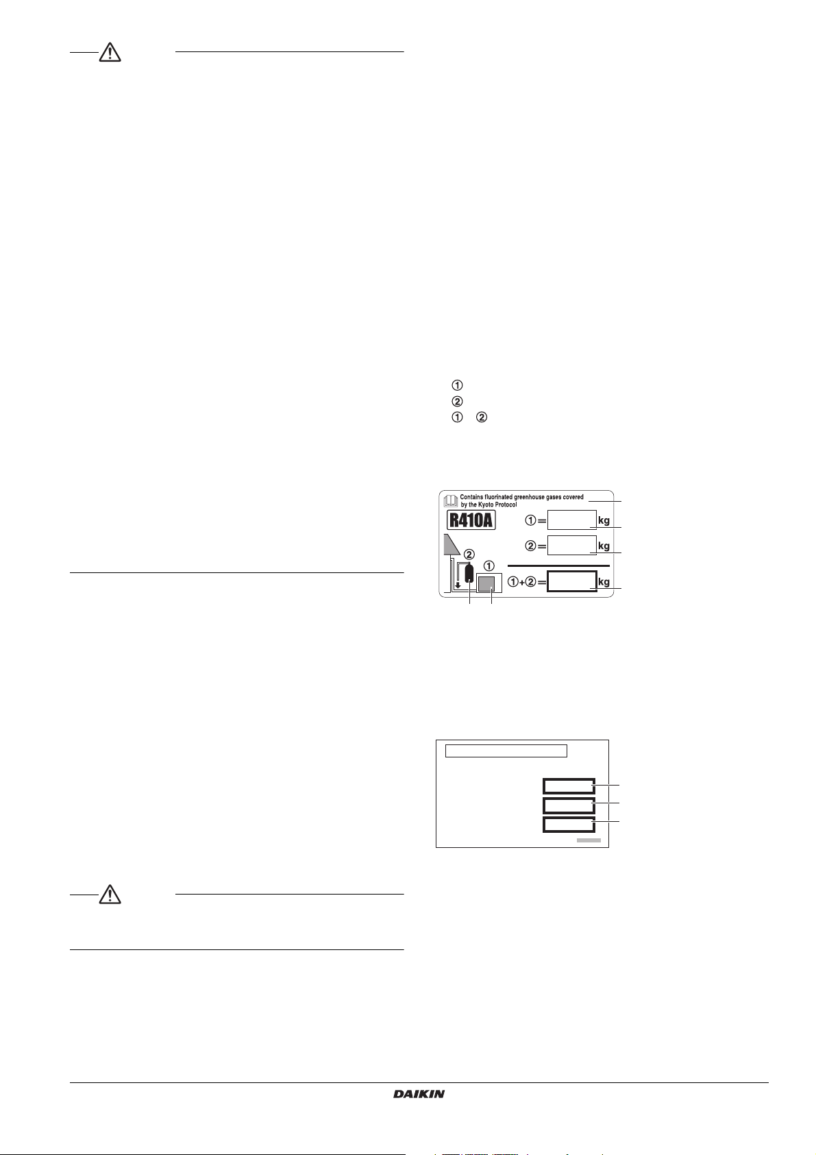
1 factory refrigerant charge
of the product : see unit
name plate
2 additional refrigerant
amount charged in the field
3 total refrigerant charge
4 Contains fluorinated
greenhouse gases covered
by the Kyoto Protocol
5 outdoor unit
6 refrigerant cylinder and
manifold for charging
REF. OIL VOLUME
REF. OIL: DAPHNE FVC68D
TARGET EVAPORATING TEMP.
=
TOTAL REQUIRED.
=
ADDITIONAL OIL.
=
°c
L
L
1
2
3
and insulate the pipe to prevent condensation.
Improper drain piping may result in indoor water leakage and
property damage.
• Install the indoor and outdoor units, power cord and connecting
wires at least 1 meter away from televisions or radios to prevent
picture interference and noise.
(Depending on the incoming signal strength, a distance of 1 meter
may not be sufficient to eliminate noise.)
• Do not install the condensing unit in the following locations:
1. Where there is a high concentration of mineral oil spray or
vapour (e.g. a kitchen).
Plastic parts may deteriorate and cause parts to fall off or water
to leak.
2.
Where corrosive gas, such as sulphurous acid gas, is produced.
Corrosion of copper pipes or brazed parts may occur and cause
refrigerant leakage.
3.
Where there is a machine that generates electromagnetic wave
and where voltage fluctuation often occurs such as a factory.
Control system may malfunction and as a result the unit may
not properly operate.
4. Where flammable gas may leak, where carbon fibre or ignitable
dust is suspensions in the air, or where volatile flammables
such as paint thinner or gasoline are handled.
Operating the unit in such conditions may result in fire.
5. Vehicles, ships, or other places that generate vibration or cause
the condensing unit to move.
The condensing unit may malfunction or cause oxygen
deficiency accidents as a result of refrigerant leakage.
6. Places with excessive voltage fluctuations.
The condensing unit may malfunction.
7. Places where fallen leaves accumulate or weeds grow thick.
8. Places that become small animals’ shelter.
Small animals coming in contact with electrical parts can cause
malfunctions, smoke, or ignition.
• The condensing unit is not intended for use in a potentially
explosive atmosphere.
A.Clean and dry
Strict measures must be taken to keep impurities (including
SUNISO oil and other mineral oils as well as moisture) out of the
system.
B.Tightly sealed
Take care to keep the system tight when installing.
R410A contains no chlorine, does not destroy the ozone layer
and so does not reduce the earth’s protection against harmful
ultraviolet radiation. R410A will contribute only slightly to the
greenhouse effect if released into the atmosphere.
• Since R410A is a mixed refrigerant, the required additional
refrigerant must be charged in its liquid state. If the refrigerant is
charged in a state of gas, its composition changes and the system
will not work properly.
• Be sure to perform refrigerant replenishment.
Refer to "9. CHECKS AFTER WORK COMPLETION" on page 18
and the label of instructions on refrigerant replenishment on the
cover surface of the control box,
Important information regarding the refrigerant used
This product contains fluorinated greenhouse gases covered by the
Kyoto Protocol. Do not vent gases into the atmosphere.
Refrigerant type : R410A
(1)
GWP
value : 1975
(1)
GWP = global warming potential
Please fill in with indelible ink,
the factory refrigerant charge of the product,
the additional refrigerant amount charged in the field and
+ the total refrigerant charge
on the refrigerant charge label supplied with the product.
The filled out label must be adhered in the proximity of the product
charging port (e.g. onto the inside of the service cover).
1-2 Special notice of product
This condensing unit comes under the term “appliances not
accessible to the general public”.
[CLASSIFICATION]
This condensing unit comes under the term “appliances not
accessible to the general public”.
Refer to the connected indoor unit to know the climate class
(EN60335-2-89).
[EMC CHARACTERISTICS]
This system is a class A product. In a domestic environment this
product may cause radio interference in which case the user may be
required to take adequate measures.
[REFRIGERANT]
This System use R410A refrigerant.
The total maximum refrigerant charge of a Multi-ZEAS system must
be less than 100 kg, this to be in accordance with CE requirements
(EN603350-2-40 standard). This means that in case the calculated
total refrigerant charge is equal to or more than 95 kg you must divide
your multiple outdoor system into smaller independent systems, each
containing less than 95 kg refrigerant charge.
This unit is already filled with a certain amount of R410A.
Never open liquid and gas shutoff valve until the step specified in
"9. CHECKS AFTER WORK COMPLETION" on page 18.
• The refrigerant R410A requires that strict precautions be observed
for keeping the system clean, dry and tightly sealed.
Read the chapter "6. REFRIGERANT PIPING" on page 6 carefully
and follow these procedures correctly.
LREQ15+20B7Y1R
Air cooled refrigeration condensing unit
4P360438-1B – 2014.01
[REFRIGERANT OIL]
This system uses DAPHNE FVC68D refrigerant oil. The label below is
attached to the outdoor unit, under the refrigerant label. Fill in the
blanks with indelible ink.
1
Target evaporating temperature
2 Total amount of required refrigerant oil
3 Amount of additional refrigerant oil
[DESIGN PRESSURE]
Since design pressure is 3.8 MPa or 38 bar (for R407C units :
3.3 MPa or 33 bar), the wall thickness of pipes should be more
carefully selected in accordance with the relevant local and national
regulations.
1-3 Disposal requirements
Dismantling of the unit, treatment of the refrigerant, of oil and of other
parts must be done in accordance with relevant local and national
legislation.
Installation manual
2
Page 6
2. BEFORE INSTALLATION
CAUTION
Note
1, 2, 3
4
• When installing the indoor unit, refer to the installation manual
provided for the indoor unit.
• Use the outdoor unit multi-connection piping kit(EKHRQZM) to
split up the gas piping and connect it to the different outdoor units.
• Optional accessories are required for the installation of the
product. Refer to the information on optional accessory.
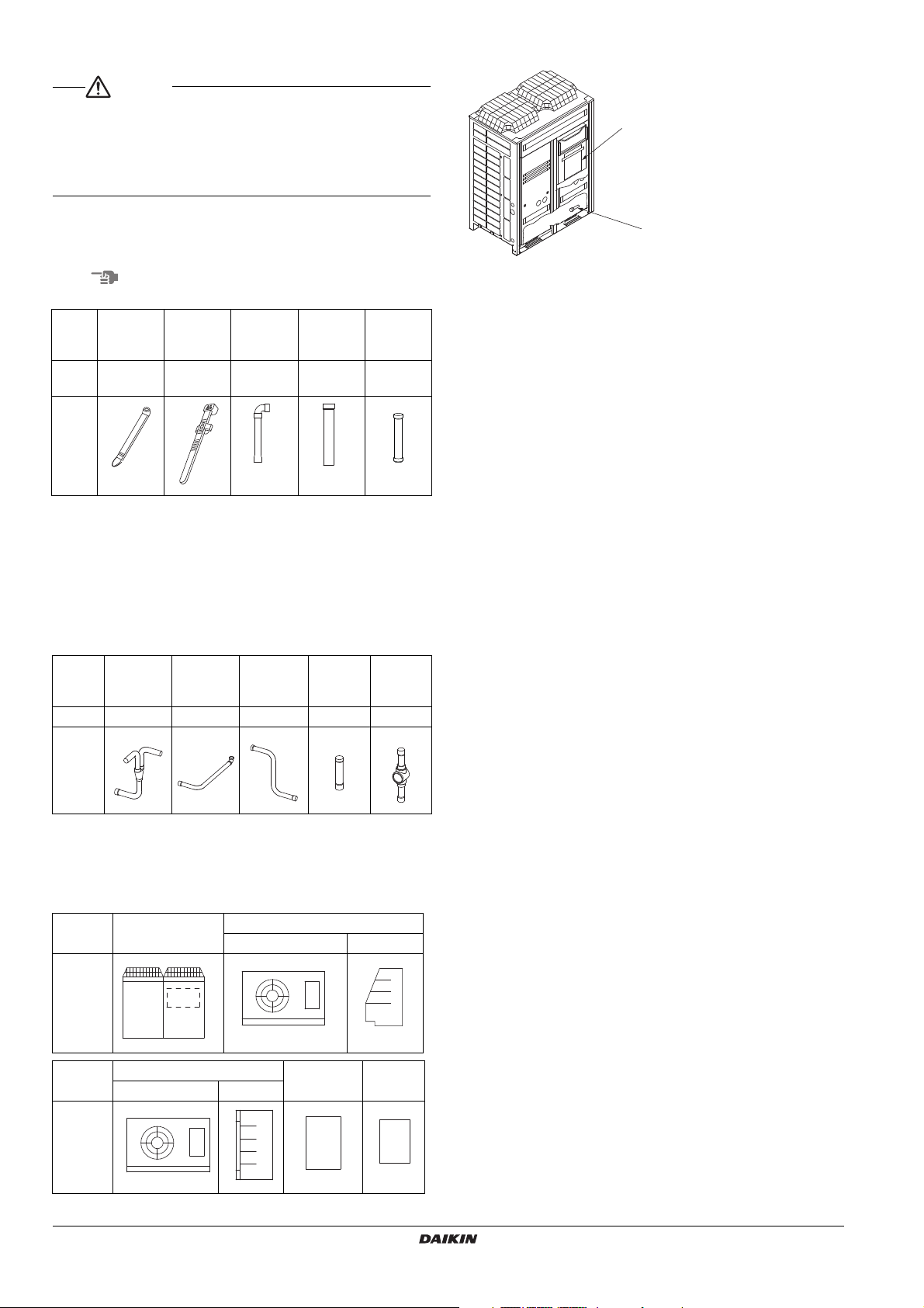
2-1 Standard supplied accessories
The following accessories are included. The storage location of the
accessories is shown in the figure.
Do not throw away any of the accessories until installation is complete.
Liquid side
Name Clamp (1) Clamp (2)
Quan-
Shape
Miscellaneous
• Installation manual
• Operation manual
• Refrigerant label
• Refrigerant oil label
10 pcs. 2 pcs. 1 pc. 1 pc. 1 pc.
tity
Small
accessory
pipe (1)
2-2 Mandatory connection kit
Outdoor unit multi-connection piping kit.
Gas side
Branch pipe
(3)
Name
Quantity
Gas side
Branch pipe
(1)
1 pc. 2 pc. 2 pc. 2 pc. 1 pc.
Gas side
Branch pipe
(2)
Liquid side
accessory
pipe (2)
Gas side
Branch
pipe (4)
Gas side
accessory
pipe (1)
Sight glass
LREQ15, LREQ20
1 Operation manual
2 Installation manual
3 Clamps
4 Accessory pipes (Installed on bottom frame)
2-5 Indoor unit constraints
• Install an R410A mechanical thermostatic expansion valve on
each indoor unit.
• Insulate the feeler block of the mechanical thermostatic expansion
valve.
• Install an R410A solenoid valve (Max. operating differential
pressure of 3.5 MPa [35 bars] or over) on the primary side of the
mechanical thermostatic expansion valve described above for
each indoor unit.
• Install a filter on the primary side of the solenoid valve described
above for each indoor unit. Determine the filter mesh count based
on the size specified by the solenoid valve and mechanical
thermostatic expansion valve being used.
• Route the path to the indoor unit heat exchanger so that the flow of
refrigerant is from top to bottom.
• When installing a number of indoor units, be sure to install them at
the same level.
• Use either off-cycle defrosting or electric heater defrosting as the
defrosting type. Hot-gas defrosting models cannot be used.
• Make sure the total internal volume of indoor units connected to the
condensing units is 80 l or lower.
• Starting from an outdoor temperature of 32°C, the total indoor unit
capacity needs to be 50% or more of the total outdoor unit capacity.
Shape
2-3 Model series
LREQ15-20
2-4 Example of system configuration
Name Outdoor unit
Shape
Name
Shape
Indoor unit
Unit cooler
Showcase
Indoor unit
Unit cooler Showcase
Control panel
(Defrost)
Warning
panel
3. SELECTION OF LOCATION
Select a location for installation that meets the following conditions.
Get the customer’s permission.
1. There is no danger of fire due to leakage of inflammable gas.
2. Select the location of the unit in such a way that neither the
discharged air nor the sound generated by the unit disturb anyone.
3. The foundation is strong enough to support the weight of the unit
and the floor is flat to prevent vibration and noise generation.
4. The piping length between the outdoor unit and the indoor unit may
not exceed the allowable piping length.
(Refer to "6. REFRIGERANT PIPING" on page 6)
5. Locations where the unit’s suction vent and outlet vent do not
generally face the wind.
Wind blowing directly into the suction or outlet vents will interfere
with the unit’s operation.
If necessary, install some kind of obstruction to block the wind.
6. The space around the unit is adequate for servicing and the
minimum space for air inlet and air outlet is available.
(See the "Installation Space Examples" on page 4 for the minimum
space requirements.)
Installation manual
3
Air cooled refrigeration condensing unit
LREQ15+20B7Y1R
4P360438-1B – 2014.01
Page 7
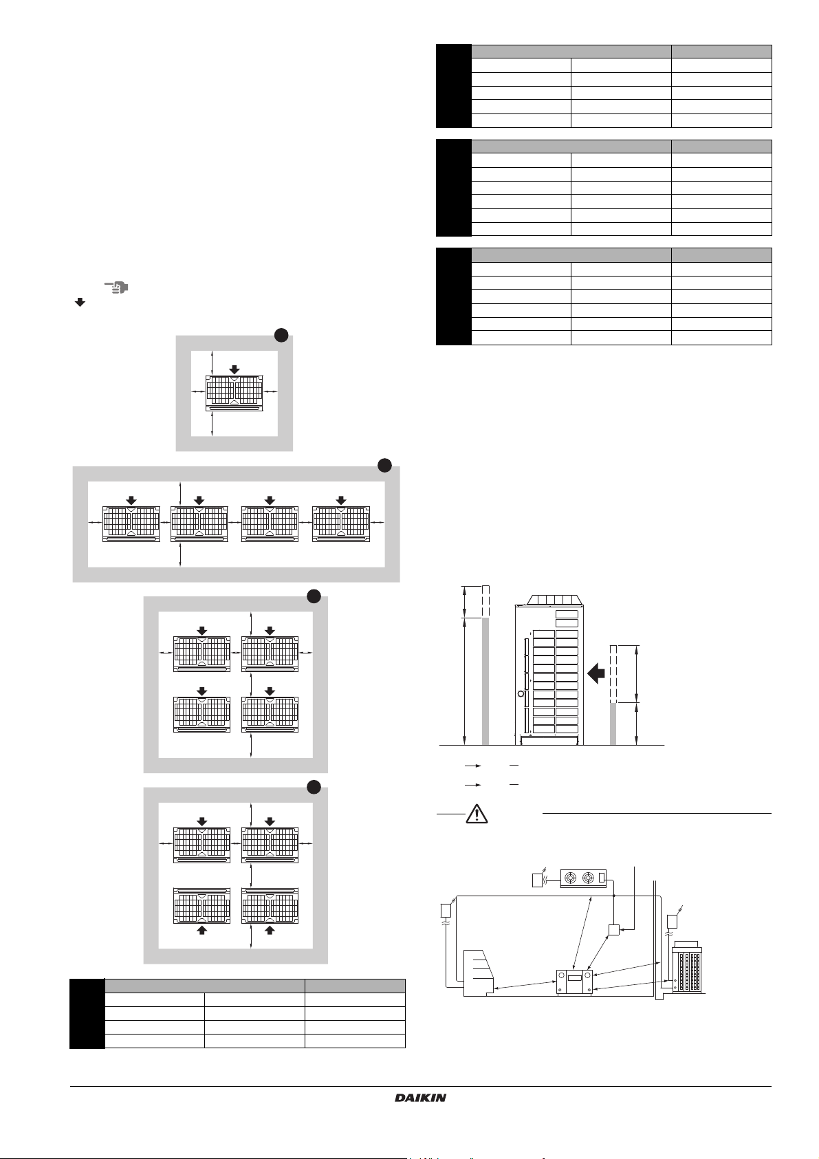
Installation Space Examples
Note
CAUTION
a
b
B
AC
D
d
c
a
b
B
AC
D
d
cee e
a
b
B
AC
D
f
d
e c
1
2
3
a
b
B
AC
D
f
d
e c
4
h
2
h
1
h
1
!EE
h
2
!GG
500
1500
h
1
2
h
2
2
overcurrent breaker
(Earth leakage breaker)
Branch switch,
overcurrent breaker
(Earth leakage breaker)
Control panel
Warning panel
(mm)
• The installation space requirement shown in the following figure is
a reference for cooling operation when the outdoor temperature is
32°C.
If the design outdoor temperature exceeds 32°C or the heat load
exceeds maximum capacity in all the outdoor unit, take an even
large space on the intake shown in the following figure.
• During installation, install the units using the most appropriate of
the patterns shown in the following figure for the location in
question, taking into consideration human traffic and wind.
• If the number of units installed is more than that shown in the
pattern in the following figure, install the units so there are no short
circuits.
• As regards space in front of the unit, consider the space needed for
the local refrigerant piping when installing the units.
• If the work conditions in the following figure do not apply, contact
your dealer or Daikin directly.
The black arrow indicates the suction side of the outdoor units.
A+B+C+D A+B
a≥50 a≥100 a≥200
2
b≥300 b≥100 b≥300
c≥50 c≥100 —
d≥500 d≥500 —
e≥200 e≥300 e≥400
A+B+C+D A+B
a≥50 a≥100 —
b≥300 b≥100 —
3
c≥50 c≥100 —
d≥500 d≥500 —
e≥200 e≥300 —
f≥600 f≥500 —
A+B+C+D A+B
a≥50 a≥100 —
b≥300 b≥100 —
4
c≥50 c≥100 —
d≥300 d≥100 —
e≥200 e≥300 —
f≥500 f≥500 —
NOTE) For patterns 1 and 2
• Wall height for front side no higher than 1500 mm.
• Wall height on the suction side no higher than 500 mm.
• Wall height for sides – no limit
• Make sure each unit is installed level.
• Install the slave unit adjacent to the master unit.
• Make sure the slave unit faces the same direction as the master
unit.
• Provide enough space for maintaining and servicing the units.
• Provide adequate space for the air in- and outlets.
• Make sure the total length of the gas piping between the
outdoor unit and the outdoor unit multi-connection piping kit is
≤10 m.
• If the height is exceeded the above, calculate h1 and h2 shown
in the figure below, and add h1/2 to the service space of front
side and h2/2 to the service space of suction side.
Branch switch,
1
A+B+C+D A+B
a≥50 a≥100 a≥200
b≥300 b≥100 b≥300
c≥50 c≥100
d≥500 d≥500
Showcase
LREQ15+20B7Y1R
Air cooled refrigeration condensing unit
4P360438-1B – 2014.01
Installation manual
4
Page 8
1. An inverter condensing unit may cause electronic noise generated
1240560
1680
1290
765 1240560 560
1290
33
2
1
a
cd
ef
b
*1
g
*1
*2
*1
A
B
C
7000
3000
1500 1500
ab
*1
*1
*3
c
1300
1300
abcd
baba
c c
from AM broadcasting. Examine where to install the main
condensing unit and electric wires, keeping proper distances away
from stereo equipment, personal computers, etc.
Particularly for locations with weak reception, ensure there is a
distance of at least 3 meters for indoor remote controllers, place
power wiring and transmission wiring in conduits, and ground the
conduits.
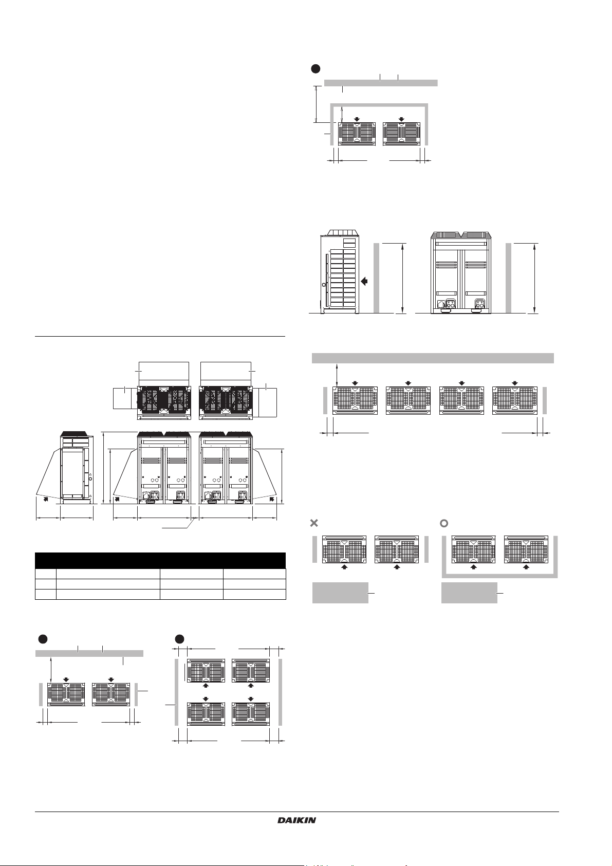
2. When installing in a locations where there is heavy snowfall,
implement the following snow measures.
• Ensure the base is high enough that intakes are not clogged by
snow.
• Mount a snowbreak hood (optional accessory)
• Remove the rear intake grille to prevent snow from
accumulating on the fins.
3. If condensate may drip on downstairs (or walkway) depending on
the floor condition, take a measure such as the installation of
central drain pan kit (sold separately).
4. The refrigerant R410A itself is nontoxic, nonflammable and is safe.
If the refrigerant should leak however, its concentration may
exceed the allowable limit depending on room size. Due to this it
could be necessary to take measures against leakage.
See “Engineering Data” for details.
5. If the outdoor units are installed in areas with heavy snowfall, the
installation of a snowbreak hood is required. This is available as an
optional accessory. If the units are installed in a location where the
ambient temperature can drop below –10°C, install a windbreak
board or a snowbreak hood.
1. Snowbreak hood installation
f Slave unit 2
g Wall height unrestricted
In case a suction-side board is required:
a Master unit
b Slave unit
c Wall height unrestricted
Notes:
*1 Board and wall height: 1300 mm or more.
*2 If the outdoor units are installed in rows, install side boards on both
sides of the installation.
200
Required parts:
Snowbreak hood
Option names
Required amount
1 Right side air inlet KPS26C504R 1
2 Left side air inlet KPS26C504L 1
3 Back side air inlet KPS26C504B 2
2. Windbreak board installation
In case no suction-side board is required:
a Master unit 1
b Slave unit 1
c Master unit 2
d Slave unit 2
*3 If there is no wall opposite the suction side of each outdoor unit,
install a suction-side board covering all outdoor units.
a Master unit 1
b Slave unit 1
c Wall height unrestricted
*4 For the installation space around the outdoor units, see
"3. SELECTION OF LOCATION" on page 3.
a Master unit
b Slave unit
c Master unit 1
d Slave unit 1
e Master unit 2
Installation manual
5
Air cooled refrigeration condensing unit
LREQ15+20B7Y1R
4P360438-1B – 2014.01
Page 9
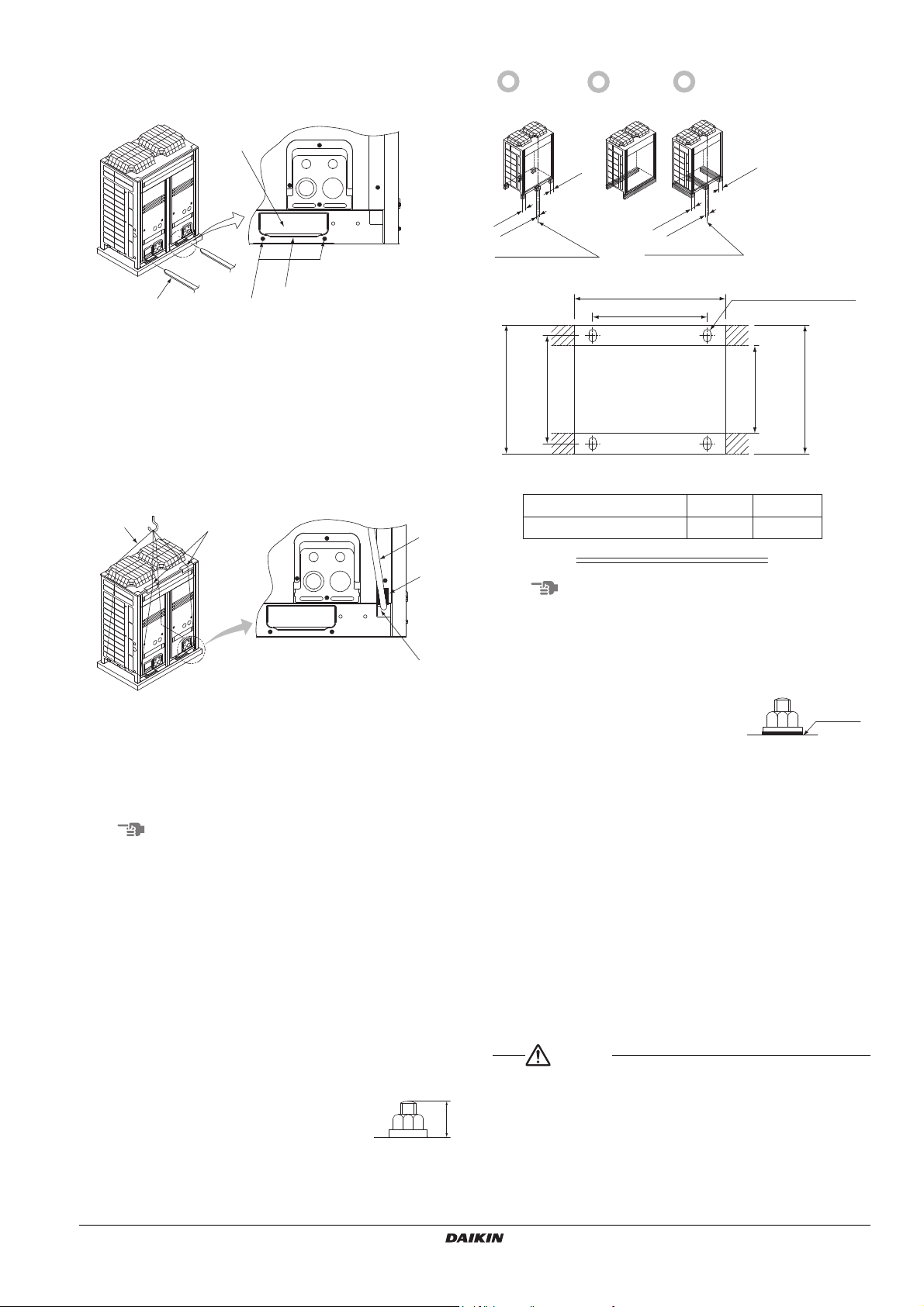
4. HANDLING THE UNIT
Note
Note
CAUTION
1
2
4
3
1
2
3
4
5
20
Independent
foundation
Beam
foundation
(horizontal)
Beam
foundation
(vertical)
Center of the product
Center of the product
A
B
729
765
(Depth of product)
631
(Inner dimension
of the base)
765 or more
(Outer dimension
of the base)
Base width and base bolt positions
Foundation bolt point
(4-15 × 22.5)
LREQ15, LREQ20 1240 1102
Model A B
(Unit : mm)
washers
1. Decide on the transportation route.
2. If a forklift is to be used, pass the forklift arms through the large
openings on the bottom of the unit.
1 Opening (large)
2 Fork
3 Fixed screws of transportation clasp
4 Transportation clasp (yellow)
If hanging the unit, use a cloth sling to prevent damaging the unit.
Keeping the following points in mind, hang the unit following the
procedure shown in the following figure.
• Use a sling sufficiently strong to hold the mass of the unit.
• Use 2 belts of at least 8m long.
• Place extra cloth in the locations where the casing comes in
contact with the sling to prevent damage.
•
Hoist the unit making sure it is being lifted at its center of gravity.
Base form
1 Belt sling
2 Patch cloth
3 Belt sling
4 Patch cloth
5 Opening (small)
3. After installation, remove the transportation clasp (yellow) attached
to the large openings.
Apply a filler cloth on a fork to prevent coating of the bottom frame from
coming off and rust from occurring when bringing in the unit with anticorrosion treatment type using a forklift.
5. PLACING THE UNIT
• Make sure the unit is installed level on a sufficiently strong base to
prevent vibration and noise.
• The base should be bigger around than the width of the unit’s legs
(66 mm), and should support the unit.
If protective rubber is to be attached, attach it to the whole face of
the base.
• The height of the base should be at least 150 mm from the floor.
• Secure the unit to its base using foundation bolts. (Use four
commercially available M12-type foundation bolts, nuts, and
washers.)
• The foundation bolts should be inserted 20 mm.
LREQ15+20B7Y1R
Air cooled refrigeration condensing unit
4P360438-1B – 2014.01
• When installing on a roof, make sure the roof floor is strong enough
and be sure to water-proof all work.
• Make sure the area around the machine drains properly by setting
up drainage grooves around the foundation.
Drain water is sometimes discharged from the outdoor unit when it
is running.
• If the condensing unit is of brine
damage resistant or heavy brine
damage resistant type, use nuts
provided with resin washers to secure
the product to the foundation bolts (see
the illustration on the right-hand side).
The rustproof effect of the nut will be lost if the coatings on the
tightening portions of the nuts come off.
Resin
6. REFRIGERANT PIPING
To Piping Work Contractors
• Never open the shutoff valve until the steps specified in "7. FIELD
WIRING" on page 13 and "8-3 Checking of device and installation
conditions" on page 18 of piping.
• Do not use flux at the time of brazing and connecting refrigerant
pipes. Use phosphorous copper brazing filler metal (BCuP-2),
which does not require flux. Chlorine-based flux causes piping
corrosion. Furthermore, if fluoride is contained, the flux will have
adverse influences on the refrigerant piping line, such as the
deterioration of refrigerating machine oil.
• All field piping must be installed by a licensed refrigeration
technician and must comply with relevant local and national
regulations.
[Precautions for reuse of existing refrigerant piping/heat
exchangers]
Keep the following points in mind for the reuse of existing
refrigerant piping / heat exchangers.
A malfunction may result if there is deficiency.
Installation manual
6
Page 10

• Do not use the existing piping in the following cases. Perform new
Note
d1
e
B
d2
C
c
D1
F
E
f
D2
A
b
a
H
G1g1 g2 G2
12
3
5
6
4
piping instead.
• The piping is different in size.
• The strength of the piping is insufficient.
• The compressor of the condensing unit previously used caused a
malfunction.
An adverse influence of residual substances, such as the oxidation
of refrigerant oil and the generation of scale, is considered.
• If the indoor unit or outdoor unit is disconnected from the piping for
a long time.
The intrusion of water and dust into the piping is considered.
• The copper pipe is corroded.
• The refrigerant of the condensing unit previously used was other
than R410A (e.g., R404A / R507 or R407C).
The contamination of the refrigerant with heterogeneity is
considered.
• If there are welded connections midway on the local piping, make
• Be sure to insulate the connection piping.
The liquid and gas pipe temperatures are as follows:
Liquid pipe arrival minimum temperature: 0°C
Gas pipe arrival minimum temperature: –45°C
In the case of thickness insufficiency, add additional insulation
material or renew the existing insulation material.
• Renew the insulation material if the insulation material is degraded.
Keep the following points in mind for the reuse of existing heat
exchangers
• Units with insufficient design pressure (since this product is an
R410A unit) require a lower-stage design pressure of 2.5 MPa
[25 bars].
• Units for which the path to the heat exchanger has been routed so
that the flow of refrigerant is from bottom to top
• Units with copper tubing or fan corrosion
• Units that may be contaminated with foreign matter such as
rubbish or other dirt
gas leakage checks on the welded connections.
6-1 Selection of piping material
•
Make sure that the inner side and outer side of the piping used is clean and free of contaminants, such as sulphur, oxide, dust, chips, oil and fat, and water.
It is desirable that the maximum oil adhesion in the piping is 30 mg per 10 m.
• Use the following type of refrigerant piping.
Material: Seamless phosphorus deoxidized copper tube (C1220T-O for a maximum outer diameter of 15.9 mm and C1220T-1/2H for a minimum
Refrigerant piping size and wall thickness: Decide the size and thickness from the following table.
(This product uses R410A. The withstand pressure of O type may be insufficient if it is used for piping with a minimum diameter of
19.1 mm. Therefore, be sure to use 1/2 H type with a minimum thickness of 1.0 mm.
If O type is used for piping with a minimum diameter of 19.1 mm, a minimum thickness of 1.2 mm will be required. In that case, be sure
to perform the blazing of each joint.)
• Be sure to perform piping work within the range specified in the
following tables.
Refrigerant piping length
Max. permissible one-way piping length
(equivalent length)
Total length of the gas pipes between the
outdoor units and the outdoor unit
multi-connection piping kit
(g=g1+g2)
Max. branch piping length (actual length) b + c + d ≤30 m (d is d1 or d2 whichever is longer)
Max. difference in
height between
indoor and outdoor
units
A trap is required at 5 m intervals from the outdoor unit.
Make sure the pressure drop is as small as possible.
outer diameter of 19.1 mm)
unit below outdoor
unit
unit above outdoor
unit
Te ≥–20°C
a + b + c + d+g2 ≤130 m
(d is d1 or d2 whichever is longer)
Te <–20°C
a + b + c + d+g2 <100 m
(d is d1 or d2 whichever is longer)
g≤10 m
g1≤g2
H ≤35 m (Note)
H ≤10 m
1 Master unit
2 Slave unit
3 Outdoor unit multi-connection
piping kit
4 Gas piping
5 Showcase
6 Blower coil
Refrigerant piping size (Unit: mm)
Outdoor unit side Piping size
Liquid pipe Gas pipe
Outdoor unit
Ø12.7 x 0.8 (O type) Ø34.9 x 1.2 (1/2 H type or H type)
multi-connection piping
kit (G1, G2, g1, g2)
Main piping (A,a) Ø19.1 x 1.0 (1/2 H type or H type) Ø41.3 x 1.45 (1/2 H type or H type)
Installation manual
7
Air cooled refrigeration condensing unit
LREQ15+20B7Y1R
4P360438-1B – 2014.01
Page 11

Note
Note
CAUTION
Piping between
Refrigerant pipe
Regulator
Handy valve
Taping
Nitrogen
Nitrogen
Location to
be brazed
Liquid side shutoff valve
(provided with service port)
Gas side shutoff valve
(provided with service port)
* Maintenance shutoff valve
(Do not operate)
(Do not operate)
* Maintenance shutoff valve
branching areas (B, b,
C, c)
Select the piping from the following table in accordance with the total capacity of indoor units connected
downstream
Total capacity of indoor units after branching Liquid pipe size
less than 4.0 kW Ø6.4 x 0.8 (O type)
4.0 kW over and less than 14.0 kW Ø9.5 x 0.8 (O type)
14.0 kW over and less than 30.0 kW Ø12.7 x 0.8 (O type)
30.0 kW over and less than 50.0 kW Ø15.9 x 1.0 (O type)
50.0 kW or over Ø19.1 x 1.0 (O type)
Total capacity of indoor units after branching
Medium temperature
(–20°C or more)
less than 1.0 kW — Ø9.5 x 0.8 (O type)
1.0 kW over and less than 6.0 kW less than 1.5 kW Ø12.7 x 0.8 (O type)
6.0 kW over and less than 9.9 kW 1.5 kW over and less than 2.5 kW Ø15.9 x 1.0 (O type)
9.9 kW over and less than 14.5 kW 2.5 kW over and less than 3.8 kW Ø19.1 x 1.0 (O type)
14.5 kW over and less than 25.0 kW 3.8 kW over and less than 5.9 kW Ø22.2 x 1.0
25.0 kW over and less than 31.0 kW 5.9 kW over and less than 9.8 kW Ø28.6 x 1.0
31.0 kW or over and less than 40.0 kW 9.8 kW over and less than 19.0 kW Ø34.9 x 1.2
40.0 kW or over 19.0 kW or over Ø41.3 x 1.45
No size after branching can exceed the size of any upstream piping.
Low temperature
(–20°C or less)
Gas pipe size
(1/2 H or H type)
(1/2 H or H type)
(1/2 H or H type)
(1/2 H or H type)
Piping between
branching areas and
each unit
Adjust the size of the piping so that it will coincide with the size of piping connecting to the indoor unit
6-2 Protection against contamination when
installing pipes
Protect the piping to prevent moisture, dirt, dust, etc. from entering the
piping.
Place Installation period Protection method
Outdoor
Indoor Regardless of the period
Exercise special caution to prevent dirt or dust when passing piping
through holes in walls and when passing pipe edges to the exterior.
More than a month Pinch the pipe
Less than a month
Pinch or tape the pipe
6-3 Pipe connection
•
Be sure to perform nitrogen permutation or nitrogen blow when brazing.
6-4 Connecting the refrigerant piping
• In addition to gas and liquid shutoff valves, this unit has a
maintenance shutoff valve (see diagram below).
• Do not operate the maintenance shutoff valve*.
(The factory setting for the maintenance shutoff valve is “open.”
During operation, always leave this valve in the open position.
Operating the unit with the valve in the closed position may cause
the compressor to fail.)
Brazing without performing nitrogen permutation or nitrogen blow
into the piping will create large quantities of oxidized film on the
inside of the pipes, adversely affecting valves and compressors in
the refrigerating system and preventing normal operation.
• The pressure regulator for the nitrogen released when doing the
brazing should be set to 0.02 MPa (about 0.2 kg/cm
feel a slight breeze on your cheek).
Do not use anti-oxidants when brazing the pipe joints.
Residue can clog pipes and break equipment.
LREQ15+20B7Y1R
Air cooled refrigeration condensing unit
4P360438-1B – 2014.01
2
:Enough to
Installation manual
8
Page 12

1. Directions to bring out the pipes
WARNING
CAUTION
CAUTION
CAUTION
CAUTION
CAUTION
Right-side connection
Front connection
Left-side connection
Concave section
(4 places)
CAUTION
AB
2
1
1
3
2
The local interunit piping can be connected either forward or to the
sides (taken out through the bottom) as shown in the following
figure.
When passing out through the bottom, use the knock hole in the
bottom frame.
Never remove the pinched piping by brazing.
8 Wait until all oil is dripped out in case the recovery was not
complete, and only then proceed with connection of the field
piping.
Precautions when knocking out knock holes
• Open knock hole in the base frame by drilling the 4 concave around
it with a 6 mm bit.
Knock hole
• Be sure to avoid damaging the casing
• After knocking out the holes, we recommend you remove any burrs
and paint them using the repair paint to prevent rusting.
• When passing electrical wiring through the knock holes, protect the
wiring with a conduit or bushings, making sure not to damage the
wiring.
Drill
2. Removing Pinch Piping
Never remove the pinched piping by brazing.
Failure to observe the instructions in procedure below properly may
result in property damage or personal injury, which may be serious
depending on the circumstances.
Use the following procedure to remove the pinched piping:
1 Remove the valve lid and make sure that the stop
valves are fully closed.
1 Service port
2Stop valve
3 Point of pipe cutting just above brazing point or above marking
A Pinched piping
B Pinched piping
Precautions when connecting field piping.
• Perform brazing at the gas stop valve before brazing at the liquid
stop valve.
• Add brazing material as shown in the figure.
• Be sure to use the supplied accessory pipes when carrying out
piping work in the field.
• Be sure that the field installed piping does not touch other pipes,
the bottom panel or side panel. Especially for the bottom and side
connection, be sure to protect the piping with suitable insulation, to
prevent it from coming into contact with the casing.
2 Connect a charge hose to service ports of all stop valves.
3 Recover gas and oil from the pinched piping by using a recovery
unit.
Do not vent gases into the atmosphere.
4 When all gas and oil is recovered from the pinched piping,
disconnect the charge hose and close the service ports.
5 In case the pinched piping lower part looks like detail in the
figure below, follow instructions as per procedure steps 7+8.
In case the pinched piping lower part looks like detail in the
figure below, follow instructions as per procedure steps 6+7+8.
6 Cut off the lower part of the smaller pinched piping with an
appropriate tool (e.g. a pipe cutter, a pair of nippers, ...) so
that a cross-section is open, allowing remaining oil to drip
out in case the recovery was not complete.
Wait until all oil is dripped out.
7 Cut the pinched piping off with a pipe cutter just above the brazing
point or just above the marking in case there is no brazing point.
Installation manual
9
Operation Method of Shutoff Valves
Follow the instructions below when operating each shutoff valve.
• Do not open the shutoff valve until the steps specified in
“8-3 Checking of device and installation conditions” is
completed.
Do not leave the shutoff valve opened without turning the power
on, otherwise refrigerant may be condensed in the compressor and
the insulation of the main power supply circuit may be degraded.
• Be sure to use an exclusive tool to handle the shutoff valve. The
shutoff valve is not of back sheet type. Excessive force imposed
may break the valve.
• Use a charge hose when using the service port.
• Make sure that there is no refrigerant gas leakage after the valve
cover and cap are securely tightened.
Tightening torque
Check with the following table the sizes of shutoff valves incorporated
by each model and the tightening torque values of the respective
shutoff valves.
Air cooled refrigeration condensing unit
LREQ15+20B7Y1R
4P360438-1B – 2014.01
Page 13

Shutoff valve sizes
CAUTION
CAUTION
CAUTION
Valve cover
Hexagon hole
Shaft
Sealing part
Screw thread
Apply a screw lock agent
Sealing part
Not apply a screw lock agent
Shutoff valve
Part of mounting the
valve cover.
Valve cover
Sealing part
Not apply a screw
lock agent
Screw thread
Apply a screw lock
agent
Cap
1
2
3
3
1
Liquid side shutoff
valve
Gas side shutoff
valve
LREQ
LREQ15-20
Ø12.7
Ø31.8
Service port
Handling Precautions for Service Port
• Work on the service port with a charge hose provided with a
pushing rod.
• At the time of mounting the cap, apply a screw lock agent to the
screw thread.
• Do not apply a screw lock agent (for flare nut use) to the sealing
part.
•
Be sure to tighten the cap securely after the work. Refer to
"Operation Method of Shutoff Valves" on page 9 for the tightening
torque of the cap.
Shutoff
valve sizes
Ø12.7 8.1~9.9
Ø31.8 26.5~29.4
Opening method
1. Remove the valve cover and turn the shaft anticlockwise with a
hexagon wrench.
2. Turn the shaft until the shaft stops.
3. Tighten the valve cover securely. Refer to the above table for the
tightening torque according to the size.
Closing method
1. Remove the valve cover and turn the shaft clockwise with a hexagon wrench.
2. Tighten the shaft until the shaft comes in contact with the sealing
part of the valve.
3. Tighten the valve cover securely. Refer to the above table for the
tightening torque according to the size.
Handling precautions for valve cover
• Be careful not to damage the sealing part.
• At the time of mounting the valve cover, apply a screw lock agent to
the screw thread.
• Do not apply a screw lock agent (for flare nut use) to the sealing
part.
• Be sure to tighten the valve cover securely after operating the
valve. Refer to "Operation Method of Shutoff Valves" on page 9 for
the tightening torque of the valve.
Tightening torque N•m (closes clockwise)
Shaft (valve body) Valve cover Service port
Hexagon
wrench: 4mm
Hexagon
wrench: 10 mm
18.0~22.0
11.5~13.9
44.1~53.9
Apply a screw lock agent to the valve cover mount and the screw
thread of the service port.
Otherwise, dew condensation water will intrude inside and freeze.
Therefore, refrigerant gas leakage or a compressor malfunction may
result from the cap deformation or damage.
3. Connecting refrigerant piping to outdoor units
Use the outdoor unit multi-connection piping kit (EKHRQZM) to split
up the gas piping and connect it to the different outdoor units.
• Only use the dedicated outdoor unit multi-connection piping kit
(EKHRQZM).
• Failire to correctly install the kit may lead to compressor damage.
• When brazing, make sure there are no flammable materials
around.
• Make sure the gas piping slants downward toward the outdoor
units.
If connected to the front
1. Connect gas side branch pipes(3) to gas side branch pipe (1).
These pipes are supplied with the outdoor unit multi-connection
piping kit.
LREQ15+20B7Y1R
Air cooled refrigeration condensing unit
4P360438-1B – 2014.01
1 Gas side branch pipe (3)
2 Gas side branch pipe (1)
3 Brazing
When installing gas side branch pipe (1), take the following into
account:
• Do not tilt more than 10°.
• Make sure the maximum height difference with the outdoor unit is
≤3m.
• Install it horizontally.
Installation manual
10
Page 14

2. Connect gas side branch pipes(2) to the gas side shutoff valves.
CAUTION
CAUTION
1
2
2
1
3 3
1
2
4
1
2
3
3
3
1
2
A
A
A
2
1
3
1
1
4
3
3
4
4
4
2
2
1 2
4
13 2
4
The pipes are supplied with the outdoor unit multi-connection
piping kit.
1 Gas side branch pipe (2)
2 Gas side shutoff valve
3 Brazing
3. Connect gas side branch pipes (3) to gas side branch pipes (2) by
way of field-supplied branch pipes.
When connected at the lateral side (bottom)
• Only use the dedictated outdoor unit multi-connection piping kit
(EKHRQZM).
• When brazing, make sure there are no flammable materials
around.
1. Connect gas side accessory pipes (1) to field-supplied branch
pipes. Gas side accessory pipes (1) are supplied with the outdoor
units.
2. Connect gas side accessory pipes (1) to the gas side shutoff
valves.
1 Gas side branch pipe (3)
2 Branch pipe (field supply)
3 Gas side branch pipe (2)
4 Brazing
4. Connect gas side branch pipe (1) to the main gas pipe. The main
gas pipe is field-supplied.
1 Main gas pipe (field supply)
2 Gas side branch pipe (1)
3 Brazing
5. Connect liquid side accessory pipes (1) to the liquid side shutoff
valves. Liquid side accessory pipes (1) are supplied with the
outdoor unit.
1 Liquid side shutoff valve
2 Brazing
3 Liquid side accessory pipe (1)
Installation manual
11
1 Gas side accessory pipe (1)
2 Branch pipe (field supply)
3 Gas side shutoff valve
4 Brazing
3. Connect the field-supplied branch pipes to gas side branch pipe (1)
by way of gas side branch pipes (4). Gas side branch pipe (1) and
gas side branch pipes (4) are supplied with the outdoor unit
multi-connection piping kit.
1 Gas side branch pipe (4)
2 Branch pipe (field supply)
3 Gas side branch pipe (1)
4 Brazing
When installing gas side branch pipe (1), take the following into
account:
• Do not tilt more than 10°.
• Make sure the maximum height difference with the outdoor unit is
≤3m.
• Install it horizontally.
Air cooled refrigeration condensing unit
LREQ15+20B7Y1R
4P360438-1B – 2014.01
Page 15

4. Connect gas side branch pipe (1) to the main gas pipe. The main
CAUTION
CAUTION
1
2 3
A
A
1
2
3
4
ba
surface
±30° or less
A-arrow view
Y-joint
gas pipe is field-supplied.
1 Gas side branch pipe (1)
2 Main gas pipe (field supply)
3 Brazing
5. Connect liquid side accessory pipes (2) to the liquid side shutoff
valves. Liquid side accessory pipes (2) are supplied with the
outdoor units.
A
Dryer installation
Select a dryer from the following chart:
Model Required dryer core (recommended type)
LREQ15-20 550 g (100% molecular sieve equivalent)
(48-DM: Danfoss made)
• Install the dryer in a horizontal orientation wherever possible.
• Install the dryer as close to the outdoor unit as possible.
• Remove the dryer cap immediately before brazing (to prevent
absorption of airborne moisture).
• Follow instructions in the dryer instruction manual concerning dryer
brazing.
• Repair any burning of dryer paint that occurs during dryer
brazing. Contact the manufacturer for more information about
paint for repair use.
• Flow direction is specified for some type of the dryer.
Set the flow direction according to the operation manual of the
dryer.
• Install the dryer on the main liquid pipe.
Sight glass installation
• The sight glass is supplied with the outdoor unit
mult-connection piping kit.
• Install the sight glass between the dryer and the indoor unit, as
close to the outdoor unit as possible.
• Make sure the sight glass is comfortably accessible.
• Install the sight glass on the main liquid pipe.
• During brazing, use a wet cloth to cool down the glass portion of
the sight glass.
1 Liquid side shutoff valve
2 Liquid side accessory pipe (2)
3 Branch pipe (field supply)
4 Brazing
• Check that the on-site piping does not come in contact with other
piping, the bottom frame, or side plate of the product.
Field installation items
• This product requires that a dryer and a sight glass be installed on
liquid piping on site. (Operating the unit without a dryer installed
may result in equipment failure.)
• Only install the dryer and the sight glass after the other field piping
has been installed .
• Operating the units without a sight glass installed makes it
impossible to check the state of the refrigerant.
• When brazing, make sure there are no flammable materials
around.
a Sight glass
b Dryer
Precautions for Piping
Perform piping branching with the following conditions kept in mind.
• At the time of branching the liquid piping, use a T-joint or Y-joint
and branch it horizontally. This will prevent an uneven flow of
refrigerant.
• At the time of branching gas piping, use a T-joint and branch it so
that the branched piping will be located above the main piping (see
the illustration below). This will prevent the stay of refrigerant oil in
the indoor unit not in operation.
• Use a Y-joint for the liquid refrigerant branch and have the piping
branch horizontally.
Horizontal
A
LREQ15+20B7Y1R
Air cooled refrigeration condensing unit
4P360438-1B – 2014.01
Installation manual
12
Page 16

• Use a T-joint for the gas refrigerant branch and connect from the
CAUTION
T-joint
Main piping
Indoor unit side
Outdoor unit side
Branch piping
Make the piping
slant downward
Branch piping
Make the piping
slant downward
Main piping
Make the piping
slant downward
T-joint
(not more than 1mA, 12VDC).
Capacity for operation output run output : 0.5A or less at AC 220 to 240V.
2
X3M
1
X1M(A1P)
Q1
X1M(A1P)
Q2Q2
Q1
L3
C
L2
X1M
L1
A
X1M
N
B
L1
L2
X1M(A5P)
W1
N
L3
Ry1
Ry1
P1 P2RC1C
2
7
9
3
1
10
11
5
6
8
13
4
S1T
Y1S
top of the main piping.
• Make sure that the horizontal portion of the gas piping slants
downward to the outdoor unit (see the illustration above).
• If the outdoor unit is located above, make a trap on the gas pipe at
5 m intervals from outdoor unit. This will ensure the smooth
returning of oil in the piping slanting upward.
Gas piping
• Make sure that the horizontal run of the gas piping slants
downward to the outdoor unit.
• In order to prevent oil retention, do not make a trap in the horizontal
run of the gas piping.
7. FIELD WIRING
To electric engineering contractors
• Be sure to install an earth leakage breaker. The product
incorporates inverter equipment. In order to prevent the
malfunctioning of the earth leakage breaker, make sure that the
earth leakage breaker withstands harmonic interference.
• Do not operate the condensing unit until refrigerant piping work is
completed, or otherwise the compressor will malfunction.
• Do not remove any electrical components such as thermistors or
sensors when connecting power supply wires or transmission
wires. The compressor may malfunction if the condensing unit is
operated with such electrical components removed.
• Be sure to install an earth leakage circuit breaker.
This unit uses an inverter, so install the earth leakage circuit
breaker that be capable of handling high harmonics in order to
prevent malfunctioning of the earth leakage circuit breaker itself.
• Earth leakage circuit breaker which are especially for protecting
ground-faults should be used in conjunction with main switch or
fuse for use with wiring.
• Electrical wiring must be done in accordance with the wiring
diagrams and the description herein.
• Do not operate until refrigerant piping work is completed.
(If operated before complete the piping work, the compressor may
be broken down.)
• Never remove thermistor, sensor or etc. when connecting power
wiring and transmission wiring.
(If operated with thermistor, sensor or etc. removed, the
compressor may be broken down.)
• This product have reversed phase protection detector that only
works when the power is turned on. If there exists black out or the
power goes on and off which the product is operating, attach a
reversed phase protection circuit. Running the product in reversed
phase may break the compressor and other parts.
• Attach the power wire securely. Introducing power with a missing
N-phase or with a mistaken N-phase will break the unit.
• Never connect the power supply in reversed phase.
The unit can not operate normally in reversed phase.
If you connect in reversed phase, replace two of the three phases.
• Make sure the electrical unbalance ratio is no greater than 2%. If it
is larger than this, the unit’s lifespan will be reduced.
If the ratio exceeds 4%, the unit will shut down and an malfunction
code will be displayed on the indoor remote controller.
• Connect the wire securely using designated wire and fix it with
attached clamp without applying external pressure on the terminal
parts (terminal for power wiring, terminal for transmission wiring
and earth terminal).
• Install a switch that allows you to switch OFF all poles from the
main power supply.
7-1 Example of wiring entire system
Ry1 Relay
S1T Thermostat for inner temperature adjustment
Y1S Solenoid valve
12
• All field wiring and components must be installed by a licensed
electrician and must comply with relevant local and national
regulations.
• Be sure to use a dedicated power circuit. Never use a power supply
shared by another appliance.
• Never install a phase advancing capacitor. As this unit is equipped
with an inverter, installing a phase advancing capacitor will not only
deteriorate power factor improvement effect, but also may cause
capacitor abnormal heating accident due to high-frequency waves.
• Only proceed with wiring work after blocking off all power.
• Always ground wires in accordance with relevant local and national
regulations.
• This machine includes an inverter device. Connect earth and leave
charge to eliminate the impact on other devices by reducing noise
generated from the inverter device and to prevent leaked current
from being charged in the outer hull of the product.
• Do not connect the ground wire to gas pipes, sewage pipes,
lightning rods, or telephone ground wires.
Gas pipes: can explode or catch fire if there is a gas leak.
Sewage pipes: no grounding effect is possible if hard plastic
piping is used.
Telephone ground wires and lightning rods: dangerous when
struck by lightning due to abnormal rise in electrical potential in the
grounding.
Installation manual
13
Note: 1. In case of used remote switch, use dry contact for microcurrent
Note: 2. Total capacity for caution, warning : 0.5A or less at AC 220 to 240V.
1 3 phase 50 Hz 380~415 V
Earth leakage circuit breaker (high-frequency type) (for earth
fault, overload, and short-circuit protection)
2 Master units
3 Slave unit
Air cooled refrigeration condensing unit
LREQ15+20B7Y1R
4P360438-1B – 2014.01
Page 17

4 Remote switch (See Note 2)
Note
Note
Through-hole cover
Cut the shaded area
(Rear side of control
box lid)
Conduit
Piping outlet
High-voltage wiring
Low-voltage wiring
Knockout hole
(For low-voltage wiring)
Knockout hole
(For high-voltage wiring)
Burr
1
2
3
4
5
X1M
N
L3L1
L2
4
4
6
7
8
9
10
Terminal block
Crip style terminal
Wire: narrow
Wire: thick
Resin hook
5 Caution output
6 Warning output
7 Alarm panel
8 Run output
9 Panel
10 Earth
11 OFF: Normal mode
ON: Low noise mode
12 Indoor unit
13 Multi transmission (Q1, Q2)
• Use conduit for power supply wiring.
• Make sure the weak electric wiring (i.e. for the remote controller,
between units, etc.) and the power wiring do not pass near each
other, keeping them at least 50 mm apart.
Proximity may cause electrical interference, malfunctions, and
breakage.
• Be sure to connect the power wiring to the power wiring terminal
block and secure it as described in "7-2 Procedure for incoming
wiring" on page 14.
• Do not connect the power supply to the terminal block for the
transmission wiring for warning, alarm, operation output, and
remote operation switch. Otherwise the entire system will be
damaged.
• Transmission wiring should be secured as described
in "7-3 Procedure for power supply wiring" on page 14.
• Secure wiring with clamp such as insulation lock ties to avoid
contact with piping.
• Shape the wires to prevent the structure such as the control box lid
deforming. And close the cover firmly.
7-2 Procedure for incoming wiring
• Route high-voltage wiring (power supply wiring, earth wires, and
warning/alarm/operation wiring) through wiring openings located
on the side or front of the unit (knock holes) or on the bottom frame
(knock holes).
• Route low-voltage wiring (for remote operating switches) through
wiring openings (knock holes) located on the front of the unit or
through wiring intakes.
Electric wiring label
7-3 Procedure for power supply wiring
Procedure for Power Supply Wiring
1 Power supply (3 phase 50 Hz 380~415)
2 Overcurrent circuit breaker (earth leakage circuit breaker) all pole
disconnection switch
3 Earth wire
4 Power supply terminal block
5 Mount insulation sleeves
6 Fix the power supply wiring for phases L1, L2, L3, and N,
respectively, with the provided clamp (1) to the resin clamp.
7 Fix the earth wire to the power supply wire (phase N) with the
provided clamp (1).
8 Earth wire
Perform wiring so that the earth wire will not come in contact with
lead wires of the compressor. Otherwise, noise generated may
have a bad influence on other equipment.
9 Earth terminal
10 • When two wires are connected to a single terminal, connect
them so that the rear sides of the crimp contacts face each
other.
• Also, make sure the thinner wire is on top, securing the two wires
simultaneously to the resin hook using the accessory clamp (1).
Clamp (1)
• Open the knock holes with a hammer or the like.
• After knocking out the holes, we recommend you remove any burrs
• When passing electrical wiring through the knock holes, protect the
• If small animals might enter the unit, block off any gaps (hatching
LREQ15+20B7Y1R
Air cooled refrigeration condensing unit
4P360438-1B – 2014.01
and paint them using the repair paint to prevent rusting.
wiring with a conduit or bushings, making sure not to damage the
wiring.
parts) with material (field supply).
Power circuit, safety device, and cable requirements
• A power circuit (see the following table) must be provided for
connection of the unit. This circuit must be protected with the
required safety devices, i.e. a main switch, a slow blow fuse on
each phase and an earth leakage circuit breaker.
• When using residual current operated circuit breakers, be sure to
use a high-speed type (1 second or less) 200 mA rated residual
operating current.
• Use copper conductors only.
• Use insulated wire for the power cord.
• Select the power supply cable type and size in accordance with
relevant local and national regulations.
• Specifications for local wiring are in compliance with IEC60245.
• Use wire type H05VV when protected pipes are used.
• Use wire type H07RN-F when protected pipes are not used.
Phase and
frequency Volt age
Minimum circui t
amp.
Recommended
fuses
LREQ15 3~ 50Hz 380-415V 62.8A 70A
LREQ20 3~ 50Hz 380-415V 70.0A 80A
Installation manual
14
Page 18

Point for attention regarding quality of the public electric power
CAUTION
CAUTION
C1 W1CP2
P1
Fix the wiring with the
provided clamp (1)
X2M
X3M
2
1
Secure remote
switch wiring to the
resin block using a
clamp (field supply).
Wiring for low-noise
mode: wiring to the
resin block using a
clamp (field supply).
X1A
X1M
A5P
ABC
(A1P)
C
Q2
(A5P)
BQ1A
Wiring for
multi-transmission:
wiring to the resin block
using a clamp attached
to the outdoor unit
(field supply)
supply
This equipment complies with respectively:
EN/IEC61000-3-11
less than or equal to Z
EN/IEC61000-3-12
greater than or equal to the minimum S
(1)
provided that the system impedance Z
and
max
(2)
provided that the short-circuit power Ssc is
value
sc
sys
is
at the interface point between the user’s supply and the public system.
It is the responsibility of the installer or user of the equipment to
ensure. by consultation with the distribution network operator if
necessary, that the equipment is connected only to a supply with
respectively:
Z
less than or equal to Z
sys
S
greater than or equal to the minimum Ssc value.
sc
and
max
Z
(Ω) minimum Ssc value
max
LREQ15 0.12 1522 kVA
LREQ20 0.12 1890 kVA
(1) European/International Technical Standard setting the limits for
voltage changes, voltage fluctuations and flicker in public
low-voltage supply systems for equipment with rated current
≤75 A
(2) European/International Technical Standard setting the limits for
harmonic currents produced by equipment connected to public
low-voltage systems with input current >16 A and ≤75 A per
phase.
Warning, alarm, run output and operation output wiring
connections
• Connect warning, alarm, run output and operation output wiring to
the X2M terminal block and clamp as indicated by the following
diagram:
Remote switch wiring connections
• When installing a remote switch, clamp as indicated by the
following diagram:
This connection is only required for the master unit.
X3M wire specifications
Electric wire thickness
0.75~1.25 mm
2
Max. wiring length 130 m
Wiring connection for low noise mode
• Wiring connection for low-noise mode: clamp as indicated by the
following diagram:
Mount insulation sleeves
This connection is only required for the master unit.
X2M wire specifications
Electric wire thickness 0.75~1.25 mm
2
Max. wiring length 130 m
Note: Be sure to insulate the connecting equipment.
• Refer to the "7-1 Example of wiring entire system" on page 13 by
all means when connecting the operation output wiring.
A compressor failure may result if the operating output wiring is not
connected.
This connection is only required for the master unit.
X1M (A5P) wire specifications
Electric wire thickness
0.75~1.25 mm
2
Max. wiring length 130 m
Wiring connection for multi-transmission
• When connecting the wiring between the master unit and the slave
unit: clamp as indicated by the following diagram:
X1M (A1P) wire specifications
Electric wire thickness
0.75~1.25 mm
2
Max. wiring length 30 m
If the multi-transmission wiring is not connected, the system will not
work and a malfunction code will be displayed.
Installation manual
15
• For Remote switch, use non-voltage contact for microcurrent (not
more than 1 mA, 12 V DC)
• If the remote switch will be used to start and stop the unit, set the
operating switch to “REMOTE”.
Air cooled refrigeration condensing unit
LREQ15+20B7Y1R
4P360438-1B – 2014.01
Page 19

Precautions for terminal connections
CAUTION
Crimp-style terminal
Insulating sleeve
Power wire
Crimp-style terminal
Cup washer
Cut out section
8
11
12
13
15
16
9
6
X1M
X1M
X3M
A5P
A1P
X2M
14
3
1
2
10
5
4
7
13
14
• Be sure to use ring-type crimp-style terminals provided with
insulation sleeves.
• Use specified electric wires for the wiring and secure the wiring so
that external force will not be imposed on the terminal block.
• Use an appropriate screwdriver to tighten the terminal screws.
Small-sized screwdriver will damage the screw heads and cannot
tighten the screws properly.
• Do not tighten the terminal screws in excess, otherwise the screws
may be damaged.
• Refer to the following table for the tightening torque values of the
terminal screws.
• Take out the earth wire from the notch of the cup washer and lay
the wire carefully so that other wires will not be caught by the
washer. Otherwise, the earth wire may not contact sufficiently and
the earthing effect of the wire may be lost.
• Do not finish strand wire with solder.
1 Conduit
2 Perform wiring carefully so that the wiring will not come in contact
with the port and part.
3 When routing high-voltage wiring (power supply wiring, earth
wires, and warning/caution/run input, operation output wiring)
from the left side
4 Connecting local piping
5 Power supply terminal block (X1M)
6 X2M terminal block for warning, caution, run input, and operation
output
7 Earth terminal block
8 When routing high-voltage wiring (power supply wiring, earth
wires, and warning/caution/run input, operation output wiring)
from the right side
9 When routing high-voltage wiring (power supply wiring, earth
wires, and warning/caution/run input, operation output wiring)
from the front
10 When routing remote operating switch wiring from the front.
11 Remote switch terminal block (X3M)
12 When routing remote switch wiring through a wiring opening
13 Separate by at least 50 mm
14 Fixed to the rear side of the support with the provided clamp (2)
15 Perform wiring carefully so that the sound insulation of the
compressor will not come off
16 Support
On completion of electrical work, check that there are no disconnected
connectors or terminals of any electrical parts in the control box.
M8 (Power supply terminal block)
M8 (Earth)
M4 (X2M) 2.39 - 2.91
M3.5 (X3M) 0.79 - 0.97
7-4 Procedure for wiring inside units
• Referring to the following figure, secure and wire the power and
transmission wiring using the accessory clamp (1), (2).
• Lay the ground wire so that it will not come in contact with the lead
wires of the compressor. Other equipment will be adversely
affected if the ground wire comes in contact with the lead wires of
the compressor.
• Make sure all wiring do not contact to the pipes (hatching parts in
the figure).
• The transmission wiring must be at least 50 mm away from the
power wiring.
• After wiring work is completed, check to make sure there are no
loose connections among the electrical parts in the control box.
LREQ15-20
LREQ15+20B7Y1R
Air cooled refrigeration condensing unit
4P360438-1B – 2014.01
Screw size Tightening torque (N•m)
5.5 - 7.3
8. INSPECTION AND PIPE INSULATION
For piping work contractor, electrical work contractor,
and trial run workers
• Never open the shutoff valve until the insulation measurement of
the main power supply circuit is finished. The measured insulation
value will become lower if the measurement is made with the
shutoff valve opened.
• On completion of inspection and refrigerant charging, open the
shutoff valve. The compressor will malfunction if the condensing
unit is operated with the shutoff valve closed.
8-1 Airtight test/refrigerant oil charging/vacuum
drying
Refrigerant is enclosed in the unit.
Be sure to keep both liquid and gas shutoff valves
closed at the time of an airtight test or vacuum drying of
the local piping.
[For piping work contractor]
On completion of piping work, make the following inspection precisely.
• To ensure that the condensing unit withstand pressure properly
and prevent the penetration of foreign substances, be sure to use
R410A-dedicated tools.
• To ensure that the condensing unit withstand
pressure properly and prevent the
penetration of foreign substances (water,
Gauge manifold
Charge hose
Vacuum pump
Gas for airtight
test use
Refrigerant oil
dirt, and dust), use an R410A-dedicated
gage manifold and charge hose.
R410A-dedicated tools and
R407C-dedicated tools are different in screw
specification.
• Pay the utmost attention so that the pump oil
will not flow backward into the system while
the pump is not in operation.
• Use a vacuum pump that can vacuum down
to –100.7kPa (5 Torr or –755 mmHg).
• Nitrogen gas
Daphne FVC68D
Only use the refrigerant oil listed in the Daikin
sevice parts list.
Installation manual
16
Page 20

• Airtight
CAUTION
Position of instruction label
Label
Pressurize the high-pressure section of the system (liquid piping)
to 3.8 MPa (38 bar) and the low-pressure section of the system
(gas piping) to the design pressure (*1) of the indoor unit (field
supply) from the service port (*2) (do not exceed the design
pressure). The system is considered to have passed if there is no
decrease in the pressure over a period of 24 hours.
If there is a decrease in the pressure, check for and repair leaks.
• Refrigerant oil charging
If the target evaporating temperature is –20°C or lower, adding
refrigerant oil may be required. For instructions on how to calculate
the additional amount of refrigerant oil, refer to the backside of the
electric component box cover, or the table below.
If it is not necessary to add refrigerant oil, proceed with vacuum
drying the system. For instructions on how to vacuum dry the
system, proceed to the next item.
How to calculate the additional amount of refrigerant oil
Enter the blanks in the table below:
Target evaporating temperature (TEM)
Fixed amount
Indoor
unit
Gas
piping
Blower
coil
Show
case
Sum
Size
(mm)
Ø12.7 ×+=
Ø15.9 ×+=(D
Ø19.1 ×+=(E
Ø22.2 ×+=(F
Ø25.4 ×+=(G
Ø28.6 ×+=(H
Ø31.8 ×+=(I
Ø34.9 ×+=(J
Ø38.1 ×+=(K
Ø41.3 ×+=(L
Sum (C+D+E+F+G+H+I+J+K+L)=
a.See table 1.
b.See table 2.
c.See table 3.
d.See table 4.
e.If piping length is between 0 m and 10 m, the constant value =0 l.
Total internal volume Volume factor
Total capacity Volume factor
Piping
length (m)
Volu me f act or
c
(l/m)
(l/l)
l
×
(l/kW)
kW
×
Constant (l)
(A+B)
Subtotal (l)
a
=
Subtotal (l)
b
=
=
de
Subtotal (l)
• Please select the volume factor of the target evaporating
temperature from the table above.
The total amount of required oil
(
++
)
The amount of additional oil
() –19.8 l
The amount of additional oil
a.If the calculated amount of additional oil is 0 l, do not add refrigerant oil.
a
=
=
Table 1: Volume factor of the blower coil
Target evaporating temperature (TEM) Factor
–20°C 0.033
–25°C 0.045
–30°C 0.063
–35°C 0.090
–40°C 0.128
–45°C 0.141
Table 2: Volume factor of the showcase
Target evaporating temperature (TEM) Factor
–20°C 0.203
–25°C 0.225
–30°C 0.255
–35°C 0.286
–40°C 0.321
–45°C 0.353
11. 5 l
(A)
(B)
(C)
Table 3: Volume factor of the gas piping
Size (mm) Target evaporating temperature (TEM)
Ø12.7 0.022 0.020 0.019 0.016 0.014 0.011
Ø15.9 0.028 0.025 0.022 0.019 0.016 0.014
Ø19.1 0.038 0.035 0.029 0.025 0.021 0.017
Ø22.2 0.050 0.045 0.038 0.033 0.027 0.022
Ø25.4 0.063 0.057 0.049 0.041 0.035 0.028
Ø28.6 0.078 0.071 0.060 0.051 0.043 0.035
Ø31.8 0.094 0.086 0.073 0.061 0.051 0.042
Ø34.9 0.110 0.101 0.086 0.073 0.061 0.050
Ø38.1 0.129 0.118 0.098 0.085 0.071 0.058
Ø41.3 0.149 0.137 0.116 0.096 0.082 0.068
–45°C –40°C –35°C –30°C –25°C –20°C
Table 4: Constant of the gas piping
Size (mm) Target evaporating temperature (TEM)
Ø12.7 0.6 0.5 0.4 0.3 0.2 0.1
°C
Ø15.9 0.6 0.5 0.4 0.3 0.2 0.1
Ø19.1 0.6 0.5 0.4 0.3 0.2 0.1
Ø22.2 0.6 0.5 0.4 0.3 0.2 0.1
Ø25.4 0.7 0.6 0.4 0.3 0.2 0.1
Ø28.6 0.8 0.7 0.6 0.3 0.2 0.1
Ø31.8 0.9 0.8 0.6 0.4 0.3 0.2
Ø34.9 1.2 1.0 0.8 0.5 0.3 0.2
Ø38.1 1.4 1.2 1.1 0.6 0.4 0.2
Ø41.3 1.8 1.6 1.2 0.9 0.5 0.3
l
–45°C –40°C –35°C –30°C –25°C –20°C
• Only use the refrigerant oil listed in the Daikin service parts list
)
)
)
)
)
)
)
)
)
l
(1 l can; Parts No.: 5004333)
• Not using the refrigerant oil listed in the Daikin service parts list
may lead to compressor failure.
• Do not expose the refrigerant oil to air for more than 10 minutes.
Failure to follow this instruction may cause moisture to dissolve
into the oil.
• Dispose of the leftover refrigerant oil as waste.
• Vacuum drying
Operate the vacuum pump for more than three hours from the
service port of both the liquid pipe and the gas pipe (*2) to evacuate
to –100.7 kPa or less. After that, (1) pressurize the outdoor unit
with nitrogen gas to 0.2 MPa or more, and after leaving the outdoor
unit for 10 minutes, (2) operate the vacuum pump for more than
one hour to evacuate to –100.7 kPa or less. (Repeat the steps (1)
and (2) three or more times.)
After the operations are completed, leave the outdoor unit for one
hour and then check that the reading on the vacuum gauge is not
l
l
l
rising. (If the reading on the vacuum gauge is rising, water may be
remaining in the system or leakage may be occurring. In that case,
perform necessary repair and then conduct the air-tightness test
again.)
*1The design pressure of the indoor unit (locally procured) needs to be
2.5 MPa or more. Contact the manufacturer in advance for
information on the design pressure.
*2 Refer to the instruction label on the front panel of the outdoor unit
(below) for the position of the service port.
Installation manual
17
Air cooled refrigeration condensing unit
LREQ15+20B7Y1R
4P360438-1B – 2014.01
Page 21

CAUTION
Note
Pressure-reducing valve
Nitrogen
Used for refrigerant
replenishment
Tank
(with siphon)
Meter
Vacuum pump
Valve
Charge
hose
Gas side shutoff valve
Shutoff valve
service port
Liquid side
shutoff valve
Field pipingsNote:
Connection procedure for gauge
manifold and vacuum pump
R410A
Outdoor unit
To indoor
unit
Liquid side
shutoff valve
Gas side
shutoff valve
Indoor/Outdoor
interunit piping
Insulation material
Coking, etc.
hole lid
Gas side piping
Liquid side piping
Open a knock
hole at
Block
• Conduct an airtight test and vacuum drying precisely through the
service ports of both liquid and gas shutoff valves.
• Use charge hoses (provided with a pushing rod each) when using
the service ports.
8-2 Thermal insulation work
• Be sure to perform thermal insulation of the piping after the airtight
test and vacuum drying.
• Be sure to perform the thermal insulation of the liquid and gas
pipes in the connecting piping. Otherwise, water leakage may
result.
• Be sure to insulate liquid and gas connection piping. Failure to do
so may result in water leakage. Consult the following chart as a
general guide when selecting the insulation thickness.
• Liquid pipe arrival minimum temperature 0°C
Gas pipe arrival minimum temperature –45°C
• Reinforce the insulation material for the refrigerant piping
according to the environment of thermal installation. Otherwise, the
surface of the insulation material may result in dew condensation.
• If the dew condensation water on the shutoff valves is likely to flow
to the indoor unit side through the clearance between the insulation
material and piping because the outdoor unit is installed above the
indoor unit or for some other reasons, perform appropriate
treatment such as the caulking of the joints (see the illustrations
below).
• Attach the cover of the piping outlet with a knock hole opened. If
there is a feature of small animals intruding through the piping
outlet, cover the piping outlet with a blocking material (field supply)
on completion of the steps of "10. REFRIGERANT
REPLENISHMENT" on page 19 (see the illustrations below).
Use the piping outlet for jobs required during the steps of
"10. REFRIGERANT REPLENISHMENT" on page 19 (e.g., a job
of taking in the charge hose).
Piping lead-out
• After knocking out the holes, we recommend you remove burrs in
the knock holes and paint the edges and areas around the edges
using the repair paint.
• Make sure there is no gap in the Y–joint.
8-3
Checking of device and installation conditions
Be sure to check the followings.
For those doing electrical work
See "7-2 Procedure for incoming wiring" on page 14.
1.
Make sure there is no faulty power wiring or loosing of a nut.
See "7-3 Procedure for power supply wiring" on page 14.
2. Has the insulation of the main power circuit deteriorated?
Measure the insulation and check the insulation is above regular
value in accordance with relevant local and national regulations.
For those doing pipe work
1. Make sure piping size is correct.
See "6-1 Selection of piping material" on page 7.
2. Make sure insulation work is done.
See "8-2 Thermal insulation work" on page 18.
3. Make sure there is no faulty refrigerant piping.
See "6. REFRIGERANT PIPING" on page 6.
9.
CHECKS AFTER WORK COMPLETION
• Make sure the following works are complete in accordance with the
installation manual.
Piping work
Wiring work
Air tight test/vacuum drying
Installation work for indoor unit
LREQ15+20B7Y1R
Air cooled refrigeration condensing unit
4P360438-1B – 2014.01
Installation manual
18
Page 22

10. REFRIGERANT REPLENISHMENT
WARNING
CAUTION
A little
foam
flows.
Foam always
comes out.
Full of
liquid.
Sealing state
Refrigerant insufficiency
5
For refrigerant filling contractor
Only use refrigerant R410A.
The R410A refrigerant cylinder is painted with a pink belt.
• Use protective gear (e.g., protective gloves and glasses) at the
time of refrigerant filling.
• Pay attention to the rotation of the fan whenever the front panel is
opened while working.
The fan can rotate continuously for a while after the outdoor unit
stops operating.
[Refrigerant replenishment work]
How to calculate the additional refrigerant to be charged.
Enter the blanks in the table below:
Fixed additional refrigerant amount
Indoor
unit
Liquid
piping
The amount of additional refrigerant in field (+++
(should be rounded off in units of 0.1 kg).
The amount of initially charged refrigerant.
The total amount of refrigerant
Blower
coil
Show
case
Sum
Piping
diameter
(mm)
Ø6.4 ×
Ø9.5 ×
Ø12.7 ×
Ø15.9 ×
Ø19.1 ×
Sum (D+E+F+G+H)=
Adjustment < (++)×0.1
a.Adjustment (when the sight glass indicates a refrigerant shortage)
When test running, add refrigerant if the sight glass is not in a sealed state
during cooling operation.
b.The amount of initially charged refrigerant in both master and slave unit.
Total internal volume Weight factor
Total capacity Weight factor
Piping
length (m)
a
Volume
factor
(kg/m)
kW
b
(kg/l)
l
×
(kg/kW)
× 0.23
(TE
× 0.35
(TE<–20°C)
0.02
0.06
0.12
0.19
0.29
0.24
≥–20°C)
(A+
B+C)=
)
(+23)
• The total maximum refrigerant charge of a Multi-ZEAS system
must be less than 100 kg, this to be in accordance with CE
requirements (EN603350-2-40 standard). This means that in case
the calculated total refrigerant charge is equal to or more than
95 kg you must divide your multiple outdoor system into smaller
independent systems, each containing less than 95 kg refrigerant
charge.
• Refer to the "Operation Method of Shutoff Valves" on page 9 for the
control method of the shutoff valves.
• Never replenish liquid refrigerant directly from a gas line. Liquid
compression and overheating may cause the compressor to fail.
7kg
Subtotal (kg)
=
Subtotal (kg)
=
=
Subtotal (kg)
=
=
=
=
=
=
=
23 kg
=
(A)
(B)
(C)
(D)
(E)
(G)
(H)
The refrigerant must be noted for this product. Calculate the amount
1.
of refrigerant replenishment according to the label for the calculation of the amount of refrigerant replenishment.
2. Take the following procedure for refrigerant replenishment.
Refer to "8-1 Airtight test/refrigerant oil charging/vacuum drying"
on page 16 for the connection of the refrigerant cylinder.
3. Turn on the indoor unit and control panel.
Do not turn on the outdoor unit.
4. Replenish refrigerant from the service port of the shutoff valve on
the liquid side.
5. If the refrigerant is charged while the compressor is running, set
the target evaporating temperature to ≥–25°C. Make sure the
master unit is properly designated. Refer to "11. FIELD
SETTINGS" on page 20.
6. If the calculated amount of refrigerant cannot be filled, take the
following steps to operate the system and continue refrigerant
replenishment.
a. Open the gas shutoff valve all the way and adjust the opening of
the liquid shutoff valve (*1).
b.[Warning/electric shock warning]
Turn on the outdoor unit.
c.[Warning/electric shock warning]
Turn on the operation switch of the outdoor unit and replenish
refrigerant while the outdoor unit is in operation.
d.Turn off the operation switch of the outdoor unit after the speci-
fied amount of refrigerant is replenished. (To prevent liquid
compression)
kg
e.[Caution]
Fully open the shutoff valves on the gas and liquid sides
promptly. Otherwise, a piping explosion may result from liquid
sealing.
Label pasting position:
z
1 4
(F)
kg
kg
kg
kg
2
3
1 Master unit
2 Additional refrigerant charge label
3 Additional refrigerant oil label
4 Frontside view of electric component box cover
5 Backside view of the electric component box cover
*1The cylinder’s internal pressure will drop when there is little
refrigerant remaining in the cylinder, making it impossible to charge
the unit, even if the liquid shutoff valve opening is adjusted. In this
situation, replace the cylinder with one that has more refrigerant
remaining.
Additionally, if the piping length is long, replenishing while the liquid
shutoff valve is fully closed may lead to activation of the protection
system, causing the unit to stop operation.
7. After the work is completed, apply a screw lock agent (for flare
nuts) to the screws of the shutoff valves and service ports. Refer to
the "Handling precautions for valve cover" on page 10 and
"Handling Precautions for Service Port" on page 10 in "64 Connecting the refrigerant piping" on page 8 for the handling of
the valve covers and service ports.
8. After the refrigerant replenishment is completed, fill out the item
“total amount of refrigerant replenishment” on the label of
instructions on refrigerant replenishment of the outdoor unit with
the actual amount of refrigerant replenishment.
Refer to the illustration of the label pasting position for instructions
on refrigerant replenishment (see the illustration on the above).
Installation manual
19
Air cooled refrigeration condensing unit
LREQ15+20B7Y1R
4P360438-1B – 2014.01
Page 23

[Precautions for refrigerant cylinder]
CAUTION
Warning Electric Shock Warning
Note
Stand the cylinder upright and fill the refrigerant.
(There is a siphon tube inside, which makes it
possible to replenish the refrigerant in the state of
liquid without setting the cylinder upside down.)
Stand the cylinder upside down and fill the
refrigerant.
(Pay attention so that the cylinder
will not topple down.)
A little
foam
flows.
Foam always
comes out.
Full of
liquid.
Sealing state
Refrigerant insufficiency
ON
REMOTE
OFF
4 5
7
1
2
3
6
8
2
A
B
+10°C
position of
the switches
–10°C
–15°C
–20°C
DS1
–5°C
(Factory Set)
0°C
–35°C
–25°C
+5°C
–45°C
–30°C
–40°C
DS1DS1
ON
OFF
421324
1
3
1
324
OFF
ONON
OFF
1
3
DS2
Master unit Slave unit
(factory set)
234
1
24
DS2
At the time of refrigerant filling, check whether the siphon tube is
provided. Then locate the cylinder so that the refrigerant will be filled in
the state of liquid (see table below).
R410A is a mixed refrigerant, the composition of which may change
and the normal operation of the system may not be possible if the
refrigerant is filled in the state of gas.
Cylinder provided with siphon tube.
Other cylinders
[Check through sight glass]
2 Lift to open
3 Operation switch (S1S)
4 Electric component box cover
5 LED (H1P~H7P)
6 Push-button switch (BS1~BS5)
7 DIP switch (DS1,DS2)
8 Inspection door (right)
Making field settings
Settings are made on the master unit only. Do not make settings on
the slave unit. Designate the outdoor unit closest to the branch section
as master unit.
To make field settings:
1. Turn off the operation switch of the master unit
2. Turn off the power supply of the master and the slave unit.
3. Set the target evaporating temperature with DS1.
Target evaporating temperature (TEM)
• Fully open the shutoff valves on the liquid and gas sides after the
refrigerant replenishment is finished.
The compressor will malfunction if the system is operated with the
shutoff valves closed.
• Apply a screw lock agent to the screws of the valve cover
mounting parts and service ports.
(Otherwise, dew condensation water will intrude and freeze inside
and cause cap deformation or damage, which may result in
refrigerant gas leakage or compressor malfunctions.)
11. FIELD SETTINGS
• Securely close the control box lid before turning power on.
• Before turning power on, check through the inspection hole (on the
left-hand side) of the control box lid that the operation switch is set
to OFF.
If the operation switch is set to ON, the fan may rotate.
• Check the LED indicators on the PCB (A1P) of the outdoor unit
through the inspection hole (on the right-hand side) of the control
box lid after the outdoor unit is turned on (see the illustration).
(The compressor will not operate for approximately 2 minutes after
the outdoor unit is turned on.
H2P blinks for the first five seconds when the power supply is
turned on. If the equipment is normal, H2P will be turned off in five
seconds. H2P lights for abnormality.)
Operating the push-button and DIP switches
Turn on the unit and open the inspection door as illustrated by the
figure above. Operate the switches by using a resin ballpoint or
another non-conducting object. Close the inspection door after the
work is finished.
4. Designate the master unit with DS2.
Setting of master unit
5. Turn on the power supply of the master and the slave unit.
6. Check that LED H4P is lit. If so, the master unit has successfully
been designated.
7. Check that LED H5P is lit. If so, the multi-system has correctly
been set. LED H5P lights up five seconds after turning on the
power and stays lit.
Master unit
H1P H2P H3P H4P H5P H6P H7P
Slave unit
H1P H2P H3P H4P H5P H6P H7P
ON
OFF
Blinking
If the multi-system has correctly been set, LED H5P will light up 5 seconds after turning on the power. If after this a transmission error
occurs, H5P will not fade out. Instead, a malfunction code will be displayed.
A Inspection hole (upper left)
B Inspection hole (upper right)
1 Inspection door (left)
LREQ15+20B7Y1R
Air cooled refrigeration condensing unit
4P360438-1B – 2014.01
Installation manual
20
Page 24

12. TEST RUN
CAUTION
BS1
BS2
BS3
BS4
BS5
LED indication
(BS3 switch pressed once) (BS2 switch pressed once)
H1P H2P H3P H4P H5P H6P H7P H1P H2P H3P H4P H5P H6P H7P
Installation failure Remedy
The shutoff valves
were left closed.
Refrigerant shortage
Over frost formation.
Miss selection of
expantion valves.
(wet alarm)
Check the
indoor unit.
The passage of air
is blocked.
Reverse-phase wiring
of power supply
Voltage drop
Fully open the
shutoff valves.
Execessive
refrigerant charging
Adjust the amount
of the refrigerant to
an appropriate level.
Charge additional
refrigerant.
The shutoff valves
were left closed.
Fully open the
shutoff valves.
Remove obstacles that
block the passage of air.
Exchange two wires out of
the three power supply wires.
Make a voltage
drop check.
See *1 below.
Verify power supply
wiring connections.
– Check if the master is properly
designated.
– Check the transmission wiring.
Electric leak
Transmission
setting error (*2)
Open L2 phase
Open L1 phase
Normal monitor (HAP) LED off.
OFF ON BLINK
For test run operators
Do not operate the outdoor unit alone on a trial basis.
In a multi-system, all units work together. It is not possible to operate
the master or a slave unit seperately.
Test run procedure
Use the following procedure to perform a test run after installation
work is complete for the entire system:
1. Fully open the shutoff valves on the gas and liquid sides of both
master and slave unit.
2. Set the operation switch of the master unit to ON.
Note: Before turning power on, check that the piping cover and
control box lid of the outdoor unit are closed.
3. Check the sealing condition of the outdoor unit through the sight
glass. Make sure that the amount of refrigerant is sufficient.
4. Make sure that cold air blows from the indoor unit.
Check that the internal temperature is dropping.
(Check that the temperature will drop and reach the set
temperature in the internal unit.
Check that the indoor unit (for refrigeration or freezing) goes into
defrosting operation.
5.
Turn power off with the operation switch of the outdoor unit set to OFF.
(Stopping unit operation by disconnecting the power supply directly
is dangerous. When the unit is stopped in this manner, its power
outage compensation function may cause it to resume operation as
soon as the power supply is reactivated. Additionally, stopping the
unit in this manner may cause the compressor to fail).
Error diagnosis
• If the system cannot operate normal at the time of test run (i.e., the
H2P indicator is lit), check with malfunction code on the system
with the pushbutton switches on the PCB of the outdoor unit, and
take the following steps.
• Check the LED display of the master unit for both master and slave
unit errors.
If an error occurs, the LEDs of the master unit display can light up in
the following ways:
LED (H2P): ON
LED (H7P): ON
LED (H2P)
LED (H7P)
Take action according to the status of LED(H7P):
• If H7P is lit, check the malfunction code on the PCB of the
master unit.
• If H7P is not lit, check the malfunction code on the PCB of the
slave unit.
• If H7P is blinking, check the malfunction codes on both the PCB
of the master unit and that of the slave unit.
• To check the malfunction code on one of the PCB’s, refer to
"How to check malfunction code" on page 21.
• If one of the units stops functioning due to a compressor
malfunction, the non-malfunctioning unit will also stop.
How to check malfunction code
By operating the pushbutton switches on the PCB, malfunction
code items can be displayed on the condensing unit.
1. Make sure that the LED “H1P” is off.
(If the LED is on, press the MODE button (BS1) once.)
2. Press the MODE button (BS1) once. The LED (H1P) starts
blinking.
3. Press the RETURN button (BS3) to display the first digit of the
malfunction code on the LED.
4. Press the SET button (BS2) to display the second digit of the
malfunction code on the LED.
LED (H2P): ON
LED (H7P): OFF
LED (H2P): ON
LED (H7P): blinking
Master unit malfunction
Slave unit malfunction
Master and slave unit
malfunction
5. Press the MODE button (BS1) to restore the LED to the original
state.
MODE
SET
RETURN
TEST
RESET
*1
Set the operation switch of the master unit to the OFF position to reset
the power supply and then return the operation switch of the master
unit to the ON position to restart the unit. If the problem persists, refer
to the Service Manual.
*2
If a transmission error occurs for 2 continuous minutes, the system will
stop. The corresponding malfunction code is displayed 10 minutes
after the onset of the error.
• Do not disconnect the power supply for 1 minute after setting the
operation switch to ON.
Electric leak detection is performed for several seconds after the
operation switch is set to ON and each compressor starts
operating, so disconnecting the power supply during that time will
result in a false detection.
For dealers
• After the test run is finished, check that the piping cover and front
panel are mounted.
• At the time of delivery to the customer, use the operation manual
and fully explain the handling of the equipment.
• For precautions at the time of delivery, refer to the provided
installation manual for each unit as well.
Installation manual
21
Air cooled refrigeration condensing unit
LREQ15+20B7Y1R
4P360438-1B – 2014.01
Page 25

Page 26

Page 27

Page 28

*4P360438-1 B 0000000_*
Copyright 2013 Daikin
4P360438-1B 2014.01
 Loading...