

Page 1
KLIC-DI v2
KNX - Daikin Gateway for
Commercial and Industrial Range Daikin A/C Units
USER MANUAL
ZCLDIV2
Application program version: [1.0]
User manual edition: [1.0] _a
www.zennio.com
Page 2

KLIC-DI v2
http://www.zennio.com Technical Support: http://support.zennio.com
2
CONTENTS
Contents ........................................................................................................................................ 2
1 Introduction .......................................................................................................................... 3
1.1 KLIC-DI v2 ......................................................................................................................... 3
1.2 Installation ........................................................................................................................ 4
1.3 Start-Up and Power Loss .................................................................................................. 5
2 Configuration......................................................................................................................... 6
2.1 General ............................................................................................................................. 6
2.2 A/C Gateway .................................................................................................................... 9
2.2.1 Configuration ........................................................................................................... 9
2.2.2 Initial Configuration ............................................................................................... 24
2.2.3 Scenes .................................................................................................................... 26
2.2.4 Error Handling ........................................................................................................ 28
2.3 Inputs ............................................................................................................................. 30
2.3.1 Binary Input ............................................................................................................ 30
2.3.2 Temperature Probe ................................................................................................ 30
2.3.3 Motion Detector .................................................................................................... 30
2.4 Logic Functions ............................................................................................................... 31
ANNEX I. Communication Objects............................................................................................... 32
Page 3

KLIC-DI v2
http://www.zennio.com Technical Support: http://support.zennio.com
3
1 INTRODUCTION
1.1 KLIC-DI V2
KLIC-DI v2 from Zennio is a gateway that enables full-duplex communication between
the KNX home automation system and commercial and industrial range Daikin air-
conditioning systems through the 2-wire connection provided by the latter.
Because of this bidirectional communication, the air conditioning system can be
controlled from the home automation system in the same manner as it is through its own
controls. Moreover, the actual status of the unit can be monitored and periodically sent
to the KNX bus to inform other devices.
The most outstanding features of KLIC-DI v2 are:
Bidirectional control of Daikin A/C units of SKY commercial range or VRV
industrial range with variable refrigerant volume.
Control of the main functions of the commercial and industrial range Daikin
A/C unit: On/Off, temperature, mode of operation, fan speed, swing of the flaps,
etc.
Error management to handle specific error codes from the A/C unit itself as
well as any communication issues that may arise.
2 analogue-digital inputs, for the connection of temperature probes, motion
detectors or binary pushbuttons or switches.
10 customisable, multi-operation logic functions.
Up to five scenes.
Heartbeat or periodic “still-alive” notification.
Page 4
KLIC-DI v2
http://www.zennio.com Technical Support: http://support.zennio.com
4
1.2 INSTALLATION
KLIC-DI v2 connects to the KNX bus via the corresponding built-in terminal (5). Once the
device is provided with power from the KNX bus, both the physical address and the KLICDI v2 application program can be downloaded.
This device does not need any external power as it is entirely powered through the KNX
bus.
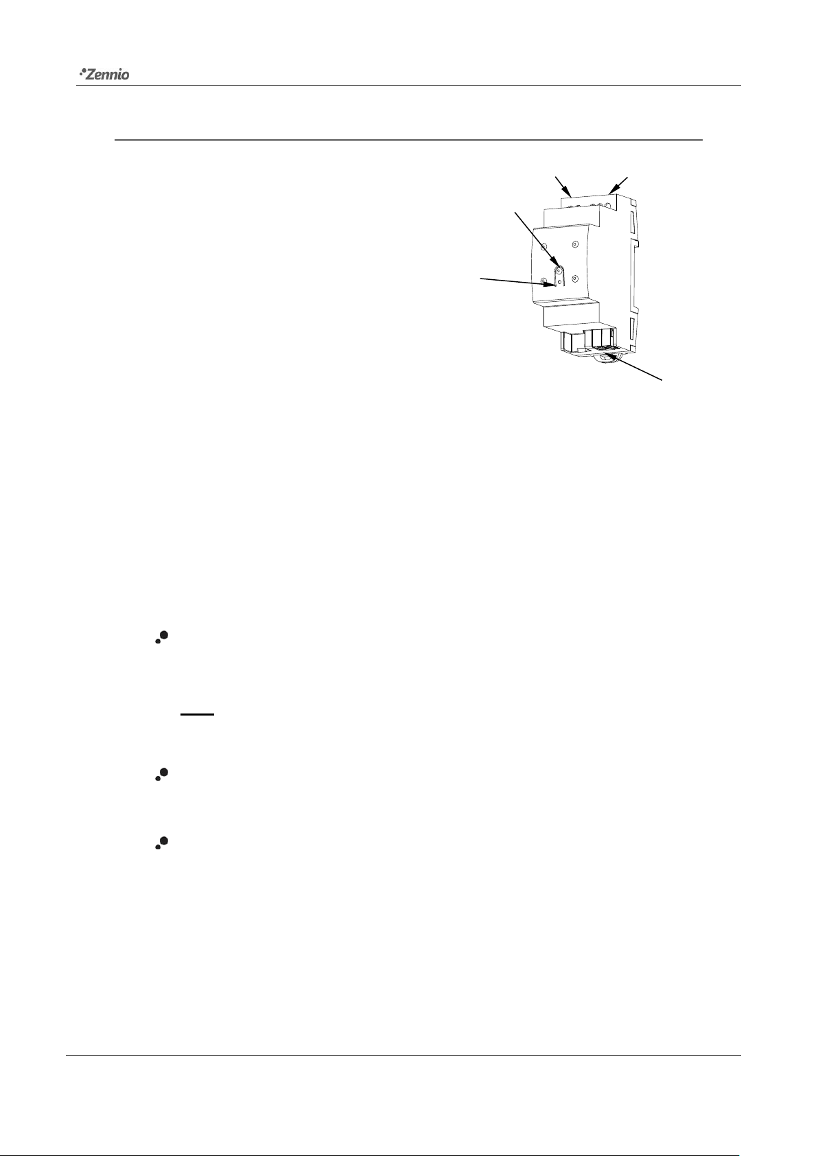
The remaining elements are described next.
Prog./Test button (2): a short press on this button will set the device into the
programming mode, making the associated LED (1) light in red.
Note: if this button is held while plugging the device into the KNX bus, the
device will enter into safe mode. The LED will blink in red every 0.5 seconds
Analogue-Digital Inputs (4): input ports for the stripped cables of external
elements such as switches, motion detectors, temperature probes, etc.
P1/P2 Communication (3): 2-wire communication cable that will connect
KLIC-DI v2 to the A/C unit. The other end of the cable, therefore, is intended to
be connected to the P1/P2 connector in the PCB board of the internal unit.
Figure 1. Element scheme
1. Prog./Test LED
2. Prog./Test button
3. 2-wire communication connection with
A/C unit (P1/P2 port).
4. Inputs Conector.
5. KNX Conector.
4 2 5
3
1
Page 5
KLIC-DI v2
http://www.zennio.com Technical Support: http://support.zennio.com
5
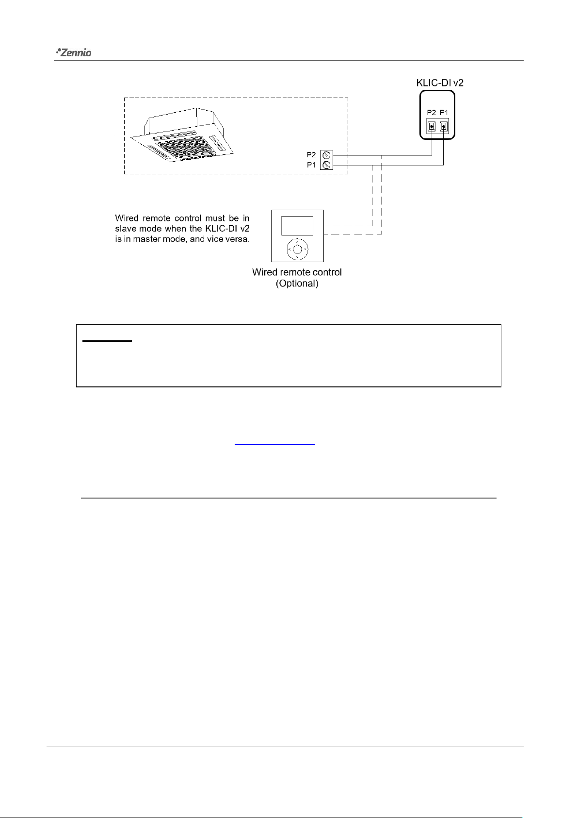
Figure 2. Connecting KLIC-DI v2 to the P1/P2 bus.
Important: if intending to control the A/C unit both through its incorporated wired remote
control and through KLIC-DI v2, it must be taken into account the master-slave
configuration assigned to both of them.
For detailed information about the technical features of KLIC-DI v2, as well as on security
and installation procedures, please refer to the device Datasheet, bundled in the device
packaging and also available at www.zennio.com.
1.3 START-UP AND POWER LOSS
Depending on the configuration, some specific actions will be performed during the
device start-up. The integrator may set up an initial status to be sent to the A/C unit after
the bus power restored, as well as the sending of certain objects to the KNX bus, as
described in later sections.
On the other hand, when a bus power failure takes place, the device will interrupt any
pending actions, and will save its state so it can be recovered once the power supply is
restored.
Page 6

KLIC-DI v2
http://www.zennio.com Technical Support: http://support.zennio.com
6
2 CONFIGURATION
2.1 GENERAL
The general configuration of the device consists in enabling the specific functionalities
that will be required during normal operation:
Heartbeat or periodic “still-alive” notification.
Inputs.
Logic functions.
A/C gateway.
The latter entails all functions specific to KLIC-DI v2, i.e., all the functions related to
interfacing with the A/C unit and to the management of the climate control system.
ETS PARAMETERISATION
After importing the corresponding database in ETS and adding the device into the
topology of the desired project, the configuration process begins by entering the
Parameters tab of the device.
The General screen is shown in the first place, containing the following parameters:
Figure 3. General
Page 7
KLIC-DI v2
http://www.zennio.com Technical Support: http://support.zennio.com
7
A/C Gateway [enabled]
1
: enables the “A/C Gateway” tab in the tree on the left.
For more information, see section 2.2.
Inputs [disabled/enabled]: enables or disables the “Inputs” tab in the tree on
the left, depending on whether the device will or will not be connected any
external accessories. For more information, see section 2.3.
Logic Functions [disabled/enabled]: enables or disables the “Logic Functions”
tab in the tree on the left. For more information, see section 2.4.
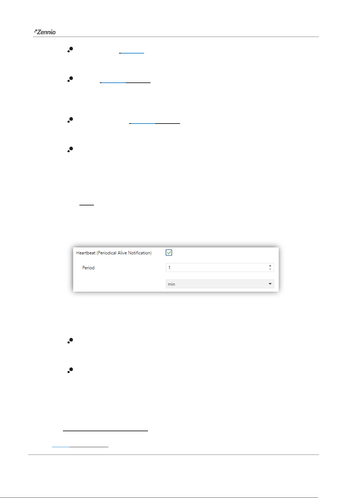
Heartbeat (Periodic Alive Notification): this parameter lets the integrator
incorporate a 1-Bit object to the project (“[Heartbeat] Object to Send ‘1’”) that
will be sent periodically with value “1” to notify that the device is still working
(still alive).
Note: the first sending after download or bus failure takes place with a delay
of up to 255 seconds, to prevent bus overload. The following sendings match
the period set.
Regardless of the above parameters, the following objects are available by default:
“[AC] On/Off” and “[AC] On/Off (Status)”: allow switching on (value “1”) and
off (value “0”) the A/C unit or reading the current status, respectively.
“[AC] Temperature Setpoint” and “[AC] Temperature Setpoint (Status)”:
allow setting the desired temperature setpoint or reading the current value,
respectively. See section 2.2.1 for further options.
1
The default values of each parameter will be highlighted in blue in this document, as follows:
[default/rest of options].
Figure 4. Heartbeat
Page 8

KLIC-DI v2
http://www.zennio.com Technical Support: http://support.zennio.com
8
“[AC] Mode” and “[AC] Mode (Status)”: allow setting the desired operation
mode (either Automatic, Heating, Cooling, Fan or Dry) or reading the current
mode, respectively. See section 2.2.1 for further options.
“[AC] Fan: Percentage Control” and “[AC] Fan: Percentage Control
(Status)”: allow establishing desired fan speed or reading the current fan
speed, respectively. See section 2.2.1.
Several error objects. See section 2.2.4.
Page 9

KLIC-DI v2
http://www.zennio.com Technical Support: http://support.zennio.com
9
2.2 A/C GATEWAY
2.2.1 CONFIGURATION
KLIC-DI v2 allows controlling and monitoring an air-conditioning unit in the same way it
would be through the wired remote control it is provided with.
Through the KNX bus, KLIC-DI v2 can be sent orders to control the following basic
functions of the air conditioning unit:
On/Off switch of the air-conditioning unit.
Operation mode: automatic, heating, cooling, fan and dry.
Temperature setpoint, which can be modified within a 16-32ºC range.
Fan speed: 2 or 3 levels, depending on the model of the A/C unit.
Control of flaps (or vanes) positioning: direct positioning or swing
movement of flaps, depending on the A/C unit.
Moreover, KLIC-DI v2 allows configuring several advanced functions:
Remote control configuration: which allows establishing the type of master-
slave control desired to KLIC-DI v2.
Indoor unit model: allows to select the indoor unit model between VRV and
Sky Air.
Operation mode management (only in VRV units): devices configured as a
master (note that this does not apply to devices configured as a slave) may
also act as a master of mode or as a slave of mode in case multiple indoor
units are connected to the same outdoor unit, which causes restrictions in the
working modes of the indoor units depending on that selected in the outdoor
unit. The configuration of such situation is detailed below.
Reference temperature: which allows supervising reference temperature that
it is taken into account by A/C unit for control temperature. This temperature
can be the internal temperature of A/C unit or an external reference
temperature, provided by a temperature probe.
Page 10

KLIC-DI v2
http://www.zennio.com Technical Support: http://support.zennio.com
10
Setpoint limits: to restrict the range for the temperature setpoint.
Automatic off, which allows an automatic and temporary switch-off of the unit
(after a pre-established delay, if desired) when the communication object
associated to this function is triggered due to a certain event.
Initial configuration, which allows establishing the desired initial parameters
for the state of the A/C unit after programming or restarting the device.
Scenes, which allows defining predefined climate control environments, to be
sent to the machine on the reception of scene orders from the KNX bus.
Operation time, provides in hours and/or seconds the A/C unit operating time.
These functionalities imply changes in the state of the A/C unit, which therefore notifies
KLIC-DI v2 periodically about the current state. When KLIC-D v2 is notified about a
change, it updates the status objects and sends them to the KNX bus. In addition, KLIC-
DI v2 provides an error management function (see section 2.2.4), which allows sending
messages to the KNX bus in case the A/C unit reports any errors.
Page 11
KLIC-DI v2
http://www.zennio.com Technical Support: http://support.zennio.com
11
ETS PARAMETRIZATION
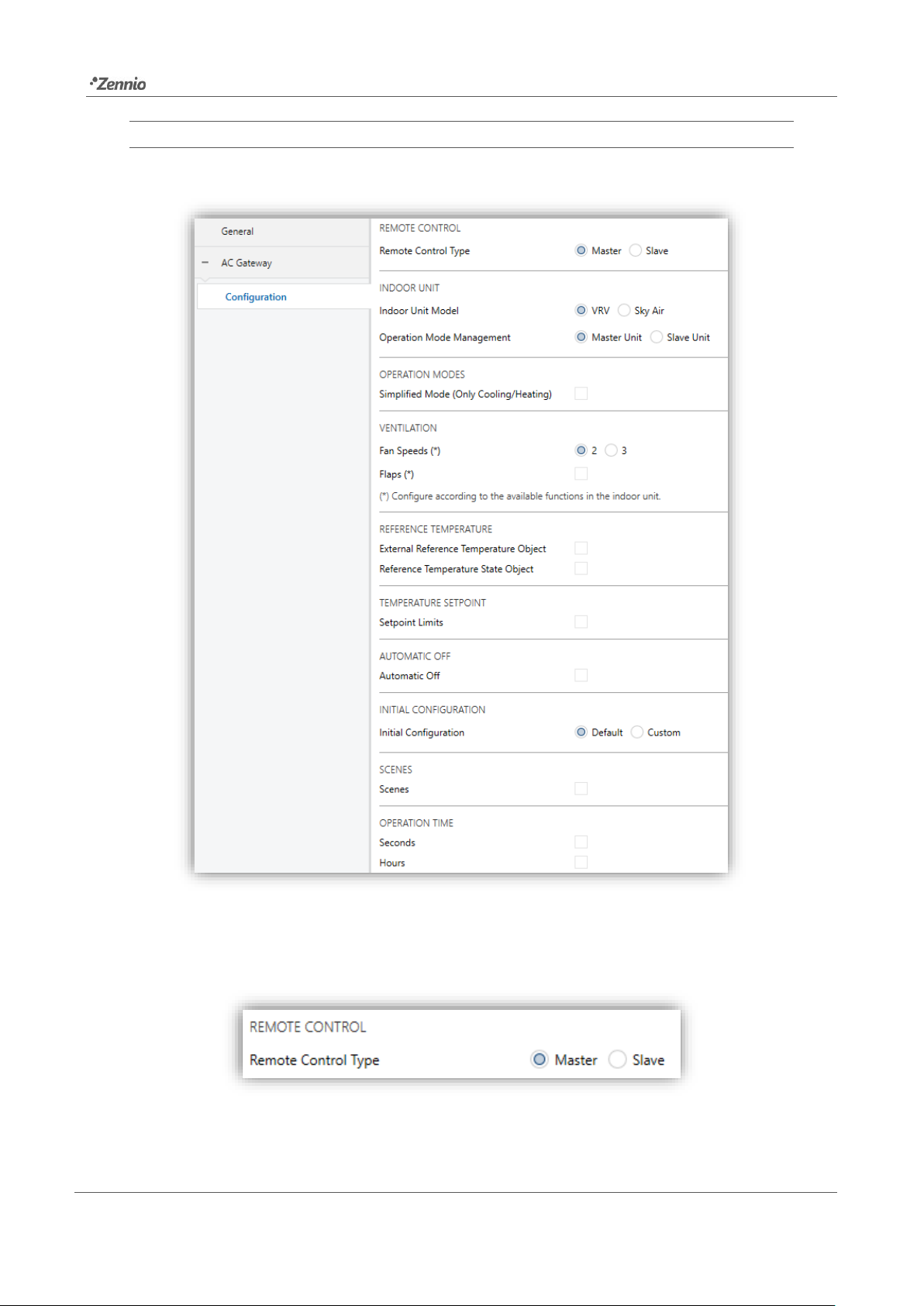
The Configuration window under A/C Gateway provides the following parameters:
REMOTE CONTROL
Figure 5. A/C Gateway. Configuration.
Figure 6. A/C Gateway. Configuration. Remote control.
Page 12
KLIC-DI v2
http://www.zennio.com Technical Support: http://support.zennio.com
12
Remote control type [Master / Slave]: configures the control type of KLIC-DI
v2.
The master control type will correspond to the device which directly
communicates with the machine. It will also be in charge of retransmitting the
instructions to the slave control, if any. This configuration will still permit
controlling the machine from the slave control.
This feature allows connecting to the same installation both the KLIC-DI v2
interface and the wired remote control of the A/C unit.
Important: in case of having KLIC-DI v2 and the wired remote control operating
together, please, make sure that the control type of both devices is not the
same (necessarily one of them must be master and the other slave).
Notes:
➢ Switching the wired control between the slave and master modes requires
interrupting its power supply in order to make the wired control re-initialise
under the new mode.
➢ If the power supply of the wired control fails, it may be necessary to
disconnect and reconnect the bus voltage of the device after the power
supply has been restored in order for the configuration between the wired
control unit and the KLIC-DI v2 to be successful (especially if the KLIC-DI
v2 has been configured as master and the wired control as slave).
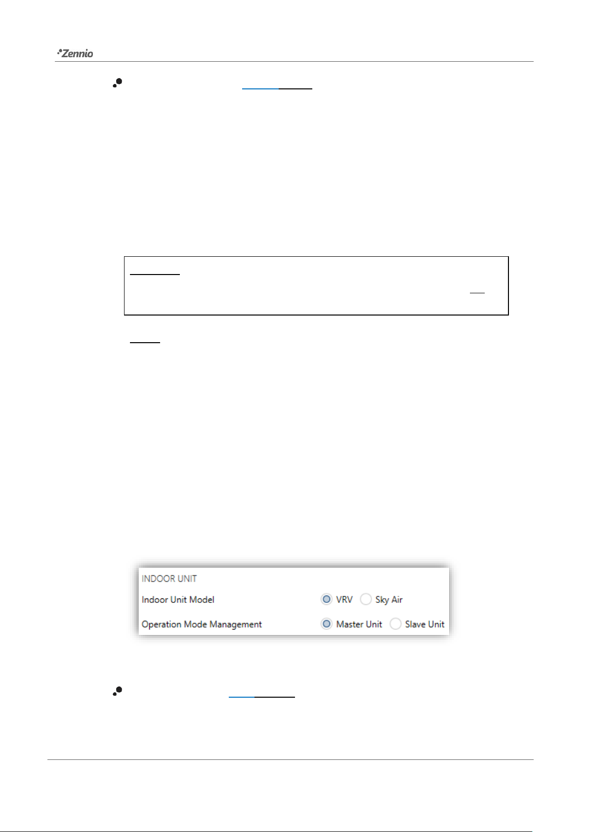
INDOOR UNIT
Indoor unit model [VRV / Sky Air]: KLIC-DI v2 must be configured according
to the indoor unit model which will be controlled.
Figure 7. A/C Gateway. Configuration. Indoor unit.
Page 13

KLIC-DI v2
http://www.zennio.com Technical Support: http://support.zennio.com
13
In case of selecting VRV as the indoor model unit, the following parameter is
enabled:
Operation mode management [Master Unit / Slave Unit].
The concept of the Master Unit derives from the possibility of having multiple
indoor A/C units within the same facility, all of them connected to a single
outdoor unit, which typically means that (unless a BS box has been installed)
only one main mode can be active at a time, and therefore only one internal
unit may work as a master unit, being the only one capable of switching the
active mode. The remaining indoor units (and their respective master or slave
controls) will act as slave units, thus will only have certain modes available,
depending on the currently active main mode.
Table 1 shows the different modes that can be selected from the device
depending on whether it is configured as a master unit or as a slave unit. Note
that in case of acting as a slave unit, the available modes will depend on the
mode currently under selection by the master of mode.
Modes available for selection
Master
Unit
Cool
Heat
Fan
Dry
Slave
Unit
Cool
Fan
Dry
Heat
Fan
Fan
Cool
Fan
Dry
Table 1. Configurable modes from a master of mode and from a slave of mode.
If a KLIC-DI v2, which controls a slave mode unit, changes to a different mode
from allowed modes (according to master unit main mode), the mode of master
unit will be established.
For example, if master unit is operating in Heat mode, the allowed modes in a
slave unit will be Heat and Fan, while disallowed modes will be Cool and Dry.
Thus, if KLIC-DI v2, which controls a slave mode unit, changes to Dry or Cool
mode (disallowed modes), through KNX bus Heat mode will be received.
Conversely, if the slave unit changes to Fan or Heat mode, then there will be
established in this unit and these statuses will be received through KNX bus.
Page 14

KLIC-DI v2
http://www.zennio.com Technical Support: http://support.zennio.com
14
Please, note that simplified mode functionality will not be available with a
configuration of a slave mode unit (“[AC] Simplified Mode”), due to it would
not be useful.
Notes:
➢ If an installation with multiply indoor A/C units connected to a single
outdoor unit has a BS box, all units can change its mode as master unit.
Thus, in case of employing a BS box, all KLIC-DI v2 which control indoor
unit must have configured its “operation mode management” parameter
as master units.
➢ The operation mode management must be configured according to the
type of unit which will be controlled, in order not to cause an abnormal
control or behaviour of the air machine.
OPERATION MODES
KLIC-DI v2 allows controlling the A/C unit operating mode through the following objects,
available by default:
“[AC] Mode”: 1-Byte object which allows selecting the A/C unit operation
mode. There will be only taken in account values that are appropriated with
some of available modes in Daikin units, which are represented in Table 2.
Figure 8. A/C Gateway. Configuration. Operation modes.
Page 15

KLIC-DI v2
http://www.zennio.com Technical Support: http://support.zennio.com
15
“[AA] Mode (status)”: 1-Byte object which allows knowing the A/C unit
operating mode status.
Object Value
A/C unit mode
0
Auto
1
Heating
3
Cooling
9
Fan only
14
Dry
Table 2. A/C unit operating modes.
Additionally, a simplified mode can be configured to select Cooling and Heating mode.
Simplified Mode (Only Cooling/Heating) [disabled/enabled]: in addition to
the “Mode” and “Mode (Status)” 1-Byte objects, available by default, it is
possible to commute and to verify the current operation mode through the
following 1-Bit objects, which get enabled after activating this parameter:
➢ “Simplified Mode”, which allows switching to the Cooling mode by
sending it a “0” and to the Heating mode by sending it a “1”.
➢ “Simplified Mode (Status)”, which will send a value of “0” when the mode
switches to Cooling or to Dry, or a value of “1” when it switches to Heating.
The Fan mode is not reflected in the value of this object. In Auto mode the
value will be actualized depending of the current mode operating: AutoCooling (“0”) or Auto-Heating (“1”).
Notes: In an installation with both KLIC-DI v2 and wired control remote, and
mode changes (Auto-Cool to Auto-Heat or vice versa) are performed from both
controls during automatic mode, that the setpoint/ventilation/flame states are
updated to those of the last time the mode was entered is possible.
Page 16

KLIC-DI v2
http://www.zennio.com Technical Support: http://support.zennio.com
16
VENTILATION
Fan Speeds [2 / 3]: specified the number of the fan levels distinguished by A/C
unit.
KLIC-DI v2 allows the sending of fan speed change orders to the A/C unit to
switch the ventilation speed along the available levels. To that end, KLIC-DI v2
provides a percentage control through the objects “[AC] Fan: percentage
control” y “[AC] Fan: percentage control (Status)”, available by default.
Important: fan speed must be configured according to the available functions
in the A/C unit.
Table 3 and Table 4 reflect the percentage values that refer to several
ventilation levels:
Control Value
Status Value
Level sent to the A/C unit
0-50%
50%
1 (minimum)
51-100%
100%
2 (maximum)
Table 3. Fan Speed for 2 levels of ventilation.
Control Value
Status Value
Level sent to the A/C unit
0-33%
33%
1 (minimum)
34-66%
66%
2
67-100%
100%
3 (maximum)
Table 4. Fan Speed for 3 levels of ventilation.
Figure 9. A/C Gateway. Configuration. Ventilation.
Page 17

KLIC-DI v2
http://www.zennio.com Technical Support: http://support.zennio.com
17
Note: In dry mode, A/C unit sets fan speed in automatic mode. Due to this fact
the fan speed control orders will be ignored during this mode, and will be taken
into account when Dry mode expires.
Flaps [disabled/enabled]. Flaps function allows sending the A/C unit orders to
switch the position of the flaps (or vanes), in case of being available in the unit.
Important: this parameter must be configured according to the available
functions in the A/C unit, in order not to cause an abnormal control or behaviour
of the air machine. Note that, if this parameter is not configured properly, the
communication with a slave remote wired control will not be possible, in case
of having it in the installation.
When flaps are enabled, “[AC] Flaps: Percentage Control” and “[AC] Flaps:
Percentage Control (Status)” 1-byte objects are available, which allow
sending the A/C unit orders to switch the position of the flaps or activating the
swing function and supervising flaps status. Furthermore, it will appear a new
parameter called Movement objects.
Control values
Status value
Position sent to the Unit
0%
0%
Swing
1-20%
20%
Position 1
21-40%
40%
Position 2
41-60%
60%
Position 3
61-80%
80%
Position 4
81-100%
100%
Position 5
Table 5. Flaps Control
➢ Swing objects [disabled/enabled]: enables 1-Bit objects “[AC] Flaps:
Swing” and “[AC] Flaps: Swing (Status)” to activate or not swing
movement and, also, consulting its status.
The parameter Swing object polarity [0 = Swing On; 1 = Swing Off / 0 =
Swing Off; 1 = Swing On] is available to set the polarity of the enabled
objects.
Note: on certain A/C unit models, positions 3-5 may not be available
under the Cool mode, as a measure to prevent that a cold air flow is
Page 18

KLIC-DI v2
http://www.zennio.com Technical Support: http://support.zennio.com
18
outputted directly to particular points of the room where people are
supposed to stand. Analogously, positions 1 and 2 may not be permitted
by the A/C unit under the Heat mode, to prevent hot air accumulation on
the top of the room.
REFERENCE TEMPERATURE
External reference temperature object [disabled/enabled]: enables a 2-Byte
object “[AC] External Reference Temperature” which will receive the
temperature values provided by an external temperature probe and these
values will be employed by the A/C unit to control the temperature (instead of
employing its internal values). If during 3 minutes, no temperature values are
received, values of the internal probe will be recuperated again to execute
temperature control, in the same way as it will be controlled if KLIC-FJ was
configured disabling this option. If a new external temperature value is
received, the control will be again executed by using this external value. The
values allow to be received in this object are include in [0-63.5] ºC (if different
values are received, they will be ignored).
Note: external reference temperature object only will be available if KLIC-DI v2
is configured as master control.
Reference temperature state object [disabled/enabled]: enables a 2-Byte
object “[AC] Reference Temperature (Status)” which informs of the
temperature that the A/C Unit use as reference to do the temperature control
(internal or external).
➢ Sending type: defines the mode in which the reference temperature will be
sent:
Figure 10. A/C Gateway. Configuration. Reference temperature.
Page 19

KLIC-DI v2
http://www.zennio.com Technical Support: http://support.zennio.com
19
• [Variation]: reference temperature will be sent when there is almost a
variation of 0.1ºC, and additionally, 30 seconds have passed from the
previous sending to avoid KNX bus saturation.
• [Periodic]: reference temperature will be sent periodically according to
the configured sending period [[30…3600][s] / [1…15…1440][min] /
[1…24][h]].
• [Periodic + Variation]: consists of the combination of the two previous
options, the sending will be made by variation and periodically.
Note: Daikin indoor units have three different ways to be programmed in
regards with its reference temperature. This configuration must be done by a
Daikin qualified technician or installer using wired remote control.
1) Use of external and internal reference temperature: the indoor unit uses its
own return temperature when there is a big difference between the ambient
temperature and the setpoint temperature. The ambient temperature will be
used from the Master device (remote controller, or KLIC-DI device) when
this difference is small.
2) Use of internal reference temperature: the indoor unit always uses its own
return temperature.
3) Use of external reference temperature: the indoor unit only uses the ambient
temperature from the Master device (Daikin wired remote control or KLIC-DI
v2 device).
This functionality must be configured in the unit according with the KLIC-DI v2
parametrization in order to do an effective temperature control. For example, a
wrong configuration would be one in where indoor unit employs one of the
options that uses external reference temperature and configuring a master
KLIC-DI v2 without external reference temperature to control it.
Page 20

KLIC-DI v2
http://www.zennio.com Technical Support: http://support.zennio.com
20
TEMPERATURE SETPOINT
The following objects to control and supervise setpoint temperature will be available by
default:
“[AC] Temperature Setpoint”: 2-Byte object to select decimal temperature
values that belong to the range [16º-32º].
“[AC] Temperature Setpoint (Status)”: 2-Byte object that provides the
Temperature setpoint status.
Note: A X.Y value will be rounded to X.0 if [Y < 5] or to X.5 if [Y ≥ 5].
Status object will be updated to the last setpoint temperature value received by the A/C
unit after a complete communication cycle and will be sent to KNX bus every time that
its value changes.
Setpoint limits can be configured by parameter:
Setpoint Limits [disabled/enabled]: allows restricting the range of the
temperature setpoint (from below in the Cooling and Auto modes and from
above in the Heating and Auto modes), provided that the limits are still within
the predefined limits of the A/C unit. When KLIC-DI v2 receives an order to
send the A/C unit a setpoint which is greater (or lower) than the configured
limits, it will actually send the limit value.
➢ Minimum (Cooling / Auto Mode) [16...18…32] ºC: sets the upper limit.
➢ Maximum (Heating / Auto Mode) [16...30…32] ºC: sets the lower limit.
Figure 11. A/C Gateway. Configuration. Temperature setpoint.
Page 21

KLIC-DI v2
http://www.zennio.com Technical Support: http://support.zennio.com
21
Once these limits are enabled, several objects to modify them at run time will be
available. The values of this objects will be restricted to an interval which is defined by
the absolute limits established by the A/C unit (10ºC to 32ºC).
“[AC] Temperature Setpoint: Lower Limit”: 2-Byte object that allows
changing the lower limit at run time.
“[AC] Temperature Setpoint: Lower Limit (Status)”: 2-Byte object with the
lower limit current value.
“[AC] Temperature Setpoint: Upper Limit”: 2-Byte object that allows
changing the upper limit at run time.
“[AC] Temperature Setpoint: Upper Limit (Status)”: 2-Byte object with the
upper limit current value.
Notes:
If [Minimum] ≥ [Maximum], limits will not be taken in account in Auto mode due
to the incongruity. In this case, default values will be used.
These parameters only can be set as integer values in ETS. However, at run
time the associated objects allow decimal values.
The A/C unit set a fixed temperature setpoint in Fan and Dry mode, this is the
reason why KLIC-DI v2 will not send the setpoint value to A/C unit, however
the value will be saved in order to be sent when these modes expires.
The setpoint limits set by the A/C unit on each operating mode are indicated in
Table 6, however, these limits can be more restrictive changing the
configuration with the wired remote control:
Mode
Temperature Setpoint
Auto
[16º-32º]
Cooling
[16º-32º]
Heating
[16º-32º]
Fan
Not available
Dry
Not available
Table 6. Interior setpoint limits of A/C unit
Page 22

KLIC-DI v2
http://www.zennio.com Technical Support: http://support.zennio.com
22
AUTOMATIC OFF
Automatic Off [disabled/enabled]: enables the “[AC] Automatic Off” binary
object, which lets performing a temporary switch-off of the A/C unit by sending
it a value of “1” and a later switch-on by sending it a value of “0”. This object
will be typically linked to a window sensor or a similar event trigger. Automatic
off will be also active if the unit is previously in off state, so, the unit will not be
able of being on until this situation finishes.
During the temporary switch-off state, KLIC-DI v2 will still monitor any control
orders being received (setpoint, fan speed, etc.), so they can be applied once
it leaves such state.
➢ Automatic Off Object Polarity [0 = Activate; 1 = Deactivate / 0 =
Deactivate; 1 = Activate]: sets the polarity of the above object.
➢ Automatic Off Delay [1…60…3600] s: sets the time KLIC-DI v2 waits
before switching the A/C machine off. Any switch-off order received during
the delay will abort the time count.
Note: switch-on orders sent to the A/C unit from a wireless control have a
higher priority than the Auto Off mode.
INITIAL CONFIGURATION
Figure 12. A/C Gateway. Configuration. Automatic off.
Figure 13. A/C Gateway. Configuration. Initial configuration.
Page 23

KLIC-DI v2
http://www.zennio.com Technical Support: http://support.zennio.com
23
Initial Configuration: allows setting the desired initial state that KLIC-DI v2
will send the A/C unit after programming or restarting the device:
➢ [Default]: the initial state will be the last one KLIC-DI v2 is aware of.
➢ [Custom]: see section 2.2.2
SCENES
Scenes [disabled/enabled]: allows setting up different scenes (up to 5),
consisting each of them in a set of orders to be sent to the A/C unit upon the
reception of scene trigger values through the KNX bus. See section 2.2.3.
OPERATING TIME
The operating time of the A/A machine in hours and/or seconds can be known.
The available parameters in ETS are:
Seconds [disabled/enabled]: enables the 2-Byte object “[AC] Operating time
(s)”. This object can be read and overwritten during executing time.
Figure 14. A/C Gateway. Configuration. Scenes.
Figure 15. A/C Gateway. Configuration. Operating Time.
Page 24

KLIC-DI v2
http://www.zennio.com Technical Support: http://support.zennio.com
24
Hours [disabled/enabled]: enables the 4-Byte object “[AC] Operating time (h)”.
This object can be read and overwritten during executing time.
➢ Initial Operation Time, two options are available:
• [Keep current value]: keeps the previous value.
• [Set new value]: establishes an initial operating time value [[0…3600][s]
/ [0…65535][h]].
➢ Periodic Sending [[0…3600][s] / [0…65535][min/h]]: operating time
retransmission period. If set to 0 the periodic send is disabled.
When operating time object reaches its maximum value (65535h), it will be sent through
KNX bus (in spite of the fact that the periodical sending has not been configured) and it
will keep this value until the user reset it.
2.2.2 INITIAL CONFIGURATION
The custom initial configuration allows setting the desired status that KLIC-DI v2 will send
the A/C unit after downloading or restarting the device. This status is defined in terms of
on/off, mode, fan speed, flaps position and temperature setpoint.
In addition, it is possible to activate an initial sending of this status to the KNX bus.
ETS PARAMETRISATION
After selecting “Custom” for the Initial Configuration option under the Configuration tab
(see section 2.2.1), a new tab named Initial Configuration is displayed with the
following parameters:
Page 25

KLIC-DI v2
http://www.zennio.com Technical Support: http://support.zennio.com
25
On/Off [Last (before restart) / On / Off].
Mode [Last (before restart) / Automatic / Heating / Cooling / Fan / Dry].
Fan speed [Last (before restart) / 1 / 2 / 3]. The number of speeds (“1 / 2” or
“1 / 2 / 3”) will depend on those selected in the Fan speeds parameter, in the
AA Gateway Configuration tab (see section 2.2.1, ventilation)
Flaps [Not Available]. The following options will only be available if you enable
Flaps in the AA Gateway Configuration tab (see section 2.2.1, ventilation):
[Last (before restart) / Swing / 1 / 2 / 3 / 4 / 5].
Setpoint [disabled/enabled]:
➢ Value:
• [Last (before restart)]: the value of the setpoint temperature will be kept.
Only available if the Setpoint parameter remains disabled.
• [16…25…32] ºC.
Note: this initial setpoint value may be modified by the setpoint limits during
runtime.
Send initial configuration [disabled/enabled]: If enabled, the status objects
will be sent to the KNX bus after applying the parametrized delay [0…3600],
in seconds.
Figure 16. A/C Gateway. Initial configuration.
Page 26

KLIC-DI v2
http://www.zennio.com Technical Support: http://support.zennio.com
26
Notes:
➢ Even if this option is not enabled, the status objects may be sent to the
KNX bus if the initial configuration differs from the current status of the
A/C machine.
➢ The delay parametrized in initial configuration sending is approximate,
due to it starts to be counted when the communication between KLIC-DI
v2 and A/C unit is confirmed.
2.2.3 SCENES
The Scenes function allows defining a set of statuses (in terms of On/Off, mode, fan
speed, etc.) that KLIC-DI v2 will send to the A/C unit whenever it receives the
corresponding scene values from the KNX bus.
ETS PARAMETRISATION
After enabling this function (see section 2.2.1), a new tab named Scenes will be
incorporated to the tab tree. It allows setting up different scenes (up to 5), consisting
each of them in a set of orders to be sent to the A/C unit upon the reception, through the
KNX bus and by means of the Scenes object, of the corresponding scene value
(decreased by 1, according to the KNX standard).
Page 27

KLIC-DI v2
http://www.zennio.com Technical Support: http://support.zennio.com
27
For every enabled scene, the particular parameters that should be configured are:
Scene number [1…64]: sets the scene number that, upon reception through
the object “[AC] Scene” (decreased by one), will trigger the corresponding
orders, as defined next:
➢ On/Off [No change / On / Off]. If "No change" is selected, the machine will
retain the last state before scene reception.
➢ Mode [Last (before restart) / Automatic / Heating / Cooling / Fan / Dry].
➢ Fan speed [No change / 1 / 2 / 3]. The number of speeds (“1 / 2” or “1 / 2 /
3”) will depend on those selected in the Fan speeds parameter, in the AA
Gateway Configuration tab (see section 2.2.1, ventilation)
➢ Flaps [Not Available]. The following options will only be available if you
enable Flaps in the AA Gateway Configuration tab (see section 2.2.1,
ventilation): [No change / Swing / 1 / 2 / 3 / 4 / 5].
➢ Setpoint [disabled/enabled]:
Figure 17. A/C Gateway. Scenes.
Page 28

KLIC-DI v2
http://www.zennio.com Technical Support: http://support.zennio.com
28
• Value:
o [No change]: the value of the setpoint temperature will be kept. Only
available if the Setpoint parameter remains disabled.
o [16…25…32] ºC.
Note: this setpoint value may be modified by the setpoint limits during
runtime.
2.2.4 ERROR HANDLING
KLIC-DI v2 is capable of managing two error types:
Communication or internal errors: errors in the communication process
between KLIC-DI v2 and the A/C unit:
➢ Communication error: KLIC-DI v2 is not able to establish communication
with the A/C machine.
There is a LED notification, by which the LED on the device will light green
when communication error is active.
➢ Wrong acknowledgement: KLIC-DI v2 received an unexpected response
after sending a request to the A/C unit.
There is a LED notification, by which the LED on the device will blink every
0.5 seconds in green and stay off for other 3 seconds when wrong
acknowledgement error is active.
Errors in the A/C unit: errors reported by the A/C unit itself. KLIC-DI v2 can
notify the KNX bus about the reported error code, although referring to the
specific documentation of the A/C machine is advisable in order to obtain further
information.
ETS PARAMETRISATION
The error handling function does not entail any parameter configuration. The following
objects are available by default:
Page 29

KLIC-DI v2
http://www.zennio.com Technical Support: http://support.zennio.com
29
Internal error objects:
➢ “[AC] Internal Error: Communication”: 1-Bit object to indicate that KLIC-
DI v2 is unable to access to the internal communication port.
➢ “[AC] Internal Error: Wrong acknowledgement”: 1-Bit object to
indicate that an unexpected response or a response with transmission
errors has been received.
In case any of the above errors is detected, the corresponding object will be
sent periodically (with a value of “1”) to the KNX bus. Once the error is over, it
the object will be sent (once) with a value of “0”.
In case of being in an internal error situation, control orders will be ignored by
KLIC-DI v2 and the status will be the previous to the error activation.
Errors in the A/C machine:
➢ “[AC] A/C unit Error: Active Error”: 1-Bit object which indicate that there
is an error in the A/C unit.
➢ “[AC] A/C unit Error: Error Code”: 14-Byte object that supplies the error
code.
In case the A/C unit reports an error, the former object will be sent with value of “1”, while
the latter will report the corresponding error code. Once the error is over, both binary and
14-byte objects will send a value of “0”. Please, refer to the user manual of the A/C unit
for details about the error codes.
Page 30

KLIC-DI v2
http://www.zennio.com Technical Support: http://support.zennio.com
30
2.3 INPUTS
KLIC-DI v2 incorporates two analogue/digital inputs, each configurable as a:
Binary Input, for the connection of a pushbutton or a switch/sensor.
Temperature Probe, for the connection of a temperature sensor from Zennio.
Motion Detector, for the connection of a motion detector from Zennio.
2.3.1 BINARY INPUT
Please refer to the “Binary Inputs” user manual, available in the KLIC-DI v2 product
section, at the Zennio website (www.zennio.com).
2.3.2 TEMPERATURE PROBE
Please refer to the “Temperature Probe” user manual, available in the KLIC-DI v2
product section, at the Zennio website (www.zennio.com).
2.3.3 MOTION DETECTOR
Please refer to the “Motion Detector” user manual, available in the KLIC-DI v2 product
section, at the Zennio website (www.zennio.com).
Page 31

KLIC-DI v2
http://www.zennio.com Technical Support: http://support.zennio.com
31
2.4 LOGIC FUNCTIONS
This module makes it possible to perform numeric and binary operations with incoming
values received from the KNX bus, and to send the results through other communication
objects specifically enabled for this purpose.
KLIC-DI v2 can implement up to 10 different and independent functions, each of them
entirely customisable and consisting in up to 4 consecutive operations each.
The execution of each function can depend on a configurable condition, which will be
evaluated every time the function is triggered through specific, parameterisable
communication objects. The result after executing the operations of the function can also
be evaluated according to certain conditions and afterwards sent (or not) to the KNX
bus, which can be done every time the function is executed, periodically or only when
the result differs from the last one.
Please refer to the “Logic Functions” user manual (available in the KLIC-DI v2 product
section at the Zennio homepage, www.zennio.com) for detailed information about the
functionality and the configuration of the related parameters.
Page 32

KLIC-DI v2
http://www.zennio.com Technical Support: http://support.zennio.com
32
ANNEX I. COMMUNICATION OBJECTS
“Functional range” shows the values that, with independence of any other values permitted by the bus according to the object size, may be of any use or have a
particular meaning because of the specifications or restrictions from both the KNX standard or the application program itself.
Number
Size
I/O
Flags
Data type (DPT)
Functional Range
Name
Function
1
1 Byte
I/O
C T R W U
DPT_SceneControl
0-63; 128-191
[AC] Scene
0 - 63 (Execute 1 - 64); 128 - 129 (Save
1 - 64)
2
1 Bit
I
C - - W -
DPT_Switch
0/1
[AC] On/Off
0 = Off; 1 = On
3
1 Bit
O
C T R - -
DPT_Switch
0/1
[AC] On/Off (Status)
0 = Off; 1 = On
4
2 Bytes
I
C - - W -
DPT_Value_Temp
16 - 32
[AC] Temperature Setpoint
[16 ... 32] ºC
5
2 Bytes
O
C T R - -
DPT_Value_Temp
16 – 32
[AC] Temperature Setpoint (Status)
[16 ... 32] ºC
6
2 Bytes
I
C - - W -
DPT_Value_Temp
16 – 32
[AC] Temperature Setpoint: Lower Limit
[16 ... 32] ºC
7
2 Bytes
O
C T R - -
DPT_Value_Temp
16 – 32
[AC] Temperature Setpoint: Lower Limit
(Status)
[16 ... 32] ºC
8
2 Bytes
I
C - - W -
DPT_Value_Temp
16 – 32
[AC] Temperature Setpoint: Upper Limit
[16 ... 32] ºC
9
2 Bytes
O
C T R - -
DPT_Value_Temp
16 – 32
[AC] Temperature Setpoint: Upper Limit
(Status)
[16 ... 32] ºC
10
1 Byte
I
C - - W -
DPT_HVACContrMode
0 = Auto
1 = Heat
3 = Cool
9 = Fan
14 = Dry
[AC] Mode
0 = Automatic; 1 = Heating; 3 = Cooling;
9 = Fan; 14 = Dry
11
1 Byte
O
C T R - -
DPT_HVACContrMode
0 = Auto
1 = Heat
3 = Cool
9 = Fan
14 = Dry
[AC] Mode (Status)
0 = Automatic; 1 = Heating; 3 = Cooling;
9 = Fan; 14 = Dry
12
1 Bit
I
C - - W -
DPT_Heat_Cool
0/1
[AC] Simplified Mode
0 = Cooling; 1 = Heating
13
1 Bit
O
C T R - -
DPT_Heat_Cool
0/1
[AC] Simplified Mode (Status)
0 = Cooling; 1 = Heating
14
1 Byte
I
C - - W -
DPT_Scaling
0 - 100
[AC] Fan: Percentage Control
[0...50.20] % = S1; [50.59...100] % =
S2
1 Byte
I
C - - W -
DPT_Scaling
0 - 100
[AC] Fan: Percentage Control
[0...33.33] % = S1; [33.73...66.67] % =
S2; [67.06...100] % = S3
Page 33

KLIC-DI v2
http://www.zennio.com Technical Support: http://support.zennio.com
33
15
1 Byte
O
C T R - -
DPT_Scaling
0 - 100
[AC] Fan: Percentage Control (Status)
50.20 % = S1; 100 % = S2
1 Byte
O
C T R - -
DPT_Scaling
0 - 100
[AC] Fan: Percentage Control (Status)
33.33 % = S1; 66.67 % = S2; 100 % =
S3
16
1 Byte
I
C - - W -
DPT_Scaling
0 - 100
[AC] Flaps: Percentage Control
0 % = Swing; [0.39...20] % = P1;
[20.39...40] % = P2; [40.39...60] % =
P3; [60.39...80] % = P4; [80.39...100] %
= P5
17
1 Byte
O
C T R - -
DPT_Scaling
0 - 100
[AC] Flaps: Percentage Control (Status)
0 % = Swing; 20 % = P1; 40 % = P2; 60
% = P3; 80 % = P4; 100 % = P5
18
1 Bit
I
C - - W -
DPT_Switch
0/1
[AC] Flaps: Swing
0 = Swing Off; 1 = Swing On
1 Bit
I
C - - W -
DPT_Switch
0/1
[AC] Flaps: Swing
0 = Swing On; 1 = Swing Off
19
1 Bit
O
C T R - -
DPT_Switch
0/1
[AC] Flaps: Swing (Status)
0 = Swing Off; 1 = Swing On
1 Bit
O
C T R - -
DPT_Switch
0/1
[AC] Flaps: Swing (Status)
0 = Swing On; 1 = Swing Off
20
2 Bytes
I
C - - W -
DPT_Value_Temp
0 - 99
[AC] External Reference Temperature
[0 ... 99] ºC
21
2 Bytes
O
C T R - -
DPT_Value_Temp
-273.00 – 670433.28
[AC] Reference Temperature (Status)
Effective Control Temperature (ºC)
22
1 Bit
I
C - - W -
DPT_Switch
0/1
[AC] Automatic Off
0 = Deactivate; 1 = Activate
1 Bit
I
C - - W -
DPT_Switch
0/1
[AC] Automatic Off
0 = Activate; 1 = Deactivate
23
1 Bit
O
C T R - -
DPT_Switch
0/1
[AC] Automatic Off (Status)
0 = Deactivated; 1 = Activated
1 Bit
O
C T R - -
DPT_Switch
0/1
[AC] Automatic Off (Status)
0 = Activated; 1 = Deactivated
24
2 Bytes
I
C - - W -
DPT_TimePeriodSec
0 - 3600
[AC] Automatic Off: Delay
[0...3600] s (0 = Disabled)
25
4 Bytes
I/O
C T R W -
DPT_LongDeltaTimeSec
-2147483648 - 2147483647
[AC] Operating Time (s)
Operation time in seconds
26
2 Bytes
I/O
C T R W -
DPT_TimePeriodHrs
0 - 65535
[AC] Operating Time (h)
Operation time in hours
27
1 Bit
O
C T R - -
DPT_Alarm
0/1
[AC] Internal Error: Communication
Unable to Set AC Communication
28
1 Bit
O
C T R - -
DPT_Alarm
0/1
[AC] Internal Error: Wrong
Acknowledgement
Acknowledgement Received with Errors
29
1 Bit
O
C T R - -
DPT_Alarm
0/1
[AC] AC Unit Error: Active Error
AC Unit Error
30
14 Bytes
O
C T R - -
DPT_String_ASCII
14 ASCII Character
[AC] AC Unit Error: Error Code
See AC Unit Manual
31, 35
2 Bytes
O
C T R - -
DPT_Value_Temp
-273.00 – 670433.28
[Ix] Current Temperature
Temperature Sensor Value
32, 36
1 Bit
O
C T R - -
DPT_Alarm
0/1
[Ix] Overcooling
0 = No Alarm; 1 = Alarm
33, 37
1 Bit
O
C T R - -
DPT_Alarm
0/1
[Ix] Overheating
0 = No Alarm; 1 = Alarm
34, 38
1 Bit
O
C T R - -
DPT_Alarm
0/1
[Ix] Probe Error
0 = No Alarm; 1 = Alarm
39, 45
1 Bit
I
C - - W -
DPT_Enable
0/1
[Ix] Input Lock
0 = Unlock; 1 = Lock
40, 46
1 Bit
C T - - -
DPT_Switch
0/1
[Ix] [Short Press] 0
Sending of 0
1 Bit
C T - - -
DPT_Switch
0/1
[Ix] [Short Press] 1
Sending of 1
1 Bit
I
C T - W -
DPT_Switch
0/1
[Ix] [Short Press] 0/1 Switching
Switching 0/1
1 Bit
C T - - -
DPT_UpDown
0/1
[Ix] [Short Press] Move Up Shutter
Sending of 0 (Up)
1 Bit
C T - - -
DPT_UpDown
0/1
[Ix] [Short Press] Move Down Shutter
Sending of 1 (Down)
Page 34

KLIC-DI v2
http://www.zennio.com Technical Support: http://support.zennio.com
34
1 Bit
C T - - -
DPT_UpDown
0/1
[Ix] [Short Press] Move Up/Down
Shutter
Switching 0/1 (Up/Down)
1 Bit
C T - - -
DPT_Step
0/1
[Ix] [Short Press] Stop/Step Up Shutter
Sending of 0 (Stop/Step Up)
1 Bit
C T - - -
DPT_Step
0/1
[Ix] [Short Press] Stop/Step Down
Shutter
Sending of 1 (Stop/Step Down)
1 Bit
C T - - -
DPT_Step
0/1
[Ix] [Short Press] Stop/Step Shutter
(Switched)
Switching of 0/1 (Stop/Step Up/Down)
4 Bit
C T - - -
DPT_Control_Dimming
0x0 (Stop)
0x1 (Dec. by 100%)
...
0x7 (Dec. by 1%)
0x8 (Stop)
0xD (Inc. by 100%)
...
0xF (Inc. by 1%)
[Ix] [Short Press] Brighter
Increase Brightness
4 Bit
C T - - -
DPT_Control_Dimming
0x0 (Stop)
0x1 (Dec. by 100%)
...
0x7 (Dec. by 1%)
0x8 (Stop)
0xD (Inc. by 100%)
...
0xF (Inc. by 1%)
[Ix] [Short Press] Darker
Decrease Brightness
4 Bit
C T - - -
DPT_Control_Dimming
0x0 (Stop)
0x1 (Dec. by 100%)
...
0x7 (Dec. by 1%)
0x8 (Stop)
0xD (Inc. by 100%)
...
0xF (Inc. by 1%)
[Ix] [Short Press] Brighter/Darker
Switch Bright/Dark
1 Bit
C T - - -
DPT_Switch
0/1
[Ix] [Short Press] Light On
Sending of 1 (On)
1 Bit
C T - - -
DPT_Switch
0/1
[Ix] [Short Press] Light Off
Sending of 0 (Off)
1 Bit
I
C T - W -
DPT_Switch
0/1
[Ix] [Short Press] Light On/Off
Switching 0/1
1 Byte
C T - - -
DPT_SceneControl
0-63; 128-191
[Ix] [Short Press] Run Scene
Sending of 0 - 63
1 Byte
C T - - -
DPT_SceneControl
0-63; 128-191
[Ix] [Short Press] Save Scene
Sending of 128 - 191
1 Bit
I/O
C T R W -
DPT_Switch
0/1
[Ix] [Switch/Sensor] Edge
Sending of 0 or 1
1 Byte
C T - - -
DPT_Value_1_Ucount
0 - 255
[Ix] [Short Press] Constant Value
(Integer)
0 - 255
1 Byte
C T - - -
DPT_Scaling
0 - 100
[Ix] [Short Press] Constant Value
(Percentage)
0% - 100%
Page 35

KLIC-DI v2
http://www.zennio.com Technical Support: http://support.zennio.com
35
2 Bytes
C T - - -
DPT_Value_2_Ucount
0 - 65535
[Ix] [Short Press] Constant Value
(Integer)
0 - 65535
2 Bytes
C T - - -
9.xxx
-671088.64 – 670433.28
[Ix] [Short Press] Constant Value
(Float)
Float Value
41, 47
1 Byte
I
C - - W -
DPT_Scaling
0 – 100
[Ix] [Short Press] Shutter Status
(Input)
0% = Top; 100% = Bottom
1 Byte
I
C - - W -
DPT_Scaling
0 - 100
[Ix] [Short Press] Dimming Status
(Input)
0% - 100%
42, 48
1 Bit
C T - - -
DPT_Switch
0/1
[Ix] [Long Press] 0
Sending of 0
1 Bit
C T - - -
DPT_Switch
0/1
[Ix] [Long Press] 1
Sending of 1
1 Bit
I
C T - W -
DPT_Switch
0/1
[Ix] [Long Press] 0/1 Switching
Switching 0/1
1 Bit
C T - - -
DPT_UpDown
0/1
[Ix] [Long Press] Move Up Shutter
Sending of 0 (Up)
1 Bit
C T - - -
DPT_UpDown
0/1
[Ix] [Long Press] Move Down Shutter
Sending of 1 (Down)
1 Bit
C T - - -
DPT_UpDown
0/1
[Ix] [Long Press] Move Up/Down
Shutter
Switching 0/1 (Up/Down)
1 Bit
C T - - -
DPT_Step
0/1
[Ix] [Long Press] Stop/Step Up Shutter
Sending of 0 (Stop/Step Up)
1 Bit
C T - - -
DPT_Step
0/1
[Ix] [Long Press] Stop/Step Down
Shutter
Sending of 1 (Stop/Step Down)
1 Bit
C T - - -
DPT_Step
0/1
[Ix] [Long Press] Stop/Step Shutter
(Switched)
Switching of 0/1 (Stop/Step Up/Down)
4 Bit
C T - - -
DPT_Control_Dimming
0x0 (Stop)
0x1 (Dec. by 100%)
...
0x7 (Dec. by 1%)
0x8 (Stop)
0xD (Inc. by 100%)
...
0xF (Inc. by 1%)
[Ix] [Long Press] Brighter
Long Pr. -> Brighter; Release -> Stop
4 Bit
C T - - -
DPT_Control_Dimming
0x0 (Stop)
0x1 (Dec. by 100%)
...
0x7 (Dec. by 1%)
0x8 (Stop)
0xD (Inc. by 100%)
...
0xF (Inc. by 1%)
[Ix] [Long Press] Darker
Long Pr. -> Darker; Release -> Stop
4 Bit
C T - - -
DPT_Control_Dimming
0x0 (Stop)
0x1 (Dec. by 100%)
...
0x7 (Dec. by 1%)
0x8 (Stop)
0xD (Inc. by 100%)
[Ix] [Long Press] Brighter/Darker
Long Pr. -> Brighter/Darker; Release ->
Stop
Page 36

KLIC-DI v2
http://www.zennio.com Technical Support: http://support.zennio.com
36
...
0xF (Inc. by 1%)
1 Bit
C T - - -
DPT_Switch
0/1
[Ix] [Long Press] Light On
Sending of 1 (On)
1 Bit
C T - - -
DPT_Switch
0/1
[Ix] [Long Press] Light Off
Sending of 0 (Off)
1 Bit
I
C T - W -
DPT_Switch
0/1
[Ix] [Long Press] Light On/Off
Switching 0/1
1 Byte
C T - - -
DPT_SceneControl
0-63; 128-191
[Ix] [Long Press] Run Scene
Sending of 0 - 63
1 Byte
C T - - -
DPT_SceneControl
0-63; 128-191
[Ix] [Long Press] Save Scene
Sending of 128 - 191
1 Bit
O
C T R - -
DPT_Alarm
0/1
[Ix] [Switch/Sensor] Alarm: Breakdown
or Sabotage
1 = Alarm; 0 = No Alarm
2 Bytes
C T - - -
9.xxx
-671088.64 – 670433.28
[Ix] [Long Press] Constant Value (Float)
Float Value
2 Bytes
C T - - -
DPT_Value_2_Ucount
0 - 65535
[Ix] [Long Press] Constant Value
(Integer)
0 - 65535
1 Byte
C T - - -
DPT_Scaling
0 - 100
[Ix] [Long Press] Constant Value
(Percentage)
0% - 100%
1 Byte
C T - - -
DPT_Value_1_Ucount
0 - 255
[Ix] [Long Press] Constant Value
(Integer)
0 - 255
43, 49
1 Bit
C T - - -
DPT_Trigger
0/1
[Ix] [Long Press/Release] Stop Shutter
Release -> Stop Shutter
44, 50
1 Byte
I
C - - W -
DPT_Scaling
0 - 100
[Ix] [Long Press] Dimming Status
(Input)
0% - 100%
1 Byte
I
C - - W -
DPT_Scaling
0 - 100
[Ix] [Long Press] Shutter Status (Input)
0% = Top; 100% = Bottom
51
1 Byte
I
C - - W -
DPT_SceneNumber
0 - 63
[Motion Detector] Scene Input
Scene Value
52
1 Byte
C T - - -
DPT_SceneControl
0-63; 128-191
[Motion Detector] Scene Output
Scene Value
53, 82
1 Byte
O
C T R - -
DPT_Scaling
0 - 100
[Ix] Luminosity
0-100%
54, 83
1 Bit
O
C T R - -
DPT_Alarm
0/1
[Ix] Open Circuit Error
0 = No Error; 1 = Open Circuit Error
55, 84
1 Bit
O
C T R - -
DPT_Alarm
0/1
[Ix] Short Circuit Error
0 = No Error; 1 = Short Circuit Error
56, 85
1 Byte
O
C T R - -
DPT_Scaling
0 - 100
[Ix] Presence State (Scaling)
0-100%
57, 86
1 Byte
O
C T R - -
DPT_HVACMode
1=Comfort
2=Standby
3=Economy
4=Building Protection
[Ix] Presence State (HVAC)
Auto, Comfort, Standby, Economy,
Building Protection
58, 87
1 Bit
O
C T R - -
DPT_Switch
0/1
[Ix] Presence State (Binary)
Binary Value
1 Bit
O
C T R - -
DPT_Ack
0/1
[Ix] Presence: Slave Output
1 = Motion Detected
59, 88
1 Bit
I
C - - W -
DPT_Window_Door
0/1
[Ix] Presence Trigger
Binary Value to Trigger the Presence
Detection
60, 89
1 Bit
I
C - - W -
DPT_Ack
0/1
[Ix] Presence: Slave Input
0 = Nothing; 1 = Detection from slave
device
61, 90
2 Bytes
I
C - - W -
DPT_TimePeriodSec
0 - 65535
[Ix] Presence: Waiting Time
0-65535 s.
62, 91
2 Bytes
I
C - - W -
DPT_TimePeriodSec
1 - 65535
[Ix] Presence: Listening Time
1-65535 s.
63, 92
1 Bit
I
C - - W -
DPT_Enable
0/1
[Ix] Presence: Enable
According to parameters
Page 37

KLIC-DI v2
http://www.zennio.com Technical Support: http://support.zennio.com
37
64, 93
1 Bit
I
C - - W -
DPT_DayNight
0/1
[Ix] Presence: Day/Night
According to parameters
65, 94
1 Bit
O
C T R - -
DPT_Occupancy
0/1
[Ix] Presence: Occupancy State
0 = Not Occupied; 1 = Occupied
66, 95
1 Bit
I
C - - W -
DPT_Ack
0/1
[Ix] External Motion Detection
0 = Nothing; 1 = Motion detected by an
external sensor
67, 72, 77, 96,
101, 106
1 Byte
O
C T R - -
DPT_Scaling
0 - 100
[Ix] [Cx] Detection State (Scaling)
0-100%
68, 73, 78, 97,
102, 107
1 Byte
O
C T R - -
DPT_HVACMode
1=Comfort
2=Standby
3=Economy
4=Building Protection
[Ix] [Cx] Detection State (HVAC)
Auto, Comfort, Standby, Economy,
Building Protection
69, 74, 79, 98,
103, 108
1 Bit
O
C T R - -
DPT_Switch
0/1
[Ix] [Cx] Detection State (Binary)
Binary Value
70, 75, 80, 99,
104, 109
1 Bit
I
C - - W -
DPT_Enable
0/1
[Ix] [Cx] Enable Channel
According to parameters
71, 76, 81, 100,
105, 110
1 Bit
I
C - - W -
DPT_Switch
0/1
[Ix] [Cx] Force State
0 = No Detection; 1 = Detection
[111-142]
1 Bit
I
C - - W -
DPT_Bool
0/1
[LF] (1-Bit) Data Entry x
Binary Data Entry (0/1)
[143-158]
1 Byte
I
C - - W -
DPT_Value_1_Ucount
0 - 255
[LF] (1-Byte) Data Entry x
1-Byte Data Entry (0-255)
[159-174]
2 Bytes
I
C - - W -
DPT_Value_2_Ucount
DPT_Value_2_Count
DPT_Value_Temp
0 – 65535
-32768 -32767
-273.00 – 670433.28
[LF] (2-Byte) Data Entry x
2-Byte Data Entry
[175-182]
4 Bytes
I
C - - W -
DPT_Value_4_Count
-2147483648 - 2147483647
[LF] (4-Byte) Data Entry x
4-Byte Data Entry
[183-192]
1 Bit
O
C T R - -
DPT_Bool
0/1
[LF] Function x - Result
(1-Bit) Boolean
1 Byte
O
C T R - -
DPT_Value_1_Ucount
0 - 255
[LF] Function x - Result
(1-Byte) Unsigned
2 Bytes
O
C T R - -
DPT_Value_2_Ucount
0 - 65535
[LF] Function x - Result
(2-Byte) Unsigned
4 Bytes
O
C T R - -
DPT_Value_4_Count
-2147483648 - 2147483647
[LF] Function x - Result
(4-Byte) Signed
1 Byte
O
C T R - -
DPT_Scaling
0 - 100
[LF] Function x - Result
(1-Byte) Percentage
2 Bytes
O
C T R - -
DPT_Value_2_Count
-32768 - 32767
[LF] Function x - Result
(2-Byte) Signed
2 Bytes
O
C T R - -
DPT_Value_Temp
-273.00 – 670433.28
[LF] Function x - Result
(2-Byte) Float
193
1 Bit
C T - - -
DPT_Trigger
0/1
[Heartbeat] Object to Send '1'
Sending of '1' Periodically
Page 38

Join and send us your inquiries
about Zennio devices:
http://support.zennio.com
Zennio Avance y Tecnología S.L.
C/ Río Jarama, 132. Nave P-8.11
45007 Toledo (Spain).
Tel. +34 925 232 002.
www.zennio.com
info@zennio.com
 Loading...