

Daikin FXKQ-M, FXFQ-P, FXCQ-A, FXSQ-P, FXFQ-A Service Manual
...
Service
Manual
VRV4 indoor units
ESIE15-11A
BRYQ-A
BYCQ-D
CAV/CYV
VKM
FXKQ-M
FXFQ-P
FXCQ-A
FXSQ-P
FXDQ-M
FXUQ-A
FXFQ-A
FXMQ-P
FXHQ-A
FXDQ-A
FXZQ-A
FXAQ-P
FXLQ
FXNQ
FXSQ-A
FXTQ-A

VRV4 indoor units
ESIE15-11A |
The present publication is drawn up by way of information only and does not constitute an offer binding upon Daikin Europe N.V.
Daikin Europe N.V. has compiled the content of this publication to the best of its knowledge. No express or implied warranty is
given for the completeness, accuracy, reliability or fitness for particular purpose of its content and the products and services
presented therein. Specifications are subject to change without prior notice. Daikin Europe N.V. explicitly rejects any liability for
any direct or indirect damage, in the broadest sense, arising from or related to the use and/or interpretation of this publication. All
content is copyrighted by Daikin Europe N.V.
Page 2 23/09/16

VRV4 indoor units
ESIE15-11A |
Table of contents
Part 1. Introduction ....................................................................................................................5
1. Version log ....................................................................................................................................................5
2. System description ........................................................................................................................................6
2.1. General system layout of a VRV heat recovery system .................................................................................... 6
3. General operation of VRV heat recovery system ..........................................................................................9
4. How to use this book ...................................................................................................................................10
4.1. Interactive information flow .............................................................................................................................. 10
Part 2. Troubleshooting ...........................................................................................................11
1. How to retrieve error code and data? .........................................................................................................11
1.1. Wired remote controller BRC1D ...................................................................................................................... 11
1.1.1. Access to error code ................................................................................................................................... 11
1.1.2. Access to inspection menu ......................................................................................................................... 11
1.1.3. Access to Service menu ............................................................................................................................. 13
1.2. Wired remote controller BRC1/2/3E ................................................................................................................ 14
1.2.1. Access to error code ................................................................................................................................... 14
1.2.2. Access to service menu .............................................................................................................................. 15
1.3. Wireless controller BRC4/7 .............................................................................................................................17
1.3.1. Access to error code ................................................................................................................................... 17
2. Error code based troubleshooting ...............................................................................................................18
Part 3. Field settings ................................................................................................................21
1. Wireless remote controller BRC4C and BRC7C/E .....................................................................................21
1.1. Access field settings ........................................................................................................................................ 21
2. Wired remote controller BRC2/3E52 ...........................................................................................................22
2.1. Access field settings ........................................................................................................................................ 22
2.2. Field settings, specific for wired remote controller BRC2/3E52 ...................................................................... 25
3. Wired remote controller BRC1D51/52 ........................................................................................................27
3.1. Access field settings ........................................................................................................................................ 27
3.2. Field settings, specific for BRC1D51/52 .......................................................................................................... 28
4. Wired remote controller BRC1E51 ..............................................................................................................30
4.1. Access field settings ........................................................................................................................................ 30
4.2. Field settings, specific for BRC1E51 ...............................................................................................................32
5. Wired remote controller BRC1E52 ..............................................................................................................35
5.1. Access field settings ........................................................................................................................................ 35
5.2. Field settings, specific for BRC1E52 ...............................................................................................................37
6. General indoor units ....................................................................................................................................41
7. Presence sensor BRYQ140A7 (for 3x3 cassette) / BRYQ60A7 (for 2x2 cassette) ....................................46
8. Selfcleaning panel BYCQ140D7G ..............................................................................................................47
9. Aircurtain CAV/CYV ....................................................................................................................................48
10. VKM ..........................................................................................................................................................48
11. FXSQ-A / FXNQ-A / FXDQ-A / FXMQ-P/MB / FXTQ-A ............................................................................51
12. Factory settings .........................................................................................................................................53
12.1. How to perform factory reset of settings through remocon ...........................................................................53
12.2. Field settings as per type indoor unit ............................................................................................................. 55
23/09/16 Page 3

VRV4 indoor units
ESIE15-11A |
Page 4 23/09/16
VRV4 indoor units
ESIE15-11A | Part 1. Introduction 1. Version log
Part 1. Introduction
1. Version log
Version code Description Date
ESIE15-11 Release 10/12/15
ESIE15-11A Add error codes A0, A1, A7, A9-01, A9-02, UE 23/09/16
23/09/16 Page 5
VRV4 indoor units
Multi BS
Single BS
Single BS
Refnet KHRQ23M……
LP gas + HP gas + liquid
Gas (LP or HP)
+ liquid
LP gas + HP gas + liquid
Gas (LP or HP)
+ liquid
Gas HP + liquid
Refnet
BHFQ23P…
Refnet
KHRQ22M……
VRV DX
indoor
VRV4 heat recovery
outdoor units
VRV low
temperature
hydro unit
VRV high
temperature
hydro unit
VRV DX
indoor
ESIE15-11A | Part 1. Introduction 2. System description
2. System description
This system description explains the concept of the VRV4 H/R. All settings in this book however, are applicable to indoor units that
can be connected to VRV4 HP, mini-VRV4, VRV i-series, VRV4 high ambient and VRV4 water-cooled.
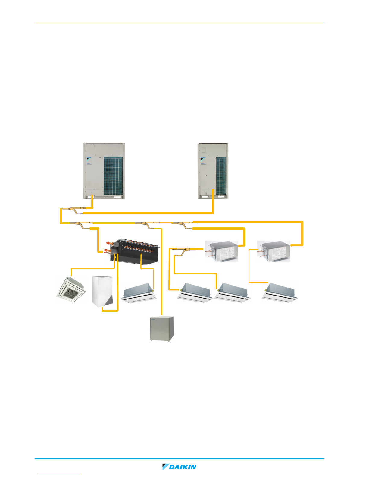
2.1. General system layout of a VRV heat recovery system
The VRV heat recovery system consists of 3 different types of units:
• outdoor unit(s)
• BS unit (Branch Selector unit)
• indoor units.
• One to maximum three modules of VRV4 heat recovery outdoor unit can be connected using the optional refnet “BHFQ23P…”.
• Field piping must be thermally insulated copper piping, connected to a combination of “Single circuit BS” unit(s), or/and “Multi
circuit BS” unit(s).
• The “Single circuit BS” unit offers 1 change-over circuit. A “Multi circuit BS” unit offers 4, 6, 8, 10, 12 or 16 outlets.
• To split the refrigerant circuit between outdoor unit(s) and the different BS units, Daikin optional accessory refnets (reference
“KHRQ23M…”) are used.
• Behind the BS unit, one or more indoor units can be connected. To split the refrigerant circuit to the different indoor units to
the same BS unit, Daikin optional accessory refnets (reference “KHRQ22M…”) are used.
• The HT (high temperature) hydrobox is connected without BS unit: only use the HP (high pressure) gas line and the liquid line.
Page 6 23/09/16
VRV4 indoor units
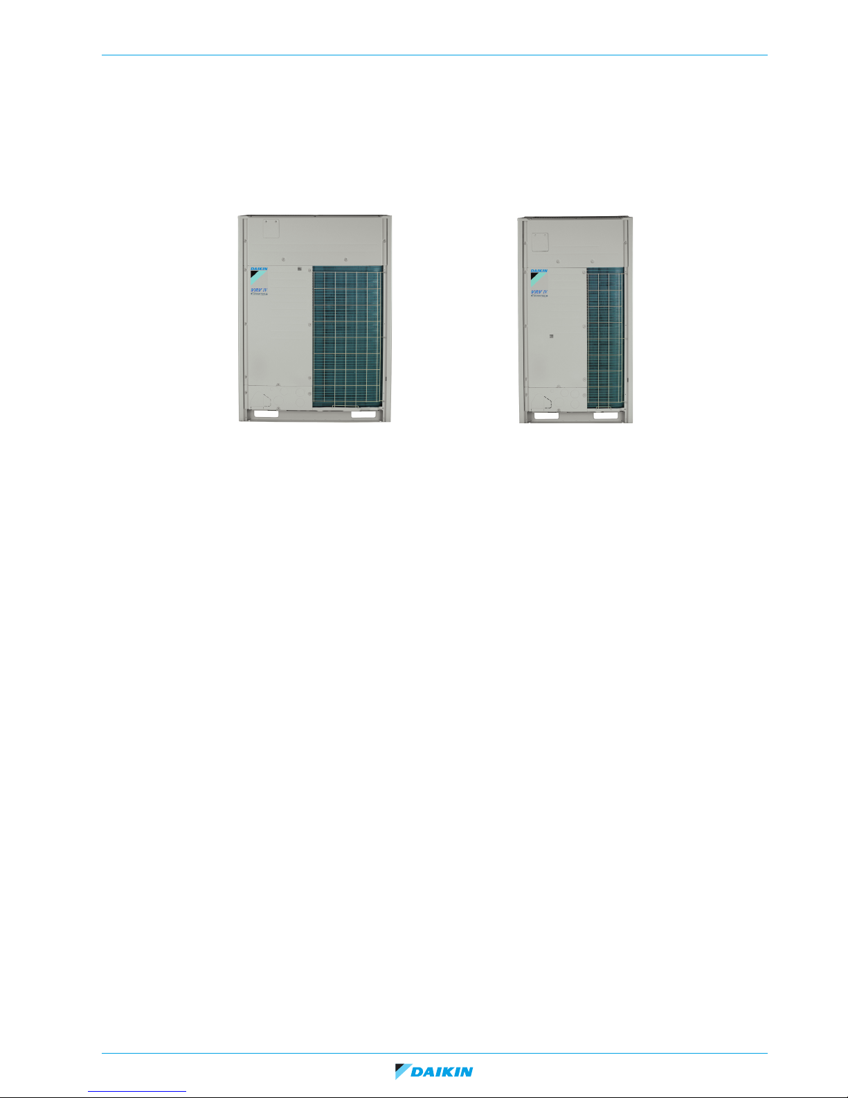
“Medium” casing“Large” casing
ESIE15-11A | Part 1. Introduction 2. System description
1. Outdoor units exist in different capacities. Two types of casings are used:
- “Medium” casing: REMQ5T7Y1B, REYQ8~12T7Y1B
- “Large” casing: REYQ14~20T7Y1B
- The unit REYQ8~20T7Y1B can be used as “single” unit or combined into a “multi” outdoor combination of maximum three
units (refer to databook).
- The unit REMQ5T7Y1B can only be used in multi 2* REMQ5T7Y1B or REMQ5T7Y1B + REYQ8T7Y1B.
23/09/16 Page 7

VRV4 indoor units
ESIE15-11A | Part 1. Introduction 2. System description
2. BS “branch selector” units exists in:
- “Single circuit” BS units: 3 capacities available depending on total capacity indoor units:
• BS1Q10A: indoor index below 100 (100 not included).
• BS1Q16A: indoor index from 100 and below 160.
• BS1Q25A: indoor index from 160 till 250 (250 included).
BS1Q10, 16, 25A
- “Multi circuit” BS units:
• The maximum number of circuits depend on the model:
- BS4Q14A: maximum 4 circuits.
- BS6Q14A: maximum 6 circuits.
- BS8Q14A: maximum 8 circuits.
- BS10Q14A: maximum 10 circuits.
- BS12Q14A: maximum 12 circuits.
- BS16Q14A: maximum 16 circuits.
• Each circuit can have:
- Maximum five indoor units.
- Maximum index 140.
3. Indoor units:
- The current available type VRV DX units can be used. Minimum 50% of outdoor index must be connected through BS
unit(s).
- The LT (low temperature) hydro unit can be added (BS unit required).
- The HT hydro unit can be added (without BS unit).
Page 8 23/09/16
BS10Q14A
VRV4 indoor units
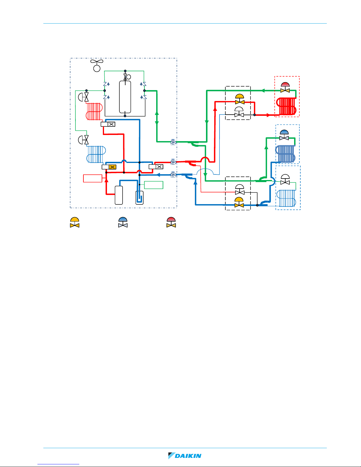
“SC”
4 way valve
Receiver
“SH”
off
“Tc”
Pc D Tc
HP sensor
LP sensor
Closed
Compressor
on off
EVL
EVH
Expansion
valve
Suction
accumulator
BS unit -
cooling
BS unit -
heating
VRV indoor heating
VRV indoor cooling
Fully open Superheat Sub-cool
Fan
motor
VRV outdoor
“SH” & “Te”
Pe D Te
ESIE15-11A | Part 1. Introduction 3. General operation of VRV heat recovery system
3. General operation of VRV heat recovery system
• When indoor unit is selecting heating mode, discharge gas is supplied by the outdoor unit(s) into the dual pressure line through
EVH (high pressure expansion valve) fully opened in the BS unit to the indoor unit.
• When indoor unit is selecting cooling mode, suction gas returns from indoor unit gas line through EVL (low pressure expansion
valve) fully opened in the BS unit to the outdoor unit.
• Indoor unit in cooling controls the indoor expansion valve on suction superheat (SH) by comparing gas and coil sensor on
indoor unit.
• Indoor unit in heating controls the indoor expansion valve on liquid sub-cool (SC) by comparing Tc (outdoor condensing
temperature) derived from reading of high pressure sensor, and indoor coil temperature.
• When indoor unit requires change over between cooling and heating, the switching between suction and discharge line is
performed only in the BS unit that received the request of indoor unit to change over. Change over sequence is explained in
“General built up VRV4 BS unit”.
• Outdoor can switch outdoor heat exchanger separately condenser/evaporator in function of unbalance between cooling and
heating demand indoor side.
23/09/16 Page 9
VRV4 indoor units
O
S
tts
Wh
at
d
ESIE15-11A | Part 1. Introduction 4. How to use this book
4. How to use this book
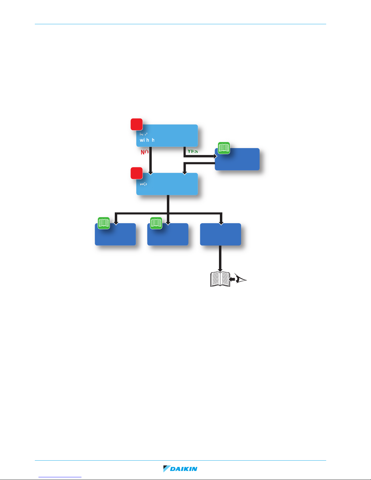
4.1. Interactive information flow
This Daikin product Service Manual is intended for professional use only. The actions described hereafter, are only to be performed
by qualified and certified persons.
By following the diagram below, the reader can find the relevant information related to his/her task. The digital (pdf) version of this
book allows direct page access through all active links. When Adobe Acrobat Reader is used, the <Alt> + <Back Arrow> keys can
be used to return to the previously viewed page.
?
Is this your 1st encounter
with this particular unit?
PART 2
Troubleshooting
NO
?
What do you need to do?
PART 3
Field settings
YES
General
operation
Installation
Refer to:
Installation Manual
or
Installer Reference Guide
Page 10 23/09/16
VRV4 indoor units
ESIE15-11A | Part 2. Troubleshooting 1. How to retrieve error code and data?
Part 2. Troubleshooting
This part contains the following chapters:
1. How to retrieve error code and data? .........................................11
2. Error code based troubleshooting...............................................18
1. How to retrieve error code and data?
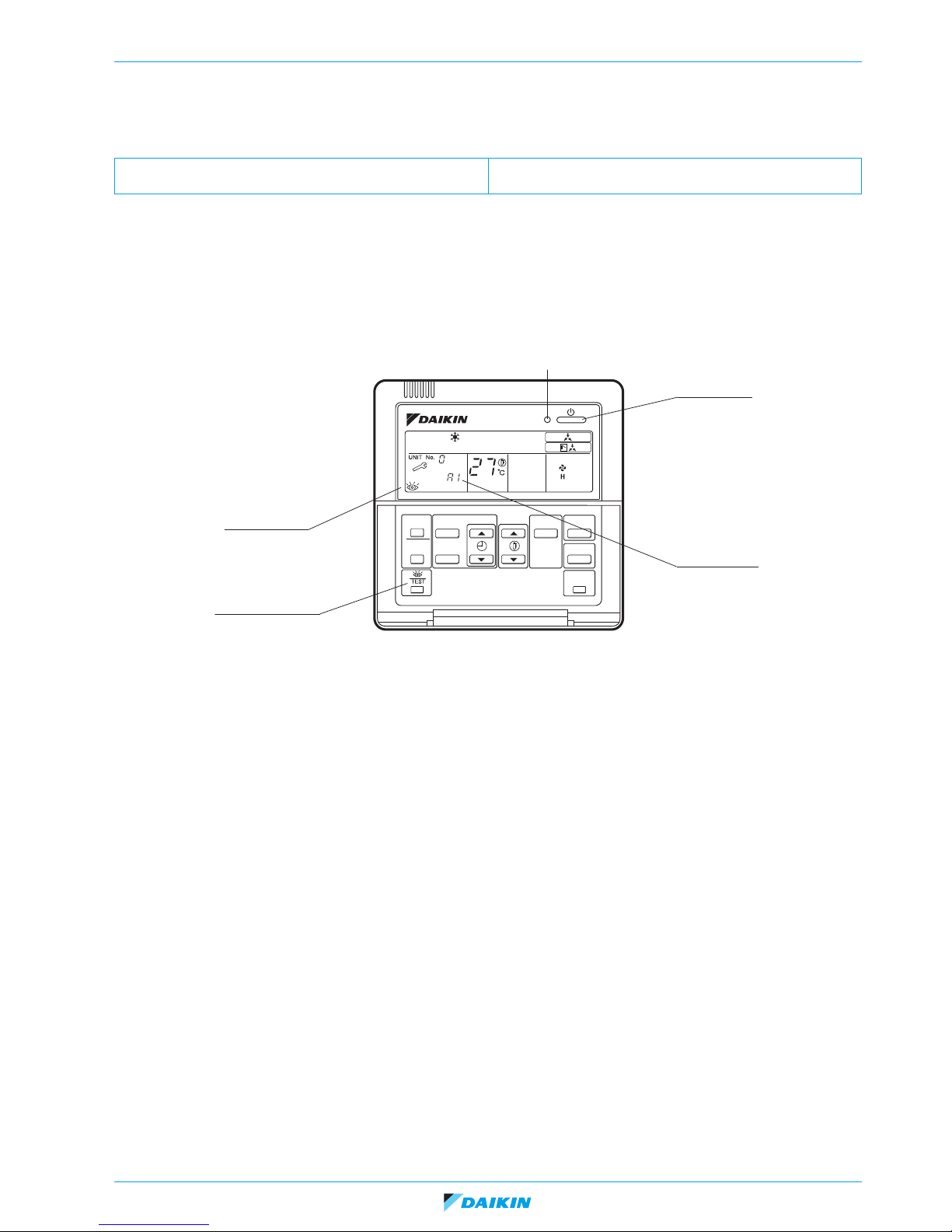
1.1. Wired remote controller BRC1D
Operation LED
ON/OFF button
Inspection display
Malfunction code
Inspection/Test button
1.1.1. Access to error code
If operation stops due to malfunction, the remote controller's operation LED blinks, and malfunction code is displayed. (Even if stop
operation is carried out, malfunction contents are displayed when the inspection mode is entered.)
The malfunction code enables you to tell what kind of malfunction caused operation to stop.
1.1.2. Access to inspection menu
In the inspection menu, you can check the error codes, indoor unit model code, outdoor unit model code and start test operation
if required.
To enter Inspection menu, push the TEST button once. The symbol of an eye (inspection) will light up on the remote controller
display.
23/09/16 Page 11
VRV4 indoor units
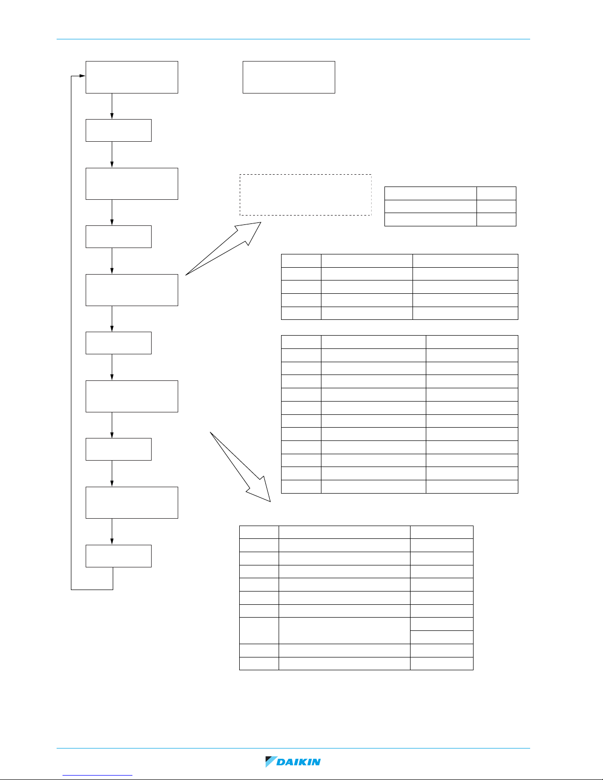
Normal display (No display)
Inspection/test
operation
Press the button.
Error code blinks when an error occurs.
Unit
Error code
Inspection
0
L 0
Unit
Error code
Inspection
0
L 0
Inspection mode
Inspection/test
operation
Press the button.
0 7 1
F C J
Indoor unit model code display
Press the button.
Inspection/test
operation
? – – –
A A 1
Outdoor unit model code display
Press the button.
Inspection/test
operation
Test operation
Test operation mode
Press the button.
Inspection/test
operation
Capacity code
Indoor unit system code
Indoor unit type code
Progression code
0 7 1...
F...
C...
J...
Example of capacity code display
Example model Display
FXCQ25 028
FXFQ63 071
Indoor unit system code
Indoor unit type code
Display Product classification System classification
1 VRV system (VAV indoor unit)
2 VRV system
Outdoor air processing unit
F VRV system Standard indoor unit
H VRV system
New ceiling suspended cassette
Display Type Model
A Wall mounted FXAQ
C 2-way blow FXCQ
E Corner FXKQ
F Round flow FXFQ
H Ceiling suspended FXHQ
J Concealed ceiling FXSQ
P Floor standing FXLQ
U Concealed ceiling FXMQ
L
Concealed floor standing type
FXNQ
6 600×600 4-way blow FXZQ
3 Slim concealed ceiling FXDQ
Outdoor model code
Display Type Model
A A 1
VRV System Inverter K Series RSXYP
A A 3
R-407C VRV PLUS Series RXYP
A 9 2
VRV Heat Recovery Series RSEYP
A A 5
High COP type R-407C L Series RSXYP-L
A A A
VRV II RXYQ-M
A A C
VRV II M/C RXYQ-MA
A A E
VRV III Heat Pump Series RXYQ-P
Cooling Only Series RXQ-P
A 9 E
VRV III Heat Recovery Series REYQ-P
A 5 E
VRV III-C Heat Pump Series RTSYQ-PA
ESIE15-11A | Part 2. Troubleshooting 1. How to retrieve error code and data?
Page 12 23/09/16
VRV4 indoor units
Temperature ºC
41
Sensor data display
Unit No. Sensor type
1 1
2 7
Address
41
Address display
Unit No. Address type
1 8
1
(VE008)
Unit 1
43
(VE009)
ESIE15-11A | Part 2. Troubleshooting 1. How to retrieve error code and data?
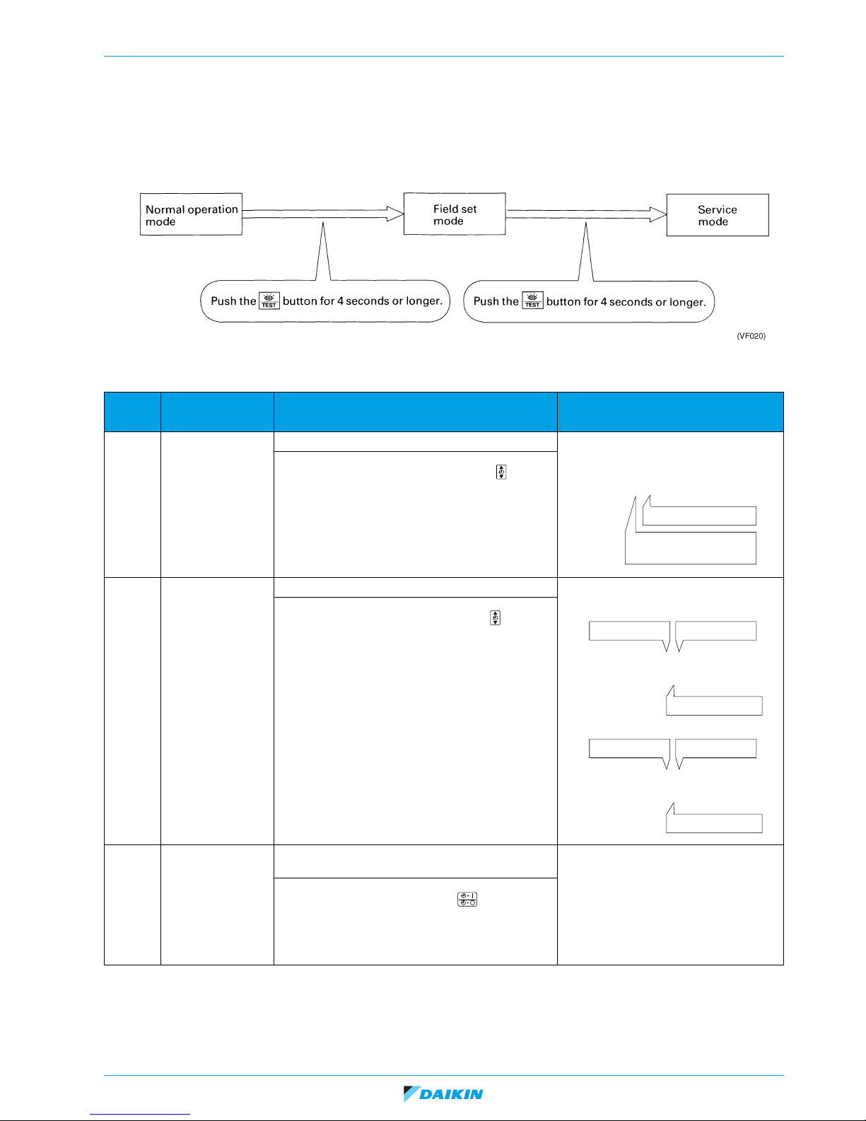
1.1.3. Access to Service menu
When there is no error displayed but unit is behaving strangely, you can also check some more operational data in the Service
mode.
How to access the Service menu:
In the Service menu you can find below information:
Mode
No
40
41
Function Contents and operation method Remote controller display example
Malfunction history
display
Display of sensor
and address data
Display malfunction history.
The history No. can be changed with the but-
ton.
Display various types of data.
Select the data to be displayed with the button.
Sensor data
0: Thermostat sensor in remote controller.
1: Suction (or level if DDC-controller connected. 00 =
level 1 etc.)
2: Liquid pipe
3: Gas pipe
Address data
8: Cool/heat group address
9: Demand / low noise address
Unit 1
Malfunction code
2-U4
Malfunction code
History No: 1 - 9
(VE007)
1: Latest
40
43
Switching between Mode number 40-41-43 is done by pushing the up and down button. To return to normal operation: push the
test button one time.
23/09/16 Page 13
Forced fan ON Manually turn the fan ON by each unit. (When you
want to search for the unit No.)
By selecting the unit No. with the button, you
can turn the fan of each AHU on (forced ON) individually.
VRV4 indoor units
Screen
Operation
lamp
ESIE15-11A | Part 2. Troubleshooting 1. How to retrieve error code and data?
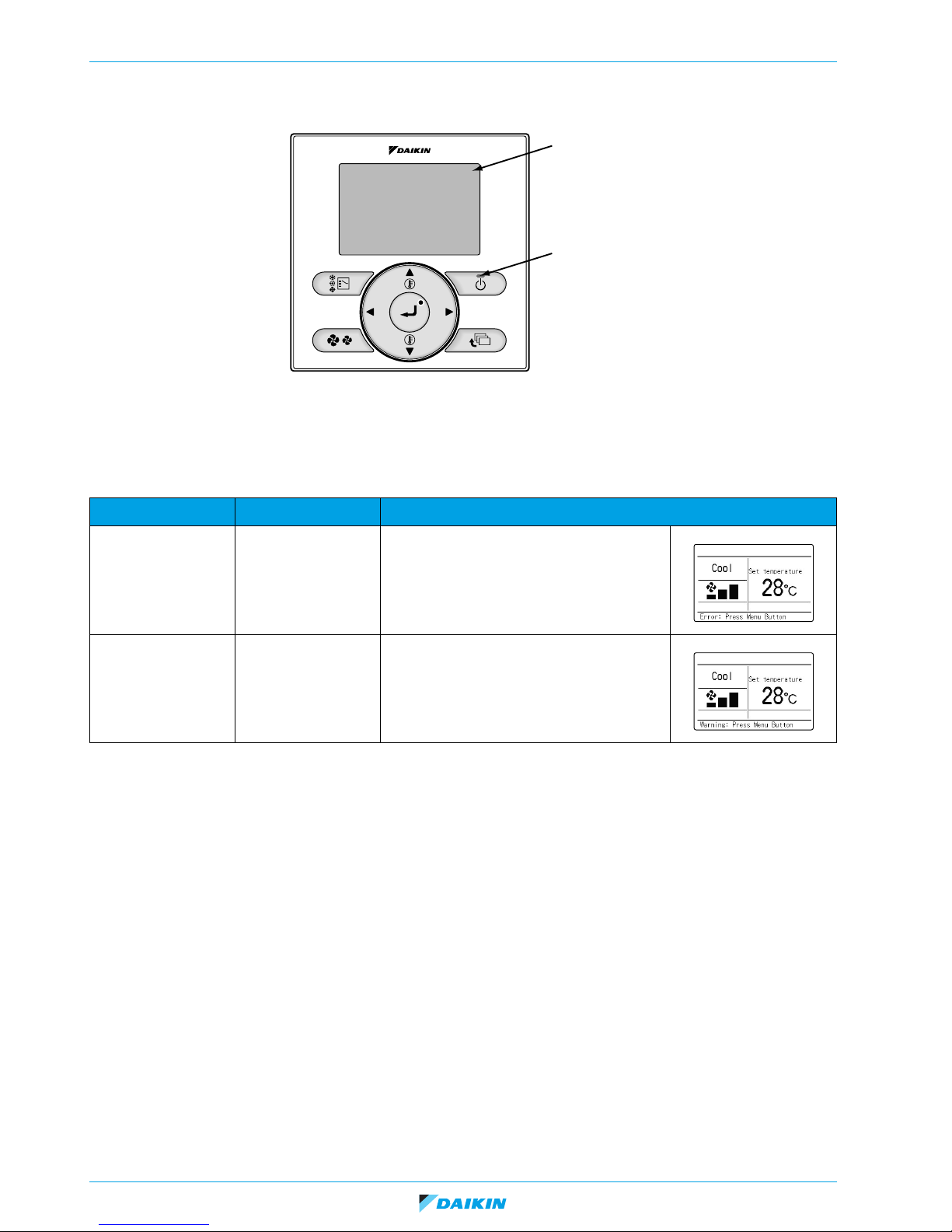
1.2. Wired remote controller BRC1/2/3E
1.2.1. Access to error code
If operation stops due to malfunction, the remote controller's operation LED blinks, and malfunction code is displayed.
The malfunction code enables you to tell what kind of malfunction caused operation to stop.
Operation Status Display
Abnormal shutdown The system stops
operating.
Warning The system continues
its operation.
The operation lamp (green) starts to blink. The
message "Error: Press Menu button" will appear
and blink at the bottom of the screen.
The operation lamp (green) remains on. The message "Warning: Press Menu button" will appear
and blink at the bottom of the screen.
Page 14 23/09/16
VRV4 indoor units
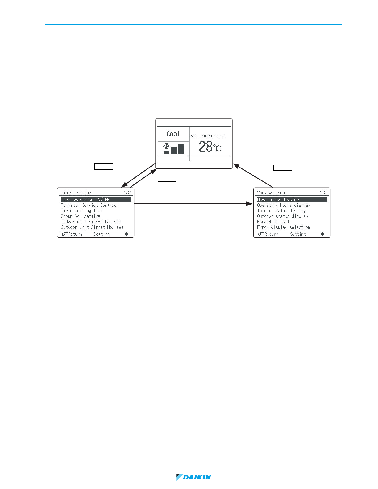
<Basic Screen>
• Operation mode changeover
• Fan speed control
• Menu display
• Confirmation of each setting
• On
• Off
• Cancel
• Operation lamp
Field Setting screen Service Menu screen
<Field Setting Menu>
• Test operation ON/OFF
• Register Service Contract
• Field setting list
• Group No. setting
• Indoor unit AIRNET No. set
• Outdoor unit AIRNET No. set
• Error record
• Indoor status display
• Outdoor status display
• Fan forced operation ON
• Main/Sub changeover
• Filter element sign OFF
<Service Menu>
• Model name display
• Operating hours display
• Indoor status display
• Outdoor status display
• Forced defrost
• Error display selection
• Unit No. transfer
• Sensor/address data display
Basic screen
Press Cancel button
for 4 seconds or more.
Press Cancel
button once.
Press Cancel
button once.
Press Cancel button
for 4 seconds or more.
ESIE15-11A | Part 2. Troubleshooting 1. How to retrieve error code and data?
1.2.2. Access to service menu
When there is no error displayed but unit is behaving strangely, you can also check some more operational data in the Service
menu.
How to access the Service menu:
23/09/16 Page 15

VRV4 indoor units
ESIE15-11A | Part 2. Troubleshooting 1. How to retrieve error code and data?
Below items can be consulted in the Service Menu:
Service Menu Item 2 Remarks
1. Model Name Display
2. Operating Hours Display
3. Indoor Status Display 1/2
3. Indoor Status Display 2/2
1. Unit No.
2. Indoor unit
3. Outdoor unit
1. Unit No.
2. Indoor unit operating time
3. Indoor unit fan operation
4. Indoor unit energized time
5. Outdoor operating time
6. Outdoor unit fan 1 operation
7. Outdoor unit fan 2 operation
8. Outdoor comp. 1 operation
9. Outdoor comp. 2 operation
1. Unit No.
2. FAN
3. FLAP
4. Speed
5. EV
6. MP
7. 52H
8. Hu
9. Anti-freezing
1. Unit No.
Select the Unit No. you want to check.
Select the Unit No. you want to check.
All of these are displayed in hours.
Select the Unit No. you want to check.
Tap, speed (rpm)
Swing, fixed
Fan speed (rpm)
Degree that electronic expansion valve is open (pls)
Drain pump ON/OFF
Electric heater ON/OFF
Humidifier ON/OFF
Anti-freezing control ON/OFF
Select the Unit No. you want to check.
VRV
4. Outdoor Status Display
2. Th1
3. Th2
4. Th3
5. Th4
6. Th5
7. Th6
1. Unit No.
2. FAN Tap 1
3. COMP
4. EV1
5. SV1
Suction air thermistor
Heat exchanger liquid pipe thermistor
Heat exchanger gas pipe thermistor
Discharge air thermistor
—
—
Select the Unit No. you want to check.
Fan tap
Compressor power supply frequency (Hz)
Degree that electronic expansion valve is open (pls)
Solenoid valve ON/OFF
VRV
5. Error Display Selection
6. Unit No. Transfer
6. Th1
7. Th2
8. Th3
1. Warning display ON
2. Warning display OFF
3. Error display ON
4. Error display OFF
1. Current Unit No.
2. Transfer Unit No.
—
—
—
Displays a warning on the screen if an error occurs.
No warning is displayed.
Displays the error on the screen.
Displays neither errors nor warnings.
A unit No. can be transferred to another.
7. Sensor Address Display Unit No.: 0 - 15 Select the Unit No. you want to check.
Code
00:
01:
02:
03:
04:
05:
06:
07:
08:
09:
Remote controller thermistor (°C)
Suction air thermistor (°C)
Heat exchanger liquid pipe thermistor (°C)
Heat exchanger gas thermistor (°C)
Indoor unit address No.
Outdoor unit address No.
BS unit address No.
Zone control address No.
Cooling/heating batch address No.
Demand/low-noise address No.
Data The corresponding data will be displayed, based on the
Unit No. and Code selected.
Page 16 23/09/16
VRV4 indoor units
0ACEHFJLPU987654
"UP" button "DOWN" button
0123456789AHCJEF
"UP" button "DOWN" button
ESIE15-11A | Part 2. Troubleshooting 1. How to retrieve error code and data?
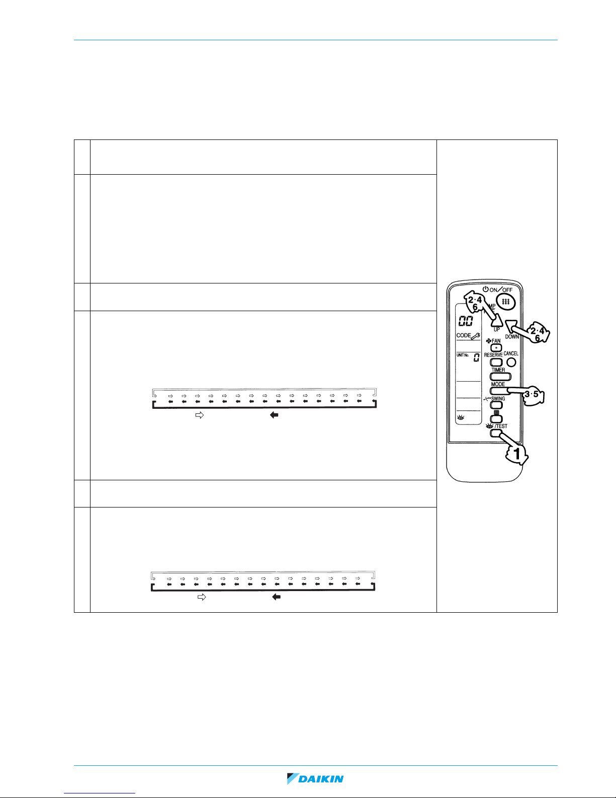
1.3. Wireless controller BRC4/7
1.3.1. Access to error code
If a unit stops due to an error, the operation indicating LED on indoor unit is blinking. The error code can be determined by following
the procedure described below.
1 Press the INSPECTION/TEST button to select “inspection”. The equipment enters the inspec-
tion mode. The “Unit” indication is displayed and the Unit No. display shows blinking “
tion.
2 Set the Unit No.
Press the UP or DOWN button and change the Unit No. display until the buzzer (*1) is generated
from the indoor unit.
*1 Number of beeps
3 short beeps: Conduct all of the following operations.
1 short beep: Conduct steps 3 and 4.
Continue the operation in step 4 until a buzzer remains ON. The continuous
buzzer indicates that the error code is confirmed.
Continuous beep: No abnormality.
3 Press the MODE selector button.
The left “
4 Error code upper digit diagnosis
Press the UP or DOWN button and change the error code upper digit until the error code matching buzzer (*2) is generated.
0” (upper digit) indication of the error code blinks.
0” indica-
The upper digit of the code changes as shown below when the UP and DOWN buttons are
pressed.
*2 Number of beeps
Continuous beep: Both upper and lower digits matched. (Error code confirmed)
2 short beeps: Upper digit matched.
1 short beep: Lower digit matched.
5 Press the MODE selector button.
The right “
6 Error code lower digit diagnosis
Press the UP or DOWN button and change the error code lower digit until the continuous error
code matching buzzer (*2) is generated.
The lower digit of the code changes as shown below when the UP and DOWN buttons are
No further information can be retrieved through the wireless controller BRC4/7.
0” (lower digit) indication of the error code blinks.
pressed.
23/09/16 Page 17
 Loading...