

Daikin FXFQ-PVJU, FXZQ-M7VJU, FXDQ-MVJU, FXMQ-PVJU, FXHQ-MVJU Engineering Data
...
EDUS 391000 - C
AMERICASAMERICAS
Controls

EDUS391000-C
Controls 1
Controls
1. Control Systems..........................................................................................2
2. Control Devices...........................................................................................3
2.1 BRC1E71 Navigation Remote Controller (Wired Remote Controller) .......... 3
2.2 BRC4C / 7C / 7E Wireless Remote Controller / Receiver .......................... 12
2.3 BRC2A71 Simplified Remote Controller..................................................... 14
2.4 DCS302C71 Central Remote Controller .................................................... 17
2.5 DCS301C71 Unified ON/OFF Controller.................................................... 40
2.6 DST301BA61 Schedule Timer ................................................................... 48
2.7 DCS601C71 intelligent Touch Controller ................................................... 55
3. Adapter......................................................................................................67
3.1 KRCS01-1B / 4B Remote Sensor .............................................................. 67
3.2 DTA104A53 / 61 / 62 External Control Adapter for Outdoor Unit
(Must be Installed on Indoor Units) ............................................................ 70
3.3 DTA109A51 DIII-NET Expander Adapter................................................... 73
3.4 KRP1C74 / 75 Wiring Adapter................................................................... 76
3.5 KRP4A71 / 72 / 73 / 74 Group Control Adapter) ........................................ 79
3.6 DCS302A72 Unification Adapter for Computerized Control....................... 84
Control Systems EDUS391000-C
2 Controls
1. Control Systems
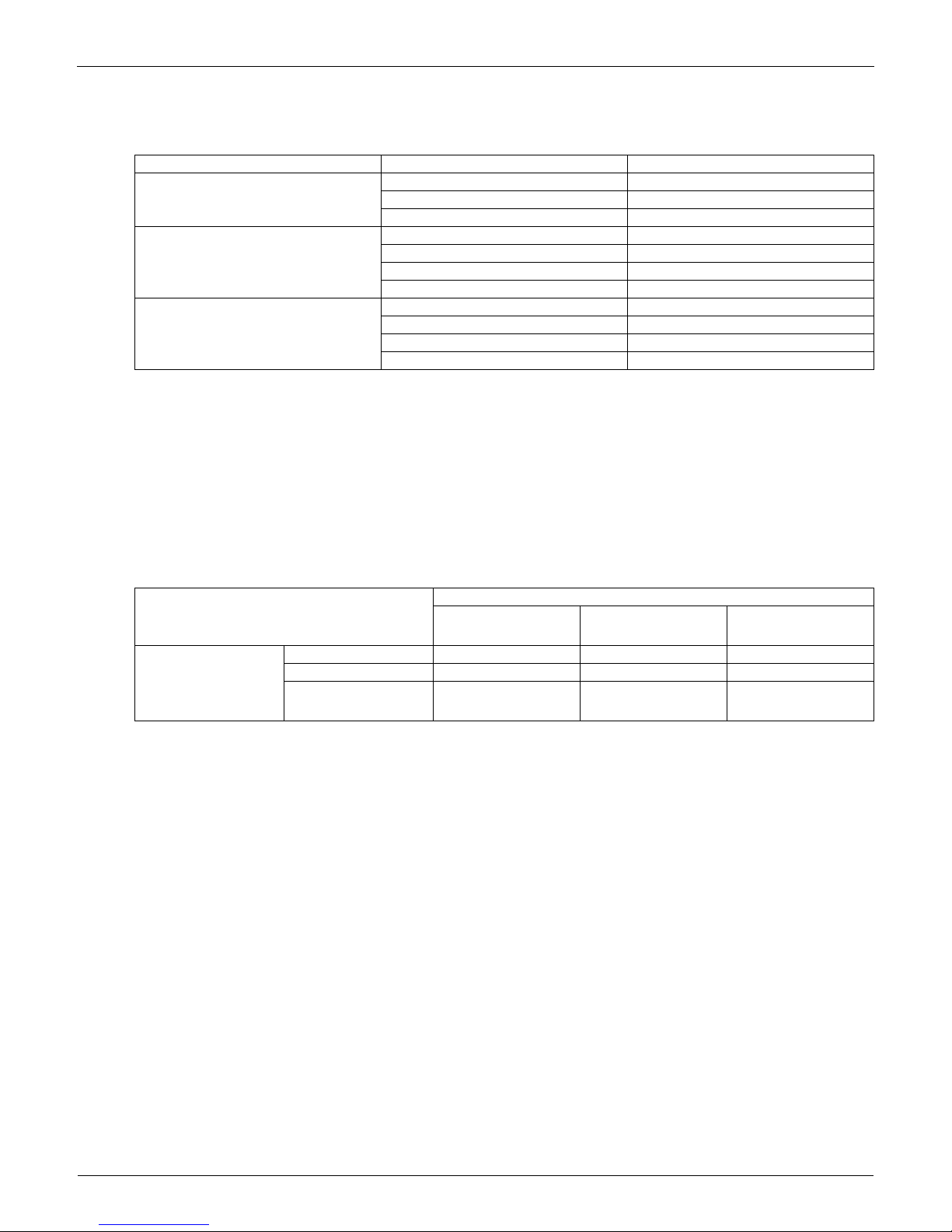
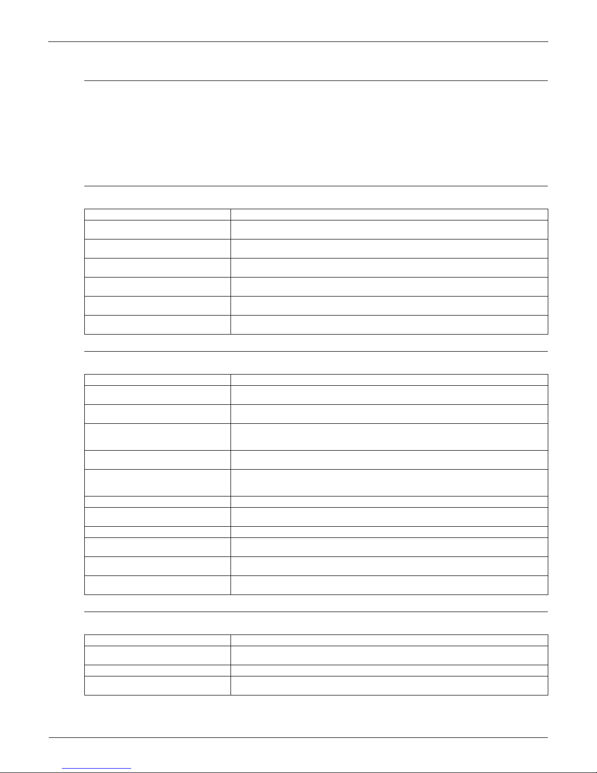
Optional Accessories of Operation Control System
Note:
1. Installation box (No. 4) is necessary for each adaptor marked with an asterisk.
2. Electrical box (No. 5-1/6-1) is required for controller (No. 5/6).
3. When using the BRC2A71, remote sensor KRCS01-1B/4B is needed.
If the temperature sensor in remote controller can not sense the accuracy temperature of the room, installation of the remote sensor
KRCS01-1B/4Binstallation is also recommended.
4. Only 2 fan speeds (H, L) are available.
Building Management System
Note:
1. BACnet® is a registered trademark of American Society of Heating, Refrigerating and Air-Conditioning Engineers (ASHRAE).
2. LON WORKS is a registered trade mark of Echelon Corporation.
No.
Type
Item
FXFQ-
PVJU FXZQ-M7VJU
FXDQ-MVJU FXMQ-PVJU
FXMQ-MVJU
FXHQ-MVJU FXAQ-MVJU
FXLQ-MVJU
FXNQ-MVJU
FXTQ-PAVJU
1 Remote controller
Wireless
BRC7C812 — BRC4C82
BRC4C82
(Note 4)
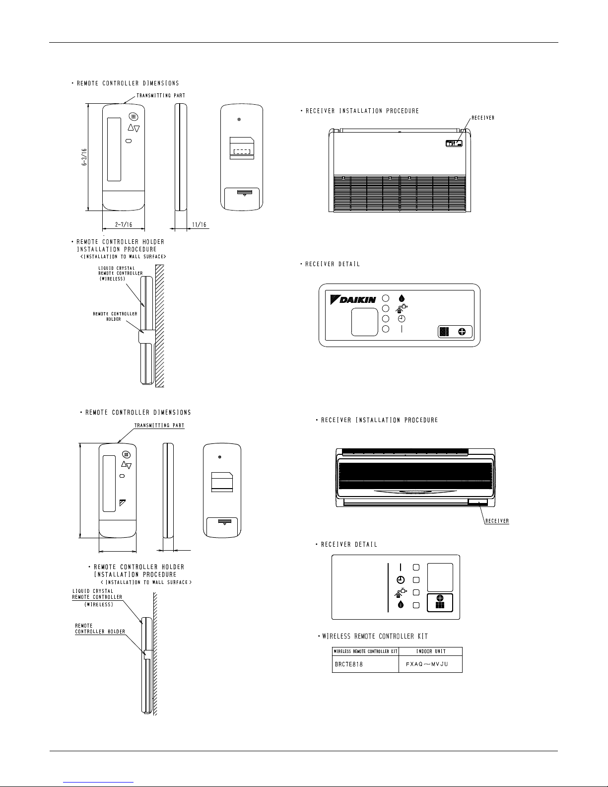
BRC4C82 BRC7E83 BRC7E818 —
Wired
BRC1E71
2 Simplified remote controller
— BRC2A71 — BRC2A71
BRC2A71
3 Remote sensor (Note 3)
KRCS01-4B
KRCS01-1B
KRCS01-4B KRCS01-1B KRCS01-4B
4 Installation box for adaptor PCB
KRP1H98 KRP1B101
KRP4A96
— KRP1C93 KRP4A93 — KRP1B101
5 Central remote controller
DCS302C71
5-1 Electrical box
KJB311AA
6 Unified ON/OFF controller
DCS301C71
6-1 Electrical box
KJB212AA
7 Schedule timer
DST301BA61
8 External control adaptor for outdoor unit
DTA104A62
DTA104A53
DTA104A61
DTA104A61
DTA104A62
— DTA104A61
DTA104A53
9 DIII-NET expander adaptor
DTA109A51
10 Wiring Adapter
KRP1C75 KRC1C74 KRP1C74 KRP1C74 —
KRP1C74
KRC1C75
11 Group Control Adapter
KRP4A73 KRP4A74 KRP4A71
KRP4A71
KRP4A72 KRP4A71
KRP4A71
KRP4A74
C: 3D043022F
C: 3D068551
C: 3D068222A
C: 3TW30729-6
Part name Model No. Function
intelligent Touch
Controller
Basic
Hardware
intelligent
Touch
Controller
DCS601C71 • Air-Conditioning management system that can be controlled by a compact all-in-one unit.
Option
DIII-Net Plus
Adapter
DCS601A72 • Add another DIII-Net line on DCS601C71.
Software
PPD DCS002A71 • Power Proportional Distribution.
Web/Email DCS004A71
• Monitors and controls the air conditioning system using the Internet and Web browser
application on a PC.
HTTP DCS007A51 • HTTP interface option for Home Automation System integration.
Communication
Line
Interface for use in BACnet®2 DMS502B71
Interface unit to allow communications between VRV and BMS. Operation and monitoring of
VRV systems through BACnet® communications.
Optional DIII board DAM411B51
Expansion kit, installed on DMS502B71, to provide 2 more DIII-NET communication ports. Not
usable independently.
Interface for use in L
ON WORKS
3 DMS504C71
Interface unit to allow communications between VRV and BMS. Operation and monitoring of
VRV systems through L
ON WORKS
communication.
Contact/Analog
signal
Unification adaptor for computerized
control
DCS302A72 Interface between the central monitoring board and central control units
Group Control Adapter KRP4A71-74
To control the group of indoor units collectively, which are connected by the transmission wiring
of remote controller.
External control adapter for outdoor unit
(Must be installed on indoor units.)
DTA104A53, 61, 62Cooling/Heating mode changeover. Demand control and Low noise control are available
between the plural outdoor units.
EDUS391000-C Control Devices
Controls 3
2. Control Devices
2.1 BRC1E71 Navigation Remote Controller (Wired Remote Controller)
2.1.1 Features
· Clear Display.............................Equipped with backlight and large sized character display and buttons.
· Stylish........................................Basic tone is white and arrow keys are located at the center.
· Simple Operation ......................Simple operation used with arrow keys and menu-driven method.
· Multilingual Display ...................Available for selection of 3 languages
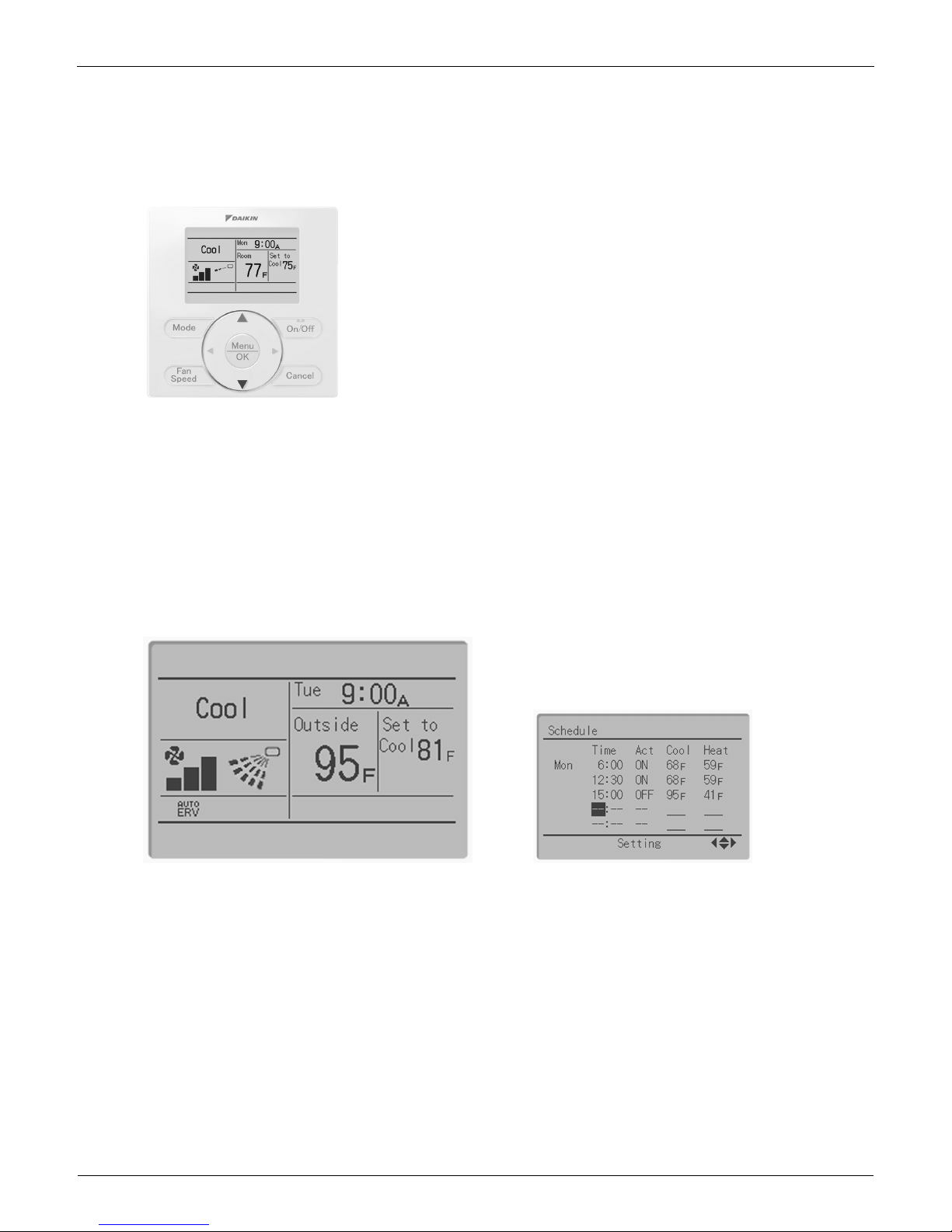
· Other Features ..........................Wide variety of functions to meet customer needs such as schedule setting.
Clear Display
Dot matrix display
A combination of fine dots enables texts and icons to be displayed smoothly and makes the display of a wide variety of text and
illustrations possible.
Backlight display
Newly equipped backlight enables operation in dark room.
BRC1E71
Control Devices EDUS391000-C
4 Controls
Stylish
Simple and Functional Design
Simple Operation
Compared to the conventional structure of button allocation for each function, the number of buttons has been decreased (from 15 to 9).
Can intuitively handle frequently performed basic operations.
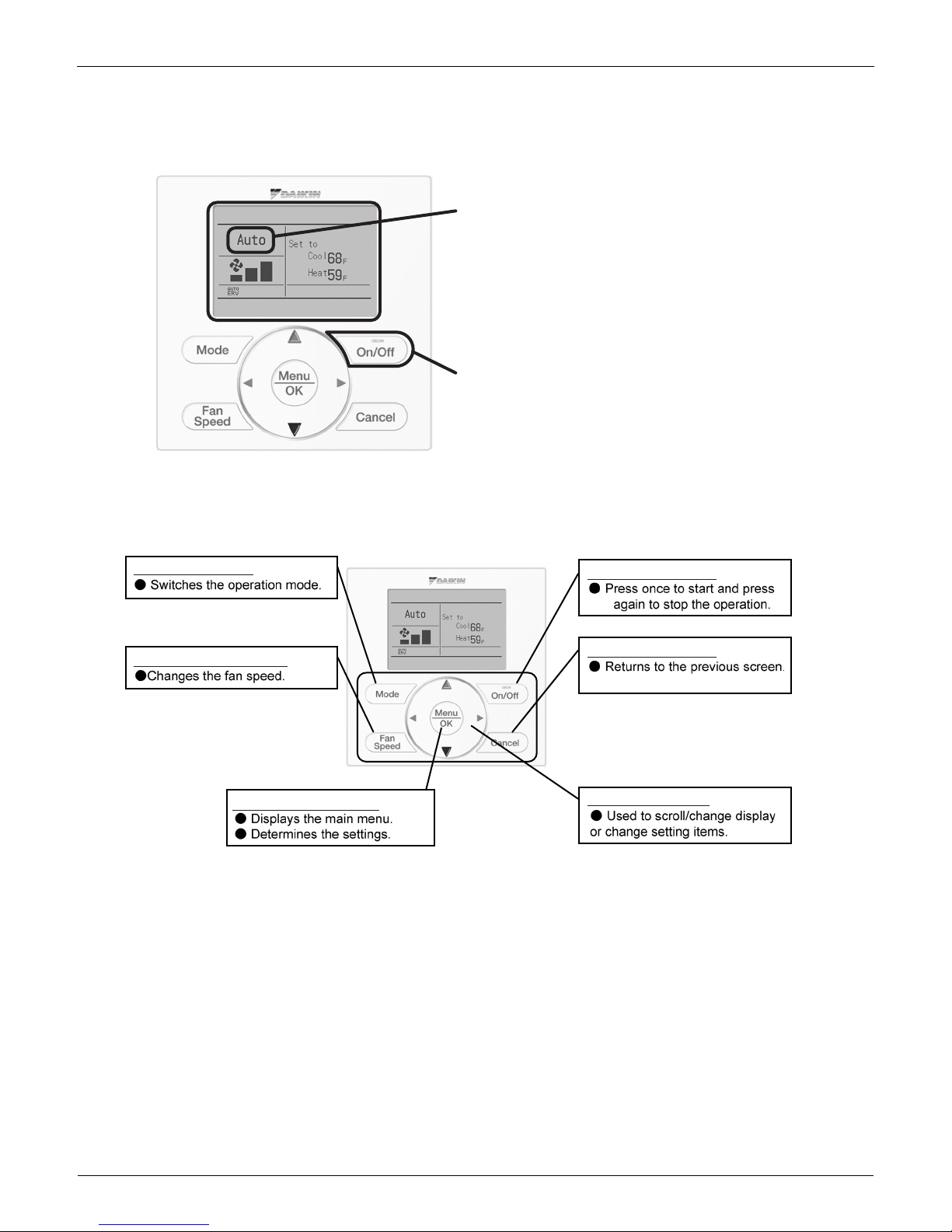
(1) Large text display (2) Large buttons (3) Backlight (4) No-cover design
(1)
(2)
(3)
(1) "Mode" button
(3) "Menu/OK" button
(6)-(9) Arrow Keys
(5) "Cancel" button
(4) "On/Off" button
(2) "Fan Speed" button
EDUS391000-C Control Devices
Controls 5
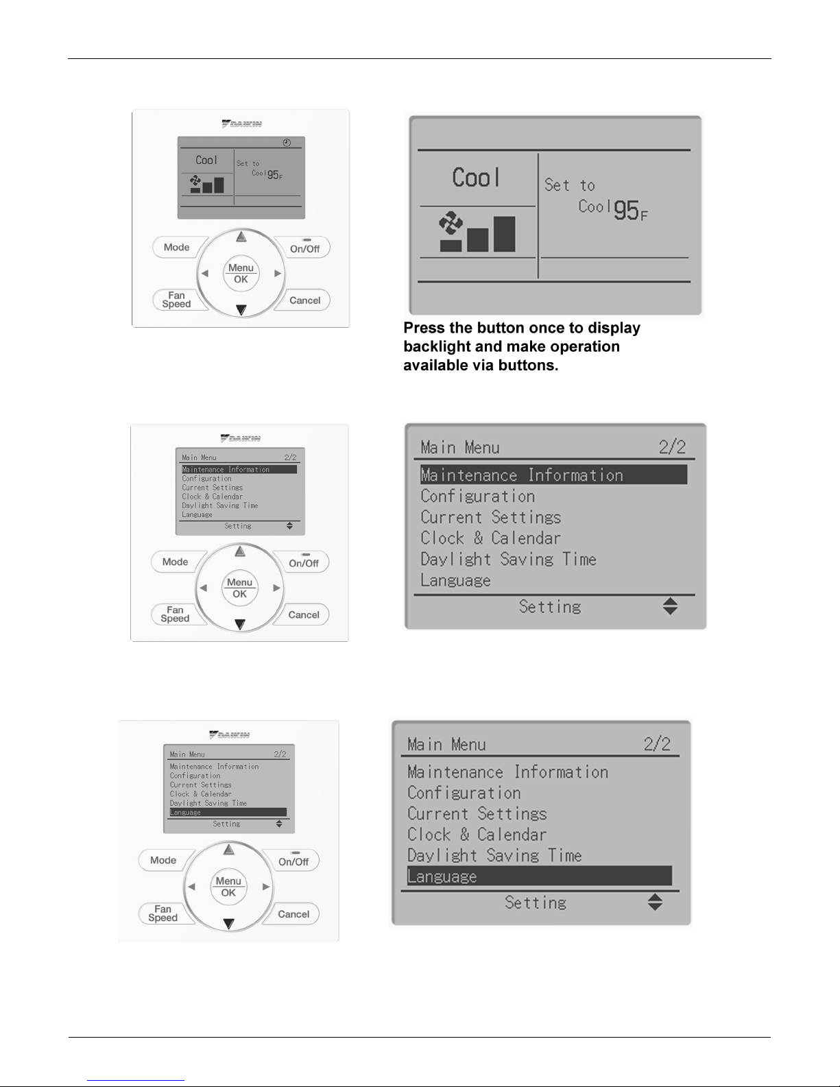
Available for simple operation with arrow keys and menu-driven system.
Available for simple operation with arrow keys and menu-driven system.
Available for simple operation with arrow keys and menu-driven system.
Press "Menu/OK" button to change the
screen and then the main menu appears.
Select the item you wish to set with direction
keys and press "Menu/OK" button at the item
you wish to set and the setting entry screen
appears.
Control Devices EDUS391000-C
6 Controls
Available for simple operation with arrow keys and menu-driven system.
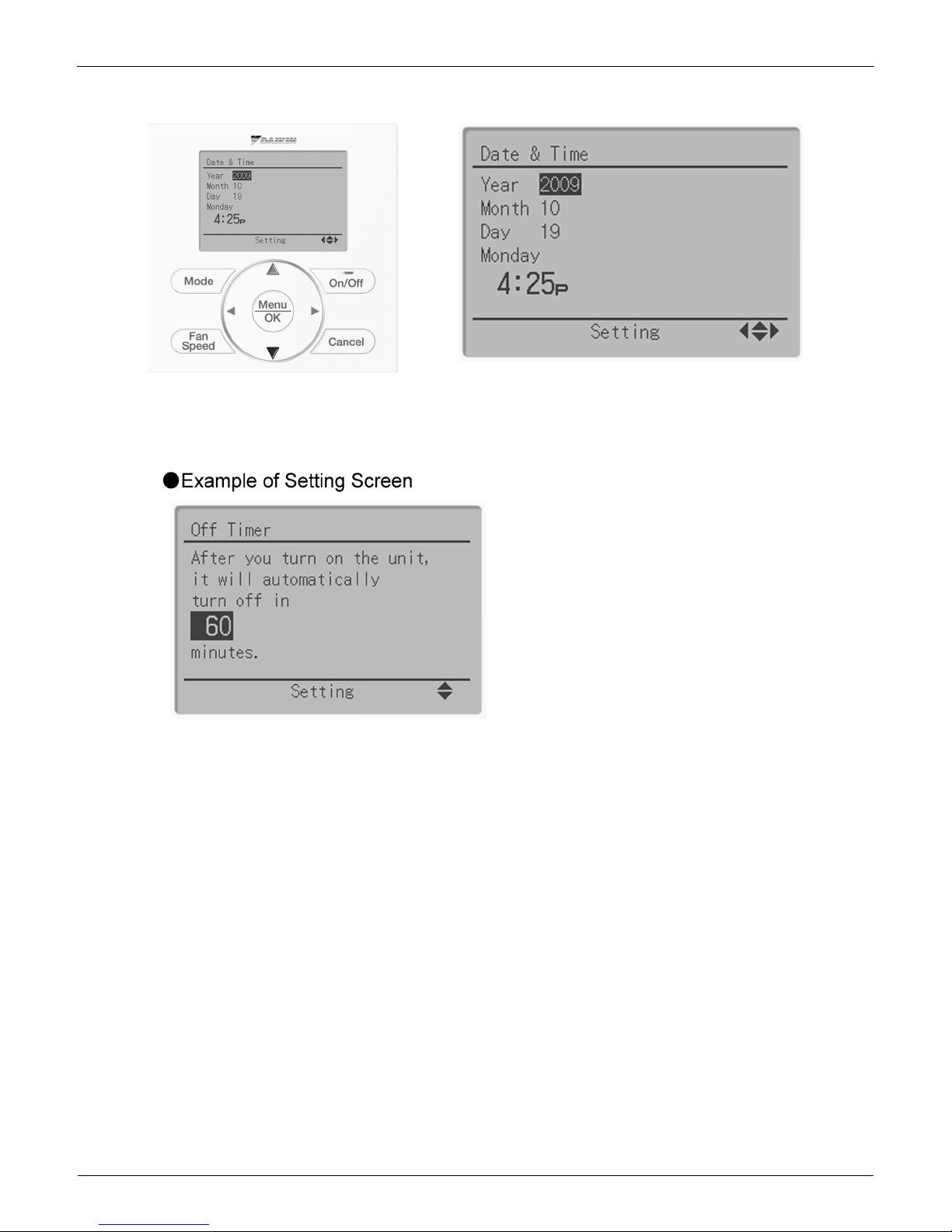
Guide on display
The item you wish to set can be changed
with up or down button.
The display gives an
explanation of each setting
for easier operation.
EDUS391000-C Control Devices
Controls 7
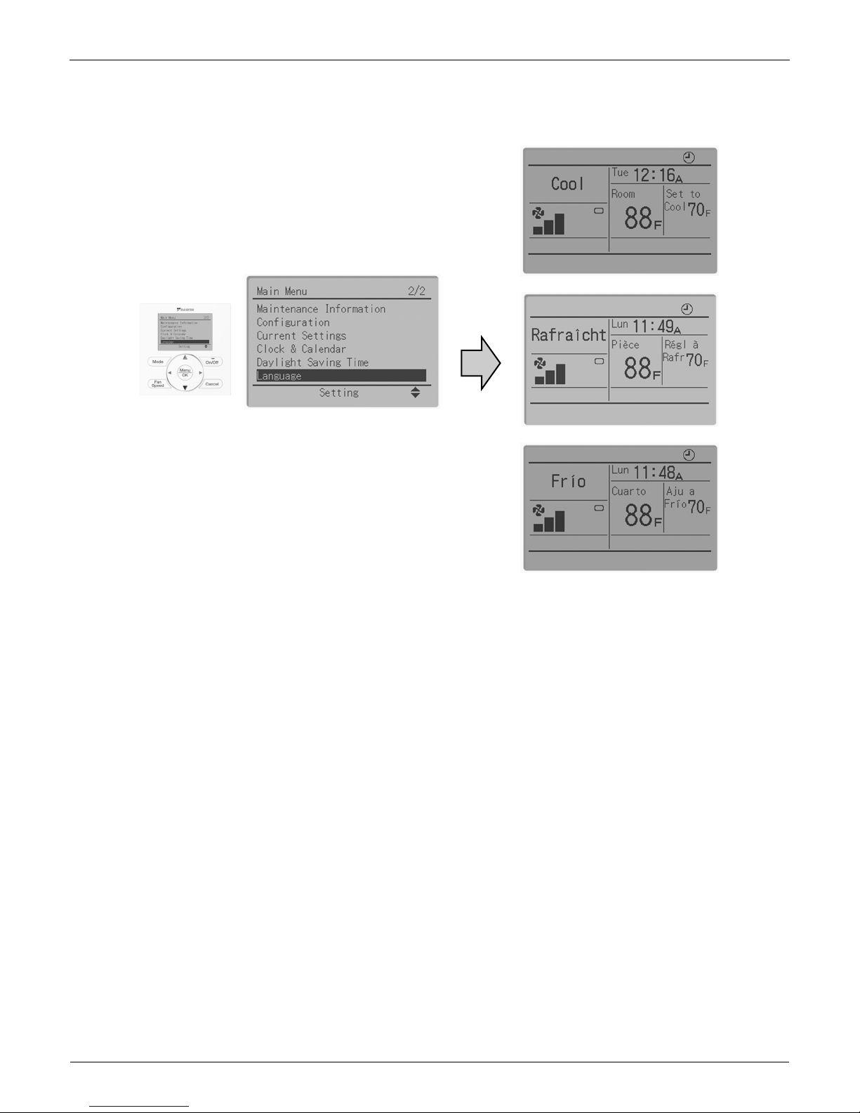
Multilingual Display
Available for display in 3 different languages.
Always available for switching display by selecting from main menu.
3 languages (English, French, Spanish)
Control Devices EDUS391000-C
8 Controls
Other Features
EDUS391000-C Control Devices
Controls 9
2.1.2 Functions
Functions
: Possible
*1 Used for setting Standard Display mode or Detailed Display mode.
*2-1 When an error occurs, the error code blinks and the contact address and model names appear.
2-2 The contact address must be registered when the controller is installed.
2-3 For some models, model codes are displayed instead of model names.
*3 Can display for some model only.
*4 Setback function
Restrictions
1. In the case of two remote control system.
:Connectable ×:Not connectable
Due to the limited power supply capacity, there are some restrictions when controlling 2 remote controllers.
<Common restriction for SkyAir and VRV>
When controlling one indoor unit with 2 remote controllers, the remote controller operated first turns the backlight on.
When controlling 2 remote controllers, the following functions cannot be set with the sub remote controller.
1. Schedule function and Setback temperature function
2. Auto Changeover function by the remote controller
<Restriction for VRV only>
Adaptor for wiring (KRP1C*) or power supply adaptor for indoor unit PCB (X18A or X35A) cannot be used for 2 remote
controller system.
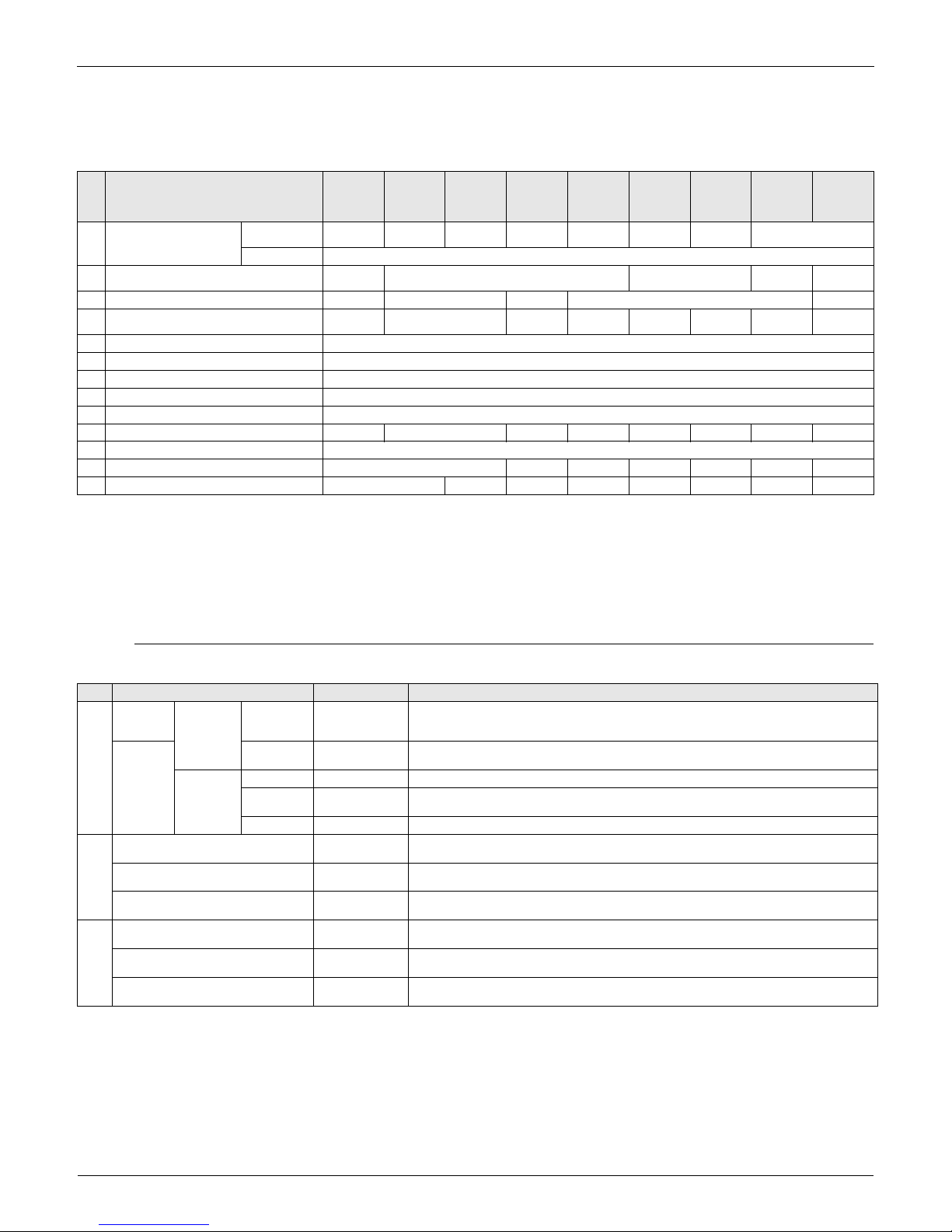
Category Function BRC1E71
Basic Functions
Drawing display LCD
Operation method Menu selection
Backlight function
Convenient Functions
Clock function (time display)
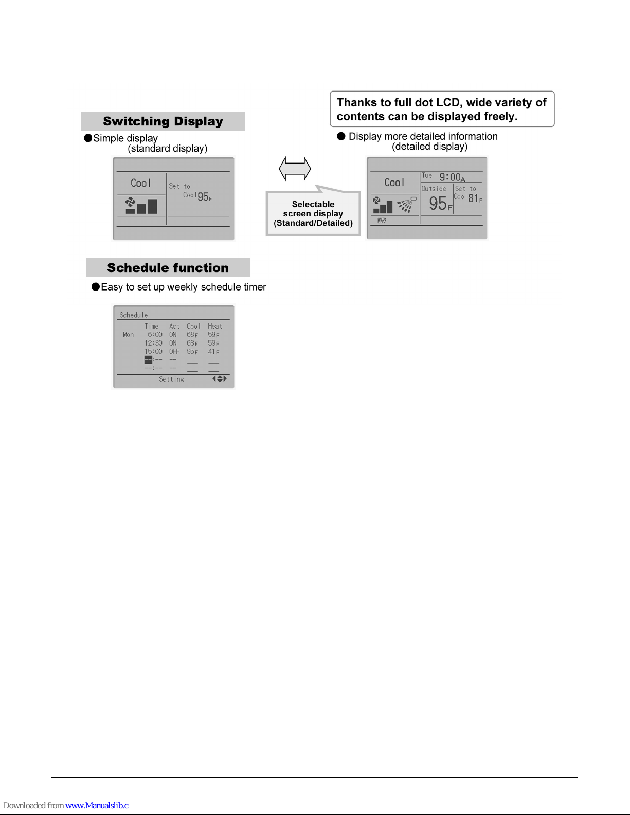
Display switch function
*1
Keylock function
Schedule (weekly) timer*4
Maintenance/Services
Model name display
*2
Contact dealer display
*2
Operation time display
*3
Operational data display
*3
Main
BRC1E71 BRC1D71
Wireless
BRC4***
BRC7***
Sub
BRC1E71 ××
BRC1D71 ×
Wireless
BRC4***
BRC7***
× ×
Control Devices EDUS391000-C
10 Controls
2. In the case of centralized remote controller connection.
When connecting a centralized related device (*1), the following functions cannot be set.
1. Schedule function and Setback temperature function
2. Auto Changeover function by the remote controller
(*1) this means all centralized remote controller.
intelligent Touch Controller [DCS601C71]
intelligent Manager [DAM602A71,72]
BACnet Gateway [DMS502B71]
Central remote controller [DCS302C71]
Unified ON/OFF controller [DCS301C71]
Schedule timer [DST301BA61]
Residential central remote controller [DCS303A71]
Wiring adaptor for electrical appendices [KRP2A5*/6*]
DMS-IF [DMS504C71]
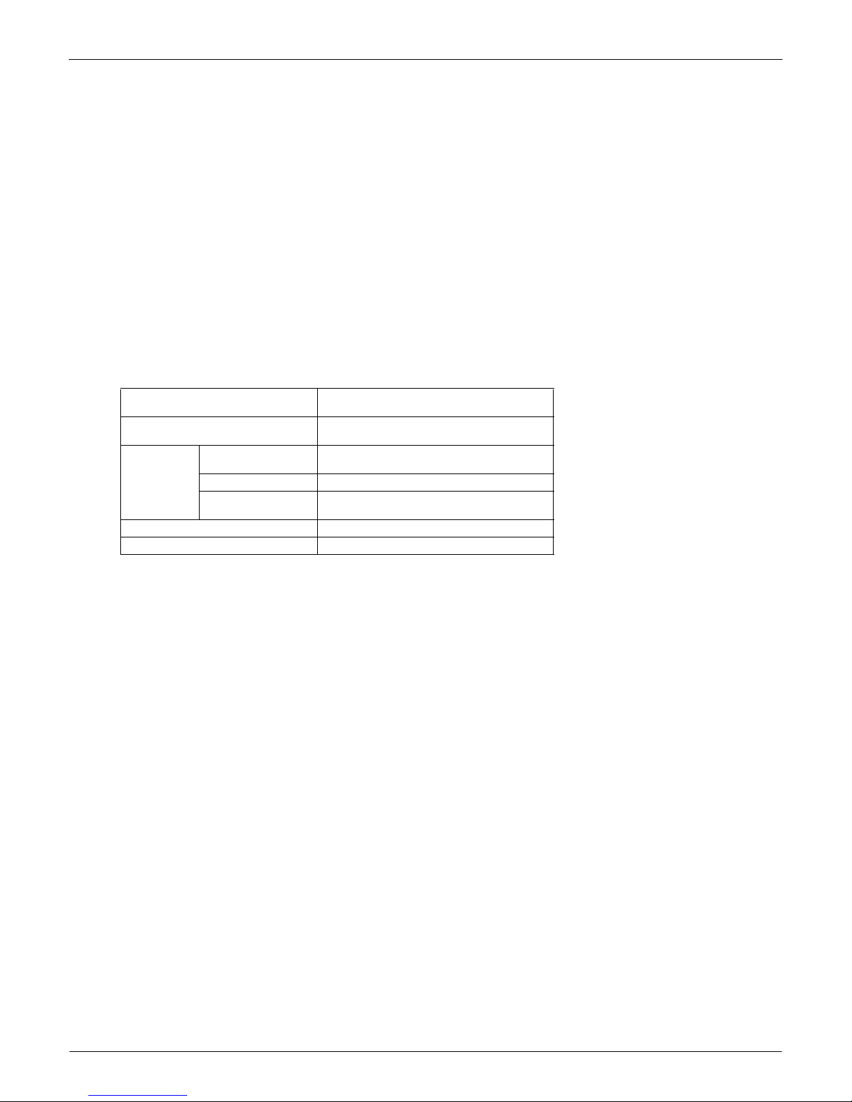
2.1.3 Specifications
New Remote Controller
BRC1E71
Dimension (in.)
H × W × D
4’3/4” × 4’3/4” × 3/4”
LCD
Display size (in.)
H × W
1’25/32” × 2’13/16”
Display method Full dot method (dot 160 × 255)
Backlight
Yes
(Background color: white)
Color Fresh white
Cover for operation part No
EDUS391000-C Control Devices
Controls 11
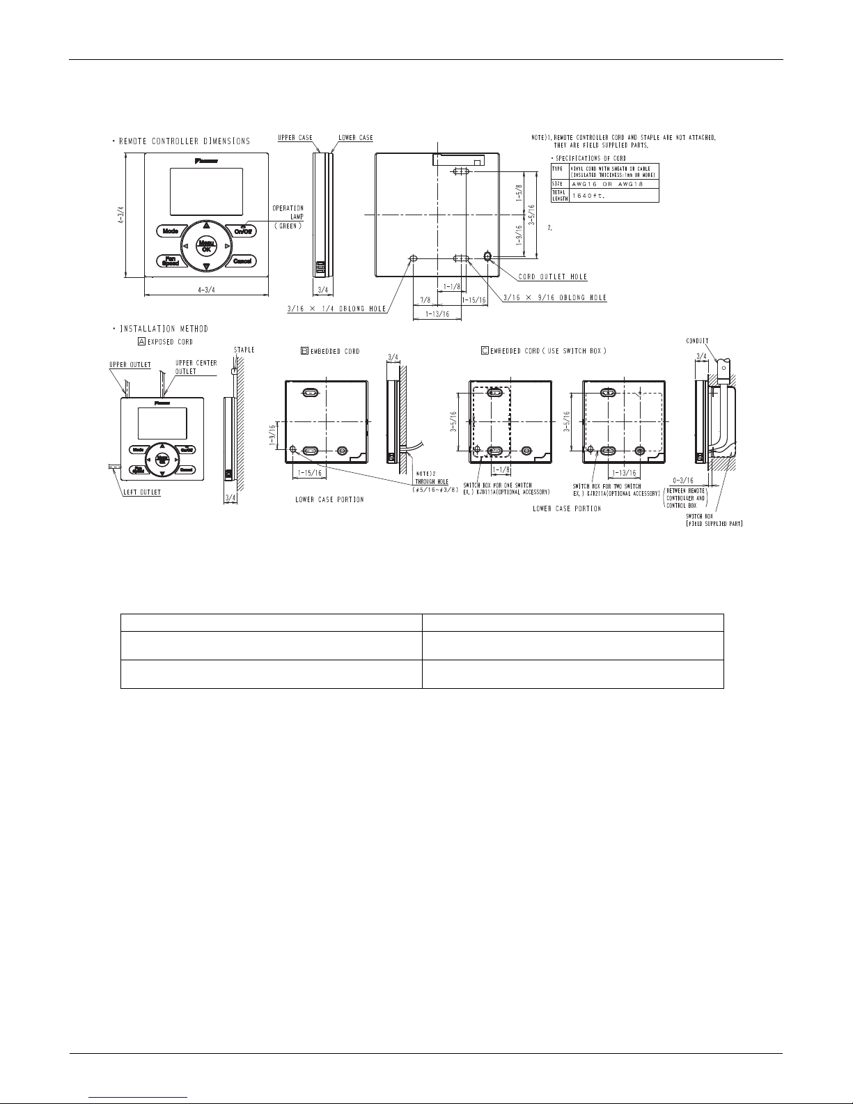
2.1.4 Dimensions
2.1.5 Applicable Models
Applicable Models
3D065275
Unit (in.)
IF THE HOLE SIZE IS TOO LARGE OR THE LOCATION NOT PROPER,
THE WIRE MAY COME OUT OF THE HOLE IN THE REMOTE CONTROLLER.
Applicable Indoor unit
VRV
All models that can be connected
BRC1D71
SkyAir
All models that can be connected
BRC1D71
Control Devices EDUS391000-C
12 Controls
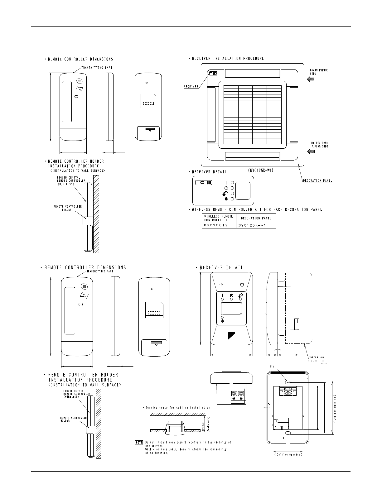
2.2 BRC4C / 7C / 7E Wireless Remote Controller / Receiver
BRC7C812
BRC4C82
C:3D005912D
2-7/16 11/16
6-3/16
Unit (in.)
C:3D007898B
2-7/16 11/16
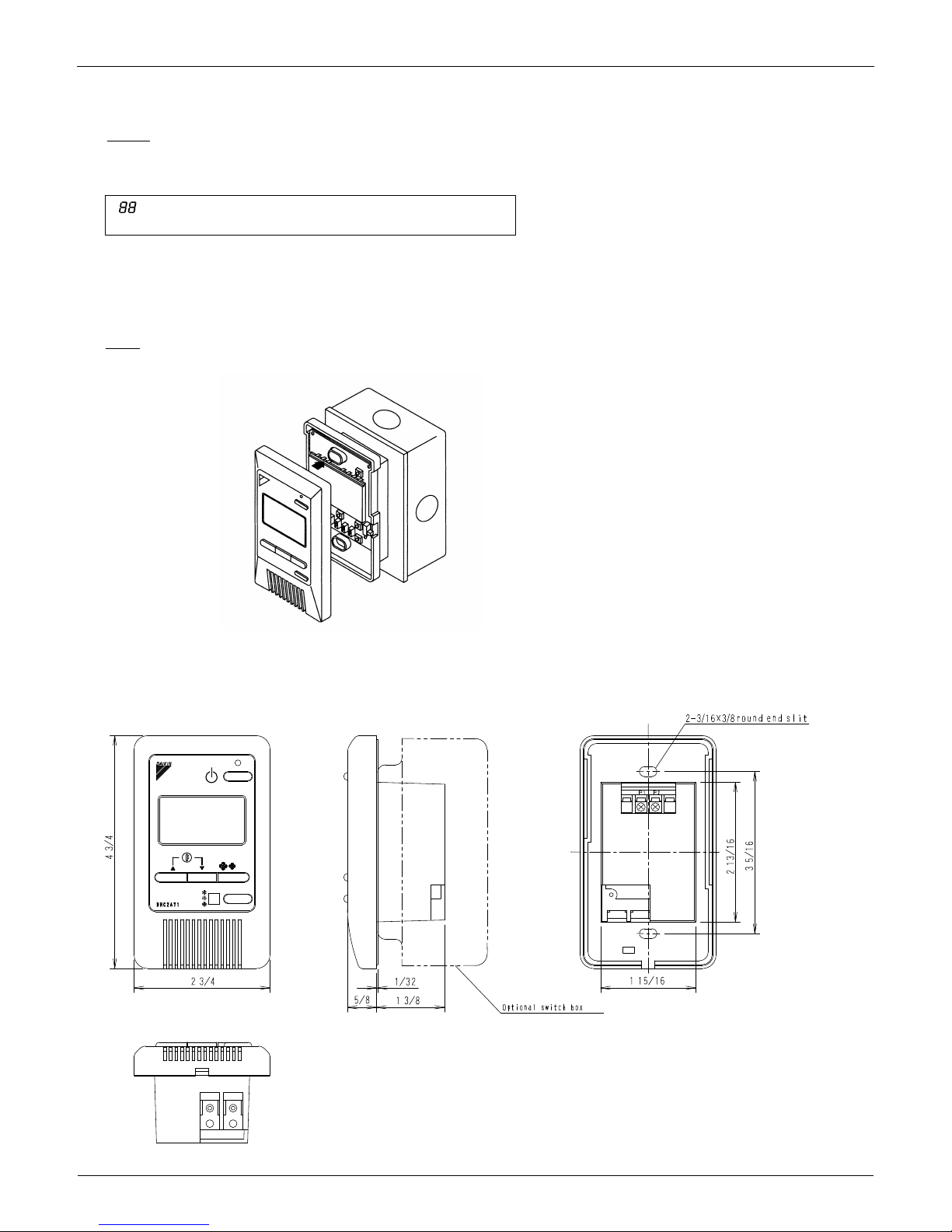
2-3/4
2-3/16×3/8
11/16
1-3/8
1-15/16
3-9/16
1/32
6-3/16
4-3/4
2-13/16
3-5/16
4-3/16
Unit (in.)
EDUS391000-C Control Devices
Controls 13
BRC7E83
BRC7E818
3D049336
Unit (in.)
C:3D034905B
2-7/16
11/16
6-3/16
Unit (in.)
Control Devices EDUS391000-C
14 Controls
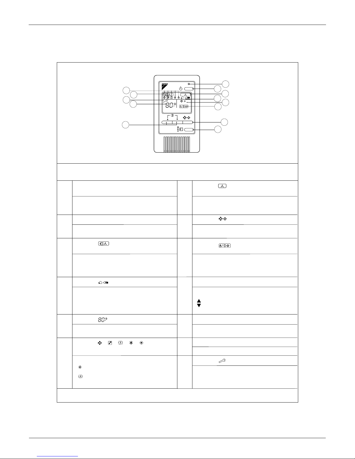
2.3 BRC2A71 Simplified Remote Controller
2.3.1 Name and Function
DISPLAY Ò Ó (CHANGEOVER UNDER
CONTROL)
DISPLAY Ò Ó (VENTILATION/AIR
3P146204
REMOTE CONTROLLER: NAME AND FUNCTION OF EACH SWITCH AND DISPLAY
ON/OFF BUTTON
Press the button and the system will start. Press the
button again and the system will stop.
OPERATION LAMP (RED)
The lamp lights up during operation. Blinks in case of stop
due to malfunction.
It is impossible to changeover heating/cooling with the
remote controller when it shows this display. (As for details,
see “SETTING OF MASTER REMOTE CONTROLLER” in
the installation manual attached to the indoor unit.)
DISPLAY “ ” (UNDER CENTRALIZED
CONTROL)
When this display shows, the system is UNDER
CENTRALIZED CONTROL.
(This is not a standard specification)
This display shows that the total heat exchanger and the
air cleaning unit are in operation. (These are optional
accessories).
DISPLAY “ ” (SET TEMPERATURE)
This display shows the set temperature. Only given during
a cooling or heating operation.
DISPLAY “ ” “ ” “ ” “ ” “ ”
(OPERATION MODE)
This display shows current OPERATION MODE.
“ ” is not available with outdoor units specially designed
for cooling only.
“ ” is reserved only for outdoor units capable of heat
recovery.
DISPLAY “ ” (DEFROST / HOT START)
Indicates that defrost or hot start (during which the fan is
stopped till the temperature of air supply rises enough at
the start of a heating operation) is in progress.
TEMPERATURE SETTING BUTTON
Use this button for SETTING TEMPERATURE of the
thermostat.
; Each press raises the set temperature by 1 ˚F.
; Each press lowers the set temperature by 1 ˚F.
The variable temperature range is between 60 F and 90 ˚F.
FAN SPEED CONTROL BUTTON
Press this button to select the fan speed, HIGH or LOW,
of your choice.
OPERATION MODE SELECTOR BUTTON
Press this button to select OPERATION MODE.
DISPLAY “ ” (MALFUNCTION)
Indicates malfunction and blinks if the unit stops operating
due to malfunction.
(As for details, see “TROUBLE SHOOTING” in the
operation manual attached to the outdoor unit.)
DISPLAY “ ” (FAN SPEED)
This display shows the fan speed: HIGH or LOW.
For the sake of explanation, all indications are shown in the figure above contrary to actual running situations.
6
3
13
5
10
12
11
9
8
4
7
1
2
F
HL
F
BRC2A71
H L
EDUS391000-C Control Devices
Controls 15
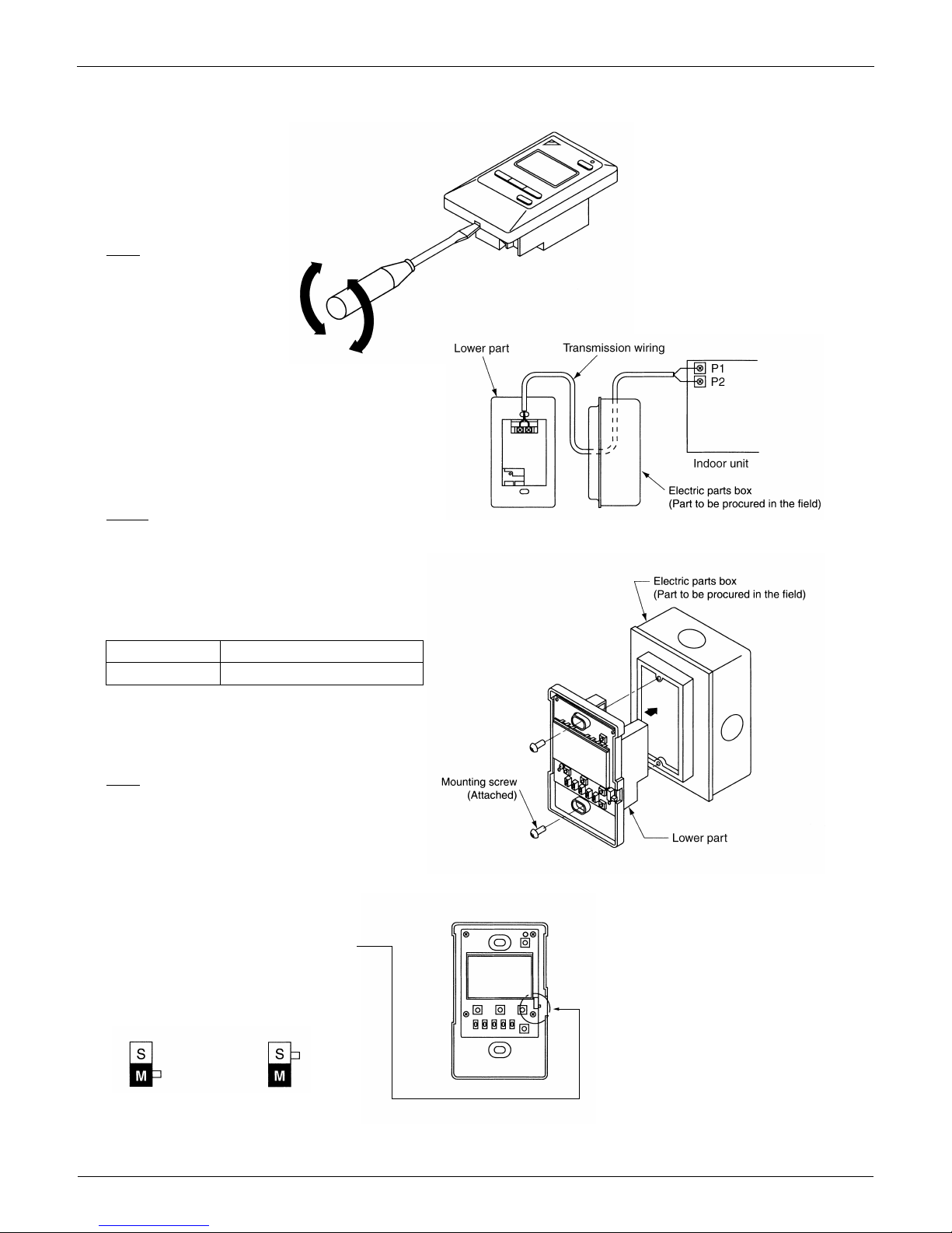
2.3.2 Installation
3P146205-1
1. Remove the upper part of remote controller.
Insert a minus screwdriver into the
slot between the upper and the
lower part of remote controller.
NOTE
1. Do not directly touch the PC
board with your hand.
2. Wire the indoor unit.
Connect terminals P1 and P2 on the rear of
the lower part of remote controller to
terminals P1 and P2 on the indoor unit.
(Terminals P1 and P2 have no polarity.)
3. Fasten the remote controller.
Attach the lower part of remote controller to the electric parts box
(part to be procured in the field).
NOTE
Choose the flattest place possible for the mounting surface. Be
careful not to distort the shape of the lower part of remote controller
by over-tightening the mounting screws.
For the electric parts box to be procured in the field, use optional
accessories KJB111A.
NOTES
1. The electric par ts box and wiring for connection are not included.
2. When wiring, run the wiring away the power supply wiring in order to
avoid receiving electric noise (external noise).
3. When wiring, refer to the wiring diagram of indoor unit (attached to
indoor unit) as well.
WIRING SPECIFICATION
Wiring type
Size
Sheathed wire (2 wire)
AWG18 or AWG16
4. Initial setting
Change the MAIN/SUB changeover switch
setting as described below.
If controlling one indoor unit with two remote
controllers, set one remote controller to
"
MAIN." and the other to "SUB.
"
Main Remote
Controller
(Factory Set)
Sub Remote
Controller
Control Devices EDUS391000-C
16 Controls
2.3.3 Dimensions
5. Reattach the upper part of remote controller.
NOTE
1. Do not directly touch the PC board with your hand.
NOTES
2If controlling with one remote controller, be sure to set it to
"MAIN."
2Set the remote controller before turning power supply on.
" " is displayed for about one minute when the power supply is
turned on, and the remote controller cannot be operated in some cases.
3P146205-2
3D047341
Unit (in.)
EDUS391000-C Control Devices
Controls 17
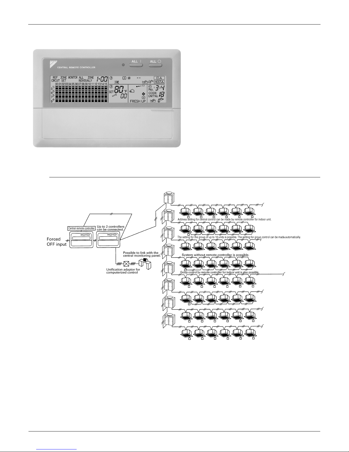
2.4 DCS302C71 Central Remote Controller
2.4.1 System Configuration
System Outline
You can connect up to 64 groups of indoor units (max.
128 units); let’s you operate or monitor ON/OFF,
temperature setting, etc., by zone individually or
together.
Up to 2 units are connectable within 1 system (Up to 4
units in case of the double central control mode)
Executes zone control for up to 64 zones and is
designed for operation efficiency.
Error contents are displayed in code; maintenance and
inspections can be quickly carried out.
1 schedule timer and up to 4 unified on/off controllers
can be connected to a single unit, and you can freely
extend the central control system according to building
size and purpose.
Applicable wiring methods include bus and star in
addition to series wiring
Control Devices EDUS391000-C
18 Controls
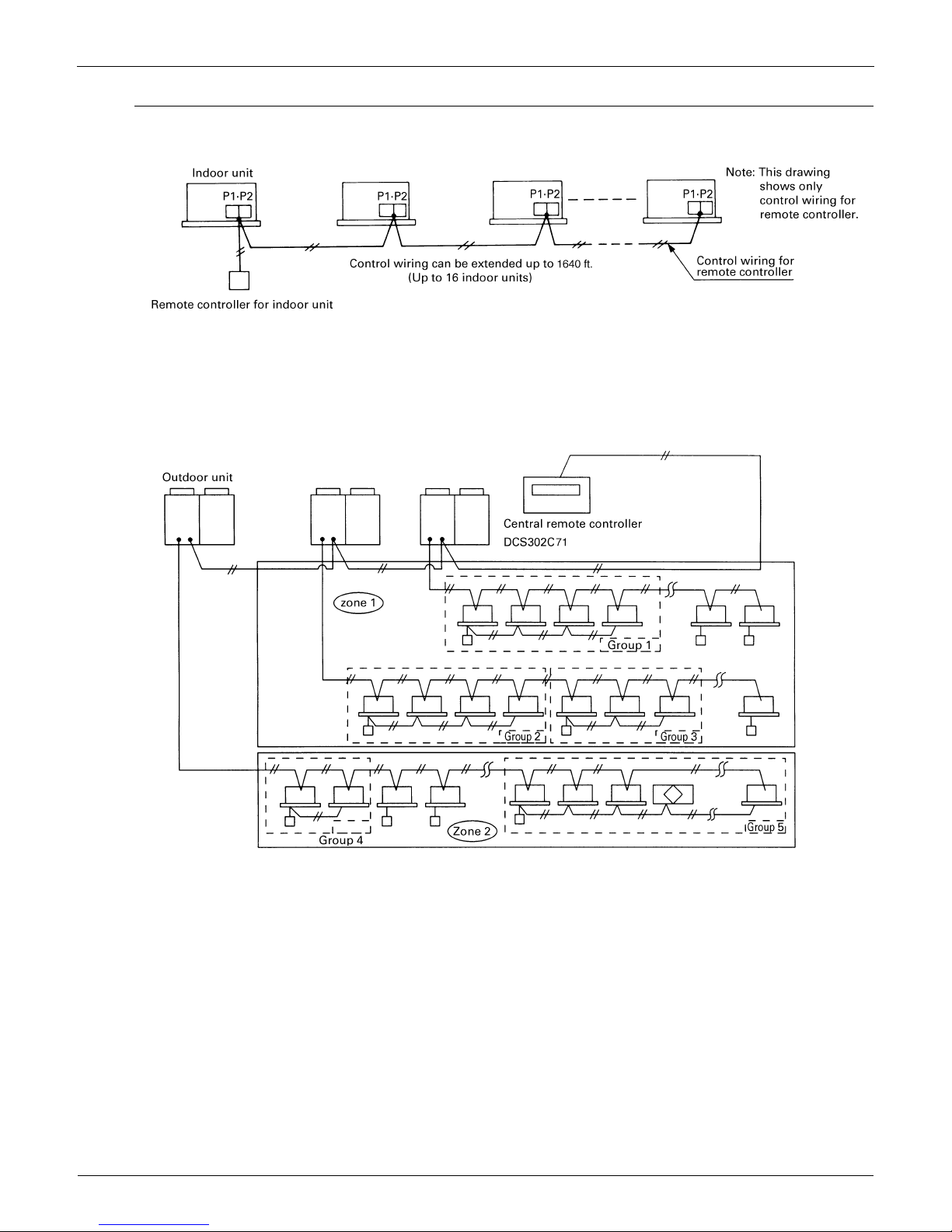
System Configuration (Group / Zone Control)
Group control
The group means the indoor units connected by the same control wiring for remote controller (connected to terminal
P1 and P2) and all the unit in group have “the same setting” and “the same operation”.
The indoor units in the group are controlled by the remote controller for indoor unit.
The number of indoor units in one group is up to 16 units.
Zone control
The zone means the indoor units connected by the same control wiring for central remote controller (connected to
terminal F1 and F2) and all the unit in zone have “the same setting”.
The zone control of the indoor unit is operated by the central remote controller.
From 1 up to 64 zones can be controlled by the central remote controller.
The number of groups you can set in one zone is from 1 up to 64 groups.
Up to 16 units can be set in one group, and up to 64 groups (up to 128 units) can be connected.
EDUS391000-C Control Devices
Controls 19
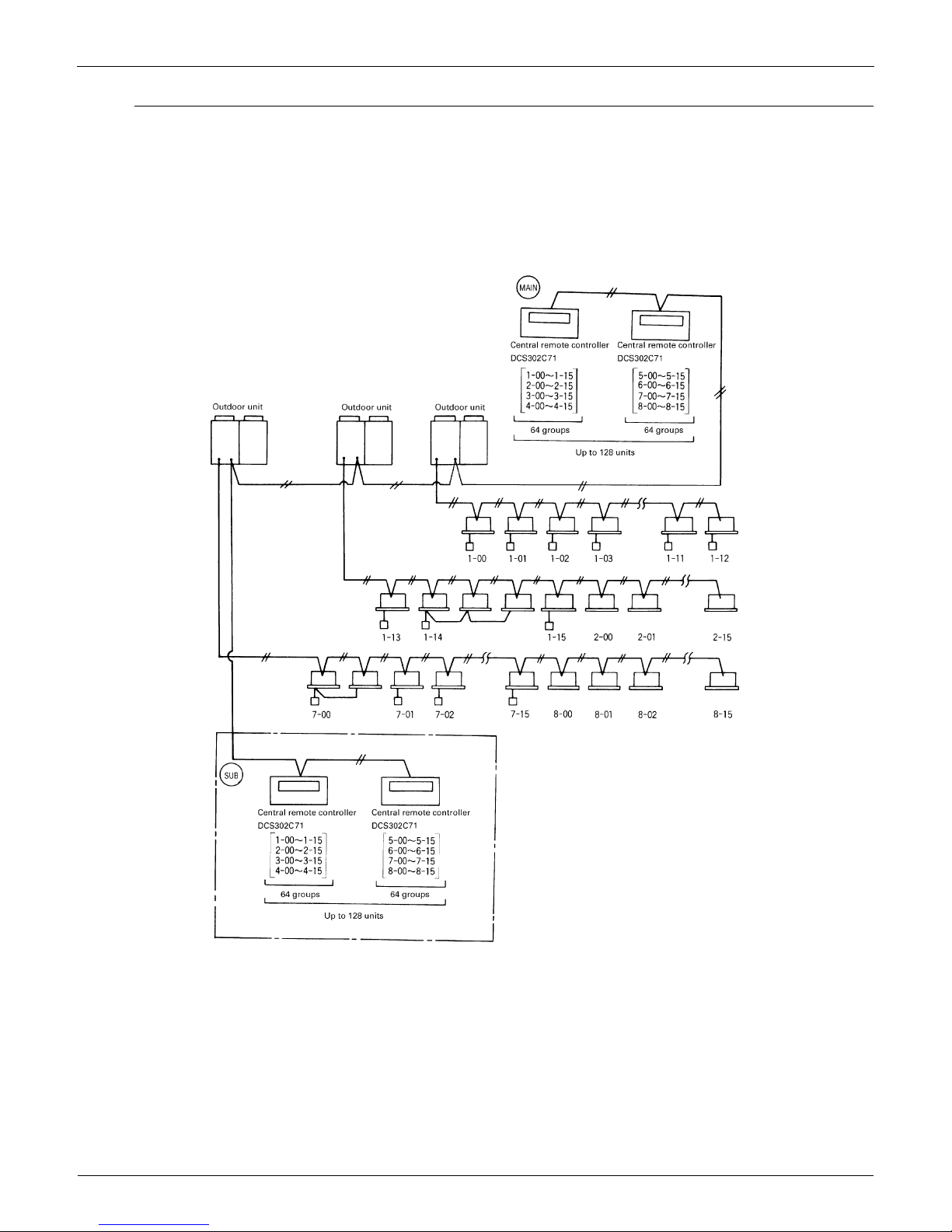
System Configuration (Control by 2 central remote controllers)
Up to 128 indoor units can be connected in one system.
2 or 4 central remote controllers are required. It is possible to control the same unit from 2 locations.
Up to 16 unified ON/OFF controllers can be connected. (8 controllers × 2 locations)
One schedule timer can be connected.
Notes:
1.Electrical power should be supplied to each central remote controller. (Single phase 100~240V)
2.When you control by 2 central remote controllers, be sure to set SS3 by the initial setting.
(
) When you control by 2 central remote controllers. (Last command priority)
Notes:
The following setting cannot be made by the sub side. Be sure to set by the main side.
Operation code setting
Control Devices EDUS391000-C
20 Controls
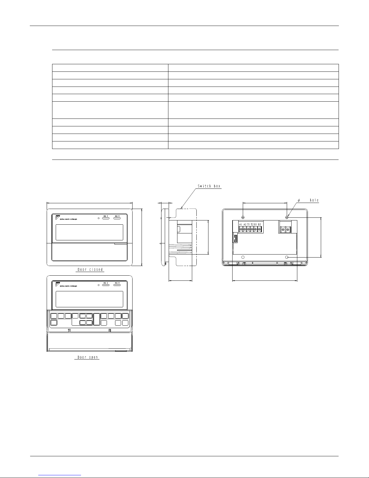
2.4.2 Specifications / Dimensions
Specifications
Dimensions
DCS302C71
DCS302C71
Power supply voltage / frequency AC100~240V ±10% 50/60Hz
Power consumption Max. 8W
Setting data backup Non-volatile memory (Data preserved semi-permanently)
Effects of instantaneous power failure No effect for 20 mili-sec. or less
Forced OFF input
Operation on the local side cannot be carried out
during forced OFF input.
No-voltage normal open contact
Micro-current contact capable of handling 16VDC and approx. 10mA.
Max. 492 ft cable length
Power supply for schedule timer Power can be supplied to schedule timer. (Max. 1 unit)
Operating ambient temperature /humidity condition -5~40°C, 95% RH or less (no condensation)
Size (width × height × depth) 7 1/8×4 3/4×2 9/16 exposed portion of front panel: 5/8 (Unit: Inch)
Machine Weight (Mass) Approx. 0.95 lbs
Unit (in.)
7 1/8
5/8 3 5/8
3/16
5 3/8
3 5/16
1 15/16
4 3/4
2 13/16
C:3D043353

EDUS391000-C Control Devices
Controls 21
2.4.3 Names and Functions of Operating Part
Display part DISPLAY (OPERATION MODE) Displays operating state.
Control Section
ALL
OPTION
L
NOTT
AVAILABLE
SETSET
FRESH UP
H
HH
No..
CODE
UNIT No.
TEST
INDIVIDUALLY
C
F
12
DISPLAY(VENTILATION
CLEANING DISPLAY)
This is displayed when a Ventiair
total enthalpy heat exchanger unit
or other such unit is connected.
DISPLAY (ZONE SETTING)
The lamp is lit while setting zones.
DISPLAY
The status displays indicates either
batch functions or which zone or
individual unit (or group) are being used.
DISPLAY (OPERATION MONITOR)
The lamp is lit while operation is
being monitored.
OPERATION MONITOR
Each square displays the state
corresponding to each group.
DISPLAY (MALFUNCTION CODE)
This displays (flashes) the content
of errors when an error failure has
occurred.In maintenance mode, it
displays the latest error content.
"NOT AVAILABLE" DISPLAY (NO
FUNCTION DISPLAY)
If a function is not available in the
indoor unit even if the button is
pressed, "NOT AVAILABLE" is may
be displayed for a few seconds.
DISPLAY (TIME TO CLEAN)
It lights up when any individual unit
(group) has reached the time for the
filter or element to be cleaned.
OPERATION LAMP (RED)
Lit while any of the indoor
units under control are in
operation.
UNIFIED OPERATION
BUTTON
Press to operate all indoor
units.
UNIFIED STOP BUTTON
Press to stop all indoor
units.
DISPLAY (COOLING/HEATING
SELECTION PRIVILEGE NOT
SHOWN)
For zones or individual units (groups)
for which this is displayed, cooling and
heating cannot be selected.
DISPLAY (UNDER HOST COMPUTER
INTEGRATED CONTROL)
While this display is lit up, no settings
can be made. It lights up when the upper
central machines are present on the
same air conditioning network.
DISPLAY (TIME NO.)
Displays the operation timer No.
when used in conjunction with the
schedule timer.
DISPLAY (OPERATION CODE
AND UNIT NUMBER DISPLAY)
The method of operation (remote
controller prohibited, central operation
priority after-press operation priority,
etc.) is displayed by the
corresponding code.This displays the
numbers of any indoor units which
have stopped due to an error.
DISPLAY (TIME TO CLEAN AIR
CLEANER ELEMENT/TIME TO
CLEAN AIR FILTER)
Displayed to notify the user it is time
to clean the air filter or air cleaner
element of the group displayed.
DISPLAY (REFRIGERANT
SYSTEM DISPLAY)
This indication in the square is lit
while the refrigerant system is
being displayed.
DISPLAY (OPERATION
MODE)
Displays operating state.
DISPLAY (PRESET
TEMPERATURE)
Displays the preset temperature.
DISPLAY (VENTILATION
STRENGTH/SET FAN
STRENGTH DISPLAY)
This displays the set fan
strength.
DISPLAY (FAN DIRECTION
SWING DISPLAY)
This displays whether the fan
direction is fixed or set to
swing.
DISPLAY (INSPECTION/TEST)
Pressing the maintenance/test run
button(for service) displays this. This
button should not normally be used.
ALL/INDIVIDUAL BUTTON
Pressing this button scrolls through
the "all screen", "zone screen", and
"individual screen".
VENTILATION MODE BUTTON
This is pressed to switch the
ventilation mode of the total
enthalpy heat exchanger.
VENTILATION STRENGTH
ADJUSTMENT BUTTON
This button is pressed to switch the
ventilation strength ("fresh up") of
the total enthalpy heat exchanger.
INSPECTION/TEST RUN BUTTON
(FOR SERVICE)
Pressing this button scrolls through
"inspection", "test run", and
"system display". This button is not
normally used.
TIME NO. BUTTON
Selects time No. (Use in conjunction
with the schedule timer only).
CONTROL MODE BUTTON
Selects control mode.
FILTER SIGN RESET BUTTON
This button is pressed to erase the
"clean filter" display after cleaning or
replacement.
SET BUTTON
Sets control mode and time No.
FAN STRENGTH ADJUSTMENT
BUTTON
Pressing this button scrolls through
"weak", "strong", and "fast".
ON/OFF BUTTON
Starts and stops ALL,
ZONE, and INDIVIDUAL
units.
FAN DIRECTION
ADJUSTMENT BUTTON
This button is pressed when
setting the fan direction to
"fixed" or "swing".
OPERATION MODE
SELECTOR BUTTON
This sets the operation
mode. The dry setting
cannot be done.
ARROW KEY BUTTON
This button is pressed
when calling an individual
indoor unit or a zone.
ZONE SETTING BUTTON
Zone registration mode can
be turned on and off by
pressing the start and stop
buttons simultaneously for at
least four seconds.
TEMPERATURE
ADJUSTMENT BUTTON
(ZONE NUMBER BUTTON)
This button is pressed when
setting the temperature. Select
the zone number if any zones
have been registered.
Control Devices EDUS391000-C
22 Controls
2.4.4 Description of Functions
Individual Screen, all Screen, Zone Screen
This controller can perform operations in the individual screen, all screen, or zone screen.
Individual screen
The individual screen is used when performing group operations.
All screen
The all screen is used when performing operations for all units at once.
Zone screen
The zone screen is used when performing zone operations.
Basic Functions
Zone Control Functions
Cool/Heat Changeover and Eligibility Setting
Note:
Refer to the next page for the selection of cool/heat mode (eligibility for cool/heat changeover).
Descriptions of outline
Individual/Zone control Up to 64 groups (Max. 128 units and max. 16 units per group) of indoor units and HRV units can be controlled by
individually or by zone.
Unified ON/OFF ON/OFF can be set for each zone, and can be controlled simultaneously for entire system by push button or by contact
signal from outside.
Malfunction code display The status of each group is always displayed, such as ON/OFF, error, etc. If the error occurs, it displays the contents of
error by malfunction code through the self-diagnosis function.
Connection of unification adaptor for computerized
control
By connecting the unification adaptor for computerized control (option), it can be linked with the central monitoring panel
and etc. by contact signal, which enables you to operate ON/OFF simultaneously or monitor the operating status.
Remote control acceptance/rejection It is possible to restrict the function of local remote controller.
(Only ON operation rejection, or ON/OFF operation rejection)
2 central controllers By connecting two central remote controllers, the same air-conditioner can be controlled from 2 locations (By tenant or
administration office.)
Descriptions of outline
Zone control The zone function is a function to control one or more group of air-conditioner, and the operation setting such as ON/OFF
etc. can be made by zone.
Up to 64 zones Up to 64 zones (64 groups for each zone) can be set. However, the group setting spreading over the plural zone cannot
be set.
Zone register When the power is supplied first time, each group is registered in each respective zone. If you can simply register the
several groups in the same zone by switch, so that you can have simultaneous operation of the units in that zone
immediately. (The operation of temperature setting and etc. is also controlled by zone simultaneously.)
Zone setting By adding the zone setting function (Zone “0”) from the central remote controller, you can set the same setting for all the
zone registered by single operation.
ON/OFF control of zone For example, if there are three groups in one room and if you register these three groups as one zone, you can operate
these three groups simultaneously by single operation (ON/OFF, temperature setting etc.).
You still can operate each group individually by local remote controller.
Maintaining zone setting Even if the power is turned off, the zone configurations set are maintained semi-permanently. (saved in non-volatile memory)
Cool/Heat changeover by zone The cool/heat changeover can be made by zone. However, it is required to have a master group for Cool/Heat changeover
in that zone.
Batch operation The same setup is possible at one operation to all the groups registered on the "All" screen.
No local remote controller Even if there is no local remote controller, you can still perform the same operation. There is no problem even if no remote
controller is connected. (However, in this case, each one air-conditioner consists of one group.)
Combination with other controllers You can also combine with a unified ON/OFF controller and a schedule timer.
(Refer to the system configuration for details.)
Connection to central monitoring panel You can also combine with an Interface for use in BAC net
and a data station in order to connect to the central monitoring
panel. A parallel interface can also be connected.
Descriptions of outline
Possible control The operation mode of the outdoor unit can be changed by the local remote controller or by the central remote controller.
(For test operation, change setting of cool/heat selector switch of the outdoor unit.)
Remote controller acceptance/rejection You can set the remote controller acceptance/rejection on the central remote controller by the local remote controller.
"NOT AVAILABLE" DISPLAY
(NO FUNCTION DISPLAY)
If a function is not available in the indoor unit even if the button is pressed, "NOT AVAILABLE" is may be displayed for a
few seconds.

EDUS391000-C Control Devices
Controls 23
Cool/heat Selection Eligibility Setting by Remote Controller for Indoor Unit
The outdoor unit of can freely be selected the operation mode (fan, dry, auto [Heat Recovery only], cooling or heating) by
the remote controller for indoor unit. However, you have to set the selection eligibility for fan, dry, cooling and heating
operation on the one of the remote controller out of the indoor units connected to the outdoor unit. For Heat Recovery
series and the function unit (for heat recovery), if 2 or more indoor units are connected to one Branch Selector unit, you
have set the selection eligibility for fan, dry, auto, cooling and heating operation on the one of the remote controller out of
the indoor units connected to the Branch Selector unit.
(Only the remote controller having the selection eligibility can change the operation mode.)
Setting method of the selection eligibility for cool/heat
1. Preparation
When turning on the power first time, "CHANGEOVER UNDER CONTROL" sign blinks.
When you set;
Branch Selector unit
Heat Recovery series
Indoor unit
Continue to push Operation switch
for about 4 seconds.
sign blinks on all the indoor units
connected to the outdoor unit or
Branch Selector unit.
Push Operation switch of the remote
controller, which you want to set the
selection eligibility. This completes the
setting procedure. Cool/heat selection
eligibility is set for that remote controller,
and sign goes off.
still blinks on all other remote
controllers.
Push Operation switch of remote
controller having the selection
eligibility (The remote controller not
displaying sign) several times
to select the desired operation mode.
[Fan], [Dry], [Auto](only for Heat Recovery
series),[Cooling] and[Heating] mode are
selected each time you push the
[Operation switch]. Operation mode of
other remote controllers, which has no
selection eligibility, is also switched
automatically.
1
2
3
2. Selection Eligibility
Setting
3. Operation mode
changeover
Operation ON/OFF
Control Devices EDUS391000-C
24 Controls
Description of operation and its function
It is also possible to set the selection eligibility on the wireless remote controller.
It is not possible to set to "Dry" with the Central Remote Controller.
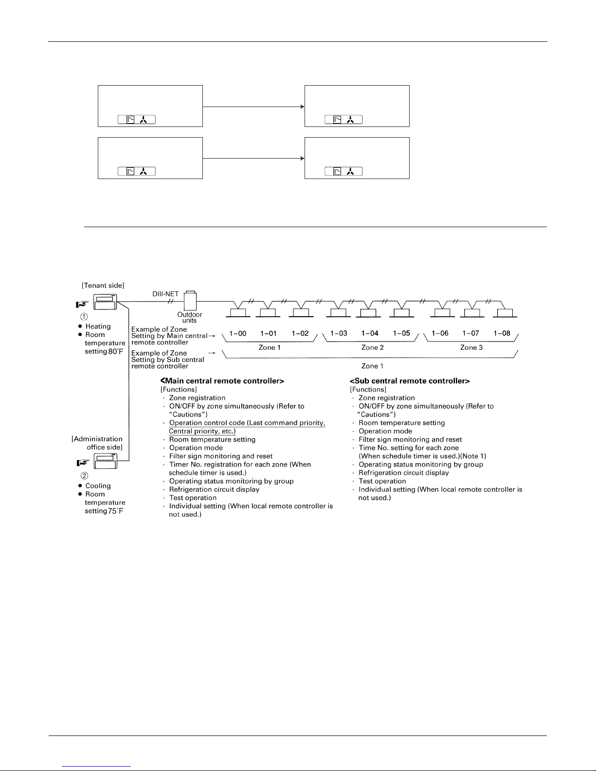
Control with Two Central Remote Controllers
The central remote control equipment is newly designed to "B" type, which has been added with a new control function
for 2 central remote controllers. However, be sure that the relation between Main/Sub of the central remote controller is
different from those of local remote controllers.
Note:
Understand that if the timer No. is registered by the sub-central remote controller, it will be overidden by the Main remote
controller setting upon operation. [Timer mode acceptance for local remote controller (mode no. 8,9,18, and 19)]
<Explanation of the above figure>
If you operate the central remote controller in the sequence of N and O, the indoor unit is set for cooling / temperature
setting 75°F.
However, the display of zone setting of the master remote controller remains at heating / temperature setting at 80°F.
<Cautions>
Operation code cannot be set by the sub central remote controller.
Combined zone operation can only be set by zone registration of the main central remote controller.
Both main and sub central remote controller are operated by a last priority command for the functions other than the
above.
However, the display on the central remote controller cannot be changed by each other. (On the display for the group,
you can monitor the present operation status.)
Remote control having the
selection eligibility
Remote controller having
no sign.
( )
Other remote controller
Remote controller having
no sign.
( )
Remote control having the
selection eligibility
Remote controller having
no sign.
( )
Other remote controller
Remote controller having
no sign.
( )
Set to Cooling, Heating
and Auto (only for Heat
Recovery series);
Set to [Fan];
• Changes to the operation mode
selected by the remote controller
having the selection eligibility.
• However, you can still change to
[Fan], or change from [cooling] to
[dry].
• Can only be set to [Fan].
EDUS391000-C Control Devices
Controls 25
Sequential Start
<Operation command from central control equipment>
Each unit operates in sequence. For example, if you set the simultaneous operation by the central remote controller,
which controls 1-00 ~ 4-15 and 5-00 ~ 8-15 groups, two outdoor units start simultaneously.
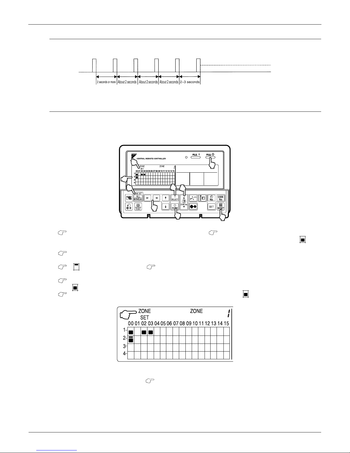
Registering Zone
It is possible to set multiple groups as one zone and control each zone separately.
No zones are registered when the unit is shipped from the factory.
Zone registration can be done in the individual screen, all screen, or zone screen.
Registration
1. Pressing the "ALL/INDIVIDUAL" button for four seconds. Displays ZONE SET.
Zone Number 1 will be displayed, and if there are any groups already registered in the displayed zone, a “ ” will
light up on the operation monitor.
2. Select the Zone Number to be registered using the "ZONE NUMBER" button.
Keeping the button pressed down will move it rapidly.
3. " "to the group you wish to register using the arrow keys.
Keeping the button pressed down will move it rapidly.
4. Press the "SELECT" button to register that group to the zone.
The " " display lights up on all the selected units.
Pressing the "RESET" button removes the group from that zone, and " " goes off.
Repeat steps 3 and 4 until all the units you wish to register to the zone have been added.
In this example, a screen is shown with units 1-00, 1-02, 1-03, and 2-00 registered to Zone Number 1.
5. Repeat steps 2 to 4 to register to the next zone.
6. Once zone registration is complete, press the "ALL/INDIVIDUAL" button to turn off "ZONE SET" display
and return to the individual screen.
The display returns to the normal screen if nothing is done for one minute when in zone registration mode.
(NOTE)
It is impossible to register one group to several different zones.
If this is done, the last zone registered to will be valid.
7
8
9
4
3
6
1
5
2
1
2
3
5
4
6
7
2
1
Control Devices EDUS391000-C
26 Controls
Batch deletion of zone registration
1. Pressing the "ALL " for at least four seconds while pressing the "FILTER SIGN RESET" button
when "ZONE SET" is displayed will delete all zone registrations.
The zone registrations for all units will be lost.
Zone setting
Set the screen of [Zone 0] on the display, and if you set the following mode, you can set to all the registered zone on the
central remote controller by one operation.
Operation mode
Control mode
Room temperature setting
Time No.
Display of "NOT AVAILABLE"
If indoor units are not available for functions subject to control even when attempting to operate these functions from
DCS302C71, the system will display this "NOT AVAILABLE" message.
This message is displayed for a period of approximately two seconds. However, if any button corresponding to functions
not available while the "NOT AVAILABLE" is displayed, it will be displayed for a period of another approximately two
seconds.
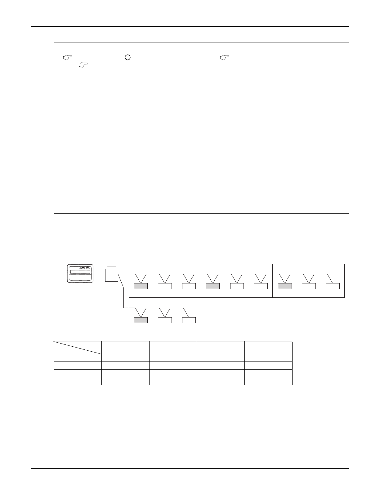
Monitor in zone unit
Operating and monitoring the system even in group or zone unit has become enabled from the DCS302C71.
Monitoring in zone unit is conducted taking an indoor unit with a lower address within the zone as the Main Indoor Unit.
For monitoring the zone settings:The following screens are displayed.
If the system is operated on the Zone screen, one and the same setting will be made on all indoor units registered with
the zone.
On the Zone screen, ventilation mode is only monitored. In order to change ventilation mode, be sure to use the
Individual screen.
On the Batch screen, operating and monitoring is also enabled, thus monitoring an indoor unit with a lower address
within the scope of control.
Main Indoor Unit
Operation Code
Timer No.
Temp. Display Operation Mode
Zone 1 1-00 1-00 1-00 1-00
Zone 2 1-03 1-03 1-03 1-03
Zone 3 1-06 1-06 1-07 1-07
Zone 4 2-00 2-00 N/A N/A
9
8
2
1-00 1-01 1-02
Zone 1
1-03 1-04 1-05
Zone 2
1-06 1-07 1-08
Zone 3
2-00 3-00 4-00
Zone 4
Central Remote
Controller
Outdoor Unit
Indoor Unit
 Loading...