

Daikin FXAQ-MAVE Technical Data Manual
technical data
Wall Mounted Unit
FXAQ-MAVE
air conditioning systems
EEDDE08-204
2e
•VRV® Systems • Indoor Units
1
• Indoor Units • WALL MOUNTED UNIT • FXAQ-MAVE
TABLE OF CONTENTS
FXAQ-MAVE
1 Specifications . . . . . . . . . . . . . . . . . . . . . . . . . . . . . . . . . . . . . . . . . . . . . . . . . . . . . . . 2
Technical Specifications . . . . . . . . . . . . . . . . . . . . . . . . . . . . . . . . . . . . . . . . . . . . . 2
Electrical Specifications . . . . . . . . . . . . . . . . . . . . . . . . . . . . . . . . . . . . . . . . . . . . . 3
2 Safety device settings . . . . . . . . . . . . . . . . . . . . . . . . . . . . . . . . . . . . . . . . . . . . . 4
3Options . . . . . . . . . . . . . . . . . . . . . . . . . . . . . . . . . . . . . . . . . . . . . . . . . . . . . . . . . . . . . . 4
4 Control systems . . . . . . . . . . . . . . . . . . . . . . . . . . . . . . . . . . . . . . . . . . . . . . . . . . . . 5
5 Capacity tables . . . . . . . . . . . . . . . . . . . . . . . . . . . . . . . . . . . . . . . . . . . . . . . . . . . . . 6
Cooling capacity tables . . . . . . . . . . . . . . . . . . . . . . . . . . . . . . . . . . . . . . . . . . . . . . 6
Heating capacity tables . . . . . . . . . . . . . . . . . . . . . . . . . . . . . . . . . . . . . . . . . . . . . . 8
6 Dimensional drawing & centre of gravity . . . . . . . . . . . . . . . . . . . . . . . 10
Dimensional drawing . . . . . . . . . . . . . . . . . . . . . . . . . . . . . . . . . . . . . . . . . . . . . . . . 10
7 Piping diagram. . . . . . . . . . . . . . . . . . . . . . . . . . . . . . . . . . . . . . . . . . . . . . . . . . . . . 12
8 Wiring diagram. . . . . . . . . . . . . . . . . . . . . . . . . . . . . . . . . . . . . . . . . . . . . . . . . . . . . 13
Wiring diagram . . . . . . . . . . . . . . . . . . . . . . . . . . . . . . . . . . . . . . . . . . . . . . . . . . . . . . 13
9 Sound data . . . . . . . . . . . . . . . . . . . . . . . . . . . . . . . . . . . . . . . . . . . . . . . . . . . . . . . . . 14
Sound pressure spectrum . . . . . . . . . . . . . . . . . . . . . . . . . . . . . . . . . . . . . . . . . . . 14
10 Installation . . . . . . . . . . . . . . . . . . . . . . . . . . . . . . . . . . . . . . . . . . . . . . . . . . . . . . . . . . 16
Service space . . . . . . . . . . . . . . . . . . . . . . . . . . . . . . . . . . . . . . . . . . . . . . . . . . . . . . . 16
• Indoor Units • WALL MOUNTED UNIT • FXAQ-MAVE
•VRV® Systems • Indoor Units
2
1 Specifications
Indoor Unit VRV Systems FXAQ-MAVE Wall Mounte
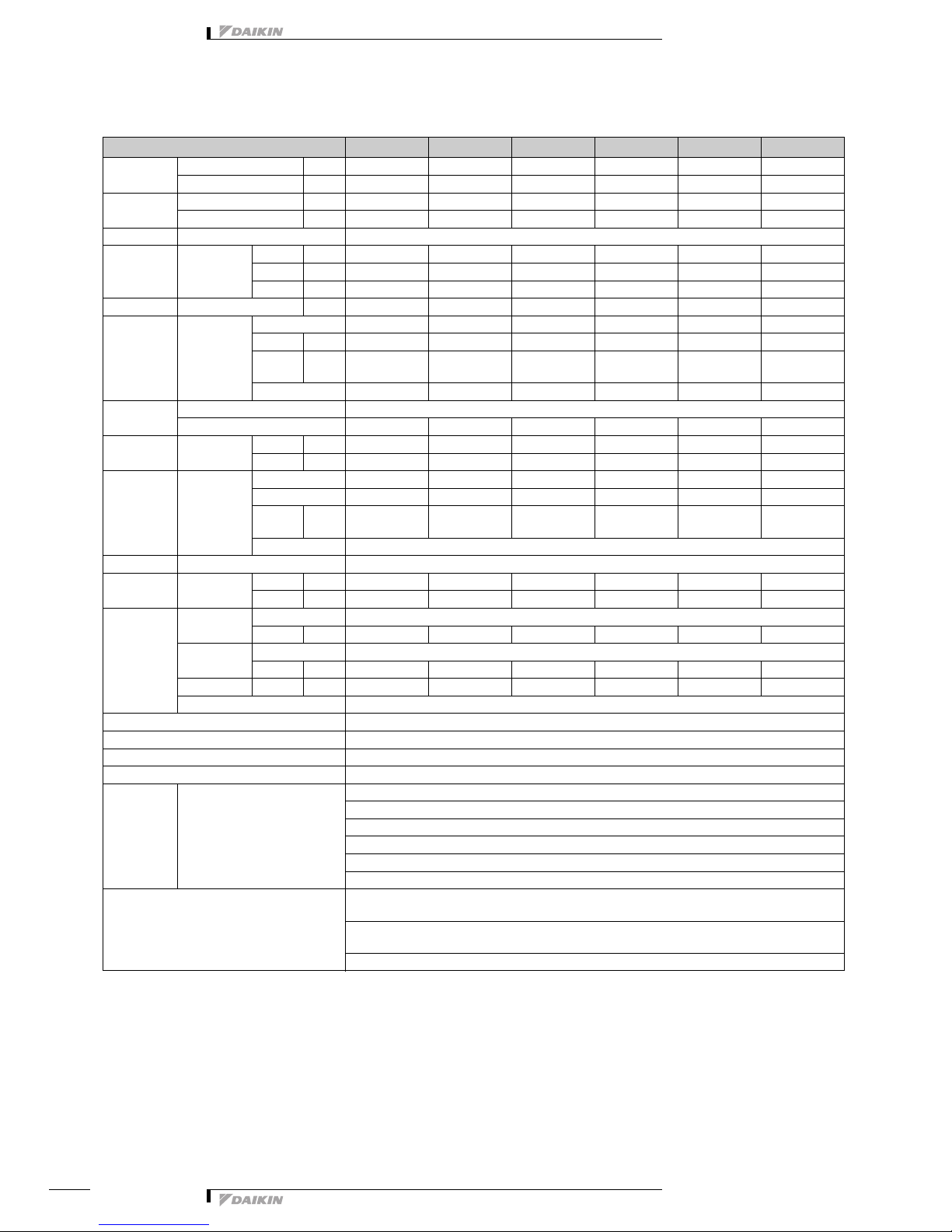
1-1 TECHNICAL SPECIFICATIONS FXAQ20MAVE FXAQ25MAVE FXAQ32MAVE FXAQ40MAVE FXAQ50MAVE FXAQ63MAVE
Nominal
Capacity
Cooling kW 2.20 2.80 3.60 4.50 5.60 7.10
Heating kW 2.50 3.20 4.00 5.00 6.30 8.00
Power input
(Nominal)
Cooling kW 0.016 0.022 0.027 0.020 0.027 0.050
Heating kW 0.024 0.027 0.032 0.020 0.032 0.060
Casing Colour white (3.0Y8.5/0.5)
Dimensions Unit Height mm 290 290 290 290 290 290
Width mm 795 795 795 1050 1050 1050
Depth mm 230 230 230 230 230 230
Weight Unit kg 11 11 11 14 14 14
Heat
Exchanger
DimensionsNr of Rows 222222
Fin Pitch mm 1.40 1.40 1.40 1.40 1.40 1.40
Face
Area
m² 0.161 0.161 0.161 0.213 0.213 0.213
Nr of Stages 14 14 14 14 14 14
Fan Type Cross flow fan
Quantity 1111
Air Flow Rate Cooling High m³/min 7.50 8.00 9.00 12.00 15.00 19.00
Low m³/min 4.50 5.00 5.50 9.00 12.00 14.00
Fan Motor Quantity 1 1 1111
Model QCL9661M QCL9661M QCL9661M QCL9686M QCL9686M QCL9686M
Output
(high)
W404040434343
Drive Direct drive
Refrigerant Name R-410A
Cooling Sound
Pressure
High dBA 35.0 36.0 37.0 39.0 42.0 46.0
Low dBA 29.0 29.0 29.0 34.0 36.0 39.0
Piping
connections
Liquid (OD) Type Flare connection
Diameter mm 6.4 6.4 6.4 6.4 6.35 9.5
Gas Type Flare connection
Diameter mm 12.7 12.7 12.7 12.7 12.7 15.9
DrainDiametermm181818181818
Heat Insulation Foamed polystyrene/polyethylene
Air Filter Washable resin net
Refrigerant control Electronic expansion valve
Temperature control Microprocessor thermostat for cooling and heating
Safety devices PC board fuse
Standard
Accessories
Standard Accessories Installation and operation manual
Installation panel
Paper pattern for installation
Insulation tape
Clamps
Screws
Notes Nominal cooling capacities are based on : indoor temperature : 27°CDB, 19° CWB, outdoor temperature : 35°CDB,
equivalent refrigerant piping : 5m (horizontal)
Nominal heating capacities are based on : indoor temperature : 20°CDB, outdoor temperature : 7°CDB, 6° CWB,
equivalent refrigerant piping : 5m (horizontal)
Capacities are net, including a deduction for cooling (an addition for heating) for indoor fan motor heat.

•VRV® Systems • Indoor Units
3
• Indoor Units • WALL MOUNTED UNIT • FXAQ-MAVE
1 Specifications
21
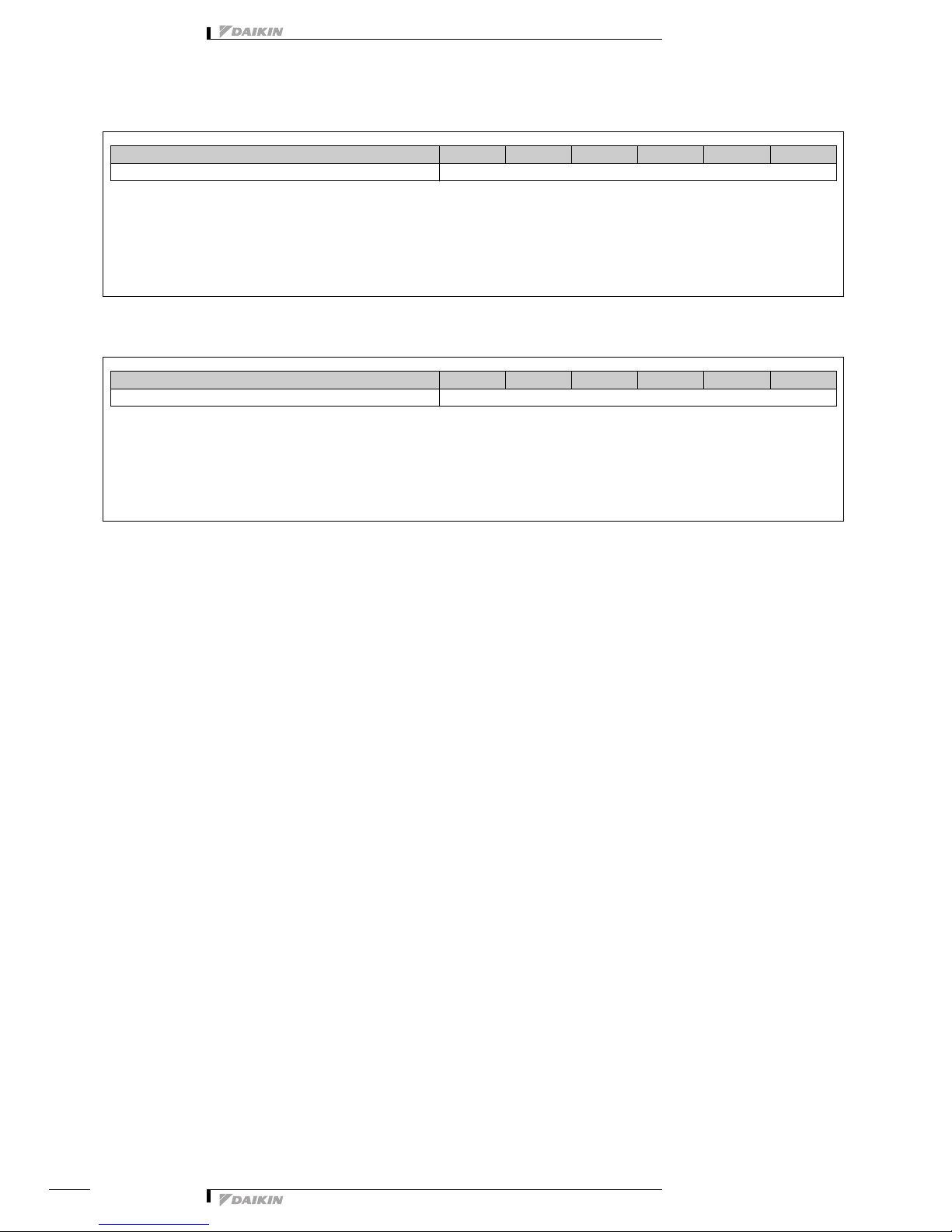
1-2 ELECTRICAL SPECIFICATIONS FXAQ20MAVE FXAQ25MAVE FXAQ32MAVE FXAQ40MAVE FXAQ50MAVE FXAQ6 3MAVE
Power Supply Name VE
Phase 111111
Frequency Hz 50 50 50 50 50 50
Voltage V 220-240
Current Minimum circuit amps
(MCA)
A 0.30 0.40 0.40 0.40 0.40 0.60
Maximum fuse amps (MFA) A 15.00 15.00 15.00 15.00 15.00 15.00
Full load amps (FLA) A 0.20 0.30 0.30 0.30 0.30 0.50
Voltage range Minimum V -10%
Maximum V +10%
Notes Voltage range : units are suitable for use on electrical systems where voltage supplied to unit terminals is not below
or above listed range limits.
Maximum allowable voltage range variation between phases is 2%.
MCA/MFA : MCA = 1.25 x FLA
MFA<= 4 x FLA
next lower standard fuse rating minimum 15A
select wire size based on the MCA
instead of a fuse, use a circuit breaker
For more details concerning conditional connections, see http://extranet.daikineurope.com, select "E-Data Books”.
Finally, click on the document title of your choice.
• Indoor Units • WALL MOUNTED UNIT • FXAQ-MAVE
•VRV® Systems • Indoor Units
4
2 Safety device settings
3 Options
FXAQ20MA FXAQ25MA FXAQ32MA FXAQ40MA FXAQ50MA FXAQ63MA
PC BOARD FUSE 250V 3A
4D034906F
FXAQ20MA FXAQ25MA FXAQ32MA FXAQ40MA FXAQ50MA FXAQ63MA
DRAIN PUMP KIT K-KDU572CVE
ED39-226B
•VRV® Systems • Indoor Units
5
• Indoor Units • WALL MOUNTED UNIT • FXAQ-MAVE
4 Control systems
Individual control systems
Centralised control systems
Others
PCV0320
NOTES
1 Installation box is necessary for each adapter marked with #.
2 Up to 2 adapters can be fixed per installation box.
3 Only 1 installation box can be installed per indoor unit.
FXAQ20MA FXAQ25MA FXAQ32MA FXAQ40MA FXAQ50MA FXAQ63MA
WIRED REMOTE CONTROL BRC1D52
INFRARED REMOTE CONTROL Heat pump BRC7E618
Cooling only BRC7E619
FXAQ20MA FXAQ25MA FXAQ32MA FXAQ40MA FXAQ50MA FXAQ63MA
CENTRALISED REMOTE CONTROL DCS302C51
UNIFIED ON/OFF CONTROL DCS301B51
SCHEDULE TIMER DST301B51
FXAQ20MA FXAQ25MA FXAQ32MA FXAQ40MA FXAQ50MA FXAQ63MA
WIRING ADAPTER FOR ELECTRICAL APPENDICES (1) KRP2A51#
WIRING ADAPTER FOR ELECTRICAL APPENDICES (2) KRP4A51#
INSTALLATION BOX FOR ADAPTER PCB (2) (3) KRP4A93
REMOTE SENSOR KRCS01-1
ELECTRICAL BOX WITH EARTH TERMINAL (3 BLOCKS) KJB311A
ELECTRICAL BOX WITH EARTH TERMINAL (2 BLOCKS) KJB212A
NOISE FILTER (FOR ELECTROMAGNETIC INTERFACE USE ONLY)
KEK26-1A
EXTERNAL CONTROL ADAPTER FOR OUTDOOR UNITS (INSTALLATION ON INDOOR UNIT) DTA104A61#
 Loading...