

Daikin FXAQ20PVE, FXAQ25PVE, FXAQ32PVE, FXAQ40PVE, FXAQ50PVE Installation manuals
...
INSTALLATION MANUAL
SYSTEM Air Conditioners
English
Français
MODELS
Wall-mounted type
FXAQ20PVE
FXAQ25PVE
FXAQ32PVE
FXAQ40PVE
FXAQ50PVE
FXAQ63PVE
CAREFULLY READ THESE INSTRUCTIONS BEFORE INSTALLATION.
KEEP THIS MANUAL IN A HANDY PLACE FOR FUTURE REFERENCE.
VEUILLEZ LIRE ATTENTIVEMENT CES INSTRUCTIONS AVANT L'INSTALLATION.
CONSERVEZ CE MANUEL EN LIEU SÛR POUR POUVOIR VOUS Y REPORTER
ULTÉRIEUREMENT.
LEA DETENIDAMENTE ESTAS INSTRUCCIONES ANTES DE LA INSTALACIÓN.
CONSERVE ESTE MANUAL PARA POSIBLES CONSULTAS FUTURAS.
PRIMA DELL'INSTALLAZIONE, LEGGERE ATTENTAMENTE LE PRESENTI ISTRUZIONI.
CONSERVARE IL PRESENTE MANUALE IN UN LUOGO FACILMENTE ACCESSIBILE PER
RIFERIMENTO FUTURO.
LEES DEZE INSTRUCTIES ZOGVULDIG DOOR VOORDAT MET DE INSTALLATIE WORDT
BEGONNEN.
BEWAAR DEZE HANDLEIDING VOOR TOEKOMSTIG GEBRUIK OP EEN GESCHIKTE
PLAATS ONDER HANDBEREIK.
LEIA ATENTAMENTE ESTAS INSTRUÇÕES ANTES DA INSTALAÇÃO.
MANTENHA ESTE MANUAL NUM LOCAL DE FÁCIL ACESSO PARA CONSULTA.
Español
Italiano
Nederlands
Português
FXAQ20PVE
FXAQ25PVE
FXAQ32PVE
FXAQ40PVE
FXAQ50PVE
FXAQ63PVE
VRV SYSTEM
Air Conditioners
Installation manual
CONTENTS
1. SAFETY PRECAUTIONS...............................................................................................1
2. BEFORE INSTALLATION ..............................................................................................3
3. SELECTING INSTALLATION SITE................................................................................5
4. INDOOR UNIT INSTALLATION .....................................................................................6
5. REFRIGERANT PIPING WORK ....................................................................................9
6. DRAIN PIPING WORK.................................................................................................12
7. ELECTRIC WIRING WORK .........................................................................................13
8. HOW TO CONNECT WIRINGS AND WIRING EXAMPLE ..........................................14
9. FIELD SETTINGS ........................................................................................................20
10. TEST RUN....................................................................................................................21
The original instructions are written in English. All other languages are translations of the original instructions.
1. SAFETY PRECAUTIONS
Be sure to follow this “SAFETY PRECAUTIONS”.
This product comes under the term “appliances not accessible to the general public”.
This is a class A product. In a domestic environment this product may cause radio interference in which case
the user may be required to take adequate measures.
This manual classifies the precautions into WARNINGS and CAUTIONS.
Be sure to follow all the precautions below: They are all important for ensuring safety.
WARNING .........Indicates a potentially hazardous situation which, if not avoided, could result in death
or serious injury.
CAUTION ..........Indicates a potentially hazardous situation which, if not avoided, may result in minor
or moderate injury.
It may also be used to alert against unsafe practices.
• After the installation is completed, test the air conditioner and check if the air conditioner operates properly.
Give the user adequate instructions concerning the use and cleaning of the indoor unit according to the
Operation Manual. Ask the user to keep this manual and the Operation Manual together in a handy place
for future reference.
WARNING
• Ask your local dealer or qualified personnel to carry out installation work.
Improper installation may result in water leakage, electric shocks or a fire.
• Perform installation work in accordance with this installation manual.
Improper installation may result in water leakage, electric shocks or a fire.
• Consult your local dealer regarding what to do in case of refrigerant leakage.
When the air conditioner is installed in a small room, it is necessary to take proper measures so that the
amount of any leaked refrigerant does not exceed the concentration limit in the event of a leakage.
Otherwise, this may lead to an accident due to oxygen deficiency.
• Be sure to use only the specified parts and accessories for installation work.
Failure to use the specified parts may result in the air conditioner falling down, water leakage, electric
shocks, a fire, etc.
English 1
• Install the air conditioner on a foundation that can withstand its mass.
Insufficient strength may result in the air conditioner falling down and causing injury.
In addition, it may lead to vibration of indoor units and cause unpleasant chattering noise.
• Carry out the specified installation work in consideration of strong winds, typhoons, or earthquakes.
Improper installation may result in an accident such as air conditioner falling.
• Make certain that all electrical work is carried out by qualified personnel according to the applicable legislation (note 1) and this installation manual, using a separate circuit.
In addition, even if the wiring is short, make sure to use a wiring that has sufficient length and never connect
additional wiring to make the length sufficient.
Insufficient capacity of the power supply circuit or improper electrical construction may lead to electric
shocks or a fire.
(note 1) applicable legislation means “All international, national and local directives, laws, regulations and/
or codes which are relevant and applicable for a certain product or domain”.
• Earth the air conditioner.
Do not connect the earth wiring to gas or water piping, lightning conductor or telephone earth wiring.
Incomplete earthing may cause electric shocks or a fire.
A high surge current from lightning or other sources may cause damage to the air conditioner.
• Be sure to install an earth leakage circuit breaker.
Failure to do so may cause electric shocks and a fire.
• Disconnect the power supply before touching the electric components.
If you touch the live part, you may get an electric shocks.
• Make sure that all wiring is secure, using the specified wiring and ensuring that external forces do not act
on the terminal connections or wiring.
Incomplete connection or fixing may cause an overheat or a fire.
• When wiring between the indoor and outdoor units, and wiring the power supply, form the wiring orderly so
that the control box lid can be securely fastened.
If the control box lid is not in place, overheat of the terminals, electric shocks or a fire may be caused.
• If refrigerant gas leaks during installation work, ventilate the area immediately.
Toxic gas may be produced if refrigerant gas comes into contact with a fire.
• After completing the installation work, check to make sure that there is no leakage of refrigerant gas.
Toxic gas may be produced if refrigerant gas leaks into the room and comes into contact with a source of
a fire, such as a fan heater, stove or cooker.
• Never directly touch any accidental leaking refrigerant. This could result in severe wounds caused by frostbite.
CAUTION
• Install drain piping according to this installation manual to ensure good drainage, and insulate the piping to
prevent condensation.
Improper drain piping may cause water leakage, make the furniture get wet.
• Install the air conditioner, power supply wiring, remote controller wiring and transmission wiring at least
1 meter away from televisions or radios to prevent image interference or noise.
(Depending on the radio waves, a distance of 1 meter may not be sufficient to eliminate the noise.)
• Install the indoor unit as far as possible from fluorescent lamps.
If a wireless remote controller kit is installed, the transmission distance may be shorter in a room where an
electronic lighting type (inverter or rapid start type) fluorescent lamp is installed.
• Do not install the air conditioner in places such as the following:
1. Where there is mist of oil, oil spray or vapour for example a kitchen.
Resin parts may deteriorate, and cause them to fall out or water to leak.
2. Where corrosive gas, such as sulfurous acid gas, is produced.
Corrosion of copper pipings or brazed parts may cause the refrigerant to leak.
3. Where there is machinery which emits electromagnetic waves.
Electromagnetic waves may disturb the control system, and cause malfunction of the equipment.
4. Where flammable gases may leak, where carbon fibre or ignitable dust is suspended in the air or where
volatile flammables, such as thinner or gasoline, are handled.
If the gas should leak and remained around the air conditioner, it may cause ignition.
• The air conditioner is not intended for use in a potentially explosive atmosphere.
2 English
2. BEFORE INSTALLATION
Do not exert pressure on the resin parts when opening the unit or when moving it after opening.
Be sure to check the type of R410A refrigerant to be used before doing any work. (Using an incorrect
refrigerant will prevent normal operation of the unit.)
• When opening the unit or moving it after opening, be sure to lift it by holding on to the lifting lugs without
exerting any pressure on other parts, especially, drain piping, and other resin parts.
• Decide upon a line of transport.
• Leave the unit inside its packaging while moving, until reaching the installation site. Use a sling of soft mate-
rial, where unpacking is unavoidable or protective plates together with a rope when lifting, to avoid damage
or scratches to the unit.
• Especially, do not unfasten packing case (top) guarding the control box until suspending the unit.
• Refer to the installation manual of the outdoor unit for items not described in this manual.
• Do not dispose of any parts necessary for installation until the installation is complete.
2-1 PRECAUTIONS
• Be sure to read this manual before installing the indoor unit.
• When selecting installation site, refer to the installation pattern.
• This unit, both indoor and outdoor, is suitable for installation in a commercial and light industrial
environment. If installed as a household appliance it could cause electromagnetic interference.
• Entrust installation to the place of purchase or a qualified serviceman. Improper installation could lead to
leaks and, in worse cases, electric shock of fire.
• Use only parts provided with the unit or parts satisfying required specifications. Unspecified parts could
cause the unit to fall out of place, or could lead to leaks and, in worse cases, electric shock or fire.
• Do not install or operate the unit in rooms mentioned below.
• Laden with mineral oil, or filled with oil vapor or spray like in kitchens. (Plastic parts may
deteriorate which could eventually cause the unit to fall out of place, or could lead to leaks.)
• Where corrosive gas like sulfurous gas exists. (Copper tubing and brazed spots may corrode,
which could eventually lead to refrigerant leaks.)
• Where volatile flammable gas like thinner or gasoline is used.
• Where exposed to combustible gases and where volatile flammable gas like thinner or gasoline
is used. (Gas in the vicinity of the unit could ignite.)
• Where machines can generate electromagnetic waves. (Control system may malfunction.)
• Where the air contains high levels of salt such as that near the ocean and where voltage
fluctuates greatly such as that in factories. Also in vehicles or vessels.
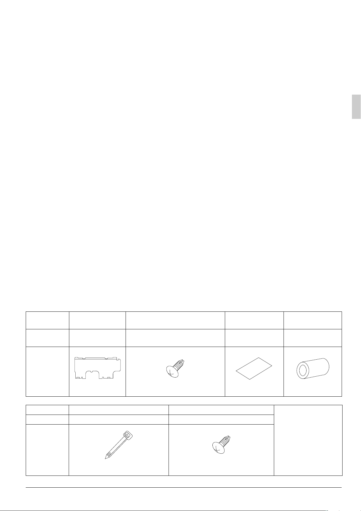
2-2 ACCESSORIES
Check the following accessories are included with your unit.
Name
Quantity 1 set
Shape
Name (5) Clamp (6) Securing screws
Quantity 1 large 3 small 2 pcs.
Shape
(1) Installation
panel
(2) Attachment screws
for the installation panel
8 pcs. → FXAQ20,25,32 type
9 pcs. → FXAQ40,50,63 type
M4 × 25L
(3) Paper pattern
for installation
1 pc. 1 pc.
(Other)
• Operation manual
• Installation manual
(4) Insulating tape
M4 × 12L
English 3

2-3 OPTIONAL ACCESSORIES
• These are two types of remote controllers: wired and wireless. Select a remote controller according to
customer request and install in an appropriate place.
Remote controller type Model
Wired type BRC1C62 · *BRC1D61 · *BRC1E61
Wireless type
* Refer to an installation manual attached to the remote controller.
NOTE
• If the customer wishes to use a remote controller that is not listed above, select a suitable remote
controller after consulting catalogs and technical materials.
Heat pump type BRC7E618
Cooling only type BRC7E619
FOR THE FOLLOWING ITEMS, TAKE SPECIAL CARE DURING CONSTRUCTION AND
CHECK AFTER INSTALLATION IS FINISHED.
a. Items to be checked after completion of work
Items to be checked If not properly done, what is likely to occur Check
Are the indoor and outdoor unit fixed
firmly?
Is the outdoor unit fully installed?
Is the gas leak test finished? It may result in insufficient cooling.
Is the unit fully insulated? Condensate water may drip.
Does drainage flow smoothly? Condensate water may drip.
Does the power supply voltage correspond
to that shown on the name plate?
Are wiring and piping correct?
Is the unit safely earthed? Dangerous at electric leakage.
Is wiring size according to specifications?
Is something blocking the air outlet or inlet
of either the indoor or outdoor units?
Are refrigerant piping length and additional
refrigerant charge noted down?
The units may drop, vibrate or make noise.
The unit may malfunction or the components burn out.
The unit may malfunction or the components burn out.
The unit may malfunction or the components burn out.
The unit may malfunction or the components burn out.
It may result in insufficient cooling.
The refrigerant charge in the system is not
clear.
b. Items to be checked at time of delivery
Also review the “SAFETY PRECAUTIONS”
Items to be checked Check
Are the control box cover, air filter, suction grille attached?
Did you explain about operations while showing the instruction manual to your customer?
Did you hand the instruction manual over to your customer?
c. Points for explanation about operations
The items with WARNING and CAUTION marks in the instruction manual are the items pertaining
to possibilities for bodily injury and material damage in addition to the general usage of the product.
Accordingly, it is necessary that you make a full explanation about the described contents and also ask
your customers to read the instruction manual.
4 English
2-4 NOTE TO THE INSTALLER
Be sure to instruct customers how to properly operate the unit (especially cleaning filters, operating different
functions, and adjusting the temperature) by having them carry out operations themselves while looking at the
manual.
3. SELECTING INSTALLATION SITE
(1) Select an installation site where the following conditions are fulfilled and that meets with your
customer’s approval.
• In the upper space (including the back of the ceiling) of the indoor unit where there is no possible
dripping of water from the refrigerant pipe, drain pipe, water pipe, etc.
• Where the wall is strong enough to bear the indoor unit weight.
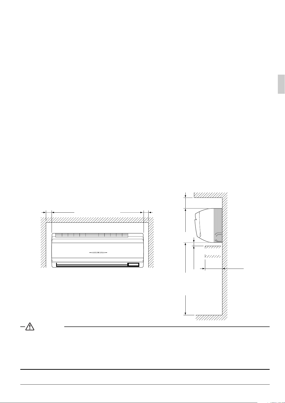
• Where sufficient clearance for installation and maintenance can be ensured.
(Refer to Fig. 1 and Fig. 2)
• Where optimum air distribution can be ensured.
• Where nothing blocks the air passage.
• Where condensate can be properly drained.
• Where the wall is not significantly tilted.
• Where not exposed to combustible gases.
• Where pipe between indoor and outdoor units is possible within the allowable limit.
(Refer to the installation manual of the outdoor unit.)
• Install the indoor and outdoor units, power cable and transmission wiring, at least 1 m from TVs and
radios, to prevent distorted pictures and static. (Depending on the type and source of the electrical
waves, static may be heard even when more than 1 m away.)
• Install the indoor unit no less than 2.5 m above the floor. Where unavoidably lower, take what measures
are necessary to keep hands out of the air inlet.
• Where the cool (warm) air reaches all across the room.
[ Space required for installation (mm) ]
≥ 50 ≥ 50
≥ 90
Obstruction
≥ 30
Fig. 1
CAUTION
• The indoor and outdoor units and the power supply wiring and remote controller cord must be installed at
least 1m away from any televisions or radios. This is to prevent interference with picture and sound reception. (Interference may occur even at 1m away depending on the reception quality.)
• If installing the wireless kit, the distance of the signal sent from the remote controller might be shorter if
there are fluorescent lights which are electrically started (such as with inverters, rapid starters, etc.) in the
room. The indoor unit should be installed as far away from fluorescent lights as possible.
≥ 2500 (from floor)
For installation
in high places.
Floor
≤ 120
Fig. 2
English 5
(2) Consider whether the place where the unit will be installed can support the full weight of the unit,
and reinforce it with boards and beams, etc. if needed before proceeding with the installation.
Also, reinforce the place to prevent vibration and noise before installing.
(The installation pitch can be found on the paper pattern for installation (3), so refer to it when considering the necessity for reinforcing the location.)
(3) The indoor unit may not be directly installed on the wall. Use the attached installation panel (1)
before installing the unit.
4. INDOOR UNIT INSTALLATION
• Use only accessories and parts which are of the designated specification when installing.
CAUTION
• Install so that the unit does not tilt to either side or forward.
• Do not hold the unit by the horizontal flaps when lifting it. (This may damage the horizontal flaps.)
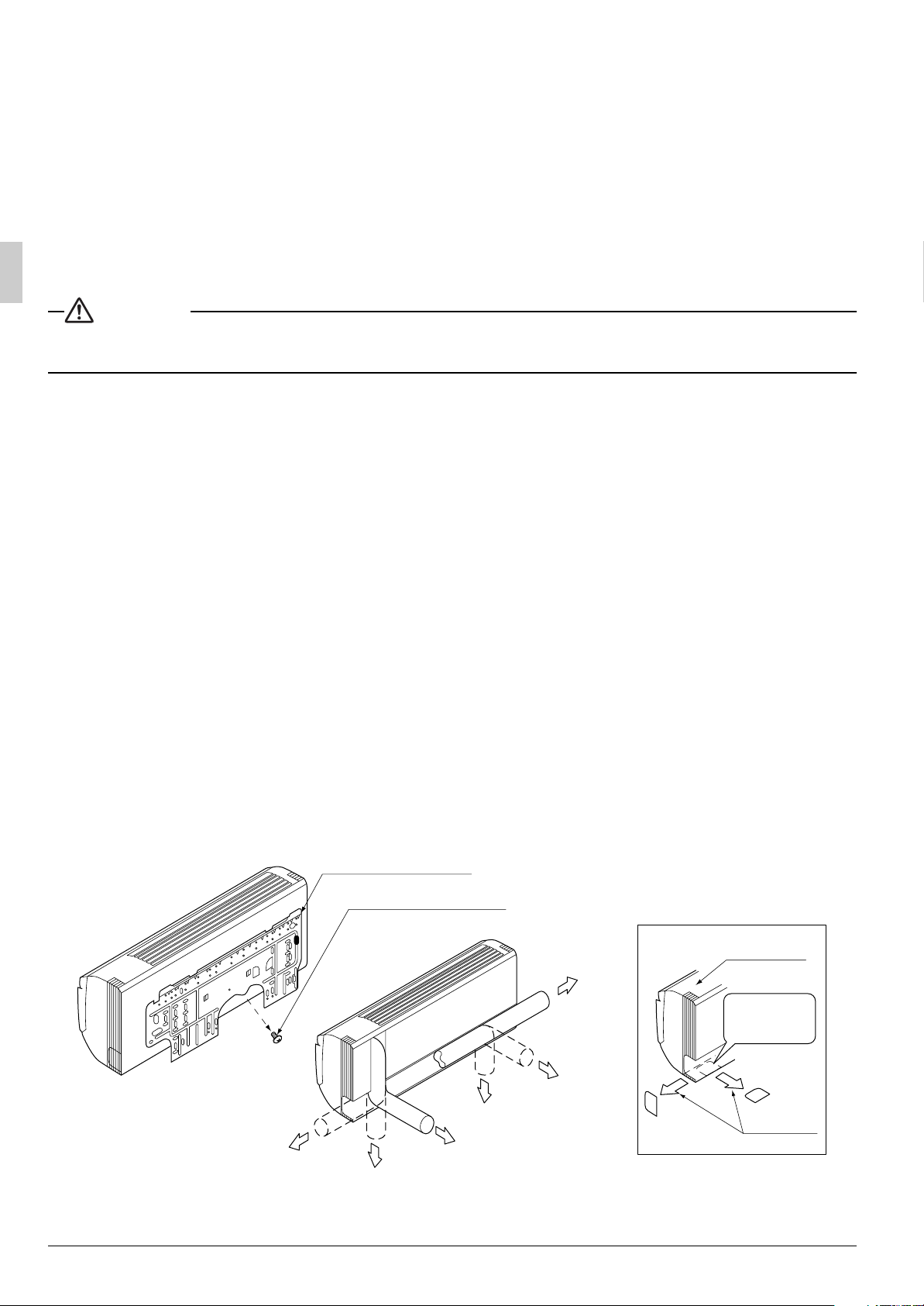
(1) Open the piping through-hole.
• The refrigerant pipe and drain pipe can be passed out in one of 6 directions: left, bottom-left, back-left,
right, bottom-right, and back-right. (Refer to Fig. 3)
• Using the paper pattern for installation (3), choose where to pass the piping out and open a through-hole
(φ80) in the wall.
Open the hole so that there is a downward slope for the drain piping. (See “ 6.DRAIN PIPING WORK ”)
(2) Remove the installation panel (1) from the unit and attach to the wall.
(The installation panel is temporarily attached to the unit with screw. (In case of 20-32 type))
(Refer to Fig. 3)
(a) Check the location for the hole using the included paper pattern for installation (3).
• Choose a location so that there is at least a 90 mm gap between the ceiling and the main unit.
(b) Temporarily attach the installation panel (1) at the temporary-securing position on the paper pattern for
installation (3) and use a level to make sure the drain hose is either level or tilted slightly downward.
(c) Secure the installation panel (1) to the wall using either screws or bolts.
• If using the attachment screws for the installation panel (2), attach using at least 4 screws on either
side (for a total of 8 screws (20-32 type), 9 screws (40-63 type)) of the recommended installation
cleat position on the included paper pattern for installation (3).
• If using bolts, attach using a M8 - M10 bolt (for a total of 2 bolts) on either side.
• If dealing with concrete, use commercially available foundation bolts (M8 - M10).
(3) If using the left, bottom-left, right, or bottom-right positions for the piping, cut out the through-hole
for the piping in the front grille. (Refer to Fig. 4)
Installation panel (1)
Temporary screw
(In case of 20-32 type)
Front grille
Left pipe
Cut out along
the groove.
Back-left pipe
Bottom-left pipe
Back-right pipe
Fig. 3
6 English
Right pipe
Bottom-right pipe
Cut away
Fig. 4
 Loading...