

Page 1
FWP-C
Installation, use and maintenance manual
Medium static pressure ducted fan coil units with EC motors 2 - 8 kW
Manuale installazione, uso e manutenzione
Unità canalizzabili a media prevalenza con motore EC 2 - 8 kW
Manuel d'installation, utilisation et entretien
Unités gainables à pression statique disponible moyenne avec moteur EC 2 - 8 kW
Installations-, Bedienungs- und Wartungsanleitung
Kanalisierbare Einheiten mit mittlerer Förderhöhe mit Motor EC 2 - 8 kW
EN
IT
FR
DE
Manual de instalación, uso y mantenimiento
Unidades canalizables de media presión con motor EC 2 - 8 kW
ES
UT66002770-02 04/21
Page 2
deklaruje na własną i wyłączną odpowiedzialność, że modele klimatyzatorów, których dotyczy niniejsza deklaracja:
Enfocus Software - Customer Support
declară pe proprie răspundere că aparatele de aer condiţionat la care se referă această declaraţie:
z vso odgovornostjo izjavlja, da so modeli klimatskih naprav, na katere se izjava nanaša:
kinnitab oma täielikul vastutusel, et käesoleva deklaratsiooni alla kuuluvad kliimaseadmete mudelid:
декларира на своя отговорност, че моделите климатична инсталация, за които се отнася тази декларация:
visiška savo atsakomybe skelbia, kad oro kondicionavimo prietaisų modeliai, kuriems yra taikoma ši deklaracija:
ar pilnu atbildību apliecina, ka tālāk uzskaitīto modeļu gaisa kondicionētāji, uz kuriem attiecas šī deklarācija:
vyhlasuje na vlastnú zodpovednosť, že tieto klimatizačné modely, na ktoré sa vzťahuje toto vyhlásenie:
tamamen kendi sorumluluǧunda olmak üzere bu bildirinin ilgili olduǧu klima modellerinin aşaǧıdaki gibi olduǧunu beyan eder:
17
18
19
20
21
22
23
24
25
megfelelnek az alábbi szabvány(ok)nak vagy egyéb irányadó dokumentum(ok)nak, ha azokat előírás szerint használják:
spełniają wymogi następujących norm i innych dokumentów normalizacyjnych, pod warunkiem że używane są zgodnie z naszymi instrukcjami:
161718192021222324
Directivelor, cu amendamentele respective.
Direktive z vsemi spremembami.
Direktiivid koos muudatustega.
Директиви, с техните изменения.
Direktyvose su papildymais.
Direktīvās un to papildinājumos.
18192021222324
Direktiver, med senere ændringer.
10111213141516
sunt în conformitate cu următorul (următoarele) standard(e) sau alt(e) document(e) normativ(e), cu condiţia ca acestea să fie utilizate în conformitate cu
instrucţiunile noastre:
skladni z naslednjimi standardi in drugimi normativi, pod pogojem, da se uporabljajo v skladu z našimi navodili:
on vastavuses järgmis(t)e standardi(te)ga või teiste normatiivsete dokumentidega, kui neid kasutatakse vastavalt meie juhenditele:
съответстват на следните стандарти или други нормативни документи, при условие, че се използват съгласно нашите инструкции:
atitinka žemiau nurodytus standartus ir (arba) kitus norminius dokumentus su sąlyga, kad yra naudojami pagal mūsų nurodymus:
tad, ja lietoti atbilstoši ražotāja norādījumiem, atbilst sekojošiem standartiem un citiem normatīviem dokumentiem:
sú v zhode s nasledovnou(ými) normou(ami) alebo iným(i) normatívnym(i) dokumentom(ami), za predpokladu, že sa používajú v súlade snašim
návodom:
ürünün, talimatlarımıza göre kullanılması koşuluyla aşağıdaki standartlar ve norm belirten belgelerle uyumludur:
25
Directives, as amended.
010203040506070809
Smernice, v platnom znení.
Direktiv, med företagna ändringar.
Direktiver, med foretatte endringer.
Direktiivejä, sellaisina kuin ne ovat muutettuina.
v platném znění.
Smjernice, kako je izmijenjeno.
irányelv(ek) és módosításaik rendelkezéseit.
Direktiven, gemäß Änderung.
Directives, telles que modifiées.
Richtlijnen, zoals geamendeerd.
Directivas, según lo enmendado.
Direttive, come da modifica.
Οδηγιών, όπως έχουν τροποποιηθεί.
**
Değiştirilmiş halleriyle Yönetmelikler.
25
———
<A>
<B>
<C>
z późniejszymi poprawkami.
17
както е изложено в <A> и оценено положително от <B>
съгласно Сертификата<C>.
kaip nustatyta <A> ir kaip teigiamai nuspręsta <B> pagal
Sertifikatą<C>.
kā norādīts <A> un atbilstoši <B> pozitīvajam vērtējumam
saskaņā ar sertifikātu<C>.
ako bolo uvedené v <A> a pozitívne zistené <B> vsúlade
s osvedčením<C>.
<A>’da belirtildiği gibi ve <C>Sertifikasına göre <B>
tarafından olumlu olarak değerlendirildiği gibi.
Directivas, conforme alteração em.
Директив со всеми поправками.
21Забележка*
22Pastaba*
23Piezīmes*
24Poznámka*
25Not*
a(z) <A> alapján, a(z) <B> igazolta a megfelelést, a(z)
<C>tanúsítvány szerint.
zgodnie z dokumentacją <A>, pozytywną
opinią <B> i Świadectwem<C>.
aşa cum este stabilit în <A> şi apreciat pozitiv de<B>
în conformitate cu Certificatul<C>.
kot je določeno v <A> in odobreno s strani <B>
vskladu scertifikatom<C>.
nagu on näidatud dokumendis <A> ja heaks kiidetud
<B> järgi vastavalt sertifikaadile<C>.
16Megjegyzés*
17Uwaga*
18Notă*
19Opomba*
20Märkus*
Daikin Europe N.V. je pooblaščen za sestavo datoteke s tehnično mapo.
Daikin Europe N.V. on volitatud koostama tehnilist dokumentatsiooni.
Daikin Europe N.V. е оторизирана да състави Акта за техническа конструкция.
Daikin Europe N.V. yra įgaliota sudaryti šį techninės konstrukcijos failą.
Daikin Europe N.V. ir autorizēts sastādīt tehnisko dokumentāciju.
Spoločnosť Daikin Europe N.V. je oprávnená vytvoriť súbor technickej konštrukcie.
Daikin Europe N.V. Teknik Yapı Dosyasını derlemeye yetkilidir.
19**
20**
21**
22**
23**
24**
25**
Daikin Europe N.V. on valtuutettu laatimaan Teknisen asiakirjan.
Společnost Daikin Europe N.V. má oprávnění ke kompilaci souboru technické konstrukce.
Daikin Europe N.V. je ovlašten za izradu Datoteke o tehničkoj konstrukciji.
A Daikin Europe N.V. jogosult a műszaki konstrukciós dokumentáció összeállítására.
Daikin Europe N.V. ma upoważnienie do zbierania i opracowywania dokumentacji konstrukcyjnej.
Daikin Europe N.V. este autorizat să compileze Dosarul tehnic de construcţie.
13**
14**
15**
16**
17**
18**
заявляет, исключительно под свою ответственность, что модели кондиционеров воздуха, к которым относится настоящее заявление:
erklærer under eneansvar, at klimaanlægmodellerne, som denne deklaration vedrører:
deklarerar i egenskap av huvudansvarig, att luftkonditioneringsmodellerna som berörs av denna deklaration innebär att:
erklærer et fullstendig ansvar for at de luftkondisjoneringsmodeller som berøres av denne deklarasjon, innebærer at:
ilmoittaa yksinomaan omalla vastuullaan, että tämän ilmoituksen tarkoittamat ilmastointilaitteiden mallit:
prohlašuje ve své plné odpovědnosti, že modely klimatizace, k nimž se toto prohlášení vztahuje:
izjavljuje pod isključivo vlastitom odgovornošću da su modeli klima uređaja na koje se ova izjava odnosi:
teljes felelőssége tudatában kijelenti, hogy a klímaberendezés modellek, melyekre e nyilatkozat vonatkozik:
09
10
11
12
13
14
15
16
estão em conformidade com a(s) seguinte(s) norma(s) ou outro(s) documento(s) normativo(s), desde que estes sejam utilizados de
acordo com as nossas instruções:
соответствуют следующим стандартам или другим нормативным документам, при условии их использования согласно нашим инструкциям:
overholder følgende standard(er) eller andet/andre retningsgivende dokument(er), forudsat at disse anvendes i henhold til vore instrukser:
respektive utrustning är utförd i överensstämmelse med och följer följande standard(er) eller andra normgivande dokument, under förutsättning att
användning sker i överensstämmelse med våra instruktioner:
respektive utstyr er i overensstemmelse med følgende standard(er) eller andre normgivende dokument(er), under forutssetning av at disse brukes i
henhold til våre instrukser:
vastaavat seuraavien standardien ja muiden ohjeellisten dokumenttien vaatimuksia edellyttäen, että niitä käytetään ohjeidemme mukaisesti:
za předpokladu, že jsou využívány v souladu s našimi pokyny, odpovídají následujícím normám nebo normativním dokumentům:
08091011121314
u skladu sa slijedećim standardom(ima) ili drugim normativnim dokumentom(ima), uz uvjet da se oni koriste u skladu s našim uputama:
15
Machinery 2006/42/EC
Low Voltage 2014/35/EU
enligt <A> och godkänts av <B> enligt
Certifikatet<C>.
som det fremkommer i <A> og gjennom positiv
bedømmelse av <B> ifølge Sertifikat<C>.
jotka on esitetty asiakirjassa <A> ja jotka <B>
Electromagnetic Compatibility 2014/30/EU
ob upoštevanju določb:
vastavalt nõuetele:
следвайки клаузите на:
laikantis nuostatų, pateikiamų:
ievērojot prasības, kas noteiktas:
održiavajúc ustanovenia:
19202122232425
under iagttagelse af bestemmelserne i:
101112131415161718
bunun koşullarına uygun olarak:
enligt villkoren i:
gitt i henhold til bestemmelsene i:
noudattaen määräyksiä:
za dodržení ustanovení předpisu:
prema odredbama:
követi a(z):
zgodnie z postanowieniami Dyrektyw:
în urma prevederilor:
on hyväksynyt Sertifikaatin<C> mukaisesti.
11Information*
12Merk*
13Huom*
delineato nel <A> e giudicato positivamente da<B>
secondo il Certificato<C>.
όπως καθορίζεται στο <A> και κρίνεται θετικά
από το <B> σύμφωνα με το Πιστοποιητικό<C>.
tal como estabelecido em <A> e com o parecer positivo
de <B> de acordo com o Certificado<C>.
06Nota*
07Σημείωση*
08Nota*
jak bylo uvedeno v <A> a pozitivně zjištěno
<B> vsouladu sosvědčením<C>.
kako je izloženo u <A> i pozitivno ocijenjeno odstrane
<B> prema Certifikatu<C>.
14Poznámka*
15Napomena*
Η Daikin Europe N.V. είναι εξουσιοδοτημένη να συντάξει τον Τεχνικό φάκελο κατασκευής.
A Daikin Europe N.V. está autorizada a compilar a documentação técnica de fabrico.
Компания Daikin Europe N.V. уполномочена составить Комплект технической документации.
Daikin Europe N.V. er autoriseret til at udarbejde de tekniske konstruktionsdata.
Daikin Europe N.V. är bemyndigade att sammanställa den tekniska konstruktionsfilen.
Daikin Europe N.V. har tillatelse til å kompilere den Tekniske konstruksjonsfilen.
07**
08**
09**
10**
11**
12**
как указано в <A> и в соответствии сположительным
решением <B> согласно Свидетельству<C>.
som anført i <A> og positivt vurderet af <B> ihenhold til
Certifikat<C>.
09Примечание*
10Bemærk*
Hiromitsu Iwasaki
Director
Ostend, 14th of December 2020
declares under its sole responsibility that the air conditioning models to which this declaration relates:
erklärt auf seine alleinige Verantwortung daß die Modelle der Klimageräte für die diese Erklärung bestimmt ist:
déclare sous sa seule responsabilité que les appareils d'air conditionné visés par la présente déclaration:
verklaart hierbij op eigen exclusieve verantwoordelijkheid dat de airconditioning units waarop deze verklaring betrekking heeft:
declara baja su única responsabilidad que los modelos de aire acondicionado a los cuales hace referencia la declaración:
dichiara sotto sua responsabilità che i condizionatori modello a cui è riferita questa dichiarazione:
δηλώνει με αποκλειστική της ευθύνη ότι τα μοντέλα των κλιματιστικών συσκευών στα οποία αναφέρεται η παρούσα δήλωση:
declara sob sua exclusiva responsabilidade que os modelos de ar condicionado a que esta declaração se refere:
02
03
04
05
06
07
Daikin Europe N.V.
CE - DECLARATION-OF-CONFORMITY CE - DECLARACION-DE-CONFORMIDAD CE - DECLARAÇÃO-DE-CONFORMIDADE CE - ERKLÆRING OM-SAMSVAR CE - IZJAVA-O-USKLAĐENOSTI CE - IZJAVA O SKLADNOSTI CE - ATITIKTIES-DEKLARACIJA
CE - KONFORMITÄTSERKLÄRUNG CE - DICHIARAZIONE-DI-CONFORMITA CE - ЗАЯВЛЕНИЕ-О-СООТВЕТСТВИИ CE - ILMOITUS-YHDENMUKAISUUDESTA CE - MEGFELELŐSÉGI-NYILATKOZAT CE - VASTAVUSDEKLARATSIOON CE - ATBILSTĪBAS-DEKLARĀCIJA
CE - DECLARATION-DE-CONFORMITE CE - ΔHΛΩΣΗ ΣΥΜΜΟΡΦΩΣΗΣ CE - OVERENSSTEMMELSESERKLÆRING CE - PROHLÁŠENÍ-O-SHODĚ CE - DEKLARACJA-ZGODNOŚCI CE - ДЕКЛАРАЦИЯ-ЗА-СЪОТВЕТСТВИЕ CE - VYHLÁSENIE-ZHODY
CE - CONFORMITEITSVERKLARING CE - FÖRSÄKRAN-OM-ÖVERENSTÄMMELSE CE - DECLARAŢIE-DE-CONFORMITATE CE - UYGUNLUK-BEYANI
01
08
FWP04CAT*6V3***, FWP05CAT*6V3***, FWP06CAT*6V3***, FWP08CAT*6V3***, FWP10CAT*6V3***, FWP11CAT*6V3***, FWP15CAT*6V3***, FWP17CAT*6V3***,
FWP04CAF*6V3***, FWP05CAF*6V3***, FWP06CAF*6V3***, FWP08CAF*6V3***, FWP10CAF*6V3***, FWP11CAF*6V3***, FWP15CAF*6V3***, FWP17CAF*6V3***,
are in conformity with the following standard(s) or other normative document(s), provided that these are used in accordance with our instructions:
der/den folgenden Norm(en) oder einem anderen Normdokument oder -dokumenten entspricht/entsprechen, unter der Voraussetzung, daß sie gemäß
unseren Anweisungen eingesetzt werden:
sont conformes à la/aux norme(s) ou autre(s) document(s) normatif(s), pour autant qu'ils soient utilisés conformément à nos instructions:
conform de volgende norm(en) of één of meer andere bindende documenten zijn, op voorwaarde dat ze worden gebruikt overeenkomstig onze
instructies:
están en conformidad con la(s) siguiente(s) norma(s) u otro(s) documento(s) normativo(s), siempre que sean utilizados de acuerdo con nuestras
instrucciones:
FWP04CAG*6V3***, FWP05CAG*6V3***, FWP06CAG*6V3***, FWP08CAG*6V3***, FWP10CAG*6V3***, FWP11CAG*6V3***, FWP15CAG*6V3***, FWP17CAG*6V3***,
* = , , 0, 1, 2, 3, ..., 9, A, B, C, ..., Z
01020304050607
sono conformi al(i) seguente(i) standard(s) o altro(i) documento(i) a carattere normativo, a patto che vengano usati in conformità alle nostre istruzioni:
as set out in <A> and judged positively by <B>
according to the Certificate<C>.
wie in <A> aufgeführt und von <B> positiv
beurteilt gemäß Zertifikat<C>.
tel que défini dans <A> et évalué positivement par <B>
είναι σύμφωνα με το(α) ακόλουθο(α) πρότυπο(α) ή άλλο έγγραφο(α) κανονισμών, υπό την προϋπόθεση ότι χρησιμοποιούνται
σύμφωνα με τις οδηγίες μας:
following the provisions of:
EN60335-1: 2013/EC: 2014/A11: 2015, EN60335-2-40: 2005/A1: 2007/A2: 2009, EN55014-1: 2008 + A1: 2010 + A2: 2012, EN55014-2: 1998 + A1: 2002 + A2: 2009, EN55014-2: 2015, EN55016-2-3: 2006, EN61000-3-2: 2007 +
A1: 2011 + A2: 2011, EN61000-3-2: 2014, EN61000-3-3: 2009, EN61000-3-3: 2013, EN61000-4-2: 2011, EN61000-4-3: 2007 + A1: 2011, EN61000-4-4: 2006 + A1: 2010, EN61000-4-5: 2014, EN61000-4-6: 2014, EN61000-4-11:
2006,
010203040506070809
gemäß den Vorschriften der:
conformément aux stipulations des:
overeenkomstig de bepalingen van:
siguiendo las disposiciones de:
secondo le prescrizioni per:
με τήρηση των διατάξεων των:
de acordo com o previsto em:
в соответствии с положениями:
01Note*
02Hinweis*
03Remarque*
conformément au Certificat<C>.
zoals vermeld in <A> en positief beoordeeld door <B>
overeenkomstig Certificaat<C>.
04Bemerk*
como se establece en <A> y es valorado
positivamente por <B> de acuerdo con el
Certificado<C>.
Daikin Europe N.V. is authorised to compile the Technical Construction File.
Daikin Europe N.V. hat die Berechtigung die Technische Konstruktionsakte zusammenzustellen.
Daikin Europe N.V. est autorisé à compiler le Dossier de Construction Technique.
01**
02**
05Nota*
03**
Daikin Europe N.V. is bevoegd om het Technisch Constructiedossier samen te stellen.
Daikin Europe N.V. está autorizado a compilar el Archivo de Construcción Técnica.
Daikin Europe N.V. è autorizzata a redigere il File Tecnico di Costruzione.
04**
05**
06**
2PW59562-11F
Page 3

TABLE OF CONTENTS
1 BEFORE STARTING THE INSTALLATION
PROCEDURE . . . . . . . . . . . . . . . . . . . . . . . . . . . . . . . . p. 4
2 INTENDED USE . . . . . . . . . . . . . . . . . . . . . . . . . . . . . p. 4
INSTALLATION SITE . . . . . . . . . . . . . . . . . . . . . . . . . . . p. 4
3 UNIT DESCRIPTION. . . . . . . . . . . . . . . . . . . . . . . . . p. 4
3.1 MODULATION AND EFFICIENCY IN A RECESS
CEILINGMOUNTED UNIT . . . . . . . . . . . . . . . . . . . . . p. 4
3.2 MAIN COMPONENTS. . . . . . . . . . . . . . . . . . . . . . . . . . p. 5
ACCESSORIES. . . . . . . . . . . . . . . . . . . . . . . . . . . . . . . . . p. 5
4 DIMENSIONS . . . . . . . . . . . . . . . . . . . . . . . . . . . . . . . p. 6
5 INSTALLATION. . . . . . . . . . . . . . . . . . . . . . . . . . . . . . p. 6
INSTALLATION REQUIREMENTS. . . . . . . . . . . . . . . . p. 6
5.1 ASSEMBLY OF UNITS . . . . . . . . . . . . . . . . . . . . . . . . . . p. 7
6 CHECKS BEFORE STARTUP. . . . . . . . . . . . . . . . . p. 7
EN
7 USE . . . . . . . . . . . . . . . . . . . . . . . . . . . . . . . . . . . . . . . . . . p. 8
8 MAINTENANCE . . . . . . . . . . . . . . . . . . . . . . . . . . . . . p. 8
CLEANING THE AIR FILTER. . . . . . . . . . . . . . . . . . . . . p. 8
CLEANING THE HEAT EXCHANGER . . . . . . . . . . . . p. 8
9 TROUBLESHOOTING . . . . . . . . . . . . . . . . . . . . . . . p. 9
10 RATED TECHNICAL DATA . . . . . . . . . . . . . . . . . p. 10
11 WEIGHTS. . . . . . . . . . . . . . . . . . . . . . . . . . . . . . . . . . . p. 11
OPERATING LIMITS
Thermal carrier uid: water
Water temperature: 5 °C ÷ 90 °C
Air temperature: -20 °C ÷ 40 °C
Control voltage: 230 V
Maximum operating pressure: 16 bar
Limit of room air relative humidity: RH<85% not
condensing
Page 4
1 BEFORE STARTING THE INSTALLATION PROCEDURE
Carefully read this manual.
Installation and maintenance should be carried out by technical
personnel qualied for this type of machine, in compliance with
current safety regulations.
When receiving the unit please check its state verifying if any
WARNING: Electrical and electronic products may not be
mixed with unsorted household waste. Do NOT try to dismantle the system yourself: the dismantling of the system,
treatment of oil and of other parts must be done by an
damage occurred during the transport.
For installation and use of accessories, please refer to the relative
technical sheets.
Identify the model of the FWP-C fan coil following the indications on the packing container.
SAFETY SYMBOLS
Carefully read this manual.
Warning
Use personal protective equipment
USE SUITABLE PPE GLOVES FOR REFRIGERANT, PROTEC
TIVE GOGGLES
authorized installer and must comply with applicable legislation. Units must be treated at a specialized treatment
facility for reuse, recycling and recovery. By ensuring this
product is disposed of correctly, you will help to prevent
potential negative consequences for the environment and
human health. For more information, contact your installer
or local authority.
ATTENTION: the unit hasn't dangerous components ac-
cording to the classication of Regulation 1357/2014.
2 INTENDED USE
Daikin will not accept any liability for damage or injury caused as
a result of installation by non-qualied personnel; improper use
or use in conditions not allowed by the manufacturer; failure to
perform the maintenance prescribed in this manual; use of spare
INSTALLATION SITE
When choosing an installation site, you should observe the following rules:
The air conditioning unit should not be placed immediately
under a socket
Do not install the unit in places where inammable gases or
powders are present
Do not expose the unit to sprays of water; do not install the
parts other than original factory parts.
Equipment designed for ambient air conditioning and intended
for use in civil comfort applications.
unit in laundry room
Install the fan coil on walls or ceilings able to withstand its
weight. Keep a clear space all around the unit to assure the
proper functioning and accessibility for maintenance
Store the unit in its packing container until you are ready to
install it to prevent dust from inltrating inside it.
3 UNIT DESCRIPTION
MODULATION AND EFFICIENCY IN A RECESS CEILINGMOUNTED UNIT
The range is completed by FWP-C, which uses inverter EC technology in the electric motors. To the features of FWP-C adds the
benets of brushless technology, including a reduction in electricity consumption and consequent reduction in CO
increase in operating exibility thanks to the modulation of air
ow and increase in the level of comfort in terms of temperature,
humidity and noise levels.
emissions,
2
The range is made up of 8 models with air ows from 300 to 1200
m³/h.
Continuous modulation of the air ow and the use of high-efciency heat exchangers enables operation also with small
air-water temperature dierences.
The heat exchangers can also be optimized in the circuit for centralized applications such as district cooling.
FWPC4
Page 5

MAIN COMPONENTS
Structure
Built from galvanised steel sheet, heat and sound insulated by
means of Class 1 self-extinguishing panels. Reduced height to
facilitate installation in a horizontal position in a false ceiling. The
structure incorporates a drip tray and condensate drain outlet.
The main condensate drip tray is situated inside the structure of
the unit and is at a positive pressure relative to the drain outlet
to facilitate condensate drainage.
Heat exchanger
High eciency standard with 3 rows, but also available with 4
rows upon request, heat exchanger made with copper piping
and aluminium ns blocked to pipings by mechanical expansion, provided with brass manifolds and air vent valve.The heat
exchanger usually comes with water connections mounted on
the left, but it can be turned by 180°. High-eciency heat exchangers optimized for district cooling applications are available on request.
Fans
Double suction centrifugal fans made with ABS or aluminium,
ACCESSORIES
Electronic microprocessor control panels with display
FWECSAP
FWECSAC
FWEC3AA
FWHSKA
FWTSKA
Auxiliary water drip trays, insulating shell, condensate drainage pump
CDRP1A Condensate drainage pump kit
Electrical heating elements
EH Heating element with installation kit, relay box and safety devices
EPIMSB6 Power interface for connecting in parallel up to 4 fan coil units to the one controller
EDPD Auxiliary water drip tray
Valves
2-way valves, ON/OFF or MODULATING actuator, 230 V or 24 V power supply, hydraulic kit, for
additional heat exchanger
2-way valve, ON/OFF or MODULATING actuator, 230 V or 24 V power supply, hydraulic kit, for main heat
exchanger
3-way valves, ON/OFF or MODULATING actuator, 230 V or 24 V power supply, hydraulic kit, for
additional heat exchanger
3-way valves, ON/OFF or MODULATING actuator, 230 V or 24 V power supply, hydraulic kit, for main
heat exchanger
2-way valves pressure independent, ON/OFF or MODULATING actuator, 230 V or 24 V power supply,
hydraulic kit, for main and additional heat exchanger
Circuit board for FWECS control
User interface with display for FWECS controller
FWEC3AA electronic controller with display
Humidity sensor for FWEC3AA, FWECS
Water sensor for FWEC3AA and FWECS controllers
with statically and dynamically balanced forward-curving
blades, directly coupled to the electric motor.
EC motor
Single-phase asynchronous multi-speed electric motor with permanently connected capacitor and thermal protector, mounted
on vibration-damping supports.
Air lter
Washable air lter, made of acrylic bre, ltration class G3, applied on the air intake; may be pulled out from below.
Air intake
Air intake from the front or bottom of the unit, according to system requirements.
Installation example
The bearing structure allows to combine a large range of accessories in suction and air delivery in order to obtain the optimized
unit conguration.
UT66002770-02 5
Page 6
4 DIMENSIONS
Figure p. 60-61Dimensionshows FWP-C dimensional data and position of plumbing connections.
5 INSTALLATION
WARNING: unit installation and start-up must be entrusted
to competent personnel and performed in a workmanlike
manner, in accordance with current regulations.
WARNING: Install the ducted unit, the line switch (IL) and/or
all remote controls in a position out of the reach of persons
who are in the bathroom or in the shower.
IMPORTANT: It is advisable to install any accessories on the
standard unit prior to positioning the latter, making reference to the technical sheets. The air intake and outlet have
a rectangular cross-section, with pre-cut holes for fastening
INSTALLATION REQUIREMENTS
Some rules to follow
Vent air from the exchanger while the pumps are o. For
this purpose use the air vent valves situated next to the exchanger connections.
All ducts, especially the outlet ducts, must be insulated with
anti-condensation material.
An inspection panel must be provided in proximity to the
unit to enable maintenance and cleaning operations.
Install the control panel on the wall; choose an accessible
position from where functions may be easily set and which is
suitable for taking temperature readings, where applicable.
Avoid positions directly exposed to sunlight or direct currents of hot or cold air and make sure there are no obstacles
which may preclude a correct temperature reading.
WARNING:
In normal operation, particularly with the fan at minimum
speed and ambient air with high relative humidity, condensation may form on the air outlet and on some external parts
of the unit.
To avoid such issues while always remaining within the operating limits envisaged for the unit, it is necessary to limit the
inlet temperature of the water inside the heat exchanger. In
particular, the dierence between the air dew point (T
and the inlet water temperature (TW) must NOT exceed 14
°C, according to the following relationship: TW>TA,DP-14
°C
Example: in the case of ambient air at 25 ° C with 75% rela-
tive humidity, the dew point temperature is about 20 ° C and
therefore the inlet temperature of the water in the battery
must be greater then:
20-14 = 6 °C in order to avoid condensation on a fancoil
equipped with a valve.
20-12 = 8 °C If the valve kit accessory can not be installed.
A,DP
the available accessories.
The exchanger connections can be switched over to the opposite side by carrying out the following steps (p. 62 Exchanger
connections):
remove the upper closing panel.
remove the collecting condensate tray.
remove the heat exchanger module by taking out the fas-
tening screws (2 per side).
turn the heat exchanger by 180° (on the vertical axis) and
screw it back into the unit again.
reassemble the tray and the upper closing panel.
Fan coil with valve
Air temperature dry bulb (°C)
21 23 25 27 29 31 33
40 5 5 5 5 5 5 5
50 5 5 5 5 5 6 8
Relative
humidity %
Relative
humidity %
60 5 5 5 5 7 9 11
70 5 5 6 8 9 11 13
80 5 6 8 10 12 14 16
90 6 8 10 12 14 16 18
Fan coil without valve
Air temperature dry bulb (°C)
21 23 25 27 29 31 33
40 6 6 6 6 6 6 6
50 6 6 6 6 6 8 10
60 6 6 6 7 9 11 13
70 6 6 8 10 11 13 15
80 6 8 10 12 12 16 18
90 8 10 12 14 14 18 20
In the event the indoor unit is stopped for a prolonged period, with the fan stopped and circulation of cold water in the
)
heat exchanger, condensation may also form on the unit’s
exterior. In this case it is advisable to install the 3-way (or
2-way) valve accessory in order to stop the ow of water in
the coil when the fan is stopped.
During wintertime periods of shut down, drain water from the
system, to prevent ice from forming. If anti-freeze solutions are
used, check for their freezing point using the table below.
% Glycol by weight
0 0 1,00 1,00
10 -4 0,97 1,05
20 -10 0,92 1,10
30 -16 0,87 1,15
40 -24 0,82 1,20
Freezing
temperature (°C)
Capacity
adjustment
Pressure drop
adjustment
Electrical connections
Make the electrical connections with the power supply disconnected, in accordance with current safety regulations.
All the wiring must be done by qualied personnel.
FWPC6
Page 7
For each thermal ventilating unit provide a main circuit
breaker (IL), with opening contacts separated by at least 3
mm and an adequate protection fuse (F).
Electrical intakes are shown on the rating labels on the units.
During installation, strictly abide by the indications on the wiring diagram for the unit-control panel combination.
FWP-C + FWEC3A (built-in) p.64
FWP-C + FWEC3A (separate motor) p.65
5.1 ASSEMBLY OF UNITS
Mounting the unit
Insert the vibration dampers provided in the 4 slots indicated for
ceiling installation
Fasten the base unit to the ceiling or wall using the 4 slots
provided.
It is recommended to use 8MA threaded bars plus screw an-
chors of adequate capacity to bear the weight of the unit,
and to prepare the positioning of the unit using 3 8MA bolts
(2 in the lower part, 1 in the upper part as shown in gure p.
63) and two washers for each bar. Before tightening the lock
nut, adjust the main nut so as to assure that the unit is properly inclined so as to facilitate condensate drainage (gure p.
6 CHECKS BEFORE STARTUP
FWP-C + FWECS p.66
NOTE: The electric wires (power and control circuits) must be
pulled in through the gland on the side of the electric box
where the plumbing connections are located and then connected to the terminals.
WARNING: COMMON motor wire = WHITE, wrong connec-
tion may cause serious damages to the motor.
63 Condensate discharge). To obtain the proper inclination,
tilt the unit so that the intake side is slightly lower (approximately 10 mm) than the outlet side. Make the plumbing
connections to the heat exchanger and, where the cooling
function is to be used, to the condensate drainage outlet.
Use one of the two tray drain outlets, which can be seen on
the outside of the unit side panels
To connect the unit to the drainage line, use a exible rub-
ber hose and secure it to the pre-selected drain pipe (ø 3/8'')
using a metal clamp (use the drain outlet situated on the
plumbing connection side).
Check that the unit is installed in such a way as to guarantee
the required inclination.
Check that the drainage outlet is not clogged (by masonry
debris etc.).
Check the tightness of the plumbing connections.
Make sure the electric wires are tightly connected (carry out
this check with the power supply OFF).
Make sure that air has been eliminated from the heat ex-
changer.
Power the fan coil and check its performance
UT66002770-02 7
Page 8

7 USE
To use the fan coil refer to the instructions on the control panel
available as accessory.
ATTENZIONE: For safety reason, do not introduce your ngers or other pointed objects in the air outlet grilles.
DANGER: The unit may be used by children of at least 8
years of age and by persons with reduced physical, sensory,
8 MAINTENANCE
For safety reasons, before carrying out any maintenance or
cleaning jobs, turn o the unit by moving the fan speed selector to “O” and putting o the main switch (0 position).
DANGER! Due caution must be taken while carrying out
maintenance: some metal parts may cause injuries; wear
protective gloves.
The maintenance requirements of FWP-C ducted units are limited to periodic cleaning of the air lter and heat exchanger and
CLEANING THE AIR FILTER
Disconnect the unit from the power supply by setting the main
switch on 0 (OFF).
To clean the air lter proceed as follows:
1. Access the unit via the inspection panel and take out the air
lter as shown in p-63Cleaning the air lter):
2. If the lter is on the inside of the intake grille, remove the
or mental capabilities, or who lack experience or the necessary knowledge, provided that they are supervised or after
they have received instructions relating to the safe use of the
unit and understand the inherent dangers. Children must
not play with the unit. Cleaning and maintenance to be carried out by the user must not be performed by unsupervised
children.
checks on the eciency of condensate drainage.
Maintenance may be performed only by specialised
personnel.
Whenever starting up the unit after it has not been used for a
long time, check that there is no air in the heat exchanger.
The motor requires no maintenance since it has self-lubricating
bearings.
latter and then proceed to carry out the steps described
below.
3. Clean the lter with warm water or, in the event of dry dust
build-up, using compressed air.
4. Allow the lter to dry and then t it back in place.
Air lter dimensions, see gure p.62.
CLEANING THE HEAT EXCHANGER
It It is advisable to check the condition of the exchanger before
the start of every summer season to make sure that the ns are
not obstructed by dirt.
To access the heat exchanger, remove the outlet panel (whether
of the type with collars or a rectangular ange) and the drip tray.
On reaching the exchanger, clean it with compressed air or
low-pressure steam taking care not to damage the ns.
Before the start of every summer season, check the eciency of
condensate drainage.
Adequate periodic maintenance will ensure save both energy and cost savings.
FWPC8
Page 9
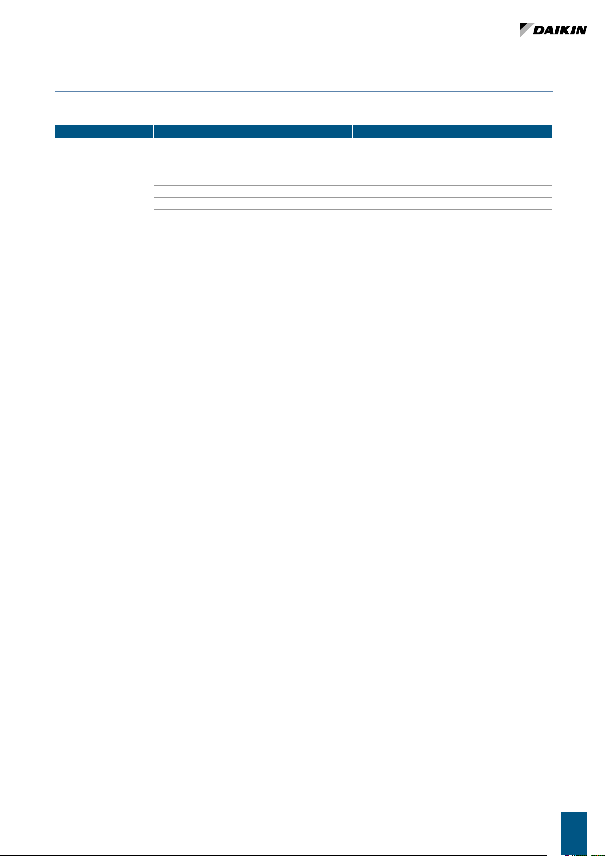
9 TROUBLESHOOTING
If the unit is not working properly, before calling a service engineer carry out the checks indicated in the table below.
PROBLEM CAUSE SOLUTION
No power supply Restore the power supply
The unit fails to work
The unit provides insufficient cooling
or heating
The unit “leaks” water
The automatic safety cutout has tripped Call a service centre for assistance
The on/off switch is on Start the unit by moving the switch to ON
The air filter is dirty or clogged Clean the air filter
An obstacle is obstructing the air intake or outlet Remove the obstacle
Air is trapped inside the heat exchanger Call the installer for assistance
There are open windows and/or doors Close windows and/or doors
The minimum speed has been selected Select medium or maximum speed
The unit has not been installed with the correct inclination Call the installer for assistance
The drainage outlet is clogged Call the installer for assistance
If the problem cannot be solved, contact your dealer or the nearest service centre.
UT66002770-02 9
Page 10
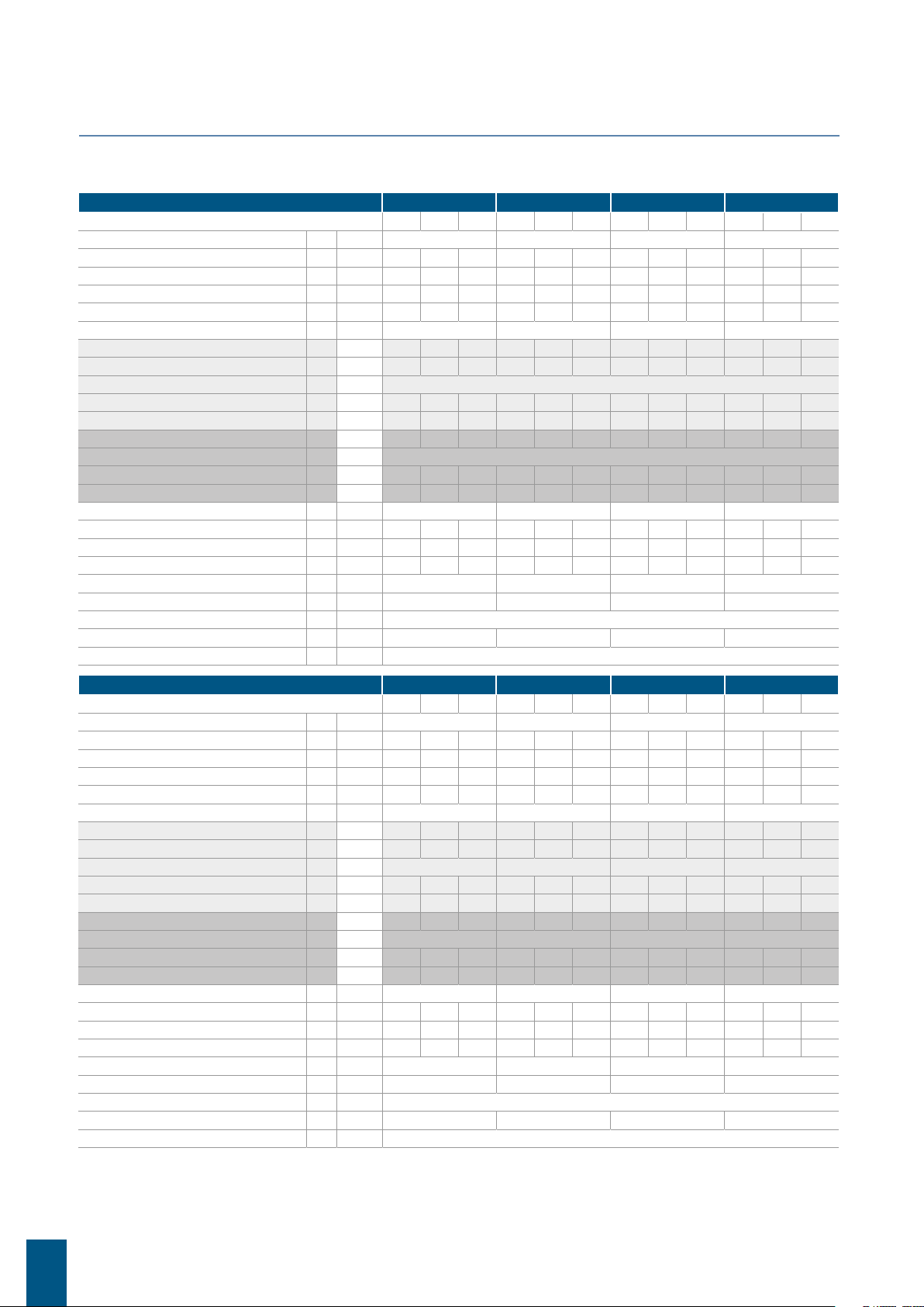
10 RATED TECHNICAL DATA
» 2 pipes
FWP-C 04 05 06 08
Speed
Declared speed
Control voltage (E) V
Rated air flow (E) m³/h
Available static pressure (E) Pa
Power input (E) W
Maximum current absorption A
Total cooling capacity (1)(E) kW
Sensible cooling capacity (1)(E) kW
FCEER class (E)
Water flow (2) l/h
Water pressure drop (2)(E) kPa
Heating capacity (3)(E) kW
FCCOP class (E)
Water flow (3) l/h
Water pressure drop (3)(E) kPa
Standard coil - number of rows
Total sound power level (4) dB(A)
Inlet + radiated sound power level (4)(E) dB(A)
Outlet sound power level (4)(E) dB(A)
Water content - standard coil dm³
Cross-section area of power cables (5) mm²
Power supply cable type
Safety fuse F A
Fuses type
min med max min med max min med max min med max
2,5,7 1,5,7 1,6,7 1,4,7
2,90 8,00 9,00 4,30 7,50 8,40 4,50 7,40 8,30 5,40 8,30 9,90
109 246 276 171 275 341 195 360 402 305 532 652
10 50 63 19 50 77 19 50 63 17 50 75
6 25 33 10 24 39 10 26 35 22 51 77
0,32 0,60 0,84 0,84
0,93 1,76 1,95 1,29 1,95 2,34 1,59 2,74 3,04 1,98 3,26 3,79
0,62 1,25 1,39 0,91 1,39 1,66 1,09 1,91 2,11 1,48 2,48 2,92
A
161 306 340 222 339 408 274 476 527 343 568 664
2 5 6 3 6 8 3 7 9 3 8 11
0,88 1,81 1,99 1,33 1,98 2,35 1,59 2,80 3,10 2,35 3,71 4,31
A
153 315 346 231 345 408 276 488 538 408 644 749
1 4 5 2 5 7 2 6 8 4 9 11
3 3 4 3
28 49 52 39 50 54 39 50 54 38 52 58
26 47 50 37 48 52 37 48 52 36 50 56
25 46 49 36 47 51 36 47 51 35 49 55
1,20 1,20 2,20 1,60
1,00 1,00 1,00 1,00
N07V-K
1 1 1 1
gG
FWP-C 10 11 15 17
Speed
Declared speed
Control voltage (E) V
Rated air flow (E) m³/h
Available static pressure (E) Pa
Power input (E) W
Maximum current absorption A
Total cooling capacity (1)(E) kW
Sensible cooling capacity (1)(E) kW
FCEER class (E)
Water flow (2) l/h
Water pressure drop (2)(E) kPa
Heating capacity (3)(E) kW
FCCOP class (E)
Water flow (3) l/h
Water pressure drop (3)(E) kPa
Standard coil - number of rows
Total sound power level (4) dB(A)
Inlet + radiated sound power level (4)(E) dB(A)
Outlet sound power level (4)(E) dB(A)
Water content - standard coil dm³
Cross-section area of power cables (5) mm²
Power supply cable type
Safety fuse F A
Fuses type
min med max min med max min med max min med max
1,6,7 1,6,7 5,6,7 5,6,7
3,40 7,60 8,50 3,40 7,60 8,50 6,80 7,50 8,30 6,80 7,50 8,30
333 687 760 333 687 760 1050 1163 1289 1050 1163 1289
12 50 61 12 50 61 40 50 60 40 50 60
11 54 68 11 54 68 105 128 162 105 128 162
0,91 0,91 3,52 3,52
2,29 4,34 4,75 2,51 4,91 5,35 6,28 6,81 7,38 7,04 7,64 8,28
1,67 3,21 3,51 1,77 3,45 3,76 4,64 5,03 5,46 4,96 5,38 5,84
A A C B
394 753 828 432 850 930 1094 1190 1295 1225 1332 1448
2 7 8 3 10 12 13 16 18 20 23 26
2,54 4,76 5,17 2,63 5,03 5,49 6,68 7,22 7,80 7,18 7,80 8,46
A A B B
441 827 898 457 875 955 1162 1256 1356 1248 1355 1471
2 7 8 3 9 11 12 14 16 17 19 22
3 4 3 4
38 55 58 38 55 58 61 63 69 61 63 69
36 53 56 36 53 56 59 61 67 59 61 67
35 52 55 35 52 55 58 60 66 58 60 66
2,50 3,30 2,50 3,30
1,00 1,00 1,50 1,50
N07V-K
1 1 2 2
gG
(1) Water temperature 7°C / 12°C, air temperature dry bulb 27°C, wet bulb 19°C (47% relative humidity) according to EN1397:2015
(2) Water temperature 7°C / 12°C, air temperature dry bulb 27°C, wet bulb 19°C (47% relative humidity)
(3) Water temperature 45°C / 40°C, air temperature 20°C
(4) Sound power measured according to standards ISO 3741 and ISO 3742
(5) Sound pressure measured at a distance of 4 m in a free field with a directivity factor of 1
(E) EUROVENT certified data
Power supply 230-1-50 (V-ph-Hz)
FWPC10
Page 11
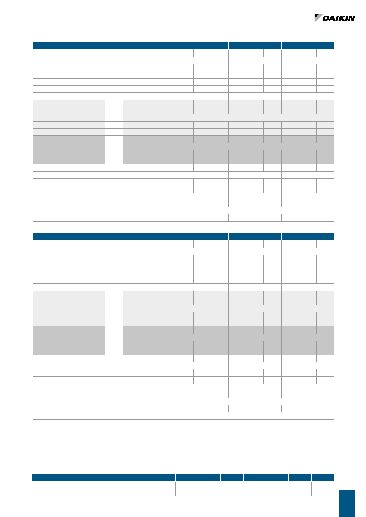
» 4 pipes
FWP-C 04 05 06 08
Speed
Declared speed
Control voltage (E) V
Rated air flow (E) m³/h
Available static pressure (E) Pa
Power input (E) W
Maximum current absorption A
Total cooling capacity (1)(E) kW
Sensible cooling capacity (1)(E) kW
FCEER class (E)
Water flow (2) l/h
Water pressure drop (2)(E) kPa
Heating capacity (3)(E) kW
FCCOP class (E)
Water flow (3) l/h
Water pressure drop (3)(E) kPa
Standard coil - number of rows
Total sound power level (4) dB(A)
Inlet + radiated sound power level (4)(E) dB(A)
Outlet sound power level (4)(E) dB(A)
Water content - standard coil dm³
Cross-section area of power cables (5) mm²
Power supply cable type
Safety fuse F A
Fuses type
min med max min med max min med max min med max
2,5,7 1,5,7 1,6,7 1,4,7
2,90 7,90 8,90 4,50 7,30 8,90 4,50 7,40 8,30 5,40 8,30 9,90
109 243 270 170 272 336 195 357 398 302 524 642
10 50 63 19 50 77 19 50 63 17 50 75
6 25 32 10 23 39 10 26 35 21 50 77
0,32 0,60 0,84 0,84
0,93 1,74 1,91 1,28 1,93 2,31 1,59 2,72 3,01 1,95 3,22 3,75
0,62 1,24 1,36 0,90 1,38 1,64 1,09 1,89 2,09 1,47 2,44 2,89
A
161 302 333 221 335 404 274 473 522 339 562 656
2 5 6 3 6 8 3 7 9 3 8 11
1,14 1,93 2,06 1,55 2,07 2,32 2,09 3,09 3,29 2,80 3,82 4,24
A
100 169 180 136 181 204 183 271 288 245 334 371
1 2 3 2 3 3 2 3 4 3 5 6
28 49 52 39 50 54 39 50 54 38 52 58
3+1 3+1 4+1 3+1
26 47 50 37 48 52 37 48 52 36 50 56
25 46 49 36 47 51 36 47 51 35 49 55
0,47 0,47 0,59 0,59
1,00 1,00 1,00 1,00
N07V-K
1 1 1 1
gG
FWP-C 10 11 15 17
Speed
Declared speed
Control voltage (E) V
Rated air flow (E) m³/h
Available static pressure (E) Pa
Power input (E) W
Maximum current absorption A
Total cooling capacity (1)(E) kW
Sensible cooling capacity (1)(E) kW
FCEER class (E)
Water flow (2) l/h
Water pressure drop (2)(E) kPa
Heating capacity (3)(E) kW
FCCOP class (E)
Water flow (3) l/h
Water pressure drop (3)(E) kPa
Standard coil - number of rows
Total sound power level (4) dB(A)
Inlet + radiated sound power level (4)(E) dB(A)
Outlet sound power level (4)(E) dB(A)
Water content - standard coil dm³
Cross-section area of power cables (5) mm²
Power supply cable type
Safety fuse F A
Fuses type
(1) Water temperature 7°C / 12°C, air temperature dry bulb 27°C, wet bulb 19°C (47% relative humidity) according to EN1397:2015
(2) Water temperature 7°C / 12°C, air temperature dry bulb 27°C, wet bulb 19°C (47% relative humidity)
(3) Water temperature 65°C / 55°C, air temperature 20°C
(4) Sound power measured according to standards ISO 3741 and ISO 3742
(5) Sound pressure measured at a distance of 4 m in a free field with a directivity factor of 1
(E) EUROVENT certified data
Power supply 230-1-50 (V-ph-Hz)
min med max min med max min med max min med max
1,6,7 1,6,7 5,6,7 5,6,7
3,40 7,60 8,50 3,40 7,60 8,50 6,80 7,50 8,30 6,80 7,50 8,30
333 683 755 333 683 755 1050 1163 1289 1050 1163 1289
12 50 61 12 50 61 40 50 60 40 50 60
11 54 67 11 54 67 105 128 162 105 128 162
0,91 0,91 3,52 3,52
2,29 4,32 4,72 2,51 4,88 5,32 6,28 6,81 7,38 7,04 7,64 8,28
1,67 3,19 3,48 1,77 3,43 3,74 4,64 5,03 5,46 4,96 5,38 5,84
A A C B
394 749 822 432 846 925 1094 1190 1295 1225 1332 1448
2 7 8 3 10 12 13 16 18 20 23 26
3,40 5,17 5,45 3,40 5,17 5,45 6,42 6,73 7,06 6,42 6,73 7,06
A A C C
297 452 477 297 452 477 562 589 618 562 589 618
6 13 14 6 13 14 19 21 22 19 21 22
38 55 58 38 55 58 61 63 69 61 63 69
3+1 4+1 3+1 4+1
36 53 56 36 53 56 59 61 67 59 61 67
35 52 55 35 52 55 58 60 66 58 60 66
0,97 0,97 0,97 0,97
1,00 1,00 1,50 1,50
N07V-K
1 1 2 2
gG
11 WEIGHTS
FWP-C 04 05 06 08 10 11 15 17
2 pipes kg 24,4 25,4 33,0 36,0 45,0 45,0 51,0 51,0
4 pipes kg 25,8 26,8 34,6 37,6 47,5 47,5 53,5 53,5
UT66002770-02 11
Page 12

deklaruje na własną i wyłączną odpowiedzialność, że modele klimatyzatorów, których dotyczy niniejsza deklaracja:
Enfocus Software - Customer Support
declară pe proprie răspundere că aparatele de aer condiţionat la care se referă această declaraţie:
z vso odgovornostjo izjavlja, da so modeli klimatskih naprav, na katere se izjava nanaša:
kinnitab oma täielikul vastutusel, et käesoleva deklaratsiooni alla kuuluvad kliimaseadmete mudelid:
декларира на своя отговорност, че моделите климатична инсталация, за които се отнася тази декларация:
visiška savo atsakomybe skelbia, kad oro kondicionavimo prietaisų modeliai, kuriems yra taikoma ši deklaracija:
ar pilnu atbildību apliecina, ka tālāk uzskaitīto modeļu gaisa kondicionētāji, uz kuriem attiecas šī deklarācija:
vyhlasuje na vlastnú zodpovednosť, že tieto klimatizačné modely, na ktoré sa vzťahuje toto vyhlásenie:
tamamen kendi sorumluluǧunda olmak üzere bu bildirinin ilgili olduǧu klima modellerinin aşaǧıdaki gibi olduǧunu beyan eder:
17
18
19
20
21
22
23
24
25
megfelelnek az alábbi szabvány(ok)nak vagy egyéb irányadó dokumentum(ok)nak, ha azokat előírás szerint használják:
spełniają wymogi następujących norm i innych dokumentów normalizacyjnych, pod warunkiem że używane są zgodnie z naszymi instrukcjami:
161718192021222324
Directivelor, cu amendamentele respective.
Direktive z vsemi spremembami.
Direktiivid koos muudatustega.
Директиви, с техните изменения.
Direktyvose su papildymais.
Direktīvās un to papildinājumos.
18192021222324
Direktiver, med senere ændringer.
10111213141516
sunt în conformitate cu următorul (următoarele) standard(e) sau alt(e) document(e) normativ(e), cu condiţia ca acestea să fie utilizate în conformitate cu
instrucţiunile noastre:
skladni z naslednjimi standardi in drugimi normativi, pod pogojem, da se uporabljajo v skladu z našimi navodili:
on vastavuses järgmis(t)e standardi(te)ga või teiste normatiivsete dokumentidega, kui neid kasutatakse vastavalt meie juhenditele:
съответстват на следните стандарти или други нормативни документи, при условие, че се използват съгласно нашите инструкции:
atitinka žemiau nurodytus standartus ir (arba) kitus norminius dokumentus su sąlyga, kad yra naudojami pagal mūsų nurodymus:
tad, ja lietoti atbilstoši ražotāja norādījumiem, atbilst sekojošiem standartiem un citiem normatīviem dokumentiem:
sú v zhode s nasledovnou(ými) normou(ami) alebo iným(i) normatívnym(i) dokumentom(ami), za predpokladu, že sa používajú v súlade snašim
návodom:
ürünün, talimatlarımıza göre kullanılması koşuluyla aşağıdaki standartlar ve norm belirten belgelerle uyumludur:
25
Directives, as amended.
010203040506070809
Smernice, v platnom znení.
Direktiv, med företagna ändringar.
Direktiver, med foretatte endringer.
Direktiivejä, sellaisina kuin ne ovat muutettuina.
v platném znění.
Smjernice, kako je izmijenjeno.
irányelv(ek) és módosításaik rendelkezéseit.
Direktiven, gemäß Änderung.
Directives, telles que modifiées.
Richtlijnen, zoals geamendeerd.
Directivas, según lo enmendado.
Direttive, come da modifica.
Οδηγιών, όπως έχουν τροποποιηθεί.
**
Değiştirilmiş halleriyle Yönetmelikler.
25
———
<A>
<B>
<C>
z późniejszymi poprawkami.
17
както е изложено в <A> и оценено положително от <B>
съгласно Сертификата<C>.
kaip nustatyta <A> ir kaip teigiamai nuspręsta <B> pagal
Sertifikatą<C>.
kā norādīts <A> un atbilstoši <B> pozitīvajam vērtējumam
saskaņā ar sertifikātu<C>.
ako bolo uvedené v <A> a pozitívne zistené <B> vsúlade
s osvedčením<C>.
<A>’da belirtildiği gibi ve <C>Sertifikasına göre <B>
tarafından olumlu olarak değerlendirildiği gibi.
Directivas, conforme alteração em.
Директив со всеми поправками.
21Забележка*
22Pastaba*
23Piezīmes*
24Poznámka*
25Not*
a(z) <A> alapján, a(z) <B> igazolta a megfelelést, a(z)
<C>tanúsítvány szerint.
zgodnie z dokumentacją <A>, pozytywną
opinią <B> i Świadectwem<C>.
aşa cum este stabilit în <A> şi apreciat pozitiv de<B>
în conformitate cu Certificatul<C>.
kot je določeno v <A> in odobreno s strani <B>
vskladu scertifikatom<C>.
nagu on näidatud dokumendis <A> ja heaks kiidetud
<B> järgi vastavalt sertifikaadile<C>.
16Megjegyzés*
17Uwaga*
18Notă*
19Opomba*
20Märkus*
Daikin Europe N.V. je pooblaščen za sestavo datoteke s tehnično mapo.
Daikin Europe N.V. on volitatud koostama tehnilist dokumentatsiooni.
Daikin Europe N.V. е оторизирана да състави Акта за техническа конструкция.
Daikin Europe N.V. yra įgaliota sudaryti šį techninės konstrukcijos failą.
Daikin Europe N.V. ir autorizēts sastādīt tehnisko dokumentāciju.
Spoločnosť Daikin Europe N.V. je oprávnená vytvoriť súbor technickej konštrukcie.
Daikin Europe N.V. Teknik Yapı Dosyasını derlemeye yetkilidir.
19**
20**
21**
22**
23**
24**
25**
Daikin Europe N.V. on valtuutettu laatimaan Teknisen asiakirjan.
Společnost Daikin Europe N.V. má oprávnění ke kompilaci souboru technické konstrukce.
Daikin Europe N.V. je ovlašten za izradu Datoteke o tehničkoj konstrukciji.
A Daikin Europe N.V. jogosult a műszaki konstrukciós dokumentáció összeállítására.
Daikin Europe N.V. ma upoważnienie do zbierania i opracowywania dokumentacji konstrukcyjnej.
Daikin Europe N.V. este autorizat să compileze Dosarul tehnic de construcţie.
13**
14**
15**
16**
17**
18**
заявляет, исключительно под свою ответственность, что модели кондиционеров воздуха, к которым относится настоящее заявление:
erklærer under eneansvar, at klimaanlægmodellerne, som denne deklaration vedrører:
deklarerar i egenskap av huvudansvarig, att luftkonditioneringsmodellerna som berörs av denna deklaration innebär att:
erklærer et fullstendig ansvar for at de luftkondisjoneringsmodeller som berøres av denne deklarasjon, innebærer at:
ilmoittaa yksinomaan omalla vastuullaan, että tämän ilmoituksen tarkoittamat ilmastointilaitteiden mallit:
prohlašuje ve své plné odpovědnosti, že modely klimatizace, k nimž se toto prohlášení vztahuje:
izjavljuje pod isključivo vlastitom odgovornošću da su modeli klima uređaja na koje se ova izjava odnosi:
teljes felelőssége tudatában kijelenti, hogy a klímaberendezés modellek, melyekre e nyilatkozat vonatkozik:
09
10
11
12
13
14
15
16
estão em conformidade com a(s) seguinte(s) norma(s) ou outro(s) documento(s) normativo(s), desde que estes sejam utilizados de
acordo com as nossas instruções:
соответствуют следующим стандартам или другим нормативным документам, при условии их использования согласно нашим инструкциям:
overholder følgende standard(er) eller andet/andre retningsgivende dokument(er), forudsat at disse anvendes i henhold til vore instrukser:
respektive utrustning är utförd i överensstämmelse med och följer följande standard(er) eller andra normgivande dokument, under förutsättning att
användning sker i överensstämmelse med våra instruktioner:
respektive utstyr er i overensstemmelse med følgende standard(er) eller andre normgivende dokument(er), under forutssetning av at disse brukes i
henhold til våre instrukser:
vastaavat seuraavien standardien ja muiden ohjeellisten dokumenttien vaatimuksia edellyttäen, että niitä käytetään ohjeidemme mukaisesti:
za předpokladu, že jsou využívány v souladu s našimi pokyny, odpovídají následujícím normám nebo normativním dokumentům:
08091011121314
u skladu sa slijedećim standardom(ima) ili drugim normativnim dokumentom(ima), uz uvjet da se oni koriste u skladu s našim uputama:
15
Machinery 2006/42/EC
Low Voltage 2014/35/EU
enligt <A> och godkänts av <B> enligt
Certifikatet<C>.
som det fremkommer i <A> og gjennom positiv
bedømmelse av <B> ifølge Sertifikat<C>.
jotka on esitetty asiakirjassa <A> ja jotka <B>
Electromagnetic Compatibility 2014/30/EU
ob upoštevanju določb:
vastavalt nõuetele:
следвайки клаузите на:
laikantis nuostatų, pateikiamų:
ievērojot prasības, kas noteiktas:
održiavajúc ustanovenia:
19202122232425
under iagttagelse af bestemmelserne i:
101112131415161718
bunun koşullarına uygun olarak:
enligt villkoren i:
gitt i henhold til bestemmelsene i:
noudattaen määräyksiä:
za dodržení ustanovení předpisu:
prema odredbama:
követi a(z):
zgodnie z postanowieniami Dyrektyw:
în urma prevederilor:
on hyväksynyt Sertifikaatin<C> mukaisesti.
11Information*
12Merk*
13Huom*
delineato nel <A> e giudicato positivamente da<B>
secondo il Certificato<C>.
όπως καθορίζεται στο <A> και κρίνεται θετικά
από το <B> σύμφωνα με το Πιστοποιητικό<C>.
tal como estabelecido em <A> e com o parecer positivo
de <B> de acordo com o Certificado<C>.
06Nota*
07Σημείωση*
08Nota*
jak bylo uvedeno v <A> a pozitivně zjištěno
<B> vsouladu sosvědčením<C>.
kako je izloženo u <A> i pozitivno ocijenjeno odstrane
<B> prema Certifikatu<C>.
14Poznámka*
15Napomena*
Η Daikin Europe N.V. είναι εξουσιοδοτημένη να συντάξει τον Τεχνικό φάκελο κατασκευής.
A Daikin Europe N.V. está autorizada a compilar a documentação técnica de fabrico.
Компания Daikin Europe N.V. уполномочена составить Комплект технической документации.
Daikin Europe N.V. er autoriseret til at udarbejde de tekniske konstruktionsdata.
Daikin Europe N.V. är bemyndigade att sammanställa den tekniska konstruktionsfilen.
Daikin Europe N.V. har tillatelse til å kompilere den Tekniske konstruksjonsfilen.
07**
08**
09**
10**
11**
12**
как указано в <A> и в соответствии сположительным
решением <B> согласно Свидетельству<C>.
som anført i <A> og positivt vurderet af <B> ihenhold til
Certifikat<C>.
09Примечание*
10Bemærk*
Hiromitsu Iwasaki
Director
Ostend, 14th of December 2020
declares under its sole responsibility that the air conditioning models to which this declaration relates:
erklärt auf seine alleinige Verantwortung daß die Modelle der Klimageräte für die diese Erklärung bestimmt ist:
déclare sous sa seule responsabilité que les appareils d'air conditionné visés par la présente déclaration:
verklaart hierbij op eigen exclusieve verantwoordelijkheid dat de airconditioning units waarop deze verklaring betrekking heeft:
declara baja su única responsabilidad que los modelos de aire acondicionado a los cuales hace referencia la declaración:
dichiara sotto sua responsabilità che i condizionatori modello a cui è riferita questa dichiarazione:
δηλώνει με αποκλειστική της ευθύνη ότι τα μοντέλα των κλιματιστικών συσκευών στα οποία αναφέρεται η παρούσα δήλωση:
declara sob sua exclusiva responsabilidade que os modelos de ar condicionado a que esta declaração se refere:
02
03
04
05
06
07
Daikin Europe N.V.
CE - DECLARATION-OF-CONFORMITY CE - DECLARACION-DE-CONFORMIDAD CE - DECLARAÇÃO-DE-CONFORMIDADE CE - ERKLÆRING OM-SAMSVAR CE - IZJAVA-O-USKLAĐENOSTI CE - IZJAVA O SKLADNOSTI CE - ATITIKTIES-DEKLARACIJA
CE - KONFORMITÄTSERKLÄRUNG CE - DICHIARAZIONE-DI-CONFORMITA CE - ЗАЯВЛЕНИЕ-О-СООТВЕТСТВИИ CE - ILMOITUS-YHDENMUKAISUUDESTA CE - MEGFELELŐSÉGI-NYILATKOZAT CE - VASTAVUSDEKLARATSIOON CE - ATBILSTĪBAS-DEKLARĀCIJA
CE - DECLARATION-DE-CONFORMITE CE - ΔHΛΩΣΗ ΣΥΜΜΟΡΦΩΣΗΣ CE - OVERENSSTEMMELSESERKLÆRING CE - PROHLÁŠENÍ-O-SHODĚ CE - DEKLARACJA-ZGODNOŚCI CE - ДЕКЛАРАЦИЯ-ЗА-СЪОТВЕТСТВИЕ CE - VYHLÁSENIE-ZHODY
CE - CONFORMITEITSVERKLARING CE - FÖRSÄKRAN-OM-ÖVERENSTÄMMELSE CE - DECLARAŢIE-DE-CONFORMITATE CE - UYGUNLUK-BEYANI
01
08
FWP04CAT*6V3***, FWP05CAT*6V3***, FWP06CAT*6V3***, FWP08CAT*6V3***, FWP10CAT*6V3***, FWP11CAT*6V3***, FWP15CAT*6V3***, FWP17CAT*6V3***,
FWP04CAF*6V3***, FWP05CAF*6V3***, FWP06CAF*6V3***, FWP08CAF*6V3***, FWP10CAF*6V3***, FWP11CAF*6V3***, FWP15CAF*6V3***, FWP17CAF*6V3***,
are in conformity with the following standard(s) or other normative document(s), provided that these are used in accordance with our instructions:
der/den folgenden Norm(en) oder einem anderen Normdokument oder -dokumenten entspricht/entsprechen, unter der Voraussetzung, daß sie gemäß
unseren Anweisungen eingesetzt werden:
sont conformes à la/aux norme(s) ou autre(s) document(s) normatif(s), pour autant qu'ils soient utilisés conformément à nos instructions:
conform de volgende norm(en) of één of meer andere bindende documenten zijn, op voorwaarde dat ze worden gebruikt overeenkomstig onze
instructies:
están en conformidad con la(s) siguiente(s) norma(s) u otro(s) documento(s) normativo(s), siempre que sean utilizados de acuerdo con nuestras
instrucciones:
FWP04CAG*6V3***, FWP05CAG*6V3***, FWP06CAG*6V3***, FWP08CAG*6V3***, FWP10CAG*6V3***, FWP11CAG*6V3***, FWP15CAG*6V3***, FWP17CAG*6V3***,
* = , , 0, 1, 2, 3, ..., 9, A, B, C, ..., Z
01020304050607
sono conformi al(i) seguente(i) standard(s) o altro(i) documento(i) a carattere normativo, a patto che vengano usati in conformità alle nostre istruzioni:
as set out in <A> and judged positively by <B>
according to the Certificate<C>.
wie in <A> aufgeführt und von <B> positiv
beurteilt gemäß Zertifikat<C>.
tel que défini dans <A> et évalué positivement par <B>
είναι σύμφωνα με το(α) ακόλουθο(α) πρότυπο(α) ή άλλο έγγραφο(α) κανονισμών, υπό την προϋπόθεση ότι χρησιμοποιούνται
σύμφωνα με τις οδηγίες μας:
following the provisions of:
EN60335-1: 2013/EC: 2014/A11: 2015, EN60335-2-40: 2005/A1: 2007/A2: 2009, EN55014-1: 2008 + A1: 2010 + A2: 2012, EN55014-2: 1998 + A1: 2002 + A2: 2009, EN55014-2: 2015, EN55016-2-3: 2006, EN61000-3-2: 2007 +
A1: 2011 + A2: 2011, EN61000-3-2: 2014, EN61000-3-3: 2009, EN61000-3-3: 2013, EN61000-4-2: 2011, EN61000-4-3: 2007 + A1: 2011, EN61000-4-4: 2006 + A1: 2010, EN61000-4-5: 2014, EN61000-4-6: 2014, EN61000-4-11:
2006,
010203040506070809
gemäß den Vorschriften der:
conformément aux stipulations des:
overeenkomstig de bepalingen van:
siguiendo las disposiciones de:
secondo le prescrizioni per:
με τήρηση των διατάξεων των:
de acordo com o previsto em:
в соответствии с положениями:
01Note*
02Hinweis*
03Remarque*
conformément au Certificat<C>.
zoals vermeld in <A> en positief beoordeeld door <B>
overeenkomstig Certificaat<C>.
04Bemerk*
como se establece en <A> y es valorado
positivamente por <B> de acuerdo con el
Certificado<C>.
Daikin Europe N.V. is authorised to compile the Technical Construction File.
Daikin Europe N.V. hat die Berechtigung die Technische Konstruktionsakte zusammenzustellen.
Daikin Europe N.V. est autorisé à compiler le Dossier de Construction Technique.
01**
02**
05Nota*
03**
Daikin Europe N.V. is bevoegd om het Technisch Constructiedossier samen te stellen.
Daikin Europe N.V. está autorizado a compilar el Archivo de Construcción Técnica.
Daikin Europe N.V. è autorizzata a redigere il File Tecnico di Costruzione.
04**
05**
06**
2PW59562-11F
Page 13

INDICE GENERALE
1 PRIMA DI INIZIARE L’INSTALLAZIONE . . . . . . .p. 14
2 UTILIZZO PREVISTO . . . . . . . . . . . . . . . . . . . . . . . . . .p. 14
LUOGO DI INSTALLAZIONE . . . . . . . . . . . . . . . . . . . . . . p. 14
3 DESCRIZIONE DELL'APPARECCHIO . . . . . . . . . .p. 14
3.1 MODULAZIONE ED EFFICIENZA AD INCASSO A
SOFFITTO . . . . . . . . . . . . . . . . . . . . . . . . . . . . . . . . . . . . . . .p. 14
3.2 COMPONENTI PRINCIPALI. . . . . . . . . . . . . . . . . . . . . . . .p. 15
ACCESSORI . . . . . . . . . . . . . . . . . . . . . . . . . . . . . . . . . . . . . .p. 15
4 DATI DIMENSIONALI . . . . . . . . . . . . . . . . . . . . . . . . . . p. 16
5 INSTALLAZIONE. . . . . . . . . . . . . . . . . . . . . . . . . . . . . . . p. 16
AVVERTENZE PER L'INSTALLAZIONE. . . . . . . . . . . . . .p. 16
5.1 MONTAGGIO UNITÀ . . . . . . . . . . . . . . . . . . . . . . . . . . . . . p. 17
6 VERIFICA FUNZIONALE. . . . . . . . . . . . . . . . . . . . . . . p. 17
7 USO . . . . . . . . . . . . . . . . . . . . . . . . . . . . . . . . . . . . . . . . . . . .p. 18
8 MANUTENZIONE. . . . . . . . . . . . . . . . . . . . . . . . . . . . . .p. 18
PULIZIA DEL FILTRO ARIA. . . . . . . . . . . . . . . . . . . . . . . .p. 18
PULIZIA DELLA BATTERIA DI SCAMBIO TERMICO
. . . . . . . . . . . . . . . . . . . . . . . . . . . . . . . . . . . . . . . . . . . . . . . . .p. 18
9 RICERCA DEI GUASTI. . . . . . . . . . . . . . . . . . . . . . . . . .p. 19
IT
10 DATI TECNICI NOMINALI. . . . . . . . . . . . . . . . . . . . . .p. 20
11 PESI . . . . . . . . . . . . . . . . . . . . . . . . . . . . . . . . . . . . . . . . . . . .p. 20
LIMITI DI FUNZIONAMENTO
Fluido termovettore: acqua
Temperatura acqua: 5 °C ÷ 95 °C
Temperatura aria: -20 °C ÷ 40 °C
Tensione di alimentazione: 230 V +/-10 %
Massima pressione di esercizio: 16 bar
Limite di umidità relativa dell'aria ambiente: RH<85%
non condensante
Page 14

1 PRIMA DI INIZIARE L’INSTALLAZIONE
Leggere attentamente questo manuale.
L'installazione e la manutenzione dell'apparecchio devono essere
eettuati esclusivamente da personale tecnico qualicato per questo tipo di macchina, in conformità con le normative vigenti.
Al ricevimento dell'apparecchio, controllarne lo stato vericando
ATTENZIONE: I prodotti elettrici ed elettronici non possono es-
sere mescolati con i riuti casalinghi non separati. NON provate
a smantellare il sistema da soli: lo smantellamento del sistema, il
trattamento dell'olio e di altre parti, dev'essere eettuato da un
che non abbia subito danni dovuti al trasporto.
Per l'installazione e l'uso di eventuali accessori, si rimanda alle relative schede tecniche.
Individuare il modello di ventilconvettore FWP-C dalle indicazioni
riportate sull'imballo.
SIMBOLI DI SICUREZZA
Leggere attentamente il manuale
Attenzione
Utilizzare dispositivi di protezione individuale
UTILIZZARE DPI ADEGUATI GUANTI PER REFRIGERANTE,
OCCHIALI DI PROTEZIONE
installatore autorizzato e deve rispettare la legislazione applicabile. Le unità devono essere trattate presso un impianto specializzato di lavorazione per il riutilizzo, il riciclaggio e il recupero.
Assicurandovi che questo prodotto sia smaltito correttamente,
aiuterete a prevenire possibili conseguenze negative per l'ambiente e la salute umana. Per ulteriori informazioni contattate il
vostro installatore o l'autorità locale.
ATTENZIONE: l'unità non ha componenti pericolosi secondo la
classicazione del Regolamento 1357/2014.
2 UTILIZZO PREVISTO
La Daikin si ritiene sollevata da ogni responsabilità nei casi in cui
l'apparecchio sia installato da personale non qualicato, venga utilizzato impropriamente o in condizioni non ammesse, non venga
eettuata manutenzione prevista dal presente manuale o non siano
LUOGO DI INSTALLAZIONE
Nella scelta del luogo di installazione osservare i seguenti punti:
l'apparecchio di climatizzazione non deve essere posto imme-
diatamente sotto una presa di corrente
non installare l'unità in ambienti con presenza di gas o polveri
inammabili
non esporre l'unità a spruzzi d'acqua; non installare in locale
stai utilizzati ricambi originali.
Apparecchi progettati per la climatizzazione dell'aria ambiente e
destinati all'utilizzo in applicazioni di comfort civile.
lavanderia
installare il ventilconvettore su pareti o sotti che ne reggano il
peso mantenendo intorno uno spazio suciente a garantirne il
buon funzionamento e le operazioni di manutenzione
conservare l'unità nell'imballo no al momento dell'installazio-
ne per evitare inltrazioni di polvere nel suo interno
3 DESCRIZIONE DELL'APPARECCHIO
MODULAZIONE ED EFFICIENZA AD INCASSO A SOFFITTO
FWP-C rappresenta il completamento della gamma con l'utilizzo
della tecnologia EC inverter sui motori elettrici. Alle peculiarità di
FWP-C si sommano i beneci della tecnologia brushless in termini di
riduzione dei consumi elettrici e conseguente riduzione delle emis
sioni di CO2, aumento della essibilità di funzionamento grazie alla
modulazione della portata aria ed aumento del livello di comfort
termoigrometrico ed acustico.
La gamma è composta da 8 modelli che coprono un range di porta
ta aria da 300 a 1200 m³/h.
La modulazione continua della portata aria e l'utilizzo di scambiato
ri di calore ad alta ecienza consente di operare anche con dierenze di temperatura aria – acqua contenute.
Gli scambiatori di calore possono inoltre essere ottimizzati nella cir
cuitazione per applicazioni centralizzate quali district cooling.
-
-
-
FWPC14
Page 15
COMPONENTI PRINCIPALI
Struttura
Realizzata in lamiera di acciaio zincato, isolata termicamente ed acusticamente con pannelli autoestinguenti di classe 1. Altezza ridotta
per agevolare l'installazione in posizione orizzontale, in controsoftto. La struttura contiene la vasca di raccolta e scarico condensa.
La vasca principale di raccolta della condensa è posta internamente
alla struttura dell'unità ed è a pressione positiva rispetto allo scarico
per facilitare il drenaggio della condensa.
Batteria di scambio termico
Standard a 3 ranghi, disponibile a 4 ranghi su richiesta, ad alta efcienza, in tubo di rame ed alette in alluminio bloccate ai tubi mediante espansione meccanica. È corredata di collettori in ottone e
valvola di sato aria. La batteria, normalmente fornita con attacchi
a sinistra, può essere ruotata di 180°. Su richiesta sono disponibi
li batterie ad alta ecienza ottimizzate per le applicazioni district
cooling.
Ventilatori
Ventole centrifughe a doppia aspirazione realizzate in ABS o alluminio, a pale avanti, bilanciate staticamente e dinamicamente,
ACCESSORI
Pannelli di comando elettronici a microprocessore con display
FWECSAP Scheda di potenza per comando FWCS
FWECSAC Interfaccia utente con display per comando FWCS
FWEC3AA Comando a microprocessore con display FWEC3AA
FWHSKA Sonda umidità per comandi FWEC 2, FWEC3AA, FWECS
FWTSKA Sonda acqua per comandi FWEC , FWECS
Bacinelle ausiliarie di raccolta condensa, gusci isolanti, pompa scarico condensa
CDRP1A Kit pompa di scarico condensa
Resistenze elettriche
EH Resistenza elettrica con kit di montaggio, scatola relè e sicurezze
Accessori vari
EDPD
EPIMSB6
Valvole
Valvole a 2 vie, attuatori ON/OFF o MODULANTI, alimentazione 230 V o 24 V, kit idraulici, per batteria
addizionale
Valvole a 2 vie, attuatori ON/OFF o MODULANTI, alimentazione 230 V o 24 V, kit idraulici, per batteria
principale
Valvole a 3 vie, attuatori ON/OFF o MODULANTI, alimentazione 230 V o 24 V, kit idraulici, per batteria
addizionale
Valvole a 3 vie, attuatori ON/OFF o MODULANTI, alimentazione 230 V o 24 V, kit idraulici, per batteria
principale
Valvole a 2 vie pressure independent, attuatori ON/OFF o MODULANTI, alimentazione 230V o 24V, kit
idraulici, per batteria principale e addizionale
Bacinella ausiliaria di raccolta condensa
Interfaccia di potenza per il collegamento in parallelo fino a 4 ventilconvettori ad un unico
comando
accoppiate direttamente al motore elettrico.
Motore EC
Motore elettrico multi-velocità, dl tipo asincrono monofase, con
condensatore permanentemente inserito e protettore termico,
montato su supporti antivibranti.
Filtro aria
Filtro aria rigenerabile in bra acrilica, classe di ltrazione G3, posto
sull'aspirazione dell'aria, estraibile a cassetto dal basso.
Aspirazione aria
Aspirazione dell'aria dalla parte frontale o inferiore della macchina,
in base alle esigenze impiantistiche.
-
Esempio di installazione
La struttura permette di combinare un'ampia gamma di accessori in ripresa e mandata no ad ottenere la congurazione ottimale
dell'unità.
UT66002770-02 15
Page 16
4 DATI DIMENSIONALI
Nella gura p.60-61 sono riportati i dati dimensionali di FWP-C e le posizioni degli attacchi idraulici.
5 INSTALLAZIONE
ATTENZIONE: l'installazione e l'avviamento dell'unità devono
essere eettuati da personale competente, secondo le regole
della corretta pratica impiantistica, in conformità alle normative
vigenti.
ATTENZIONE: Installare l'unità canalizzabile, l'interruttore di
linea (IL), e/o gli eventuali comandi a distanza in una posizione
non raggiungibile da persone che si trovino nella vasca da
bagno o nella doccia.
AVVERTENZA: È consigliabile installare gli eventuali acces
sori sull'apparecchio standard, prima di provvedere al posizionamento dello stesso, riferendosi alle schede tecniche.
AVVERTENZE PER L'INSTALLAZIONE
Alcune regole da seguire
Eettuare lo sfogo dell'aria dallo scambiatore, a pompe ferme,
agendo sulle valvole di sato poste a anco agli attacchi della
batteria stessa.
Le canalizzazioni, in particolare quella di mandata, dovranno
essere coibentate con materiale anticondensa.
Prevedere in prossimità dell'apparecchio un pannello di ispezio
ne per le operazioni di manutenzione e pulizia.
Installare il pannello di comando sulla parete; scegliere una po-
sizione facilmente accessibile per l'impostazione delle funzioni e, se prevista, ecace per la rilevazione della temperatura.
Evitare posizioni esposte direttamente all'irraggiamento solare,
posizioni soggette a correnti dirette di aria calda o fredda e di
interporre ostacoli che impediscano la rilevazione corretta della
temperatura.
AVVERTENZA:
Nel funzionamento normale, in particolare con ventilatore alla
velocità minima ed aria ambiente con elevata umidità relativa, è
possibile che si verichi formazione di condensa sulla mandata
aria e su alcune parti della struttura esterna dell'apparecchio.
Per evitare tali fenomeni, sempre rimanendo all'interno dei li
miti di lavoro previsti per l'apparecchio, è necessario limitare
la temperatura dell'acqua in ingresso all'interno dello scambiatore. In particolare occorre che la dierenza fra la temperatura di rugiada dell'aria (TA,DP) e la temperatura dell'acqua in
ingresso (TW) NON sia superiore a 14 °C, secondo la relazione:
TW>TA,DP-14 °C
Esempio: nel caso di aria ambiente a 25°C con il 75% di umidità
relativa il valore di temperatura di rugiada è pari a circa 20 °C e
dunque la temperatura dell'acqua in ingresso in batteria dovrà
essere superiore a:
20-14 = 6 °C al ne di evitare fenomeni di condensa su fancoil
provvisto di valvola.
20-12 = 8 °C qualora non si possa installare l'accessorio kit val-
vole.
L'aspirazione e la mandata sono a sezione rettangolare, con
foratura predisposta per il ssaggio degli accessori disponibili.
È possibile orientare gli attacchi dello scambiatore sul lato opposto
operando, come segue (p. 62):
smontare pannello anteriore superiore.
smontare la vasca di raccolta condensa.
smontare la batteria agendo sulle viti di ssaggio (2 per ogni
ancata).
ruotare la batteria di 180° (sull'asse verticale) e ssarla nuova
-
mente all'unità.
rimontare vasca e chiusura.
Fan coil con valvola
T aria bulbo secco [°C]
21 23 25 27 29 31 33
40 5 5 5 5 5 5 5
50 5 5 5 5 5 6 8
-
-
Umidità
relativa %
Umidità
relativa %
In caso di sosta prolungata del terminale, con ventilatore fermo
e circolazione di acqua fredda nello scambiatore, è possibile che
60 5 5 5 5 7 9 11
70 5 5 6 8 9 11 13
80 5 6 8 10 12 14 16
90 6 8 10 12 14 16 18
Fan coil senza valvola
T aria bulbo secco [°C]
21 23 25 27 29 31 33
40 6 6 6 6 6 6 6
50 6 6 6 6 6 8 10
60 6 6 6 7 9 11 13
70 6 6 8 10 11 13 15
80 6 8 10 12 12 16 18
90 8 10 12 14 14 18 20
si formi condensa anche all'esterno dell'apparecchio. In questo
caso è consigliabile installare l'accessorio valvola a 3 vie (o 2 vie)
in modo da interrompere il usso d'acqua in batteria quando il
ventilatore è fermo.
Nel caso di fermate invernali scaricare l'acqua dall'impianto onde
evitare danneggiamenti dovuti a formazione di ghiaccio; se vengono utilizzate soluzioni antigelo vericare il punto di congelamento
utilizzando la tabella riportata di seguito.
% glicole in peso
0 0 1,00 1,00
10 -4 0,97 1,05
20 -10 0,92 1,10
30 -16 0,87 1,15
40 -24 0,82 1,20
Temperatura
congelamento (°C)
Variazione potenza
resa
Variazione perdita
di carico
-
Collegamenti elettrici
Eettuare i collegamenti elettrici in assenza di tensione, secondo le
FWPC16
Page 17

normative di sicurezza vigenti.
I cablaggi dovranno essere eseguiti esclusivamente da personale
qualicato.
Per ogni unità termoventilante prevedere sulla rete di alimentazione un interruttore (IL) con contatti di apertura con distanza di almeno 3 mm e un fusibile (F) di protezione adeguato.
Gli assorbimenti elettrici sono riportati sull'etichetta dei dati di targa
applicata sull'unità.
In corso di installazione, seguire scrupolosamente lo schema elettrico relativo alla combinazione unità-pannello di comando.
5.1 MONTAGGIO UNITÀ
Fissaggio dell'unità
Inserire gli antivibranti forniti a corredo nelle 4 asole individuate per
il ssaggio al sotto.
Fissare l'unità base al sotto o alla parete utilizzando le 4 asole
predisposte.
Si consiglia di utilizzare barre lettate 8MA, tasselli adeguati al
peso della macchina stessa, e di preparare il posizionamento
della macchina utilizzando 3 bulloni 8MA (2 nella parte inferio
re, 1 nella parte superiore come indicato in gura p. 63) ed due
rondelle per ciasuna barra. Prima di stringere il controdado, regolare la chiusura del dado principale in modo da dare all'apparecchio una pendenza corretta, tale cioè da agevolare lo scarico
-
FWP-C + FWEC3A (motore incorporato) p.64
FWP-C + FWEC3A (motore separato) p.65
FWP-C + FWECS p.66
NOTA: I cavi elettrici (alimentazione e comando) devono essere
portati in morsettiera attraverso il fermacavo che si trova sulla
ancata opposta del lato attacchi idraulici.
ATTENZIONE: Il cavo COMUNE del motore è quello di colore
BIANCO: il suo errato collegamento provoca danni irreparabili
al motore.
della condensa (gura p. 63Scarico condensa). Una pendenza
corretta si ottiene inclinando verso il basso l'aspirazione rispetto
alla mandata, no ad ottenere un dislivello di circa 10 mm fra le
due estremità. Realizzare i collegamenti idraulici alla batteria di
scambio termico e, nel caso di funzionamento in fase di rareddamento, allo scarico condensa. Utilizzare uno dei due scarichi
della vasca, che si vedono all'esterno delle ancate dell'unità.
Per collegare l'unità alla linea di scarico condensa, utilizzare tu-
bo essibile in gomma e ssarlo al tubo di scarico prescelto (ø
3/8'') mediante una fascetta metallica (utilizzare lo scarico che si
trova sul lato attacchi idraulici).
6 VERIFICA FUNZIONALE
Vericare che l'apparecchio sia installato in modo da garantire
l'inclinazione richiesta.
Vericare che lo scarico condensa non sia ostruito (da depositi
di calcinacci ecc.).
Controllare la tenuta dei collegamenti idraulici.
Controllare che i cablaggi elettrici siano ben saldi (eseguire il
controllo in assenza di tensione).
Assicurarsi che sia stata eliminata l'aria dallo scambiatore di ca-
lore.
Dare tensione all'apparecchio e vericarne il funzionamento.
UT66002770-02 17
Page 18

7 USO
Per l'utilizzo dell'unità riferirsi alle istruzioni del pannello di comando, disponibile come accessorio.
ATTENZIONE: Per motivi di sicurezza, non introdurre mani o
oggetti nella griglia di uscita dell'aria.
PERICOLO: L’apparecchio può essere utilizzato da bambini di
età non inferiore a 8 anni e da persone con ridotte capacità
8 MANUTENZIONE
Per motivi di sicurezza, prima di compiere qualsiasi manutenzione o pulizia, spegnere l'apparecchio ponendo il commutatore di velocità su "Arresto" e l'interruttore di linea su 0 (OFF).
PERICOLO! Prestare attenzione durante le operazioni di ma
nutenzione: alcune parti metalliche possono provocare ferite:
dotarsi di guanti protettivi.
Le unità canalizzabili FWP-C richiedono operazioni di manutenzio
ne limitate alla pulizia periodica del ltro aria, dello scambiatore di
PULIZIA DEL FILTRO ARIA
Togliere tensione all'unità, ponendo l'interruttore di linea su 0 (OFF).
Per la pulizia del ltro aria procedere nel seguente modo:
1. Accedere all'apparecchio attraverso il pannello di ispezione ed
estrarre il ltro aria come indicato in gura (p.67Pulizia ltro
aria):
2. Se invece il ltro si trova all'interno della griglia di aspirazione,
-
-
siche, sensoriali o mentali, o prive di esperienza o della necessaria conoscenza, purché sotto sorveglianza oppure dopo che le
stesse abbiano ricevuto istruzioni relative all’uso sicuro dell’apparecchio e alla comprensione dei pericoli ad esso inerenti. I
bambini non devono giocare con l’apparecchio. La pulizia e la
manutenzione destinata ad essere eettuata dall’utilizzatore
non deve essere eettuata da bambini senza sorveglianza.
calore ed il controllo dell'ecienza dello scarico condensa.
La manutenzione può essere eettuata solamente da persona
le specializzato.
Ad ogni avviamento seguente una lunga sosta, assicurarsi che non
sia presente aria nello scambiatore di calore.
Il motore non necessita di manutenzione in quanto dotato di cuscinetti autolubricanti.
rimuovere quest'ultima e procedere alle operazioni descritte in
seguito.
3. Pulire il ltro con acqua tiepida o, nel caso di polveri secche, con
aria compressa.
4. Reinserire il ltro dopo averlo lasciato asciugare.
Dimensioni ltro aria, vedi gura: p. 62.
-
PULIZIA DELLA BATTERIA DI SCAMBIO TERMICO
È consigliabile controllare lo stato dello scambiatore prima di
ogni stagione estiva, vericando che le alette non siano ostruite
dall'impurità.
Per accedere alla batteria di scambio termico, occorre rimuovere il
pannello di mandata (sia esso a collari oppure a angia rettangolare) così come la vasca di raccolta condensa.
Una volta raggiunta la batteria, eettuare la pulizia con aria compressa o con vapore a bassa pressione, senza danneggiare le alette
dello scambiatore.
Prima di ogni inizio del funzionamento estivo, vericare che lo scarico condensa avvenga regolarmente.
Una manutenzione adeguata e periodica si traduce in risparmio
energetico ed economico.
FWPC18
Page 19

9 RICERCA DEI GUASTI
Se l'apparecchio non funziona correttamente, prima di richiedere
l'intervento del servizio assistenza, eseguite i controlli riportati nella
tabella sotto riportata.
PROBLEMA CAUSA SOLUZIONE
Manca corrente Ridare corrente
L’unità non funziona
L’unità riscalda o raffresca poco
L’unità “perde” acqua
È scattato il salvavita Chiedere l’intervento del servizio assistenza
L’interruttore di avviamento è posto su 0. Avviare la macchina ponendo l’interruttore su ON
Il filtro aria è sporco o otturato Pulire il filtro aria
C’è un ostacolo vicino all’aspirazione o all’uscita dell’aria Rimuovere l’ostacolo
È presente dell’aria all’interno dello scambiatore di calore Chiedere l’intervento dell’installatore
Le finestre e le porte sono aperte Chiudere porte e/o finestre
È selezionata la velocità minima di funzionamento Selezionare la velocità media o massima
L’apparecchio non è installato con la giusta inclinazione Chiedere l’intervento dell’installatore
Lo scarico condensa è ostruito Chiedere l’intervento dell’installatore
Se il problema non può essere risolto, rivolgetevi al rivenditore o al
centro assistenza più vicino.
UT66002770-02 19
Page 20

10 DATI TECNICI NOMINALI
» 2 tubi
FWP-C 04 05 06 08
Velocità min med max min med max min med max min med max
Velocità certificate 2,5,7 1,5,7 1,6,7 1,4,7
Tensione in ingresso (E) V 2,90 8,00 9,00 4,30 7,50 8,40 4,50 7,40 8,30 5,40 8,30 9,90
Portata aria nominale (E) m³/h 109 246 276 171 275 341 195 360 402 305 532 652
Prevalenza statica utile (E) Pa 10 50 63 19 50 77 19 50 63 17 50 75
Potenza assorbita (E) W 6 25 33 10 24 39 10 26 35 22 51 77
Corrente assorbita massima A 0,32 0,60 0,84 0,84
Resa raffreddamento totale (1)(E) kW 0,93 1,76 1,95 1,29 1,95 2,34 1,59 2,74 3,04 1,98 3,26 3,79
Resa raffreddamento sensibile (1)(E) kW 0,62 1,25 1,39 0,91 1,39 1,66 1,09 1,91 2,11 1,48 2,48 2,92
Classe FCEER (E) A
Portata acqua (2) l/h 161 306 340 222 339 408 274 476 527 343 568 664
Perdita di carico (2)(E) k Pa 2 5 6 3 6 8 3 7 9 3 8 11
Resa riscaldamento (3)(E) kW 0,88 1,81 1,99 1,33 1,98 2,35 1,59 2,80 3,10 2,35 3,71 4,31
Classe FCCOP (E) A
Portata acqua (3) l/h 153 315 346 231 345 408 276 488 538 408 644 749
Perdita di carico (3)(E) k Pa 1 4 5 2 5 7 2 6 8 4 9 11
Batteria standard - numero ranghi 3 3 4 3
Potenza sonora globale (4) dB(A) 28 49 52 39 50 54 39 50 54 38 52 58
Potenza sonora irradiata + aspirazione aria (4)(E) dB(A) 26 47 50 37 48 52 37 48 52 36 50 56
Potenza sonora mandata aria (4)(E) dB(A) 25 46 49 36 47 51 36 47 51 35 49 55
Contenuto acqua - batteria STD dm³ 1,20 1,20 2,20 1,60
Sezione cavi alimentazione (5) mm² 1,00 1,00 1,00 1,00
Tipo cavo alimentazione N07V-K
Fusibile di protezione F A 1 1 1 1
Tipo fusibili gG
FWP-C 10 11 15 17
Velocità min med max min med max min med max min med max
Velocità certificate 1,6,7 1,6,7 5,6,7 5,6,7
Tensione in ingresso (E) V 3,40 7,60 8,50 3,40 7,60 8,50 6,80 7,50 8,30 6,80 7,50 8,30
Portata aria nominale (E) m³/h 333 687 760 333 687 760 1050 1163 1289 1050 1163 1289
Prevalenza statica utile (E) Pa 12 50 61 12 50 61 40 50 60 40 50 60
Potenza assorbita (E) W 11 54 68 11 54 68 105 128 162 105 128 162
Corrente assorbita massima A 0,91 0,91 3,52 3,52
Resa raffreddamento totale (1)(E) kW 2,29 4,34 4,75 2,51 4,91 5,35 6,28 6,81 7,38 7,04 7,64 8,28
Resa raffreddamento sensibile (1)(E) kW 1,67 3,21 3,51 1,77 3,45 3,76 4,64 5,03 5,46 4,96 5,38 5,84
Classe FCEER (E) A A C B
Portata acqua (2) l/h 394 753 828 432 850 930 1094 1190 1295 1225 1332 1448
Perdita di carico (2)(E) k Pa 2 7 8 3 10 12 13 16 18 20 23 26
Resa riscaldamento (3)(E) kW 2,54 4,76 5,17 2,63 5,03 5,49 6,68 7,22 7,80 7,18 7,80 8,46
Classe FCCOP (E) A A B B
Portata acqua (3) l/h 441 827 898 457 875 955 1162 1256 1356 1248 1355 1471
Perdita di carico (3)(E) k Pa 2 7 8 3 9 11 12 14 16 17 19 22
Batteria standard - numero ranghi 3 4 3 4
Potenza sonora globale (4) dB(A) 38 55 58 38 55 58 61 63 69 61 63 69
Potenza sonora irradiata + aspirazione aria (4)(E) dB(A) 36 53 56 36 53 56 59 61 67 59 61 67
Potenza sonora mandata aria (4)(E) dB(A) 35 52 55 35 52 55 58 60 66 58 60 66
Contenuto acqua - batteria STD dm³ 2,50 3,30 2,50 3,30
Sezione cavi alimentazione (5) mm² 1,00 1,00 1,50 1,50
Tipo cavo alimentazione N07V-K
Fusibile di protezione F A 1 1 2 2
Tipo fusibili gG
(1) Temperatura acqua 7°C / 12°C, temperatura aria 27°C bulbo secco / 19°C bulbo umido (47% umidità relativa) espressa secondo la EN1397:2015
(2) Temperatura acqua 7°C / 12°C, temperatura aria 27°C bulbo secco / 19°C bulbo umido (47% umidità relativa)
(3) Temperatura acqua 45°C / 40°C, temperatura aria 20°C
(4) Potenza sonora rilevata secondo ISO 3741 e ISO 3742
(5) La sezione indicata è da considerarsi come sezione minima consigliata. La scelta dei cavi deve avvenire in conformità con la norma CEI - UNEL 35024/1.
(E) Dati certificati EUROVENT
Alimentazione elettrica 230-1-50 (V-ph-Hz)
FWPC20
Page 21

» 4 tubi
FWP-C 04 05 06 08
Velocità min med max min med max min med max min med max
Velocità certificate 2,5,7 1,5,7 1,6,7 1,4,7
Tensione in ingresso (E) V 2,90 7,90 8,90 4,50 7,30 8,90 4,50 7,40 8,30 5,40 8,30 9,90
Portata aria nominale (E) m³/h 109 243 270 170 272 336 195 357 398 302 524 642
Prevalenza statica utile (E) Pa 10 50 63 19 50 77 19 50 63 17 50 75
Potenza assorbita (E) W 6 25 32 10 23 39 10 26 35 21 50 77
Corrente assorbita massima A 0,32 0,60 0,84 0,84
Resa raffreddamento totale (1)(E) kW 0,93 1,74 1,91 1,28 1,93 2,31 1,59 2,72 3,01 1,95 3,22 3,75
Resa raffreddamento sensibile (1)(E) kW 0,62 1,24 1,36 0,90 1,38 1,64 1,09 1,89 2,09 1,47 2,44 2,89
Classe FCEER (E) A
Portata acqua (2) l/h 161 302 333 221 335 404 274 473 522 339 562 656
Perdita di carico (2)(E) k Pa 2 5 6 3 6 8 3 7 9 3 8 11
Resa riscaldamento (3)(E) kW 1,14 1,93 2,06 1,55 2,07 2,32 2,09 3,09 3,29 2,80 3,82 4,24
Classe FCCOP (E) A
Portata acqua (3) l/h 100 169 180 136 181 204 183 271 288 245 334 371
Perdita di carico (3)(E) k Pa 1 2 3 2 3 3 2 3 4 3 5 6
Batteria standard - numero ranghi 28 49 52 39 50 54 39 50 54 38 52 58
Potenza sonora globale (4) dB(A) 3+1 3+1 4+1 3+1
Potenza sonora irradiata + aspirazione aria (4)(E) dB(A) 26 47 50 37 48 52 37 48 52 36 50 56
Potenza sonora mandata aria (4)(E) dB(A) 25 46 49 36 47 51 36 47 51 35 49 55
Contenuto acqua - batteria STD dm³ 0,47 0,47 0,59 0,59
Sezione cavi alimentazione (5) mm² 1,00 1,00 1,00 1,00
Tipo cavo alimentazione N07V-K
Fusibile di protezione F A 1 1 1 1
Tipo fusibili gG
FWP-C 10 11 15 17
Velocità min med max min med max min med max min med max
Velocità certificate 1,6,7 1,6,7 5,6,7 5,6,7
Tensione in ingresso (E) V 3,40 7,60 8,50 3,40 7,60 8,50 6,80 7,50 8,30 6,80 7,50 8,30
Portata aria nominale (E) m³/h 333 683 755 333 683 755 1050 1163 1289 1050 1163 1289
Prevalenza statica utile (E) Pa 12 50 61 12 50 61 40 50 60 40 50 60
Potenza assorbita (E) W 11 54 67 11 54 67 105 128 162 105 128 162
Corrente assorbita massima A 0,91 0,91 3,52 3,52
Resa raffreddamento totale (1)(E) kW 2,29 4,32 4,72 2,51 4,88 5,32 6,28 6,81 7,38 7,04 7,64 8,28
Resa raffreddamento sensibile (1)(E) kW 1,67 3,19 3,48 1,77 3,43 3,74 4,64 5,03 5,46 4,96 5,38 5,84
Classe FCEER (E) A A C B
Portata acqua (2) l/h 394 749 822 432 846 925 1094 1190 1295 1225 1332 1448
Perdita di carico (2)(E) k Pa 2 7 8 3 10 12 13 16 18 20 23 26
Resa riscaldamento (3)(E) kW 3,40 5,17 5,45 3,40 5,17 5,45 6,42 6,73 7,06 6,42 6,73 7,06
Classe FCCOP (E) A A C C
Portata acqua (3) l/h 297 452 477 297 452 477 562 589 618 562 589 618
Perdita di carico (3)(E) k Pa 6 13 14 6 13 14 19 21 22 19 21 22
Batteria standard - numero ranghi 38 55 58 38 55 58 61 63 69 61 63 69
Potenza sonora globale (4) dB(A) 3+1 4+1 3+1 4+1
Potenza sonora irradiata + aspirazione aria (4)(E) dB(A) 36 53 56 36 53 56 59 61 67 59 61 67
Potenza sonora mandata aria (4)(E) dB(A) 35 52 55 35 52 55 58 60 66 58 60 66
Contenuto acqua - batteria STD dm³ 0,97 0,97 0,97 0,97
Sezione cavi alimentazione (5) mm² 1,00 1,00 1,50 1,50
Tipo cavo alimentazione N07V-K
Fusibile di protezione F A 1 1 2 2
Tipo fusibili gG
(1) Temperatura acqua 7°C / 12°C, temperatura aria 27°C bulbo secco / 19°C bulbo umido (47% umidità relativa) espressa secondo la EN1397:2015
(1) Temperatura acqua 7°C / 12°C, temperatura aria 27°C bulbo secco / 19°C bulbo umido (47% umidità relativa) espressa secondo la EN1397:2015
(2) Temperatura acqua 7°C / 12°C, temperatura aria 27°C bulbo secco / 19°C bulbo umido (47% umidità relativa)
(3) Temperatura acqua 65°C / 55°C, temperatura aria 20°C
(4) Potenza sonora rilevata secondo ISO 3741 e ISO 3742
(5) La sezione indicata è da considerarsi come sezione minima consigliata. La scelta dei cavi deve avvenire in conformità con la norma CEI - UNEL 35024/1.
(E) Dati certificati EUROVENT
Alimentazione elettrica 230-1-50 (V-ph-Hz)
11 PESI
FWP-C
2 tubi kg 24,4 25,4 33,0 36,0 45,0 45,0 51,0 51,0
4 tubi kg 25,8 26,8 34,6 37,6 47,5 47,5 53,5 53,5
04 05 06 08 10 11 15 17
UT66002770-02 21
Page 22

deklaruje na własną i wyłączną odpowiedzialność, że modele klimatyzatorów, których dotyczy niniejsza deklaracja:
Enfocus Software - Customer Support
declară pe proprie răspundere că aparatele de aer condiţionat la care se referă această declaraţie:
z vso odgovornostjo izjavlja, da so modeli klimatskih naprav, na katere se izjava nanaša:
kinnitab oma täielikul vastutusel, et käesoleva deklaratsiooni alla kuuluvad kliimaseadmete mudelid:
декларира на своя отговорност, че моделите климатична инсталация, за които се отнася тази декларация:
visiška savo atsakomybe skelbia, kad oro kondicionavimo prietaisų modeliai, kuriems yra taikoma ši deklaracija:
ar pilnu atbildību apliecina, ka tālāk uzskaitīto modeļu gaisa kondicionētāji, uz kuriem attiecas šī deklarācija:
vyhlasuje na vlastnú zodpovednosť, že tieto klimatizačné modely, na ktoré sa vzťahuje toto vyhlásenie:
tamamen kendi sorumluluǧunda olmak üzere bu bildirinin ilgili olduǧu klima modellerinin aşaǧıdaki gibi olduǧunu beyan eder:
17
18
19
20
21
22
23
24
25
megfelelnek az alábbi szabvány(ok)nak vagy egyéb irányadó dokumentum(ok)nak, ha azokat előírás szerint használják:
spełniają wymogi następujących norm i innych dokumentów normalizacyjnych, pod warunkiem że używane są zgodnie z naszymi instrukcjami:
161718192021222324
Directivelor, cu amendamentele respective.
Direktive z vsemi spremembami.
Direktiivid koos muudatustega.
Директиви, с техните изменения.
Direktyvose su papildymais.
Direktīvās un to papildinājumos.
18192021222324
Direktiver, med senere ændringer.
10111213141516
sunt în conformitate cu următorul (următoarele) standard(e) sau alt(e) document(e) normativ(e), cu condiţia ca acestea să fie utilizate în conformitate cu
instrucţiunile noastre:
skladni z naslednjimi standardi in drugimi normativi, pod pogojem, da se uporabljajo v skladu z našimi navodili:
on vastavuses järgmis(t)e standardi(te)ga või teiste normatiivsete dokumentidega, kui neid kasutatakse vastavalt meie juhenditele:
съответстват на следните стандарти или други нормативни документи, при условие, че се използват съгласно нашите инструкции:
atitinka žemiau nurodytus standartus ir (arba) kitus norminius dokumentus su sąlyga, kad yra naudojami pagal mūsų nurodymus:
tad, ja lietoti atbilstoši ražotāja norādījumiem, atbilst sekojošiem standartiem un citiem normatīviem dokumentiem:
sú v zhode s nasledovnou(ými) normou(ami) alebo iným(i) normatívnym(i) dokumentom(ami), za predpokladu, že sa používajú v súlade snašim
návodom:
ürünün, talimatlarımıza göre kullanılması koşuluyla aşağıdaki standartlar ve norm belirten belgelerle uyumludur:
25
Directives, as amended.
010203040506070809
Smernice, v platnom znení.
Direktiv, med företagna ändringar.
Direktiver, med foretatte endringer.
Direktiivejä, sellaisina kuin ne ovat muutettuina.
v platném znění.
Smjernice, kako je izmijenjeno.
irányelv(ek) és módosításaik rendelkezéseit.
Direktiven, gemäß Änderung.
Directives, telles que modifiées.
Richtlijnen, zoals geamendeerd.
Directivas, según lo enmendado.
Direttive, come da modifica.
Οδηγιών, όπως έχουν τροποποιηθεί.
**
Değiştirilmiş halleriyle Yönetmelikler.
25
———
<A>
<B>
<C>
z późniejszymi poprawkami.
17
както е изложено в <A> и оценено положително от <B>
съгласно Сертификата<C>.
kaip nustatyta <A> ir kaip teigiamai nuspręsta <B> pagal
Sertifikatą<C>.
kā norādīts <A> un atbilstoši <B> pozitīvajam vērtējumam
saskaņā ar sertifikātu<C>.
ako bolo uvedené v <A> a pozitívne zistené <B> vsúlade
s osvedčením<C>.
<A>’da belirtildiği gibi ve <C>Sertifikasına göre <B>
tarafından olumlu olarak değerlendirildiği gibi.
Directivas, conforme alteração em.
Директив со всеми поправками.
21Забележка*
22Pastaba*
23Piezīmes*
24Poznámka*
25Not*
a(z) <A> alapján, a(z) <B> igazolta a megfelelést, a(z)
<C>tanúsítvány szerint.
zgodnie z dokumentacją <A>, pozytywną
opinią <B> i Świadectwem<C>.
aşa cum este stabilit în <A> şi apreciat pozitiv de<B>
în conformitate cu Certificatul<C>.
kot je določeno v <A> in odobreno s strani <B>
vskladu scertifikatom<C>.
nagu on näidatud dokumendis <A> ja heaks kiidetud
<B> järgi vastavalt sertifikaadile<C>.
16Megjegyzés*
17Uwaga*
18Notă*
19Opomba*
20Märkus*
Daikin Europe N.V. je pooblaščen za sestavo datoteke s tehnično mapo.
Daikin Europe N.V. on volitatud koostama tehnilist dokumentatsiooni.
Daikin Europe N.V. е оторизирана да състави Акта за техническа конструкция.
Daikin Europe N.V. yra įgaliota sudaryti šį techninės konstrukcijos failą.
Daikin Europe N.V. ir autorizēts sastādīt tehnisko dokumentāciju.
Spoločnosť Daikin Europe N.V. je oprávnená vytvoriť súbor technickej konštrukcie.
Daikin Europe N.V. Teknik Yapı Dosyasını derlemeye yetkilidir.
19**
20**
21**
22**
23**
24**
25**
Daikin Europe N.V. on valtuutettu laatimaan Teknisen asiakirjan.
Společnost Daikin Europe N.V. má oprávnění ke kompilaci souboru technické konstrukce.
Daikin Europe N.V. je ovlašten za izradu Datoteke o tehničkoj konstrukciji.
A Daikin Europe N.V. jogosult a műszaki konstrukciós dokumentáció összeállítására.
Daikin Europe N.V. ma upoważnienie do zbierania i opracowywania dokumentacji konstrukcyjnej.
Daikin Europe N.V. este autorizat să compileze Dosarul tehnic de construcţie.
13**
14**
15**
16**
17**
18**
заявляет, исключительно под свою ответственность, что модели кондиционеров воздуха, к которым относится настоящее заявление:
erklærer under eneansvar, at klimaanlægmodellerne, som denne deklaration vedrører:
deklarerar i egenskap av huvudansvarig, att luftkonditioneringsmodellerna som berörs av denna deklaration innebär att:
erklærer et fullstendig ansvar for at de luftkondisjoneringsmodeller som berøres av denne deklarasjon, innebærer at:
ilmoittaa yksinomaan omalla vastuullaan, että tämän ilmoituksen tarkoittamat ilmastointilaitteiden mallit:
prohlašuje ve své plné odpovědnosti, že modely klimatizace, k nimž se toto prohlášení vztahuje:
izjavljuje pod isključivo vlastitom odgovornošću da su modeli klima uređaja na koje se ova izjava odnosi:
teljes felelőssége tudatában kijelenti, hogy a klímaberendezés modellek, melyekre e nyilatkozat vonatkozik:
09
10
11
12
13
14
15
16
estão em conformidade com a(s) seguinte(s) norma(s) ou outro(s) documento(s) normativo(s), desde que estes sejam utilizados de
acordo com as nossas instruções:
соответствуют следующим стандартам или другим нормативным документам, при условии их использования согласно нашим инструкциям:
overholder følgende standard(er) eller andet/andre retningsgivende dokument(er), forudsat at disse anvendes i henhold til vore instrukser:
respektive utrustning är utförd i överensstämmelse med och följer följande standard(er) eller andra normgivande dokument, under förutsättning att
användning sker i överensstämmelse med våra instruktioner:
respektive utstyr er i overensstemmelse med følgende standard(er) eller andre normgivende dokument(er), under forutssetning av at disse brukes i
henhold til våre instrukser:
vastaavat seuraavien standardien ja muiden ohjeellisten dokumenttien vaatimuksia edellyttäen, että niitä käytetään ohjeidemme mukaisesti:
za předpokladu, že jsou využívány v souladu s našimi pokyny, odpovídají následujícím normám nebo normativním dokumentům:
08091011121314
u skladu sa slijedećim standardom(ima) ili drugim normativnim dokumentom(ima), uz uvjet da se oni koriste u skladu s našim uputama:
15
Machinery 2006/42/EC
Low Voltage 2014/35/EU
enligt <A> och godkänts av <B> enligt
Certifikatet<C>.
som det fremkommer i <A> og gjennom positiv
bedømmelse av <B> ifølge Sertifikat<C>.
jotka on esitetty asiakirjassa <A> ja jotka <B>
Electromagnetic Compatibility 2014/30/EU
ob upoštevanju določb:
vastavalt nõuetele:
следвайки клаузите на:
laikantis nuostatų, pateikiamų:
ievērojot prasības, kas noteiktas:
održiavajúc ustanovenia:
19202122232425
under iagttagelse af bestemmelserne i:
101112131415161718
bunun koşullarına uygun olarak:
enligt villkoren i:
gitt i henhold til bestemmelsene i:
noudattaen määräyksiä:
za dodržení ustanovení předpisu:
prema odredbama:
követi a(z):
zgodnie z postanowieniami Dyrektyw:
în urma prevederilor:
on hyväksynyt Sertifikaatin<C> mukaisesti.
11Information*
12Merk*
13Huom*
delineato nel <A> e giudicato positivamente da<B>
secondo il Certificato<C>.
όπως καθορίζεται στο <A> και κρίνεται θετικά
από το <B> σύμφωνα με το Πιστοποιητικό<C>.
tal como estabelecido em <A> e com o parecer positivo
de <B> de acordo com o Certificado<C>.
06Nota*
07Σημείωση*
08Nota*
jak bylo uvedeno v <A> a pozitivně zjištěno
<B> vsouladu sosvědčením<C>.
kako je izloženo u <A> i pozitivno ocijenjeno odstrane
<B> prema Certifikatu<C>.
14Poznámka*
15Napomena*
Η Daikin Europe N.V. είναι εξουσιοδοτημένη να συντάξει τον Τεχνικό φάκελο κατασκευής.
A Daikin Europe N.V. está autorizada a compilar a documentação técnica de fabrico.
Компания Daikin Europe N.V. уполномочена составить Комплект технической документации.
Daikin Europe N.V. er autoriseret til at udarbejde de tekniske konstruktionsdata.
Daikin Europe N.V. är bemyndigade att sammanställa den tekniska konstruktionsfilen.
Daikin Europe N.V. har tillatelse til å kompilere den Tekniske konstruksjonsfilen.
07**
08**
09**
10**
11**
12**
как указано в <A> и в соответствии сположительным
решением <B> согласно Свидетельству<C>.
som anført i <A> og positivt vurderet af <B> ihenhold til
Certifikat<C>.
09Примечание*
10Bemærk*
Hiromitsu Iwasaki
Director
Ostend, 14th of December 2020
declares under its sole responsibility that the air conditioning models to which this declaration relates:
erklärt auf seine alleinige Verantwortung daß die Modelle der Klimageräte für die diese Erklärung bestimmt ist:
déclare sous sa seule responsabilité que les appareils d'air conditionné visés par la présente déclaration:
verklaart hierbij op eigen exclusieve verantwoordelijkheid dat de airconditioning units waarop deze verklaring betrekking heeft:
declara baja su única responsabilidad que los modelos de aire acondicionado a los cuales hace referencia la declaración:
dichiara sotto sua responsabilità che i condizionatori modello a cui è riferita questa dichiarazione:
δηλώνει με αποκλειστική της ευθύνη ότι τα μοντέλα των κλιματιστικών συσκευών στα οποία αναφέρεται η παρούσα δήλωση:
declara sob sua exclusiva responsabilidade que os modelos de ar condicionado a que esta declaração se refere:
02
03
04
05
06
07
Daikin Europe N.V.
CE - DECLARATION-OF-CONFORMITY CE - DECLARACION-DE-CONFORMIDAD CE - DECLARAÇÃO-DE-CONFORMIDADE CE - ERKLÆRING OM-SAMSVAR CE - IZJAVA-O-USKLAĐENOSTI CE - IZJAVA O SKLADNOSTI CE - ATITIKTIES-DEKLARACIJA
CE - KONFORMITÄTSERKLÄRUNG CE - DICHIARAZIONE-DI-CONFORMITA CE - ЗАЯВЛЕНИЕ-О-СООТВЕТСТВИИ CE - ILMOITUS-YHDENMUKAISUUDESTA CE - MEGFELELŐSÉGI-NYILATKOZAT CE - VASTAVUSDEKLARATSIOON CE - ATBILSTĪBAS-DEKLARĀCIJA
CE - DECLARATION-DE-CONFORMITE CE - ΔHΛΩΣΗ ΣΥΜΜΟΡΦΩΣΗΣ CE - OVERENSSTEMMELSESERKLÆRING CE - PROHLÁŠENÍ-O-SHODĚ CE - DEKLARACJA-ZGODNOŚCI CE - ДЕКЛАРАЦИЯ-ЗА-СЪОТВЕТСТВИЕ CE - VYHLÁSENIE-ZHODY
CE - CONFORMITEITSVERKLARING CE - FÖRSÄKRAN-OM-ÖVERENSTÄMMELSE CE - DECLARAŢIE-DE-CONFORMITATE CE - UYGUNLUK-BEYANI
01
08
FWP04CAT*6V3***, FWP05CAT*6V3***, FWP06CAT*6V3***, FWP08CAT*6V3***, FWP10CAT*6V3***, FWP11CAT*6V3***, FWP15CAT*6V3***, FWP17CAT*6V3***,
FWP04CAF*6V3***, FWP05CAF*6V3***, FWP06CAF*6V3***, FWP08CAF*6V3***, FWP10CAF*6V3***, FWP11CAF*6V3***, FWP15CAF*6V3***, FWP17CAF*6V3***,
are in conformity with the following standard(s) or other normative document(s), provided that these are used in accordance with our instructions:
der/den folgenden Norm(en) oder einem anderen Normdokument oder -dokumenten entspricht/entsprechen, unter der Voraussetzung, daß sie gemäß
unseren Anweisungen eingesetzt werden:
sont conformes à la/aux norme(s) ou autre(s) document(s) normatif(s), pour autant qu'ils soient utilisés conformément à nos instructions:
conform de volgende norm(en) of één of meer andere bindende documenten zijn, op voorwaarde dat ze worden gebruikt overeenkomstig onze
instructies:
están en conformidad con la(s) siguiente(s) norma(s) u otro(s) documento(s) normativo(s), siempre que sean utilizados de acuerdo con nuestras
instrucciones:
FWP04CAG*6V3***, FWP05CAG*6V3***, FWP06CAG*6V3***, FWP08CAG*6V3***, FWP10CAG*6V3***, FWP11CAG*6V3***, FWP15CAG*6V3***, FWP17CAG*6V3***,
* = , , 0, 1, 2, 3, ..., 9, A, B, C, ..., Z
01020304050607
sono conformi al(i) seguente(i) standard(s) o altro(i) documento(i) a carattere normativo, a patto che vengano usati in conformità alle nostre istruzioni:
as set out in <A> and judged positively by <B>
according to the Certificate<C>.
wie in <A> aufgeführt und von <B> positiv
beurteilt gemäß Zertifikat<C>.
tel que défini dans <A> et évalué positivement par <B>
είναι σύμφωνα με το(α) ακόλουθο(α) πρότυπο(α) ή άλλο έγγραφο(α) κανονισμών, υπό την προϋπόθεση ότι χρησιμοποιούνται
σύμφωνα με τις οδηγίες μας:
following the provisions of:
EN60335-1: 2013/EC: 2014/A11: 2015, EN60335-2-40: 2005/A1: 2007/A2: 2009, EN55014-1: 2008 + A1: 2010 + A2: 2012, EN55014-2: 1998 + A1: 2002 + A2: 2009, EN55014-2: 2015, EN55016-2-3: 2006, EN61000-3-2: 2007 +
A1: 2011 + A2: 2011, EN61000-3-2: 2014, EN61000-3-3: 2009, EN61000-3-3: 2013, EN61000-4-2: 2011, EN61000-4-3: 2007 + A1: 2011, EN61000-4-4: 2006 + A1: 2010, EN61000-4-5: 2014, EN61000-4-6: 2014, EN61000-4-11:
2006,
010203040506070809
gemäß den Vorschriften der:
conformément aux stipulations des:
overeenkomstig de bepalingen van:
siguiendo las disposiciones de:
secondo le prescrizioni per:
με τήρηση των διατάξεων των:
de acordo com o previsto em:
в соответствии с положениями:
01Note*
02Hinweis*
03Remarque*
conformément au Certificat<C>.
zoals vermeld in <A> en positief beoordeeld door <B>
overeenkomstig Certificaat<C>.
04Bemerk*
como se establece en <A> y es valorado
positivamente por <B> de acuerdo con el
Certificado<C>.
Daikin Europe N.V. is authorised to compile the Technical Construction File.
Daikin Europe N.V. hat die Berechtigung die Technische Konstruktionsakte zusammenzustellen.
Daikin Europe N.V. est autorisé à compiler le Dossier de Construction Technique.
01**
02**
05Nota*
03**
Daikin Europe N.V. is bevoegd om het Technisch Constructiedossier samen te stellen.
Daikin Europe N.V. está autorizado a compilar el Archivo de Construcción Técnica.
Daikin Europe N.V. è autorizzata a redigere il File Tecnico di Costruzione.
04**
05**
06**
2PW59562-11F
Page 23

TABLE DES MATIÈRES
1 AVANT DE COMMENCER L'INSTALLATION . . . . p. 24
2 UTILISATION PREVUE . . . . . . . . . . . . . . . . . . . . . . . . . . p. 24
LIEU D'INSTALLATION . . . . . . . . . . . . . . . . . . . . . . . . . . . . . p. 24
3 DESCRIPTION DE L'UNITÉ . . . . . . . . . . . . . . . . . . . . . . p. 24
3.1 MODULATION ET EFFICACITÉ INSTALLATION EN
PLAFONNIER . . . . . . . . . . . . . . . . . . . . . . . . . . . . . . . . . . . . . . p. 24
3.2 COMPOSANTS PRINCIPAUX. . . . . . . . . . . . . . . . . . . . . . . . p. 25
ACCESSOIRES . . . . . . . . . . . . . . . . . . . . . . . . . . . . . . . . . . . . . p. 25
4 DONNÉES DIMENSIONNELLES. . . . . . . . . . . . . . . . . p. 26
5 INSTALLATION . . . . . . . . . . . . . . . . . . . . . . . . . . . . . . . . . . p. 26
AVERTISSEMENTS POUR L'INSTALLATION. . . . . . . . . . . p. 26
5.1 MONTAGE DE L'UNITÉ . . . . . . . . . . . . . . . . . . . . . . . . . . . . . p. 27
6 VÉRIFICATION FONCTIONNELLE . . . . . . . . . . . . . . p. 27
7 UTILISATION . . . . . . . . . . . . . . . . . . . . . . . . . . . . . . . . . . . . p. 28
FR
8 ENTRETIEN . . . . . . . . . . . . . . . . . . . . . . . . . . . . . . . . . . . . . . p. 28
NETTOYAGE DU FILTRE À AIR . . . . . . . . . . . . . . . . . . . . . . p. 28
NETTOAYAGE DE LA BATTERIE D'ÉCHANGE
THERMIQUE. . . . . . . . . . . . . . . . . . . . . . . . . . . . . . . . . . . . . . . p. 28
9 RECHERCHE DES CAUSES D’ANOMALIE. . . . . . . p. 29
10 DONNÉES TECHNIQUES NOMINALES . . . . . . . . . p. 30
11 POIDS. . . . . . . . . . . . . . . . . . . . . . . . . . . . . . . . . . . . . . . . . . . . p. 31
LIMITES DE FONCTIONNEMENT
Fluide caloporteur: eau
Temperature eau: 5 °C ÷ 90 °C
Temperature air: -20 °C ÷ 40 °C
Tension à l'entrée: 230 V
Pression maximum d'exercice: 16 bar
Limite d'humidité relative de l'air ambiant: RH<85% sans
condensation
Page 24

1 AVANT DE COMMENCER L'INSTALLATION
Lire attentivement le présent manuel.
L'installation et les interventions d'entretien doivent être conées à des
techniciens qualiés pour ce type d'appareil, conformément aux réglementations en vigueur.
Lors de la réception de l'unité, contrôler son état et vérier qu'elle n'ait
ATTENTION: Les produits électriques et électroniques ne doivent
pas être éliminés avec les déchets ménagers non triés. NE dé
manteler PAS l’installation vous-même, le traitement de l’huile et
d’autres composants doit être coné à un installateur agréé et doit
être eectué conformément aux législations en vigueur. Les unités
-
pas subi de dommages durant le transport.
Pour l'installation et l'utilisation d'éventuels accessoires faire référence
aux ches techniques correspondantes.
Déterminer le modèle de ventilo-convecteur FWP-C suivant les indications gurant sur l’emballage.
SYMBOLES DE SÉCURITÉ
Lire attentivement le présent manuel
Attention
Utiliser les équipements de protection individuelle
UTILISER DES EPI APPROPRIÈS GANTS POUR RÈFRIGÈRANT,
LUNETTES DE PROTECTION
doivent être traitées dans un centre spécialisé de collecte, de recyclage et de réutilisation. En vous assurant que ce produit est bien
éliminé correctement, vous contribuer à la prévention des conséquences négatives potentielles pour l’environnement et la santé.
Pour plus d’informations, contactez votre installateur ou l’autorité
locale compétente.
ATTENTION: l'unité n'a pas de composants dangereux selon la
classication du Règlement 1357/2014.
2 UTILISATION PREVUE
Daikin décline toute responsabilité dans les cas suivants: l’appareil a
été installé par des techniciens non qualiés; il a été utilisé de manière
impropre ou dans des conditions non admises; il n'a pas été soumis aux
opérations d'entretien gurant dans le présent manuel; n'ont pas été
LIEU D'INSTALLATION
Pour le choix du lieu d'installation observer les limitations suivantes:
l’appareil de climatisation ne doit pas être positionné immédiate-
ment au-dessous d’une prise de courant
ne pas installer l'appareil dans des locaux où sont présents des gaz
ou des poudres inammables
ne pas exposer l'appareil à des jets d'eau; ne pas installer dans une
buanderie
utilisées des pièces de rechange d'origine.
Appareils conçus pour la climatisation de l’air ambiant et destinés à être
utilisés pour des applications de confort civil.
installer le ventilo-convecteur sur des parois ou des plafonds ca
pables d’en supporter le poids, et laisser susamment d’espace
tout autour pour assurer son bon fonctionnement et permettre les
opérations d’entretien
conserver l'unité dans son emballage jusqu'au moment de l'instal-
lation, évitant ainsi l'inltration de poussière
3 DESCRIPTION DE L'UNITÉ
MODULATION ET EFFICACITÉ INSTALLATION EN PLAFONNIER
FWP-C représente le complément de la gamme grâce à la technologie EC
inverter des moteurs électriques. Aux spécicités de FWP-C, s'ajoutent
les avantages de la technologie brushless en termes de réduction des
émissions de CO2, d’augmentation de la exibilité de fonctionnement
grâce à la modulation du débit d'air et en termes d'augmentation du
niveau de confort hygrothermique et acoustique.
La gamme comprend 8 modèles qui couvrent une plage de débits d'air
allant de 300 à 1200 m³/h.
La modulation constante du débit d'air et l'utilisation d'échangeurs de
chaleur à haute ecacité permet le fonctionnement avec des diérences de température air-eau réduites.
Les circuits des échangeurs de chaleur permettent leur utilisation pour
les applications centralisées telles que les district cooling.
-
FWPC24
Page 25

COMPOSANTS PRINCIPAUX
Structure
En tôle d'acier zinguée, équipée de panneaux calorifugés et insonorisés
en matériau autoextinguible (Classe 1). Modèle surbaissé pour faciliter
l'installation en position horizontale, sous faux-plafonds; La structure
comprend le bac auxiliaire de collecte et d’évacuation des condensats.
Le bac principal de collecte des condensats est situé à l'intérieur de la
structure de l'unité et se trouve en état de pression positive par rapport
à l'écoulement an de faciliter le drainage des condensats.
Batterie d’échange thermique
Standard à 3 rangs ou 4 rangs disponible sur demande, à haut rendement, en tubes de cuivre et ailettes en aluminium, bloquées aux tubes
par expansion mécanique, équipée de collecteurs en laiton et vannes de
purge d'air. La batterie, normalement livrée avec des raccords à gauche,
peut être tournée de 180°. Sur demande, sont disponibles des batteries
haute ecacité optimisées pour les applications district cooling.
Ventilateurs
Ventilateurs centrifuges à double aspiration réalisés en ABS ou en aluminium avec pales avancées, à équilibrage statique et dynamique et
ACCESSOIRES
Panneaux de commande électroniques à microprocesseur avec moniteur
FWECSAP
FWECSAC
FWEC3A Commande à microprocesseur avec moniteur FWEC3A
FWHSKA Sonde d’humidité pour commandes FWEC3A FEWCS
FWTSKA Sonde eau pour commandes FWEC et FWECS
Bacs auxiliaires de collecte des condensats, coques d’isolation, pompe purge des condensats
CDRP1A Kit pompe purge des condensats
Résistances électriques
EH Résistance électrique avec kit de montage, boîtier relais et sécurités
Accessoires
EDPD7
EPIMSB6
Vannes
Vannes à 2 voies, contacteurs ON/OFF ou MODULANTS, alimentation 230 V ou 24 V, kit hydraulique pour batterie
additionnelle
Vannes à 2 voies, contacteurs ON/OFF ou MODULANTS, alimentation 230 V ou 24 V, kit hydraulique pour batterie
principale
Vannes à 3 voies, contacteurs ON/OFF ou MODULANTS, alimentation 230 V ou 24 V, kit hydraulique pour batterie
additionnelle
Vannes à 3 voies, contacteurs ON/OFF ou MODULANTS, alimentation 230 V ou 24 V, kit hydraulique pour batterie
principale
Vannes à 2 voies pressure independent, contacteurs ON/OFF ou MODULANTS, alimentation 230 V ou 24 V, kit
hydraulique pour batterie principale et additionnelle
Carte de puissance pour commande FWECS
Interface utilisateur avec moniteur pour contrôleur FWECS
Bac auxiliaire de collecte des condensats
Interface de puissance pour le branchement en parallèle d’un maximum de 4 unités à une
unique commande
accouplement direct au moteur électrique
Moteur EC
Moteur électrique multivitesses de type asynchrone monophasé, monté sur supports antivibratoires, équipé de condensateur permanent et
de protection thermique.
Filtre à air
Filtre à air régénérable en bre acrylique, classe de ltrage G3, logé sur
l’aspiration de l’air, démontable à tiroir, par le bas.
Aspiration air
Aspiration d'air frontal ou inférieur, selon les exigences du système.
Exemple d’installation
La structure permet l'utilisation d'une ample gamme d'accessoires
de reprise et de souage pour arriver à la conguration optimale de
l'unité.
UT66002770-02 25
Page 26

4 DONNÉES DIMENSIONNELLES
Sur la gure p. 60-61 sont indiquées les dimensions des appareils FWP-C et sont indiquées les positions des raccords hydrauliques.
5 INSTALLATION
ATTENTION: l'installation et la mise en service de l'unité doivent
être conées à un personnel compétent et eectuées conformément aux standards techniques applicables et aux normes en vigueur.
ATTENTION: Installer l'unité gainable, l’interrupteur de ligne (IL)
et/ou les commandes à distances éventuelles dans une position
non accessible par les personnes se trouvant dans la baignoire ou
dans la douche.
RECOMMANDATION: Il est recommandé d’installer les acces
soires éventuels sur l’appareil standard avant son positionnement.
Voir les ches techniques. L’aspiration et le souage sont à section
AVERTISSEMENTS POUR L'INSTALLATION
Quelques règles à suivre
Purger l'air de l'échangeur en utilisant les vannes de purge à côté
des raccords hydrauliques de l'échangeur.
Les conduites devront être protégées avec des matériaux an-
ti-condensats, en particulier la conduite de souage d'air.
Près de l'appareil prévoir un panneau de visite pour les opérations
d'entretien et de nettoyage.
Installer l'éventuel panneau de commande sur la paroi dans une
position facile d'accès, aussi bien pour faciliter l'utilisation que pour
garantir une mesure able de la température. Éviter les positions directement exposées aux rayons du soleil, aux courants directs d'air
chaud ou froid et la présence d'obstacles empêchant une lecture
exacte de la température.
AVERTISSEMENT:
En fonctionnement normal, en particulier quand le ventilateur est
à la vitesse minimum et quand l’humidité relative de l’air ambiant
est élevée, il est possible que de la condensation se forme sur le
refoulement d’air et sur certaines parties de la structure externe de
l’appareil.
En fonctionnement normal, en particulier quand le ventilateur est
à la vitesse minimum et quand l’humidité relative de l’air ambiant
est élevée, il est possible que de la condensation se forme sur le
refou-lement d’air et sur certaines parties de la structure externe de
l’appareil. Pour prévenir de tels phénomènes, en respectant dans
tous les cas les limites de fonctionnement de l’appareil, il est né
cessaire de limiter la température de l’eau en entrée présente dans
l’échan-geur. En particulier, il est nécessaire que l’écart entre la tem
pérature de rosée de l’air (TA,DP) et la température de l’eau en entrée (TW) NE SOIT PAS supérieure à 14°C, conformément au rapport
suivant: TW>TA,DP-14 °C
Example: si la température de l’air ambiant est de 25°C avec 75%
d’humidité relative, la température de rosée est d’environ 20°C et,
conséquemment, la température de l’eau en entrée dans la batterie
doit être supérieure à:
Exemple: si la température de l’air ambiant est de 25°C avec 75%
d’humidité relative, la température de rosée est d’environ 20°C et,
conséquemment, la température moyenne de l’eau dans la batterie
doit être supérieure à 20-14 = 6°C an de prévenir la formation de
condensation sur les ventilo-convecteurs dotés de vanne.
20-12 = 8°C dans le cas où il ne serait pas possible d’installer l’ac-
cessoire kit vannes.
rectangulaire, avec éléments prédécoupés pour xer les acces
soires disponibles.
Les raccords de l’échangeur peuvent être montés sur l’autre côté, en
procédant comme suit (p.62):
démonter le panneau frontal supérieur.
démonter le bac de collecte des condensats.
démonter la batterie d’échange thermique en enlevant les vis de
xation (2 par côté).
tourner la batterie de 180° (sur l’axe vertical) et la xer de nouveau
-
sur l'unité.
remonter le bac et la fermeture.
Unités terminales avec vanne
Température bulbe sec [°C]
21 23 25 27 29 31 33
40 5 5 5 5 5 5 5
50 5 5 5 5 5 6 8
Humidité
relative %
Humidité
relative %
60 5 5 5 5 7 9 11
70 5 5 6 8 9 11 13
80 5 6 8 10 12 14 16
90 6 8 10 12 14 16 18
Unités terminales sans vanne
Température bulbe sec [°C]
21 23 25 27 29 31 33
40 6 6 6 6 6 6 6
50 6 6 6 6 6 8 10
60 6 6 6 7 9 11 13
70 6 6 8 10 11 13 15
80 6 8 10 12 12 16 18
90 8 10 12 14 14 18 20
En cas d’arrêt prolongé de l’unité, avec ventilateur à l'arrêt et circulation d’eau froide dans l’échangeur, il est possible que de la
condensation se forme également à l’extérieur de l’appareil. Dans
ce cas, il est recommandé d’installer l’accessoire vanne à 3 voies (ou
-
-
à 2 voies) de façon à pouvoir couper le ux d’eau dans la batterie
quand le ventilateur est à l'arrêt.
En cas d'arrêt pendant l'hiver, évacuer l'eau de l'installation pour prévenir les dommages que provoquerait la formation de glace. En cas d'utilisation d'un antigel, veiller à contrôler le point de congélation en faisant
référence au tableau suivant.
% en poids de glycol
0 0 1,00 1,00
10 -4 0,97 1,05
20 -10 0,92 1,10
30 -16 0,87 1,15
40 -24 0,82 1,20
Température de
congélation (°C)
Variation de la
puissance rendue
Variation de la perte
de charge
Branchements électriques
Les branchements électriques devront être eectués avec l'appareil
-
FWPC26
Page 27

hors tension et conformément aux dispositions de sécurité en vigueur.
Les branchements électriques devront être eectués uniquement par
des techniciens qualiés.
Pour chaque unité de thermoventilation prévoir sur le réseau d'alimentation un interrupteur (IL) avec contacts d'ouverture à une distance d'au moins 3 mm et un fusible (F) de protection adéquat.
Les intensités électriques sont indiquées sur la plaque signalétique de
l’unité
Lors de l’installation, suivre scrupuleusement le schéma électrique de la
combinaison unité-panneau de commande.
5.1 MONTAGE DE L'UNITÉ
Fixation de l'unité
Introduire les tampons antivibratoires fournis dans les 4 lumières prévues pour la xation au plafond.
Fixer l’unité de base au plafond ou à la paroi. Utiliser les 4 lumières
prévues.
Il est recommandé d’utiliser des barres letées 8MA, des chevilles
de xation adéquates au poids de l’appareil et de préparer le positionnement de l’appareil en utilisant 3 boulons 8MA (2 en partie
basse, 1 en partie haute comme indiqué sur la gure p.63) et deux
rondelles pour chaque barre. Avant de serrer le contre-écrou, régler le serrage de l’écrou principal de manière à donner à l’appareil
une inclinaison permettant l’écoulement correct des condensats
FWP-C + FWEC3A (moteur incorporé) p.64
FWP-C + FWEC3A (moteur séparé) p.65
FWP-C + FWECS p.66
NOTE: Les câbles électriques (alimentation et commande) doivent
être portés au bornier en passant par le serre-câble situé du côté
opposé par rapport aux raccords hydrauliques.
ATTENTION : Le câble COMMUN du moteur est BLANC. Un bran
chement incorrect peut provoquer des dommages irréparables au
moteur.
(gure p.63Purge des condensats). L’inclinaison est correcte si la
diérence de niveau entre l’aspiration en partie basse et le refoule
ment est de 10 mm entre les deux extrémités. Eectuer les raccordements hydrauliques à l’échangeur thermique, pour la modalité
chauage et à l’écoulement des condensats, pour la modalité rafraîchissement. Utiliser un des deux points d’écoulements du bac,
apparaissant à l’extérieur des asques de l’unité.
Pour le raccordement de l'unité à la ligne d'écoulement des
condensats, utiliser un tuyau exible en caoutchouc et le xer au
tuyau d’écoulement choisi (ø 3/8’’) au moyen d’un collier en métal (utiliser le point d'écoulement se trouvant sur le côté raccordements hydrauliques).
-
-
6 VÉRIFICATION FONCTIONNELLE
Vérier que l’appareil a été installé dans le respect de l’inclinaison
spéciée.
Vérier que l’écoulement des condensats n’est pas bouché (gravats
ou autres).
Contrôler l'étanchéité des raccordements hydrauliques.
Vérier si les circuits électriques sont bien xés (après avoir mis l’ap-
pareil hors tension).
Vérier si l'air de l'échangeur de chaleur a été purgé.
Mettre le ventilo-convecteur sous tension et vérier le fonctionne-
ment.
UT66002770-02 27
Page 28

7 UTILISATION
Pour l’utilisation du ventilo-convecteur faire référence aux instructions
fournies sur le panneau de commande, disponible comme accessoire.
ATTENTION: Pour des raisons de sécurité, ne pas introduire les
doigts ou autres objets dans la grille de sortie d’air.
DANGER: L’appareil peut être utilisé par des enfants d’âge non
inférieur à 8 ans et par des personnes à capacités physiques, sen
sorielles ou mentales réduites, voire ne possédant pas les connaissances ou l’expérience nécessaires, à condition que ce soit sous la
8 ENTRETIEN
Pour des raisons de sécurité, avant toute opération d'entretien ou
de nettoyage, éteindre l'appareil: porter le sélecteur de vitesse sur
“Arrêt” et l’interrupteur de ligne sur 0 (OFF).
DANGER! Faire attention durant les opération d'entretien: les par
ties métalliques pouvant provoquer des blessures; se munir de
gants de protection.
Les unités gainables FWP-C ne nécessitent que des opérations d’entre
tien périodique du ltre à air, de l’échangeur de chaleur et du contrôle
NETTOYAGE DU FILTRE À AIR
Porter l’interrupteur de ligne sur 0 (OFF) et mettre ainsi l’appareil hors
tension.
Pour le nettoyage du ltre à air, procéder comme suit:
1. Avoir accès à l’appareil par le panneau de visite. Enlever le ltre à air,
comme indiqué sur la gure (p. 67Nettoyage du ltre à air):
2. Si le ltre est monté à l’intérieur de la grille d’aspiration, enlever la
supervision d’une personne responsable ou après leur avoir com
muniqué les instructions pour une utilisation de l’appareil gage
de sécurité et les informations nécessaires à la compréhension
des dangers auxquels l’appareil expose. Les enfants ne doivent
pas jouer avec l’appareil. Le nettoyage et l’entretien incombant à
-
-
-
l’utilisateur ne doivent pas être eectués par des enfants sans surveillance.
de l’ecacité de l’écoulement des condensats.
L'entretien ne peut être coné qu'à un personnel spécialisé.
Chaque fois que l'appareil est remis en marche après une longue pé
riode à l'arrêt, veiller à ce qu'à l'intérieur de l'échangeur thermique il
n'y a pas d'air.
Le moteur ne nécessite aucun entretien, étant doté de roulements
autolubriants.
grille et procéder aux opérations décrites ci-dessous.
3. Nettoyer le ltre à l’eau tiède. Dans le cas de poussière sèche, utili-
ser l’air comprimé.
4. Laisser sécher le ltre et le remonter.
Dimensions ltre à air, voir gure: p. 62.
-
-
NETTOAYAGE DE LA BATTERIE D'ÉCHANGE THERMIQUE
Contrôler l’état de l’échangeur avant chaque saison d’été. Vérier si les
ailettes sont libres d’impuretés.
Pour avoir accès à l’échangeur thermique, démonter le panneau de sortie (de type à colliers ou à bride rectangulaire) et le bac de récupération
des condensats.
Après avoir atteint l’échangeur, nettoyer à l’air comprimé ou à la vapeur
à basse pression, sans endommager les ailettes.
Avant le début du fonctionnement d’été, vérier si l’écoulement des
condensats est correct.
Un entretien périodique correct se traduit par économie d’énergie
et de coûts.
FWPC28
Page 29

9 RECHERCHE DES CAUSES D’ANOMALIE
Si l'appareil ne fonctionne pas correctement, avant de s'adresser au
service d'assistance, eectuer les contrôles indiqués sur le tableau
ci-dessous.
PROBLÈME C AUSE SOLUTION
Il manque de courant Remettre sous tension
L’unité ne fonctionne pas
Chauffage/ rafraîchissement insuffisant
L’unité a des pertes d’eau
Disjoncteur déclenché Demander l’intervention du centre d’assistance
L’interrupteur de mis en service est à 0. Mettre en marche l’unité en portant l’interrupteur sur ON
Le filtre à air est sale ou obstrué Nettoyer le filtre à air
Un obstacle se trouve près de l’aspiration ou de la sortie d’air Éliminer l’obstacle
Présence d’air à l’intérieur de l’échangeur de chaleur Demander l’intervention de l’installateur
Les fenêtres et/ou les portes sont ouvertes Fermer portes et/ou fenêtres
Petite vitesse de fonctionnement sélectionnée Sélectionner la MV ou la GV
Inclinaison d’installation non correcte Demander l’intervention de l’installateur
Écoulement des condensats bouché Demander l’intervention de l’installateur
Si le problème ne peut pas être résolu, s'adresser au distributeur ou au
centre d'assistance le plus proche.
UT66002770-02 29
Page 30

10 DONNÉES TECHNIQUES NOMINALES
» 2
tuyaux
FWP-C 04 05 06 08
Vitesse
Vitesses certifiées
Tension à l’entrée (E) V
Débit d’air nominal (E) m³/h
Pression statique utile (E) Pa
Puissance absorbée (E) W
Courant maximum absorbé A
Puissance frigorifique totale (1)(E) kW
Puissance frigorifique sensible (1)(E) kW
Classe FCEER (E)
Débit d’eau (2) l/h
Perte de charge (2)(E) kPa
Puissance calorifique (3)(E) kW
Classe FCCOP (E)
Débit d’eau (3) l/h
Perte de charge (3)(E) kPa
Échangeur standard – nombre de rangs
Puissance acoustique globale (4) dB(A)
Puissance acoustique produite + aspiration air (4)(E) dB(A)
Puissance acoustique soufflage d’air (4)(E) dB(A)
Contenu eau - Échangeur STD dm³
Section câbles d’alimentation (5) mm²
Type câble d’alimentation
Fusible de protection F A
Type fusibles
min med max min med max min med max min med max
2,5,7 1,5,7 1,6,7 1,4,7
2,90 8,00 9,00 4,30 7,50 8,40 4,50 7,40 8,30 5,40 8,30 9,90
109 246 276 171 275 341 195 360 402 305 532 652
10 50 63 19 50 77 19 50 63 17 50 75
6 25 33 10 24 39 10 26 35 22 51 77
0,32 0,60 0,84 0,84
0,93 1,76 1,95 1,29 1,95 2,34 1,59 2,74 3,04 1,98 3,26 3,79
0,62 1,25 1,39 0,91 1,39 1,66 1,09 1,91 2,11 1,48 2,48 2,92
A
161 306 340 222 339 408 274 476 527 343 568 664
2 5 6 3 6 8 3 7 9 3 8 11
0,88 1,81 1,99 1,33 1,98 2,35 1,59 2,80 3,10 2,35 3,71 4,31
A
153 315 346 231 345 408 276 488 538 408 644 749
1 4 5 2 5 7 2 6 8 4 9 11
3 3 4 3
28 49 52 39 50 54 39 50 54 38 52 58
26 47 50 37 48 52 37 48 52 36 50 56
25 46 49 36 47 51 36 47 51 35 49 55
1,20 1,20 2,20 1,60
1,00 1,00 1,00 1,00
N07V-K
1 1 1 1
gG
FWP-C 10 11 15 17
Vitesse
Vitesses certifiées
Tension à l’entrée (E) V
Débit d’air nominal (E) m³/h
Pression statique utile (E) Pa
Puissance absorbée (E) W
Courant maximum absorbé A
Puissance frigorifique totale (1)(E) kW
Puissance frigorifique sensible (1)(E) kW
Classe FCEER (E)
Débit d’eau (2) l/h
Perte de charge (2)(E) kPa
Puissance calorifique (3)(E) kW
Classe FCCOP (E)
Débit d’eau (3) l/h
Perte de charge (3)(E) kPa
Échangeur standard – nombre de rangs
Puissance acoustique globale (4) dB(A)
Puissance acoustique produite + aspiration air (4)(E) dB(A)
Puissance acoustique soufflage d’air (4)(E) dB(A)
Contenu eau - Échangeur STD dm³
Section câbles d’alimentation (5) mm²
Type câble d’alimentation
Fusible de protection F A
Type fusibles
(1) Température eau 7°C / 12°C, température air 27°C bulbe sec / 19°C bulbe humide (47% humidité relative) conforme à EN1397:2015
(2)
Température eau 7°C / 12°C, température air 27°C bulbe sec / 19°C bulbe humide (47% humidité relative)
(3)
Température eau 45°C / 40°C, température air 20°C
(4) Puissance acoustique mesurée selon ISO 3741 et ISO 3742
(5) La section indiquée doit être considéré comme section minimum conseillée. Le choix des câbles doit s’effectuer conformément à la norme CEI - UNEL 35024/1.
(E) Données certificats EUROVENT
Alimentation électrique 230-1-50 (V-ph-Hz)
min med max min med max min med max min med max
1,6,7 1,6,7 5,6,7 5,6,7
3,40 7,60 8,50 3,40 7,60 8,50 6,80 7,50 8,30 6,80 7,50 8,30
333 687 760 333 687 760 1050 1163 1289 1050 1163 1289
12 50 61 12 50 61 40 50 60 40 50 60
11 54 68 11 54 68 105 128 162 105 128 162
0,91 0,91 3,52 3,52
2,29 4,34 4,75 2,51 4,91 5,35 6,28 6,81 7,38 7,04 7,64 8,28
1,67 3,21 3,51 1,77 3,45 3,76 4,64 5,03 5,46 4,96 5,38 5,84
A A C B
394 753 828 432 850 930 1094 1190 1295 1225 1332 1448
2 7 8 3 10 12 13 16 18 20 23 26
2,54 4,76 5,17 2,63 5,03 5,49 6,68 7,22 7,80 7,18 7,80 8,46
A A B B
441 827 898 457 875 955 1162 1256 1356 1248 1355 1471
2 7 8 3 9 11 12 14 16 17 19 22
3 4 3 4
38 55 58 38 55 58 61 63 69 61 63 69
36 53 56 36 53 56 59 61 67 59 61 67
35 52 55 35 52 55 58 60 66 58 60 66
2,50 3,30 2,50 3,30
1,00 1,00 1,50 1,50
N07V-K
1 1 2 2
gG
FWPC30
Page 31

» 4
tuyaux
FWP-C 04 05 06 08
Vitesse
Vitesses certifiées
Tension à l’entrée (E) V
Débit d’air nominal (E) m³/h
Pression statique utile (E) Pa
Puissance absorbée (E) W
Courant maximum absorbé A
Puissance frigorifique totale (1)(E) kW
Puissance frigorifique sensible (1)(E) kW
Classe FCEER (E)
Débit d’eau (2) l/h
Perte de charge (2)(E) kPa
Puissance calorifique (3)(E) kW
Classe FCCOP (E)
Débit d’eau (3) l/h
Perte de charge (3)(E) kPa
Échangeur standard – nombre de rangs
Puissance acoustique globale (4) dB(A)
Puissance acoustique produite + aspiration
air
(4)(E) dB(A)
Puissance acoustique soufflage d’air (4)(E) dB(A)
Contenu eau - Échangeur STD dm³
Section câbles d’alimentation (5) mm²
Type câble d’alimentation
Fusible de protection F A
Type fusibles
min med max min med max min med max min med max
2,5,7 1,5,7 1,6,7 1,4,7
2,90 7,90 8,90 4,50 7,30 8,90 4,50 7,40 8,30 5,40 8,30 9,90
109 243 270 170 272 336 195 357 398 302 524 642
10 50 63 19 50 77 19 50 63 17 50 75
6 25 32 10 23 39 10 26 35 21 50 77
0,32 0,60 0,84 0,84
0,93 1,74 1,91 1,28 1,93 2,31 1,59 2,72 3,01 1,95 3,22 3,75
0,62 1,24 1,36 0,90 1,38 1,64 1,09 1,89 2,09 1,47 2,44 2,89
A
161 302 333 221 335 404 274 473 522 339 562 656
2 5 6 3 6 8 3 7 9 3 8 11
1,14 1,93 2,06 1,55 2,07 2,32 2,09 3,09 3,29 2,80 3,82 4,24
A
100 169 180 136 181 204 183 271 288 245 334 371
1 2 3 2 3 3 2 3 4 3 5 6
28 49 52 39 50 54 39 50 54 38 52 58
3+1 3+1 4+1 3+1
26 47 50 37 48 52 37 48 52 36 50 56
25 46 49 36 47 51 36 47 51 35 49 55
0,47 0,47 0,59 0,59
1,00 1,00 1,00 1,00
N07V-K
1 1 1 1
gG
FWP-C 10 11 15 17
Vitesse
Vitesses certifiées
Tension à l’entrée (E) V
Débit d’air nominal (E) m³/h
Pression statique utile (E) Pa
Puissance absorbée (E) W
Courant maximum absorbé A
Puissance frigorifique totale (1)(E) kW
Puissance frigorifique sensible (1)(E) kW
Classe FCEER (E)
Débit d’eau (2) l/h
Perte de charge (2)(E) kPa
Puissance calorifique (3)(E) kW
Classe FCCOP (E)
Débit d’eau (3) l/h
Perte de charge (3)(E) kPa
Échangeur standard – nombre de rangs
Puissance acoustique globale (4) dB(A)
Puissance acoustique produite + aspiration
air
(4)(E) dB(A)
Puissance acoustique soufflage d’air (4)(E) dB(A)
Contenu eau - Échangeur STD dm³
Section câbles d’alimentation (5) mm²
Type câble d’alimentation
Fusible de protection F A
Type fusibles
(1) Temperatura acqua 7°C / 12°C, temperatura aria 27°C bulbo secco / 19°C bulbo umido (47% umidità relativa) espressa secondo la EN1397:2015
(1) Température eau 7°C / 12°C, température air 27°C bulbe sec / 19°C bulbe humide (47% humidité relative) conforme à EN1397:2015
(2)
Température eau 7°C / 12°C, température air 27°C bulbe sec / 19°C bulbe humide (47% humidité relative)
(3) Température eau 65°C / 55°C, température air 20°C
(4) Puissance acoustique mesurée selon ISO 3741 et ISO 3742
(5) La section indiquée doit être considéré comme section minimum conseillée. Le choix des câbles doit s’effectuer conformément à la norme CEI - UNEL 35024/1.
(E) Données certificats EUROVENT
Alimentation électrique 230-1-50 (V-ph-Hz)
min med max min med max min med max min med max
1,6,7 1,6,7 5,6,7 5,6,7
3,40 7,60 8,50 3,40 7,60 8,50 6,80 7,50 8,30 6,80 7,50 8,30
333 683 755 333 683 755 1050 1163 1289 1050 1163 1289
12 50 61 12 50 61 40 50 60 40 50 60
11 54 67 11 54 67 105 128 162 105 128 162
0,91 0,91 3,52 3,52
2,29 4,32 4,72 2,51 4,88 5,32 6,28 6,81 7,38 7,04 7,64 8,28
1,67 3,19 3,48 1,77 3,43 3,74 4,64 5,03 5,46 4,96 5,38 5,84
A A C B
394 749 822 432 846 925 1094 1190 1295 1225 1332 1448
2 7 8 3 10 12 13 16 18 20 23 26
3,40 5,17 5,45 3,40 5,17 5,45 6,42 6,73 7,06 6,42 6,73 7,06
A A C C
297 452 477 297 452 477 562 589 618 562 589 618
6 13 14 6 13 14 19 21 22 19 21 22
38 55 58 38 55 58 61 63 69 61 63 69
3+1 4+1 3+1 4+1
36 53 56 36 53 56 59 61 67 59 61 67
35 52 55 35 52 55 58 60 66 58 60 66
0,97 0,97 0,97 0,97
1,00 1,00 1,50 1,50
N07V-K
1 1 2 2
gG
11 POIDS
FWP-C
2 tuyaux
4 tuyaux
04 05 06 08 10 11 15 17
kg 24,4 25,4 33,0 36,0 45,0 45,0 51,0 51,0
kg 25,8 26,8 34,6 37,6 47,5 47,5 53,5 53,5
UT66002770-02 31
Page 32

deklaruje na własną i wyłączną odpowiedzialność, że modele klimatyzatorów, których dotyczy niniejsza deklaracja:
Enfocus Software - Customer Support
declară pe proprie răspundere că aparatele de aer condiţionat la care se referă această declaraţie:
z vso odgovornostjo izjavlja, da so modeli klimatskih naprav, na katere se izjava nanaša:
kinnitab oma täielikul vastutusel, et käesoleva deklaratsiooni alla kuuluvad kliimaseadmete mudelid:
декларира на своя отговорност, че моделите климатична инсталация, за които се отнася тази декларация:
visiška savo atsakomybe skelbia, kad oro kondicionavimo prietaisų modeliai, kuriems yra taikoma ši deklaracija:
ar pilnu atbildību apliecina, ka tālāk uzskaitīto modeļu gaisa kondicionētāji, uz kuriem attiecas šī deklarācija:
vyhlasuje na vlastnú zodpovednosť, že tieto klimatizačné modely, na ktoré sa vzťahuje toto vyhlásenie:
tamamen kendi sorumluluǧunda olmak üzere bu bildirinin ilgili olduǧu klima modellerinin aşaǧıdaki gibi olduǧunu beyan eder:
17
18
19
20
21
22
23
24
25
megfelelnek az alábbi szabvány(ok)nak vagy egyéb irányadó dokumentum(ok)nak, ha azokat előírás szerint használják:
spełniają wymogi następujących norm i innych dokumentów normalizacyjnych, pod warunkiem że używane są zgodnie z naszymi instrukcjami:
161718192021222324
Directivelor, cu amendamentele respective.
Direktive z vsemi spremembami.
Direktiivid koos muudatustega.
Директиви, с техните изменения.
Direktyvose su papildymais.
Direktīvās un to papildinājumos.
18192021222324
Direktiver, med senere ændringer.
10111213141516
sunt în conformitate cu următorul (următoarele) standard(e) sau alt(e) document(e) normativ(e), cu condiţia ca acestea să fie utilizate în conformitate cu
instrucţiunile noastre:
skladni z naslednjimi standardi in drugimi normativi, pod pogojem, da se uporabljajo v skladu z našimi navodili:
on vastavuses järgmis(t)e standardi(te)ga või teiste normatiivsete dokumentidega, kui neid kasutatakse vastavalt meie juhenditele:
съответстват на следните стандарти или други нормативни документи, при условие, че се използват съгласно нашите инструкции:
atitinka žemiau nurodytus standartus ir (arba) kitus norminius dokumentus su sąlyga, kad yra naudojami pagal mūsų nurodymus:
tad, ja lietoti atbilstoši ražotāja norādījumiem, atbilst sekojošiem standartiem un citiem normatīviem dokumentiem:
sú v zhode s nasledovnou(ými) normou(ami) alebo iným(i) normatívnym(i) dokumentom(ami), za predpokladu, že sa používajú v súlade snašim
návodom:
ürünün, talimatlarımıza göre kullanılması koşuluyla aşağıdaki standartlar ve norm belirten belgelerle uyumludur:
25
Directives, as amended.
010203040506070809
Smernice, v platnom znení.
Direktiv, med företagna ändringar.
Direktiver, med foretatte endringer.
Direktiivejä, sellaisina kuin ne ovat muutettuina.
v platném znění.
Smjernice, kako je izmijenjeno.
irányelv(ek) és módosításaik rendelkezéseit.
Direktiven, gemäß Änderung.
Directives, telles que modifiées.
Richtlijnen, zoals geamendeerd.
Directivas, según lo enmendado.
Direttive, come da modifica.
Οδηγιών, όπως έχουν τροποποιηθεί.
**
Değiştirilmiş halleriyle Yönetmelikler.
25
———
<A>
<B>
<C>
z późniejszymi poprawkami.
17
както е изложено в <A> и оценено положително от <B>
съгласно Сертификата<C>.
kaip nustatyta <A> ir kaip teigiamai nuspręsta <B> pagal
Sertifikatą<C>.
kā norādīts <A> un atbilstoši <B> pozitīvajam vērtējumam
saskaņā ar sertifikātu<C>.
ako bolo uvedené v <A> a pozitívne zistené <B> vsúlade
s osvedčením<C>.
<A>’da belirtildiği gibi ve <C>Sertifikasına göre <B>
tarafından olumlu olarak değerlendirildiği gibi.
Directivas, conforme alteração em.
Директив со всеми поправками.
21Забележка*
22Pastaba*
23Piezīmes*
24Poznámka*
25Not*
a(z) <A> alapján, a(z) <B> igazolta a megfelelést, a(z)
<C>tanúsítvány szerint.
zgodnie z dokumentacją <A>, pozytywną
opinią <B> i Świadectwem<C>.
aşa cum este stabilit în <A> şi apreciat pozitiv de<B>
în conformitate cu Certificatul<C>.
kot je določeno v <A> in odobreno s strani <B>
vskladu scertifikatom<C>.
nagu on näidatud dokumendis <A> ja heaks kiidetud
<B> järgi vastavalt sertifikaadile<C>.
16Megjegyzés*
17Uwaga*
18Notă*
19Opomba*
20Märkus*
Daikin Europe N.V. je pooblaščen za sestavo datoteke s tehnično mapo.
Daikin Europe N.V. on volitatud koostama tehnilist dokumentatsiooni.
Daikin Europe N.V. е оторизирана да състави Акта за техническа конструкция.
Daikin Europe N.V. yra įgaliota sudaryti šį techninės konstrukcijos failą.
Daikin Europe N.V. ir autorizēts sastādīt tehnisko dokumentāciju.
Spoločnosť Daikin Europe N.V. je oprávnená vytvoriť súbor technickej konštrukcie.
Daikin Europe N.V. Teknik Yapı Dosyasını derlemeye yetkilidir.
19**
20**
21**
22**
23**
24**
25**
Daikin Europe N.V. on valtuutettu laatimaan Teknisen asiakirjan.
Společnost Daikin Europe N.V. má oprávnění ke kompilaci souboru technické konstrukce.
Daikin Europe N.V. je ovlašten za izradu Datoteke o tehničkoj konstrukciji.
A Daikin Europe N.V. jogosult a műszaki konstrukciós dokumentáció összeállítására.
Daikin Europe N.V. ma upoważnienie do zbierania i opracowywania dokumentacji konstrukcyjnej.
Daikin Europe N.V. este autorizat să compileze Dosarul tehnic de construcţie.
13**
14**
15**
16**
17**
18**
заявляет, исключительно под свою ответственность, что модели кондиционеров воздуха, к которым относится настоящее заявление:
erklærer under eneansvar, at klimaanlægmodellerne, som denne deklaration vedrører:
deklarerar i egenskap av huvudansvarig, att luftkonditioneringsmodellerna som berörs av denna deklaration innebär att:
erklærer et fullstendig ansvar for at de luftkondisjoneringsmodeller som berøres av denne deklarasjon, innebærer at:
ilmoittaa yksinomaan omalla vastuullaan, että tämän ilmoituksen tarkoittamat ilmastointilaitteiden mallit:
prohlašuje ve své plné odpovědnosti, že modely klimatizace, k nimž se toto prohlášení vztahuje:
izjavljuje pod isključivo vlastitom odgovornošću da su modeli klima uređaja na koje se ova izjava odnosi:
teljes felelőssége tudatában kijelenti, hogy a klímaberendezés modellek, melyekre e nyilatkozat vonatkozik:
09
10
11
12
13
14
15
16
estão em conformidade com a(s) seguinte(s) norma(s) ou outro(s) documento(s) normativo(s), desde que estes sejam utilizados de
acordo com as nossas instruções:
соответствуют следующим стандартам или другим нормативным документам, при условии их использования согласно нашим инструкциям:
overholder følgende standard(er) eller andet/andre retningsgivende dokument(er), forudsat at disse anvendes i henhold til vore instrukser:
respektive utrustning är utförd i överensstämmelse med och följer följande standard(er) eller andra normgivande dokument, under förutsättning att
användning sker i överensstämmelse med våra instruktioner:
respektive utstyr er i overensstemmelse med følgende standard(er) eller andre normgivende dokument(er), under forutssetning av at disse brukes i
henhold til våre instrukser:
vastaavat seuraavien standardien ja muiden ohjeellisten dokumenttien vaatimuksia edellyttäen, että niitä käytetään ohjeidemme mukaisesti:
za předpokladu, že jsou využívány v souladu s našimi pokyny, odpovídají následujícím normám nebo normativním dokumentům:
08091011121314
u skladu sa slijedećim standardom(ima) ili drugim normativnim dokumentom(ima), uz uvjet da se oni koriste u skladu s našim uputama:
15
Machinery 2006/42/EC
Low Voltage 2014/35/EU
enligt <A> och godkänts av <B> enligt
Certifikatet<C>.
som det fremkommer i <A> og gjennom positiv
bedømmelse av <B> ifølge Sertifikat<C>.
jotka on esitetty asiakirjassa <A> ja jotka <B>
Electromagnetic Compatibility 2014/30/EU
ob upoštevanju določb:
vastavalt nõuetele:
следвайки клаузите на:
laikantis nuostatų, pateikiamų:
ievērojot prasības, kas noteiktas:
održiavajúc ustanovenia:
19202122232425
under iagttagelse af bestemmelserne i:
101112131415161718
bunun koşullarına uygun olarak:
enligt villkoren i:
gitt i henhold til bestemmelsene i:
noudattaen määräyksiä:
za dodržení ustanovení předpisu:
prema odredbama:
követi a(z):
zgodnie z postanowieniami Dyrektyw:
în urma prevederilor:
on hyväksynyt Sertifikaatin<C> mukaisesti.
11Information*
12Merk*
13Huom*
delineato nel <A> e giudicato positivamente da<B>
secondo il Certificato<C>.
όπως καθορίζεται στο <A> και κρίνεται θετικά
από το <B> σύμφωνα με το Πιστοποιητικό<C>.
tal como estabelecido em <A> e com o parecer positivo
de <B> de acordo com o Certificado<C>.
06Nota*
07Σημείωση*
08Nota*
jak bylo uvedeno v <A> a pozitivně zjištěno
<B> vsouladu sosvědčením<C>.
kako je izloženo u <A> i pozitivno ocijenjeno odstrane
<B> prema Certifikatu<C>.
14Poznámka*
15Napomena*
Η Daikin Europe N.V. είναι εξουσιοδοτημένη να συντάξει τον Τεχνικό φάκελο κατασκευής.
A Daikin Europe N.V. está autorizada a compilar a documentação técnica de fabrico.
Компания Daikin Europe N.V. уполномочена составить Комплект технической документации.
Daikin Europe N.V. er autoriseret til at udarbejde de tekniske konstruktionsdata.
Daikin Europe N.V. är bemyndigade att sammanställa den tekniska konstruktionsfilen.
Daikin Europe N.V. har tillatelse til å kompilere den Tekniske konstruksjonsfilen.
07**
08**
09**
10**
11**
12**
как указано в <A> и в соответствии сположительным
решением <B> согласно Свидетельству<C>.
som anført i <A> og positivt vurderet af <B> ihenhold til
Certifikat<C>.
09Примечание*
10Bemærk*
Hiromitsu Iwasaki
Director
Ostend, 14th of December 2020
declares under its sole responsibility that the air conditioning models to which this declaration relates:
erklärt auf seine alleinige Verantwortung daß die Modelle der Klimageräte für die diese Erklärung bestimmt ist:
déclare sous sa seule responsabilité que les appareils d'air conditionné visés par la présente déclaration:
verklaart hierbij op eigen exclusieve verantwoordelijkheid dat de airconditioning units waarop deze verklaring betrekking heeft:
declara baja su única responsabilidad que los modelos de aire acondicionado a los cuales hace referencia la declaración:
dichiara sotto sua responsabilità che i condizionatori modello a cui è riferita questa dichiarazione:
δηλώνει με αποκλειστική της ευθύνη ότι τα μοντέλα των κλιματιστικών συσκευών στα οποία αναφέρεται η παρούσα δήλωση:
declara sob sua exclusiva responsabilidade que os modelos de ar condicionado a que esta declaração se refere:
02
03
04
05
06
07
Daikin Europe N.V.
CE - DECLARATION-OF-CONFORMITY CE - DECLARACION-DE-CONFORMIDAD CE - DECLARAÇÃO-DE-CONFORMIDADE CE - ERKLÆRING OM-SAMSVAR CE - IZJAVA-O-USKLAĐENOSTI CE - IZJAVA O SKLADNOSTI CE - ATITIKTIES-DEKLARACIJA
CE - KONFORMITÄTSERKLÄRUNG CE - DICHIARAZIONE-DI-CONFORMITA CE - ЗАЯВЛЕНИЕ-О-СООТВЕТСТВИИ CE - ILMOITUS-YHDENMUKAISUUDESTA CE - MEGFELELŐSÉGI-NYILATKOZAT CE - VASTAVUSDEKLARATSIOON CE - ATBILSTĪBAS-DEKLARĀCIJA
CE - DECLARATION-DE-CONFORMITE CE - ΔHΛΩΣΗ ΣΥΜΜΟΡΦΩΣΗΣ CE - OVERENSSTEMMELSESERKLÆRING CE - PROHLÁŠENÍ-O-SHODĚ CE - DEKLARACJA-ZGODNOŚCI CE - ДЕКЛАРАЦИЯ-ЗА-СЪОТВЕТСТВИЕ CE - VYHLÁSENIE-ZHODY
CE - CONFORMITEITSVERKLARING CE - FÖRSÄKRAN-OM-ÖVERENSTÄMMELSE CE - DECLARAŢIE-DE-CONFORMITATE CE - UYGUNLUK-BEYANI
01
08
FWP04CAT*6V3***, FWP05CAT*6V3***, FWP06CAT*6V3***, FWP08CAT*6V3***, FWP10CAT*6V3***, FWP11CAT*6V3***, FWP15CAT*6V3***, FWP17CAT*6V3***,
FWP04CAF*6V3***, FWP05CAF*6V3***, FWP06CAF*6V3***, FWP08CAF*6V3***, FWP10CAF*6V3***, FWP11CAF*6V3***, FWP15CAF*6V3***, FWP17CAF*6V3***,
are in conformity with the following standard(s) or other normative document(s), provided that these are used in accordance with our instructions:
der/den folgenden Norm(en) oder einem anderen Normdokument oder -dokumenten entspricht/entsprechen, unter der Voraussetzung, daß sie gemäß
unseren Anweisungen eingesetzt werden:
sont conformes à la/aux norme(s) ou autre(s) document(s) normatif(s), pour autant qu'ils soient utilisés conformément à nos instructions:
conform de volgende norm(en) of één of meer andere bindende documenten zijn, op voorwaarde dat ze worden gebruikt overeenkomstig onze
instructies:
están en conformidad con la(s) siguiente(s) norma(s) u otro(s) documento(s) normativo(s), siempre que sean utilizados de acuerdo con nuestras
instrucciones:
FWP04CAG*6V3***, FWP05CAG*6V3***, FWP06CAG*6V3***, FWP08CAG*6V3***, FWP10CAG*6V3***, FWP11CAG*6V3***, FWP15CAG*6V3***, FWP17CAG*6V3***,
* = , , 0, 1, 2, 3, ..., 9, A, B, C, ..., Z
01020304050607
sono conformi al(i) seguente(i) standard(s) o altro(i) documento(i) a carattere normativo, a patto che vengano usati in conformità alle nostre istruzioni:
as set out in <A> and judged positively by <B>
according to the Certificate<C>.
wie in <A> aufgeführt und von <B> positiv
beurteilt gemäß Zertifikat<C>.
tel que défini dans <A> et évalué positivement par <B>
είναι σύμφωνα με το(α) ακόλουθο(α) πρότυπο(α) ή άλλο έγγραφο(α) κανονισμών, υπό την προϋπόθεση ότι χρησιμοποιούνται
σύμφωνα με τις οδηγίες μας:
following the provisions of:
EN60335-1: 2013/EC: 2014/A11: 2015, EN60335-2-40: 2005/A1: 2007/A2: 2009, EN55014-1: 2008 + A1: 2010 + A2: 2012, EN55014-2: 1998 + A1: 2002 + A2: 2009, EN55014-2: 2015, EN55016-2-3: 2006, EN61000-3-2: 2007 +
A1: 2011 + A2: 2011, EN61000-3-2: 2014, EN61000-3-3: 2009, EN61000-3-3: 2013, EN61000-4-2: 2011, EN61000-4-3: 2007 + A1: 2011, EN61000-4-4: 2006 + A1: 2010, EN61000-4-5: 2014, EN61000-4-6: 2014, EN61000-4-11:
2006,
010203040506070809
gemäß den Vorschriften der:
conformément aux stipulations des:
overeenkomstig de bepalingen van:
siguiendo las disposiciones de:
secondo le prescrizioni per:
με τήρηση των διατάξεων των:
de acordo com o previsto em:
в соответствии с положениями:
01Note*
02Hinweis*
03Remarque*
conformément au Certificat<C>.
zoals vermeld in <A> en positief beoordeeld door <B>
overeenkomstig Certificaat<C>.
04Bemerk*
como se establece en <A> y es valorado
positivamente por <B> de acuerdo con el
Certificado<C>.
Daikin Europe N.V. is authorised to compile the Technical Construction File.
Daikin Europe N.V. hat die Berechtigung die Technische Konstruktionsakte zusammenzustellen.
Daikin Europe N.V. est autorisé à compiler le Dossier de Construction Technique.
01**
02**
05Nota*
03**
Daikin Europe N.V. is bevoegd om het Technisch Constructiedossier samen te stellen.
Daikin Europe N.V. está autorizado a compilar el Archivo de Construcción Técnica.
Daikin Europe N.V. è autorizzata a redigere il File Tecnico di Costruzione.
04**
05**
06**
2PW59562-11F
Page 33

INHALTSVERZEICHNIS
1 VOR DER INSTALLATION. . . . . . . . . . . . . . . . . . . . . . . . . . . S. 34
2 ERWARTETE VERWENDUNG . . . . . . . . . . . . . . . . . . . . . . . S. 34
INSTALLATIONSORT. . . . . . . . . . . . . . . . . . . . . . . . . . . . . . . . . . . S. 34
3 BESCHREIBUNG DES GERÄTS. . . . . . . . . . . . . . . . . . . . . . S. 34
3.1 MODULATION UND LEISTUNG ZUM EINBAU IN DIE
DECKE . . . . . . . . . . . . . . . . . . . . . . . . . . . . . . . . . . . . . . . . . . . . . . . . S. 34
3.2 HAUPTBESTANDTEILE . . . . . . . . . . . . . . . . . . . . . . . . . . . . . . . . . S. 35
ZUBEHÖR . . . . . . . . . . . . . . . . . . . . . . . . . . . . . . . . . . . . . . . . . . . . S. 35
4 ABMESSUNGEN . . . . . . . . . . . . . . . . . . . . . . . . . . . . . . . . . . . . S. 36
5 EINSTELLUNG. . . . . . . . . . . . . . . . . . . . . . . . . . . . . . . . . . . . . . . S. 36
HINWEISE FÜR DIE INSTALLATION . . . . . . . . . . . . . . . . . . . . . S. 36
5.1 MONTAGE VON EINHEITEN. . . . . . . . . . . . . . . . . . . . . . . . . . . . S. 37
6 FUNKTIONSPRÜFUNG . . . . . . . . . . . . . . . . . . . . . . . . . . . . . S. 37
7 BETRIEB . . . . . . . . . . . . . . . . . . . . . . . . . . . . . . . . . . . . . . . . . . . . . S. 38
8 WARTUNG. . . . . . . . . . . . . . . . . . . . . . . . . . . . . . . . . . . . . . . . . . . S. 38
REINIGUNG DES LUFTFILTERS . . . . . . . . . . . . . . . . . . . . . . . . . S. 38
REINIGUNG DES WÄRMETAUSCHERS . . . . . . . . . . . . . . . . . . S. 38
DE
9 STÖRUNGSSUCHE. . . . . . . . . . . . . . . . . . . . . . . . . . . . . . . . . . S. 39
10 TECHNISCHE NENNDATEN. . . . . . . . . . . . . . . . . . . . . . . . . S. 40
11 GEWICHT. . . . . . . . . . . . . . . . . . . . . . . . . . . . . . . . . . . . . . . . . . . . S. 41
BETRIEBSGRENZWERTE
Wärmeträgerüssigkeit: Wasser
Wassertemperatur: 5 °C ÷ 90 °C
Lufttemperatur: -20 °C ÷ 40 °C
Eingangsspannung: 230 V
Max. Betriebsdruck: 16 bar
Grenzwert relative Luftfeuchtigkeit der Raumluft: RH<85%
nicht kondensierend
Page 34

1 VOR DER INSTALLATION
Lesen Sie dieses Handbuch aufmerksam durch.
Installation und Wartung des Geräts müssen ausschließlich durch für diesen
Maschinentyp qualiziertes technisches Fachpersonal unter Beachtung der
geltenden Gesetze ausgeführt werden.
Bei Empfang dieses Geräts ist dessen Zustand zu prüfen und es ist zu
WARTUNG: Elektrische und elektronische Produkte nicht mit unsor-
tiertem Hausmüll vermengt werden darf. Versuchen Sie NICHT das
System selbst zu demontieren: die Demontierung des Systems, die
Behandlung des Öls und anderer Teile muss von einem autorisierten
Installateur durchgeführt werden und muss mit den anwen¬dbaren
kontrollieren, dass es keine Transportschäden erlitten hat.
Für die Installation und den Gebrauch des eventuellen Zubehörs wird auf
die entsprechenden technischen Datenblätter verwiesen.
Das Modell des Gebläsekonvektors FWP-C ist aus den Angaben auf der Verpackung zu entnehmen.
SICHERHEITSZEICHEN
Lesen Sie bitte aufmerksam dieses Handbuch
Achtung
Persönliche Schutzausrüstung benutzen
PASSENDE PSA BENUTZEN HANDSCHUHE FÜR KÄLTEMITTEL,
SCHUTZBRILLE.
Gesetzen übereinstimmen. Die Einheiten müssen in speziellen Behandlungsanlagen für die Wiederverwendung, Recycling und Rückgewinnung aufbereitet werden. Durch Sicherstellung einer korrekten
Entsorgung dieses Produkts können Sie dazu beitragen, mögliche negative Konsequenzen für die Umwelt und für die menschliche Gesundheit vorzubeugen. Für weitere Informationen wenden Sie sich an Ihren
Installateur oder an die örtlichen Behörden.
WARTUNG: Das Gerät enthält keine gefährlichen Komponenten
gemäß der Klassizierung der Verordnung 1357/2014.
2 ERWARTETE VERWENDUNG
Die Firma Daikin ist von jeglicher Haftung entbunden, wenn das Gerät
durch nicht qualiziertes Personal installiert wird, unsachgemäß oder unter unzulässigen Bedingungen verwendet wird, wenn die in diesem Handbuch vorgeschriebenen Wartungsarbeiten nicht ausgeführt oder keine
INSTALLATIONSORT
Bei der Wahl des Installationsorts sind folgende Punkte zu beachten:
Das Klimagerät darf nicht unmittelbar unter einer Steckdose aufgestellt
werden
Die Einheit darf nicht in Umgebungen installiert werden, in denen
brennbare Gase oder Stäube vorhanden sind
Die Einheit darf nicht direkten Wasserspritzern ausgesetzt werden;
Nicht in einer Waschküche aufstellen
3 BESCHREIBUNG DES GERÄTS
MODULATION UND LEISTUNG ZUM EINBAU IN DIE DECKE
FWP-C ist die Vervollständigung der Palette unter Anwendung der Technologie EC Inverter für Elektromotoren. Zu den Besonderheiten von FWP-C
gesellen sich die Vorteile der Brushless-Technologie bezüglich der Verringerung des Stromverbrauchs und der damit verbundenen Senkung des
CO2-Ausstoßes, eine bessere Betriebsvielseitigkeit dank der Modulation des
Luftdurchsatzes und ein höherer thermo-hygrometrischer und akustischer
Komfort.
Das Angebot besteht aus 12 Modellen, die einen Luftdurchsatzbereich von
Originalersatzteile verwendet werden.
Für die Klimatisierung der Raumluft und für den Einsatz für Anwendungen
im Bereich Zivilkomfort entwickelt
Der Gebläsekonvektor muss an Wänden oder Decken installiert wer-
den, die seinem Gewicht standhalten. Dabei ist um das Gerät herum
genug Platz zu bewahren, damit der einwandfreie Betrieb und die War
tungsarbeiten garantiert sind
Das Gerät bis zur Installation in der Verpackung aufbewahren, damit
kein Staub eindringen kann
300 bis 1200 m³/h decken.
Die kontinuierliche Modulierung des Luftdurchsatzes und der Einsatz von
Wärmetauschern mit hohem Wirkungsgrad ermöglicht den Betrieb auch
bei geringen Luft/Wasser-Temperaturunterschieden.
Die Wärmetauscher können ferner hinsichtlich ihren Kreislaufs für zentralisierte Anwendungen wie das District Cooling optimiert werden.
-
FWPC34
Page 35

HAUPTBESTANDTEILE
Struktur
Struktur aus verzinktem Stahlblech, wärme- und schallisoliert mit selbstlöschenden Tafeln Klasse 1. Reduzierte Höhe der Einheit zwecks bequemer
Installation in horizontaler Position an der Zwischendecke. Die Struktur enthält das Kondenswassersammel- und -ablassbecken.
Das Haupt-Kondenswassersammelbecken ist innerhalb der Einheit positi
oniert und weist gegenüber dem Ablass einen leichten Überdruck auf, um
das Ablaufen des Kondenswassers zu fördern.
Wärmetauscherbatterie
Wärmetauschbatterien mit hohem Wirkungsgrad mit 3 oder 4 Reihen (auf
Anfrage), aus Kupferrohren und Aluminiumrippen, die mittels mechanischer Dehnung an den Rohren befestigt sind. Ausgestattet mit Verteilern
aus Messing und Entlüftungsventilen. Die normalerweise mit nach links
weisenden Anschlüssen montierte Batterie kann um 180° gedreht werden.
Auf Anfrage stehen für District-Cooling-Anwendungen optimierte Batterien
mit hohem Wirkungsgrad zur Verfügung.
Ventilatoren
Zentrifugallüfter mit Doppelansaugung, gefertigt aus ABS oder Aluminium,
mit statisch und dynamisch ausgewuchteten vorderen Schaufeln, direkt an
ZUBEHÖR
Elektronische Mikroprozessorsteuertafeln mit display
FWECSAP Leistungsplatine für Steuerung FWECS
FWECSAC Anwerderschnittstelle mit Display zur FWECS-Steuerung
FWEC3A M ikroprozessorsteuerung mit FWEC3A-Display
FWHSKA Feuchtigkeitsfühler für Steuerungen FWEC3A, FWECS
FWTSKA Wasserfühler für Steuerungen FWEC, FWECS
Zusätzliche Kondenswassersammelbecken, Isolationsschalen, Kondenswasserablasspumpen
CDRP1A Kondenswasserablass-Kit
Elektrische Widerstände
EH Heizwiderstand mit Montagesatz, Relaiskasten und Sicherheitsvorrichtungen
Verschiedenes Zubehör
EDPD
EPIMSB6
Ventile
2-Wege-Ventile, EIN/AUS- oder modulierende-Stellantriebe, 230-V- oder 24-V-Stromversorgung, Hydraulik-Kits, für
Zusatzbatterie
2-Wege-Ventile, EIN/AUS- oder modulierende-Stellantriebe, 230-V- oder 24-V-Stromversorgung, Hydraulik-Kits, für
Hauptbatterie
3-Wege-Ventile, EIN/AUS- oder modulierende-Stellantriebe, 230-V- oder 24-V-Stromversorgung, Hydraulik-Kits, für
Zusatzbatterie
3-Wege-Ventile, EIN/AUS- oder modulierende-Stellantriebe, 230-V- oder 24-V-Stromversorgung, Hydraulik-Kits, für
Hauptbatterie
2-Wege-Ventile pressure independent, EIN/AUS- oder modulierende-Stellantriebe, 230-V- oder 24-V-Stromversorgung,
Hydraulik-Kits, für Hauptbatterie und Zusatzbatterie
Zusätzliches Kondenswassersammelbecken
Leistungsschnittstelle für den Parallelanschluss von max. 4 Ventilkonvektoren mit einer einzigen
Steuerung.
den Elektromotor gekuppelt.
EC-Motor
Asynchroner Einphasenstrommotor mit mehreren Geschwindigkeiten,
mit permanent eingeschaltetem Verüssiger und Überlastungsschutz, auf
schwingungsdämpfenden Halterungen montiert.
Luftlter
Regenerierbarer Luftlter aus Acrylfaser, Filtrierklasse G3, an der Luftansaugung angebracht, von unten herausziehbar.
Luftansaugung
Lufteinlass von der Vorder- oder Unterseite der Maschine gemäß den
Systemanforderungen.
Installationsbeispiel
Die Struktur erlaubt es, eine umfangreiche Zubehörpalette an der Ansaugung und am Auslass zu installieren, bis die optimale Konguration der
Einheit erhalten wird.
UT66002770-02 35
Page 36

4 ABMESSUNGEN
Auf der Abbildung s.60-61sind die Abmessungen und die FWP-C Positionen der Wasseranschlüsse angegeben.
5 EINSTELLUNG
ACHTUNG: Installation und Inbetriebnahme dürfen nur von ausgebil-
detem Personal nach den Regeln der korrekten Anlagenführung und
entsprechend den geltenden Vorschriften durchgeführt werden.
ACHTUNG: Die kanalisierbare Einheit, den Leitungsschalter (IL) und/
oder eventuelle Fernsteuerungen in einer Position installieren, die von
sich in der Badewanne oder unter der Dusche aufhaltenden Personen
nicht erreicht werden kann.
WARNUNG: Es ist empfehlenswert eventuelles Zubehör am Standard
gerät zu installieren, bevor dieses positioniert wird. Dabei ist Bezug auf
die technischen Blätter zu nehmen. Ansaugung und Ausblasung haben
einen rechteckigen Querschnitt mit Bohrungen zum Befestigen des
HINWEISE FÜR DIE INSTALLATION
Einige zu befolgende Regeln
Den Austauscher bei stillstehenden Pumpen entlüften, indem auf die
Entlüftungsventile neben den Anschlüssen der Batterie eingewirkt
wird.
Die Kanalisierungen, insbesondere die an der Ausblasung, müssen mit
Kondenswasserschutzmaterial isoliert werden.
In der Nähe des Geräts ist für eine Inspektionstafel für die Wartungs-
und Reinigungsarbeiten zu sorgen.
Die Steuertafel an der Wand anbringen. Ein leicht zugängliche Stelle
zum Einstellen der Funktionen -und falls vorgesehen- für die Tempe
raturmessung wählen. Den direkten Sonnenstrahlen sowie Kalt- oder
Warmluftströmen ausgesetzte Bereiche vermeiden. Darauf achten,
dass keine Hindernisse vorhanden sind, die die korrekte Temperaturmessung beeinträchtigen könnten.
ACHTUNG:
Während des normalen Betriebs kann es insbesondere bei mit Min
destgeschwindigkeit laufendem Lüfter und bei Raumluft mit hoher
relativer Feuchtigkeit zur Bildung von Kondensat am Luftauslass und
an einigen Außenteilen des Geräts kommen.
Zum Vermeiden dieser Erscheinung muss die Einlauf Wassertemperatur im Wärmetauscher -oensichtlich innerhalb der für das Gerät
vorgesehenen Grenzwerte- begrenzt werden. Insbesondere darf die
Dierenz zwischen der Taupunkttemperatur der Luft (T
Einlauf Wassertemperatur (TW) gemäß folgender Gleichung NICHT 14
°C überschreiten: TW>TA,DP-14 °C
Esempio: Bei einer Raumtemperatur von 25 °C und einer relativen Luftfeuchtigkeit von 75% entspricht die Taupunkttemperatur ca. 20 °C und
folglich muss die mittlere Wassertemperatur im Register höher:
als 20-14=6 °C sein, um Kondensatbildung zu vermeiden.
20-12 = 8 °C wenn das Zubehör Ventilkit nicht installiert werden kann.
) und der
A,DP
verfügbaren Zubehörs.
Es besteht die Möglichkeit, die Anschlüsse des Austauschers an der gegen
überliegenden Seite auszurichten, indem wie folgt vorgegangen wird (s.62
Die Anschlüsse des tauscher):
die obere vordere Tafel abbauen.
das Kondenswassersammelbecken abbauen.
die Batterie ausbauen, indem die Befestigungsschrauben (2 pro Seite)
gelöst werden).
-
die Batterie um 180° drehen (um die vertikale Achse) und wieder an der
Einheit befestigen.
Becken und Verschluss wieder montieren.
Fan coil mit ventil
Lufttemperatur Trockenkugel (°C )
21 23 25 27 29 31 33
40 5 5 5 5 5 5 5
50 5 5 5 5 5 6 8
60 5 5 5 5 7 9 11
70 5 5 6 8 9 11 13
80 5 6 8 10 12 14 16
90 6 8 10 12 14 16 18
Fan coil ohne ventil
Lufttemperatur Trockenkugel (°C )
21 23 25 27 29 31 33
40 6 6 6 6 6 6 6
50 6 6 6 6 6 8 10
60 6 6 6 7 9 11 13
70 6 6 8 10 11 13 15
80 6 8 10 12 12 16 18
90 8 10 12 14 14 18 20
-
-
Relative
Feuchtigkeit
%
Relative
Feuchtigkeit
%
Bei einem längeren Stillstand des Peripheriegeräts bei stillstehendem
Lüfter und Kaltwasserzirkulation im Wärmetauscher besteht die Möglichkeit, dass sich auch auf der Außenseite des Geräts Kondensat bildet. In diesem Fall ist es empfehlenswert, das als Zubehör angebotene
3-Wege-Ventil (oder 2-Wege-Ventil) zu installieren, um den Wasseruss
im Register zu unterbrechen, wenn der Lüfter stillsteht.
Bei einem eventuellen winterlichen Stillstand ist das Wasser aus der Anlage
abzulassen, um eine Beschädigung durch Eisbildung zu vermeiden. Wenn
Frostschutzlösungen verwendet werden, ist der Gefrierpunkt mittels der
folgenden Tabelle zu prüfen.
-
FWPC36
Page 37

% Glykol in Gewicht
0 0 1,00 1,00
10 -4 0,97 1,05
20 -10 0,92 1,10
30 -16 0,87 1,15
40 -24 0,82 1,20
Temperatur Einfrieren
(°C)
Variation Leistung Variation Lastverlust
Stromanschlüsse
Die Stromanschlüsse müssen in spannungslosem Zustand gemäß den geltenden Vorschriften ausgeführt werden.
Die Verkabelungen dürfen nur von qualiziertem Personal ausgeführt
werden.
Für jede Einheit ist am Versorgungsnetz ein Schalter (IL) mit
5.1 MONTAGE VON EINHEITEN
Befestigung der Einheit
Die mitgelieferten Schwingungsdämpfer in die 4 Ösen zur Befestigung an
der Decke einfügen.
Die Basis-Einheit mittels 4 Ösen an der Decke oder der Wand befestigen.
Es wird empfohlen, Gewindestäbe 8MA und für das Maschinengewicht
geeignete Dübel zu verwenden und die Positionierung der Maschine
mit 3 Schraubbolzen 8MA (2 am unteren Teil, 1 am oberen Teil wie auf
ABBILDUNG s. 63 1 dargestellt) und mit zwei Unterlegscheiben pro Ge
windestab vorzubereiten. Vor dem Festziehen der Gegenmutter ist die
Hauptmutter derart festzuziehen, dass das Gerät die korrekte Neigung
hat, damit das Kondenswasser regulär anlaufen kann (ABBILDUNG s.
-
Önungskontakten mit einem Abstand von mindestens 3 mm und eine
geeignete Sicherung (F) zu installieren.
Die Stromaufnahme ist auf den an der Einheit angebrachten Geräteschild
angegeben.
Bei der Installation ist der sich auf die Kombination Einheit-Steuertafel beziehende Schaltplan genau zu befolgen.
FWP-C + FWEC3A (eingearbeitet motor) p.64
FWP-C + FWEC3A (trennen motor) p.65
FWP-C + FWECS p.66
ANMERKUNG: Die Stromkabel (Stromversorgung und Steuerung) müssen durch den Kabelhalter an der den Wasseranschlüssen gegenüberliegenden Seite geführt werden.
ACHTUNG: Das GEMEINSAME Kabel des Motors ist das WEISSE Kabel:
Wenn dieses Kabel falsch angeschlossen wird, kommt es zu einer irre
parablen Beschädigung des Motors.
63Kondenswasserablass). Eine korrekte Neigung wird erhalten, indem
die Ansaugung bezüglich der Ausblasung nach unten geneigt wird, bis
ein Höhenunterschied von ca. 10 mm zwischen den beiden Enden er
halten wird. Die Wasseranschlüsse an der Wärmeaustauschbatterie und
-im Falle des Kühlbetriebs- an den Kondenswasserablass herstellen.
Einen der beiden an der Außenseite der Einheit sichtbaren Ablässe des
Beckens verwenden.
Zum Verbinden der Einheit mit der Kondenswasserablassleitung ist ein
Gummischlauch zu verwenden, der am gewählten Ablassrohr (ø 3/8")
mittels einer Metallschelle (den Ablass verwenden, der an der Seite der
Wasseranschlüsse vorhanden ist) befestigt wird.
-
-
6 FUNKTIONSPRÜFUNG
Prüfen, dass das Gerät derart installiert ist, dass die notwendige Nei-
gung gewährleistet ist.
Prüfen, dass der Kondenswasserablass nicht verstopft ist (durch Kalk-
ablagerungen usw.)
Die Dichtheit der Wasseranschlüsse kontrollieren.
Kontrollieren, dass die Stromkabel korrekt befestigt sind (bei ausge-
schalteter Stromversorgung kontrollieren).
Kontrollieren, dass der Wärmeaustauscher entlüftet ist.
Die Stromversorgung des Geräts einschalten und kontrollieren, dass
dieses einwandfrei funktioniert.
UT66002770-02 37
Page 38

7 BETRIEB
Für den Betrieb des Gebläsekonvektors ist die Gebrauchsanweisung der als
Zubehör erhältlichen Steuerung zu befolgen.
ACHTUNG: Aus Sicherheitsgründen nicht mit den Händen in das
Luftausblasgitter eingreifen oder Gegenstände hineinstecken.
GEFAHR: Das Gerät darf von Kindern ab einem Alter von 8 Jahren und
von Personen mit eingeschränkten körperlichen, sensorischen oder
8 WARTUNG
Aus Sicherheitsgründen muss das Gerät vor der Ausführung von Wartungs- oder Reinigungsarbeiten ausgeschaltet werden, indem der Geschwindigkeitsschalter auf "Stopp" und der Hauptschalter auf 0 (OFF)
gestellt werden.
GEFAHR! Bei den Wartungsarbeiten ist Aufmerksamkeit geboten:
Einige Metallteile können Schnittverletzungen verursachen. Schutz
handschuhe tragen.
Die kanalisierbaren Einheiten FWP-C erfordern nur wenige
REINIGUNG DES LUFTFILTERS
Die Stromversorgung der Einheit unterbrechen, indem der Leitungsschalter
auf 0 (OFF) gestellt wird.
Zur Reinigung des Filters geht man wie folgt vor:
1. Durch die Inspektionstafel des Geräts den Luftlter wie auf s.67Reini
gung des Luftlters) gezeigt herausziehen:
2. Wenn der Luftlter sich dagegen hinter dem Sauggitter bendet, ist
-
-
geistigen Fähigkeiten oder ohne Erfahrung oder die erforderlichen
Kenntnisse benutzt werden, vorausgesetzt, sie werden dabei beaufsichtigt oder sie haben Anweisungen für den sicheren Gebrauch des
Geräts erhalten und wurden über die mit demselben verbundenen
Gefahren unterrichtet. Kinder dürfen nicht mit dem Gerät spielen. Die
vom Benutzer durchzuführende Reinigung und Wartung darf nicht von
unbeaufsichtigten Kindern durchgeführt werden.
Wartungseingrie, die sich auf die regelmäßige Reinigung des Luftlters,
des Wärmeaustauschers und die Kontrolle der Funktionstüchtigkeit des
Kondenswasserablasses beschränken.
Die Wartung muss von Fachpersonal ausgeführt werden.
Bei jedem Einschalten nach einer längeren Stillstandszeit muss der Wärme
austauscher entlüftet werden.
Der Motor bedarf keiner Wartung, denn er ist mit selbstschmierenden Lagern ausgestattet.
dieses zu entfernen und dann sind die in der Folge beschriebenen Eingrie auszuführen.
3. Den Filter mit lauwarmem Wasser oder bei Verschmutzung durch tro-
ckenen Staub mit einem Druckluftstrahl reinigen.
4. Den Filter trocknen lassen und wieder einsetzen.
Abmessungen Luftlter, Abbildung: s.62.
-
REINIGUNG DES WÄRMETAUSCHERS
Es ist empfehlenswert den Zustand des Austauschers vor jedem Sommer
zu kontrollieren, um sicherzustellen, dass die Rippen nicht durch Verunreinigungen verstopft sind.
Für den Zugang zur Wärmetauschbatterie ist die Auslasstafel (mit
Bünden oder rechteckigen Flanschen) zu entfernen, wie auch das
Kondenswassersammelbecken.
Die Batterie dann mit Druckluft oder niedrigem Dampfdruck reinigen, ohne
die Rippen des Austauschers zu beschädigen.
Vor jedem Sommerbetriebsbeginn ist zu prüfen, dass das Kondenswasser
regulär abgelassen wird.
Eine korrekte regelmäßige Wartung trägt dazu bei, Energie und Geld
zu sparen.
FWPC38
Page 39

9 STÖRUNGSSUCHE
Funktioniert das Gerät nicht richtig, führen Sie die in der nachstehenden
Tabelle aufgeführten Kontrollen durch, bevor Sie den Kundendienst rufen.
PROBLEM URSACHE LÖSUNG
Es fehlt Strom Strom wieder auferstehen
Das Gerät funktioniert nicht
Die Einheit heizt oder kühlt wenig
Die Einheit “leckt”
Der Schutzschalter hat angesprochen Kundendienst kontaktieren
Der Startschalter steht auf 0. Die Maschine einschalten, indem der Schalter auf ON gestellt wird
Der Luftfilter ist schmutzig oder verstopft Den Luftfilter reinigen
In der Nähe der Luftansaugung oder -ausblasung befindet sich ein Hindernis Das Hindernis entfernen
Es ist Luft im Wärmeaustauscher vorhanden Den Installateur rufen
Die Fenster und Türen sind geöffnet Türen und/oder Fenster schließen
Die Mindest betriebsgeschwindigkeit ist eingestellt Die mittlere oder höchste Geschwindigkeit einstellen
Das Gerät ist nicht mit der korrekten Neigung installiert Den Installateur rufen
Der Kondenswasserablass ist verstopft Den Installateur rufen
Kann das Problem nicht gelöst werden, wenden Sie sich an Ihren Vertragshändler oder das nächste Kundendienstcenter.
UT66002770-02 39
Page 40

10 TECHNISCHE NENNDATEN
» 2
Rohre
FWP-C 04 05 06 08
Velindigkeit
Zertifizierte VELindigkeit
Eingangsspannung (E) V
Nennluftdurchsatz (E) m³/h
Statische Nutzförderhöhe (E) Pa
Leistungsaufnahme (E) W
Max. Betriebstrom A
Gesamtkühlleistung (1)(E) kW
Sensible Kühlleistung (1)(E) kW
Klasse FCEER (E)
Wasserdurchsatz (2) l/h
Druckverlust (2)(E) kPa
Heizleistung (3)(E) kW
Klasse FCCOP (E)
Wasserdurchsatz (3) l/h
Druckverlust (3)(E) kPa
Standardbatterie - Anzahl Reihen
Globale Schallleistung (4) dB(A)
Abgestrahlte Schallleistung + Luftansaugung (4)(E) dB(A)
Schallleistung Luftauslass (4)(E) dB(A)
Wasserinhalt - Register STD dm³
Querschnitt Versorgungskabel (5) mm²
Typ Versorgungskabel
Sicherung F A
Sicherungstyp
min med max min med max min med max min med max
2,5,7 1,5,7 1,6,7 1,4,7
2,90 8,00 9,00 4,30 7,50 8,40 4,50 7,40 8,30 5,40 8,30 9,90
109 246 276 171 275 341 195 360 402 305 532 652
10 50 63 19 50 77 19 50 63 17 50 75
6 25 33 10 24 39 10 26 35 22 51 77
0,32 0,60 0,84 0,84
0,93 1,76 1,95 1,29 1,95 2,34 1,59 2,74 3,04 1,98 3,26 3,79
0,62 1,25 1,39 0,91 1,39 1,66 1,09 1,91 2,11 1,48 2,48 2,92
A
161 306 340 222 339 408 274 476 527 343 568 664
2 5 6 3 6 8 3 7 9 3 8 11
0,88 1,81 1,99 1,33 1,98 2,35 1,59 2,80 3,10 2,35 3,71 4,31
A
153 315 346 231 345 408 276 488 538 408 644 749
1 4 5 2 5 7 2 6 8 4 9 11
3 3 4 3
28 49 52 39 50 54 39 50 54 38 52 58
26 47 50 37 48 52 37 48 52 36 50 56
25 46 49 36 47 51 36 47 51 35 49 55
1,20 1,20 2,20 1,60
1,00 1,00 1,00 1,00
N07V-K
1 1 1 1
gG
FWP-C 10 11 15 17
Velindigkeit
Zertifizierte VELindigkeit
Eingangsspannung (E) V
Nennluftdurchsatz (E) m³/h
Statische Nutzförderhöhe (E) Pa
Leistungsaufnahme (E) W
Max. Betriebstrom A
Gesamtkühlleistung (1)(E) kW
Sensible Kühlleistung (1)(E) kW
Klasse FCEER (E)
Wasserdurchsatz (2) l/h
Druckverlust (2)(E) kPa
Heizleistung (3)(E) kW
Klasse FCCOP (E)
Wasserdurchsatz (3) l/h
Druckverlust (3)(E) kPa
Standardbatterie - Anzahl Reihen
Globale Schallleistung (4) dB(A)
Abgestrahlte Schallleistung + Luftansaugung (4)(E) dB(A)
Schallleistung Luftauslass (4)(E) dB(A)
Wasserinhalt - Register STD dm³
Querschnitt Versorgungskabel (5) mm²
Typ Versorgungskabel
Sicherung F A
Sicherungstyp
(1)
Wassertemperatur 7 °C/12 °C, Lufttemperatur 27 °C Trockenkugel, 19 °C Feuchtkugel (47% relative Feuchtigkeit) ausgedrückt gemäß EN1397:2015
(2)
Wassertemperatur 7 °C/12 °C, Lufttemperatur 27 °C Trockenkugel, 19 °C Feuchtkugel (47% relative Feuchtigkeit)
(3)
Wassertemperatur 45 °C / 40 °C, Lufttemperatur 20 °C
(4)
Schallleistung gemessen gemäß ISO 3741 und ISO 3742
(5) Der angegebene Querschnitt ist als empfohlener Mindestquerschnitt anzusehen. Die Wahl der Kabel muss unter Beachtung der Norm CEI - UNEL 35024/1 erfolgen.
(E)
EUROVENT Zertifikate
Spannungsversorgung
230-1-50 (V-ph-Hz)
min med max min med max min med max min med max
1,6,7 1,6,7 5,6,7 5,6,7
3,40 7,60 8,50 3,40 7,60 8,50 6,80 7,50 8,30 6,80 7,50 8,30
333 687 760 333 687 760 1050 1163 1289 1050 1163 1289
12 50 61 12 50 61 40 50 60 40 50 60
11 54 68 11 54 68 105 128 162 105 128 162
0,91 0,91 3,52 3,52
2,29 4,34 4,75 2,51 4,91 5,35 6,28 6,81 7,38 7,04 7,64 8,28
1,67 3,21 3,51 1,77 3,45 3,76 4,64 5,03 5,46 4,96 5,38 5,84
A A C B
394 753 828 432 850 930 1094 1190 1295 1225 1332 1448
2 7 8 3 10 12 13 16 18 20 23 26
2,54 4,76 5,17 2,63 5,03 5,49 6,68 7,22 7,80 7,18 7,80 8,46
A A B B
441 827 898 457 875 955 1162 1256 1356 1248 1355 1471
2 7 8 3 9 11 12 14 16 17 19 22
3 4 3 4
38 55 58 38 55 58 61 63 69 61 63 69
36 53 56 36 53 56 59 61 67 59 61 67
35 52 55 35 52 55 58 60 66 58 60 66
2,50 3,30 2,50 3,30
1,00 1,00 1,50 1,50
N07V-K
1 1 2 2
gG
FWPC40
Page 41

» 4
Rohre
FWP-C 04 05 06 08
Velindigkeit
Zertifizierte VELindigkeit
Eingangsspannung (E) V
Nennluftdurchsatz (E) m³/h
Statische Nutzförderhöhe (E) Pa
Leistungsaufnahme (E) W
Max. Betriebstrom A
Gesamtkühlleistung (1)(E) kW
Sensible Kühlleistung (1)(E) kW
Klasse FCEER (E)
Wasserdurchsatz (2) l/h
Druckverlust (2)(E) kPa
Heizleistung (3)(E) kW
Klasse FCCOP (E)
Wasserdurchsatz (3) l/h
Druckverlust (3)(E) kPa
Standardbatterie - Anzahl Reihen
Globale Schallleistung (4) dB(A)
Abgestrahlte Schallleistung + Luftansaugung (4)(E) dB(A)
Schallleistung Luftauslass (4)(E) dB(A)
Wasserinhalt - Register STD dm³
Querschnitt Versorgungskabel (5) mm²
Typ Versorgungskabel
Sicherung F A
Sicherungstyp
min med max min med max min med max min med max
2,5,7 1,5,7 1,6,7 1,4,7
2,90 7,90 8,90 4,50 7,30 8,90 4,50 7,40 8,30 5,40 8,30 9,90
109 243 270 170 272 336 195 357 398 302 524 642
10 50 63 19 50 77 19 50 63 17 50 75
6 25 32 10 23 39 10 26 35 21 50 77
0,32 0,60 0,84 0,84
0,93 1,74 1,91 1,28 1,93 2,31 1,59 2,72 3,01 1,95 3,22 3,75
0,62 1,24 1,36 0,90 1,38 1,64 1,09 1,89 2,09 1,47 2,44 2,89
A
161 302 333 221 335 404 274 473 522 339 562 656
2 5 6 3 6 8 3 7 9 3 8 11
1,14 1,93 2,06 1,55 2,07 2,32 2,09 3,09 3,29 2,80 3,82 4,24
A
100 169 180 136 181 204 183 271 288 245 334 371
1 2 3 2 3 3 2 3 4 3 5 6
28 49 52 39 50 54 39 50 54 38 52 58
3+1 3+1 4+1 3+1
26 47 50 37 48 52 37 48 52 36 50 56
25 46 49 36 47 51 36 47 51 35 49 55
0,47 0,47 0,59 0,59
1,00 1,00 1,00 1,00
N07V-K
1 1 1 1
gG
FWP-C 10 11 15 17
Velindigkeit
Zertifizierte VELindigkeit
Eingangsspannung (E) V
Nennluftdurchsatz (E) m³/h
Statische Nutzförderhöhe (E) Pa
Leistungsaufnahme (E) W
Max. Betriebstrom A
Gesamtkühlleistung (1)(E) kW
Sensible Kühlleistung (1)(E) kW
Klasse FCEER (E)
Wasserdurchsatz (2) l/h
Druckverlust (2)(E) kPa
Heizleistung (3)(E) kW
Klasse FCCOP (E)
Wasserdurchsatz (3) l/h
Druckverlust (3)(E) kPa
Standardbatterie - Anzahl Reihen
Globale Schallleistung (4) dB(A)
Abgestrahlte Schallleistung + Luftansaugung (4)(E) dB(A)
Schallleistung Luftauslass (4)(E) dB(A)
Wasserinhalt - Register STD dm³
Querschnitt Versorgungskabel (5) mm²
Typ Versorgungskabel
Sicherung F A
Sicherungstyp
(1) Temperatura acqua 7°C / 12°C, temperatura aria 27°C bulbo secco / 19°C bulbo umido (47% umidità relativa) espressa secondo la EN1397:2015
(1)
Wassertemperatur 7 °C/12 °C, Lufttemperatur 27 °C Trockenkugel, 19 °C Feuchtkugel (47% relative Feuchtigkeit) ausgedrückt gemäß EN1397:2015
(2)
Wassertemperatur 7 °C/12 °C, Lufttemperatur 27 °C Trockenkugel, 19 °C Feuchtkugel (47% relative Feuchtigkeit)
(3) Wassertemperatur 65 °C / 55 °C, Lufttemperatur 20 °C
(4)
Schallleistung gemessen gemäß ISO 3741 und ISO 3742
(5) Der angegebene Querschnitt ist als empfohlener Mindestquerschnitt anzusehen. Die Wahl der Kabel muss unter Beachtung der Norm CEI - UNEL 35024/1 erfolgen.
(E)
EUROVENT Zertifikate
Spannungsversorgung
230-1-50 (V-ph-Hz)
min med max min med max min med max min med max
1,6,7 1,6,7 5,6,7 5,6,7
3,40 7,60 8,50 3,40 7,60 8,50 6,80 7,50 8,30 6,80 7,50 8,30
333 683 755 333 683 755 1050 1163 1289 1050 1163 1289
12 50 61 12 50 61 40 50 60 40 50 60
11 54 67 11 54 67 105 128 162 105 128 162
0,91 0,91 3,52 3,52
2,29 4,32 4,72 2,51 4,88 5,32 6,28 6,81 7,38 7,04 7,64 8,28
1,67 3,19 3,48 1,77 3,43 3,74 4,64 5,03 5,46 4,96 5,38 5,84
A A C B
394 749 822 432 846 925 1094 1190 1295 1225 1332 1448
2 7 8 3 10 12 13 16 18 20 23 26
3,40 5,17 5,45 3,40 5,17 5,45 6,42 6,73 7,06 6,42 6,73 7,06
A A C C
297 452 477 297 452 477 562 589 618 562 589 618
6 13 14 6 13 14 19 21 22 19 21 22
38 55 58 38 55 58 61 63 69 61 63 69
3+1 4+1 3+1 4+1
36 53 56 36 53 56 59 61 67 59 61 67
35 52 55 35 52 55 58 60 66 58 60 66
0,97 0,97 0,97 0,97
1,00 1,00 1,50 1,50
N07V-K
1 1 2 2
gG
11 GEWICHT
FWP-C
2 Rohre kg 24,4 25,4 33,0 36,0 45,0 45,0 51,0 51,0
4 Rohre kg 25,8 26,8 34,6 37,6 47,5 47,5 53,5 53,5
04 05 06 08 10 11 15 17
UT66002770-02 41
Page 42

deklaruje na własną i wyłączną odpowiedzialność, że modele klimatyzatorów, których dotyczy niniejsza deklaracja:
Enfocus Software - Customer Support
declară pe proprie răspundere că aparatele de aer condiţionat la care se referă această declaraţie:
z vso odgovornostjo izjavlja, da so modeli klimatskih naprav, na katere se izjava nanaša:
kinnitab oma täielikul vastutusel, et käesoleva deklaratsiooni alla kuuluvad kliimaseadmete mudelid:
декларира на своя отговорност, че моделите климатична инсталация, за които се отнася тази декларация:
visiška savo atsakomybe skelbia, kad oro kondicionavimo prietaisų modeliai, kuriems yra taikoma ši deklaracija:
ar pilnu atbildību apliecina, ka tālāk uzskaitīto modeļu gaisa kondicionētāji, uz kuriem attiecas šī deklarācija:
vyhlasuje na vlastnú zodpovednosť, že tieto klimatizačné modely, na ktoré sa vzťahuje toto vyhlásenie:
tamamen kendi sorumluluǧunda olmak üzere bu bildirinin ilgili olduǧu klima modellerinin aşaǧıdaki gibi olduǧunu beyan eder:
17
18
19
20
21
22
23
24
25
megfelelnek az alábbi szabvány(ok)nak vagy egyéb irányadó dokumentum(ok)nak, ha azokat előírás szerint használják:
spełniają wymogi następujących norm i innych dokumentów normalizacyjnych, pod warunkiem że używane są zgodnie z naszymi instrukcjami:
161718192021222324
Directivelor, cu amendamentele respective.
Direktive z vsemi spremembami.
Direktiivid koos muudatustega.
Директиви, с техните изменения.
Direktyvose su papildymais.
Direktīvās un to papildinājumos.
18192021222324
Direktiver, med senere ændringer.
10111213141516
sunt în conformitate cu următorul (următoarele) standard(e) sau alt(e) document(e) normativ(e), cu condiţia ca acestea să fie utilizate în conformitate cu
instrucţiunile noastre:
skladni z naslednjimi standardi in drugimi normativi, pod pogojem, da se uporabljajo v skladu z našimi navodili:
on vastavuses järgmis(t)e standardi(te)ga või teiste normatiivsete dokumentidega, kui neid kasutatakse vastavalt meie juhenditele:
съответстват на следните стандарти или други нормативни документи, при условие, че се използват съгласно нашите инструкции:
atitinka žemiau nurodytus standartus ir (arba) kitus norminius dokumentus su sąlyga, kad yra naudojami pagal mūsų nurodymus:
tad, ja lietoti atbilstoši ražotāja norādījumiem, atbilst sekojošiem standartiem un citiem normatīviem dokumentiem:
sú v zhode s nasledovnou(ými) normou(ami) alebo iným(i) normatívnym(i) dokumentom(ami), za predpokladu, že sa používajú v súlade snašim
návodom:
ürünün, talimatlarımıza göre kullanılması koşuluyla aşağıdaki standartlar ve norm belirten belgelerle uyumludur:
25
Directives, as amended.
010203040506070809
Smernice, v platnom znení.
Direktiv, med företagna ändringar.
Direktiver, med foretatte endringer.
Direktiivejä, sellaisina kuin ne ovat muutettuina.
v platném znění.
Smjernice, kako je izmijenjeno.
irányelv(ek) és módosításaik rendelkezéseit.
Direktiven, gemäß Änderung.
Directives, telles que modifiées.
Richtlijnen, zoals geamendeerd.
Directivas, según lo enmendado.
Direttive, come da modifica.
Οδηγιών, όπως έχουν τροποποιηθεί.
**
Değiştirilmiş halleriyle Yönetmelikler.
25
———
<A>
<B>
<C>
z późniejszymi poprawkami.
17
както е изложено в <A> и оценено положително от <B>
съгласно Сертификата<C>.
kaip nustatyta <A> ir kaip teigiamai nuspręsta <B> pagal
Sertifikatą<C>.
kā norādīts <A> un atbilstoši <B> pozitīvajam vērtējumam
saskaņā ar sertifikātu<C>.
ako bolo uvedené v <A> a pozitívne zistené <B> vsúlade
s osvedčením<C>.
<A>’da belirtildiği gibi ve <C>Sertifikasına göre <B>
tarafından olumlu olarak değerlendirildiği gibi.
Directivas, conforme alteração em.
Директив со всеми поправками.
21Забележка*
22Pastaba*
23Piezīmes*
24Poznámka*
25Not*
a(z) <A> alapján, a(z) <B> igazolta a megfelelést, a(z)
<C>tanúsítvány szerint.
zgodnie z dokumentacją <A>, pozytywną
opinią <B> i Świadectwem<C>.
aşa cum este stabilit în <A> şi apreciat pozitiv de<B>
în conformitate cu Certificatul<C>.
kot je določeno v <A> in odobreno s strani <B>
vskladu scertifikatom<C>.
nagu on näidatud dokumendis <A> ja heaks kiidetud
<B> järgi vastavalt sertifikaadile<C>.
16Megjegyzés*
17Uwaga*
18Notă*
19Opomba*
20Märkus*
Daikin Europe N.V. je pooblaščen za sestavo datoteke s tehnično mapo.
Daikin Europe N.V. on volitatud koostama tehnilist dokumentatsiooni.
Daikin Europe N.V. е оторизирана да състави Акта за техническа конструкция.
Daikin Europe N.V. yra įgaliota sudaryti šį techninės konstrukcijos failą.
Daikin Europe N.V. ir autorizēts sastādīt tehnisko dokumentāciju.
Spoločnosť Daikin Europe N.V. je oprávnená vytvoriť súbor technickej konštrukcie.
Daikin Europe N.V. Teknik Yapı Dosyasını derlemeye yetkilidir.
19**
20**
21**
22**
23**
24**
25**
Daikin Europe N.V. on valtuutettu laatimaan Teknisen asiakirjan.
Společnost Daikin Europe N.V. má oprávnění ke kompilaci souboru technické konstrukce.
Daikin Europe N.V. je ovlašten za izradu Datoteke o tehničkoj konstrukciji.
A Daikin Europe N.V. jogosult a műszaki konstrukciós dokumentáció összeállítására.
Daikin Europe N.V. ma upoważnienie do zbierania i opracowywania dokumentacji konstrukcyjnej.
Daikin Europe N.V. este autorizat să compileze Dosarul tehnic de construcţie.
13**
14**
15**
16**
17**
18**
заявляет, исключительно под свою ответственность, что модели кондиционеров воздуха, к которым относится настоящее заявление:
erklærer under eneansvar, at klimaanlægmodellerne, som denne deklaration vedrører:
deklarerar i egenskap av huvudansvarig, att luftkonditioneringsmodellerna som berörs av denna deklaration innebär att:
erklærer et fullstendig ansvar for at de luftkondisjoneringsmodeller som berøres av denne deklarasjon, innebærer at:
ilmoittaa yksinomaan omalla vastuullaan, että tämän ilmoituksen tarkoittamat ilmastointilaitteiden mallit:
prohlašuje ve své plné odpovědnosti, že modely klimatizace, k nimž se toto prohlášení vztahuje:
izjavljuje pod isključivo vlastitom odgovornošću da su modeli klima uređaja na koje se ova izjava odnosi:
teljes felelőssége tudatában kijelenti, hogy a klímaberendezés modellek, melyekre e nyilatkozat vonatkozik:
09
10
11
12
13
14
15
16
estão em conformidade com a(s) seguinte(s) norma(s) ou outro(s) documento(s) normativo(s), desde que estes sejam utilizados de
acordo com as nossas instruções:
соответствуют следующим стандартам или другим нормативным документам, при условии их использования согласно нашим инструкциям:
overholder følgende standard(er) eller andet/andre retningsgivende dokument(er), forudsat at disse anvendes i henhold til vore instrukser:
respektive utrustning är utförd i överensstämmelse med och följer följande standard(er) eller andra normgivande dokument, under förutsättning att
användning sker i överensstämmelse med våra instruktioner:
respektive utstyr er i overensstemmelse med følgende standard(er) eller andre normgivende dokument(er), under forutssetning av at disse brukes i
henhold til våre instrukser:
vastaavat seuraavien standardien ja muiden ohjeellisten dokumenttien vaatimuksia edellyttäen, että niitä käytetään ohjeidemme mukaisesti:
za předpokladu, že jsou využívány v souladu s našimi pokyny, odpovídají následujícím normám nebo normativním dokumentům:
08091011121314
u skladu sa slijedećim standardom(ima) ili drugim normativnim dokumentom(ima), uz uvjet da se oni koriste u skladu s našim uputama:
15
Machinery 2006/42/EC
Low Voltage 2014/35/EU
enligt <A> och godkänts av <B> enligt
Certifikatet<C>.
som det fremkommer i <A> og gjennom positiv
bedømmelse av <B> ifølge Sertifikat<C>.
jotka on esitetty asiakirjassa <A> ja jotka <B>
Electromagnetic Compatibility 2014/30/EU
ob upoštevanju določb:
vastavalt nõuetele:
следвайки клаузите на:
laikantis nuostatų, pateikiamų:
ievērojot prasības, kas noteiktas:
održiavajúc ustanovenia:
19202122232425
under iagttagelse af bestemmelserne i:
101112131415161718
bunun koşullarına uygun olarak:
enligt villkoren i:
gitt i henhold til bestemmelsene i:
noudattaen määräyksiä:
za dodržení ustanovení předpisu:
prema odredbama:
követi a(z):
zgodnie z postanowieniami Dyrektyw:
în urma prevederilor:
on hyväksynyt Sertifikaatin<C> mukaisesti.
11Information*
12Merk*
13Huom*
delineato nel <A> e giudicato positivamente da<B>
secondo il Certificato<C>.
όπως καθορίζεται στο <A> και κρίνεται θετικά
από το <B> σύμφωνα με το Πιστοποιητικό<C>.
tal como estabelecido em <A> e com o parecer positivo
de <B> de acordo com o Certificado<C>.
06Nota*
07Σημείωση*
08Nota*
jak bylo uvedeno v <A> a pozitivně zjištěno
<B> vsouladu sosvědčením<C>.
kako je izloženo u <A> i pozitivno ocijenjeno odstrane
<B> prema Certifikatu<C>.
14Poznámka*
15Napomena*
Η Daikin Europe N.V. είναι εξουσιοδοτημένη να συντάξει τον Τεχνικό φάκελο κατασκευής.
A Daikin Europe N.V. está autorizada a compilar a documentação técnica de fabrico.
Компания Daikin Europe N.V. уполномочена составить Комплект технической документации.
Daikin Europe N.V. er autoriseret til at udarbejde de tekniske konstruktionsdata.
Daikin Europe N.V. är bemyndigade att sammanställa den tekniska konstruktionsfilen.
Daikin Europe N.V. har tillatelse til å kompilere den Tekniske konstruksjonsfilen.
07**
08**
09**
10**
11**
12**
как указано в <A> и в соответствии сположительным
решением <B> согласно Свидетельству<C>.
som anført i <A> og positivt vurderet af <B> ihenhold til
Certifikat<C>.
09Примечание*
10Bemærk*
Hiromitsu Iwasaki
Director
Ostend, 14th of December 2020
declares under its sole responsibility that the air conditioning models to which this declaration relates:
erklärt auf seine alleinige Verantwortung daß die Modelle der Klimageräte für die diese Erklärung bestimmt ist:
déclare sous sa seule responsabilité que les appareils d'air conditionné visés par la présente déclaration:
verklaart hierbij op eigen exclusieve verantwoordelijkheid dat de airconditioning units waarop deze verklaring betrekking heeft:
declara baja su única responsabilidad que los modelos de aire acondicionado a los cuales hace referencia la declaración:
dichiara sotto sua responsabilità che i condizionatori modello a cui è riferita questa dichiarazione:
δηλώνει με αποκλειστική της ευθύνη ότι τα μοντέλα των κλιματιστικών συσκευών στα οποία αναφέρεται η παρούσα δήλωση:
declara sob sua exclusiva responsabilidade que os modelos de ar condicionado a que esta declaração se refere:
02
03
04
05
06
07
Daikin Europe N.V.
CE - DECLARATION-OF-CONFORMITY CE - DECLARACION-DE-CONFORMIDAD CE - DECLARAÇÃO-DE-CONFORMIDADE CE - ERKLÆRING OM-SAMSVAR CE - IZJAVA-O-USKLAĐENOSTI CE - IZJAVA O SKLADNOSTI CE - ATITIKTIES-DEKLARACIJA
CE - KONFORMITÄTSERKLÄRUNG CE - DICHIARAZIONE-DI-CONFORMITA CE - ЗАЯВЛЕНИЕ-О-СООТВЕТСТВИИ CE - ILMOITUS-YHDENMUKAISUUDESTA CE - MEGFELELŐSÉGI-NYILATKOZAT CE - VASTAVUSDEKLARATSIOON CE - ATBILSTĪBAS-DEKLARĀCIJA
CE - DECLARATION-DE-CONFORMITE CE - ΔHΛΩΣΗ ΣΥΜΜΟΡΦΩΣΗΣ CE - OVERENSSTEMMELSESERKLÆRING CE - PROHLÁŠENÍ-O-SHODĚ CE - DEKLARACJA-ZGODNOŚCI CE - ДЕКЛАРАЦИЯ-ЗА-СЪОТВЕТСТВИЕ CE - VYHLÁSENIE-ZHODY
CE - CONFORMITEITSVERKLARING CE - FÖRSÄKRAN-OM-ÖVERENSTÄMMELSE CE - DECLARAŢIE-DE-CONFORMITATE CE - UYGUNLUK-BEYANI
01
08
FWP04CAT*6V3***, FWP05CAT*6V3***, FWP06CAT*6V3***, FWP08CAT*6V3***, FWP10CAT*6V3***, FWP11CAT*6V3***, FWP15CAT*6V3***, FWP17CAT*6V3***,
FWP04CAF*6V3***, FWP05CAF*6V3***, FWP06CAF*6V3***, FWP08CAF*6V3***, FWP10CAF*6V3***, FWP11CAF*6V3***, FWP15CAF*6V3***, FWP17CAF*6V3***,
are in conformity with the following standard(s) or other normative document(s), provided that these are used in accordance with our instructions:
der/den folgenden Norm(en) oder einem anderen Normdokument oder -dokumenten entspricht/entsprechen, unter der Voraussetzung, daß sie gemäß
unseren Anweisungen eingesetzt werden:
sont conformes à la/aux norme(s) ou autre(s) document(s) normatif(s), pour autant qu'ils soient utilisés conformément à nos instructions:
conform de volgende norm(en) of één of meer andere bindende documenten zijn, op voorwaarde dat ze worden gebruikt overeenkomstig onze
instructies:
están en conformidad con la(s) siguiente(s) norma(s) u otro(s) documento(s) normativo(s), siempre que sean utilizados de acuerdo con nuestras
instrucciones:
FWP04CAG*6V3***, FWP05CAG*6V3***, FWP06CAG*6V3***, FWP08CAG*6V3***, FWP10CAG*6V3***, FWP11CAG*6V3***, FWP15CAG*6V3***, FWP17CAG*6V3***,
* = , , 0, 1, 2, 3, ..., 9, A, B, C, ..., Z
01020304050607
sono conformi al(i) seguente(i) standard(s) o altro(i) documento(i) a carattere normativo, a patto che vengano usati in conformità alle nostre istruzioni:
as set out in <A> and judged positively by <B>
according to the Certificate<C>.
wie in <A> aufgeführt und von <B> positiv
beurteilt gemäß Zertifikat<C>.
tel que défini dans <A> et évalué positivement par <B>
είναι σύμφωνα με το(α) ακόλουθο(α) πρότυπο(α) ή άλλο έγγραφο(α) κανονισμών, υπό την προϋπόθεση ότι χρησιμοποιούνται
σύμφωνα με τις οδηγίες μας:
following the provisions of:
EN60335-1: 2013/EC: 2014/A11: 2015, EN60335-2-40: 2005/A1: 2007/A2: 2009, EN55014-1: 2008 + A1: 2010 + A2: 2012, EN55014-2: 1998 + A1: 2002 + A2: 2009, EN55014-2: 2015, EN55016-2-3: 2006, EN61000-3-2: 2007 +
A1: 2011 + A2: 2011, EN61000-3-2: 2014, EN61000-3-3: 2009, EN61000-3-3: 2013, EN61000-4-2: 2011, EN61000-4-3: 2007 + A1: 2011, EN61000-4-4: 2006 + A1: 2010, EN61000-4-5: 2014, EN61000-4-6: 2014, EN61000-4-11:
2006,
010203040506070809
gemäß den Vorschriften der:
conformément aux stipulations des:
overeenkomstig de bepalingen van:
siguiendo las disposiciones de:
secondo le prescrizioni per:
με τήρηση των διατάξεων των:
de acordo com o previsto em:
в соответствии с положениями:
01Note*
02Hinweis*
03Remarque*
conformément au Certificat<C>.
zoals vermeld in <A> en positief beoordeeld door <B>
overeenkomstig Certificaat<C>.
04Bemerk*
como se establece en <A> y es valorado
positivamente por <B> de acuerdo con el
Certificado<C>.
Daikin Europe N.V. is authorised to compile the Technical Construction File.
Daikin Europe N.V. hat die Berechtigung die Technische Konstruktionsakte zusammenzustellen.
Daikin Europe N.V. est autorisé à compiler le Dossier de Construction Technique.
01**
02**
05Nota*
03**
Daikin Europe N.V. is bevoegd om het Technisch Constructiedossier samen te stellen.
Daikin Europe N.V. está autorizado a compilar el Archivo de Construcción Técnica.
Daikin Europe N.V. è autorizzata a redigere il File Tecnico di Costruzione.
04**
05**
06**
2PW59562-11F
Page 43

ÍNDICE GENERAL
1 ANTES DE COMENZAR LA INSTALACIÓN . . . . . p. 44
2 USO PREVISTO . . . . . . . . . . . . . . . . . . . . . . . . . . . . . . . . . . p. 44
LUGAR DE INSTALACIÓN . . . . . . . . . . . . . . . . . . . . . . . . . . p. 44
3 DESCRIPCIÓN DEL APARATO . . . . . . . . . . . . . . . . . . p. 44
3.1 MODULACIÓN Y EFICIENCIA PARA MONTARSE
EMPOTRADA EN EL TECHO . . . . . . . . . . . . . . . . . . . . . . . . p. 44
3.2 PRINCIPALES COMPONENTES. . . . . . . . . . . . . . . . . . . . . . p. 45
ACCESORIOS . . . . . . . . . . . . . . . . . . . . . . . . . . . . . . . . . . . . . . p. 45
4 DIMENSIONES . . . . . . . . . . . . . . . . . . . . . . . . . . . . . . . . . . p. 46
5 INSTALACIÓN . . . . . . . . . . . . . . . . . . . . . . . . . . . . . . . . . . . p. 46
ADVERTENCIAS PARA LA INSTALACIÓN . . . . . . . . . . . . p. 46
5.1 MONTAJE DE LA UNIDAD . . . . . . . . . . . . . . . . . . . . . . . . . p. 47
6 CONTROL DE FUNCIONAMIENTO . . . . . . . . . . . . . p. 47
7 USO . . . . . . . . . . . . . . . . . . . . . . . . . . . . . . . . . . . . . . . . . . . . . . p. 48
8 MANTENIMIENTO. . . . . . . . . . . . . . . . . . . . . . . . . . . . . . . p. 48
LIMPIEZA DEL FILTRO DE AIRE . . . . . . . . . . . . . . . . . . . . . p. 48
LIMPIEZA DE LA BATERÍA DE INTERCAMBIO
TÉRMICO. . . . . . . . . . . . . . . . . . . . . . . . . . . . . . . . . . . . . . . . . . p. 48
9 LOCALIZACIÓN DE AVERÍAS . . . . . . . . . . . . . . . . . . . p. 49
10 DATOS TÉCNICOS NOMINALES . . . . . . . . . . . . . . . . p. 50
11 PESOS . . . . . . . . . . . . . . . . . . . . . . . . . . . . . . . . . . . . . . . . . . . p. 51
12 FIGURAS. . . . . . . . . . . . . . . . . . . . . . . . . . . . . . . . . . . . . . . . . p. 52
ES
LÍMITES DE FUNCIONAMIENTO
Fluido térmico: agua
Temperatura agua: 5 °C ÷ 90 °C
Temperatura aire: -20 °C ÷ 40 °C
Tensión de entrada: 230 V
Presión máxima de servicio: 16 bares
Límite de humedad relativa del aire ambiente: RH<85% sin
condensación
Page 44

1 ANTES DE COMENZAR LA INSTALACIÓN
Leer cuidadosamente este manual.
La instalación y el mantenimiento del aparato deben ser efectuados
única y exclusivamente por personal técnico cualicado para este tipo
de máquina y en conformidad con las normativas vigentes.
Al recibir el aparato habrá que controlar su estado, comprobando que
ATENCIÓN: Los productos eléctricos y electrónicos no pueden
mezclarse con los residuos domésticos no clasicados. NO intente
desmontar el sistema usted mismo: El desmontaje del sistema, así
como el tratamiento del aceite y de las demás partes, deben ser
efectuados por un instalador autorizado, y deben ajustarse a la
no haya sufrido daños durante el transporte.
Para la instalación y el uso de cualquier accesorio, consulte las chas
técnicas correspondientes.
Identique el modelo de ventiloconvector FWP-C por medio de las indicaciones provistas en el embalaje.
SÍMBOLOS DE SEGURIDAD
Leer cuidadosamente el manual
Atención
Utilizar equipos de protección individual
UTILIZAR EPI ADECUADOS GUANTES PARA REFRIGERANTE,
GAFAS DE PROTECCIÓN
normativa aplicable. Las unidades deben ser tratadas en una instalación especializada para su reutilización, reciclaje y recuperación.
Al asegurarse de que este producto es desechado correctamente,
contribuirá a evitar potenciales consecuencias negativas para el
medio ambiente y para la salud humana. Para obtener más información, comuníquese con su instalador o con las autoridades locales.
ATENCIÓN: la unidad no tiene componentes peligrosos de
acuerdo con la clasicación del Reglamento 1357/2014.
2 USO PREVISTO
Daikin no se hará responsable en aquellos casos en que la instalación
del aparato haya sido realizada por personal no cualicado, el aparato
haya sido utilizado inapropiadamente o en condiciones no permitidas,
no se haya efectuado el mantenimiento previsto en este manual o no se
LUGAR DE INSTALACIÓN
Al elegir el lugar de instalación, hay que considerar los siguientes
aspectos:
el aparato de climatización no debe ubicarse justo debajo de una
toma de corriente
no instale la unidad en ambientes con presencia de gases o polvos
inamables
no exponga la unidad a chorros de agua; no instalar en una sala de
hayan utilizado repuestos originales.
Aparatos diseñados para la climatización del aire ambiental y destinados a ser utilizados en aplicaciones de confort civil.
lavandería
instale el ventilconvector en paredes o techos que sostengan su pe-
so, manteniendo alrededor un espacio suciente como para garantizar el buen funcionamiento y las operaciones de mantenimiento
mantenga la unidad en su embalaje hasta el momento de efectuar
la instalación para evitar ltraciones de polvo en su interior
3 DESCRIPCIÓN DEL APARATO
MODULACIÓN Y EFICIENCIA PARA MONTARSE EMPOTRADA EN EL TECHO
FWP-C representa el elemento que completa la gama que utiliza la tecnología EC inverter en los motores eléctricos. A las características de
FWP-C se suman los benecios de la tecnología brushless en términos
de reducción del consumo eléctrico con la consecuente reducción de
las emisiones de CO2, mayor exibilidad de funcionamiento gracias a
la modulación del caudal de aire y mayor confort termohigrométrico
y acústico.
La gama está compuesta por 12 modelos que abarcan un rango de caudal del aire desde 300 hasta 1200 m³/h.
La modulación continua del caudal de aire y el empleo de intercambiadores de calor de alta eciencia permite trabajar inclusive con diferencias de temperatura del aire-agua bajas.
Además los intercambiadores de calor pueden optimizarse en la conexión en circuitos para aplicaciones centralizadas tales como district
cooling.
FWPC44
Page 45

PRINCIPALES COMPONENTES
Estructura
Realizada en chapa de acero galvanizado, con aislamiento térmico y
acústico mediante tableros con clase 1 de reacción al fuego (auto-extinción). Altura reducida para facilitar su montaje en posición horizontal, en el falso techo. La estructura contiene el depósito de recogida y
vaciado del líquido de condensación.
El depósito principal que recoge el líquido de condensación se encuen
tra dentro de la estructura de la unidad y es de presión positiva con
respecto a la carga para facilitar el drenaje de la condensación.
Batería de intercambio térmico
Con 3 o 4 las de tubos, de alta eciencia, en tubo de cobre y aletas de
aluminio jadas a los tubos mediante expansión mecánica. está provista de colectores de latón y válvula de purga del aire. La batería, normalmente suministrada con las conexiones a la izquierda, puede girarse en
180°. A pedido están disponibles baterías de alta eciencia optimizadas
para las aplicaciones district cooling.
Ventiladores
Ventiladores centrífugos de doble aspiración realizados en ABS o aluminio, álabes hacia adelante, balanceados estática y dinámicamente,
ACCESORIOS
Paneles de control electrónicos con microprocesador con pantalla
FWECSAP Tarjeta de potencia para control FWECS
FWECSAC Interfaz del usuario con pantalla para control FWECS
FWEC3A Control electrónico con microprocedasor con pantalla FWEC3A
FWHSKA Sonda de humedad para controles FWEC (2-3), FWECS
FWTSKA Sonda de agua para controles FWECS, FWEC
Bandejas auxiliares para recoger el líquido de condensación, cubiertas aislantes, bomba de
vaciado de la condensación
CDRP1A Kit para la bomba de vaciado del líquido de condensación
Resistencias eléctricas
EH Resistencia eléctrica con kit de montaje, caja de relés y dispositivos de seguridad
Varios accesorios
EPIMSB6
EDPD
Válvulas
Válvula de 2 vías, actuador ON/OFF o MODULANTE, alimentación eléctrica 230 V o 24 Volt, kit hidráulico para
batería adicional
Válvula de 2 vías, actuador ON/OFF o MODULANTE, alimentación eléctrica 230 V o 24 Volt, kit hidráulico para
batería principal
Válvula de 3 vías, actuador ON/OFF o MODULANTE, alimentación eléctrica 230 V o 24 Volt, kit hidráulico para
batería adicional
Válvula de 3 vías, actuador ON/OFF o MODULANTE, alimentación eléctrica 230 V o 24 Volt, kit hidráulico para
batería principal
Válvula de 2 vías pressire independent, actuador ON/OFF o MODULANTE, alimentación eléctrica 230 V o 24 Volt, kit
hidráulico para batería principal y adicional
Interfaz de potencia para la conexión en paralelo de hasta 4 ventiloconvectores con un solo
control
Bandeja auxiliar para recoger el líquido de condensación
acoplados directamente al motor eléctrico.
Motor EC
Motor eléctrico multi-velocidades, tipo asíncrono monofásico, con condensador permanente siempre conectado y protección térmica, montado sobre soportes anti-vibración.
Filtro de aire
Filtro del aire regenerable, de bra acrílica, ltración clase G3, situado
en la aspiración de aire, en cajón extraíble desde abajo.
Aspiración aire
Entrada de aire por la parte delantera o inferior de la máquina, según
los requisitos del sistema.
Ejemplo de instalación
Ver gura: Ejemplo de instalaciónp.53
Su estructura permite combinar una amplia gama de accesorios en la
toma y el envío para así obtener la conguración ideal de la unidad.
UT66002770-02 45
Page 46

4 DIMENSIONES
En la guras p.60-61se indican las dimensiones de FWP-C y la posición de las conexiones hidráulicas.
5 INSTALACIÓN
ATENCIÓN: La instalación y el mantenimiento del aparato deben
ser efectuados única y exclusivamente por personal técnico cualicado para este tipo de máquina y en conformidad con las normativas vigentes.
ATENCIÓN: Instale la unidad canalizable, el interruptor de línea (IL)
y/o los mandos a distancia en una posición que no quede accesible
a personas que se encuentren en la bañera o la ducha.
ADVERTENCIA: Se recomienda instalar los accesorios en el apa
rato estándar antes de proceder a colocar el mismo en su posición,
consultando las chas técnicas. La aspiración y la impulsión son de
ADVERTENCIAS PARA LA INSTALACIÓN
Algunas reglas que se deben seguir
Descargue el aire del intercambiador, con las bombas paradas, uti-
lizando las válvulas de purga ubicadas junto a las conexiones de la
batería misma.
Las canalizaciones, especialmente la de impulsión, deberán aislarse
con material anticondensación.
Prevea cerca del aparato un panel de inspección para realizar las
operaciones de mantenimiento y limpieza.
Instale el panel de mando en la pared; elija una posición fácilmente
accesible para la conguración de las funciones y, si está previsto,
ecaz para la medición de la temperatura. Evite posiciones que estén directamente expuestas a la radiación solar o que estén sujetas
a corrientes de aire caliente o frío, y preste atención a no colocar
obstáculos que impidan la medición correcta de la temperatura.
ADVERTENCIA:
Durante su funcionamiento normal, en especial con un ventilador
a la velocidad mínima y el aire del ambiente con humedad relativa
elevada, puede que se forme condensación en el envío de aire y en
algunas zonas de la estructura del aparato.
Para evitar esto, siempre permaneciendo dentro de los límites
de trabajo previstos para el aparato, es necesario limitar la tem
peratura en entrada del agua dentro del intercambiador. En particular, la diferencia entre la temperatura de rocío del aire (TA,DP) y
la temperatura en entrada del agua (TW) NO debe ser superior a 14
°C, según la siguiente relación: TW>TA,DP-14 °C
Ejemplo: en el caso de aire ambiental a 25°C con 75% de humedad
relativa, el valor de la temperatura de rocío equivale a unos 20 °C,
por lo tanto, la temperatura del agua de entrada en la batería deberá ser superior a:
20-14 = 6 °C para evitar que se forme condensación en el fancoil
provisto de válvula.
20-12 = 8 °C si el accesorio del kit de válvula no se puede instalar.
sección rectangular, con perforaciones previstas para la jación de
los accesorios disponibles.
Es posible orientar las conexiones del intercambiador hacia el lado
opuesto procediendo de la siguiente manera (p.62 Conexiones del
intercambiador):
desmonte el panel delantero superior.
desmonte la cubeta recolectora de condensado.
desmonte la batería aojando los tornillos de jación (2 en cada
-
lado).
gire la batería 180° (en el eje vertical) y vuelva a jarla en la unidad.
vuelva a montar la cubeta y cierre.
Ventiloconvector con válvula
Temperatura aire bulbo seco (°C)
21 23 25 27 29 31 33
40 5 5 5 5 5 5 5
50 5 5 5 5 5 6 8
60 5 5 5 5 7 9 11
70 5 5 6 8 9 11 13
80 5 6 8 10 12 14 16
90 6 8 10 12 14 16 18
Ventiloconvector sin válvula
Temperatura aire bulbo seco (°C)
21 23 25 27 29 31 33
40 6 6 6 6 6 6 6
50 6 6 6 6 6 8 10
60 6 6 6 7 9 11 13
70 6 6 8 10 11 13 15
80 6 8 10 12 12 16 18
90 8 10 12 14 14 18 20
-
Humedad
relativa %
Humedad
relativa %
Si el terminal permanece en parada por largo tiempo, con el ventilador detenido y circulación de agua fría en el intercambiador, es
posible que se forme condensación también en la parte exterior
del aparato. En este caso es recomendable montar como accesorio
una válvula de 3 vías (o 2 vías), de manera que el ujo de agua en la
batería se interrumpa cuando el ventilador está parado.
En caso de paradas invernales, vacíe el agua presente en el sistema para
evitar daños causados por la formación de hielo; si se utilizan soluciones anticongelantes, verique el punto de congelación utilizando la
siguiente tabla.
FWPC46
Page 47

% glicol en peso
0 0 1,00 1,00
10 -4 0,97 1,05
20 -10 0,92 1,10
30 -16 0,87 1,15
40 -24 0,82 1,20
Temperatura
congelación (°C)
Variación potencia
suministrada
Variación pérdida
de carga
Conexiones eléctricas
Efectuar las conexiones eléctricas sin tensión, en conformidad con las
normativas de seguridad vigentes.
El cableado debe ser efectuado exclusivamente por personal cualicado.
Para cada unidad termoventiladora, se tendrá que prever en la red
5.1 MONTAJE DE LA UNIDAD
Fijación de la unidad
Introduzca los antivibratorios provistos en los 4 agujeros previstos para
la jación al techo.
Fije la unidad básica al techo o a la pared utilizando los 4 agujeros
previstos.
Se recomienda utilizar barras roscadas 8MA y tornillos de expansión
adecuados para el peso de la máquina, preparando la colocación de
la máquina utilizando 3 pernos 8MA (2 en la parte inferior y 1 en la
parte superior, como se indica en la gura p.63) y dos arandelas por
cada barra. Antes de apretar la contratuerca, regule el cierre de la
tuerca principal de modo que el aparato tenga la pendiente correc
ta para facilitar la descarga del condensado (gura p.63Descarga
de alimentación un interruptor (IL), con contactos de apertura y
distancia mínima de 3 mm y un fusible (F) de protección adecuado.
Las absorciones eléctricas se indican en la etiqueta de datos aplicada
en la unidad.
Durante la instalación, respete estrictamente el esquema eléctrico asociado a la combinación unidad-panel de mando.
FWP-C + FWEC3A (motor incorporado) p. 64
FWP-C + FWEC3A (motore separado) p.65
FWP-C + FWECS p.66
NOTA: Los cables eléctricos (alimentación y mando) deben llevarse
hasta la caja de bornes a través del sujetacables que se encuentra
en el lado opuesto al de las conexiones hidráulicas.
ATENCIÓN: El cable COMÚN del motor es el de color BLANCO: su
conexión incorrecta provoca daños irreparables al motor.
condensados). La pendiente correcta se obtiene inclinando hacia
abajo la aspiración con respecto a la impulsión hasta obtener un
desnivel de aproximadamente 10 mm entre ambos extremos. Efectúe las conexiones hidráulicas a la batería de intercambio térmico
y, en caso de funcionamiento en fase de enfriamiento, a la descarga
de condensado. Utilice una de las dos descargas de la cubeta que
se observan en los costados exteriores de la unidad.
Para conectar la unidad a la línea de descarga de condensado, utili-
ce un tubo exible de goma y fíjelo en el tubo de descarga seleccionado (ø 3/8") con una abrazadera de metal (utilice la descarga que
-
se encuentra en el lado de las conexiones hidráulicas).
6 CONTROL DE FUNCIONAMIENTO
Verique que la instalación del aparato garantice la inclinación re-
querida.
Compruebe que no haya obstrucciones (depósitos calcáreos, etc.)
en la descarga de condensado.
Controle la hermeticidad de las conexiones hidráulicas.
Verique que los cableados eléctricos estén bien ajustados (realice
el control con la tensión desconectada).
Compruebe que se haya eliminado el aire del intercambiador de
calor.
Provea tensión al equipo y compruebe su funcionamiento.
UT66002770-02 47
Page 48

7 USO
Para el uso del ventiloconvector, consulte las instrucciones provistas en
el panel de control disponible como accesorio.
ATENCIÓN: Por motivos de seguridad, no introduzca las manos ni
otros objetos en la rejilla de salida del aire.
PELIGRO: El equipo puede ser utilizado por niños de 8 años en ade
lante y por personas con capacidades físicas, sensoriales o mentales
-
8 MANTENIMIENTO
Por motivos de seguridad, antes de realizar cualquier operación de
mantenimiento o limpieza, apague el aparato colocando el conmutador de velocidad en “Parada” y el interruptor de línea en 0 (OFF).
PELIGRO! Preste atención durante las operaciones de manteni
miento: algunas partes metálicas pueden causar heridas; deben
utilizarse guantes de protección.
Las unidades canalizables FWP-C requieren operaciones de man
tenimiento limitadas a la limpieza periódica del ltro de aire y el
LIMPIEZA DEL FILTRO DE AIRE
Desconecte la tensión de la unidad colocando el interruptor de línea
en 0 (OFF).
Para limpiar el ltro de aire, proceda de la siguiente manera:
1. Acceda al aparato mediante el panel de inspección y extraiga el
ltro de aire como se indica en la gura p.67Limpieza del ltro de
aire):
2. En cambio, si el ltro se encuentra dentro de la rejilla de aspiración,
-
-
reducidas, o bien con falta de experiencia o conocimiento, si se les
garantiza una supervisión adecuada o si han recibido instrucciones
sobre el uso seguro del equipo y han comprendido los peligros que
conlleva. Los niños no deben jugar con el equipo. Las operaciones
de limpieza y mantenimiento a cargo del usuario no deben ser rea
lizadas por niños sin supervisión.
intercambiador de calor, y al control de eciencia de la descarga de
condensado.
El mantenimiento solo puede ser efectuado por personal
especializado.
Durante cada puesta en marcha después de una pausa prolongada,
compruebe que no haya aire en el intercambiador de calor.
El motor no necesita mantenimiento, ya que está provisto de cojinetes
autolubricantes.
retire la misma y proceda realizando las operaciones descritas a
continuación.
3. Limpie el ltro con agua tibia o, en caso de polvos secos, con aire
comprimido.
4. Vuelva a introducir el ltro tras haberlo dejado secar.
Dimensiones ltro de aire, vir gura: p.62.
-
LIMPIEZA DE LA BATERÍA DE INTERCAMBIO TÉRMICO
Se recomienda controlar el estado del intercambiador antes de cada
temporada veraniega, comprobando que no haya impurezas que obstruyan las aletas.
Para acceder a la batería de intercambio térmico, hay que desmontar el
panel de impulsión (jado con abrazaderas o con brida rectangular) y la
cubeta recolectora de condensado.
Una vez alcanzada la batería, límpiela con aire comprimido o con
vapor a baja presión, prestando atención a no dañar las aletas del
intercambiador.
Antes de comenzar el funcionamiento cada verano, compruebe que el
condensado se descargue regularmente.
Un mantenimiento adecuado y periódico se traduce en ahorro
energético y económico.
FWPC48
Page 49

9 LOCALIZACIÓN DE AVERÍAS
Si el aparato no funciona correctamente, antes de solicitar la intervención del servicio de asistencia se deben efectuar los controles indicados
en la siguiente tabla.
PROBLEMA CAUSA SOLUCIÓN
Falta corriente Conecte nuevamente la corriente
La unidad no funciona
La unidad calienta o enfría poco
La unidad “pierde” agua
Se ha disparado el cortacircuitos Solicite la intervención del servicio de asistencia
El interruptor de arranque está en la posición 0. Ponga en marcha la máquina colocando el interruptor en ON
El filtro de aire está sucio u obstruido Limpie el filtro de aire
Hay un obstáculo cerca de la aspiración o de la salida del aire Elimine el obstáculo
Hay aire en el interior del intercambiador de calor Solicite la intervención del instalador
Las ventanas y las puertas están abiertas Cierre las puertas y/o las ventanas
Está seleccionada la velocidad mínima de funcionamiento Seleccione la velocidad media o máxima
El aparato no está instalado con la inclinación correcta Solicite la intervención del instalador
La descarga de condensado está obstruida Solicite la intervención del instalador
Si no se logra resolver el problema, diríjase al revendedor o al centro de
asistencia más cercano.
UT66002770-02 49
Page 50

10 DATOS TÉCNICOS NOMINALES
» 2
Tubos
FWP-C 04 05 06 08
Velocidad
Velocidades certificadas
Tensión de entrada (E) V
Caudal de aire nominal (E) m³/h
Presión estática útil (E) Pa
Potencia absorbida (E) W
Intensidad máxima absorbida A
Rendimiento total enfriamiento (1)(E) kW
Rendimiento enfriamiento sensible (1)(E) kW
Clase FCEER (E)
Caudal de agua (2) l/h
Perdida de presión (2)(E) k Pa
Rendimiento calentamiento (3)(E) kW
Clase FCCOP (E)
Caudal de agua (3) l/h
Perdida de presión (3)(E) k Pa
Batería estándar - número de filas
Potencia sonora total (4) dB(A)
Potencia sonora irradiada + aspiración de aire (4)(E) dB(A)
Potencia sonora impulsión de aire (4)(E) dB(A)
Contenido de agua - batería STD dm³
Sección cables alimentación (5) mm²
Tipo cable alimentación
Fusible de protección F A
Tipo fusibles
min med max min med max min med max min med max
2,5,7 1,5,7 1,6,7 1,4,7
2,90 8,00 9,00 4,30 7,50 8,40 4,50 7,40 8,30 5,40 8,30 9,90
109 246 276 171 275 341 195 360 402 305 532 652
10 50 63 19 50 77 19 50 63 17 50 75
6 25 33 10 24 39 10 26 35 22 51 77
0,32 0,60 0,84 0,84
0,93 1,76 1,95 1,29 1,95 2,34 1,59 2,74 3,04 1,98 3,26 3,79
0,62 1,25 1,39 0,91 1,39 1,66 1,09 1,91 2,11 1,48 2,48 2,92
A
161 306 340 222 339 408 274 476 527 343 568 664
2 5 6 3 6 8 3 7 9 3 8 11
0,88 1,81 1,99 1,33 1,98 2,35 1,59 2,80 3,10 2,35 3,71 4,31
A
153 315 346 231 345 408 276 488 538 408 644 749
1 4 5 2 5 7 2 6 8 4 9 11
3 3 4 3
28 49 52 39 50 54 39 50 54 38 52 58
26 47 50 37 48 52 37 48 52 36 50 56
25 46 49 36 47 51 36 47 51 35 49 55
1,20 1,20 2,20 1,60
1,00 1,00 1,00 1,00
N07V-K
1 1 1 1
gG
FWP-C 10 11 15 17
Velocidad
Velocidades certificadas
Tensión de entrada (E) V
Caudal de aire nominal (E) m³/h
Presión estática útil (E) Pa
Potencia absorbida (E) W
Intensidad máxima absorbida A
Rendimiento total enfriamiento (1)(E) kW
Rendimiento enfriamiento sensible (1)(E) kW
Clase FCEER (E)
Caudal de agua (2) l/h
Perdida de presión (2)(E) k Pa
Rendimiento calentamiento (3)(E) kW
Clase FCCOP (E)
Caudal de agua (3) l/h
Perdida de presión (3)(E) k Pa
Batería estándar - número de filas
Potencia sonora total (4) dB(A)
Potencia sonora irradiada + aspiración de aire (4)(E) dB(A)
Potencia sonora impulsión de aire (4)(E) dB(A)
Contenido de agua - batería STD dm³
Sección cables alimentación (5) mm²
Tipo cable alimentación
Fusible de protección F A
Tipo fusibles
(1) Temperatura agua 7°C / 12°C, temperatura aire 27°C bulbo seco / 19°C bulbo húmedo (47% humedad relativa) en conformidad con la norma EN1397:2015
(2)
Temperatura agua 7°C / 12°C, temperatura aire 27°C bulbo seco / 19°C bulbo húmedo (47% humedad relativa)
(3)
Temperatura agua 45°C / 40°C, temperatura aire 20°C
(4) Potencia sonora medida según ISO 3741 e ISO 3742
(5) La sección indicada ha de considerarse la sección mínima recomendada. La elección de los cables debe realizarse en conformidad con la norma CEI - UNEL 35024/1.
(E) Datos certificados EUROVENT
Alimentación eléctrica 230-1-50 (V-ph-Hz)
min med max min med max min med max min med max
1,6,7 1,6,7 5,6,7 5,6,7
3,40 7,60 8,50 3,40 7,60 8,50 6,80 7,50 8,30 6,80 7,50 8,30
333 687 760 333 687 760 1050 1163 1289 1050 1163 1289
12 50 61 12 50 61 40 50 60 40 50 60
11 54 68 11 54 68 105 128 162 105 128 162
0,91 0,91 3,52 3,52
2,29 4,34 4,75 2,51 4,91 5,35 6,28 6,81 7,38 7,04 7,64 8,28
1,67 3,21 3,51 1,77 3,45 3,76 4,64 5,03 5,46 4,96 5,38 5,84
A A C B
394 753 828 432 850 930 1094 1190 1295 1225 1332 1448
2 7 8 3 10 12 13 16 18 20 23 26
2,54 4,76 5,17 2,63 5,03 5,49 6,68 7,22 7,80 7,18 7,80 8,46
A A B B
441 827 898 457 875 955 1162 1256 1356 1248 1355 1471
2 7 8 3 9 11 12 14 16 17 19 22
3 4 3 4
38 55 58 38 55 58 61 63 69 61 63 69
36 53 56 36 53 56 59 61 67 59 61 67
35 52 55 35 52 55 58 60 66 58 60 66
2,50 3,30 2,50 3,30
1,00 1,00 1,50 1,50
N07V-K
1 1 2 2
gG
FWPC50
Page 51

» 4
Tubos
FWP-C 04 05 06 08
Velocidad
Velocidades certificadas
Tensión de entrada (E) V
Caudal de aire nominal (E) m³/h
Presión estática útil (E) Pa
Potencia absorbida (E) W
Intensidad máxima absorbida A
Rendimiento total enfriamiento (1)(E) kW
Rendimiento enfriamiento sensible (1)(E) kW
Clase FCEER (E)
Caudal de agua (2) l/h
Perdida de presión (2)(E) k Pa
Rendimiento calentamiento (3)(E) kW
Clase FCCOP (E)
Caudal de agua (3) l/h
Perdida de presión (3)(E) k Pa
Batería estándar - número de filas
Potencia sonora total (4) dB(A)
Potencia sonora irradiada + aspiración de aire (4)(E) dB(A)
Potencia sonora impulsión de aire (4)(E) dB(A)
Contenido de agua - batería STD dm³
Sección cables alimentación (5) mm²
Tipo cable alimentación
Fusible de protección F A
Tipo fusibles
min med max min med max min med max min med max
2,5,7 1,5,7 1,6,7 1,4,7
2,90 7,90 8,90 4,50 7,30 8,90 4,50 7,40 8,30 5,40 8,30 9,90
109 243 270 170 272 336 195 357 398 302 524 642
10 50 63 19 50 77 19 50 63 17 50 75
6 25 32 10 23 39 10 26 35 21 50 77
0,32 0,60 0,84 0,84
0,93 1,74 1,91 1,28 1,93 2,31 1,59 2,72 3,01 1,95 3,22 3,75
0,62 1,24 1,36 0,90 1,38 1,64 1,09 1,89 2,09 1,47 2,44 2,89
A
161 302 333 221 335 404 274 473 522 339 562 656
2 5 6 3 6 8 3 7 9 3 8 11
1,14 1,93 2,06 1,55 2,07 2,32 2,09 3,09 3,29 2,80 3,82 4,24
A
100 169 180 136 181 204 183 271 288 245 334 371
1 2 3 2 3 3 2 3 4 3 5 6
28 49 52 39 50 54 39 50 54 38 52 58
3+1 3+1 4+1 3+1
26 47 50 37 48 52 37 48 52 36 50 56
25 46 49 36 47 51 36 47 51 35 49 55
0,47 0,47 0,59 0,59
1,00 1,00 1,00 1,00
N07V-K
1 1 1 1
gG
FWP-C 10 11 15 17
Velocidad
Velocidades certificadas
Tensión de entrada (E) V
Caudal de aire nominal (E) m³/h
Presión estática útil (E) Pa
Potencia absorbida (E) W
Intensidad máxima absorbida A
Rendimiento total enfriamiento (1)(E) kW
Rendimiento enfriamiento sensible (1)(E) kW
Clase FCEER (E)
Caudal de agua (2) l/h
Perdida de presión (2)(E) k Pa
Rendimiento calentamiento (3)(E) kW
Clase FCCOP (E)
Caudal de agua (3) l/h
Perdida de presión (3)(E) k Pa
Batería estándar - número de filas
Potencia sonora total (4) dB(A)
Potencia sonora irradiada + aspiración de aire (4)(E) dB(A)
Potencia sonora impulsión de aire (4)(E) dB(A)
Contenido de agua - batería STD dm³
Sección cables alimentación (5) mm²
Tipo cable alimentación
Fusible de protección F A
Tipo fusibles
(1) Temperatura acqua 7°C / 12°C, temperatura aria 27°C bulbo secco / 19°C bulbo umido (47% umidità relativa) espressa secondo la EN1397:2015
(1) Temperatura agua 7°C / 12°C, temperatura aire 27°C bulbo seco / 19°C bulbo húmedo (47% humedad relativa) en conformidad con la norma EN1397:2015
(2)
Temperatura agua 7°C / 12°C, temperatura aire 27°C bulbo seco / 19°C bulbo húmedo (47% humedad relativa)
(3)
Temperatura agua 65°C / 55°C, temperatura aire 20°C
(4) Potencia sonora medida según ISO 3741 e ISO 3742
(5) La sección indicada ha de considerarse la sección mínima recomendada. La elección de los cables debe realizarse en conformidad con la norma CEI - UNEL 35024/1.
(E) Datos certificados EUROVENT
Alimentación eléctrica 230-1-50 (V-ph-Hz)
min med max min med max min med max min med max
1,6,7 1,6,7 5,6,7 5,6,7
3,40 7,60 8,50 3,40 7,60 8,50 6,80 7,50 8,30 6,80 7,50 8,30
333 683 755 333 683 755 1050 1163 1289 1050 1163 1289
12 50 61 12 50 61 40 50 60 40 50 60
11 54 67 11 54 67 105 128 162 105 128 162
0,91 0,91 3,52 3,52
2,29 4,32 4,72 2,51 4,88 5,32 6,28 6,81 7,38 7,04 7,64 8,28
1,67 3,19 3,48 1,77 3,43 3,74 4,64 5,03 5,46 4,96 5,38 5,84
A A C B
394 749 822 432 846 925 1094 1190 1295 1225 1332 1448
2 7 8 3 10 12 13 16 18 20 23 26
3,40 5,17 5,45 3,40 5,17 5,45 6,42 6,73 7,06 6,42 6,73 7,06
A A C C
297 452 477 297 452 477 562 589 618 562 589 618
6 13 14 6 13 14 19 21 22 19 21 22
38 55 58 38 55 58 61 63 69 61 63 69
3+1 4+1 3+1 4+1
36 53 56 36 53 56 59 61 67 59 61 67
35 52 55 35 52 55 58 60 66 58 60 66
0,97 0,97 0,97 0,97
1,00 1,00 1,50 1,50
N07V-K
1 1 2 2
gG
11 PESOS
FWP-C
2 tubos
4 tubos
04 05 06 08 10 11 15 17
kg 24,4 25,4 33,0 36,0 45,0 45,0 51,0 51,0
kg 25,8 26,8 34,6 37,6 47,5 47,5 53,5 53,5
UT66002770-02 51
Page 52

12 FIGURE FIGURE FIGURES FIGURAS ABB
C
665
» FWP-C 04-05-06-08
26
605
33
21 197
15
D
A
E
15
205
187
93
26
OUT
42
2
78
OUT
2
IN
3
103 102
575
529
441
356
550
330
1
IN
300
140
250
300
100
Legend
1 Water connections standard heat exchanger
2 Water connections additional heat exchanger
3 Condensate discharge
Legende
1 Wasseranschlüsse Standardbatterie
2 Wasseranschlüsse zusätzliche Batterie
3 Kondenswasserablass
FWP-C
A mm 758 758 968 968
C mm 677 677 887 887
D mm 648 648 858 858
E mm 707 707 917 917
1 “ 1/2
2 “ 1/2
3 mm 17 17 17 17
Legenda
1 Attacchi idraulici batteria standard
2 Attacchi idraulici batteria addizionali
3 Scarico condensa
Leyenda
1 Conexiones hidráulicas - batería STD
2 Conexiones hidráulicas batería adicional
3 Descarga condensados
04 05 06 08
Légende
1 Raccords hydrauliques échangeur standard
2 Raccords hydrauliques batterie additionnelle
3 Purge des condensats
FWPC52
Page 53

» FWP-C 10-11-15-17
100
C
745
15 D 15
21 227 33
26 E
685
220
A
26
OUT
120
210
113
43
2
108
OUT
2
IN
3
630
360
300
280
155
618
596
503
IN
300
385
1
140
Legend
1 Water connections standard heat exchanger
2 Water connections additional heat exchanger
3 Condensate discharge
Légende
1 Raccords hydrauliques échangeur standard
2 Raccords hydrauliques batterie additionnelle
3 Purge des condensats
Legenda
1 Attacchi idraulici batteria standard
2 Attacchi idraulici batteria addizionali
3 Scarico condensa
Legende
1 Wasseranschlüsse Standardbatterie
2 Wasseranschlüsse zusätzliche Batterie
3 Kondenswasserablass
FWP-C
A mm
C mm
D mm
E mm
1 “
2 “
3 mm
Leyenda
1 Conexiones hidráulicas - batería STD
2 Conexiones hidráulicas batería adicional
3 Descarga condensados
10 11 15 17
1178 1178 1178 1178
1097 1097 1097 1097
1068 1068 1068 1068
1127 1127 1127 1127
3/4
1/2
17 17 17 17
UT66002770-02 53
Page 54

» Air filter overall dimensions -
Dimensionali filtro aria -
Dimensions du filtre à air -
Dimensions Luftfilter -
Tamaños del filtro aire
FWP-C
1-2
3-4
5-6
A B
658 216
868 216
1078 246
» Heat exchanger changing water side connections côté raccords eau -
Anschlüsse für Wärmetauscher auf der Seite der Wasseranschlüsse -
las conexiones de agua
A
Attacchi scambiatore cambio lato attacchi acqua
Conexiones del intercambiador de calor en el lado de
4
B
-
Raccords échangeur
STEP 1
STEP 3
STEP 2
180°
FWPC54
Page 55

» Ceiling installation unit -
10
de la unidad
Fissaggio unità a soffitto - Installation en plafonnier de l’unité -
1x8MA
2x8MA
Deckeninstallation Einheit -
Fijaciòn a parede
» Condensate discharge proper inclination condensat -
» General wiring diagram - Schema elettrico generale - Connexion électrique general - Elektrischer Anschluss - Conexión eléctrica general
Kondenswasserablass korrekte Neigung -
Pendenza corretta per scarico condensa - Inclinaison correcte pour la purge de
Pendiente correcta para la descarga del condensad
UT66002770-02 55
Page 56

» FWEC3A wiring diagram with built-in inverter motor - Schema elettrico FWEC3A con motore inverter incorporato - Connexion électrique
FWEC3A avec moteur inverseur incorporé - Elektrischer Anschluss FWEC3A mit eingebautem Umrichtermotor - Conexión eléctrica FWE
C3A con motor inverter incorporado
-
FWPC56
Page 57

» FWEC3A wiring diagram with separated inverter motor - Schema elettrico FWEC3A con inverter separato - Connexion électrique FWEC3A
avec moteur inverseur séparé - FWEC3A mit separatem Umrichtermotor - Conexión eléctrica FWEC3A con motor inverter separado
UT66002770-02 57
Page 58

» Wiring diagram FWECS - Schema elettrico FWECS - Conexión eléctrica FWECS - Elektrischer Anschluss FWECS - Conexión eléctrica FWECS
Electrical wiring diagram
legend:
Vo Inverter motor power
supply
L Phase
PE Ground
N Neutral
CN Terminal board connector
F Fuse (not supplied)
IL Circuit breaker (not
supplied)
... Wirings made by supplier
WH White = common
BK Black = GND inverter
BU Blue = inverter neutral
motor
VC Cooling mode - solenoid
valve
VH Heating mode - solenoid
valve
DO1 Digital outlet 1
DO2 Digital outlet 2
102 Outlet 0-10V 2
101 Outlet 0-10V 1
COM Common outlet 0-10V
BN Brown = inverter motor
phase
CO12 Common digital outlet
GYNE Yellow/green = ground
(PE)
RD Red = 0-10V signal
RE Electric heater
SW Water sensor
SU Umidity sensor
SA Air sensor
DI1 Digital inlet 1
DI2 Digital inlet 2
CI12 Common digital inlet
A/B/GND RS485
Legende schemi elettrici:
Vo Alimentazione motore
inverter
L Fase
PE Ter ra
N Neutro
CN Connettore morsettiera
F Fusibile (non fornito)
IL Interruttore di linea
(non fornito)
... Collegamenti elettrici a
cura dell’installatore
WH Bianco = Comune
BK Nero = GND inverter
BU Blu = neutro motore
inverter
VC Valvola solenoide
Rareddamento
VH Valvola solenoide
Riscaldamento
DO1 Uscita digitale 1
DO2 Uscita digitale 2
102 Uscita 0-10V 2
101 Uscita 0-10V 1
COM Comune uscita 0-10V
BN Marrone = fase motore
inverter
CO12 Comune uscite digitali
GYNE Giallo/Verde= Terra (PE)
RD Rosso = segnale 0-10V
RE Resistenza elettrica
SW Sonda acqua
SU Sonda umidità
SA Sonda aria
DI1 Ingresso digitale 1
DI2 Ingresso digitale 2
CI12 Comune ingressi
digitali
A/B/GND RS485
Légendes schémes électriques:
Vo Alimentation moteur
inverter
L Phase
PE Ter re
N Neutre
CN Bornier de branchement
F Fusible (nun fournie)
IL Interrupteur de ligne (non
fourni)
... Branchements électriques
incombant à l’installateur
WH Blanc = commun
BK Noire = GND inerter
BU Blu = neutre moteur
inverter
VC Vanne solénoïde
rafraîchissement
VH Vanne solénoïde chauage
DO1 Sortie numerique 1
DO2 Sortie numérique 2
102 Sortie 0-10V 2
101 Sortie 0-10V 1
COM Commun sorties 0-10V
BN Marron = phase moteur
inverter
CO12 Commun sorties
numériques
GYNE Jaune/Vert= terre (PE)
RD Rouge = signal 0-10V
RE Résistance électrique
SW Sonde d’eau
SU Sonde humidité
SA Sonde d’air
DI1 Entrée numérique 1
DI2 Entée numérique 2
CI12 Commun entrées
numériques
A/B/GND RS485
Leyenda esquemas eléctricos:
Vo Alimentación motor
inverter
L Fase
PE Tierra
N Neutro
CN Caja de bornes de
conexión
F Fusible (no suministrado)
IL Interruptor de línea (no
suministrado)
... Conexiones eléctricas a
cargo del instalador
WH Blanco = Común
BK Negro = GND inverter
BU Azul= neutral motor
inverter
VC Válvula de enfriamiento
VH Válvula de solenoide
calentamiento
DO1 Salida digital 1
DO2 Salida digital 2
102 Salida 0-10V 2
101 Salida 0-10V 1
COM Común salidas 0-10V
BN Marrón = fase motor
inverter
CO12 Común salidas digitales
GYNE Amarillo/Verde = Tierra
(PE)
RD Rojo = Señal 0-10V
RE Resistencia eléctrica
SW Sonda de agua
SU Sonda de humedad
SA Sonda de aire
DI1 Entrada digital 1
DI2 Entrada digital 2
CI12 Común entradas digitales
A/B/GND RS485
Legende Schaltplan:
Vo Inverter Motor Versorgung
L Phase
PE Erde
N Neutral
CN Anschlussklemmenbrett
F Sicherung (nicht
mitgeliefert)
IL Hauptschalter (nicht
mitgeliefert)
... Stromanschlüsse seitens
des Kunden
WH Weiß = Gemeinsame
BK Schwarz = GND inverter
BU Blau = neutral motor
inverter
VC Solenoidventil Kühlen
VH Solenoidventil Heizen
DO1 Digitalausgang 1
DO2 Digitalausgang 2
102 Ausgang 0-10V 2
101 Ausgang 0-10V 1
COM Gemeinsam Ausgänge
0-10V
BN Braun = phase inverter
motor
CO12 Gemeinsam
Digitalausgänge
GYNE Gelb/Grün = Erde (PE)
RD Rot= signal 0-10V
RE Elektrischer Widerstand
SW Wasserfühler
SU Feuchtigkeitsfühler
SA Luftfühler
DI1 Digitaleingang 1
DI2 Digitaleingang 2
CI12 Gemeinsam
Digitaleingänge
A/B/GND RS485
FWPC58
Page 59

» Cleaning the air filter -
» Standard inlet - Aspirazione standard - Aspiration standard - Standard Luftansaugung - Aspiración estándar
Pulizia filtro aria -
Nettoyage du filtre à air -
Reinigung des Luftfilters -
Limpieza del filtro de aire
UT66002770-02 59
Page 60

Zandvoordestraat 300, B-8400 Oostende,
Belgium
 Loading...