

Page 1

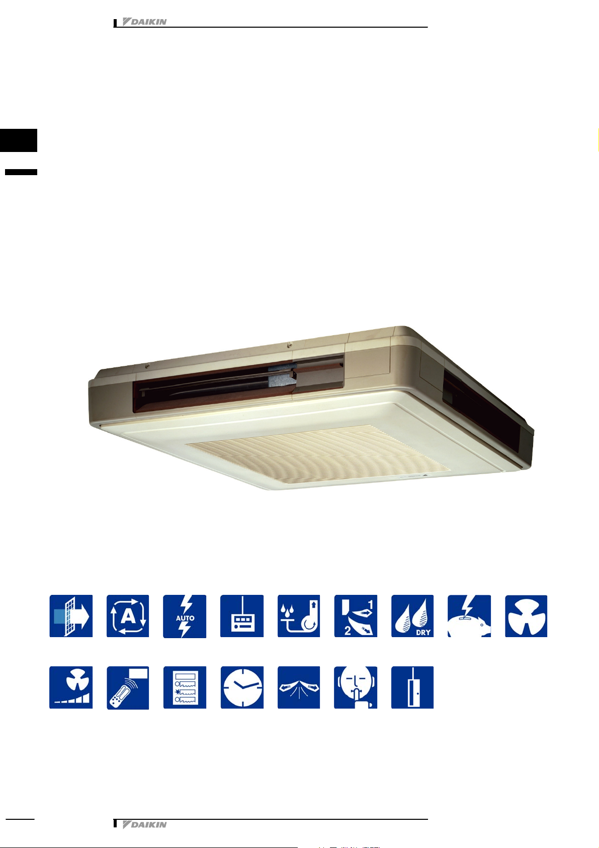
FUQ-BU
4-way Blow Ceiling
Suspended Cassette
technical data
Split
Sky Air
air conditioning systems
Page 2
• Indoor Units • R-410A • FUQ-BVV1B
1 Features
Indoor Unit Split Sky
FUQ-BVV1B R-410A
• Compact&stylish
• Ideal for shops, restaurants or offices requiring maximum floor space
for furniture, decorations and fittings
• Can be installed in both new and existing buildings.
• Flexible installation: can be installed in the middle of a room or in a
1
1
corner.
• Air can be discharged in any of 4 directions
• Possibility to shut 1 or 2 flaps for easy installation in corners
• Air flow distribution for ceiling heights up to 3.5m without loss of
capacity.
• Air filter, drain pan and heat exchanger fin are mildew proof and antibacterial treated.
• Drain-up pump with 500mm lift fitted as standard
• Extremely quiet in operation
• Easy to install
• Daikin remote controls give you easy control at your fingertips.
• The wired remote control provides you with a schedule timer,
enabling to program the air conditioning daily or weekly.
• The optional remote ON/OFF enables you to start/stop the air
conditioning from a mobile phone via a telephone remote control
(field supply).
• The optional forced OFF enables you to switch off the unit
automatically. E.g. when a window is opened, the unit switches off.
• The ’home leave’ operation button prevents large temperature
differences by continuously operating at a minimum (heating mode)
or maximum (cooling mode) preset level while you’re out or sleeping.
It also allows the indoor temperature to return quickly to your
favourite comfort level.
2 steps
heat pump optional standard
optional
• Split Sky Air • Indoor Units1
optional
Page 3
• Indoor Units • R-410A • FUQ-BVV1B
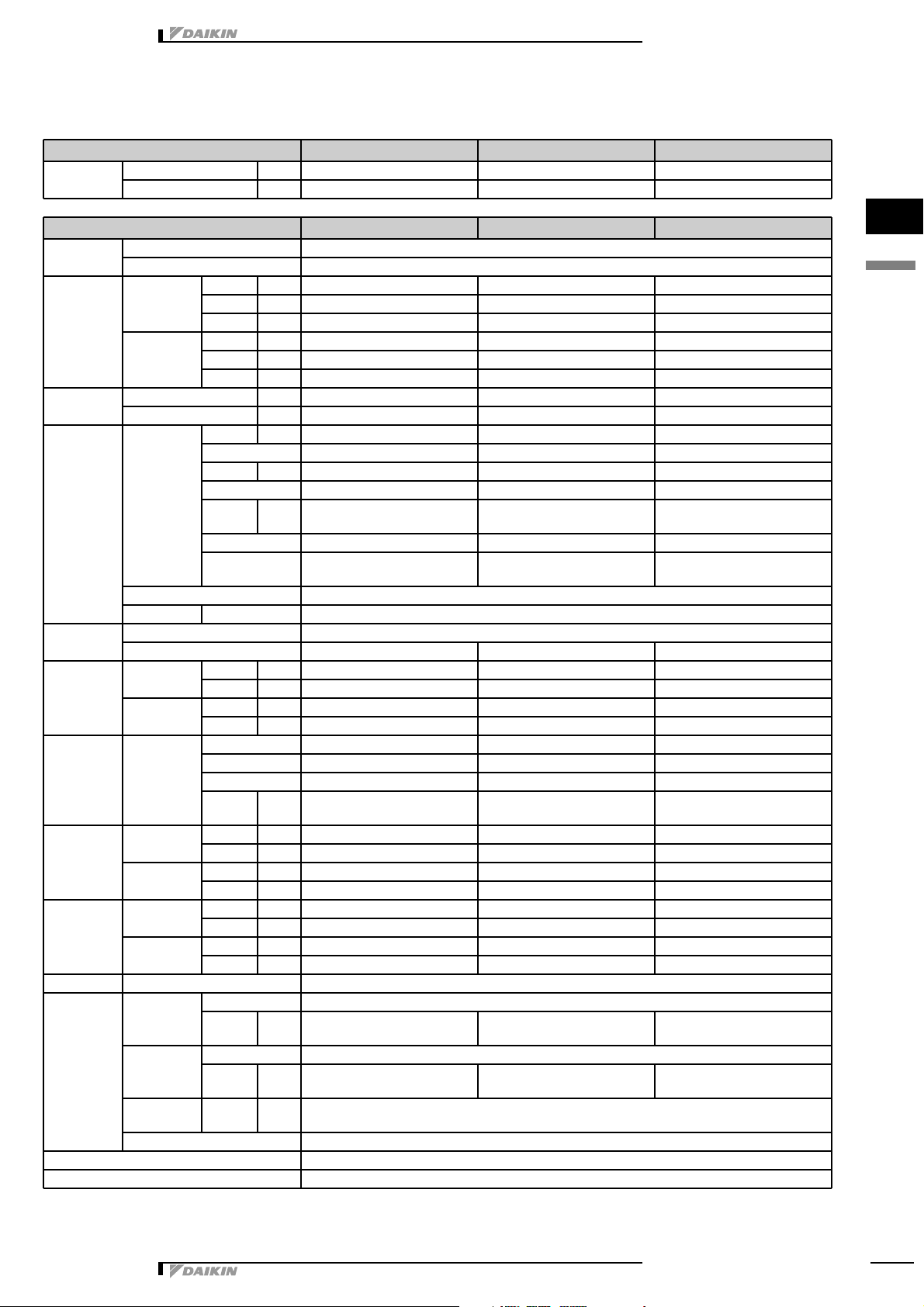
2 Specifications
2-1 FOR INDOOR UNITS ONLY
Nominal Input Cooling kW 0.180 0.289 0.289
Heating kW 0.160 0.269 0.269
2-2 TECHNICAL SPECIFICATIONS
Casing Colour White
Material Resin
Dimensions Packing Height mm 230 295 295
Width mm 960 960 960
Depth mm 960 960 960
Unit Height mm 165 230 230
Width mm 895 895 895
Depth mm 895 895 895
Weight Unit kg 25.0 31.0 31.0
Packed Unit kg 31.0 38.0 38.0
Heat
Exchanger
Fan Type Turbo fan
Air Flow Rate Cooling High m³/min 19.0 29.0 32.0
Fan Motor Quantity 1 1 1
Cooling Sound Power High dBA 56.0 59.0 60.0
Heating Sound Power High dBA 56.0 59.0 60.0
Refrigerant Type R-410A
Piping
connections
Air Filter Resin net with mold resistance
Safety Devices Fan motor thermal protector
Dimensions Length mm 2101 2101 2101
Nr of Rows 3 3 3
Fin Pitch mm 1.50 1.50 1.50
Nr of Passes 8 8 12
Face
Area
Nr of Stages 6 8 8
Empty Tubeplate
Hole
Tube type N-Hix
Fin Type Cross fin coil (Multi louver fins and N-hix tubes)
Quantity 1 1 1
Low m³/min 14.0 21.0 23.0
Heating High m³/min 19.0 29.0 32.0
Low m³/min 14.0 21.0 23.0
Model QTS48A10M QTS50B15M QTS50B15M
Number of steps 2 2 2
Output
(high)
Low dBA 51.0 54.0 55.0
Sound
Pressure
Sound
Pressure
Liquid (OD) Type Flare connection
Gas Type Flare connection
Drain Diameter
Heat Insulation Heat resistant foamed polyethylene, regular foamed polyethylene
High dBA 40.0 43.0 44.0
Low dBA 35.0 38.0 39.0
Low dBA 51.0 54.0 55.0
High dBA 40.0 43.0 44.0
Low dBA 35.0 38.0 39.0
Diameter
(OD)
Diameter
(OD)
(OD)
m² 0.265 0.353 0.353
W 45 90 90
mm 9.5 9.5 9.5
mm 15.9 15.9 15.9
mm I.D. 20/O.D. 26
FUQ71BVV1B FUQ1 00BVV1B FUQ125BVV1B
FUQ71BVV1B FUQ1 00BVV1B FUQ125BVV1B
4
3
1
2
• Split Sky Air • Indoor Units 2
Page 4
• Indoor Units • R-410A • FUQ-BVV1B
2 Specifications
1
2
2-2 TECHNICAL SPECIFICATIONS
Standard
Accessories
Item Installation and operation manual
Quantity 1 1 1
Item Drain hose
2-3 ELECTRICAL SPECIFICATIONS
Power Supply Name V1
Phase 1 1 1
Frequency Hz 50 50 50
Voltage V 220-240
Power Supply Intake Outdoor unit only
FUQ7 1BVV1B FUQ100BVV1B F UQ125BVV1B
Clamp metal
Insulation for fitting
Sealing pad
Clamps
Screws
Washer
Joint
Holding plate
FUQ7 1BVV1B FUQ100BVV1B F UQ125BVV1B
• Split Sky Air • Indoor Units3
Page 5
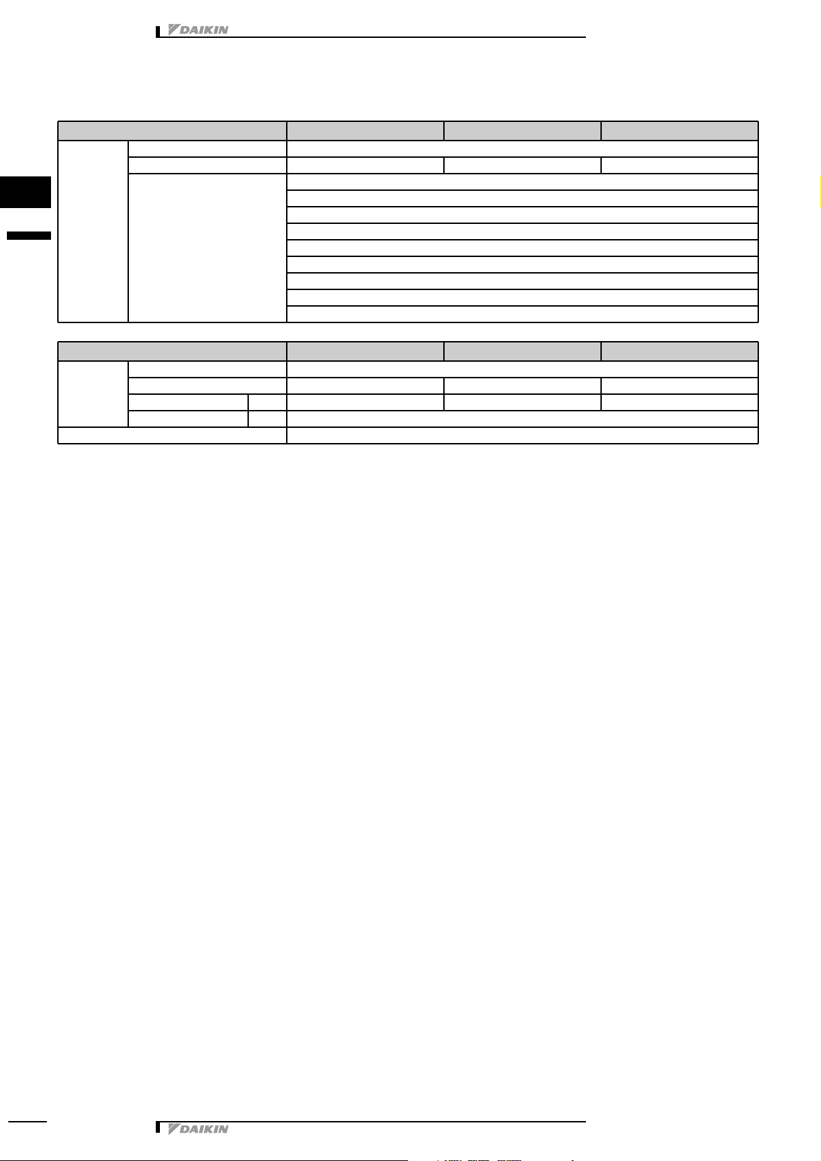
• Indoor Units • R-410A • FUQ-BVV1B
FUQ71-100-125B
Model Safety devices FUQ71BUV1B FUQ100BUV1B FUQ125BUV1B
FUQ-B
Fuse − − −
Fan motor thermal fuse (°C) − − −
Fan motor thermal protector (°C) Off: 130±5 Off: 130±5 Off: 130±5
4D013856
E
3 Safety device settings
3
1
3
• Split Sky Air • Indoor Units 4
Page 6
• Indoor Units • R-410A • FUQ-BVV1B
Name of option Remark
FUQ∼B
71 100 125
Sealing member of air discharge outlet KDBH49FA80 KDBH49FA140
Decoration panel for air discharge KDBT49FA80 KDBT49FA140
Vertical flap kit KDGJ49FA80 KDGJ49FA140
Replacement long-life filter KAF495FA140
L connection piping kit KHFP49MA140
Remote control Wired type BRC1D528
Infrared type Heat pump BRC7CA528W
Cooling only BRC7CA529W
Central remote control DCS302CA51
Unified ON/OFF control DCS301BA51
Schedule timer DST301BA51
Wiring adapter for electrical appendices KRP4AA53 *1
Interface adapter for Sky Air series DTA112BA51
Installation box for adapter PCB KRP1BA97
Remote sensor KRCS01-1A
Connector for forced on, forced off EKROROA
Electrical box with earth terminal (3 blocks) KJB311AA
Electrical box with earth terminal (2 blocks) KJB212AA
3D044484A
NOTE: *1: Installation box for adapter PCB (KRP1BA97) is necessary
4 Options
1
4
• Split Sky Air • Indoor Units5
Page 7

• Indoor Units • R-410A • FUQ-BVV1B
3TW23651-2
6.5 x 9 (Round end slit)
Cover open
Cover closed
5 x 7 (Round end slit)
HoleJ5
5 x 10 (Round end slit)
BRC1D52
5 Control systems
3
1
5
• Split Sky Air • Indoor Units 6
Page 8

• Indoor Units • R-410A • FUQ-BVV1B
3D013860D
FUQ71B
1
Liquid pipe connection - J9.5 flare
2 Gas pipe connection J15.9 flare
3 Drain pipe connection V.P.20
4 Air outlet
5 Air suction grille
6 Corner decoration cover
7 Right pipe / wiring connection
8 Rear pipe / wiring connection
9 Pipe through cover
10 Accessory drain elbow
790 (Suspension position)
Note:
1. Location for manufacture’s label: on bell mouth.
2. This is where the signal of infrared remote control
is received. Refer to the drawing of infrared
remote control in detail.
3. When closing the discharge grill (2 or 3 way
discharge), direction of pipe connection will be
limited, please refer to installation manual.
unit (mm)
z 1500 mm or
more
z 1500 mm or
more
z 1500 mm or more
z 1500 mm
or more
Required space
z When closing the discharge grill, the required space is
30mm or more. (Note 3)
790
Suspension position
Suspension bolt
Height of suspension bracket
1000mm or more
(required space)
Drain connection
location for rear piping
Drain connection
location for upper
piping
z
Drain pipe can be raised up to 350mm from the top surface of the product.
Brand name plate (note 2)
FUQ100-125B
1
Liquid pipe connection - J9.5 flare
2 Gas pipe connection J15.9 flare
3 Drain pipe connection V.P.20
4 Air outlet
5 Air suction grille
6 Corner decoration cover
7 Right pipe / wiring connection
8 Rear pipe / wiring connection
9 Pipe through cover
10 Accessory drain elbow
790 (Suspension position)
Note:
1. Location for manufacture’s label: on bell mouth.
2. This is where the signal of infrared remote control
is received. Refer to the drawing of infrared
remote control in detail.
3. When closing the discharge grill (2 or 3 way
discharge), direction of pipe connection will be
limited, please refer to installation manual.
unit (mm)
z 1500 mm or
more
z 1500 mm or
more
z 1500 mm or more
z 1500 mm
or more
3D044898
B
Required space
z When closing the discharge grill, the required space is
30mm or more. (Note 3)
790
Suspension position
Suspension bolt
Height of suspension bracket
1000mm or more
(required space)
Drain connection
location for rear
piping
Drain connection
location for upper
piping
z
Drain pipe can be raised up to 350mm from the top surface of the product.
Brand name plate (note 2)
6 Dimensional drawing & centre of gravity
6 - 1 Dimensional drawing
1
6
• Split Sky Air • Indoor Units7
Page 9

• Indoor Units • R-410A • FUQ-BVV1B
4D037995
F
O
Check valve
L
Flare connection
M
Screw connection
N
Flange connection Z Pinched pipePSpinned pipe
Indoor heat exchanger
Field piping JA C1220T-0
FUQ71-100-125B
Field piping JB C1220T-0
Refrigerant pipe connection port diameters
Model A B
FUQ71, 100, 125B J9.5 J15.9
To outdoor unit
Indoor unit
7 Piping diagram
3
1
7
• Split Sky Air • Indoor Units 8
Page 10

8 Wiring diagram
3D043746
A
FUQ71∼125B
A1P Printed circuit board
C1R Capacitor (M1F)
HAP Light emitting diode (service monitor green)
KAR Magnetic relay (M1S)
KPR Magnetic relay ((M1P)
M1F Motor (indoor fan)
M1P Motor (drain pump)
M1S Motor (swing flap)
Q1M Thermo switch (M1F embedded)
R1T Thermistor (air)
R2T Thermistor (coil)
S1L Float switch (M1A)
S1Q Limit switch (swing flap)
SS1 Selector switch (emergency)
T1R Transformer (220-240V/22V)
V1TR Phase control circuit
X1M Terminal strip
X2M Terminal strip
? Signal receiver circuit
. Signal transmission circuit
Wired remote control
R1T Thermistor (air)
SS1 Selector switch (main/sub)
Receiver / display unit (attached to infrared remote controller)
A2P Printed circuit board
A3P Printed circuit board
BS1 Push button (on/off)
H1P Light emitting diode (service monitor red)
H2P Light emitting diode (service monitor green)
H3P Light emitting diode (service monitor red)
H4P Light emitting diode (service monitor orange)
SS1 Selector switch (main/sub)
SS2 Selector switch (wireless address set)
Connector for optional parts
X35A Connector (group control adapter)
X60A
X61A
Connector (interface adapter for sky air series)
To outdoor
unit
Note) 4
Wired remote
control
Control box
In case of simultaneous
operation system.
To outdoor unit
Notes
1. D : Terminal F : Connector
b : Protective earth (screw)
2.
: Field wiring
3. In case using central remote control, connect it to the unit in
accordance with the attached instruction manual.
4. X24A is connected when the infrared remote control kit is
being used.
5. Remote control model varies according to the combination
system, confirm technical materials and catalogs, etc. before
connecting.
6. Symbols show as follows Red:red, Blk:black, Ylw:yellow,
Org:orange, Gry:gray, Prp:purple, Blu:blue
7. Confirm the method of setting the selector switch (SS1, SS2)
by installation manual and engeneering materials, etc.
Receiver / display unit
Note) 4
Indoor unit
(master)
Indoor unit
(slave)
Infrared remote
control
Norm.
Emerg.
8 - 1 Wiring diagram
1
8
• Indoor Units • R-410A • FUQ-BVV1B
• Split Sky Air • Indoor Units9
Page 11

• Indoor Units • R-410A • FUQ-BVV1B
4D013833C
V1, Model
Power supply
1∼50Hz
220V-240V
Fuse
Main switch
Main switch
Fuse
Fuse
NOTES
1
Line voltage wiring
Control circuit wiring
2 All wiring, components and materials to be produced on the site must comply with the applicable local and national codes.
3 Use copper conductors only.
4 See wiring diagrams for details.
5 Install fuse and mainswitch for safety.
6 All field wiring and components must be provided by a licensed electrician.
7 The unit shall be grounded in compilance with the applicable local and national codes.
8 Wiring shown are general points-of-connection guides only and are not intended for or to include all details for a specific
installation.
9 Never share a common power supply with other equipment.
Y1, Model
Power supply
3N∼50Hz
400V
V3, Model
Power supply
1∼50Hz
230V
Main switch
FUQ71∼125B
8 Wiring diagram
8 - 2 External connection diagram
3
1
8
• Split Sky Air • Indoor Units 10
Page 12

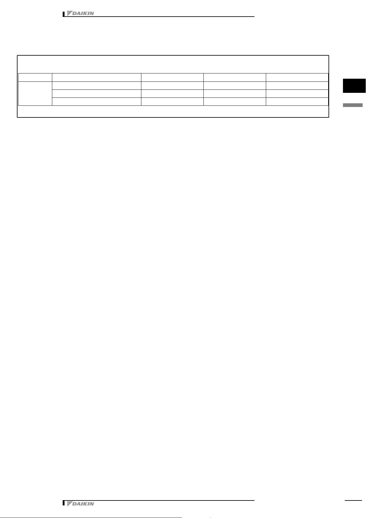
9 Sound data
Location of
microphone
Model
Sound pressure level
Sound power level230V
50Hz
Cooling
(H/L)
Heating
(H/L)
Measuring location Cooling
(H/L)
Heating
(H/L)
FUQ71B 40/35 40/35 56/51 56/51
FUQ100B 43/38 43/38 59/54 59/54
FUQ125B 44/39 44/39 60/55 60/55
9 - 1 Sound level data
1
9
• Indoor Units • R-410A • FUQ-BVV1B
• Split Sky Air • Indoor Units11
Page 13

• Indoor Units • R-410A • FUQ-BVV1B
4D014037
D
Octave band sound pressure level
Octave band center frequency (Hz)
FUQ71B
approximate
threshold hearing
for continuous
noise
NOTES
1 Sound pressure levels are measured in an anechoic
room.
2 Operation sound levels are valid at nominal
operation condition
3 Operation sound level differs with operation and
ambient conditions.
H (230V)
L (230V)
4D014038
D
Octave band sound pressure level
Octave band center frequency (Hz)
FUQ100B
approximate
threshold hearing
for continuous
noise
NOTES
1 Sound pressure levels are measured in an anechoic
room.
2 Operation sound levels are valid at nominal
operation condition
3 Operation sound level differs with operation and
ambient conditions.
H (230V)
L (230V)
4D014039
D
FUQ125B
Octave band sound pressure level
Octave band center frequency (Hz)
NOTES
1 Sound pressure levels are measured in an anechoic
room.
2 Operation sound levels are valid at nominal
operation condition
3 Operation sound level differs with operation and
ambient conditions.
approximate
threshold hearing
for continuous
noise
H (230V)
L (230V)
9 Sound data
9 - 2 Sound pressure spectrum
3
1
9
• Split Sky Air • Indoor Units 12
Page 14

10 Air flow pattern
4D028396C
FUQ71B
Cooling - air velocity distribution
4-way discharge air flow direction: horizontal
FUQ71B
Cooling - air temperature distribution
4-way discharge air flow direction: horizontal
1
10
• Indoor Units • R-410A • FUQ-BVV1B
• Split Sky Air • Indoor Units13
Page 15

10 Air flow pattern
4D028397C
FUQ100B
Cooling - air velocity distribution
4-way discharge air flow direction: horizontal
FUQ100B
Cooling - air temperature distribution
4-way discharge air flow direction: horizontal
• Indoor Units • R-410A • FUQ-BVV1B
3
1
10
• Split Sky Air • Indoor Units 14
Page 16

10 Air flow pattern
4D028398C
FUQ125B
Cooling - air velocity distribution
4-way discharge air flow direction: horizontal
FUQ125B
Cooling - air temperature distribution
4-way discharge air flow direction: horizontal
1
10
• Indoor Units • R-410A • FUQ-BVV1B
• Split Sky Air • Indoor Units15
Page 17

10 Air flow pattern
4D013863
D
FUQ71B
Heating - air velocity distribution
4-way discharge, air flow direction: down
FUQ71B
Heating - air temperature distribution
4-way discharge, air flow direction: down
• Indoor Units • R-410A • FUQ-BVV1B
3
1
10
• Split Sky Air • Indoor Units 16
Page 18

10 Air flow pattern
4D014054
D
FUQ100B
Heating - air velocity distribution
4-way discharge, air flow direction: down
FUQ100B
Heating - air temperature distribution
4-way discharge, air flow direction: down
1
10
• Indoor Units • R-410A • FUQ-BVV1B
• Split Sky Air • Indoor Units17
Page 19

10 Air flow pattern
4D014055
D
FUQ125B
Heating - air velocity distribution
4-way discharge, air flow direction: down
FUQ125B
Heating - air temperature distribution
4-way discharge, air flow direction: down
• Indoor Units • R-410A • FUQ-BVV1B
3
1
10
• Split Sky Air • Indoor Units 18
Page 20

11 Installation
Names and functions of parts
j
a
Indoor unit
j
b
Outdoor unit
j
c
Infrared remote control
j
d
Inlet air
j
e
Discharged air
j
f
Air outlet
j
g
Air flow flap (at air outlet)
j
h
Refrigerant piping, connection electric wire
j
i
Drain pipe
j
j
Air inlet
The built-in air filter removes dust and dirt.
j
k
Ground wire
Wire to ground from the outdoor unit to prevent electrical
shocks.
j
l
Drain pumping out device (built-in)
Drains water removed from the room during cooling
11 - 1 Installation method
1
11
• Indoor Units • R-410A • FUQ-BVV1B
• Split Sky Air • Indoor Units19
 Loading...