

Daikin FTXS09DVJU, FTXS12DVJU, FTXS24DVJU, RX09FVJU, RX12FVJU Service Manual
...
SiUS04 - 702
Inverter Pair
Wall Mounted Type D-Series
[Applied Models]
z Inverter Pair : Heat Pump

SiUS04-702
z
Heat Pump
Indoor Unit
FTXS09DVJU
FTXS12DVJU
FTXS15DVJU
FTXS18DVJU
FTXS24DVJU
Outdoor Unit
Inverter Pair
D-Series
RX09FVJU
RX12FVJU
RX15FVJU
RX18FVJU
RX24FVJU
Table of Contents i

SiUS04-702
1. Introduction ............................................................................................... vi
1.1 Safety Cautions...........................................................................................vi
1.2 Used Icons ...................................................................................................x
Part 1 List of Functions ...................................................................1
1. List of Functions.........................................................................................2
Part 2 Specifications .......................................................................3
1. Specifications.............................................................................................4
Part 3 Printed Circuit Board Connector Wiring Diagram ................7
1. Printed Circuit Board Connector Wiring Diagram.......................................8
1.1 FTXS09/12DVJU......................................................................................... 8
1.2 FTXS15/18/24DVJU.................................................................................. 10
1.3 RX09/12FVJU ........................................................................................... 12
1.4 RX15/18/24FVJU ...................................................................................... 14
Part 4 Function and Control...........................................................17
1. Main Functions.........................................................................................19
1.1 Frequency Principle................................................................................... 19
1.2 Power-Airflow Dual Flaps, Wide-Angle Louvres and Auto-Swing ............. 21
1.3 Fan Speed Control for Indoor Units........................................................... 22
1.4 Programme Dry Function ............................... ............... ................ ............ 23
1.5 Automatic Operation.............................. ............... ................ ............... ...... 24
1.6 Thermostat Control.................................................................................... 25
1.7 NIGHT SET Mode ..................................................................................... 26
1.8 INTELLIGENT EYE............... .................................................................... 27
1.9 HOME LEAVE Operation .......................................................................... 29
1.10 Inverter POWERFUL Operation...................................... ................ .......... 30
1.11 Other Functions................... ................ ............... ................ ............... ........ 31
2. Function of Thermistor.............................................................................33
2.1 Heat Pump Model..... ................ ............... ................ ............... ............... .... 3 3
3. Control Specification (09/12 Class)..........................................................34
3.1 Mode Hierarchy............... .......................................................................... 34
3.2 Frequency Control..................................................................................... 35
3.3 Controls at Mode Changing / Start-up....................................................... 37
3.4 Discharge Pipe Temperature Control................................... ............... ...... 38
3.5 Input Current Control................................................................................. 39
3.6 Freeze-up Protection Control .............. ............... ................ ............... ........ 39
3.7 Heating Peak-cut Control .......................................................................... 40
3.8 Fan Control................................................................................................ 40
3.9 Liquid Compression Protection Function 2 ................ ............................... . 40
3.10 Defrost Control ............................... ................ ............... ................ ............ 41
3.11 Electronic Expansion Valve Control .......................................................... 42
3.12 Malfunctions .............................................................................................. 45
3.13 Forced Operation Mode ............................................................................ 46
ii Table of Contents

SiUS04-702
3.14 Additional Function... ................ ............... ................ ............... ................... 46
4. Control Specification (15/18/24 Class).....................................................47
4.1 Mode Hierarchy............... .......................................................................... 47
4.2 Frequency Control..................................................................................... 48
4.3 Controls at Mode Changing / Start-up....................................................... 50
4.4 Discharge Pipe Temperature Control................................... ............... ...... 51
4.5 Input Current Control................................................................................. 52
4.6 Freeze-up Protection Control .............. ............... ................ ............... ........ 53
4.7 Heating Peak-cut Control .......................................................................... 53
4.8 Fan Control................................................................................................ 54
4.9 Liquid Compression Protection Function 2 ................ ............................... . 54
4.10 Low Hz High Pressure Limit................ ............... ................ ............... ........ 55
4.11 Defrost Control ............................... ................ ............... ................ ............ 55
4.12 Electronic Expansion Valve Control .......................................................... 56
4.13 Malfunctions .............................................................................................. 59
4.14 Forced Operation Mode ............................................................................ 60
4.15 Additional Function... ................ ............... ................ ............... ................... 60
Part 5 Operation Manual ................................................................61
1. System Configuration...............................................................................62
2. Instruction.................................................................................................63
2.1 Safety Precautions .................................................................................... 63
2.2 FTXS09/12DVJU....................................................................................... 65
2.3 FTXS15/18/24DVJU.................................................................................. 90
Part 6 Service Diagnosis..............................................................115
1. Caution for Diagnosis.............................................................................116
2. Problem Symptoms and Measures........................................................118
3. Service Check Function.........................................................................119
4. Troubleshooting .....................................................................................122
4.1 Error Codes and Description................................................................... 122
4.2 Indoor Unit PCB Abnormality .................................................................. 123
4.3 Freeze-up Protection Control or High Pressure Control............. ............. 124
4.4 Fan Motor or Related Abnormality ...... ............... ................ ............... ...... 126
4.5 Thermistor or Related Abnormality (Indoor Unit)..................................... 129
4.6 Signal Transmission Error (between Indoor and Outdoor Unit) .............. 130
4.7 OL Activation (Compressor Overload) ............................ .................. ...... 132
4.8 Compressor Lock .................................................................................... 133
4.9 DC Fan Lock ............ ................ ............... ................ ............... ............... .. 135
4.10 Input Over Current Detection .................................................................. 136
4.11 Four Way Valve Abnormality................... ................................................ 139
4.12 Discharge Pipe Temperature Control.... ............................... ............... .... 143
4.13 High Pressure Control in Cooling............................................................ 145
4.14 Position Sensor Abnormality ................................................................... 149
4.15 DC Voltage / Current Sensor Abnormality ............... ............... ................. 151
4.16 CT or Related Abnormality...................................................................... 152
4.17 Thermistor or Related Abnormality (Outdoor Unit).. .. .............................. 154
Table of Contents iii

SiUS04-702
4.18 Electrical Box Temperature Rise............................... ............... ............... 156
4.19 Radiation Fin Temperature Rise ............................................................. 158
4.20 Output Over Current Detection................................................................ 160
4.21 Insufficient Gas........................................................................................ 164
4.22 Over-voltage Detection............................ ................ .............................. .. 168
4.23 Low-voltage Detection............................................................................. 169
5. Check.....................................................................................................170
5.1 How to Check.......................................................................................... 170
Part 7 Removal Procedure ...........................................................181
1. FTXS09/12DVJU....................................................................................182
1.1 Removal of Air Filter.................................. ................ ............... ............... 182
1.2 Removal of Front Grille .................................. ............... .......................... 185
1.3 Removal of Horizontal Blade and Vertical Blade................................... .. 188
1.4 Removal of Electrical Box, PCB and Swing Motor.................................. 190
1.5 Removal of Heat Exchanger ............... ............... ............................... ...... 196
1.6 Install of Drain Plug .. ................ ............................... ............... ............... .. 199
1.7 Removal of Fan Rotor and Fan Motor......................... ............... ............. 201
2. FTXS15/18/24DVJU...............................................................................205
2.1 Removal of the Air Filter / Front Panel .... ............................... ............... .. 205
2.2 Removal of the Front Grille ....................... ................ ............... ............... 209
2.3 Removal of the Horizontal Blades / Vertical Blades................... ............. 212
2.4 Removal of the Electrical Box / PCB / Swing Motor................................ 215
2.5 Removal of the Heat Exchanger .......................... ................ ............... .... 223
2.6 Removal of the Fan Rotor / Fan Motor........ ................ ............... ............. 226
3. RX09/12FVJU........................................................................................229
3.1 Removal of Panels and Fan Motor.......................... ............... ............... .. 229
3.2 Removal of Electrical Box ................... ............... ............................... ...... 237
3.3 Removal of Reactor and Partition Plate ............................... ............... .... 239
3.4 Removal of Sound Blanket...................................... ............... ............... .. 241
3.5 Removal of Four Way Valve.. ................ ............................... ............... .... 244
3.6 Removal of Compressor.. ............................... ............... ................ .......... 246
3.7 Removal of PCB.................... ................ ............... ................ ............... .... 249
4. RX15/18/24FVJU...................................................................................252
4.1 Removal of the Panels and Plates............................................. ............. 252
4.2 Removal of the Fan Motor / Propeller Fan........................... ................. .. 257
4.3 Removal of the PCB / Electrical Box............................... ................ ........ 261
4.4 Removal of the Reactor... ............... ............................... ................ .......... 270
4.5 Removal of the Sound Blanket........................................ ................ ........ 272
4.6 Removal of the Four Way Valve.................. ................ ............... ............. 275
4.7 Removal of the Electronic Expansion Valve.................. .................. ........ 276
4.8 Removal of the Compressor.. ................ ............................... ............... .... 277
Part 8 Others ................................................................................279
1. Others ....................................................................................................280
1.1 Test Run from the Remote Controller ..................................................... 280
1.2 Jumper Settings ....... ................ ............................... ............... ............... .. 281
iv Table of Contents

SiUS04-702
Part 9 Appendix............................................................................283
1. Piping Diagrams................................. ..... .... .......................................... .284
1.1 Indoor Units............................................................................................. 284
1.2 Outdoor Units .......................................................................................... 285
2. Wiring Diagrams.....................................................................................287
2.1 Indoor Units............................................................................................. 287
2.2 Outdoor Units .......................................................................................... 288
Index ................................................................................................i
Drawings & Flow Charts .................................................................vii
Table of Contents v
Introduction SiUS04-702
1. Introduction
1.1 Safety Cautions
Cautions and
Warnings
Be sure to read the following safety cautions before conducting repair work.
The caution items are classified into “ Warning” and “ Caution”. The “ Warning”
items are especially important since they can lead to death or serious injury if they are not
followed closely. The “ Caution” items can also lead to serious accidents under some
conditions if they are not followed. Therefore, be sure to observe all the safety caution items
described below.
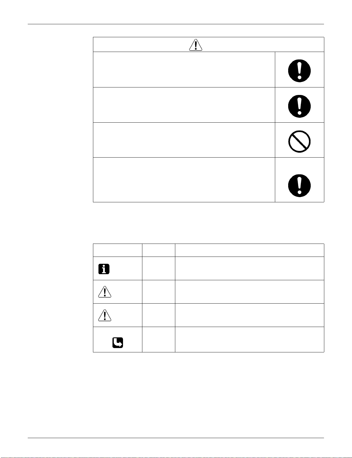
About the pictograms
This symbol indicates the item for which caution must be exercised.
The pictogram shows the item to which attention must be paid.
This symbol indicates the prohibited action.
The prohibited item or action is shown in the illustration or near the symbol.
This symbol indicates the action that must be taken, or the instruction.
The instruction is shown in the illustration or near the symbol.
After the repair work is complete, be sure to conduct a test operation to ensure that the
equipment operates normally, and explain the cautions for operating the product to the
customer.
1.1.1 Cautions Regarding Safety of Workers
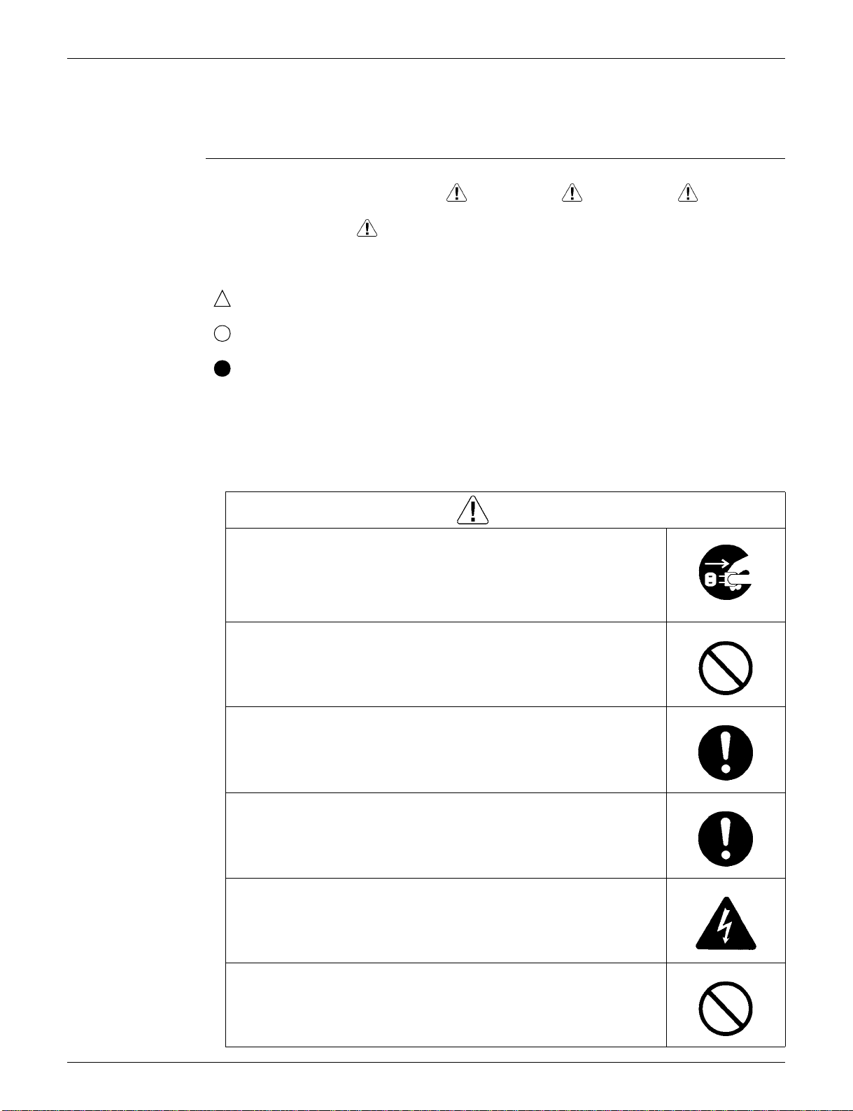
Be sure to disconnect the power cable plug from the plug socket before
disassembling the equipment for repair.
Working on the equipm ent that is conn ected to the powe r supply may ca use an
electrical shook.
If it is necessary to supply power to the equipment to conduct the repair or
inspecting the circuits, do not touch any electrically charged sections of the
equipment.
If the refrigerant gas is discharged during the repair work, do not touch the
discharged refrigerant gas.
The refrigerant gas may cause frostbite.
When disconnecting the suction or discharge pipe of the compressor at the
welded section, evacuate the refrigerant gas completely at a well-ventilated
place first.
If there is a gas remaining inside the compressor, the refrigerant gas or
refrigerating machine oil discharge s when the pipe is di sconnected, and it may
cause injury.
If the refrigerant gas leaks during the repair work, ventilate the area. The
refrigerant gas may generate toxic gases when it contacts flames.
Warning
The step-up capacitor supplies high-voltage electricity to the electrical
components of the outdoor unit.
Be sure to discharge the capacitor completely before conducting repair work.
A charged capacitor may cause an electrical shock.
Do not start or stop the air c onditione r operation b y pluggin g or unplugg ing the
power cable plug.
Plugging or unplugging the power cable plug to operate the equipment may
cause an electrical shock or fire.
vi
SiUS04-702 Introduction
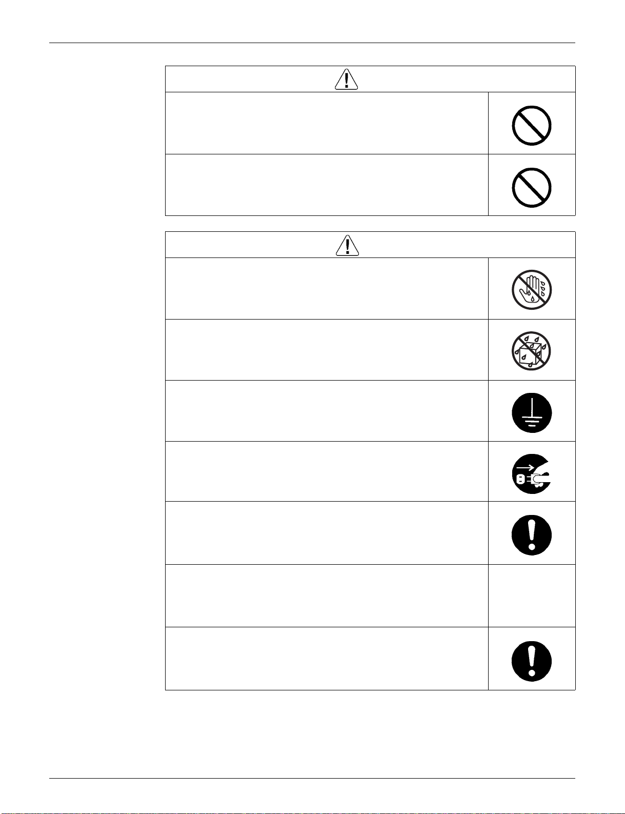
Warning
Be sure to wear a safety helmet, gloves, and a safety belt when working at a
high place (more than 2m). Insufficient safety measures may cause a fall
accident.
In case of R410A refrigerant mode ls, be sure to u se pipes, fl are nuts and to ols
for the exclusive use of the R410A refrigerant.
The use of material s for R22 refrigera nt mod els m ay ca use a seriou s accid ent
such as a damage of refrigerant cycle as well as an equipment failure.
Caution
Do not repair the electrical components with wet hands.
Working on the equipment with wet hands may cause an electrical shock.
Do not clean the air conditioner by splashing water.
Washing the unit with water may cause an electrical shock.
Be sure to provide the grounding when repairing the equipment in a humid or
wet place, to avoid electrical shocks.
Be sure to turn off the power switch and unplug the pow er cable when cleaning
the equipment.
The internal fan rotates at a high speed, and cause injury.
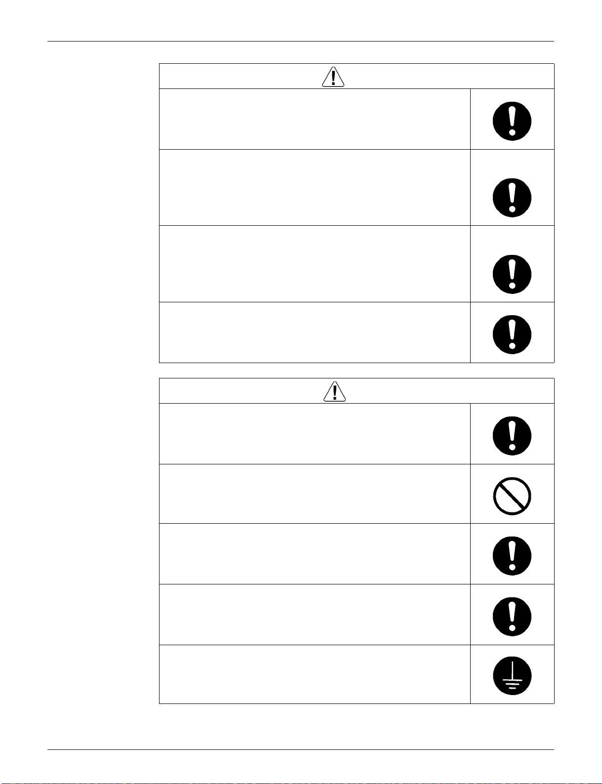
Be sure to conduct repair work with appropriate tools.
The use of inappropriate tools may cause injury.
Be sure to check that the refrigerating cycle section has cooled down enough
before conducting repair work.
Working on the unit when the refrigerating cycle section is hot may cause
burns.
Use the welder in a well-ventilated place.
Using the welder in an enclosed room may cause oxygen deficiency.
vii

Introduction SiUS04-702
1.1.2 Cautions Regarding Safety of Users
Warning
Be sure to use parts liste d in the serv ic e p arts li st o f the app li cab le m od el and
appropriate tools to conduct repair work. Never attempt to modify the
equipment.
The use of inappropriate parts or tools may cause an electrical shock,
excessive heat generation or fire.
If the power cable and lead wires have scratches or deteriorated, be sure to
replace them.
Damaged cable and wires may cause an electrical shock, excessive heat
generation or fire.
Do not use a joined power cable or extension cable, or share the same power
outlet with other electrical appliances, since it may cause an electrical shock,
excessive heat generation or fire.
Be sure to use an exclusiv e power circuit for the equi pment, and follow the local
technical standards related to the electrical equipment, the internal wiring
regulations, and the instruction manual for installation when conducting
electrical work.
Insufficient power circuit capacity and improper electrical work may cause an
electrical shock or fire.
Be sure to use the specified cable for wiring between the indoor and outdoor
units. Make the con nections securel y and route the c able properly s o that there
is no force pulling the cable at the connection terminals.
Improper connections may cause excessive heat generation or fire.
When wiring between t he indoor and o utdoor units, mak e sure that the term inal
cover does not lift off or dismount because of the cable.
If the cover is no t mounted properly, th e terminal connec tion section may c ause
an electrical shock, excessive heat generation or fire.
Do not damage or modify the power cable.
Damaged or modified power cable may cause an electrical shock or fire.
Placing heavy items on the po wer cable, and heating or pu lling the power cable
may damage the cable.
Do not mix air or gas other than the specifie d refri gera nt (R 410 A / R22) in the
refrigerant system.
If air enters the refrigerating system, an excessively high pressure results,
causing equipment damage and injury.
If the refrigerant gas leaks, be sure to locate the leaking point and repair it
before charging the refrigerant. After chargi ng refrigerant, make s ure that there
is no refrigerant leak.
If the leaking point c annot b e loc ated an d the re pair work mus t be st opped, be
sure to perform pump-down and close the service valve, to prevent the
refrigerant gas from leaking into the room. The refrigerant gas itself is
harmless, but it ma y generate toxic gase s when it conta cts flames, such as fan
and other heaters, stoves and ranges.
When relocating the equipment, make sure that the new installation site has
sufficient strength to withstand the weight of the equipment.
If the installation site does not have sufficient strength and if the installation
work is not conducted securely, the equipment may fall and cause injury.
viii
SiUS04-702 Introduction
Warning
Check to make sure that the power cable plug is not dirty or l oose, then insert
the plug into a power outlet securely.
If the plug has d ust or loose connectio n, it may cau se an elec trical shoc k or fire.
Be sure to install the product correctly by using the provided standard
installation frame.
Incorrect use of the installation frame and improper installation may cause the
equipment to fall, resulting in injury.
Be sure to install the pro duct sec urely in th e inst allati on fram e mou nted o n the
window frame.
If the unit is not securely mounted, it may fall and cause injury.
When replacing the coin battery in the remote controller, be sure to disposed
of the old battery to prevent children from swallowing it.
If a child swallows the coin battery, see a doctor immediately.
Caution
Installation of a leak age breaker is ne cessary in some cases depend ing on the
conditions of the installation site, to prevent electrical shocks.
For unitary type
only
For unitary type
only
Do not install the equipment in a place where there is a possibility of
combustible gas leaks.
If the combustible gas leaks and remains around the unit, it may cause a fire.
Check to see if the parts a nd w ire s ar e mo unted and connected properly, and
if the connections at the soldered or crimped terminals are secure.
Improper installation and connections may cause excessive heat generation,
fire or an electrical shock.
If the installation platform or frame has corroded, replace it.
Corroded installation platform or frame may cause the unit to fall, resulting in
injury.
Check the grounding, and repair it if the equipment is not properly grounded.
Improper grounding may cause an electrical shock.
ix
Introduction SiUS04-702
Caution
Be sure to measure the insulation resistance after the repair, and make sure
that the resistance is 1 MΩ or higher.
Faulty insulation may cause an el ectrical shock.
Be sure to check the drainage of the indoor unit after the repair.
Faulty drainage may cause the water to enter the room and wet the furniture
and floor.
Do not tilt the unit when removing it.
The water inside the unit may spill and wet the furniture and floor.
Be sure to install the packing and seal on the installation frame properly.
If the packing and seal are not insta lled properly, water may en ter the room and
wet the furniture and floor.
1.2 Used Icons
Icons are used to attract the attention of the reader to specific information. The meaning of each
icon is described in the table below:
Icon Type of
Note:
Caution
Warning
For unitary type
only
Description
Information
Note A “note” provides information that is not indisp ensab le, but ma y
nevertheless be valuable to the reader, such as tips and tricks.
Caution A “caution” is used when there is danger tha t the reader, th rough
incorrect manipula tion, may dama ge equipmen t, loose data , get
an unexpected result or has to restart (part of) a procedure.
Warning A “warning” is used when there is danger of personal injury.
Reference A “reference” guides the reader to o ther p lac es in this b ind er or
x
in this manual, where he/ she will find additional in formation on a
specific topic.

SiUS04-702
Part 1
List of Functions
1. List of Functions.........................................................................................2
List of Functions 1
List of Functions SiUS04-702
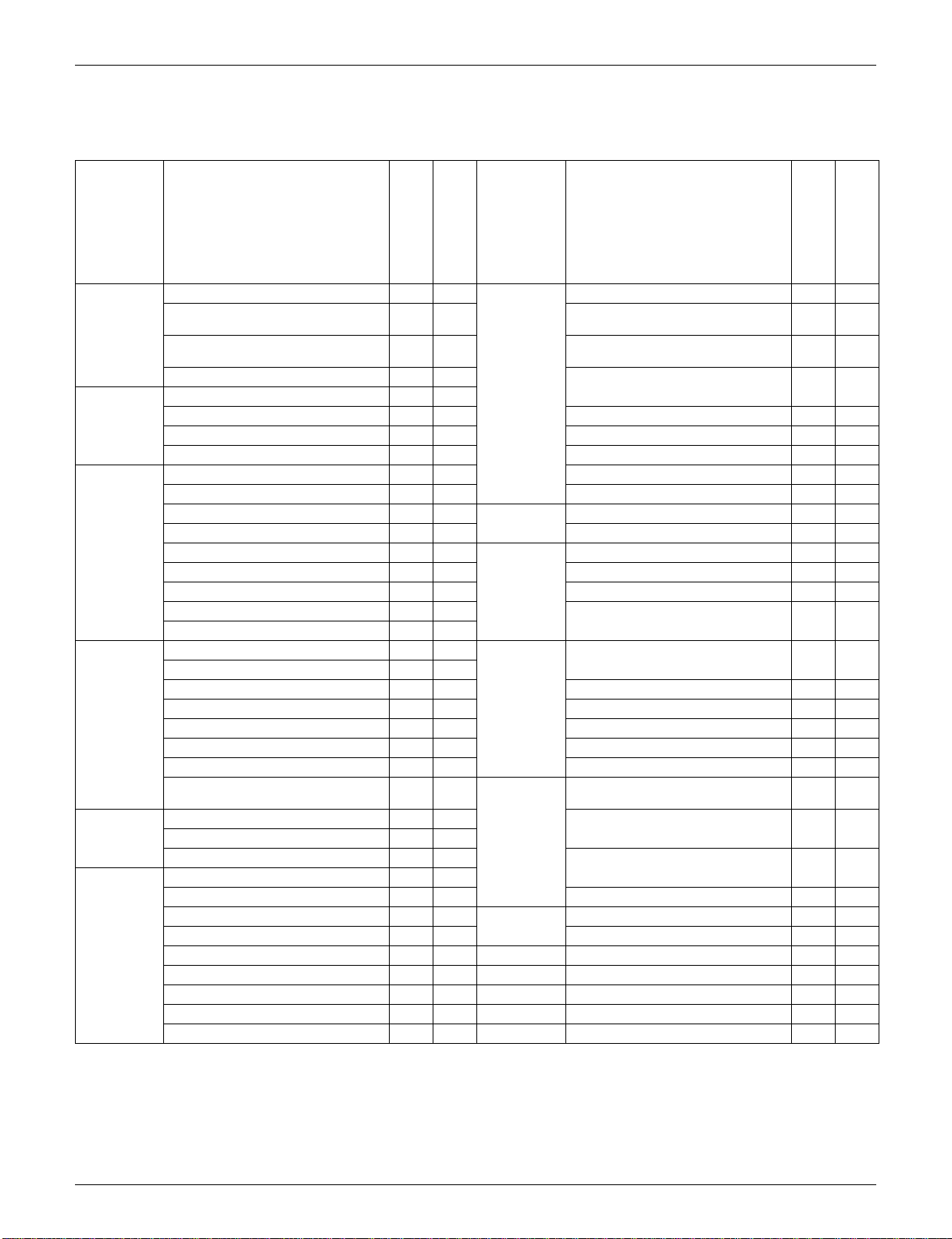
1. List of Functions
Category Functions
FTXS09·12DVJU
RX09·12FVJU
Basic
Function
Compressor Oval Scroll Compressor — —
Comfortable
Airflow
Comfort
Control
Operation Automatic Operation
Lifestyle
Convenience
Inverter (with Inverter Power Control)
Operation Limit for Cooling (°FDB)
Operation Limit for Heating (°FWB)
PAM Control
Swing Compressor
Rotary Compressor — — Wipe-clean Flat Panel
Reluctance DC Motor
Power-Airflow Flap — — Filter Cleaning Indicator — —
Power-Airflow Dual Flaps
Power-Airflow Diffuser — — Timer 24-Hour On/Off Timer
Wide-Angle Louvers
Vertical Auto-Swing (Up and Down)
Horizontal Auto-Swing (Right and Left) —
3-D Airflow —
Comfort Airflow Mode — —
3-Step Airflow (H/P Only) — —
Auto Fan Speed
Indoor Unit Quiet Operation
Night Quiet Mode (Automatic) — — Flexible Voltage Correspondence — —
Outdoor Unit Quiet Operation (Manual)
Intelligent Eye
Quick Warming Function
Hot-Start Function
Automatic Defrosting
Program Dry Function
Fan Only
New Powerful Operation (Non-Inverter) — —
Inverter Powerful Operation
Priority-Room Setting — — Remote
Cooling / Heating Mode Lock — — Wired — —
Home Leave Operation
Indoor Unit On/Off Switch
Signal Reception Indicator
Temperature Display — —
Another Room Operation — —
Note:
: Holding Functions
{
{{
14~
14~
115
115
5~645~
64
{{
{{
{{
{{
{{
{{
{{
{{
{{
{{
{{
{{
{{
{{
{{
{{
{{
{{
{{
{{
— : No Func tions
Category Functions
FTXS15·18·24DVJU
RX15·18·24FVJU
{
{
Health &
Clean
Worry Free
“Reliability &
Durability”
Flexibility
Remote
Control
Controller
Air Purifying Filter — —
Photocatalytic Deodorizing Filter — —
Air Purifying Filter with Photocatalytic
Deodorizing Function
Titanium Apatite Photocatalytic
Air-Purifying Filter
Mold Proof Air Filter
Washable Grille — —
Good-Sleep Cooling Operation — —
Night Set Mode
Auto-Restart (after Power Failure)
Self-Diagnosis (Digital, LED) Display
Wiring Error Check — —
Anticorrosion Treatment of Outdoor
Heat Exchanger
Multi-Split / Split Type Compatible
Indoor Unit
High Ceiling Application — —
Chargeless
Either Side Drain (Right or Left)
Power Selection — —
5-Rooms Centralized Controller
(Option)
Remote Control Adapter
(Normal Open-Pulse Contact) (Option)
Remote Control Adapter
(Normal Open Contact) (Option)
DIII-NET Compatible (Adapter) (Op tion )
Wireless
FTXS09·12DVJU
RX09·12FVJU
FTXS15·18·24DVJU
RX15·18·24FVJU
{{
——
{{
{{
{{
{{
{{
{{
{{
——
33ft 33ft
{{
{{
{{
{{
{{
{{
2 List of Functions

SiUS04-702
Part 2
Specifications
1. Specifications.............................................................................................4
Specifications 3
Specifications SiUS04-702
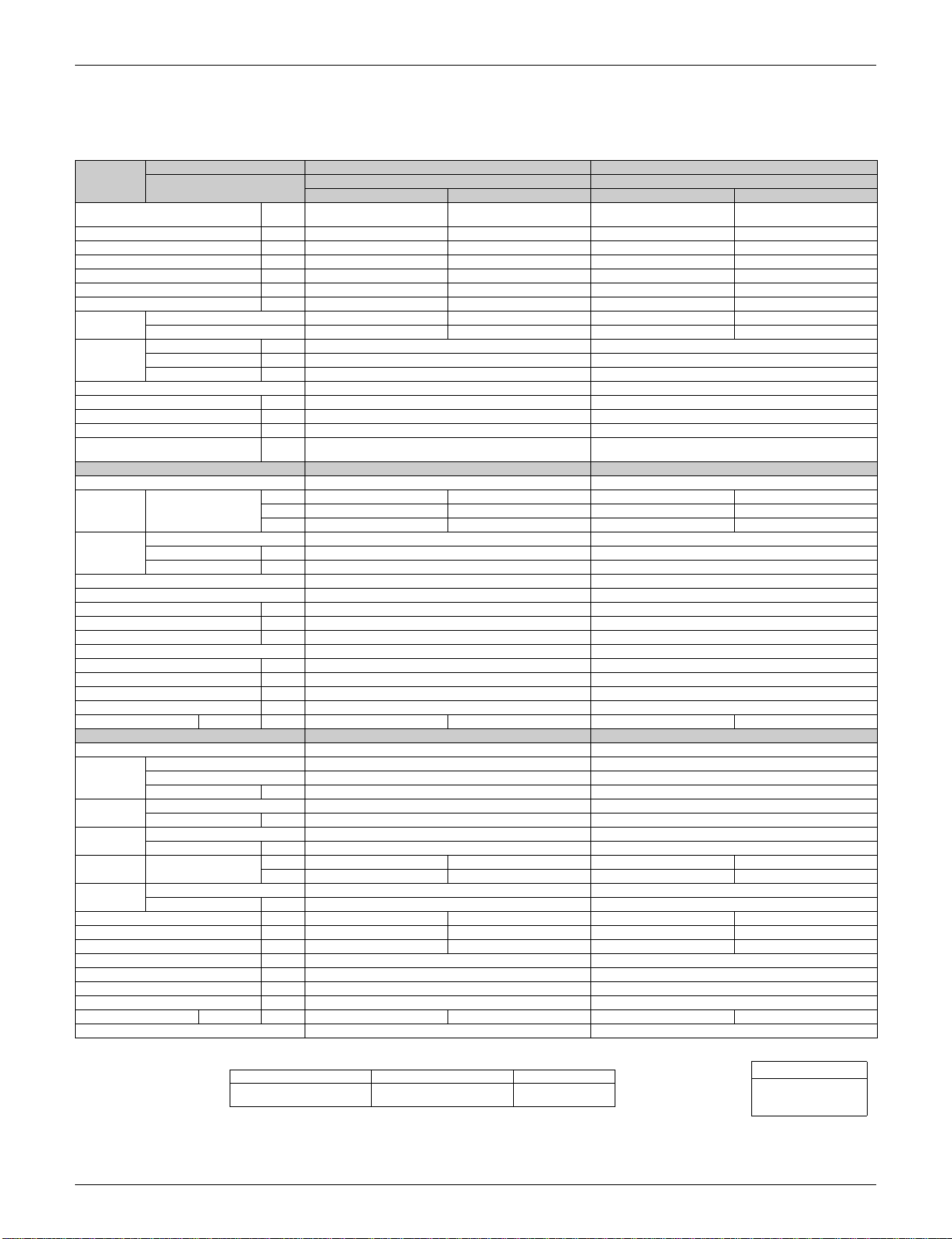
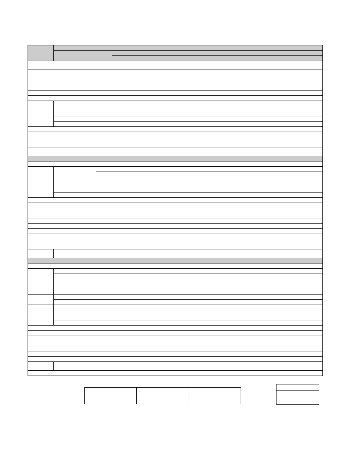
1. Specifications
Hz
60
230V
Models
Capacity
Rated (M in .~Max.)
Moistur e R e moval Pt/h 2.3 — 3.2 —
Running Current (Rated) A 4.56 5.21 6.00 5.20
Power Consumption Rated
Power Factor % 81.1 93.4 97.1 92.0
EER (Rated)
COP (Rated) W/W — 2.62 — 3.06
Energy
Efficiency
Piping
Connections
Heat Insulation Both Liquid and Gas Pipes Both Liquid and Gas Pipes
Max. Interunit Piping Length feet 65 65
Max. Interunit Height Difference feet 49 49
Chargeless feet 33 33
Amount of Additional Charge of
Refrigerant
Indoor Units FTXS09DVJU FTXS12DVJU
Front Panel Color White White
Air Flow Ra te cfm (m³/min)
Fan
Air Direction C o n tro l Right, Left, Horizontal and Downward Right, Left, Horizonta l and Dow nward
Air Filter Removable / Washable / Mildew Proof Removable / Washable / Mildew Proof
Running Current (Rated) A 0.18 0.18
Power Consumption (Rated) W 40 40
Power Factor % 96.6 96.6
Temperature Control Microcomputer Control Microcomputer Control
Dimensions (H×W×D) inch 10-3/4×30-7/8×7-11/16 10-3/4×30-7/8×7-11/16
Packaged Dimensions (H×W×D) inch 10-3/16×32-13/16×12-13/16 10-3/16×32-13/16×12-13/16
Weight Lbs 16.6 16.6
Gross Weight Lbs 25.0 25.0
Operation Sound H/M/L dBA 38 / 32 / 25 38 / 33 / 28 40 / 33 / 26 39 / 34 / 29
Outdoor Units RX09FVJU RX12FVJU
Casing Color Ivory White Ivory White
Compressor
Refrigerant
Oil
Refrigerant
Air Flow Ra te cfm (m³/min)
Fan
Running Current (Rated) A 4.38 5.03 5.87 5.02
Power Consumption (Rated) W 810 1,080 1,310 1,060
Power Factor % 80.4 93.3 97.1 91.8
Dimensions (H×W×D) inch 21-5/8×30-1/8×11-1/4 21-5/8×30-1/8×11-1/4
Packaged Dimensions (H×W×D) inch 25×34-5/8×14-3/16 25×34-5/8×14-3/16
Weight Lbs 74.0 79.0
Gross Weight Lbs 84.0 91.0
Operation Sound H / L dBA 48 / — 49 / — 49 / — 51 / —
Drawing No. 3D056379 3D056380
Indoor Units FTXS09DVJU FTXS12DVJU
Outdoor Units
Btu/h 8,500 (5,100~8,500) 10,000 (5,100~10,000) 11,500 (5,500~11,500) 11,500 (5,500~11,500)
(Min.~Max.)
SEER 13.0 — 13.0 —
HSPF —7.7—7.7
Liquid inch
Gas inch
Drain inch
Type Cross Flow Fan Cross Flow Fan
Motor Ou tp u t W 18 18
Speed Steps 5 Steps, Quiet and Auto 5 Steps, Quiet and Auto
Type Hermetically Sealed Swing Type Hermetically Sealed Swing Type
Model 1YC23NXD 1YC23NXD
Motor Output W 600 600
Type FVC50K FVC50K
Charge oz 12.6 12.6
Type R-410A R-410A
Charge Lbs 1.76 2.20
Type Propeller Propeller
Motor Ou tp u t W 31 31
W 850(300~850) 1,120(290~1,220) 1,350(300~1,350) 1,100(310~1,190)
Btu/h·W
oz/ft 0.22 0.22
H 246(7.0) 253(7.2) 242(6.8) 286(8.1)
M 197(5.6) 220(6.2) 195(5.5) 237(6.7)
L 148(4.2) 187(5.3) 148(4.2) 187(5.3)
H 1,120(31.7) 1,008(28.5) 1,031(29.2) 927(26.3)
L 816(23.1) 813(23.0) 737(20.9) 737(20.9)
Coolin g Heating Cooling Heating
10.0 — 8.5 —
RX09FVJU RX12FVJU
φ
1/4
φ
3/8
φ
11/16
φ
1/4
φ
3/8
φ
11/16
Note:
The data are based on the conditions shown in the table below.
Cooling Heating Piping Length
Indoor ; 80°FDB/67°FWB
Outdoor ; 95°FDB/75°FWB
Indoor ; 70°FDB/60°FWB
Outdoor ; 47°FDB/43°FWB
25ft
Conversion Formulae
kcal/h=kW×860
Btu/h=kW×3414
cfm=m³/min×35.3
4 Specifications
SiUS04-702 Specifications
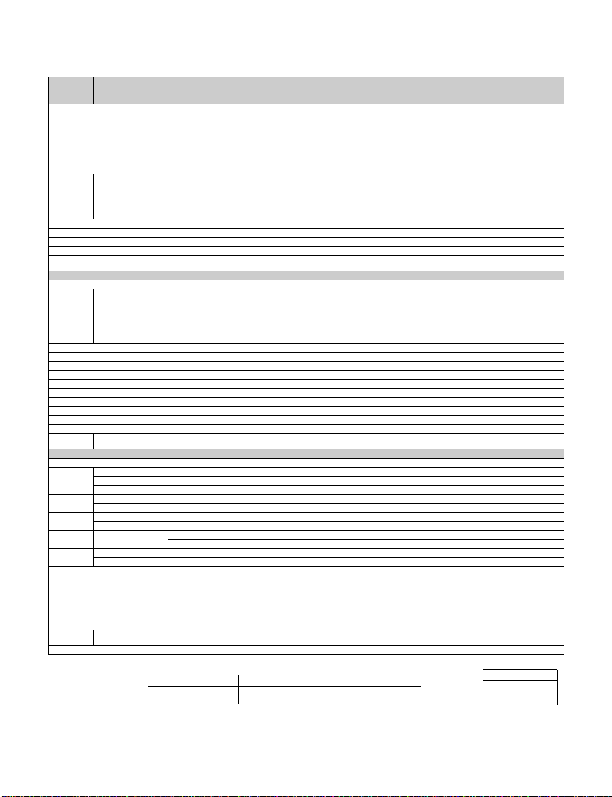
60Hz 230V
Model
Capacity
Rated (M in .~Max.)
Moistur e R e moval Pt/h 3.4 — 4.3 —
Running Current (Rated) A 6.01 7.58 7.67 9.58
Power Consumption Rated
Power Factor % 98.4 99.2 99.2 99.8
EER (Rated)
COP (Rated) W/W — 3.05 — 2.88
Energy
Efficiency
Piping
Connections
Heat Insulation Both Liquid and Gas Pipes Both Liquid and Gas Pipes
Max. Interunit Piping Length feet 98.4 98.4
Max. Interunit Height Difference feet 65.6 65.6
Chargeless feet 33 33
Amount of Additional Charge of
Refrigerant
Indoor Unit FTXS15DVJU FTXS18DVJU
Front Panel Color White White
Air Flow Ra te cfm (m³/min)
Fan
Air Direction C o n tro l Rig h t, Le ft, Horizontal, Do w n ward Right, Left, H o riz o n ta l, D o wnward
Air Filter Removable / Washable / Mildew Proof Removable / Washable / Mildew Proof
Running Current (Rated) A 0.18 0.18
Power Consumption (Rated) W 40 40
Power Factor % 96.6 96.6
Temperature Control Microcomputer Control Microcomputer Control
Dimensions (H×W×D) inch 11-7/16×41-5/16×9-3/8 11-7/16×41-5/16×9-3/8
Packaged Dimensions (H×W×D) inch 13-1/4×45-3/16×14-7/16 13-1/4×45-3/16×14-7/16
Weight Lbs 26.5 26.5
Gross Weight Lbs 38.0 38.0
Operation
Sound
Outdoor Unit RX15FVJU RX18FVJU
Casing Color Ivory White Ivory White
Compressor
Refrigerant
Oil
Refrigerant
Air Flow Ra te cfm (m³/min)
Fan
Running Current (Rated) A 5.83 7.4 7.49 9.40
Power Consumption (Rated) W 1,320 1,690 1,710 2,160
Power Factor % 98.4 99.3 99.3 99.9
Dimensions (H×W×D) inch 28-15/16×32-1/2×11-13/16 28-15/16×32-1/2×11-13/16
Packaged Dimensions (H×W×D) inch 31-7/16×37-15/16×15-3/8 31-7/16×37-15/16×15-3/8
Weight Lbs 117.0 117.0
Gross Weight Lbs 133.0 133.0
Operation
Sound
Drawing No. 3D056381 3D056382
Indoor Units FTXS15DVJU FTXS18DVJU
Outdoor Units
Btu/h 15,000 (6,800~15,000) 18,000 (6,800~21,200) 18,000 (6,800~18,000) 21,600 (6,800~24,000)
(Min.~Max.)
SEER 13.0 — 13.0 —
HSPF —7.7—7.7
Liquid inch
Gas inch
Drain inch
Type Cross Flow Fan Cross Flow Fan
Motor Ou tp u t W 43 43
Speed Steps 5 Steps, Quiet, Auto 5 Steps, Quiet, Auto
H/M/L dBA 45 / 41 / 36 44 / 40 / 35 45 / 41 / 36 44 / 40 / 35
Type Hermetically Sealed Swing Type Hermetically Sealed Swing Type
Model 2YC32JXD 2YC32JXD
Motor Output W 1,500 1,500
Model FVC50K FVC50K
Charge oz 21.8 21.8
Model R-410A R-410A
Charge Lbs 3.75 3.75
Type Propeller Propeller
Motor Ou tp u t W 53 53
H / L dBA 51 / — 51 / — 51 / — 51 / —
W 1,360(450~1,360) 1,730(450~2,540) 1,750(450~1,750) 2,200(450~2,620)
Btu/h·W
oz/ft 0.22 0.22
H 519(14.7) 515(14.6) 549(15.5) 609(17.2)
M 436(12.3) 459(13.0) 476(13.5) 529(15.0)
L 353(10.0) 402(11.4) 402(11.4) 448(12.7)
H 1,603(45.4) 1,367(38.7) 1,603(45.4) 1,367(38.7)
L 1,451(41.1) 1,367(38.7) 1,451(41.1) 1,367(38.7)
Coolin g Heating Cooling Heating
11.0 — 10.3 —
RX15FVJU RX18FVJU
φ
1/4
φ
1/2
φ
11/16
φ
1/4
φ
1/2
φ
11/16
Note:
The data are based on the conditions shown in the table below.
Cooling Heating Piping Length
Indoor ; 80°FDB/67°FWB
Outdoor ; 95°FDB/75°FWB
Indoor ; 70°FDB/60°FWB
Outdoor ; 47°FDB/43°FWB
25ft
Conversion Formulae
kcal/h=kW×860
Btu/h=kW×3414
cfm=m³/min×35.3
Specifications 5
Specifications SiUS04-702
60Hz 230V
Model
Capacity
Rated (M in .~Max.)
Moistur e R e moval Pt/h 6.3 —
Running Current (Rated) A 11.35 12.43
Power Consumption Rated
Power Factor % 99.6 99.7
EER (Rated)
COP (Rated) W/W — 2.47
Energy
Efficiency
Piping
Connections
Heat Insulation Both Liquid and Gas Pipes
Max. Interunit Piping Length feet 98.4
Max. Interunit Height Difference feet 65.6
Chargeless feet 33
Amount of Additional Charge of
Refrigerant
Indoor Unit FTXS24DVJU
Front Panel Color White
Air Flow Rate cfm (m³/min)
Fan
Air Direction C o n tro l Right, Left, Horizontal, Downward
Air Filter Removable / Washable / Mildew Proof
Running Current (Rated) A 0.20
Power Consumption (Rated) W 45
Power Factor % 97.8
Temperature Control Microcomputer Control
Dimensions (H×W×D) inch 11-7/16×41-5/16×9-3/8
Packaged Dimensions (H×W×D) inch 13-1/4×45-3/16×14-7/16
Weight Lbs 26.5
Gross Weight Lbs 38.0
Operation
Sound
Outdoor Unit RX24FVJU
Casing Color Ivory W h ite
Compressor
Refrigerant
Oil
Refrigerant
Air Flow Ra te cfm (m³/min)
Fan
Running Current (Rated) A 11.15 12.23
Power Consumption (Rated) W 2,555 2,805
Power Factor % 99.7 99.7
Dimensions (H×W×D) inch 28-15/16×32-1/2×11-13/16
Packaged Dimensions (H×W×D) inch 31-7/16×37-15/16×15-3/8
Weight Lbs 121.0
Gross Weight Lbs 137.0
Operation
Sound
Drawing No. 3D056383
Indoor Units FTXS24DVJU
Outdoor Units
Btu/h 22,000 (7,500~22,000) 24,000 (7,500~25,400)
(Min.~Max.)
SEER 13.0 —
HSPF — 7.7
Liquid inch
Gas inch
Drain inch
Type Cross Flow Fan
Motor Ou tp u t W 43
Speed Steps 5 Steps, Quiet, Auto
H/M/L dBA 46 / 42 / 37 46 / 42 / 37
Type Hermetically Sealed Swing Type
Model 2YC45EXD
Motor Output W 1,900
Model FVC50K
Charge oz 25.2
Model R-410A
Charge Lbs 3.75
Type Propeller
Motor Ou tp u t W 53
H / L dBA 54 / — 54 / —
W 2,600(450~2,600) 2,850(450~3,320)
Btu/h·W
oz/ft 0.22
H 536(15.2) 586(16.6)
M 473(13.4) 532(15.1)
L 409(11.6) 477(13.5)
H 1,752(49.6) 1,465(41.5)
L 1,529(43.3) 1,398(39.6)
Coolin g Heating
8.5 —
RX24FVJU
1/4
φ
/8
φ 5
11/16
φ
Note:
The data are based on the conditions shown in the table below.
Cooling Heating Piping Length
Indoor ; 80°FDB/67°FWB
Outdoor ; 95°FDB/75°FWB
Indoor ; 70°FDB/60°FWB
Outdoor ; 47°FDB/43°FWB
25ft
Conversion Formulae
kcal/h=kW×860
Btu/h=kW×3414
cfm=m³/min×35.3
6 Specifications

SiUS04-702
Part 3
Printed Circuit Board
Connector Wiring Diagram
1. Printed Circuit Board Connector Wiring Diagram.......................................8
1.1 FTXS09/12DVJU......................................................................................... 8
1.2 FTXS15/18/24DVJU.................................................................................. 10
1.3 RX09/12FVJU ........................................................................................... 12
1.4 RX15/18/24FVJU ...................................................................................... 14
Printed Circuit Board Connector Wiring Diag ram 7

Printed Circuit Board Connector Wiring Diagram SiUS04-702
1. Printed Circuit Board Connector Wiring Diagram
1.1 FTXS09/12DVJU
Connectors PCB(1) (Cont r ol PC B) (indoo r unit)
PCB(2) (Signal Receiver PCB)
1) S1 Connector for fan motor
2) S6 Connector for swing motor (horizontal blades)
3) S7 Connector for fan motor (Hall IC)
4) S21 Connector for centralized control (HA)
5) S26 Connector for signal receiver PCB
6) S27 Connector for control PCB
7) S32 Connector for heat exchanger thermistor
8) S35 Connector for INTELLIGENT EYE sensor PCB
PCB(3) (INTELLIGENT EYE sensor PCB)
1) S36 Connector for control PCB
Note: Other designations
PCB(1) (Control PCB) (indoor unit)
PCB(2) (Signal Receiver PCB)
1) V1 Varistor
2) JA Address setting jumper
JB Fan speed setting when compressor is OFF on thermostat
JC Power failure recovery function (auto-restart)
Refer to page 281 for detail.
3) SW7 Forced operation ON / OFF switch
4) LED1 LED for operation (green)
5) LED2 LED for tim e r (ye l low)
6) LED3 LED for HOME LEAVE operation (red)
7) FU1 Fuse (3.15A)
8) RTH1 Room temperature thermistor
9) LED A LED for service monitor (green)
∗
8 Printed Circuit Board Connector Wiring Diagram
SiUS04-702 Printed Circuit Board Connector Wiring Diagram
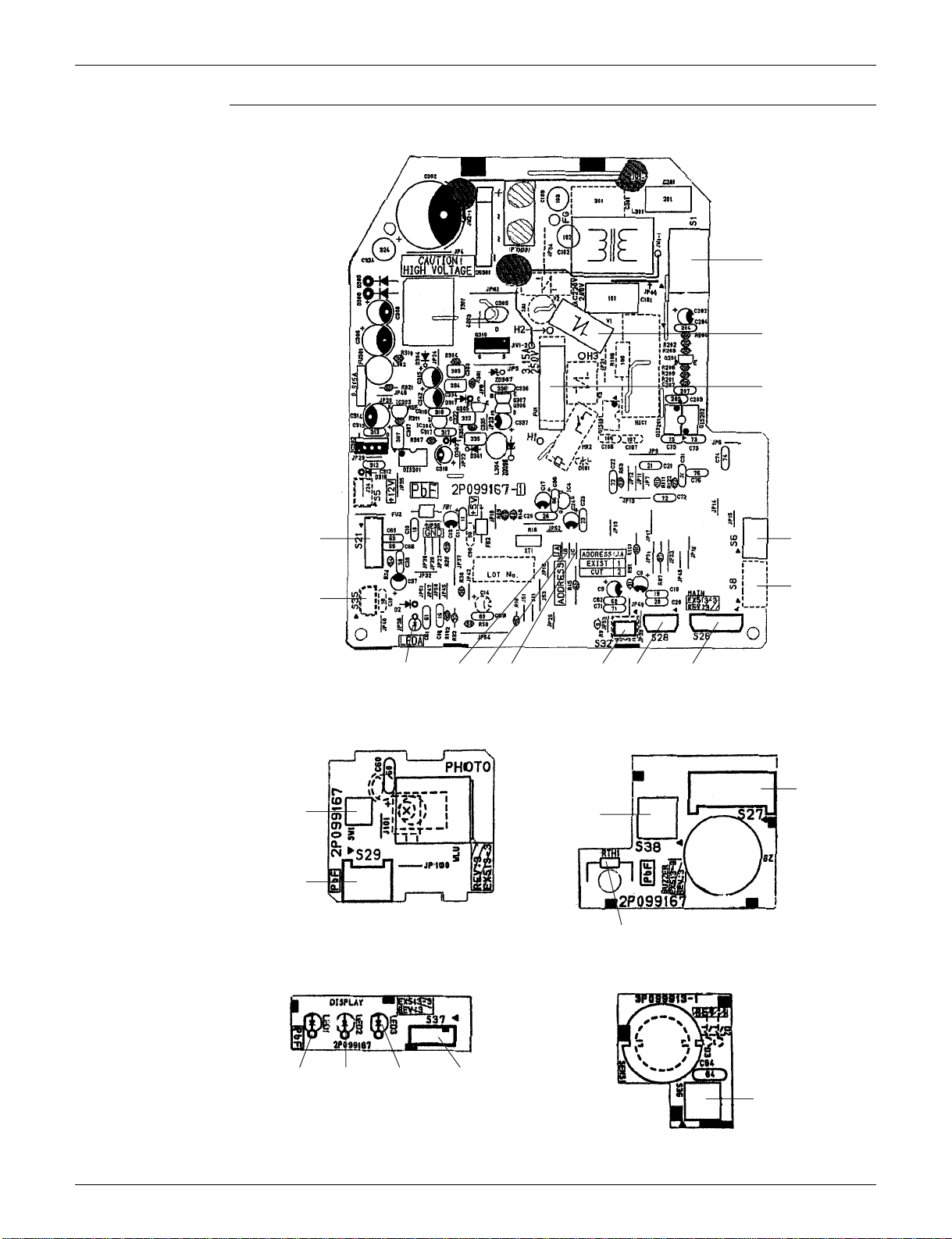
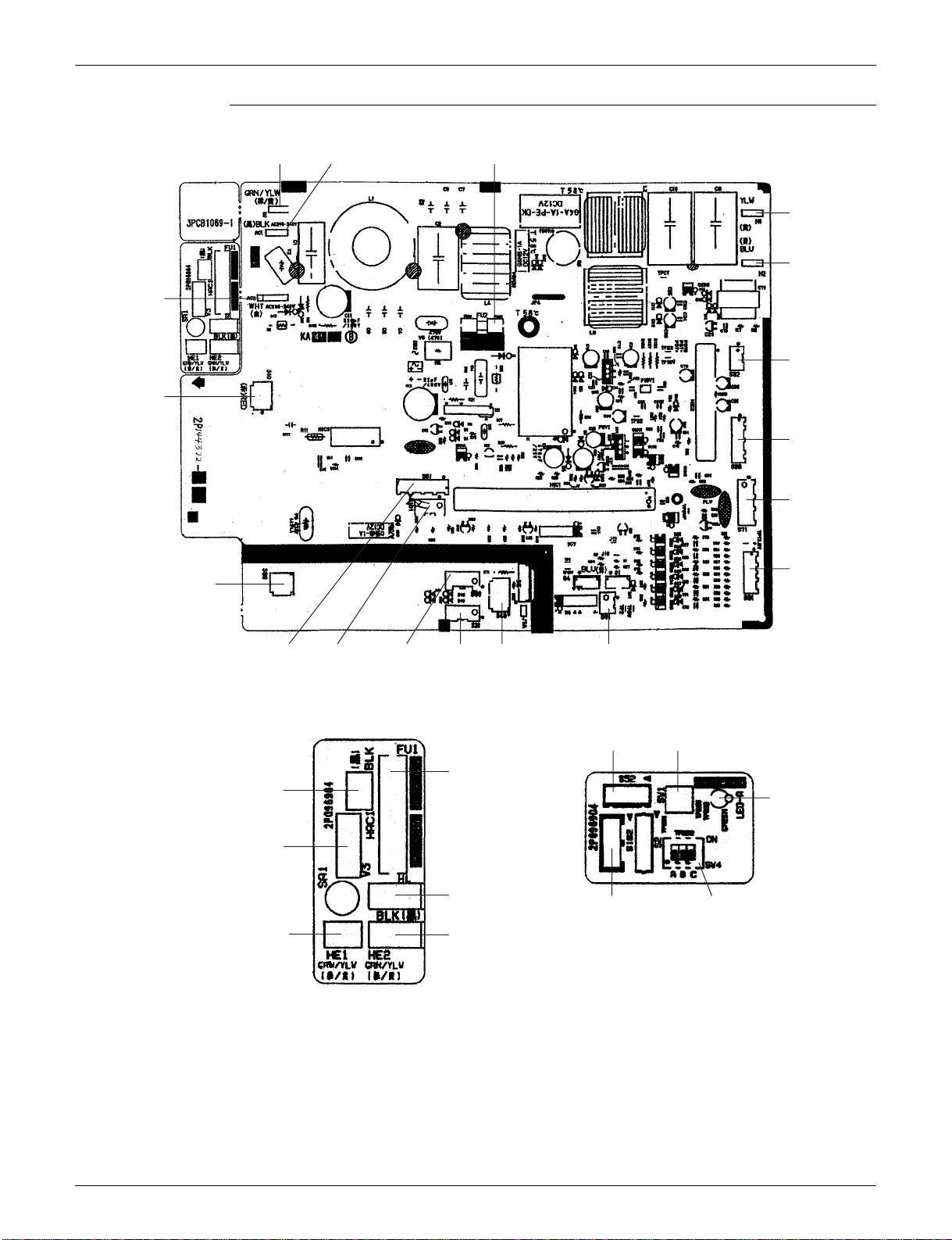
PCB Detail PCB(1): Control PCB (indoor unit)
PCB(2): Signal Receiver PCB
Control PCB
S21
V1 Fu1 S1
Signal Receiver PCB
SW7
LED1
LED2
LED3
RTH1
S27
S7
S6
S35
PCB(3): INTELLIGENT EYE sensor PCB
S36
S32JCJBJALED A
S26
(R4011)
(R3321)
Printed Circuit Board Connector Wiring Diag ram 9

Printed Circuit Board Connector Wiring Diagram SiUS04-702
1.2 FTXS15/18/24DVJU
Connectors PCB(1) (Cont r ol PC B) (indoo r unit)
1) S1 Connector for fan motor
2) S6 Connector for swing motor (horizontal blades)
3) S8 Connector for swing motor (vertical blades)
4) S21 Connector for centralized control (HA)
5) S26 Connector for buzzer PCB
6) S28 Connector for signal receiver PCB
7) S32 Connector for heat exchanger thermistor
8) S35 Connector for Intelligent Eye sensor PCB
PCB(2) (Signal Receiver PCB)
1) S29 Connector for control PCB
PCB(3) (Buzzer PCB)
1) S27 Connector for control PCB
2) S38 Connector for display PCB
PCB(4) (Display PCB)
1) S37 Connector for buzzer PCB
PCB(5) (INTELLIGENT EYE sensor PCB)
1) S36 Connector for control PCB
Note: Other designations
PCB(1) (Control PCB) (indoor unit)
1) V1 Varistor
2) JA Address setting jumper
JB Fan speed setting when compressor is OFF on thermostat
JC Power failur e recovery functio n
3) FU1 Fuse (3.15A)
4) LED A LED for service monitor (green)
PCB(2) (Signal Receiver PCB)
1) SW1 Forced operation ON/OFF switch
PCB(3) (Buzzer PCB)
1) RTH1 Room temperature thermistor
Refer to page 281 for detail.
∗
PCB(4) (Display PCB)
1) LED1 LED for operation (green)
2) LED2 LED for timer (yellow)
3) LED3 LED for Home Leave operation (red)
10 Printed Circuit Board Connector Wiring Diagram
SiUS04-702 Printed Circuit Board Connector Wiring Diagram
PCB Detail PCB(1): Control PCB (indoor unit)
S1
V1
FU1
S21
S6
S8
S35
S28S32JCJBJALED A
S26
(R2860)
PCB(2): Signal Receiver PCB PCB(3): Buzzer PCB
S27
SW1
S38
S29
(R2861)
RTH1
(R2862)
PCB(4): Display PCB PCB(5): INTELLIGENT EYE sensor PCB
LED1 LED2 LED3 S37
(R2863)
S36
(R2864)
Printed Circuit Board Connector Wiring Diag ram 11

Printed Circuit Board Connector Wiring Diagram SiUS04-702
1.3 RX09/12FVJU
Connectors PCB(1)(Filter PCB)
1) S11 Connector for control PCB
PCB(2)(Control PCB) (outdoor unit)
1) S10 Connector for filter PCB
2) S20 Connector for electronic expansion valve coil
3) S30 Connector for compressor motor
4) S40 Connector for overload protector
5) S70 Connector for fan motor
6) S80 Connector for four way valve coil
7) S90 Connector for thermistors
(outdoor air, heat exchanger, discharge pipe)
8) HC3, HC4, HL3, HN3 Connector for filter PCB
Note: Other designations
PCB(1)(Filter PCB)
1) FU3 Fuse (20A)
2) V2, V3 Varistor
PCB(2)(Control PCB) (outdoor unit)
1) FU1, FU2 Fuse (3.15A)
2) LED A Service monitor LED
3) V1 Varistor
12 Printed Circuit Board Connector Wiring Diagram
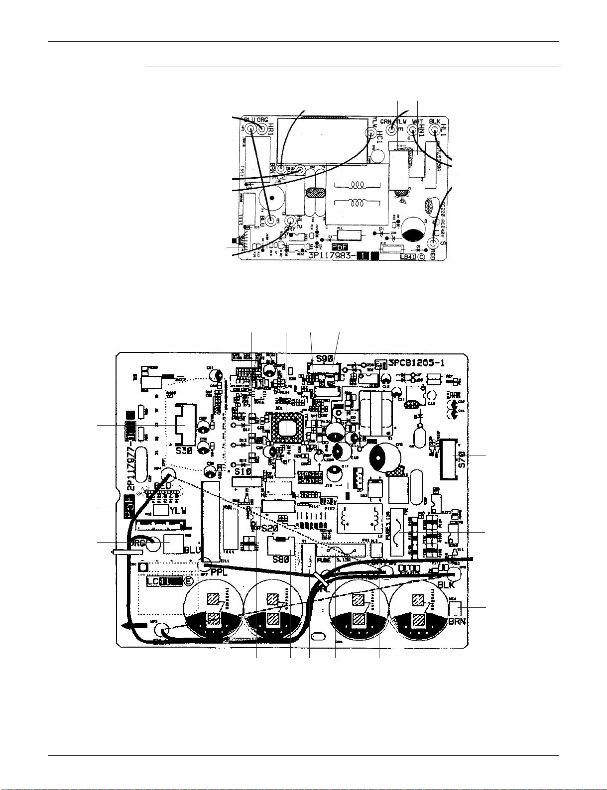
SiUS04-702 Printed Circuit Board Connector Wiring Diagram
PCB Detail PCB(1): Filter PCB
V3 V2
FU3(20A)
S11
(R6969)
PCB(2): Control PCB (outdoor unit)
S30
HC3
HN3
S10
S40 LED A S90
S70
FU2(3.15A)
HC4
HL3FU1(3.15A)V1S80S20
(R6970)
Printed Circuit Board Connector Wiring Diag ram 13

Printed Circuit Board Connector Wiring Diagram SiUS04-702
1.4 RX15/18/24FVJU
Connectors PCB(1)(Control PCB) (outdoor unit)
1) S10, AC2 Connector for terminal strip
2) S20 Connector for electronic expansion valve coil
3) S31, S32 Connector for SPM
4) S33, S71 Connector for MID
5) S40 Connector for overload protector
6) S51, S101 Connector for service monitor PCB
7) S80 Connector for four way valve coil
8) S90 Connector for thermistors
(outdoor air, heat exchanger, and discharge pipe)
9) S91 Connector for fin thermistor
10)AC1, E Connector for power supply PCB
11)H1, H2 Connector for diode bridge
PCB(2)(Power Supply PCB)
1) HL Connector for terminal strip
2) HAC1, HE1 Connector for control PCB
3) HE2 Connector for earth
PCB(3)(Service Monitor PCB)
1) S52, S102 Connector for control PCB
MID
1) S34, S72 Connector for control PCB
2) S70 Connector for fan motor
SPM
1) CN11, CN14 Connector for control PCB
2) L1, L2 Connector for reactor
Note: Other Designations
PCB(1)(Control PCB) (outdoor unit)
1) FU2 Fuse (3.15A)
PCB(2)(Power Supply PCB)
1) FU1 Fuse (30A)
2) V3 Varistor
PCB(3)(Service Monitor PCB)
1) LED A Service monitor LED
2) SW1 Forced operation ON/OFF switch
3) SW4 Local setting switch
MID
1) FU201 Fuse (3.15A)
14 Printed Circuit Board Connector Wiring Diagram
SiUS04-702 Printed Circuit Board Connector Wiring Diagram
PCB Detail PCB(1): Control PCB (outdoor unit)
E AC1 FU2(3.15A)
H1
H2
AC2
S32
S10
S33
S71
S80
S40S20S90S101S51
PCB(2): Power Supply PCB Servic e M onitor PCB
FU1(30A)
HAC1
V3
HL
HE1
HE2
(R2866)
S91
S52
SW1
S102 SW4
S31
(R6971)
LED A
(R5140)
Printed Circuit Board Connector Wiring Diag ram 15
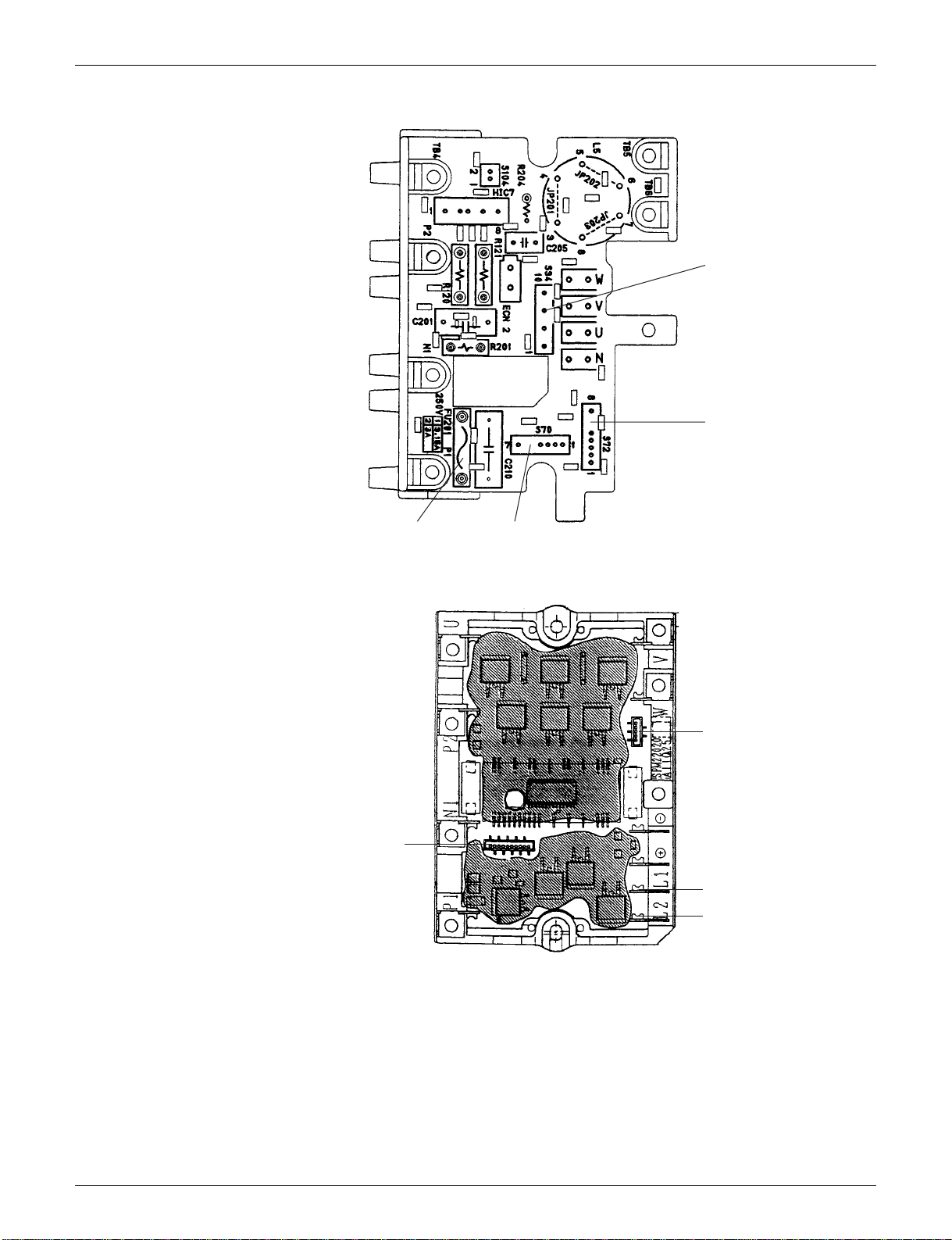
Printed Circuit Board Connector Wiring Diagram SiUS04-702
MID
S34
S72
SPM
CN14
S70FU201 (3.15A)
(R2868)
CN11
L1
L2
(R2869)
16 Printed Circuit Board Connector Wiring Diagram

SiUS04-702
Part 4
Function and Control
1. Main Functions.........................................................................................19
1.1 Frequency Principle................................................................................... 19
1.2 Power-Airflow Dual Flaps, Wide-Angle Louvres and Auto-Swing ............. 21
1.3 Fan Speed Control for Indoor Units........................................................... 22
1.4 Programme Dry Function ............................... ............... ................ ............ 23
1.5 Automatic Operation.............................. ............... ................ ............... ...... 24
1.6 Thermostat Control.................................................................................... 25
1.7 NIGHT SET Mode ..................................................................................... 26
1.8 INTELLIGENT EYE............... .................................................................... 27
1.9 HOME LEAVE Operation .......................................................................... 29
1.10 Inverter POWERFUL Operation...................................... ................ .......... 30
1.11 Other Functions................... ................ ............... ................ ............... ........ 31
2. Function of Thermistor.............................................................................33
2.1 Heat Pump Model..... ................ ............... ................ ............... ............... .... 3 3
3. Control Specification (09/12 Class)..........................................................34
3.1 Mode Hierarchy............... .......................................................................... 34
3.2 Frequency Control..................................................................................... 35
3.3 Controls at Mode Changing / Start-up....................................................... 37
3.4 Discharge Pipe Temperature Control................................... ............... ...... 38
3.5 Input Current Control................................................................................. 39
3.6 Freeze-up Protection Control .............. ............... ................ ............... ........ 39
3.7 Heating Peak-cut Control .......................................................................... 40
3.8 Fan Control................................................................................................ 40
3.9 Liquid Compression Protection Function 2 ................ ............................... . 40
3.10 Defrost Control ............................... ................ ............... ................ ............ 41
3.11 Electronic Expansion Valve Control .......................................................... 42
3.12 Malfunctions .............................................................................................. 45
3.13 Forced Operation Mode ............................................................................ 46
3.14 Additional Function... ................ ............... ................ ............... ................... 46
4. Control Specification (15/18/24 Class).....................................................47
4.1 Mode Hierarchy............... .......................................................................... 47
4.2 Frequency Control..................................................................................... 48
4.3 Controls at Mode Changing / Start-up....................................................... 50
4.4 Discharge Pipe Temperature Control................................... ............... ...... 51
4.5 Input Current Control................................................................................. 52
4.6 Freeze-up Protection Control .............. ............... ................ ............... ........ 53
4.7 Heating Peak-cut Control .......................................................................... 53
4.8 Fan Control................................................................................................ 54
4.9 Liquid Compression Protection Function 2 ................ ............................... . 54
4.10 Low Hz High Pressure Limit................ ............... ................ ............... ........ 55
4.11 Defrost Control ............................... ................ ............... ................ ............ 55
Function and Control 17

SiUS04-702
4.12 Electronic Expansion Valve Control .......................................................... 56
4.13 Malfunctions .............................................................................................. 59
4.14 Forced Operation Mode ............................................................................ 60
4.15 Additional Function... ................ ............... ................ ............... ................... 60
18 Function and Control
SiUS04-702 Main Functions
1. Main Functions
Note: See the list of functions for the functions applicable to different models.
1.1 Frequency Principle
Main Control
Parameters
Additional
Control
Parameters
The compressor is frequency-controlled during normal operation. The target frequency is set by the
following 2 parameters coming from the operating indoor unit:
The load condition of the operating indoor unit
The difference between the room temperature and the set temperature
The target frequency is adapted by additional parameters in the following cases:
Frequency restrictions
Initial settings
Forced cooling operation
Inverter Principle To regulate the capacity, a frequency control is needed. The inverter makes it possible to vary the
rotation speed of the compressor. The following table explains the conversion principle:
Phase Description
1 The supplied AC power source is converted into the DC power source for the present.
2 The DC power source is reconverted into the three phase AC power source with variable
frequency.
When the frequency increases, the ro tation speed of the c ompressor increases resulting
in an increased refrigerant circulation. This leads to a higher amount of the heat
exchange per unit.
When the frequency decreases, the rotation speed of the compressor decreases
resulting in a dec reased refrige rant cir culation. This lead s to a lower am ount of the heat
exchange per unit.
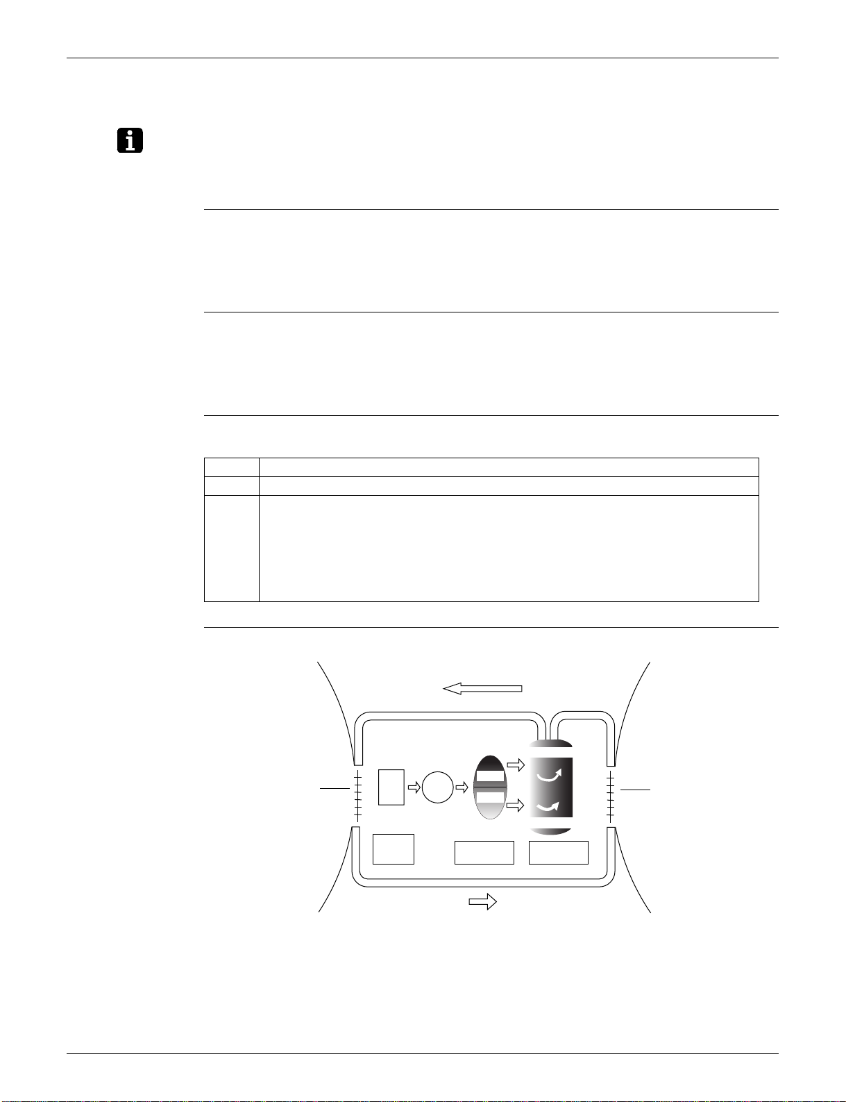
Drawing of
Inverter
The following drawing shows a schematic view of the inverter principle:
Refrigerant circulation rate (high)
Amount of heat
exchanged air (large)
Amount of heat
exchanged air (small)
AC
power
freq=
constant
high f
DC
power
low f
50 Hz
freq=variable
60 Hz
Refrigerant circulation rate (low)
high speed
low speed
capacity=
variable
Amount of heat
exchanged air (large)
Amount of heat
exchanged air (small)
(R2812)
Function and Control 19
 Loading...