

Daikin FTXS30HVJU, FTXS36HVJU, FTXS90HVMA, FTXS100HVMA, FTXS90JVMA Service Manual
...
REMOVAL
PROCEDURE
SERVICE MANUAL
Indoor Unit
Inverter
Wall Mounted Type
7.1/8.0/9.0/10.0 kW Class
30000/36000 Btu/h Class
Si04-958

Service Manual
Removal Procedure
Indoor Unit
zCooling Only zHeat Pump
FTKS71HVMG FTXS30HVJU
FTXS36HVJU
FTXS80HVMA
FTXS90HVMA
FTXS100HVMA
FTXS90JVMA
FTXS100JVMA

Si04-958
Removal Procedure 1
Table of Contents
1. Removal of Air Filters / Front Panel ........................................................2
2. Removal of Front Grille ...........................................................................5
3. Removal of Electrical Box .......................................................................8
4. Removal of PCBs..................................................................................12
5. Removal of Horizontal Blades / Swing Motors ......................................20
6. Removal of Fan Motor...........................................................................28
7. Removal of Indoor Heat Exchanger ......................................................31
8. Removal of Fan Rotor ...........................................................................34
9. Removal of Vertical Blade ASSY ..........................................................36
Note:
The illustrations may be slightly different depending on the model.

Removal of Air Filters / Front Panel Si04-958
2 Removal Procedure
1. Removal of Air Filters / Front Panel
Procedure Warning Be sure to wait for 10 minutes or more after turning off all power
supplies before disassembling work.
Step
Procedure Points
1. Appearance features
Warning
Dangerous: High voltage
A high voltage is applied to all
the electric circuits of this
product including
thermistors.
When the signal receiver
catches a signal from the
remote controller, the
receiving tone sounds and
the operation lamp blinks
immediately to confirm the
signal reception.
When the [ON/OFF] button
is kept pressed for 5
seconds, the forced cooling
operation is performed for
about 15 minutes.
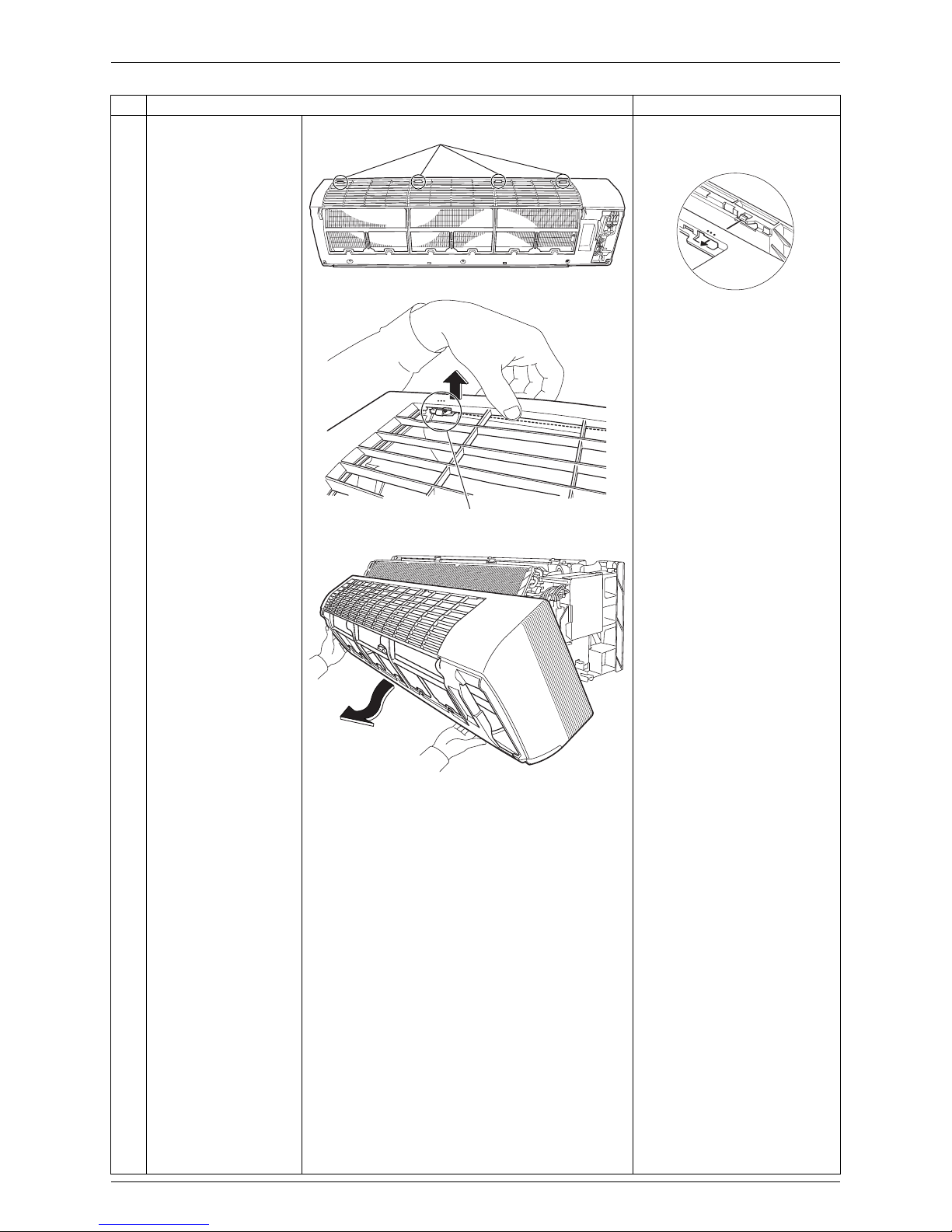
2. Remove the air filters.
1
Open the front panel to
the position where it
stops.
2
Slightly push up the
center knob of the air
filter and unfasten the
hooks.
The 3 filters are
interchangeable.
Insert the air filter with the
"FRONT" mark faced up.
The air filter can be set
easily by inserting it along
the guides.
Be sure to insert the hooks
(at 2 lower positions) when
reassembling the air filter.
3
Pull out the air filter
downward and remove
it.
(R9473)
ON/OFF
(R16974)
Operation lamp
TIMER lampSignal receiver
Room temperature thermistor[ON/OFF] button
INTELLIGENT
EYE sensor
INTELLIGENT
EYE lamp
(R9475)
Front Panel
(R13625)
Air filter
Hook
Si04-958 Removal of Air Filters / Front Panel
Removal Procedure 3
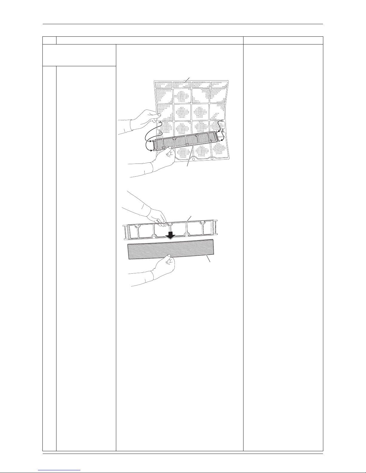
3. Remove the Titanium
apatite photocatalytic airpurifying filters.
1
Remove the Titanium
apatite photocatalytic
air-purifying filter ASSY
by unfastening the
projections from the
back of the air filter
frame.
The 3 filters are
interchangeable.
2
Remove the Titanium
apatite photocatalytic
air-purifying filter from
its frame.
Step
Procedure Points
(R9477)
Air filter
Titanium apatite photocatalytic
air-purifying filter ASSY
(R9478)
Frame
Titanium apatite photocatalytic
air-purifying filter
Removal of Air Filters / Front Panel Si04-958
4 Removal Procedure
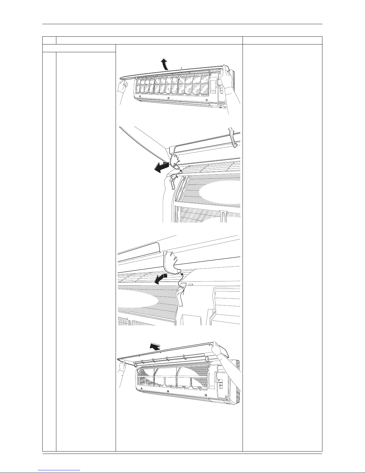
4. Remove the front panel.
1
While opening the front
panel further than it
stops, release both the
shafts.
Slide the front panel from
side to side to release each
shaft.
When reassembling the front
panel, fit the right and left
rotary shafts one by one into
the grooves and fully push
them into position.
2
Remove the front
panel.
Step
Procedure Points
(R9479)
Front Panel
(R9480)
(R9481)
(R9482)
Si04-958 Removal of Front Grille
Removal Procedure 5
2. Removal of Front Grille
Procedure Warning Be sure to wait for 10 minutes or more after turning off all power
supplies before disassembling work.
Step
Procedure Points
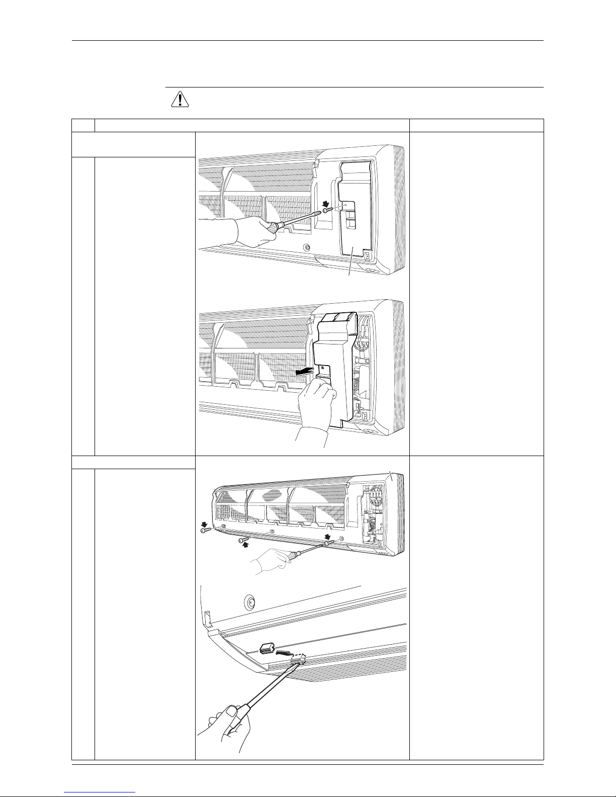
1. Remove the service
cover.
1
Remove the screw and
remove the service
cover.
You can remove the front
grille without detaching the
service cover.
2. Remove the front grille.
1
Remove the 3 screws
of the front grille.
Refer to the removal
procedure in a reverse way
when reassembling.
2
Remove the 3 screw
covers with a flat
screwdriver.
(R9483)
Service cover
(R9484)
(R9485)
Front grille
(R16266)

Removal of Front Grille Si04-958
6 Removal Procedure
3
Remove the lower 3
screws.
4
Remove the 3 front
grille fixtures.
The Illustration shows the
left fixture.
Step
Procedure Points
(R9488)
(R9489)
Front grille fixture
(R9490)
Si04-958 Removal of Front Grille
Removal Procedure 7
5
Unfasten the 4 hooks
on the top of the front
grille.
The convex marks (...) on
the front panel indicate the
position of the hooks.
6
Pull the upper part of
the front grille out and
lift the lower part up,
and then remove the
front grille.
When reassembling, make
sure that all the 4 hooks are
fastened as they were.
Step
Procedure Points
(R9486)
Hook
(R9487)
Hook
(R12715)
(R9492)
Removal of Electrical Box Si04-958
8 Removal Procedure
3. Removal of Electrical Box
Procedure Warning Be sure to wait for 10 minutes or more after turning off all power
supplies before disassembling work.
Step
Procedure Points
1. Layout of the parts Preparation
Remove the front grille
according to the “Removal of
Front Grille.”
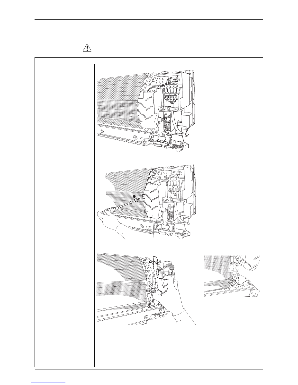
2. Remove the drip proof
plate.
The shape of the drip proof
plate differs by the model.
1
Remove the screw.
2
Remove the drip proof
plate from the indoor
heat exchanger.
When reassembling, fit the
hook to the indoor heat
exchanger.
1
2
3
(R9493)
1
2
3
(R9494)
Drip proof plate
(R9496)
(R9495)
Si04-958 Removal of Electrical Box
Removal Procedure 9
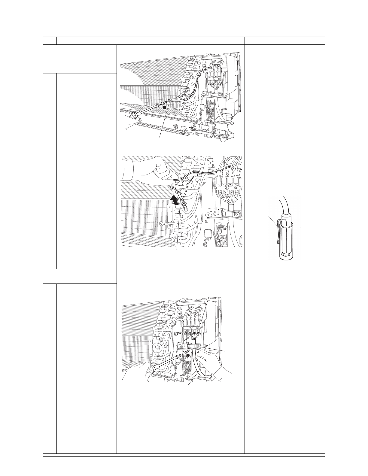
3. Release the earth /
ground wire and the
indoor heat exchanger
thermistor.
1
Remove the screw and
release the earth /
ground wire.
2
Pull out the indoor heat
exchanger thermistor.
The position of the indoor
heat exchanger thermistor is
slightly different depending
on the model.
Be careful not to lose the clip
of the thermistor.
4. Remove the electrical
box.
1
Remove the screw and
remove the wire
retainer.
Remove the 4 screws
on the terminal board
and disconnect the
connecting wire.
Step
Procedure Points
1
2
3
(R18588)
Earth / ground wire
1
2
3
(R9498)
Indoor heat exchanger thermistor
Clip
(R11268)
1
2
3
(R17230)
Terminal board
Wire
retainer
Connecting wire
Removal of Electrical Box Si04-958
10 Removal Procedure
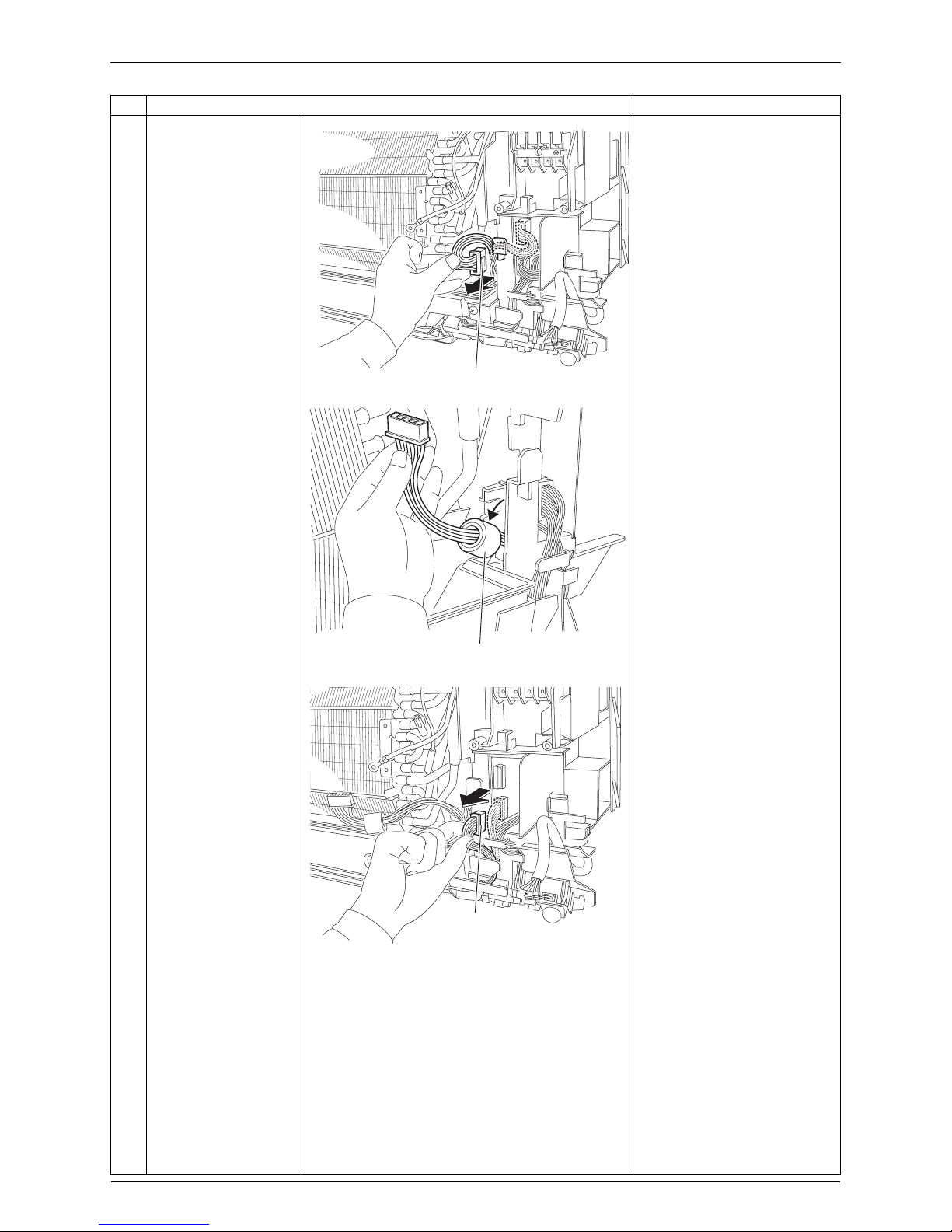
2
Disconnect the
connector for the fan
motor [S1] and release
the harness from the
hook.
3
Release the ferrite
core.
4
Disconnect the
connector for the swing
motors [S41].
Step
Procedure Points
1
2
3
(R9500)
[S1]
(R9501)
Ferrite core
(R9502)
[S41]
 Loading...