

Daikin FTXN-M, RXN-M User manual
INSTALLATION
MANUAL
R410A SPLIT SERIES
MODELS
FTXN25MV1B RXN25MV1B
FTXN35MV1B RXN35MV1B
FTXN50MV1B RXN50MV1B
FTXN60MV1B RXN60MV1B
FTXN25MV1 RXN25MV1
FTXN35MV1 RXN35MV1
FTXN50MV1 RXN50MV1
FTXN60MV1 RXN60MV1
FTK25JXV1 RK25FXV1
Installation Manual
R410A Split Series
Manuale d’installazione
Serie Multiambienti R410A
Installationsanleitung
Split-Baureihe R410A
Manual de instalación
Serie Split R410A
Manuel d’installation
Série split R410A
Montaj kýlavuzlarý
R410A Split serisi
Руководство по монтажу
Серия R410A с раздельной установкой
English
Italiano
Deutsch
Español
Français
Türkçe
Русский
FTK35JXV1 RK35FXV1
FTK50JXV1 RK50CXV1
FTK60JXV1 RK60CXV1
IM-5WMYJ-1113(2)-DAIKIN
Part Number.: R08019039396B


Indoor Unit [FTXN/FTK]
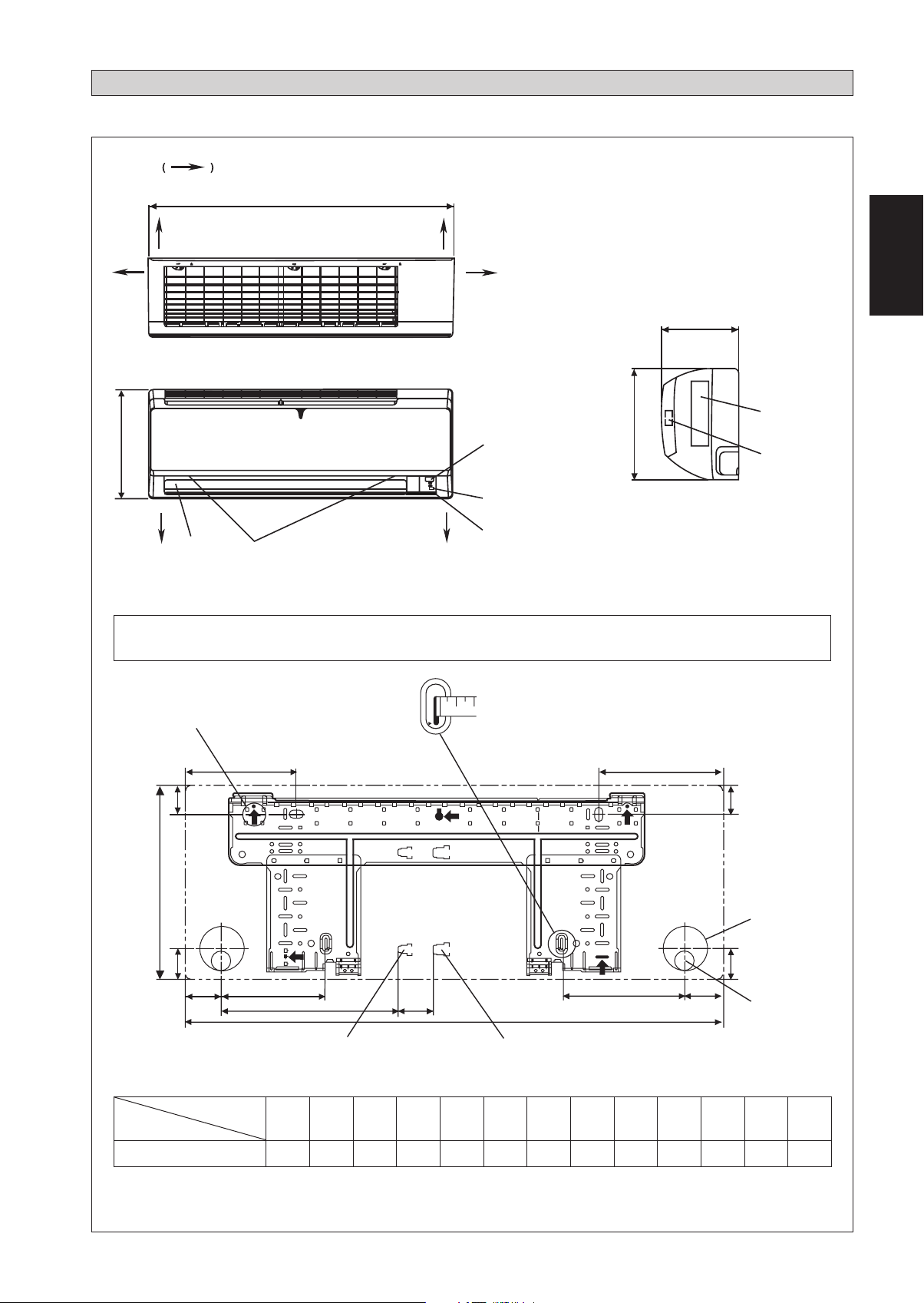
OUTLINE AND DIMENSIONS
THE MARK SHOWS PIPING DIRECTION
A
REAR REAR
TOP VIEW
B
BOTTOM
LOUVER
FRONT GRILLE FIXED SCREWS
(INSIDE)
FRONT VIEW
BOTTOM
RIGHTLEFT
B
SIGNAL RECEIVER
INDOOR UNIT
ON/OFF SWITCH
ROOM TEMPERATURE THERMISTOR
(INSIDE)
C
SIDE VIEW
English
Original Instruction
NAME PLATE
TERMINAL
BLOCK
WITH EARTH
TERMINAL
NOTE: PLEASE BASED ON ACTUAL INSTALLATION PLATE DESIGN IN THE UNIT FOR INSTALLATION PLATE
25/35 DIMENSION REFERENCE AT PAGE 1&2.
«
Recommended mounting plate retention spots
(5 spots in all)
D
F
B
G
H
J
L
Liquid pipe end
M
Use tape measure as shown.
Position the end of a tape measure at
A
Gas pipe end
Ñ
E
F
Through the wall
hole Ø 65mm
G
K
I
Drain hose position
Model
25/35
Dimension
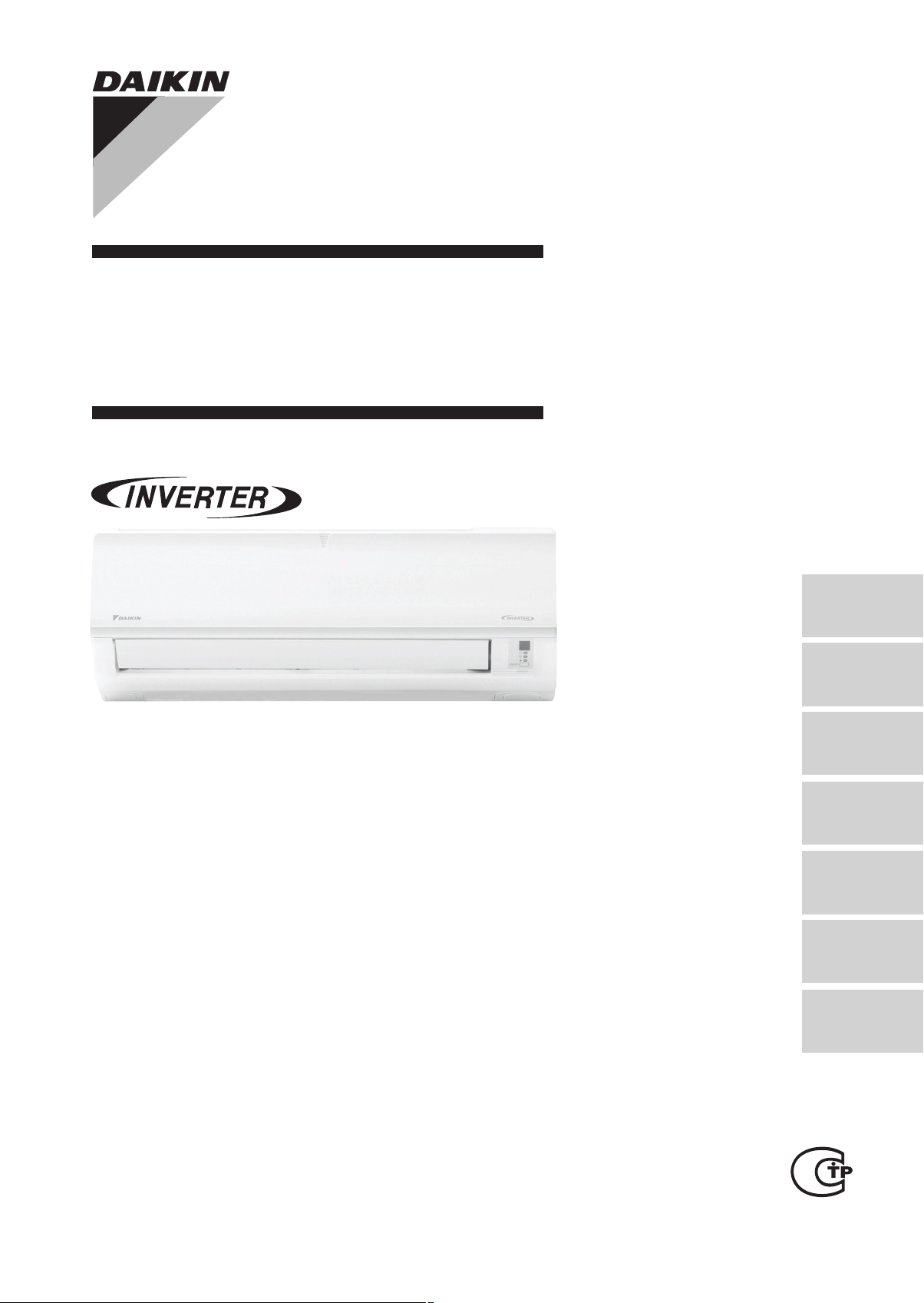
INSTALLATION PLATE 25/35
ABCDE FGHI JKLM
800 288 212 166 184 42 46 55 56 154 182 263 52
All dimensions are in mm
1-1
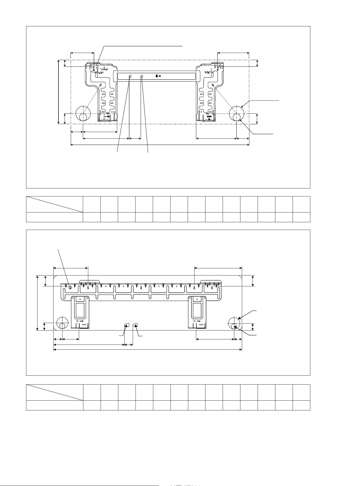
« Recommended mounting plate retention spots
(5 spots in all)
D
E
Model
25/35
F
B
G
Dimension
F
Through the wall
hole Ø 65mm
G
JH
Liquid pipe end
ML
ALTERNATIVE INSTALLATION PLATE 25/35
A
Gas pipe end
Drain hose position
IK
All dimensions are in mm
ABCDE FGHI JKLM
800 288 212 104 141 30 46 55 56 153 181 207 52
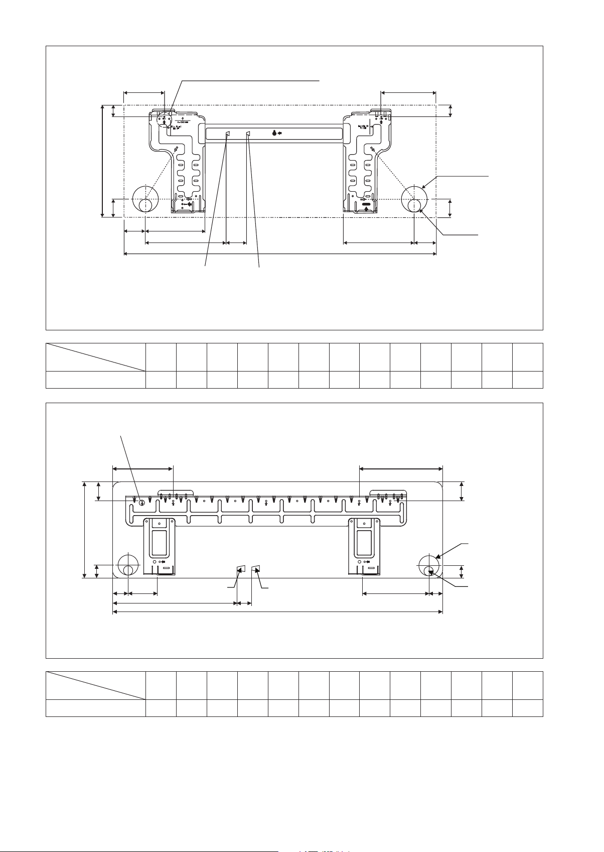
« Recommended mounting plate retention spots
(7 spots in all)
D
F
B
G
Liquid pipe end Gas pipe end
L
ABCDE FGHI JKLM
1065 310 229 190 173 61 40 45 48 91 219 580 45
Model
50/60
H
Dimension
J
M
A
INSTALLATION PLATE 50/60
E
F
Through the wall
hole Ø 65mm
G
K
I
Drain hose position
All dimensions are in mm
1-2
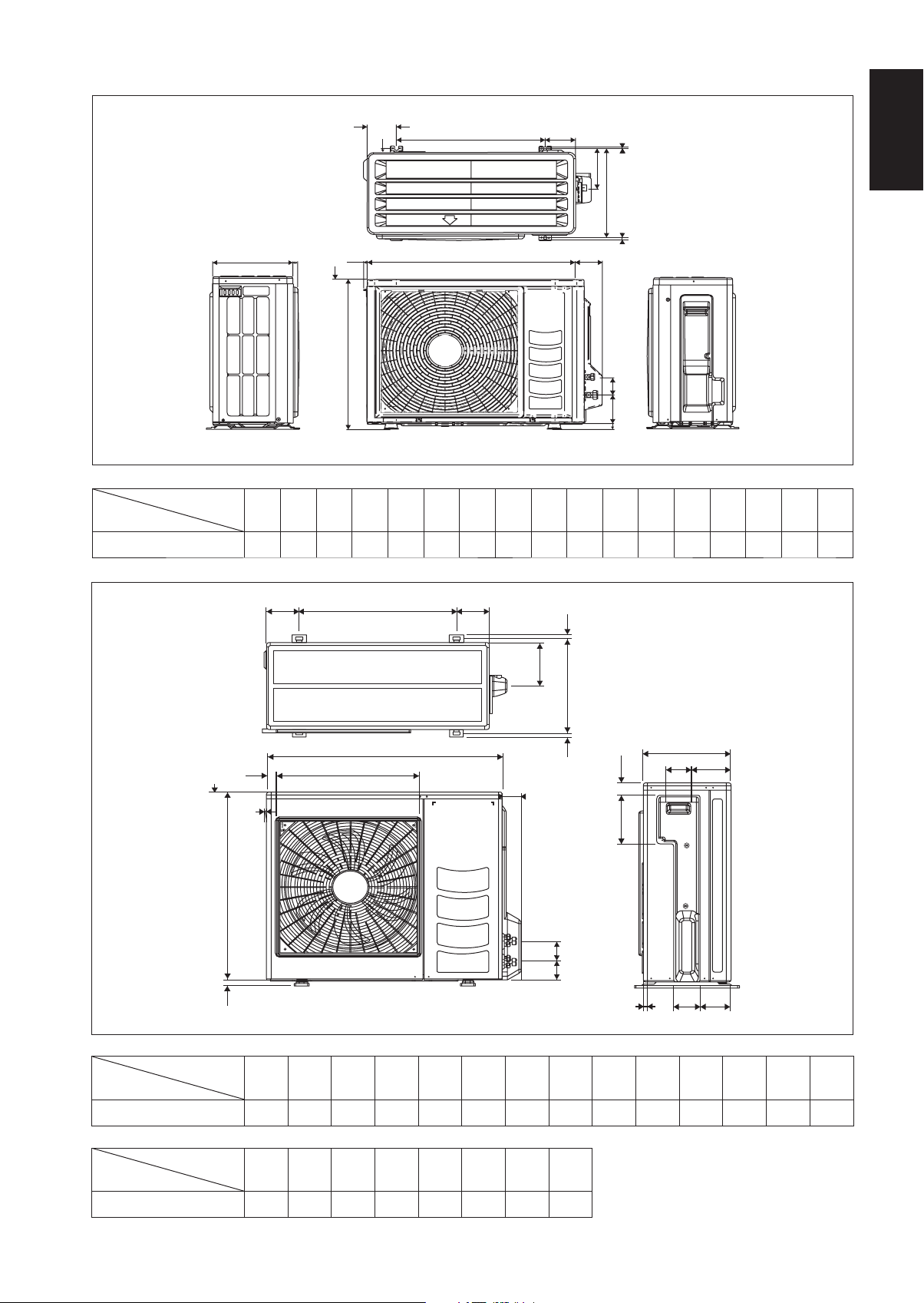
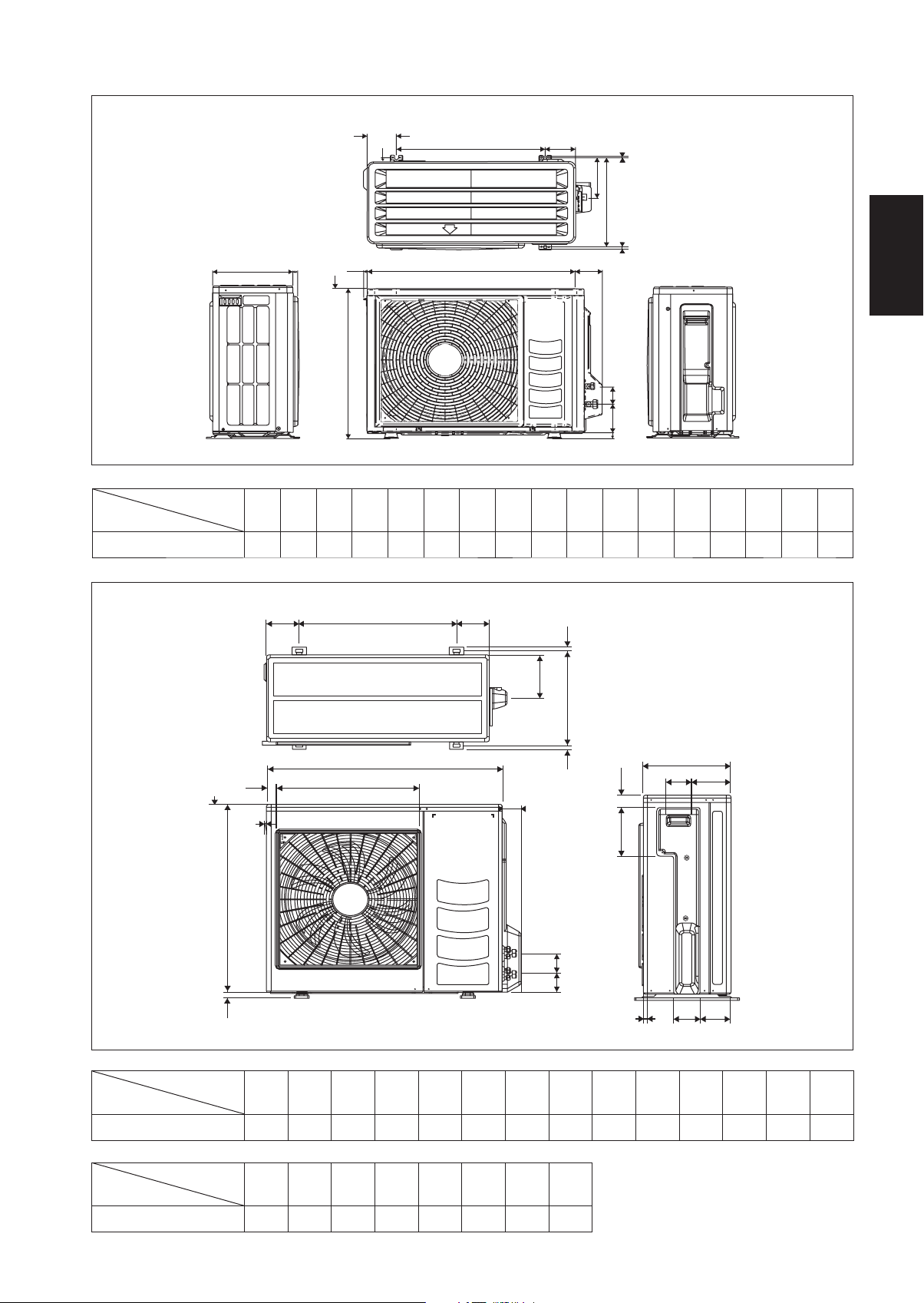
Outdoor Unit [RXN/RK]
All dimensions are in mm
OP
KL
M
Model
Dimension
EF
J
G
2.0
A
HI
N
Q
B
CD
ABCDE FGHI JKLMNOPQ
25/35 550 658 51 11 273 16 14 470 96 93 94 60 14 133 8 10 299
English
3.0
KLL
N
M
Q
A
O
V
B
P
D
U
N
F
E
S
R
All dimensions are in mm
C
GH
I
J
T
Dimension
Model
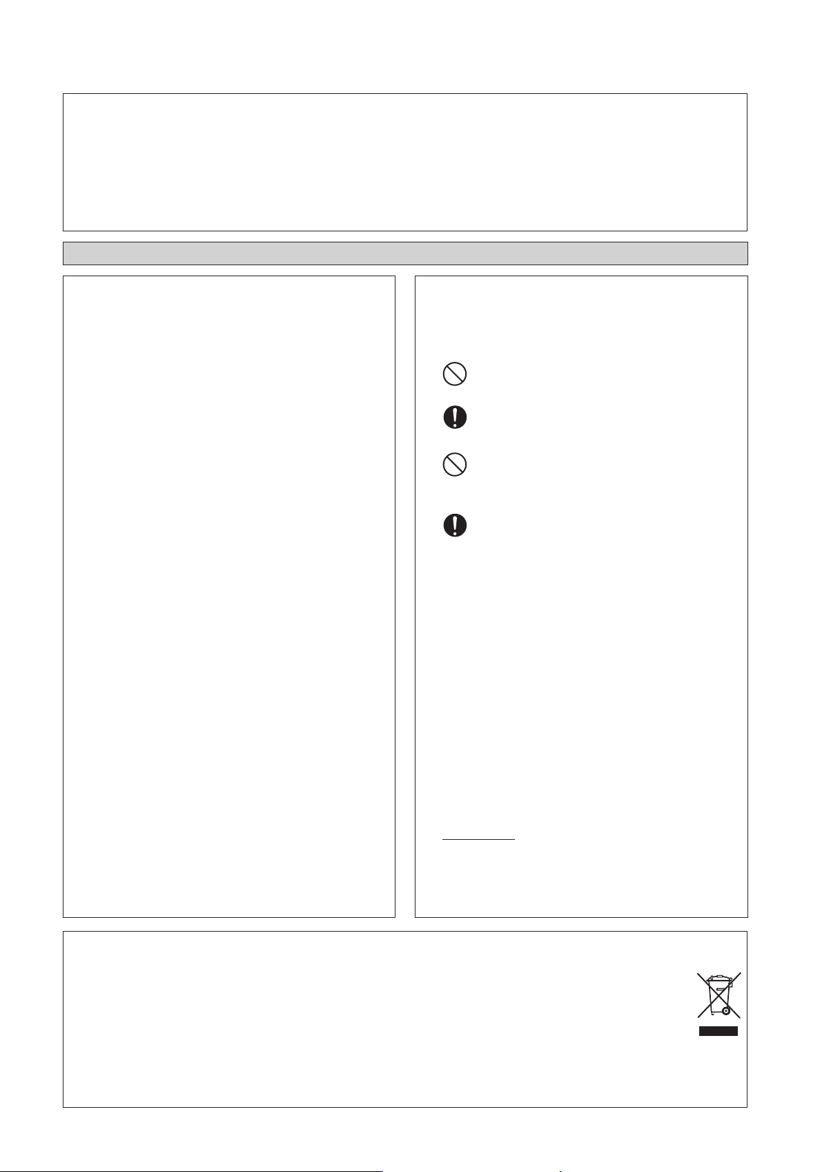
ABCDE FGHI JKLMN
50/60 855 730 328 520 179 46 93 149 101 113 603 126 164 15
Dimension
Model
OPQRSTUV
50/60 34 23 362 73 75 8 67 7
1-3
INSTALLATION MANUAL
This manual provides the procedures of installation to ensure a safe and good standard of operation for the air conditioner unit.
Special adjustment may be necessary to suit local requirement.
Before using your air conditioner, please read this instruction manual carefully and keep it for future reference.
This appliance is intended to be used by expert or trained users in shops, in light industry and on farms, or for commercial use by lay
persons.
This appliance is not intended for use by persons, including children, with reduced physical, sensory or mental capabilities, or lack of
experience and knowledge, unless they have been given supervision or instruction concerning use of the appliance by a person responsible
for their safety.
Children should be supervised to ensure that they do not play with the appliance.
SAFETY PRECAUTIONS
! WARNING ! CAUTION
Installation and maintenance should be performed by qualifi ed
•
persons who are familiar with local code and regulation, and
experienced with this type of appliance.
All fi eld wiring must be installed in accordance with the national
•
wiring regulation.
Ensure that the rated voltage of the unit corresponds to that of
•
the name plate before commencing wiring work according to
the wiring diagram.
The unit must be GROUNDED to prevent possible hazard due
•
to insulation failure.
All electrical wiring must not touch the water piping or any
•
moving parts of the fan motors.
Confi rm that the unit has been switched OFF before installing
•
or servicing the unit.
Disconnect from the main power supply before servicing the
•
air conditioner unit.
DO NOT pull out the power cord when the power is ON. This
•
may cause serious electrical shocks which may result in the
fi re hazards.
Keep the indoor and outdoor units, power cable and transmission
•
wiring, at least 1m from TVs and radios, to prevent distorted
pictures and static. {Depending on the type and source of the
electrical waves, static may be heard even when more than
1m away}.
Please take note of the following important points when
installing.
Do not install the unit where leakage of fl ammable gas may
•
occur.
If gas leaks and accumulates around the unit, it may cause
fi re ignition.
Ensure that drainage piping is connected properly.
•
If the drainage piping is not connected properly, it may
cause water leakage which will dampen the furniture.
Do not overcharge the unit.
•
This unit is factory pre-charged.
Overcharge will cause over-current or damage to the
compressor.
Ensure that the unit’s panel is closed after service or
•
installation.
Unsecured panels will cause the unit to operate noisily.
Sharp edges and coil surfaces are potential locations which
•
may cause injury hazards. Avoid from being in contact with
these places.
Before turning off the power supply, set the remote
•
controller’s ON/OFF switch to the “OFF” position to prevent
the nuisance tripping of the unit. If this is not done, the unit’s
fans will start turning automatically when power resumes, posing
a hazard to service personnel or the user.
Do not install the units at or near doorway.
•
Do not operate any heating apparatus too close to the air
•
conditioner unit or use in room where mineral oil, oil vapour
or oil steam exist, this may cause plastic part to melt or
deform as a result of excessive heat or chemical reaction.
When the unit is used in kitchen, keep fl our away from
•
into suction of the unit.
This unit is not suitable for factory used where cutting oil
•
mist or iron powder exist or voltage fl uctuates greatly.
Do not install the units at area like hot spring or oil refi nery
•
plant where sulphide gas exists.
Ensure the color of wires of the outdoor unit and the terminal
•
markings are same to the indoors
IMPORTANT: DO NOT INSTALL OR USE THE AIR
•
CONDITIONER UNIT IN A LAUNDRY ROOM.
Don’t use joined and twisted wires for incoming power
•
supply.
The equipment is not intended for use in a potentially
•
explosive atmosphere.
respectively.
going
Disposal requirements
NOTICE
Your air conditioning product is marked with this symbol. This means that electrical and electronic products shall not be mixed with
unsorted household waste.
Do not try to dismantle the system yourself: the dismantling of the air conditioning system, treatment of the refrigerant, of oil and of
other parts must be done by a qualifi ed installer in accordance with relevant local and national legislation.
Air conditioners must be treated at a specialized treatment facility for re-use, recycling and recovery. By ensuring this product is
disposed of correctly, you will help to prevent potential negative consequences for the environment and human health. Please contact
the installer or local authority for more information.
Batteries must be removed from the remote controller and disposed of separately in accordance with relevant local and national
legislation.
1-4

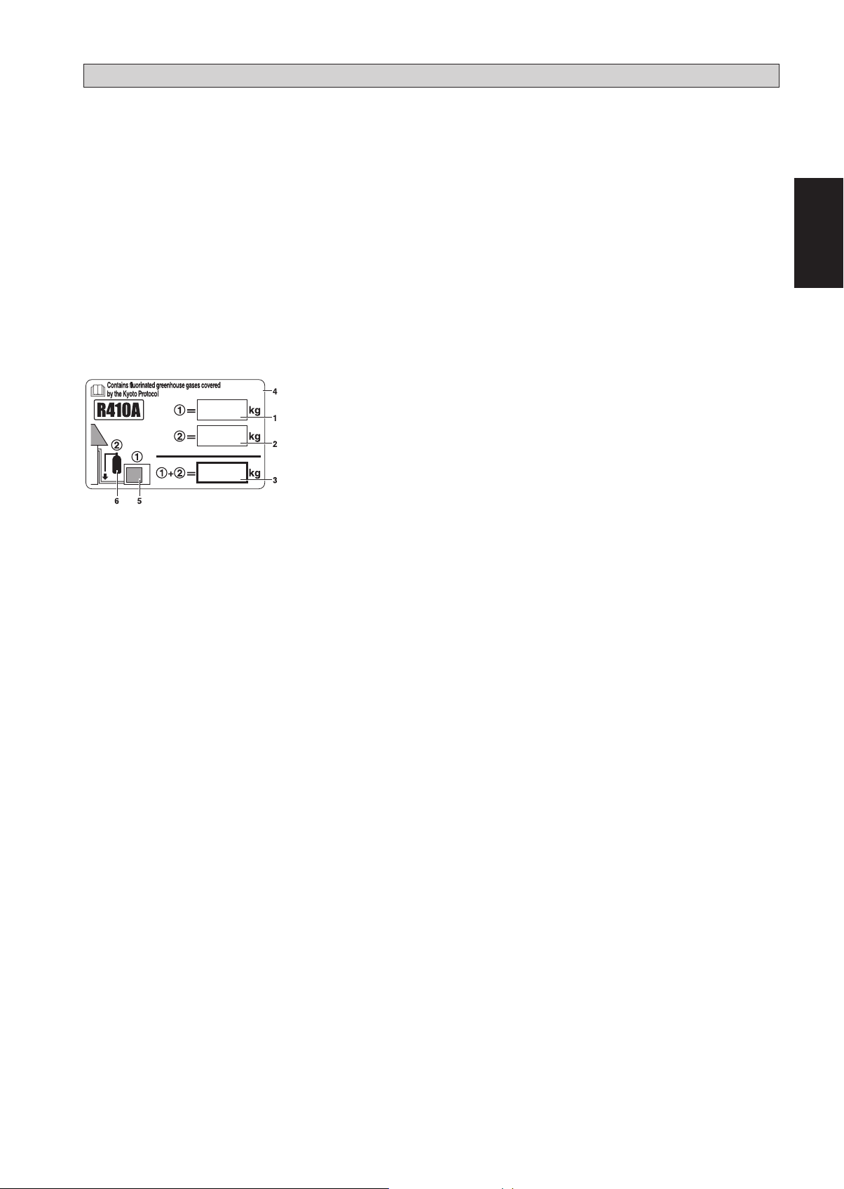
IMPORTANT
Important information regarding the refrigerant used
This product contains fluorinated greenhouse gases covered by the Kyoto Protocol.
Do not vent gases into the atmosphere.
Refrigerant type: R410A
(1)
GWP
(1)
Please fill in with indelible ink,
¢
¢
¢
on the refrigerant charge label supplied with the product.
The filled out label must be adhered in the proximity of the product charging port (e.g. onto the inside of the service cover).
value: 1975
GWP = Global Warming Potential
1 the factory refrigerant charge of the product,
2 the additional refrigerant amount charged in the field and
1 + 2 the total refrigerant charge
1
factory refrigerant charge of the product:
see unit name plate
additional refrigerant amount charged in the field
2
total refrigerant charge
3
contains fluorinated greenhouse gases covered by the Kyoto Protocol
4
outdoor unit
5
(2)
English
refrigerant cylinder and manifold for charging
6
(2)
In case of multiple indoor systems, only 1 label must be adhered*, mentioning the total factory refrigerant charge of all
indoor units connected in the refrigerant system.
Periodical inspections for refrigerant leaks may be required depending on European or local legislation. Please contact your
local dealer for more information.
* on the outdoor unit
1-5

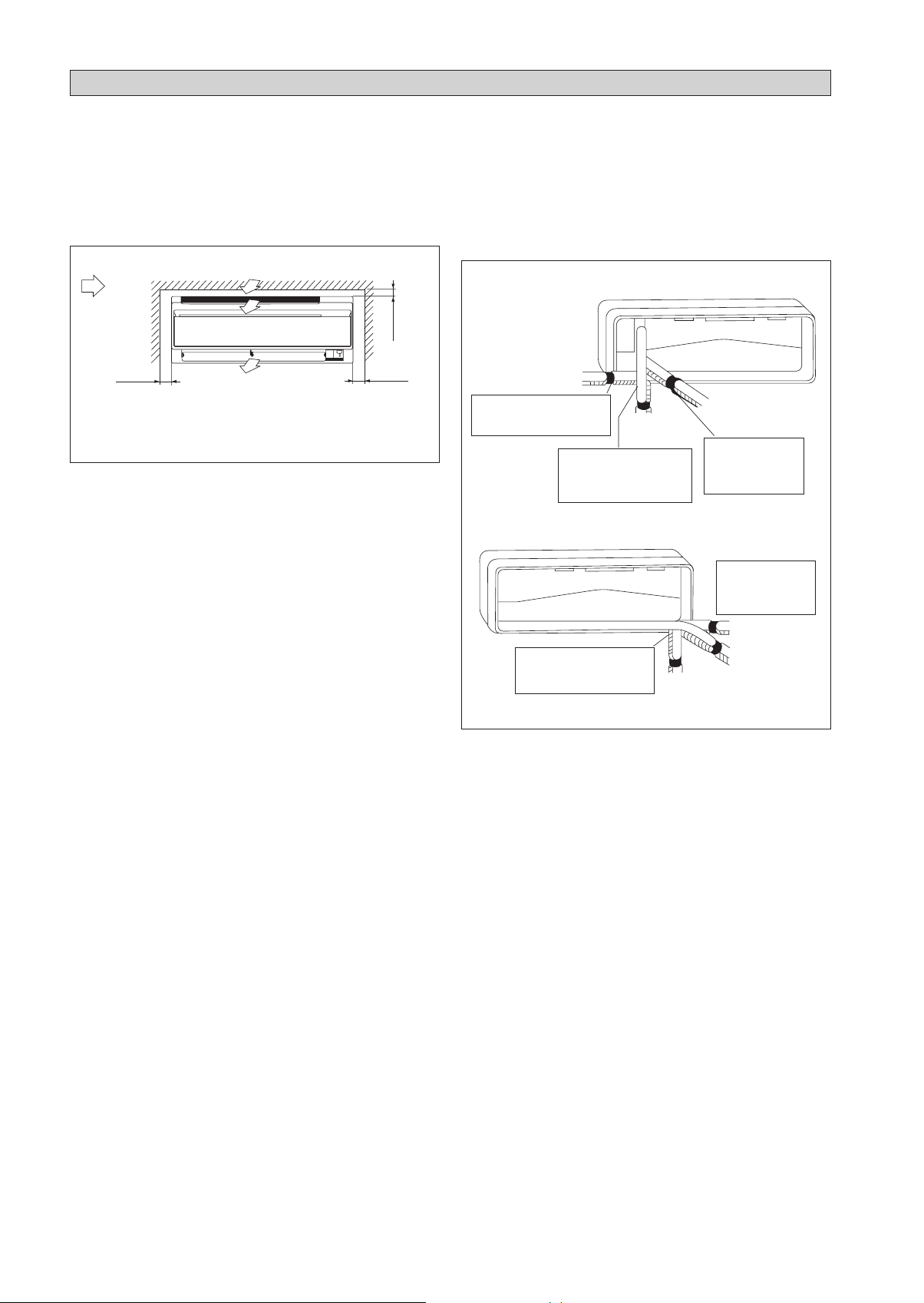
INSTALLATION DIAGRAM
Indoor Unit
50mm or more from walls
(on both sides)
Front panel
Air filter
Outdoor Unit
M4 x 12L
30mm or more from ceiling
Service lid
Opening service lid
ó
Service lid is opening/
closing type.
Opening method
ó
1) Remove the service lid
screws.
2) Pull out the service lid
diagonally down in the
direction of the arrow.
3) Pull down.
Caulk pipe
hole gap
with putty.
500mm from wall
Cut thermal insulation pipe to an
appropriate length and wrap it with
tape, making sure that no gap is left
in the insulation pipe’s cut line.
Wrap the insulation pipe
with the finishing tape
from bottom to top.
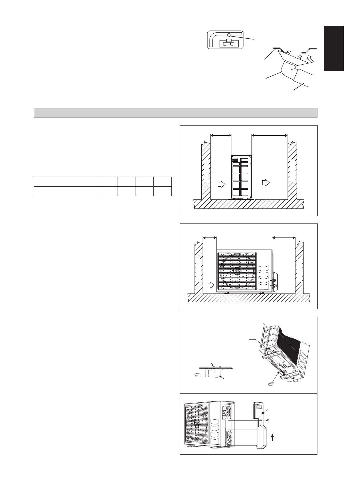
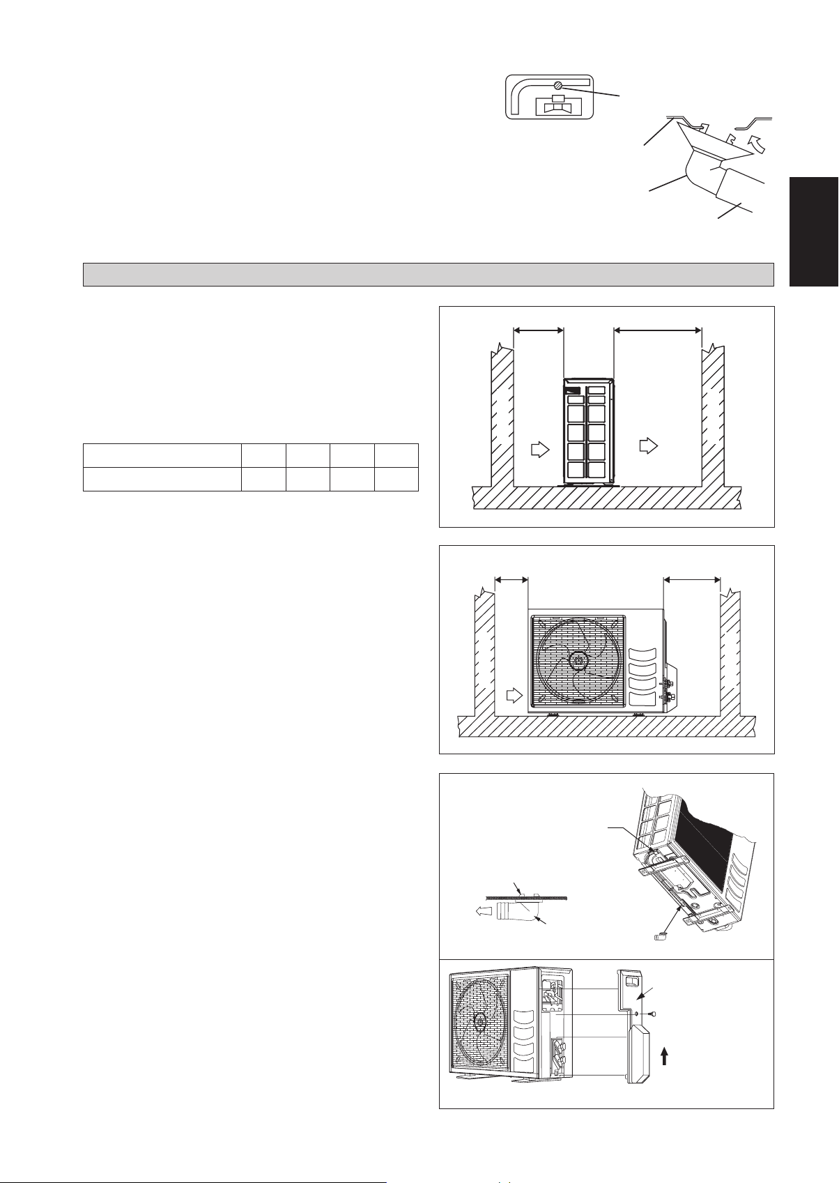
INSTALLATION OF THE OUTDOOR UNIT (RXN/RK 25/35)
Where a wall or other obstacle is in the path of outdoor unit’s intake or exhaust airflow, follow the installation guidelines
•
below.
For any of the below installation patterns, the wall height on the exhaust side should be 1200mm or less.
•
Wall facing one side
More than 50
More than 100
1200 or
less
Side View
Wall facing two sides
More
than 100
More than 50
Wall facing three sides
More than 150
More than 50
Top View
More than 150
More than 50
1-6
More than 300
Top View
Unit : mm
Drain work. (Heat Pump Unit Only)
1) Use drain plug for drainage.
2) If the drain port is covered by a mounting base or floor surface, place
additional foot bases of at least 30mm in height under the outdoor
unit’s feet.
3) In cold areas, do not use a drain hose with the outdoor unit. (Otherwise,
drain water may freeze, impairing heating performance.)
INSTALLATION OF THE OUTDOOR UNIT (RXN/RK 50/60)
Drain water hole
Bottom frame
Drain Plug
Hose (available comercially,
inner dia. 16mm)
English
The outdoor unit must be installed in such a way, so as to
prevent short circuit of the hot discharged air or obstruction to
the smooth air flow. Please follow the installation clearances
shown in the figure. Select the coolest possible place where
intake air temperature is not greater than the outside air
temperature (Refer to operating range).
Installation clearances
Dimension
ABCD
Minimum Distance, mm 300 1000 300 500
Note: If there is any obstacle higher than 2m, or if there is any
obstruction at the upper part of the unit, please allow more
space than the figure indicated in the above table.
Condensed Water Disposal Of Outdoor Unit
(Heat Pump Unit Only)
There are 2 holes on the base of Outdoor Unit for condensed
•
water to flow out. Insert the drain elbow to one of the
holes.
To install the drain elbow, first insert one portion of the
•
hook to the base (portion A), then pull the drain elbow in
the direction shown by the arrow while inserting the other
portion to the base. After installation, check to ensure that
the drain elbow clings to base firmly.
If the unit is installed in a snowy and chilly area, condensed
•
water may freeze in the base. In such case, please remove
plug at the bottom of unit to smooth the drainage.
Obstacle
C
Obstacle
Return air
A
Return air
B
Obstacle
Discharge air
D
Obstacle
Service access
1-7
PLUG
A
BASE
DRAIN ELBOW
DRAIN ELBOW
Please remove side
plate when connecting
the piping and
connecting cord
PUSH & PULL UP

INSTALLATION OF THE INDOOR UNIT
The indoor unit must be installed in such a way so as to prevent
short circuit of the cool discharged air with the hot return air.
Please follow the installation clearance shown in the figure. Do
not place the indoor unit where there could be direct sunlight
shining on it. Also, this location must be suitable for piping
and drainage, and be away from doors or windows.
Air flow
(Indoor)
min. 30
(Space for
performance)
min. 50
(Space for
maintenance)
Required space
All dimensions are in mm
min. 50
(Space for
maintenance)
The refrigerant piping can be routed to the unit in a number
of ways (left or right from the back of the unit), by using the
cut-out holes on the casing of the unit. Bend the pipes carefully
to the required position in order to align it with the holes. For
the side and bottom out, hold the bottom of the piping and
then position it to the required direction. The condensation
drain hose can be taped to the pipes.
Right-side, right-back or right-bottom piping
Right-side piping
Remove pipe port cover
here for right-side piping
Remove pipe port cover
here for right-bottom piping
Right-bottom
piping
Right-back piping
Bind coolant pipe
and drain hose
together with
insulating tape.
Left-side, left-back or left-bottom piping
Remove pipe port
cover here for
left-side piping
Remove pipe port cover
here for left-bottom piping
Left-side piping
Left-back piping
Left-bottom piping
1-8
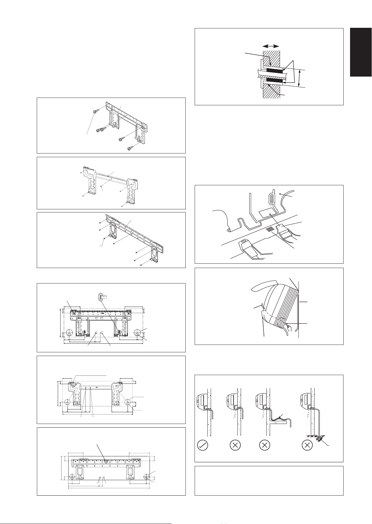
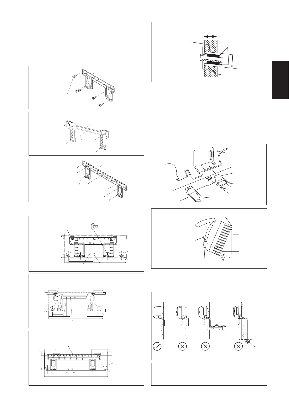
Mounting Installation Plate
Ensure that the wall is strong enough to withstand the weight
of the unit. Otherwise, it is necessary to reinforce the wall
with plates, beams or pillars.
Use the level gauge for horizontal mounting, and fix it with 5
suitable screws for FTXN/FTK 25/35 and 7 suitable screws
for FTXN/FTK 50/60.
In case the rear piping draws out, drill a hole 65mm in
diameter with a cone drill, slightly lower on the outside wall
(see figure).
FTXN 25/35
FTK 25/35
Mounting plate fixing screw
FTK 25/35
(ALTERNATIVE INSTALLATION PLATE)FTXN 25/35
Mounting plate
Mounting plate
Hole with cone drill
Wall embedded pipe
Inside
(Field supply)
Wall hole cover
(Field supply)
Outside
Caulking
Ø 65
Wall embedded pipe
(Field supply)
Mount The Unit Onto The Installation Plate
Hook the indoor unit onto the upper portion of the installation
plate (Engage the two hooks at the rear top of the indoor unit
with the upper edge of the installation plate). Ensure that the
hooks are properly seated on the installation plate by moving
it to the left and right.
How To Attach The Indoor Unit
Hook the claws of the bottom frame to the mounting plate.
How To Remove The Indoor Unit
Push up the marked area (at the lower part of the front
grille) to release the claws.
English
Mounting plate
fixing screw
FTXN 50/60
FTK 50/60
Mounting plate
Mounting plate fixing screw
Recommended Mounting Plate Retention Spots And
Dimensions
FTXN 25/35
FTK 25/35
« Recommended mounting plate retention spots
(5 spots in all)
FTK 25/35
166
288
45.9 42.2
54.5 153.8
263
(ALTERNATIVE INSTALLATION PLATE)FTXN 25/35
Recommended mounting plate retention spots
«
(5 spots in all)
104
30
Use tape measure as shown.
Position the end of a tape measure at
51.9
800
Gas pipe endLiquid pipe end
184
181.7 55.5
All dimensions are in mm
141
Ñ
42.2
Through the wall hole Ø 65mm
45.9
Drain hose position
30
Mounting plate
Clip
Front grille
Bottom frame
Mark (Rear side)
Hand indoor unit’s hook here.
When stripping the ends
of interconnecting wires in
Mounting plate
advance, bind right ends of
wires with insulating tape.
Interconnecting
wires
Wire guide
Water Drainage Piping
The indoor drain pipe must be in a downward gradient for
smooth drainage. Avoid situations that are likely to cause
water to leak.
Water Drainage
288
46
Liquid pipe end
FTXN 50/60
FTK 50/60
«
Recommended mounting plate retention spots
(7 spots in all)
310
153
55 207
61
40
45
Through the wall hole Ø 65mm
52
800
Gas pipe end
46
Drain hose position
56
181
All dimensions are in mm
Water
leaking
Water
leaking
Water
retention
Water
leaking
End
dipped
into
water
Drain
190
91
580
Gas pipe endLiquid pipe end
45
1065
173
61
Through the wall hole
Ø 65mm
40
Drain hose position
48
219
All dimensions are in mm
Correct Wrong
Wrong Wrong
! CAUTION
• Do not install the unit at altitude over 2000m for both
indoor & outdoor.
1-9

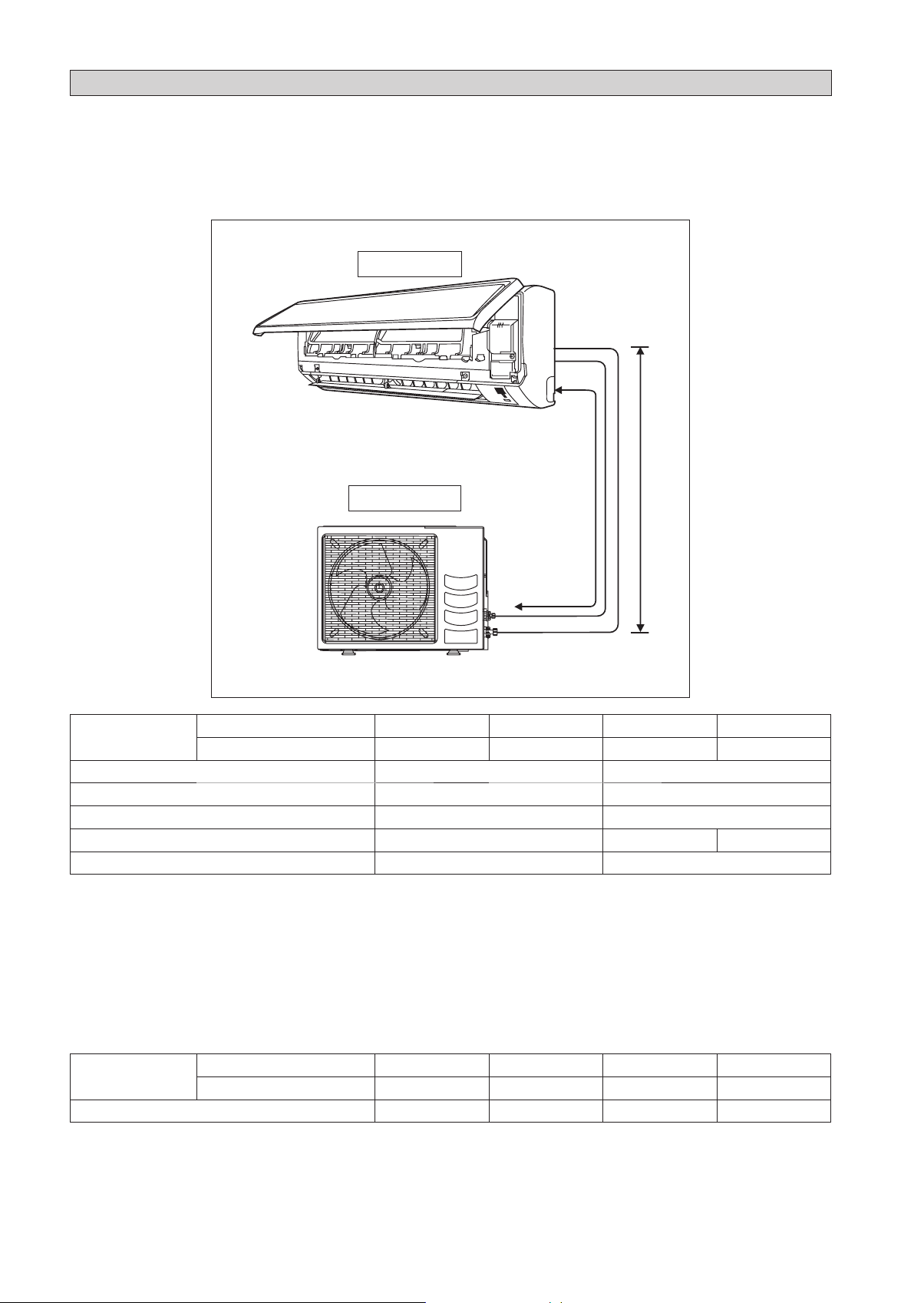
REFRIGERANT PIPING
Allowable Piping Length
If the pipe is too long, both the capacity and reliability of the unit will drop. As the number of bends increases, resistance to
the flow of refrigerant system increases, thus lowering cooling capacity. As a result, the compressor may become defective.
Always choose the shortest path and follow the recommendations as tabulated below:
Indoor unit
LE
Outdoor Unit
Model
Min. Allowable Length (L), m 33
Max. Allowable Length (L), m 20 30
Max. Allowable Elevation (E), m 10 10
Gas Pipe Size, mm/(in) 9.52 (3/8") 12.70 (1/2") 15.88 (5/8")
Liquid Pipe Size, mm/(in) 6.35 (1/4") 6.35 (1/4")
*Be sure to add the proper amount of additional refrigerant. Failure to do so may result in reduced performance.
Remark: The refrigerant pre-charged in the outdoor unit is for piping length up to 7.5m.
Indoor (FTXN/FTK) 25 35 50 60
Outdoor (RXN/RK) 25 35 50 60
Additional Charge
The refrigerant is pre-charged in the outdoor unit. If the piping length is less than 7.5m, then additional charge after vacuuming
is not necessary. If the piping length is more than 7.5m, then use the additional charge value as indicated in the table.
Additional refrigerant charge [g] per additional 1m length as tabulated
Model
Additional charge [g/m] 20 20 20 20
Example:
FTXN25 & RXN25 with 12m piping length, additional piping length is 4.5m. Thus,
Additional charge = 4.5[m] x 20[g/m]
Indoor (FTXN/FTK) 25 35 50 60
Outdoor (RXN/RK) 25 35 50 60
= 90.0[g]
1-10
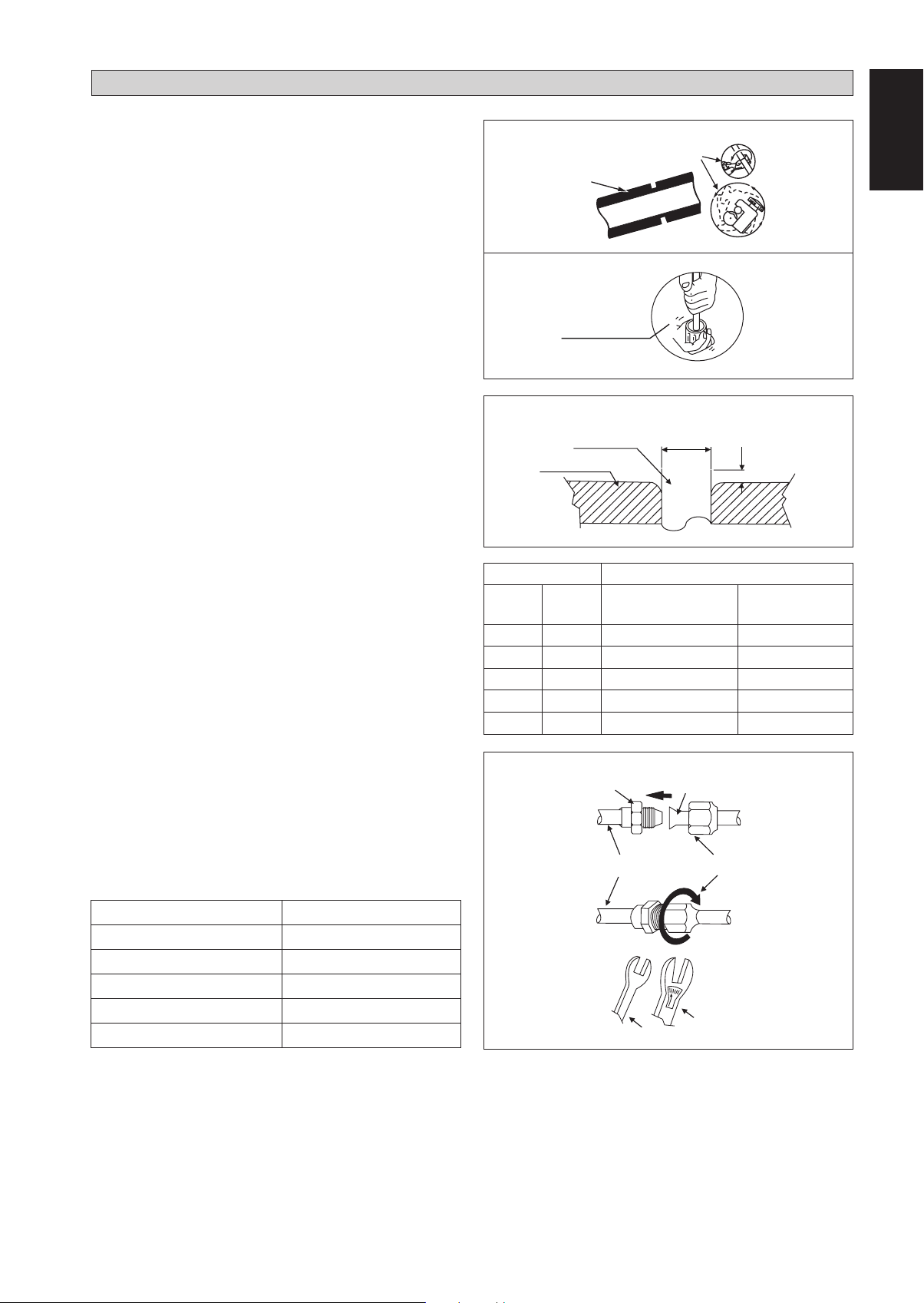
REFRIGERANT PIPING
Piping Works And Flaring Technique
Do not use contaminated or damaged copper tubing. If
•
any piping, evaporator or condenser had been exposed or
had been opened for 15 seconds or more, the system must
be vacuumed. Generally do not remove plastic, rubber
plugs and brass nuts from the valves, fittings, tubing and
coils until it is ready to connect suction or liquid line into
valves or fittings.
If any brazing work is required, ensure that nitrogen gas
•
is passed through coil and joints while the brazing work
is being done. This will eliminate soot formation on the
inside wall of copper tubings.
Cut the pipe stages by stages, advancing the blade of pipe
•
cutter slowly. Extra force and a deep cut will cause more
distortion of pipe and therefore extra burr. See Figure I.
Remove burrs from cut edges of the pipes with remover. See
•
Figure II. Hold the pipe on top position and burr remover
at lower position to prevent metal chips from entering the
pipe. This will avoid unevenness on the flare faces which
will cause gas leak.
Insert the flare nuts, mounted on the connection parts
•
of both the indoor unit and outdoor unit, into the copper
pipes.
The exact length of pipe protruding from the top surface
•
of the swaging block is determined by the flaring tool.
See Figure III.
Fix the pipe firmly on the swaging block. Match the centers
•
of both the swaging block and the flaring punch, then
tighten the flaring punch fully.
The refrigerant pipe connection are insulated by closed
•
cell polyurethane.
Piping Connection To The Units
Align the center of the piping and tighten the flare nut
•
sufficiently with fingers. See Figure IV.
Finally, tighten the flare nut with torque wrench until the
•
wrench clicks.
When tightening the flare nut with the torque wrench,
•
ensure that the tightening direction follows the arrow
indicated on the wrench.
The refrigerant pipe connection are insulated by closed
•
cell polyurethane.
Figure I
Figure II
Figure III
Swaging Block
Cutting Copper Tube
1/4t
Remove Burr
Copper Tube
D
A
Ø Tube, D A (mm)
Inch mm Imperial
(Wing-nut Type)
Rigid
(Clutch Type)
1/4" 6.35 1.3 0.7
3/8" 9.52 1.6 1.0
1/2" 12.70 1.9 1.3
5/8" 15.88 2.2 1.7
3/4" 19.05 2.5 2.0
Figure IV
Flare Joint
Flared Tube
Flare NutIndoor Piping
English
Pipe Size, mm (in) Torque, Nm/(ft-lb)
6.35 (1/4") 18 (13.3)
9.52 (3/8") 42 (31.0)
12.70 (1/2") 55 (40.6)
15.88 (5/8") 65 (48.0)
19.05 (3/4") 78 (57.6)
1-11
Spanner
Torque Wrench
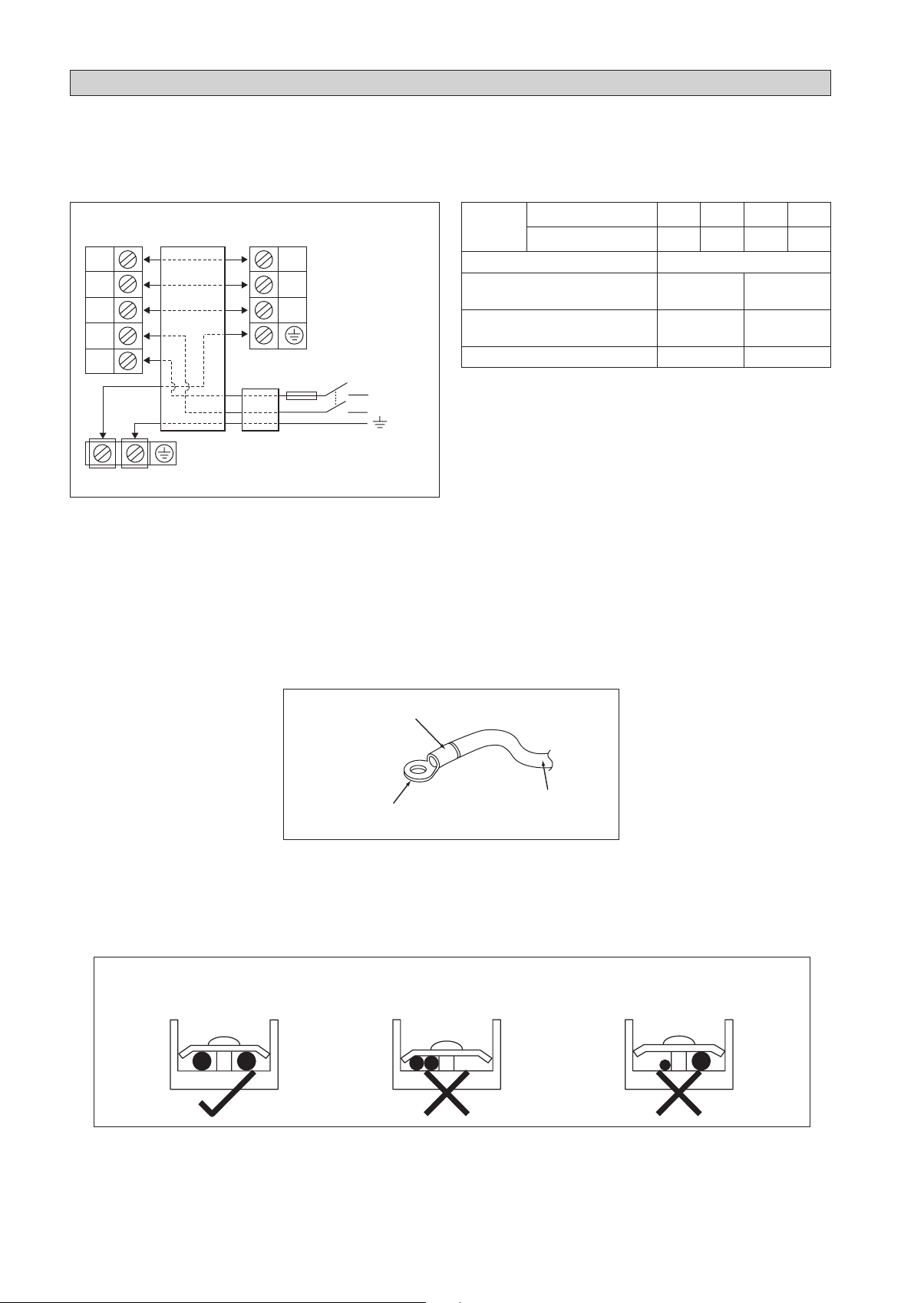
ELECTRICAL WIRING CONNECTION
IMPORTANT : * The figures shown in the table are for information purpose only. They should be checked and selected
to comply with the local/national codes of regulations. This is also subject to the type of installation and
conductors used.
** The appropriate voltage range should be checked with label data on the unit.
Indoor Unit
Terminal Block
1
2
SIG
N
L
All wires must be firmly connected.
•
Make sure all the wire do not touch the refrigerant pipings, compressor or any moving parts.
•
The connecting wire between the indoor unit and the outdoor unit must be clamped by using provided cord anchorage.
•
The power supply cord must be equivalent to H07RN-F which is the minimum requirement.
•
Make sure no external pressure is applied to the terminal connectors and wires.
•
Make sure all the covers are properly fixed to avoid any gap.
•
Use round crimp-style terminal for connecting wires to the power supply terminal block. Connect the wires by matching
•
Interconnection
cable
Outdoor Unit
Terminal Block
1
2
SIG
Power
Supply
Cable
There must be an all pole disconnection
!
in the supply mains with a contact
separation of at least 3mm.
Fuse /
Circuit
Breaker
Main
Switch
L / L1
N / L2
Power
Supply
Model Indoor (FTXN/FTK)
Outdoor (RXN/RK)
Voltage range
Power supply cable size
**
*
mm
Number of conductors
Interconnection cable size
*
mm
Number of conductors
Recommended fuse /circuit breaker rating A 16 20
* If the length of the cable is more than 2m, use cable with bigger size.
25 35 50 60
25 35 50 60
220-240V/~/50Hz +
2
1.5
3
2
1.5
4
!
2.5
3
2.5
4
to the indication on terminal block. (Refer to the wiring diagram attached on the unit).
Attach insulation sleeve
Electric wire
Round crimp-style terminal
Used the correct screwdriver for terminal screws tightening. Unsuitable screwdrivers can damage the screw head.
•
Over tightening can damage the terminal screws.
•
Do not connect wire of different gauge to same terminal.
•
Keep wiring in an orderly manner. Prevent the wiring from obstructing other parts and the terminal box cover.
•
Connect wires of the
same gauge to both side.
Do not connect wires of the
same gauge to one side.
Do not connect wires
of different gauges.
1-12
SPECIAL PRECAUTIONS WHEN DEALING WITH R410A UNIT
R410A is a new HFC refrigerant which does not damage the
ozone layer. The working pressure of this new refrigerant is
1.6 times higher than conventional refrigerant (R22), thus
proper installation/servicing is essential.
Never use refrigerant other than R410A in an air conditioner
•
which is designed to operate with R410A.
POE or PVE oil is used as lubricant for R410A compressor,
•
which is different from the mineral oil used for R22
compressor. During installation or servicing, extra precaution
must be taken not to expose the R410A system too long
to moist air. Residual POE or PVE oil in the piping and
components can absorb moisture from the air.
To prevent mischarging, the diameter of the service port
•
Use tools and materials exclusively for refrigerant R410A.
•
Tools exclusively for R410A are manifold valve, charging
hose, pressure gauge, gas leak detector, flare tools, torque
wrench, vacuum pump and refrigerant cylinder.
As an R410A air conditioner incurs higher pressure
•
than R22 units, it is essential to choose the copper pipes
correctly. Never use copper pipes thinner than 0.8mm even
though they are available in the market.
If the refrigerant gas leakage occurs during installation/
•
servicing, be sure to ventilate fully. If the refrigerant gas
comes into contact with fire, a poisonous gas may occur.
When installing or removing an air conditioner, do not
•
allow air or moisture to remain in the refrigerant cycle.
on the flare valve is different from that of R22.
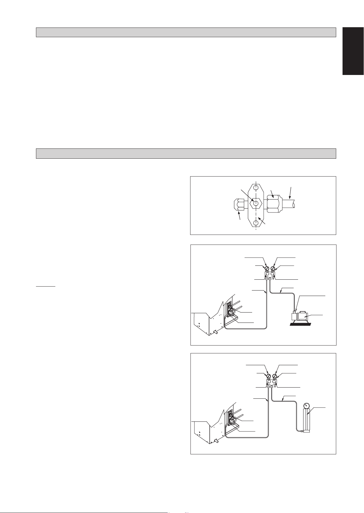
VACUUMING AND CHARGING
Vacuuming is necessary to eliminate all moisture and air from the system.
Vacuuming The Piping And The Indoor Unit
Except for the outdoor unit which is pre-charged with
refrigerant, the indoor unit and the refrigerant connection
pipes must be air-purged because the air containing moisture
that remains in the refrigerant cycle may cause malfunction
of the compressor.
Remove the caps from the valve and the service port.
•
Connect the center of the charging gauge to the vacuum
•
pump.
Connect the charging gauge to the service port of the 3-way
•
valve.
Start the vacuum pump. Evacuate for approximately 30
•
minutes. The evacuation time varies with different vacuum
pump capacity. Confirm that the charging gauge needle has
moved towards -760mmHg.
Caution
If the gauge needle does not move to -760mmHg, be sure to
•
check for gas leaks (using the refrigerant detector) at flare
type connection of the indoor and outdoor unit and repair
the leak before proceeding to the next step.
Close the valve of the changing gauge and stop the vacuum
•
pump.
On the outdoor unit, open the suction valve (3 way) and
•
liquid valve (2 way) (in anti-clockwise direction) with 4mm
key for hexagon sacked screw.
Allen key
Service Port
LOW PRESSURE GAUGE
-760mmHg
HANDLE LO
CHARGE HOSE
LIQUID VALVE
GAS VALVE
(3-WAY)
Flare nut
Outdoor Unit 3 ways valve
Refrigerant Piping
HIGH PRESSURE GAUGE
GAUGE MANIFOLD
HANDLE HI (ALWAYS CLOSED)
CHARGE HOSE
VACUUM PUMP
ADAPTER FOR
COUNTER FLOW
PREVENTION
CHECK VALVE
CONFIGURATION OF AIR
PURGE BY CHARGING
English
Charge Operation
This operation must be done by using a gas cylinder and a
precise weighing machine. The additional charge is topped-up
into the outdoor unit using the suction valve via the service
port.
Remove the service port cap.
•
Connect the low pressure side of the charging gauge to the
•
suction service port center of the cylinder tank and close
the high pressure side of the gauge. Purge the air from the
service hose.
Start the air conditioner unit.
•
Open the gas cylinder and low pressure charging valve.
•
When the required refrigerant quantity is pumped into
•
the unit, close the low pressure side and the gas cylinder
valve.
Disconnect the service hose from service port. Put back
•
the service port cap.
1-13
LOW PRESSURE GAUGE
-760mmHg
HANDLE LO
CHARGE HOSE
LIQUID VALVE
GAS VALVE
(3-WAY)
HIGH PRESSURE GAUGE
GAUGE MANIFOLD
HANDLE HI (ALWAYS CLOSED)
CHARGE HOSE
CHECK VALVE
CONFIGURATION OF AIR
PURGE BY CHARGING

INDICATOR LIGHTS
IR Signal Receiver
When an infrared remote control operating signal has been
transmitted, the signal receiver on the indoor unit will respond
as below to confi rm acceptance of the signal transmission.
ON to OFF 1 Long Beep
OFF to ON
2 Short Beep
Pump down / Cool force on
Others 1 Short Beep
IR Receiver
Cooling Unit/Heat Pump Unit
The table shows the LED indicator lights for the air conditioner
LED Indicator Lights for Cooling Unit/Heat Pump
Unit
unit under normal operation and fault conditions. The LED
indicator lights are located at the side of the air conditioner
unit.
The heat pump units are equipped with an “auto” mode
sensor whereby it will provide reasonable room temperature
by switching automatically to either “cool” or “heat” mode
according to the temperature set by the user.
ON/OFF
IR Receiver
Cool/Heat
Timer
Sleep
ON/OFF switch
LED Indicator Lights: Normal Operation And Fault Conditions For Cooling/Heat Pump Unit
COOL/HEAT
(GREEN/RED)
GREEN
Operation
Cool mode
ON
RED
RED
GREEN
GREEN
GREEN
RED
GREEN
Heat mode
Auto mode in Heating operation
Auto mode in Cooling operation
Timer on
Sleep mode on
Fan mode on
Dry mode on
Defrost operation
Unit error
Blinking
1-14
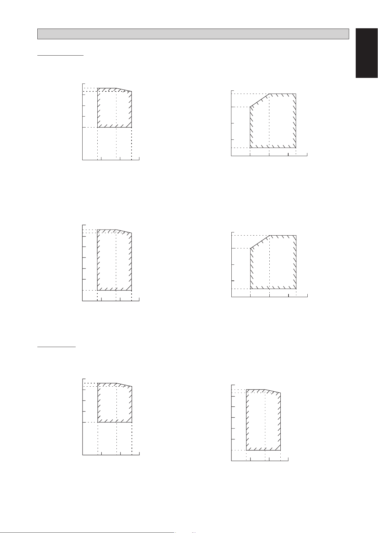
Heat Pump Model
OPERATING RANGE
Model: FTXN 25/35 RXN 25/35
COOLING HEATING
50
46
43
40
30
20
10
OUTDOOR TEMP (˚CDB)
0
INDOOR TEMP (˚CWB)
Model: FTXN 50/60 RXN 50/60
50
46
43
40
30
20
10
COOLING HEATING
252314 15 19 2010
DB: Dry bulb WB: Wet bulb
20
18
10
0
-10
-15
OUTDOOR TEMP (˚CWB)
-20
20
18
10
0
English
2015 03725201
INDOOR TEMP (˚CDB)
0
-10
OUTDOOR TEMP (˚CDB)
-20
10 14 15 19 20 23 25
INDOOR TEMP (˚CWB)
Cooling Model
Model: FTK 25/35 RK 25/35
50
46
43
40
30
20
10
OUTDOOR TEMP (˚CDB)
0
COOLING
INDOOR TEMP (˚CWB)
DB: Dry bulb WB: Wet bulb
Model: FTK 50/60 RK 50/60
252314 15 19 2010
-10
-15
OUTDOOR TEMP (˚CWB)
-20
INDOOR TEMP (˚CDB)
COOLING
50
46
43
40
30
20
10
0
OUTDOOR TEMP (˚CDB)
-10
-20
10 14 15 19 20 23 25
INDOOR TEMP (˚CWB)
2015 03725201
DB: Dry bulb WB: Wet bulb
1-15
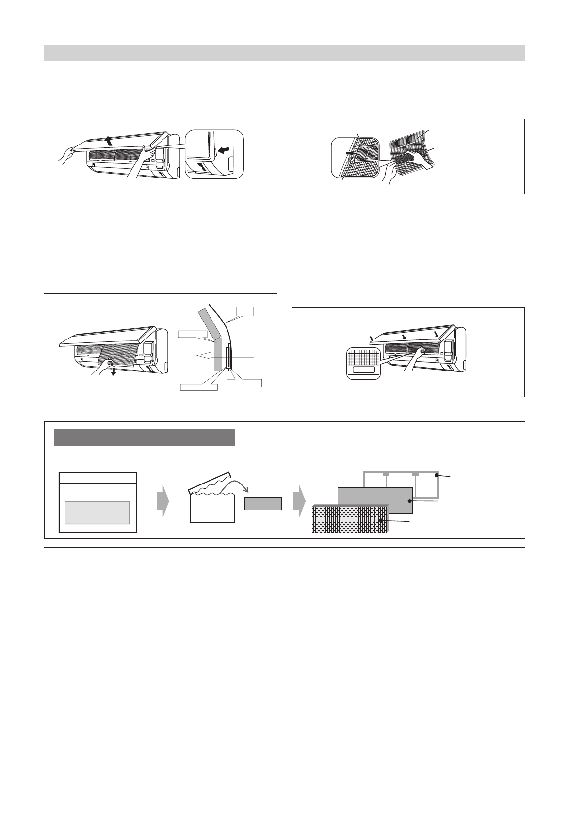
AIR FILTER
1. Open the front panel.
• Hold the panel at the recesses on the main unit
(2 recesses on right and left sides) and lift it until it
stops.
Recess on
main unit
2. Pull out the air filters.
• Push a little upwards the tab at the center of each air
filter, then pull it down.
3. Take off the Bio filter with bacteriostatic,
virustatic functions.
• Hold the recessed parts of the frame and unhook the
four claws.
Titanium Apatite Filter (Bio Filter)
Attached Concept
Heat exchanger
Air Filter
4. Clean or replace each filter.
See figure.
• When shaking off remaining water, do not wring the
filter.
Filter frame
Tab
Air filter
Bio filter with
bacteriostatic,
virustatic functions
5. Set the air filter and Bio filter with bacteriostatic,
virustatic functions as they were and close the
front panel.
• Insert claws of the filters into slots of the front panel.
Close the front panel slowly and push the panel at the
3 points. (1 on each side and 1 in the middle.)
• The air filter and Bio filter with bacteriostatic,
virustatic functions have a symmetrical form in the
horizontal direction.
FRONT
Bio Filter attached part
Titanium Apatite Filter
* Bio Filter and Titanium Apatite Filter are optional accessories.
Installation Procedure for Bio Filter
Bio Filter packs in a
hermetically-sealed bag.
Take it out
at the time of installation.
Slip the Filter in between Filter frame and
Titanium Apatite Filter.
Filter frame
Bio Filter
Titanium Apatite Filter
! CAUTION
• Please use this Bio Filter during dry season such as winter.
• Storage, handling and disposal methods.
• The lifetime of this Bio Filter is about a year after opening.
• In case you do not use this Bio Filter right away, please don’t place the Bio Filter in any place where it will be
subjected to direct sunlight, high temperatures and/or high humidity.
• There can be slight differences between Bio Filter color because of the manufacturing reasons, there is no effect
on the unit performance.
• Please open this bag right before you use it. Bio Filter should remain unopened and sealed in its packaging until
right before usage. (It may cause performance deterioration or quality change.)
• To avoid danger of suffocation and any unexpected accident, please dispose the plastic bag immediately after you
remove the Bio Filter. Keep out of reach of babies and children.
• If you keep this Bio Filter for a long time, please keep it unopened and store in a cool place avoiding direct
sunlight.
• Please dispose the old Bio Filter as nonflammable garbage after use.
• Operation with dirty filters:
(1) cannot deodorize the air. (3) results in poor heating or cooling.
(2) cannot clean the air. (4) may cause odour.
• To order Bio Filter, contact the service shop where you bought the air conditioner.
1-16
SERVICE AND MAINTENANCE
Service Parts Maintenance Procedures Period
Indoor air filter Remove any dust adhering to the filter by using a vacuum cleaner or wash
1.
in lukewarm water (below 40°C/104°F) with a neutral cleaning detergent.
Rinse the filter well and dry before placing it back onto the unit.
2.
Do not use gasoline, volatile substances or chemicals to clean the filter.
3.
At least once every
2 weeks.
More frequently if
necessary.
English
Indoor unit Clean any dirt or dust on the grille or panel by wiping it with a soft cloth
1.
soaked in lukewarm water (below 40°C/104°F) and a neutral detergent
solution.
Do not use gasoline, volatile substances or chemicals to clean the indoor
2.
unit.
At least once every
2 weeks.
More frequently if
necessary.
! CAUTION
• Avoid direct contact of any coil treatment cleaners on plastic part. This may cause plastic part to deform as a result
of chemical reaction.
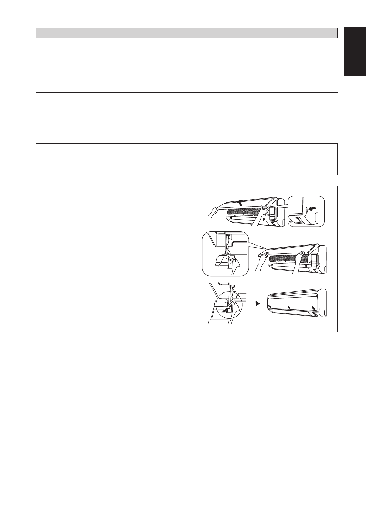
Open the front panel.
1.
Hold the panel at the recesses on the main unit
•
(2 recesses on right and left sides) and lift it until it
stops.
Remove the front panel.
2.
While lifting the front panel further, slide it to the right
•
and pull it to the front side. The left rotating shaft is
detached. Slide the right rotating shaft to the left and
pull it to the front side to remove it.
Attach the front panel.
3.
Align the right and left rotating shafts of the front panel
•
with the grooves and push them all the way in.
Gently close the front panel. (Push both ends and the
•
center on the front panel.)
Rotating
shaft
Recess on
main unit
1-17
! CAUTION
•
Don’t touch the metal parts of the indoor unit. It may cause an injury.
•
When removing or attaching the front panel, support the panel securely with hand to prevent it from falling.
•
For cleaning, do not use hot water above 40°C, benzine, gasoline, thinner, nor other volatile oils, polishing
compound, scrubbing brushes, nor other hand stuff.
After cleaning, make sure that the front panel is securely fixed.
•
When The Unit Is Not To Be Used For An Extended Long Period Of Time
Operate the unit for 2 hours with
the following setting.
Operating mode : cool
Temperature : 30°C/86°F
Remove the power plug.
If you are using an
independent electric
circuit for your unit, cut
off the circuit.
Remove the batteries in
the remote control.
TROUBLESHOOTING
For any enquiries on spare part, please contact your authorized dealer. When any malfunction of the air
conditioner unit is noted, immediately switch off the power supply to the unit. Check the following fault
conditions and causes for some simple troubleshooting tips.
Fault Causes / Action
The compressor does not operate 3 minutes after the air
1. Protection against frequent starting. Wait for 3 to 4 minutes
conditioner unit is started.
The air conditioner unit does not operate.2. Power failure, or the fuse needs to be replaced.
–
for the compressor to start operating.
–
The power plug is disconnected.
–
It is possible that your delay timer has been set
–
incorrectly.
If the fault persist after all these verifications, please
–
contact the air conditioner unit installer.
The air flow is too low.3. The air filter is dirty.
Discharge air flow has bad odour.4. Odours may be caused by cigarettes, smoke particles,
Condensation on the front air grille of the indoor unit.5. This is caused by air humidity after an extended long
Water flowing out from the air conditioner unit.6. Switch off unit and call dealer.–
–
The doors or windows are open.
–
The air suction and discharge are clogged.
–
The regulated temperature is not high enough.
–
–
perfume etc. which might have adhered onto the coil.
–
period of operation.
The set temperature is too low, increase the temperature
–
setting and operate the unit at high fan speed.
If the fault persists, please call your local dealer / serviceman.
1-18
DISEGNI E DIMENSIONIS
Unità Interna [FTXN/FTK]
IL SEGNO MOSTRA LA DIREZIONE DEI TUBI
A
SINISTRA
B
IN BASSO
DIETRO DIETRO
VISTA DALL’ALTO
IN BASSO
FERITOIA DI
AERAZIONE
VITI INSERITE NELLA GRIGLIA
FRONTALE (ALL’INTERNO)
VISTA FRONTALE
DESTRA
RICEVITORE DI
SEGNALE
UNITÀ INTERNA
INTERRUTTORE ON/OFF
TEMPERATURA AMBIENTE TERMOSTATO
(ALL’INTERNO)
B
VISTA LATERALE
NOTA: IN BASE ALLA EFFETTIVA INSTALLAZIONE DESIGN DELLA PIASTRA DELL'UNITÀ PER
L'INSTALLAZIONE A 25/35 DIMENSIONE PIASTRA RIFERIMENTO A PAGINA 1 &2.
Italiano
C
PIASTRA
MORSETTIERA
CONTERMINALE
A TERRA
Traduzione delle istruzioni originali
«
Punti di ritenzione raccomandati per la piastra di
montaggio (5 punti in tutto)
D
F
B
G
H
Dimensioni
Modello
25/35
J
Estremità del tubo del liquido
ABCDE FGHI JKLM
800 288 212 166 184 42 46 55 56 154 182 263 52
Utilizzare misura di nastro, come mostrato.
Posizione l’estremità di una misura di nastro
L
M
A
Estremità del tubo del gas
LASTRA DI INSTALLAZIONE 25/35
Ñ
E
F
Foro nel muro
di Ø 65mm
G
K
I
Posizione del
tubo di scarico
2-1
Tutte le dimensioni sono in mm
«
Punti di ritenzione raccomandati per la piastra di montaggio
(5 punti in tutto)
D
E
Modello
25/35
F
B
G
Estremità del tubo del liquido
Dimensioni
F
Foro nel muro di Ø 65mm
G
JH
ML
IN ALTERNATIVA PIASTRA DI INSTALLAZIONE 25/35
A
Estremità del tubo del gas
Posizione del tubo di scarico
IK
Tutte le dimensioni sono in mm
ABCDE FGHI JKLM
800 288 212 104 141 30 46 55 56 153 181 207 52
«
Punti di ritenzione raccomandati per la piastra di montaggio
(7 punti in tutto)
D
F
B
G
H
Dimensioni
Modello
50/60
Estremità del tubo del liquido
J
L
M
ABCDE FGH I JKLM
1065 310 229 190 173 61 40 45 48 91 219 580 45
Estremità del tubo del gas
A
LASTRA DI INSTALLAZIONE 50/60
E
F
Foro nel muro di Ø 65mm
G
K
I
Posizione del tubo di scarico
Tutte le dimensioni sono in mm
2-2
Unità Esterna [RXN/RK]
Tutte le dimensioni sono in mm
J
G
HI
OP
N
Q
Modello
Dimensioni
EF
2,0
A
B
ABCDE FGH I JKLMNOPQ
CD
KL
M
25/35 550 658 51 11 273 16 14 470 96 93 94 60 14 133 8 10 299
KLL
N
M
Q
Tutte le dimensioni sono in mm
Italiano
T
C
GH
I
J
Modello
3,0
B
P
Dimensioni
A
O
V
D
U
N
F
E
S
R
ABCDE FGHI JKLMN
50/60 855 730 328 520 179 46 93 149 101 113 603 126 164 15
Dimensioni
Modello
O P Q R S TUV
50/60 34 23 362 73 75 8 67 7
2-3
MANUALE D’INSTALLAZIONE
Il presente manuale descrive come procedere all’installazione del condizionatore per assicurarne il corretto funzionamento in condizioni di sicurezza.
Degli adattamenti possono rivelarsi necessari per rispondere a particolari esigenze locali.
Prima di utilizzare il condizionatore, leggere attentamente le presenti istruzioni. Conservarle per ogni evenienza futura.
Questo apparecchio è destinato all’uso da parte di persone esperte o formate in negozi, nell’industria leggera o in aziende agricola o all’uso commerciale
da parte di persone non addette.
Il presente apparecchio non è destinato all’uso da parte di persone, inclusi bambini, con ridotte capacità fi siche, sensoriali o mentali, o senza la dovuta
esperienza e conoscenza, a meno che non vengano poste sotto la supervisione di una persona responsabile della loro sicurezza o che tale persona fornisca
loro le istruzioni per l’uso dell’apparecchio.
Tenere i bambini sotto la supervisione di un adulto per evitare che giochino con l’apparecchio.
NORME DI SICUREZZA
! AVVERTENZA ! CAUTELA
L’installazione e la manutenzione devono essere eseguite da personale
•
qualificato, competente in questo genere di apparecchi e al corrente delle
leggi e regolamenti in vigore.
Tutti gli allacciamenti elettrici devono essere eseguiti conformemente
•
alla regolamentazione elettrica in vigore.
Prima di procedere agli allacciamenti secondo lo schema elettrico
•
presentato più avanti, accertarsi che il voltaggio dell’apparecchio
corrisponda a quello della rete.
Dotare il condizionatore di una presa di TERRA al fine di prevenire i
•
rischi originati da eventuali deficienze del sistema di isolamento.
I fili elettrici non devono toccare né i condotti dell’acqua, né gli organi
•
rotanti dei motori del ventilatore.
Prima di installare il condizionatore o di procedere ad interventi di
•
manutenzione, accertarsi che sia spento (OFF).
Togliete sempre la corrente prima di effettuare la manutenzione del
•
condizionatore.
NON rimuovere il cavo di alimentazione quando il condizionatore è
•
acceso. Questo può causare seri shock elettrici e pericolo d’incendio.
Mantenere l’unità interna e quella esterna, il cavo di alimentazione e
•
il cablaggio di trasmissione ad almeno 1m di distanza da TV e radio,
per evitare immagini distorte e scariche statiche. {A seconda del tipo e
sorgente di onde elettriche, si possono sentire scariche statiche anche a
più di 1m di distanza}.
Durante l’installazione, verifi care accuratamente i punti seguenti.
Non procedere all’installazione in luoghi dove possano verifi carsi
•
fughe di gas.
Pericolo d’incendio in caso di fughe o di concentrazioni di gas
intorno al condizionatore.
Verificare che i condotti di drenaggio siano stati correttamente
•
installati.
Un’installazione incorretta può causare delle perdite d’acqua e
danneggiare il mobilio.
Non sovraccaricare il condizionatore.
•
L’apparecchio è precaricato in fabbrica.
Qualsiasi sovraccarico provoca una sovracorrente e può danneggiare
il compressore.
Dopo l’installazione o gli interventi di manutenzione accertarsi di
•
rimettere a posto il pannello di chiusura.
Una difettosa chiusura del pannello è causa di rumori durante il
funzionamento.
I bordi affi lati e le superfi ci della serpentina sono possibili aree che
•
possono causare pericolo di lesioni. Evitare di entrare in contatto
con tali aree.
Prima di spegnere l’apparecchio, impostare l’interruttore ON/OFF
•
del telecomando sulla posizione “OFF” in modo da evitare l’apertura
nociva dell’unità. In caso contrario, le ventole dell’unità iniziano a ruotare
automaticamente quando si riaccende l’apparecchio, causando pericoli di
lesioni al personale di servizio ed agli utenti.
Non installare le unità sul vano della porta o nelle sue vicinanze.
•
Non mettere in funzione apparecchi per il riscaldamento troppo vicini
•
al condizionatore d’aria o non utilizzare l’unità in un ambiente in cui
sono presenti olio minerale o vapori da olio, ciò potrebbe provocare la
fusione o la deformazione della plastica a seguito del calore eccessivo
o di una reazione chimica.
Quando l’unità è utilizzata in cucina, tenere la farina lontana in modo
•
da evitare che l’unità la aspiri.
Questa unità non è idonea all’utilizzo in stabilimenti dove sono
•
presenti nebbie di olio da taglio o polveri metalliche o dove c’è una
forte oscillazione di tensione.
Non installare le unità in aree quali le sorgenti calde o le raffi nerie
•
petrolifere in cui è presente gas solforoso.
Accertarsi che i colori dei fi li dell’unità esterna corrispondano ai
•
contrassegni dei morsetti dell’unità interna.
IMPORTANTE: NON INSTALLARE O UTILIZZARE IL
•
CONDIZIONATORE D’ARIA IN UNA ZONA LAVANDERIA.
Non usare fi li congiunti e intrecciati per l’alimentazione in ingresso.
•
L’apparecchio non è destinato all’uso in un ambiente potenzialmente
•
esplosivo.
Specifiche di smaltimento
AVVISO
Il climatizzatore è contrassegnato con questo simbolo, Ciò significa che i prodotti elettrici ed elettronici non possono essere smaltiti insieme ai rifiuti
domestici non differenziati.
Non cercare di demolire il sistema da soli: la demolizione del sistema di condizionamento, nonché il recupero del refrigerante, dell’olio e di qualsiasi
altra parte devono essere eseguiti da un installatore qualificato in conformità alla legislazione locale e nazionale vigente in materia.
I climatizzatori devono essere trattati presso una struttura specializzata nel riutilizzo, riciclaggio e recupero dei materiali. Il corretto smaltimento del prodotto
eviterà le possibili conseguenze negative all’ambiente e alla salute dell’uomo. Per maggiori informazioni contattare l’installatore o le autorità locali.
Le batterie devono essere tolte dal telecomando e smaltite separatamente conformemente alla legislazione locale e nazionale vigente in materia.
2-4
IMPORTANTE
Informazioni importanti sul refrigerante utilizzato
Questo prodotto contiene gas fluorinati ad effetto serra inclusi nel protocollo di Kyoto.
Non liberare tali gas nell’atmosfera.
Tipo di refrigerante: R410A
Valore GWP
(1)
GWP = Global Warming Potential (Potenziale Di Riscaldamento Globale)
Compilare con inchiostro indelebile,
¢
1 la carica di refrigerante di fabbrica del prodotto,
¢
2 la quantità di refrigerante aggiuntiva nel campo e
¢
1 + 2 la carica di refrigerante totale
sull’etichetta di carica del refrigerante fornita con il prodotto.
L’etichetta compilata deve essere collocata in prossimità della porta di carica del prodotto (ad esempio, all’interno del coperchio
di ispezione).
(1)
: 1975
1
carica di refrigerante di fabbrica del prodotto:
vedi targhetta con il nome dell’unità
quantità di refrigerante aggiuntiva nel campo
2
carica di refrigerante totale
3
contiene gas fluorurati ad effetto serra disciplinati dal Protocollo di Kyoto
4
(2)
Italiano
unità esterna
5
cilindro del refrigerante e collettore di carica
6
(2)
Se sono presenti sistemi con più unità interne, applicare una sola etichetta*, indicante la carica totale di refrigerante eseguita
in fabbrica di tutte le unità interne collegate al sistema refrigerante.
È possibile che siano necessarie ispezioni periodiche per controllare eventuali perdite di refrigerante secondo le normative
locali e/o europee. Per informazioni più dettagliate, contattare il rivenditore locale.
* sull’unità esterna
2-5
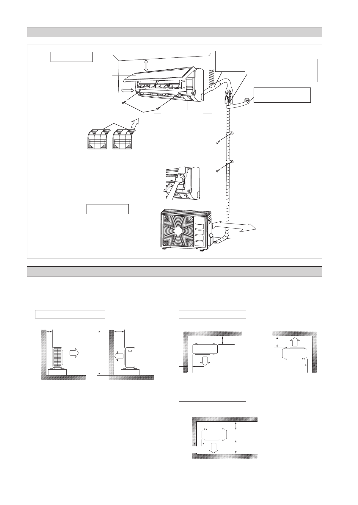
DIAGRAMMA PER L’INSTALLAZIONE
Unità Interna
Pannello anteriore
50mm o più dalle pareti
(su entrambi i lati)
Filtro aria
Unità Esterna
M4 x 12L
30mm o più dal soffitto
Sportellino di manutenzione
Apertura del coperchio di servizio
ó
Il coperchio di servizio può essere
aperto/chiuso.
Metodo di apertura
ó
1) Rimuovere le viti del coperchio
di servizio.
2) Estrarre il coperchio di accesso
per assistenza tecnica spostandolo
verso il basso e in diagonale, nella
direzione della freccia.
3) Tirare verso il basso.
Stuccare lo
spazio del foro
del tubocon
stucco da legno.
500mm dalla parete
Tagliare il tubo di isolamento termico a
una lunghezza appropriata e avvolgerlo
con nastro, accertandosi che non ci siano
buchi nella linea di taglio del tubo di
isolamento.
Avvolgere il tubo di isolamento
da cima a fondo con nastro di
finitura.
INSTALLAZIONE DELL’UNITÀ ESTERNA (RXN/RK 25/35)
Se c’è una parete o un altro ostacolo nel percorso dell’ingresso dell’aria dell’unità esterna o nell’uscita dell’aria di scarico,
•
seguire le linee guida per l’installazione sotto.
Per i moduli di installazione di cui sotto, l’altezza della parete sul lato di scarico dovrebbe essere pari o inferiore a
•
1200mm.
Un lato rivolto alla parete
Oltre 50
1200 o
di meno
Vista laterale
Oltre 100
Due lati rivolti alla parete
Oltre 100
Oltre 50
Tre lati rivolti alla parete
Oltre 150
Oltre 50
Vista superiore
Oltre 150
2-6
Oltre 50
Oltre 300
Vista superiore
Unità: mm
Lavoro di drenaggio. (Solo Per Le Versioni In Pompa Di Calore)
Usare il maschio di spurgo per il drenaggio.
1)
Se la bocchetta di drenaggio è coperta da una base di montaggio o dal
2)
pavimento, posizionare ulteriori piedini ad almeno 30mm d’altezza sotto
le basi dell’unità esterna.
Nelle aree fredde, non usare un tubo flessibile di scarico con l’unità
3)
esterna. (Altrimenti, l’acqua di scarico potrebbe congelarsi, danneggiando
le prestazioni di riscaldamento.)
INSTALLAZIONE DELL’UNITÀ ESTERNA ((RXN/RK 50/60)
Foro acqua di drenaggio
Struttura in basso
Maschio di spurgo
Tubo flessibile (disponibile in commercio,
diam. interno 16mm)
Italiano
L’unità esterna deve essere installata in modo tale da prevenire
ostruzioni al normale deflusso dell’aria e che la circolazione
dell’aria di scarico sia la più ampia possibile. Rispettare,
nell’installazione le distanze di sicurezza sotto indicate.
Selezionare il luogo più freddo possibile in cui la temperatura
dell’aria immessa non sia superiore alla temperatura dell’aria
esterna (Fare riferimento alla gamma operativa).
Distanze di rispetto/sicurezza
Dimensioni
ABCD
Distanza minima, mm 300 1000 300 500
Nota: Se esistono ostacoli di più di 2m di altezza o una qualsiasi
ostruzione al di sopra dell’apparecchiatura, aumentare le distanze
sopra indicate.
Eliminazione Acqua Di Condensa Dell’Unità Esterna
(Solo Per Le Versioni In Pompa Di Calore)
Ci sono 2 fori alla base dell’unità esterna per garantire
•
la fuoriuscita dell’acqua. Inserire il raccordo a gomito in
uno del 2 fori.
Per installare il raccordo a gomito, effettuare le seguenti
•
operazioni: prima inserire una parte del raccordo all’interno
del foro (Parte A). Quindi tirare che tra la tubazione e la
base dell’unità ci sia una fondare saldamente. Assicorarsi
che tra la tubazione e la base dell’unità ci sia una perfetta
aderenza.
Se l’unità esterna è installata in amblenti rolto freddi,
•
l’acqua di condensa potrebbe gecare du’interno della base.
Per evitario, rimuovere il tappo presente nella base per
facilitare il deflusso dell’acqua.
Ostacolo
C
Ostacolo
Aria di ritorno
A
Aria di ritorno
TAP PO
B
Ostacolo
Aria Di Scarico
D
Ostacolo
Pannello Di Servizio
2-7
A
BASE
RACCORDO A GOMITO
RACCORDO A GOMITO
Rimuovere la
copertura laterale
per effettuare i
collegamenti elettrici e
frigoriferi
SPINGERE E TIRARE
VERSO L’ALTO
INSTALLAZIONE DELL’UNITÀ INTERNA
L’unità interna deve essere installata in modo tale da evitare
corto circuito l’aria fredda scaricata con l’aria calda di ritorno.
Si prega di seguire il gioco installazione mostrata in figura.
Installare l’unità interna in modo che non si trovi ad ess ere
direttamente esposta ai raggi del sole o in prossimità di porte
e finestre. Questa disposizione è la migliore anche per le
tubazioni e il sistema di drenaggio.
Flusso d’aria
(All’interno)
min. 30
(Spazio per le
prestazioni)
min. 50
(Spazio per la
manutenzione)
Spazio necessario
Tutte le dimensioni sono in mm
min. 50
(Spazio per la
manutenzione)
Le tubazioni del refrigerante possono essere collegate
in differenti modi (lato posteriore destro o sinistro)
utilizzando i fori predisposti sul rivestimento esterno.
Piegare accuratamente i tubi nel verso richiesto per condurli al
foro appropriato. Per far fuoriuscire il lato e la parte posteriore,
tenere il fondo del tubo e posizionarlo nella direzione richiesta.
Utilizzado del nastro adesivo, fissarve quindi insieme il tubo
di drenaggio.
Tubo laterale destro, posteriore destro o in basso a destra
Tubazione sul lato destro
Rimuovere il coperchio dell’attacco
del tubo in questo punto, in caso di
tubazione sul lato destro
Rimuovere il coperchio
dell’attacco del tubo in questo
punto, in caso di tubazione sul lato
destro inferiore
Tubazione sul
latodestro inferiore
Tubazione sul lato destro
posteriore
Legare insieme il tubo di
raffreddamento e il tubo
flessibile di scarico con
nastro isolante.
Tubo laterale sinistro, posteriore sinistro o in basso a
sinistra
Rimuovere il coperchio
dell’attacco del tubo in
questo punto, in caso di
tubazione sul lato sinistro
Tubazione sul lato
Rimuovere il coperchio dell’attacco
del tubo in questo punto, in caso di
tubazione sul lato sinistro inferiore
Tubazione sul lato sinistro inferiore
sinistro
Tubazione sul lato
sinistro posteriore
2-8
Montaggio Della Staffa Di Supporto
Accertarsi della capacità di tenuta della parete. Se il muro non è in grado di sopportare
il peso dell’apparecchio, rinforzarlo con delle piastre o dei pilastrini di sostegno.
Usare un indicatore di livello per il montaggio orizzontale e eseguire l’installazione con 5
viti adatte al modello FTXN/FTK 25/35 e 7 viti adatte al modello FTXN/FTK 50/60.
Nel caso in cui le tubazioni posteriori fuoriescano, praticare sul muro un foro di 65mm
di diametro servendosi di una perforatrice a cono. Il foro deve presentare all’esterno
una leggera inclinatura verso il basso (veder figura).
FTXN 25/35
FTK 25/35
Piastra di montaggio
Foro Con Perforatrice A Cono
Interno
Tubo incassato nel muro
(A fornitura locale)
Coperchio per il foro nel muro
(A fornitura locale)
Esterno
Stuccatura
Ø 65
Tubo incassato nel muro
(A fornitura locale)
Vite di fissaggio della
piastra d’installazione
FTXN 25/35
FTK 25/35
FTXN 50/60
FTK 50/60
(IN ALTERNATIVA PIASTRA DI INSTALLAZIONE)
Piastra di montaggio
Vite di fissaggio della
piastra d’installazione
Piastra di montaggio
Vite di fissaggio della
piastra d’installazione
Punti Di Fissaggio Della Piastra Di Montaggio E
Dimensioni Raccomandate
FTXN 25/35
FTK 25/35
FTXN 25/35
FTK 25/35
Estremità del tubo del liquido
FTXN 50/60
FTK 50/60
« Punti di ritenzione raccomandati per la
piastra di montaggio (5 punti in tutto)
166
288
45,9 42,2
54,5 153,8
263
Utilizzare misura di nastro, come mostrato.
Posizione l’estremità di una misura di nastro
51,9
800
Estremità del tubo del gasEstremità del tubo del liquido
Tutte le dimensioni sono in mm
(IN ALTERNATIVA PIASTRA DI INSTALLAZIONE)
« Punti di ritenzione raccomandati per la piastra di montaggio
288
30
46
55 207
104
153
(5 punti in tutto)
52
800
Estremità del tubo del gas
141
56
181
Tutte le dimensioni sono in mm
« Punti di ritenzione raccomandati per la piastra di montaggio
(7 punti in tutto)
190
61
173
184
42,2
Foro nel muro
di Ø 65mm
181,7 55,5
30
Foro nel muro di Ø 65mm
46
Posizione del tubo di scarico
61
45,9
Posizione del
tubo di scarico
Montaggio Dell’unità
Italiano
Agganciare l’unità alla parte superiore della staffa (inserire i due ganci
posteriori dell’unità negli appositi fori della staffa). Per controllare se
gli agganci sono correttamente inseriti nella piastra d’installazione,
spostare l’unità leggermente verso destra e sinistra.
Come Fissare L’unità Interna
Agganciare le griffe del telaio inferiore alla piastra di montaggio.
Come Rimuovere L’unità Interna
Spingere in alto fino all’parea contrassegnata (nella parte inferiore
della griglia frontale) per rilasciare gli artigli.
Piastra di montaggio
Fermo
Griglia anteriore
Appendere qui il gancio dell’unità interna.
Ñ
Quando si spelano in
anticipo le estremità dei fili
di interconnessione, unire le
estremità destre dei fili con
nastro isolante.
Struttura in basso
Segno (parte posteriore)
Piastra di
montaggio
Fili di
interconnessione
Guida per i fili
Tubo Di Scarico Condensa
Il tubo di drenaggio interno deve essere posizionato in leggera
pendenza per garantirne un buon funzionamento. Evitare
condizioni che possono causare perdite d’acqua.
Drenaggio Dell’acqua
Ritenzione
Perdite di
liquido
Corretto Sbagliato
dell’acqua
Perdite di
Perdite di
liquido
Sbagliato Sbagliato
liquido
Il tubo
pesca
nell’acqua
Drenaggio
310
40
45
91
580
Estremità del tubo del gasEstremità del tubo del liquido
45
1065
219
Tutte le dimensioni sono in mm
Foro nel muro di Ø 65mm
40
Posizione del tubo di scarico
48
! CAUTELA
• Non installare l’unità ad altitudini superiori a 2000m
sia per interno che per esterno.
2-9
CONDOTTI DEL REFRIGERANTE
Lunghezza dei tubi consentita
Se le tubazioni sono troppo lungfie, la capacità e l’affidabilità dell’apparecchio risultano entrambe compromesse. Più grande
è il numero dei gomiti, maggiore è la resistenza al flusso del sistema di raffreddamento; così la capacità di raffreddamento
diminuisce. Come conseguenza, il compressore potrebbe diventare difettoso. Scegliere sempre il percorso più corto e obbedire
le raccomandazioni delle tavole seguenti:
Unità interna
L E
Unità Esterna
Modello
Minima lunghezza consentita (L), m 33
Massima lunghezza consentita (L), m 20 30
Altezza Massima Consentita (E), m 10 10
Diametro Tubi Gas, mm/(pollici) 9,52 (3/8") 12,70 (1/2") 15,88 (5/8")
Diametro Tubi Liquidi, mm/(pollici) 6,35 (1/4") 6,35 (1/4")
*Accertarsi di aggiungere la quantità corretta di refrigerante aggiuntivo. In caso contrario si potrebbe riscontrare una riduzione delle
prestazioni.
Attenzione: Il refrigerante precaricato in fabbrica è calcolato per una tubatura di 7,5m di lunghezza.
Interna (FTXN/FTK) 25 35 50 60
Esterna (RXN/RK) 25 35 50 60
Ricarica addizionale
L’unità esterna è provvisto di refrigerante, precaricato in fabbrica. Se la lunghezza del tubo è inferiore a 7,5m, quindi a
pagamento, dopo aspirazione non è necessario. Se la lunghezza dei condotti è superior e ai 7,5m, usare il valore di carica
addizionale come indicato nella tabella.
Carica di refrigerante addizionale [g] per la lunghezza di 1m aggiuntivo secondo quanto indicato in tabella
Modello
Ricarica addizionale [g/m] 20 20 20 20
Esempio:
In FTXN25 & RXN25 con tubature lunghe 12m, la lunghezza aggiuntiva è 4,5m. Ne consegue che,
Ricarica addizionale = 4,5[m] x 20[g/m]
Interna (FTXN/FTK) 25 35 50 60
Esterna (RXN/RK) 25 35 50 60
= 90,0[g]
2-10
 Loading...