

Daikin FTXM Installation Manual
• The precautions described herein are classified as WARNING and CAUTION. They both contain important information
regarding safety. Be sure to observe all precautions without fail.
• Meaning of WARNING and CAUTION notices
WARNING
• The safety marks shown in this manual have the following meanings:
• After completing installation, conduct a trial operation to check for faults and explain to the customer how to operate
the air conditioner and take care of it with the aid of the operation manual.
• Ask your dealer or qualified personnel to carry out installation work.
Do not attempt to install the air conditioner yourself. Improper installation may result in water leakage, electric shocks or fire.
•
Install the air conditioner in accordance with the instructions in this installation manual. Improper installation may result in water leakage, electric shocks or fire.
Safety Precautions (1
)
WARNING
CAUTION
Failure to follow these instructions properly may result in personal injury or loss of life.
Failure to follow these instructions properly may result in property damage or personal injury, which may be serious depending on the circumstances.
Be sure to follow the instructions. Be sure to establish an earth connection. Never attempt.
DAIKIN AIR CONDITIONER
3P384095-2 M14B149
The two-dimensional bar code
is a manufacturing code.
•
Be sure to use only the specified accessories and parts for installation work. Failure to use the specified parts may result in the unit falling, water leakage, electric shocks or fire.
•
Electrical work must be performed in accordance with relevant local and national regulations and with the instructions in this installation manual.
Be sure to use a dedicated power supply circuit only. Insufficient power supply and improper workmanship may result in electric shocks or fire.
• Use a cable of suitable length. Do not use tapped wires or an extension lead, as this may cause overheating, electric shocks or fire.
•
When wiring the power supply and connecting the wiring between the indoor and outdoor units, position the wires so that the
control box lid can be securely fastened. Improper positioning of the control box lid may result in electric shocks, fire or overheating terminals.
• Make sure that all wiring is secured, the specified wires are used, and that there is no strain on the terminal
connections or wires. Improper connections or securing of wires may result in abnormal heat build-up or fire.
• Install the air conditioner on a foundation strong enough to hold the weight of the unit.
A foundation of insufficient strength may result in the equipment falling and causing injury.
•
When installing or relocating the air conditioner, do not let any other substances besides R32, such as air, enter the refrigerant circuit.
The presence of air or other foreign matter in the refrigerant circuit causes an abnormal pressure rise, which may result in equipment damage and even injury.
• If refrigerant gas leaks during installation, ventilate the area immediately.
Toxic gas may be produced if the refrigerant comes into contact with fire.
• Be sure to earth the air conditioner.
Do not earth the unit to a utility pipe, lightning conductor or telephone earth lead. Imperfect earthing may result in electric shocks.
• Be sure to install an earth leakage circuit breaker. Failure to install an earth leakage circuit breaker may result in electric shocks or fire.
• Do not use means to accelerate the defrosting process or to clean, other than those recommended by the manufacturer.
• The appliance must be stored in a room without continuously operating ignition sources (for example: open flames,
an operating gas appliance or an operating electric heater).
• Do not pierce or burn.
• Be aware that refrigerants may not contain an odour.
• The appliance must be installed, operated and stored in a room with a floor area larger than 3.9m2.
• Comply with national gas regulations.
•
During installation, attach the refrigerant piping securely before operating the compressor. If the refrigerant pipes are not attached and the stop valve is
open when the compressor is operated, air will be sucked in, causing abnormal pressure in the refrigeration cycle, which may result in equipment damage and even injury.
•
During pump down, stop the compressor before removing the refrigerant piping. If the compressor is still operating and the stop valve is open during pump down,
air will be sucked in when the refrigerant piping is removed, causing abnormal pressure in the refrigeration cycle, which may result in equipment damage and even injury.
Read the precautions in this manual
carefully before operating the unit.
This appliance is filled with R32.
• After completing installation, check for refrigerant gas leakage. Toxic gas may be produced if the refrigerant gas
leaks into the room and comes into contact with a source of fire, such as a fan heater, stove or cooker.
Safety Precautions (2
)
A
D
G
K
B
E
H
L
C
F
M
1 9
21 1
12
1
3
31
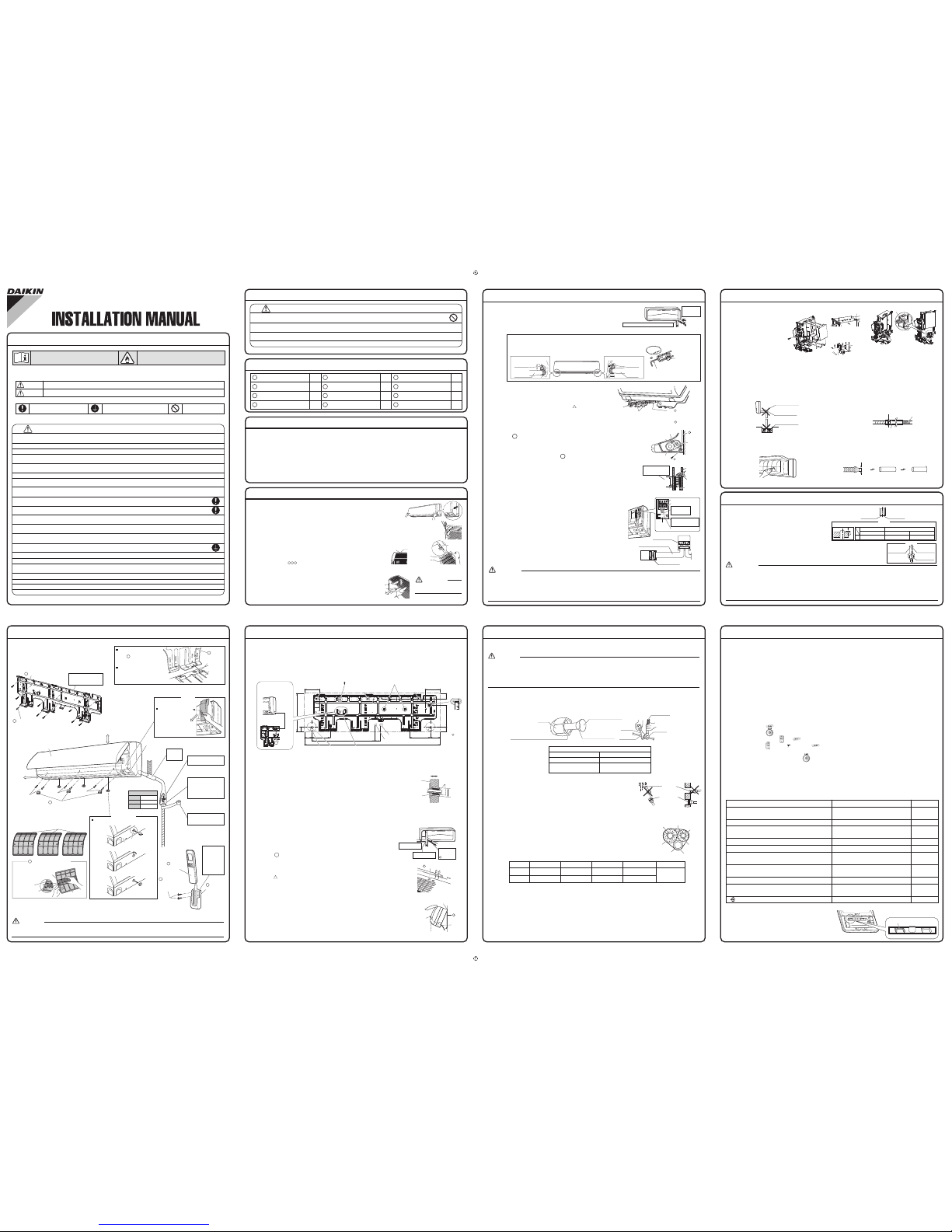
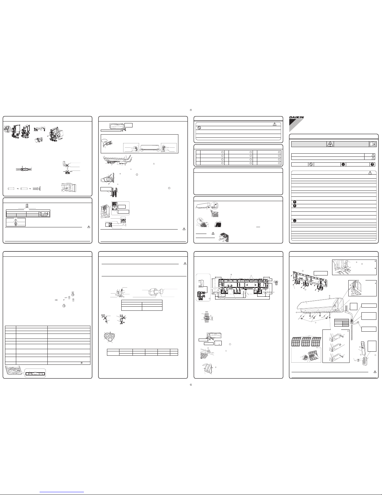
Mounting plate
Dry batteries AAA. LR03
(alkaline)
Operation manual
Mounting plate fixing
screws M4 × 25L
Indoor unit fixing screws
M4 × 12L
Remote controller holder
Fixing screws for remote
controller holder M3 × 20L
Screw cover
J
Insulation tape
Wireless remote controller
Titanium apatite photocatalytic
air-purifying filters
3
Installation manual
Accessories
Installation Tips (1
)
1. Removing and installing the front panel
• Removal method
Hook fingers on the tabs on the left and right of the main body, and open until the
panel stops. Slide the front panel sideways to disengage the front panel shaft.
Then pull the front panel toward you to remove it.
• Installation method
Align the tabs of the front panel with the grooves, and push all the way in. Then close slowly.
Push the centre of the lower panel surface firmly to engage the tabs.
2. Removing and installing the front grille
• Removal method
1) Remove the front panel to remove the air filter.
2) Remove 6 screws from the front grille.
3) In front of the mark on the front grille, there are 4 upper hooks.
Lightly pull the front grille toward you with one hand, and push down on the hooks with the fingers of your other hand.
<When there is insufficient work space because the unit is close to ceiling>
Place both hands under the centre of the front grille, and while pushing up,
pull it toward you.
• Installation method
1)
Install the front grille and firmly engage the upper hooks (4 locations).
2) Install 6 screws of the front grille.
3) Install the air filter and then mount the front panel.
Be sure to wear protection
gloves.
CAUTION
• Before choosing the installation site, obtain user approval.
1. Indoor unit
•
The indoor unit should be positioned in a place where:
1)
the restrictions on the installation requirements specified
in the indoor unit installation drawings are met,
2) both the air inlet and air outlet are unobstructed,
3) the unit is not exposed to direct sunlight,
4) the unit is away from sources of heat or steam,
5) there is no source of machine oil vapour (this may
shorten the indoor unit service life),
6) cool (warm) air is circulated throughout the room,
7)
the unit is away from electronic ignition type
fluorescent lamps (inverter or rapid start type) as
they may affect the remote controller range,
8)
the unit is at least 1m away from any television or radio set
(the unit may cause interference with the picture or sound),
9)
the unit can be installed at the recommended height (2.5m),
10) no laundry equipment is located.
2. Wireless remote controller
•
Turn on all the fluorescent lamps in the room, if any,
and find a location where the remote controller signals
are properly received by the indoor unit (within 7m).
Choosing an Installation Site
mark area
(4 locations)
Upper hook
1) Push up.
2) Pull toward you.
CAUTION
• Do not install the air conditioner at any place where there is a danger of flammable gas leakage.
In the event of a gas leakage, build-up of gas near the air conditioner may cause a fire to break out.
• Tighten the flare nut as specified, such as with a torque wrench.
If the flare nut is too tight, it may crack after prolonged use, causing refrigerant leakage.
• Only qualified personnel can handle, fill, purge and dispose of the refrigerant.
N004
• While following the instructions in this installation manual, install drain piping to ensure proper drainage and insulate
the piping to prevent condensation.
Improper drain piping may result in indoor water leakage and property damage.
This product is not designed for re-packing. In case of re-packing contact to Daikin dealer.
Push the front panel
shaft of the front panel
into the groove.
Push
down.
Upper hook
Indoor Unit Installation Drawings
INTELLIGENT EYE sensor
• Do not hit or forcefully push the intelligent-eye sensor. This can lead to damage and malfunction.
•
Do not place large objects near the sensor. Also keep heating units or humidifiers outside the sensor’s detection area.
CAUTION
30mm or more
from ceiling
INTELLIGENT EYE
sensor
50mm or more
from walls
(on both sides)
Front panel
M4 × 16L
M4 × 16L
M4 × 16L
Screw cover (3 pcs)
M
Wrap the thermal insulation
pipe with the finishing tape
from bottom to top.
Cut thermal insulation
pipe to an appropriate
length and wrap it with
tape, making sure that no
gap is left in the insulation
pipe’s cut line.
Caulk pipe
hole gap
with putty.
A
Mounting plate
Mounting plate fixing
screws M4 × 25L (9 pcs)
B
The mounting plate
should be installed on a
wall which can support the
weight of the indoor unit.
Air filters
The service lid is
removable.
Opening method
1)
Remove the service
lid screws.
2)
Pull out the service
lid diagonally down
in the direction of
the arrow.
3)
Pull down.
Service lid
The flare connection should
be installed outdoors.
C
Titanium apatite photocatalytic
air-purifying filter (3 pcs)
Titanium apatite photocatalytic
air-purifying filter
Filter frame
Air filter
Tab
D Wireless
remote controller
E
Remote
controller holder
Fixing screws for
remote controller
holder M3 × 20L
(2 pcs)
F
Before screwing
the remote
controller holder
to the wall, make
sure that control
signals are
properly received
by indoor unit.
1)
Insert the tool into the groove of the front grille fixture.
How to remove front grille fixture
2) Turn the tool 90° in the direction of the arrow.
3) Take out the front grille fixture.
Bottom of indoor unit
Front grille fixture
Front grille fixture
How to attach the indoor unit.
Hook the tabs of the bottom frame
to the mounting plate.
If the tabs are difficult to hook,
remove the front grille.
How to remove the indoor unit.
Push up the marked area (at the
lower part of the front grille) to
release the tabs. If it is difficult to
release, remove the front grille.
Front grille
A
Mounting
plate
Tab
Bottom frame
Mark (rear side)
A
Unit dimensions
Height
Width
Depth
340mm
1200mm
240mm
1. Installing the mounting plate
• The mounting plate should be installed on a wall which can support the weight of the indoor unit.
1) Temporarily secure the mounting plate to the wall, make sure that the panel is completely level, and
mark the boring points on the wall.
2) Secure the mounting plate to the wall with screws.
Recommended mounting plate retention spots and dimensions
Indoor Unit Installation (1)
2. Drilling a wall hole and installing wall embedded pipe
• For metal frame or metal board walls, be sure to use a wall embedded
pipe and wall hole cover in the feed-through hole to prevent possible heat,
electrical shock, or fire.
• Be sure to caulk the gaps around the pipes with caulking material to
prevent water leakage.
1) Drill a feed-through hole with a 80mm diameter through the wall at a
downward angle toward the outside.
2) Insert a wall embedded pipe into the hole.
3) Insert a wall hole cover into wall pipe.
4)
After completing refrigerant piping, wiring, and drain piping, caulk the pipe hole gap with putty.
3. Installing the indoor unit
3-1. Right-side, right-back, or right-bottom piping
1) Attach the drain hose to the underside of the refrigerant pipes
with an adhesive vinyl tape.
2) Wrap the refrigerant pipes and drain hose together with
insulation tape.
3) Pass the drain hose and refrigerant pipes through the wall hole,
then set the indoor unit on the mounting plate hooks by using the
markings at the top of the indoor unit as a guide.
4) Open the front panel, then open the service lid.
(Refer to Installation Tips.)
5) Pass the inter-unit wire from the outdoor unit through the feedthrough wall hole and then through the back of the indoor unit.
Pull them through the front side.
Bend the ends of cable tie wires upward for easier work in advance.
(If the inter-unit wire ends are to be stripped first, bundle the wire
lead ends with adhesive tape.)
6) Press the bottom frame of the indoor unit with both hands to set it
on the mounting plate hooks. Make sure that the wire leads do
not catch on the edge of the indoor unit.
J
Inside Outside
Caulking(field supply)
Wall embedded pipe
(field supply)
φ80
Right-bottom
piping
Right-back piping
Right-side piping
Bind refrigerant
pipe and drain
hose together with
insulation tape.
J
Remove pipe port cover
here for right-side piping.
Remove pipe port cover
here for right-bottom piping.
Mounting plate
A
45
190
53
134131
45
340
65.3
φ80
161
182.5 89
φ80
1200
47
554
unit: mm
Use a tape
measure
as shown.
Position
the end of
the tape
measure
at .
Gas pipe end
Liquid pipe end
Place the pipe port cover
in this pocket.
Through-the-wall
hole φ80mm
Drain hose
position
Removed pipe
port cover
The removed pipe port
cover can be kept in the
mounting plate pocket.
Recommended mounting plate
retention spots (9 spots in all)
(Bolt size: M10) (Bolt size: M10) (Bolt size: M10)
Place a leveler on these tabs.
A
Mounting
plate
Wire guide
When stripping the
ends of inter-unit
wire in advance,
bundle the wire
lead ends with tape.
Hang indoor unit’s hook here.
Inter-unit
wiring
Mounting
plate
A
Wall hole cover
(field supply)
Indoor Unit Installation (2)
3-2. Left-side, left-back, or left-bottom piping
1) Attach the drain hose to the underside of the refrigerant
pipes with adhesive vinyl tape.
2) Be sure to connect the drain hose to the drain port in
place of the drain plug.
3) Shape the refrigerant pipes along the pipe path
marking on the mounting plate.
4)
Pass the drain hose and refrigerant pipes through
the wall hole, then position the indoor unit on the
mounting plate hooks, using the markings at
the top of the indoor unit as a guide.
5) Pull in the inter-unit wire.
6) Connect the refrigerant pipes.
7) In case of pulling the drain hose through the back of the indoor
unit, wrap the refrigerant pipes and drain hose together with
J insulation tape as shown in the right figure.
8)
While exercising care so that the inter-unit wiring does not catch the
indoor unit, press the bottom edge of the indoor unit with both hands until
it is firmly caught by the mounting plate hooks. Secure the indoor unit to
the mounting plate with the
H
indoor unit fixing screws (M4 × 12L).
3-3. Wall embedded piping
Follow the instructions given under left-side, left-back, or
left-bottom piping.
1) Insert the drain hose to this depth so it won’t be pulled out of
the drain pipe.
4. Wiring
1) Strip wire ends (20mm).
2) Match wire colours with terminal numbers on the indoor and
outdoor unit’s terminal blocks and firmly secure the wires in
the corresponding terminals with the screws.
3) Connect the earth wires to the corresponding terminals.
4) Pull the wires lightly to make sure they are securely
connected, then secure them with the wire retainer.
5) In case of connecting to an adapter system, run the remote
controller cable and attach the S21.
(Refer to “5. When connecting to an HA system”.)
6) Shape the wires so that the service lid fits securely, then close the
service lid.
•
Do not use tapped wires, extension cords, or starburst connections, as they may cause overheating, electrical
shock,or fire.
• Do not use locally purchased electrical parts inside the product. (Do not branch the power for the drain pump,
etc., from the terminal block.) Doing so may cause electric shock or fire.
• Do not connect the power wire to the indoor unit. Doing so may cause electric shock or fire.
WARNING
How to set the drain hose.
• Insert drain hose and tighten fixing screw.
Forgetting to attach this may cause water leakages.
The drain hose is on the back of the unit.
How to set the drain plug.
Front side of unit
Drain hose attachment position
Attachment on the left side
Drain hose
Fixing screw
Attachment on the right side (factory default)
Drain hose
Fixing screw
Remove pipe port cover here for left-bottom piping.
Remove pipe port
cover here for
left-side piping.
Left-bottom piping
Left-side
piping
Left-back
piping
No gap
Insert a hexagon
wrench (4mm)
Wrap insulation tape
around the bent portion of the
refrigerant pipe.
Overlap at least half the width
of the
insulation tape with
each turn.
Drain
hose
Caulk this hole
with putty or
caulking material.
Bind with vinyl
tape.
Mounting plate
Refrigerant
pipes
Drain hose
Bottom frame
M4 × 12L (3 locations)
Inter-unit wire
Mounting
plate
Inner wall
Vinyl chloride
drain pipe
(VP-30)
Drain hose
50mm
or more
Insert drain hose to this
depth so it won’t be
pulled out of drain pipe.
Outer wall
Shape wires so
that the service
lid will fit securely.
Terminal block
Electrical wiring box
Wire retainer
Firmly secure the wire
retainer so that wires
sustain no external stress.
Use the
specified
wire type.
Do not apply
lubricating oil
(refrigerant oil) to
the drain plug when
inserting it.
The application of
lubrication oil to the
drain plug will
deteriorate the plug
to cause drain
leakage from the
plug.
A
A
H
J
J
1
2
3
12 3 LN
Inter-unit wire
4-core 1.5mm² or more
60245 IEC 57
Firmly fix the wires with
the terminal screws.
Outdoor unit
Indoor
unit
Firmly fix the wires with
the terminal screws.
5. When connecting to an HA system
1) Remove the front grille.
(6 screws, 3 front grille
fixtures)
2) Remove the electrical
wiring box. (1 screw)
3)
Remove the metal plate
electrical wiring box cover.
(4 tabs)(See Fig.1)
4) Attach the connection
cord to the S21 connector
and pull the harness out
through the notched part in the figure. (See Fig.2)
5)
Replace the electrical wiring box cover as it was, and pull the harness around, as shown in the figure.(See Fig.3)
Indoor Unit Installation (3)
Refrigerant Piping Work (1)
6. Drain piping
1) Connect the drain hose, as described below.
2) Remove the air filters and pour some water
into the drain pan to check the water flows
smoothly.
3)
When drain hose requires extension, obtain an
extension hose with an inner diameter of 16mm.
Be sure to thermally insulate the indoor
section of the extension hose.
4)
When connecting a rigid polyvinyl chloride pipe
(nominal diameter 13mm) directly to the drain
hose attached to the indoor unit as with embedded
piping work, use any commercially available drain
socket (nominal diameter 13mm) as a joint.
1. Flaring the pipe end
1) Cut the pipe end with a pipe cutter.
2)
Remove burrs with the cut surface facing
downward so that the chips do not enter the
pipe.
3) Put the flare nut on the pipe.
4) Flare the pipe.
5) Check that the flaring is properly made.
• Do not use mineral oil on flared part.
• Prevent mineral oil from getting into the system as this would reduce the lifetime of the units.
•
Never use piping which has been used for previous installations. Only use parts which are delivered with the unit.
• Never install a drier to this R32 unit in order to guarantee it’s lifetime.
• The drying material may dissolve and damage the system.
• Incomplete flaring may cause refrigerant gas leakage.
WARNING
(Cut exactly at
right angles.)
Remove burrs
Set exactly at the position shown below.
A
Flaring
Die
A 0-0.5mm
Clutch-type
Flare tool for R32 or R410A
1.0-1.5mm
Clutch-type (Rigid-type)
1.5-2.0mm
Wing-nut type (Imperial-type)
Conventional flare tool
Check
Flare’s inner
surface must
be flaw-free.
The pipe end must
be evenly flared in
a perfect circle.
Make sure that the
flare nut is fitted.
Fig.1 Fig.2 Fig.3
The drain hose should
be inclined downward.
No trap is permitted.
Do not put the end
of the hose in water.
Indoor unit
drain hose
φ16
Extension drain hose
Heat insulation tube
(field supply)
Drain hose supplied with
the indoor unit
Commercially available drain
socket
(nominal diameter 13mm)
Commercially available rigid
polyvinyl chloride pipe
(nominal diameter 13mm)
φ16
Screw
Pull
Pull
Slide
Tab
Tab
Slide
Metal plate
electrical cover
Main body
HA connector
(S21)
HA connector
(S21)
Lay the HA cord as
shown in the figure.
Refrigerant Piping Work (2)
2. Refrigerant piping
2-1. Caution on piping handling
1) Protect the open end of the pipe against dust and moisture.
2) All pipe bends should be as gentle as possible. Use a pipe
bender for bending.
2-2. Selection of copper and heat insulation materials
• When using commercial copper pipes and fittings, observe the following:
1) Insulation material: Polyethylene foam
Heat transfer rate: 0.041 to 0.052W/mK (0.035 to 0.045kcal/mh°C)
Refrigerant gas pipe’s surface temperature reaches 110°C max.
Choose heat insulation materials that will withstand this temperature.
2)
Be sure to insulate both the gas and liquid piping and observe the
insulation dimensions as below.
3) Use separate thermal insulation pipes for gas and liquid refrigerant pipes.
• Align the centres of both flares and tighten the flare nuts 3 or 4 turns by hand. Then tighten them fully
with the torque wrenches.
• Refrigerant oil for R410A can also be used for application to the inner flare.
• Use the flare nut fixed to the main unit.
(This is to prevent cracking of the flare nut as a result of deterioration over time.)
• To prevent gas leakage, apply refrigeration oil only to the inner surface of the flare.
(Use refrigeration oil for R32.)
•
Use a torque wrench when tightening the flare nuts to prevent damage to the flare nuts and gas leakage.
CAUTION
Wall
If no flare cap is
available, cover
the flare mouth
with tape to keep
dirt or water out.
Be sure to
place a cap.
Rain
Flare nut tightening torque
Gas side Liquid side
61.8-75.4N
m
(630-770kgf cm)
14.2-17.2N m
(144-175kgf cm)
15.9mm 6.4mm
Do not apply refrigeration
oil to the outer surface.
Flare nut
Apply refrigeration oil to the
inner surface of the flare.
Do not apply refrigeration
oil to the flare nut to avoid tightening
with excessive torque.
Apply oil
Torque wrench
Piping union
Flare nut
Spanner
Tighten
Gas pipe
Inter-unit wire
Liquid pipe
Gas pipe
insulation
Liquid pipe
insulation
Finishing tape
Drain hose
Gas side
Piping size
O.D. 15.9mm
O.D. 6.4mm
50mm or more
30mm or more
1.0mm (C1220T-O)
0.8mm (C1220T-O)
I.D. 16-20mm
I.D. 8-10mm
10mm Min.
Minimum bend radius
Piping thickness Thermal insulation size
Thermal insulation
thickness
Liquid side
Trial Operation and Testing
Test items
Incomplete cooling/heating functionNo refrigerant gas leaks.
Draining line is properly installed.
Indoor and outdoor units are installed properly on
solid bases.
Refrigerant gas and liquid pipes and indoor drain
hose extension are thermally insulated.
Fall, vibration, noise
Water leakage
Water leakage
System is properly earthed. Electrical leakage
Indoor unit properly receives remote controller
commands.
No operation
Incomplete cooling/heating function
Incomplete cooling/heating function
The specified wires are used for inter-unit wiring
connections.
No operation or burn damage
Symptom
Check
will appear when the MODE button is pressed.* No heating
Indoor or outdoor unit’s air inlet or air outlet are
unobstructed.
* Check that the jumper (J8) has not been cut. If it has been
cut, contact the service shop.
Stop valves are opened.
1. Trial operation and testing
• Trial operation should be carried out in either COOL or HEAT operation.
1-1 Measure the supply voltage and make sure that it is within the specified range.
1-2 In COOL operation, select the lowest programmable temperature; in HEAT operation,
select the highest programmable temperature.
1-3 Carry out the trial operation in accordance with the operation manual to ensure that all
functions and parts, such as louvres movement, are working properly.
• For protection, the system disables restart operation for 3 minutes after it is turned off.
• When trial operation is conducted in the HEAT operation directly after the circuit breaker is turned on, in
some cases no air will be output for about 10 minutes in order to protect the air conditioner.
1-4 After trial operation is complete, set the temperature to a normal level (26°C to 28°C in COOL
operation, 20°C to 24°C in HEAT operation).
• When operating the air conditioner in COOL operation in winter, or HEAT operation in summer, set it to the trial
operation mode using the following method.
1) Press and select the trial operation (COOL or HEAT).
2) Press to turn on the system.
3) Press both of and at the same time.
4) Press , select “ ”,and press for confirmation.
• Trial operation will stop automatically after about 30 minutes.
To stop the operation, press .
• Some of the functions cannot be used in the trial operation mode.
• The air conditioner draws a small amount of power in its standby mode. If the system is not to be used for some
time after installation, shut off the circuit breaker to eliminate unnecessary power consumption.
• If the circuit breaker trips to shut off the power to the air conditioner, the system will restore the original operation
mode when the circuit breaker is opened again.
Jumper (J8)
2. Test items
01_EN_3P384095-2.indd 1 11/4/2014 1:08:19 PM
HA ﻡﺎﻈﻨﺑ ﻪﻠﻴﺻﻮﺗ ﺪﻨﻋ .5
.ﺔﻴﻣﺎﻣﻷﺍ ﺔﻜﺒﺸﻟﺍ ﻉﺰﻧﺍ (1
ﺔﻜﺒﺸﻠﻟ ﺕﺎﺘﺒﺜﻣ 3 ،ﻲﻏﺍﺮﺑ 6)
(ﺔﻴﻣﺎﻣﻷﺍ
ﻙﻼﺳﻷﺍ ﺪﻳﺪﲤ ﻕﻭﺪﻨﺻ ﻉﺰﻧﺍ
(2
(ﻲﻏﺮﺑ 1) .ﺔﻴﺋﺎﺑﺮﻬﻜﻟﺍ
ﺀﺎﻄﻏ ﻦﻣ ﺔﻴﻧﺪﻌﳌﺍ ﺔﺣﻮﻠﻟﺍ ﻉﺰﻧﺍ
(3
.ﺔﻴﺋﺎﺑﺮﻬﻜﻟﺍ ﻙﻼﺳﻷﺍ ﺪﻳﺪﲤ ﻕﻭﺪﻨﺻ
(
1 ﻞﻜﺸﻟﺍ ﺮﻈﻧﺍ) (ﺔﻨﺴﻟﺃ 4)
ﻞﻴﺻﻮﺘﻟﺍ ﻚﻠﺳ ﺖﻴﺒﺜﺘﺑ ﻢﻗ
(4
ﻦﻣ ﻂﺑﺮﳌﺍ ﺐﺤﺳﺍﻭ S21 ﻞﺻﻮﳌﺎﺑ
.ﻞﻜﺸﻟﺍ ﻲﻓ ﻪﻴﻟﺇ ﺭﺎﺸﳌﺍ ﺀﺰﳉﺍ ﻝﻼﺧ
(
2 ﻞﻜﺸﻟﺍ ﺮﻈﻧﺍ)
،ﻪﻟﻮﺣ ﻦﻣ ﻂﺑﺮﳌﺍ ﺐﺤﺳﺍﻭ ،ﻪﻴﻠﻋ ﻥﺎﻛ ﺎﻤﻛ ﺔﻴﺋﺎﺑﺮﻬﻜﻟﺍ ﻙﻼﺳﻷﺍ ﺪﻳﺪﲤ ﻕﻭﺪﻨﺻ ﺀﺎﻄﻏ ﻉﺎﺟﺭﺈﺑ ﻢﻗ
(5
(3 ﻞﻜﺸﻟﺍ ﺮﻈﻧﺍ) .ﻞﻜﺸﻟﺍ ﻲﻓ ﺢﺿﻮﻣ ﻮﻫ ﺎﻤﻛ
(3) ﺔﻴﻠﺧﺍﺪﻟﺍ ﺓﺪﺣﻮﻟﺍ ﺐﻴﻛﺮﺗ
ﻒﻳﺮﺼﺘﻟﺍ ﺏﻮﺒﻧﺃ ﺪﻳﺪﲤ .6
.ﻩﺎﻧﺩﺃ ﺩﺪﺤﻣ ﻮﻫ ﺎﻤﻛ ،ﻒﻳﺮﺼﺘﻟﺍ ﻡﻮﻃﺮﺧ ﻞﻴﺻﻮﺘﺑ ﻢﻗ (1
ﺀﺎﻋﻭ ﻞﺧﺍﺩ ﻩﺎﻴﳌﺍ ﻦﻣ ﻞﻴﻠﻘﻟﺍ ﺐﻜﺳﺍﻭ ﺀﺍﻮﻬﻟﺍ ﺕﺎﺤﺷﺮﻣ ﻉﺰﻧﺍ (2
.ﺔﺳﻼﺴﺑ ﺀﺎﳌﺍ ﻖﻓﺪﺗ ﻦﻣ ﻖﻘﺤﺘﻠﻟ ﻒﻳﺮﺼﺘﻟﺍ
ﻞﺼﺣﺍ ،ﻲﻓﺎﺿﺇ ﺀﺰﺟ ﺩﻮﺟﻭ ﻒﻳﺮﺼﺘﻟﺍ ﻡﻮﻃﺮﺧ ﺐﻠﻄﺘﻳ ﺎﻣﺪﻨﻋ
(3
.ﱈ 16 ﻎﻠﺒﻳ ﻲﻠﺧﺍﺩ ﺮﻄﻘﺑ ﻡﻮﻃﺮﺨﻠﻟ ﺪﻳﺪﲤ ﺔﻠﺻﻭ ﻰﻠﻋ
ﻡﻮﻃﺮﳋﺍ ﺪﻳﺪﲤ ﺔﻠﺻﻭ ﻦﻣ ﻲﻠﺧﺍﺪﻟﺍ ﺀﺰﳉﺍ ﻝﺰﻋ ﻦﻣ ﺪﻛﺄﺗ
.ﺎﹰﻳﺭﺍﺮﺣ
ﻞﻴﻨﻴﻔﻟﺍ ﺪﻳﺭﻮﻠﻛ ﺓﺩﺎﻣ ﻦﻣ ﻉﻮﻨﺼﳌﺍ ﺏﻮﺒﻧﻷﺍ ﻞﻴﺻﻮﺗ ﺪﻨﻋ
(4
ﻲﻓ ﺮﺷﺎﺒﻣ ﹴﻞﻜﺸﺑ (ﱈ 13 ﻎﻠﺒﻳ ﻲﻤﺳﺍ ﺮﻄﻗ) ﺔﺒﻠﺼﻟﺍ
ﻡﺎﻴﻘﻟﺍ ﺀﺎﻨﺛﺃ ﺔﻴﻠﺧﺍﺪﻟﺍ ﺓﺪﺣﻮﻟﺎﺑ ﺖﺒﺜﳌﺍ ﻒﻳﺮﺼﺘﻟﺍ ﻡﻮﻃﺮﺧ
ﺲﺑﺎﻘﻣ ﻦﻣ ﺎﹰﻳﺃ ﻞﻤﻌﺘﺳﺍ ،ﺔﺠﻣﺪﳌﺍ ﺐﻴﺑﺎﻧﻷﺍ ﺪﻳﺪﲤ ﻝﺎﻤﻋﺄﺑ
.ﺔﻠﺻﻮﻛ (ﱈ
13 ﻎﻠﺒﻳ ﻲﻤﺳﺍ ﺮﻄﻗ) ﺎ
ﹰ
ﻳﺭﺎﲡ ﺓﺮﻓﻮﺘﳌﺍ ﻒﻳﺮﺼﺘﻟﺍ
(1) ﺪﻳﺮﺒﺘﻟﺍ ﻞﺋﺎﺳ ﺐﻴﺑﺎﻧﺃ ﺪﻳﺪﲤ ﻝﺎﻤﻋﺃ
ﺏﻮﺒﻧﻷﺍ ﻑﺮﻃ ﺔﻌﺳﻮﺗ .1
.ﺐﻴﺑﺎﻧﺃ ﻊﻃﺎﻗ ﻝﺎﻤﻌﺘﺳﺎﺑ ﺏﻮﺒﻧﻷﺍ ﻑﺮﻃ ﻊﻄﻗﺍ (1
ﺚﻴﺤﺑ ﻞﻔﺳﻸﻟ ﻪﺠﺘﳌﺍ ﻉﻮﻄﻘﳌﺍ ﺢﻄﺴﻟﺍﻭ ﺕﺍﺀﻮﺘﻨﻟﺍ ﻉﺰﻧﺍ (2
.ﺏﻮﺒﻧﻷﺍ ﻞﺧﺍﺩ ﺕﺎﻗﺎﻗﺮﻟﺍ ﻞﺧﺪﺗ ﻻ
.ﺏﻮﺒﻧﻷﺍ ﻰﻠﻋ ﺔﻌﺳﻮﺘﻟﺍ ﺔﻟﻮﻣﺎﺻ ﻊﺿﻮﺑ ﻢﻗ
(3
.ﺏﻮﺒﻧﻷﺍ ﺔﻌﺳﻮﺘﺑ ﻢﻗ (4
.ﺢﻴﺤﺻ ﹴﻞﻜﺸﺑ ﺔﻌﺳﻮﺘﻟﺍ ﺖﲤ ﺪﻗ ﻪﻧﺃ ﻦﻣ ﻖﻘﲢ (5
.ﺔﻌﺳﻮﺘﻟﺍ ﺀﺰﺟ ﻰﻠﻋ ﻲﻧﺪﻌﻣ ﺖﻳﺯ ﻝﺎﻤﻌﺘﺳﺍ ﻰﻟﺇ ﺪﻤﻌﺗ ﻻ •
.ﺕﺍﺪﺣﻮﻠﻟ ﻲﻠﻴﻐﺸﺘﻟﺍ ﺮﻤﻌﻟﺍ ﻞﻴﻠﻘﺗ ﻲﻓ ﻚﻟﺫ ﺐﺒﺴﺘﻳ ﺪﻘﻓ ﻡﺎﻈﻨﻟﺍ ﻰﻟﺇ ﻲﻧﺪﻌﳌﺍ ﺖﻳﺰﻟﺍ ﻝﻮﺧﺩ ﻯﺩﺎﻔﺗ •
.ﻂﻘﻓ ﺓﺪﺣﻮﻟﺍ ﻊﻣ ﺔﻘﻓﺮﳌﺍ ﻊﻄﻘﻟﺍ ﻝﺎﻤﻌﺘﺳﺎﺑ ﻢﻗ .ﺔﻘﺑﺎﺳ ﺐﻴﻛﺮﺗ ﺕﺎﻴﻠﻤﻋ ﻲﻓ ﺎﻬﻟﺎﻤﻌﺘﺳﺍ ﰎ ﺐﻴﺑﺎﻧﺃ ﻝﺎﻤﻌﺘﺳﺍ ﻰﻟﺇ ﺍﹰﺪﺑﺃ ﺪﻤﻌﺗ ﻻ •
.ﺓﺪﺣﻮﻠﻟ ﻲﻠﻴﻐﺸﺘﻟﺍ ﺮﻤﻌﻟﺍ ﻥﺎﻤﻀﻟ ﻚﻟﺫﻭ R32 ﺯﺎﻐﺑ ﺄﺒﻌﺗ ﻲﺘﻟﺍ ﺓﺪﺣﻮﻟﺍ ﻩﺬﻫ ﻰﻠﻋ ﻒﻔﺠﻣ ﺐﻴﻛﺮﺗ ﻰﻟﺇ ﺍﹰﺪﺑﺇ ﺪﻤﻌﺗ ﻻ •
.ﻪﻔﻠﺗﻭ ﻡﺎﻈﻨﻟﺍ ﻚﻴﻜﻔﺗ ﻰﻠﻋ ﻒﻴﻔﺠﺘﻟﺍ ﺩﺍﻮﻣ ﻞﻤﻌﺗ ﺪﻗ •
.ﺪﻳﺮﺒﺘﻟﺍ ﺯﺎﻏ ﺐﻳﺮﺴﺗ ﻲﻓ ﺐﺒﺴﺘﻳ ﺪﻗ ﺔﻌﺳﻮﺘﻟﺍ ﻡﺎﲤﺇ ﻡﺪﻋ •
ﺮﻳﺬﲢ
ﺎﻳﺍﻭﺰﻟﺍ ﺪﻨﻋ ﻊﻄﻗﺍ)
(.ﺎﹰﻣﺎﲤ ﻰﻨﻤﻴﻟﺍ
ﺕﺍﺀﻮﺘﻨﻟﺍ ﻉﺰﻧﺍ
.ﺎﹰﻣﺎﲤ ﻩﺎﻧﺩﺃ ﺢﺿﻮﳌﺍ ﻊﺿﻮﳌﺍ ﻲﻓ ﺎﻬﻌﺿﻮﺑ ﻢﻗ
A
ﺔﻌﺳﻮﺘﻟﺍ
ﺐﻟﺎﻗ
A
ﱈ 0.5-0
ﺾﺑﺎﻘﻟﺍ ﺯﺍﺮﻃ
R410A ﻭﺃ R32 ﺯﺎﻐﻟ ﺔﺼﺼﺍ ﺔﻌﺳﻮﺘﻟﺍ ﺓﺍﺩﺃ
ﱈ 1.5-1.0
(ﺐﻠﺼﻟﺍ ﺯﺍﺮﻄﻟﺍ) ﺾﺑﺎﻘﻟﺍ ﺯﺍﺮﻃ
ﱈ 2.0-1.5
(ﻱﺭﻮﻃﺍﺮﺒﻣﻻﺍ ﺯﺍﺮﻄﻟﺍ ﻦﻣ) ﺔﺤﻨﺍ ﺔﻟﻮﻣﺎﺼﻟﺍ ﺯﺍﺮﻃ
ﺔﻳﺪﻴﻠﻘﺗ ﺔﻌﺳﻮﺗ ﺓﺍﺩﺃ
ﻖﻘﲢ
ﻑﺮﻃ ﺔﻌﺳﻮﺗ ﻲﻐﺒﻨﻳ
ﻱﺮﺋﺍﺩ ﹴﻞﻜﺸﺑ ﺏﻮﺒﻧﻷﺍ
.ﻞﻣﺎﻛﻭ ﻢﻈﺘﻨﻣ
ﺖﻴﺒﺜﺗ ﰎ ﺪﻗ ﻪﻧﺃ ﻦﻣ ﺪﻛﺄﺗ
.ﺔﻌﺳﻮﺘﻟﺍ ﺔﻟﻮﻣﺎﺻ
ﺢﻄﺴﻟﺍ ﻥﻮﻜﻳ ﻥﺃ ﻲﻐﺒﻨﻳ
ﺔﻌﺳﻮﺘﻟﺍ ﻦﻣ ﻲﻠﺧﺍﺪﻟﺍ
.ﺏﻮﻴﻌﻟﺍ ﻦﻣ ﹴﻝﺎﺧ
1 ﻞﻜﺸﻟﺍ2 ﻞﻜﺸﻟﺍ3 ﻞﻜﺸﻟﺍ
ﻡﻮﻃﺮﺧ ﺔﻟﺎﻣﺇ ﻲﻐﺒﻨﻳ
.ﻞﻔﺳﻷﺍ ﻮﺤﻧ ﻒﻳﺮﺼﺘﻟﺍ
.ﺔﻜﺒﺷ ﻊﻨﺼﺑ ﻡﺎﻴﻘﻟﺍ ﻊﻨﳝ
ﻑﺮﻃ ﻊﺿﻭ ﻰﻟﺇ ﺪﻤﻌﺗ ﻻ
.ﺀﺎﳌﺍ ﻲﻓ ﻡﻮﻃﺮﳋﺍ
ﻒﻳﺮﺼﺗ ﻡﻮﻃﺮﺧ
ﺔﻴﻠﺧﺍﺪﻟﺍ ﺓﺪﺣﻮﻟﺍ
16 ﺮﻄﻗ
ﻒﻳﺮﺼﺘﻟﺍ ﻡﻮﻃﺮﺧ ﺪﻳﺪﲤ ﺔﻠﺻﻭ
ﻱﺭﺍﺮﳊﺍ ﻝﺰﻌﻟﺍ ﺏﻮﺒﻧﺃ
(ﺩﺍﺪﻣﻹﺍ ﻕﺎﻄﻧ)
ﻊﻣ ﻖﻓﺮﻣ ﻒﻳﺮﺼﺘﻟﺍ ﻡﻮﻃﺮﺧ
ﺔﻴﻠﺧﺍﺪﻟﺍ ﺓﺪﺣﻮﻟﺍ
ﺎﹰﻳﺭﺎﲡ ﺮﻓﻮﺘﳌﺍ ﻒﻳﺮﺼﺘﻟﺍ ﺲﺒﻘﻣ
(ﱈ
13 ﻎﻠﺒﻳ ﻲﻤﺳﺍ ﺮﻄﻗ)
ﺪﻳﺭﻮﻠﻛ ﺓﺩﺎﻣ ﻦﻣ ﻉﻮﻨﺼﳌﺍ ﺏﻮﺒﻧﻷﺍ
ﺎﹰﻳﺭﺎﲡ ﺮﻓﻮﺘﳌﺍ ﺔﺒﻠﺼﻟﺍ ﻞﻴﻨﻴﻔﻟﺍ
(ﱈ
13 ﻎﻠﺒﻳ ﻲﻤﺳﺍ ﺮﻄﻗ)
16 ﺮﻄﻗ
(S21) HA ﻞﺻﻮﳌﺍ
HA ﻚﻠﺴﻟﺍ ﺪﻳﺪﻤﺘﺑ ﻢﻗ
.ﻞﻜﺸﻟﺍ ﻲﻓ ﺢﺿﻮﻣ ﻮﻫ ﺎﻤﻛ
HA ﻞﺻﻮﳌﺍ
(S21)
ﺐﺤﺳﺍ
ﺐﺤﺳﺍ
ﻪﻘﻟﺰﺑ ﻢﻗ
ﻥﺎﺴﻠﻟﺍ
ﻥﺎﺴﻠﻟﺍ
ﻪﻘﻟﺰﺑ ﻢﻗ
ﺡﻮﻠﻟﺍ ﺀﺎﻄﻏ
ﻲﻧﺪﻌﳌﺍ
ﻲﺋﺎﺑﺮﻬﻜﻟﺍ
ﻲﺳﺎﺳﻷﺍ ﻞﻜﻴﻬﻟﺍ
ﻲﻏﺮﺒﻟﺍ
(2) ﺪﻳﺮﺒﺘﻟﺍ ﻞﺋﺎﺳ ﺐﻴﺑﺎﻧﺃ ﺪﻳﺪﲤ ﻝﺎﻤﻋﺃ
ﺪﻳﺮﺒﺘﻟﺍ ﻞﺋﺎﺳ ﺐﻴﺑﺎﻧﺃ ﺪﻳﺪﲤ .2
ﺎﻫﺪﺸﺑ ﻢﻗ ﻢﺛ ﻦﻣﻭ .ﻙﺪﻴﺑ ﺕﺍﺮﻣ 4 ﻭﺃ 3 ﺎﻬﻔﻠﺑ ﺔﻌﺳﻮﺘﻟﺍ ﻞﻴﻣﺍﻮﺻ ﺪﺷ ﻰﻠﻋ ﻞﻤﻋﺍﻭ ﺔﻌﺳﻮﳌﺍ ﺀﺍﺰﺟﻷﺍ ﻼﻛ ﻲﻓ ﺔﻳﺰﻛﺮﳌﺍ ﺀﺍﺰﺟﻷﺍ ﺓﺍﺫﺎﺤﲟ ﻢﻗ •
.ﻡﺰﻌﻟﺍ ﺢﻴﺗﺎﻔﲟ ﻞﻣﺎﻛ ﹴﻞﻜﺸﺑ
.ﺔﻌﺳﻮﺘﻟﺍ ﺀﺰﺟ ﻦﻣ ﻲﻠﺧﺍﺪﻟﺍ ﺢﻄﺴﻟﺍ ﻰﻠﻋ ﻪﻘﻴﺒﻄﺘﻟ
R410A ﺪﻳﺮﺒﺘﻟﺍ ﻞﺋﺎﺳ ﺖﻳﺯ ﻝﺎﻤﻌﺘﺳﺍ ﺎ
ﹰ
ﻀﻳﺃ ﻦﻜﳝ •
.ﺔﻴﺴﻴﺋﺮﻟﺍ ﺓﺪﺣﻮﻟﺎﺑ ﺔﺘﺒﺜﳌﺍ ﺔﻌﺳﻮﺘﻟﺍ ﺔﻟﻮﻣﺎﺻ ﻞﻤﻌﺘﺳﺍ •
(.ﺖﻗﻮﻟﺍ ﺭﻭﺮﻣ ﻊﻣ ﺀﺍﺩﻷﺍ ﺭﻮﻫﺪﺘﻟ ﺔﺠﻴﺘﻨﻛ ﺔﻌﺳﻮﺘﻟﺍ ﺔﻟﻮﻣﺎﺻ ﻲﻓ ﻖﻘﺸﺗ ﺙﻭﺪﺣ ﻱﺩﺎﻔﺘﻟ ﺎﹰﻤﻬﻣ ﺍﺬﻫ ﺪﻌﹸﻳ)
.ﺔﻌﺳﻮﺘﻟﺍ ﺀﺰﺟ ﻦﻣ ﻂﻘﻓ ﻲﻠﺧﺍﺪﻟﺍ ﺢﻄﺴﻟﺍ ﻰﻠﻋ ﺪﻳﺮﺒﺘﻟﺍ ﻞﺋﺎﺳ ﺖﻳﺯ ﻊﺿﻮﺑ ﻢﻗ ،ﺯﺎﻐﻟﺍ ﺐﻳﺮﺴﺗ ﻱﺩﺎﻔﺘﻟ
•
(.R32 ﺪﻳﺮﺒﺘﻟﺍ ﻞﺋﺎﺳ ﺖﻳﺯ ﻞﻤﻌﺘﺳﺍ)
.ﺯﺎﻐﻟﺍ ﺏﺮﺴﺗ ﻱﺩﺎﻔﺗﻭ ﺔﻌﺳﻮﺘﻟﺍ ﻞﻴﻣﺍﻮﺻ ﻲﻓ ﻒﻠﺗ ﺙﻭﺪﺣ ﻱﺩﺎﻔﺘﻟ ﺔﻌﺳﻮﺘﻟﺍ ﻞﻴﻣﺍﻮﺻ ﺪﺷ ﺪﻨﻋ ﻡﺰﻌﻟﺍ ﺡﺎﺘﻔﻣ ﻞﻤﻌﺘﺳﺍ
•
ﻪﻴﺒﻨﺗ
ﺐﻴﺑﺎﻧﻷﺍ ﻊﻣ ﻞﻣﺎﻌﺘﻟﺍ ﻝﻮﺣ ﻪﻴﺒﻨﺗ .1-2
.ﺔﺑﻮﻃﺮﻟﺍﻭ ﺭﺎﺒﻐﻟﺍ ﻦﻣ ﺏﻮﺒﻧﻷﺍ ﻦﻣ ﺡﻮﺘﻔﳌﺍ ﻑﺮﻄﻟﺍ ﺔﻳﺎﻤﺤﺑ ﻢﻗ (1
ﻞﻤﻌﺘﺳﺍ .ﻉﺎﻄﺘﺴﳌﺍ ﺭﺪﻗ ﻖﻓﺮﺑ ﺏﻮﺒﻧﻷﺍ ﺕﺍﺀﺎﻨﺜﻧﺍ ﻊﻴﻤﺟ ﻊﻣ ﻞﻣﺎﻌﺘﻟﺍ ﻲﻐﺒﻨﻳ (2
.ﻲﻨﺜﻟﺎﺑ ﻡﺎﻴﻘﻠﻟ ﺏﻮﺒﻧﻷﺍ ﻲﻨﺛ ﺓﺍﺩﺃ
ﺔﻳﺭﺍﺮﺣ ﻝﺰﻋ ﺩﺍﻮﻣﻭ ﺔﻴﺳﺎﺤﻧ ﺩﺍﻮﻣ ﺭﺎﻴﺘﺧﺍ .
2-2
:ﻲﻟﺎﺘﻟﺍ ﻊﺒﺗﺍ ،ﺔﻳﺭﺎﺠﺘﻟﺍ ﺐﻴﻛﺮﺘﻟﺍ ﺕﺍﻭﺩﺃﻭ ﺱﺎﺤﻨﻟﺍ ﺐﻴﺑﺎﻧﺃ ﻝﺎﻤﻌﺘﺳﺍ ﺪﻨﻋ •
ﲔﻠﻴﺛﺇ ﻲﻟﻮﺒﻟﺍ ﺓﻮﻏﺭ :ﺔﻟﺯﺎﻋ ﺩﺍﻮﻣ (1
ﻦﻔﻠﻛ ﻲﻠﻠﻴﻣ/ﻁﺍﻭ 0.052 ﻰﻟﺇ 0.041 ﻦﻣ :ﺓﺭﺍﺮﳊﺍ ﻞﻘﻧ ﻝﺪﻌﻣ
(ﺔﻳﻮﺌﻣ ﺔﺟﺭﺩ/ﺮﺘﻣ/ﺔﻋﺎﺳ/ﻱﺭﻮﻟﺎﻛ ﻮﻠﻴﻛ
0.045 ﻰﻟﺇ 0.035 ﻦﻣ)
.ﻰﺼﻗﺃ ﺪﺤﻛ ﻡ°
110 ﻰﻟﺇ ﺪﻳﺮﺒﺘﻟﺍ ﺯﺎﻏ ﺏﻮﺒﻧﺃ ﺢﻄﺳ ﺓﺭﺍﺮﺣ ﺔﺟﺭﺩ ﻞﺼﺗ
.ﻩﺬﻫ ﺓﺭﺍﺮﳊﺍ ﺔﺟﺭﺩ ﻞﻤﺤﺘﺗ ﺔﻳﺭﺍﺮﺣ ﻝﺰﻋ ﺩﺍﻮﻣ ﺭﺎﻴﺘﺧﺎﺑ ﻢﻗ
ﻝﺰﻌﻟﺍ ﺩﺎﻌﺑﺃ ﺬﻴﻔﻨﺗ ﻲﻓ ﺪﻴﻘﺘﻟﺎﺑ ﻢﻗﻭ ﻞﺋﺎﺴﻟﺍﻭ ﺯﺎﻐﻟﺍ ﺐﻴﺑﺎﻧﺃ ﻦﻣ ﹴﻞﻛ ﻝﺰﻋ ﻰﻠﻋ ﺹﺮﺣﺍ
(2
.ﻩﺎﻧﺩﺃ ﺢﺿﻮﻣ ﻮﻫ ﺎﻤﻛ
ﺔﻌﺳﻮﺘﻟﺍ ﺔﻟﻮﻣﺎﺻ ﺪﺸﻟ ﻡﺰﻌﻟﺍ ﺡﺎﺘﻔﻣ
ﻞﺋﺎﺴﻟﺍ ﺐﻧﺎﺟ ﺯﺎﻐﻟﺍ ﺐﻧﺎﺟ
ﻡ
ﻥ 17.2-14.2
(ﻢﺳ ﻕ ﻢﺠﻛ 175-144)
ﻡ
ﻥ 75.4-61.8
(ﻢﺳ ﻕ ﻢﺠﻛ 770-630)
ﱈ
6.4 ﱈ 15.9
ﺔﻌﺳﻮﺘﻟﺍ ﺔﻟﻮﻣﺎﺻ
ﻡﺰﻌﻟﺍ ﺡﺎﺘﻔﻣ
ﺐﻴﺑﺎﻧﻷﺍ ﺪﻳﺪﲤ ﺓﺪﺣﻭ
ﻂﺑﺭ ﺡﺎﺘﻔﻣ
ﻩﺪﺸﺑ ﻢﻗ
ﺪﻳﺮﺒﺘﻟﺍ ﻞﺋﺎﺳ ﺖﻳﺯ ﻊﺿﻭ ﻰﻟﺇ ﺪﻤﻌﺗ ﻻ
.ﻲﺟﺭﺎﳋﺍ ﺢﻄﺴﻟﺍ ﻰﻠﻋ
ﺔﻌﺳﻮﺘﻟﺍ ﺔﻟﻮﻣﺎﺻ
ﺢﻄﺴﻟﺍ ﻲﻓ ﺪﻳﺮﺒﺘﻟﺍ ﻞﺋﺎﺳ ﺖﻳﺯ ﻊﺿﻮﺑ ﻢﻗ
.ﺔﻌﺳﻮﺘﻟﺍ ﺀﺰﺟ ﻦﻣ ﻂﻘﻓ ﻲﻠﺧﺍﺪﻟﺍ
ﻰﻠﻋ ﺪﻳﺮﺒﺘﻟﺍ ﻞﺋﺎﺳ ﺖﻳﺯ ﻊﺿﻭ ﻰﻟﺇ ﺪﻤﻌﺗ ﻻ
ﻁﺮﻔﻣ ﹴﻞﻜﺸﺑ ﻩﺪﺷ ﻱﺩﺎﻔﺘﻟ ﺔﻌﺳﻮﺘﻟﺍ ﺔﻟﻮﻣﺎﺻ
.ﻡﺰﻌﻟﺍ ﺡﺎﺘﻔﻣ ﻝﺎﻤﻌﺘﺳﺎﺑ
ﺖﻳﺰﻟﺍ ﻊﺿﻭ
ﺭﺍﺪﳉﺍ
ﺀﺎﻄﻏ ﺮﻓﻮﺗ ﻡﺪﻋ ﻝﺎﺣ ﻲﻓ
ﺔﻴﻄﻐﺘﺑ ﻢﻗ ،ﺔﻌﺳﻮﺘﻟﺍ
ﻂﻳﺮﺸﺑ ﺔﻌﺳﻮﺘﻟﺍ ﺔﺤﺘﻓ
ﻭﺃ ﺥﺎﺳﻭﻷﺍ ﻦﻣ ﺎﻬﻈﻔﳊ
.ﻩﺎﻴﳌﺍ
ﻰﻠﻋ ﺹﺮﺣﺍ
.ﺀﺎﻄﻏ ﻊﺿﻭ
ﺮﻄﳌﺍ
ﺯﺎﻐﻟﺍ ﺏﻮﺒﻧﺃ
ﻲﻠﺧﺍﺪﻟﺍ ﺓﺪﺣﻮﻟﺍ ﻚﻠﺳ
ﻞﺋﺎﺴﻟﺍ ﺏﻮﺒﻧﺃ
ﺯﺎﻐﻟﺍ ﺏﻮﺒﻧﺃ ﻝﺰﻋ
ﻞﺋﺎﺴﻟﺍ ﺏﻮﺒﻧﺃ ﻝﺰﻋ
ﻲﺋﺎﻬﻨﻟﺍ ﺰﻴﻬﺠﺘﻟﺍ ﻂﻳﺮﺷ
ﻒﻳﺮﺼﺘﻟﺍ ﻡﻮﻃﺮﺧ
.ﺪﻳﺮﺒﺘﻟﺍ ﻞﺋﺎﺳﻭ ﺪﻳﺮﺒﺘﻟﺍ ﺯﺎﻏ ﺐﻴﺑﺎﻧﻷ ﺔﻠﺼﻔﻨﻣ ﻱﺭﺍﺮﺣ ﻝﺰﻋ ﺐﻴﺑﺎﻧﺃ ﻞﻤﻌﺘﺳﺍ (3
ﺮﺜﻛﺃ ﻭﺃ ﱈ 50
ﺯﺎﻐﻟﺍ ﺐﻧﺎﺟ
ﱈ
15.9 ﺔﻴﺟﺭﺎﳋﺍ ﺩﺎﻌﺑﻷﺍ
ﻞﺋﺎﺴﻟﺍ ﺐﻧﺎﺟ
ﱈ
6.4 ﺔﻴﺟﺭﺎﳋﺍ ﺩﺎﻌﺑﻷﺍﺮﺜﻛﺃ ﻭﺃ ﱈ 30
(C1220T-O)
ﱈ 1.0
(C1220T-O)
ﱈ 0.8
ﱈ 20-16 ﺔﻴﻠﺧﺍﺪﻟﺍ ﺩﺎﻌﺑﻷﺍ
ﻰﻧﺩﺃ ﺪﺤﻛ ﱈ 10
ﱈ 10-8 ﺔﻴﻠﺧﺍﺪﻟﺍ ﺩﺎﻌﺑﻷﺍ
ﺐﻴﺑﺎﻧﻷﺍ ﺕﺍﺪﻳﺪﲤ ﺱﺎﻘﻣﻲﻨﺜﻟﺍ ﺮﻄﻗ ﻒﺼﻨﻟ ﻰﻧﺩﻷﺍ ﺪﳊﺍﺐﻴﺑﺎﻧﻷﺍ ﺕﺍﺪﻳﺪﲤ ﺔﻛﺎﻤﺳﻱﺭﺍﺮﳊﺍ ﻝﺰﻌﻟﺍ ﺐﻴﺑﺎﻧﺃ ﺱﺎﻘﻣﻱﺭﺍﺮﳊﺍ ﻝﺰﻌﻟﺍ ﺐﻴﺑﺎﻧﺃ ﺔﻛﺎﻤﺳ
.ﺔﺌﻓﺪﺘﻟﺍ ﻭﺃ ﺪﻳﺮﺒﺘﻟﺍ ﻊﺿﻮﻟﺍ ﻲﻓ ﻞﻴﻐﺸﺘﻟﺍ ﺪﻨﻋ ﻲﺒﻳﺮﺠﺘﻟﺍ ﻞﻴﻐﺸﺘﻟﺍ ﻢﺘﻳ ﻥﺃ ﻲﻐﺒﻨﻳ •
.ﺩﺪﶈﺍ ﻕﺎﻄﻨﻟﺍ ﻦﻤﺿ ﺎﻬﻧﺃ ﻦﻣ ﺪﻛﺄﺗﻭ ﺔﻴﻄﻟﻮﻔﻟﺎﺑ ﺩﺍﺪﻣﻹﺍ ﺱﺎﻴﻘﺑ ﻢﻗ 1-1
،ﺔﺌﻓﺪﺘﻟﺍ ﻊﺿﻮﻟﺍ ﻲﻓ ﻞﻴﻐﺸﺘﻟﺍ ﺪﻨﻋﻭ ؛ﺔﺠﻣﺮﺒﻠﻟ ﺔﻠﺑﺎﻗ ﺓﺭﺍﺮﺣ ﺔﺟﺭﺩ ﻞﻗﺃ ﺭﺎﻴﺘﺧﺎﺑ ﻢﻗ ،ﺪﻳﺮﺒﺘﻟﺍ ﻊﺿﻮﻟﺍ ﻲﻓ ﻞﻴﻐﺸﺘﻟﺍ ﺪﻨﻋ 2-1
.ﺔﺠﻣﺮﺒﻠﻟ ﺔﻠﺑﺎﻗ ﺓﺭﺍﺮﺣ ﺔﺟﺭﺩ ﻰﻠﻋﺃ ﺭﺎﻴﺘﺧﺎﺑ ﻢﻗ
ﻞﺜﻣ ،ﺢﻴﺤﺻ ﹴﻮﺤﻧ ﻰﻠﻋ ﻊﻄﻘﻟﺍﻭ ﻒﺋﺎﻇﻮﻟﺍ ﻊﻴﻤﺟ ﻞﻤﻋ ﻥﺎﻤﻀﻟ ﻞﻴﻐﺸﺘﻟﺍ ﻞﻴﻟﺪﻟ ﺎﹰﻘﻓﻭ ﻲﺒﻳﺮﺠﺘﻟﺍ ﻞﻴﻐﺸﺘﻟﺎﺑ ﻢﻗ
3-1
.ﺔﻳﻮﻬﺘﻟﺍ ﺕﺎﺤﺘﻓ ﺔﻛﺮﺣ
.ﻞﻴﻐﺸﺘﻟﺍ ﻑﺎﻘﻳﺇ ﺪﻌﺑ ﻖﺋﺎﻗﺩ
3 ﺓﺪﳌ ﻞﻴﻐﺸﺘﻟﺍ ﺓﺩﺎﻋﺇ ﺔﻴﻠﻤﻋ ﻞﻴﻄﻌﺗ ﻰﻠﻋ ﻡﺎﻈﻨﻟﺍ ﻞﻤﻌﻳ ،ﻲﺋﺎﻗﻭ ﺀﺍﺮﺟﺈﻛ •
ﻢﺘﻳ ﻦﻟ ﺕﻻﺎﳊﺍ ﺾﻌﺑ ﻲﻓ ،ﺔﻴﺋﺎﺑﺮﻬﻜﻟﺍ ﺓﺮﺋﺍﺪﻟﺍ ﻊﻃﺎﻗ ﻞﻴﻐﺸﺗ ﺪﻌﺑ ﺓﺮﺷﺎﺒﻣ ﺔﺌﻓﺪﺘﻟﺍ ﻊﺿﻮﻟﺍ ﻲﻓ ﻲﺒﻳﺮﺠﺘﻟﺍ ﻞﻴﻐﺸﺘﻟﺎﺑ ﻡﺎﻴﻘﻟﺍ ﺪﻨﻋ •
.ﺀﺍﻮﻬﻟﺍ ﻒﻴﻜﻣ ﺔﻳﺎﻤﳊ ﻚﻟﺫﻭ ﺎﹰﺒﻳﺮﻘﺗ ﻖﺋﺎﻗﺩ 10 ﺓﺪﳌ ﺀﺍﻮﻬﻟﺍ ﺝﻭﺮﺧ
ﻲﻓ ﻞﻴﻐﺸﺘﻟﺍ ﺪﻨﻋ ﻡ
°28 ﻰﻟﺇ ﻡ°26) ﻱﺩﺎﻋ ﻯﻮﺘﺴﻣ ﺪﻨﻋ ﺓﺭﺍﺮﳊﺍ ﺔﺟﺭﺩ ﻂﺒﻀﺑ ﻢﻗ ،ﻲﺒﻳﺮﺠﺘﻟﺍ ﻞﻴﻐﺸﺘﻟﺍ ﻡﺎﲤﺇ ﺪﻌﺑ 4-1
.(ﺔﺌﻓﺪﺘﻟﺍ ﻊﺿﻮﻟﺍ ﻲﻓ ﻞﻴﻐﺸﺘﻟﺍ ﺪﻨﻋ ﻡ°24 ﻰﻟﺇ ﻡ°20 ﻭ ،ﺪﻳﺮﺒﺘﻟﺍ ﻊﺿﻮﻟﺍ
ﻊﺿﻭ ﻰﻠﻋ ﻪﻄﺒﻀﺑ ﻢﻗ ،ﻒﻴﺼﻟﺍ ﻞﺼﻓ ﻲﻓ ﺔﺌﻓﺪﺘﻟﺍ ﻊﺿﻮﻟﺍ ﻲﻓ ﻪﻠﻴﻐﺸﺗ ﺪﻨﻋ ﻭﺃ ،ﺀﺎﺘﺸﻟﺍ ﻞﺼﻓ ﻲﻓ ﺪﻳﺮﺒﺘﻟﺍ ﻊﺿﻮﻟﺍ ﻲﻓ ﺀﺍﻮﻬﻟﺍ ﻒﻴﻜﻣ ﻞﻴﻐﺸﺗ ﺪﻨﻋ •
.ﺔﻴﻟﺎﺘﻟﺍ ﺔﻘﻳﺮﻄﻟﺍ ﻉﺎﺒﺗﺍ ﻝﻼﺧ ﻦﻣ ﻲﺒﻳﺮﺠﺘﻟﺍ ﻞﻴﻐﺸﺘﻟﺍ
.(ﺔﺌﻓﺪﺘﻟﺍ ﻭﺃ ﺪﻳﺮﺒﺘﻟﺍ) ﻲﺒﻳﺮﺠﺘﻟﺍ ﻞﻴﻐﺸﺘﻟﺍ ﺭﺎﻴﺘﺧﺎﺑ ﻢﻗﻭ ﻂﻐﺿﺍ
(1
.ﻡﺎﻈﻨﻟﺍ ﻞﻴﻐﺸﺘﻟ ﻂﻐﺿﺍ (2
.ﺖﻗﻮﻟﺍ ﺲﻔﻧ ﻲﻓ ﻭ ﻦﻣ ﹰﻼﻛ ﻂﻐﺿﺍ (3
.ﺪﻴﻛﺄﺘﻠﻟ ﻂﻐﺿﺍﻭ “ ” ﺭﺎﻴﺘﺧﺎﺑ ﻢﻗﻭ ﻂﻐﺿﺍ (4
.ﺎﹰﺒﻳﺮﻘﺗ ﺔﻘﻴﻗﺩ 30 ﺪﻌﺑ ﺎﹰﻴﺋﺎﻘﻠﺗ ﻲﺒﻳﺮﺠﺘﻟﺍ ﻞﻴﻐﺸﺘﻟﺍ ﻒﻗﻮﺘﻴﺳ •
. ﻂﻐﺿﺍ ،ﻞﻴﻐﺸﺘﻟﺍ ﻑﺎﻘﻳﻹ
.ﻲﺒﻳﺮﺠﺘﻟﺍ ﻞﻴﻐﺸﺘﻟﺍ ﻊﺿﻭ ﻲﻓ ﻒﺋﺎﻇﻮﻟﺍ ﺾﻌﺑ ﻝﺎﻤﻌﺘﺳﺍ ﺭﺬﻌﺘﻳ
•
،ﺐﻴﻛﺮﺘﻟﺍ ﺪﻌﺑ ﺖﻗﻮﻟﺍ ﻦﻣ ﺓﺮﺘﻔﻟ ﻡﺎﻈﻨﻟﺍ ﻝﺎﻤﻌﺘﺳﺍ ﻡﺪﻋ ﻝﺎﺣ ﻲﻓ .ﺩﺍﺪﻌﺘﺳﻻﺍ ﻊﺿﻭ ﻲﻓ ﻰﺘﺣ ﺀﺎﺑﺮﻬﻜﻟﺍ ﻦﻣ ﹰﻼﻴﺌﺿ ﺍﹰﺭﺍﺪﻘﻣ ﺎﹰﻤﺋﺍﺩ ﺀﺍﻮﻬﻟﺍ ﻒﻴﻜﻣ ﻚﻠﻬﺘﺴﻳ •
.ﻱﺭﻭﺮﻀﻟﺍ ﺮﻴﻏ ﺭﺎﻴﺘﻟﺍ ﻙﻼﻬﺘﺳﺍ ﻦﻣ ﺪﺤﻠﻟ ﺔﻴﺋﺎﺑﺮﻬﻜﻟﺍ ﺓﺮﺋﺍﺪﻟﺍ ﻊﻃﺎﻗ ﻑﺎﻘﻳﺈﺑ ﻢﻗ
ﻊﻃﺎﻗ ﻞﻴﻐﺸﺗ ﺪﻨﻋ ﻲﻠﺻﻷﺍ ﻞﻴﻐﺸﺘﻟﺍ ﻊﺿﻭ ﺓﺩﺎﻌﺘﺳﺍ ﻰﻠﻋ ﻡﺎﻈﻨﻟﺍ ﻞﻤﻌﻴﺳ ،ﺀﺍﻮﻬﻟﺍ ﻒﻴﻜﻣ ﻦﻋ ﺭﺎﻴﺘﻟﺍ ﻑﺎﻘﻳﺇ ﻦﻋ ﺔﻴﺋﺎﺑﺮﻬﻜﻟﺍ ﺓﺮﺋﺍﺪﻟﺍ ﻊﻃﺎﻗ ﻊﻨﺘﻣﺍ ﺍﺫﺇ
•
.ﻯﺮﺧﺃ ﺓﺮﻣ ﺔﻴﺋﺎﺑﺮﻬﻜﻟﺍ ﺓﺮﺋﺍﺪﻟﺍ
ﻞﺼﺗﺍ ،ﻊﻄﻗ ﺩﻮﺟﻭ ﻝﺎﺣ ﻲﻓ .
(J8) ﻲﻄﺨﺘﻟﺍ ﺔﻠﺻﻭ ﻉﺎﻄﻘﻧﺍ ﻡﺪﻋ ﻦﻣ ﻖﻘﲢ *
.ﺔﻣﺪﳋﺍ ﺰﻛﺮﲟ
ﺭﺎﺒﺘﺧﻻﺍ ﺩﻮﻨﺑ .2
ﺔﻠﻤﺘﻜﻣ ﺮﻴﻏ ﺔﺌﻓﺪﺘﻟﺍ/ﺪﻳﺮﺒﺘﻟﺍ ﺔﻔﻴﻇﻭ .ﺪﻳﺮﺒﺘﻟﺍ ﺯﺎﻐﻟ ﺐﻳﺮﺴﺗ ﺪﺟﻮﻳ ﻻ
.ﺢﻴﺤﺻ ﹴﻞﻜﺸﺑ ﻒﻳﺮﺼﺘﻟﺍ ﻂﺧ ﺐﻴﻛﺮﺗ ﰎ
.ﺢﻴﺤﺻ ﹴﻞﻜﺸﺑ ﺔﺒﻠﺻ ﺓﺪﻋﺎﻗ ﻰﻠﻋ ﺔﻴﺟﺭﺎﳋﺍﻭ ﺔﻴﻠﺧﺍﺪﻟﺍ ﺕﺍﺪﺣﻮﻟﺍ ﺐﻴﻛﺮﺗ ﰎ
ﺪﻳﺮﺒﺘﻟﺍ ﺯﺎﻏ ﺐﻴﺑﺎﻧﺃﻭ ﺪﻳﺮﺒﺘﻟﺍ ﻞﺋﺎﺳ ﺐﻴﺑﺎﻧﻷ ﻱﺭﺍﺮﳊﺍ ﻝﺰﻌﻟﺍ ﺀﺍﺮﺟﺇ ﰎ
.ﺔﻴﻠﺧﺍﺪﻟﺍ ﻒﻳﺮﺼﺘﻟﺍ ﻡﻮﻃﺮﺧ ﺪﻳﺪﲤ ﺔﻠﺻﻭﻭ
ﺀﺎﺿﻮﺿ ،ﺯﺍﺰﺘﻫﺍ ،ﻁﻮﻘﺳ
ﺀﺎﳌﺍ ﺏﺮﺴﺗ
ﺀﺎﳌﺍ ﺏﺮﺴﺗ
.ﺢﻴﺤﺻ ﹴﻞﻜﺸﺑ ﻡﺎﻈﻨﻟﺍ ﺾﻳﺭﺄﺗ ﰎ
ﻲﺋﺎﺑﺮﻬﻛ ﺏﺮﺴﺗ
ﺪﻌﺑ ﻦﻋ ﻢﻜﺤﺘﻟﺍ ﺓﺪﺣﻭ ﺮﻣﺍﻭﺃ ﻝﺎﺒﻘﺘﺳﺎﺑ ﺔﻴﻠﺧﺍﺪﻟﺍ ﺪﺣﻮﻟﺍ ﻡﻮﻘﺗ
.ﺢﻴﺤﺻ ﹴﻞﻜﺸﺑ
ﻞﻴﻐﺸﺗ ﺔﻴﻠﻤﻋ ﺪﺟﻮﺗ ﻻ
ﺔﻠﻤﺘﻜﻣ ﺮﻴﻏ ﺔﺌﻓﺪﺘﻟﺍ/ﺪﻳﺮﺒﺘﻟﺍ ﺔﻔﻴﻇﻭ
ﺔﻠﻤﺘﻜﻣ ﺮﻴﻏ ﺔﺌﻓﺪﺘﻟﺍ/ﺪﻳﺮﺒﺘﻟﺍ ﺔﻔﻴﻇﻭ
ﺔﻴﻠﺧﺍﺪﻟﺍ ﻙﻼﺳﻷﺍ ﺕﻼﻴﺻﻮﺘﻟ ﺔﺼﺼﺍ ﻙﻼﺳﻷﺍ ﻝﺎﻤﻌﺘﺳﺍ ﻢﺘﻳ
.ﺓﺪﺣﻮﻠﻟ
ﺐﺒﺴﺑ ﻒﻠﺗ ﺪﺟﻮﻳ ﻭﺃ ﻞﻴﻐﺸﺗ ﺔﻴﻠﻤﻋ ﺪﺟﻮﺗ ﻻ
ﻕﺍﺮﺘﺣﻻﺍ
*.ﻊﺿﻮﻟﺍ ﺭﺯ ﻂﻐﺿ ﺪﻨﻋ ﺮﻬﻈﺘﺳ ﺔﺌﻓﺪﺗ ﺪﺟﻮﺗ ﻻ
ﺭﺎﺒﺘﺧﻻﺍ ﺩﻮﻨﺑ
ﺽﺍﺮﻋﻷﺍ
ﻖﻘﲢ
ﺕﺍﺪﺣﻮﻠﻟ ﺀﺍﻮﻬﻟﺍ ﺝﺮﺨﻣ ﻭﺃ ﺀﺍﻮﻬﻟﺍ ﻞﺧﺪﻣ ﻦﻣ ﹴﻞﻛ ﻲﻓ ﻖﺋﺍﻮﻋ ﺪﺟﻮﺗ ﻻ
.ﺔﻴﺟﺭﺎﳋﺍﻭ ﺔﻴﻠﺧﺍﺪﻟﺍ
.ﺔﺣﻮﺘﻔﻣ ﻑﺎﻘﻳﻹﺍ ﺕﺎﻣﺎﻤﺻ
ﺭﺎﺒﺘﺧﻻﺍﻭ ﻲﺒﻳﺮﺠﺘﻟﺍ ﻞﻴﻐﺸﺘﻟﺍ
ﺭﺎﺒﺘﺧﻻﺍﻭ ﻲﺒﻳﺮﺠﺘﻟﺍ ﻞﻴﻐﺸﺘﻟﺍ .1
(J8) ﻲﻄﺨﺘﻟﺍ ﺔﻠﺻﻭ
(2) ﺔﻴﻠﺧﺍﺪﻟﺍ ﺓﺪﺣﻮﻟﺍ ﺐﻴﻛﺮﺗ
ﺮﺴﻳﻷﺍ ﻲﻠﻔﺴﻟﺍ ﻭﺃ ﺮﺴﻳﻷﺍ ﻲﻔﻠﳋﺍ ﻭﺃ ﺮﺴﻳﻷﺍ ﻲﺒﻧﺎﳉﺍ ﺏﻮﺒﻧﻷﺍ ﺪﻳﺪﲤ .2-3
ﻞﺋﺎﺳ ﺐﻴﺑﺎﻧﺃ ﻦﻣ ﻲﻠﻔﺴﻟﺍ ﺐﻧﺎﳉﺍ ﻲﻓ ﻒﻳﺮﺼﺘﻟﺍ ﻡﻮﻃﺮﺧ ﺖﻴﺒﺜﺘﺑ ﻢﻗ (1
.ﻖﺻﻻ ﻞﻴﻨﻴﻓ ﻂﻳﺮﺸﺑ ﺪﻳﺮﺒﺘﻟﺍ
ﺲﺑﺎﻗ ﻥﺎﻜﻣ ﻲﻓ ﻒﻳﺮﺼﺘﻟﺍ ﺬﻔﻨﲟ ﻒﻳﺮﺼﺘﻟﺍ ﻡﻮﻃﺮﺧ ﻞﻴﺻﻮﺗ ﻦﻣ ﺪﻛﺄﺗ
(2
.ﻒﻳﺮﺼﺘﻟﺍ
ﺓﻮﺠﻓ ﺪﺟﻮﺗ ﻻ
.ﻒﻳﺮﺼﺘﻟﺍ ﺲﺑﺎﻗ ﻊﺿﻭ ﺔﻴﻔﻴﻛ
(ﱈ 4) ﻲﺳﺍﺪﺳ ﺪﺷ ﺡﺎﺘﻔﻣ ﻞﺧﺩﺃ
ﺖﻳﺯ ﺔﻓﺎﺿﺇ ﻰﻟﺇ ﺪﻤﻌﺗ ﻻ
ﻞﺋﺎﺳ ﺖﻳﺯ) ﻢﻴﺤﺸﺗ
ﺲﺑﺎﻗ ﻰﻟﺇ (ﺪﻳﺮﺒﺘﻟﺍ
.ﻪﻟﺎﺧﺩﺇ ﺪﻨﻋ ﻒﻳﺮﺼﺘﻟﺍ
ﻢﻴﺤﺸﺘﻟﺍ ﺖﻳﺯ ﻊﺿﻭ ﻥﺇ
ﻒﻳﺮﺼﺘﻟﺍ ﺲﺑﺎﻗ ﻰﻠﻋ
ﺲﺑﺎﻘﻟﺍ ﻒﻠﺗ ﻰﻠﻋ ﻞﻤﻌﻴﺳ
ﺩﺍﻮﻣ ﺏﺮﺴﺗ ﺐﺒﺴﺑ
.ﺲﺑﺎﻘﻟﺍ ﻦﻣ ﻒﻳﺮﺼﺘﻟﺍ
ﺮﺴﻳﻷﺍ ﺐﻧﺎﳉﺍ ﻰﻠﻋ ﺖﻴﺒﺜﺘﻟﺍ
ﻒﻳﺮﺼﺘﻟﺍ ﻡﻮﻃﺮﺧ
ﺖﻴﺒﺜﺘﻟﺍ ﻲﻏﺮﺑ
.ﻒﻳﺮﺼﺘﻟﺍ ﻡﻮﻃﺮﺧ ﻊﺿﻭ ﺔﻴﻔﻴﻛ
.ﺖﻴﺒﺜﺘﻟﺍ ﻲﻏﺮﺑ ﺪﺸﺑ ﻢﻗﻭ ﻒﻳﺮﺼﺘﻟﺍ ﻡﻮﻃﺮﺧ ﻞﺧﺩﺃ
•
.ﻩﺎﻴﻤﻠﻟ ﺕﺎﺑﺮﺴﺗ ﺙﻭﺪﺣ ﻰﻟﺇ ﻱﺩﺆﻳ ﺪﻗ ﺖﻴﺒﺜﺘﻟﺎﺑ ﻡﺎﻴﻘﻟﺍ ﻥﺎﻴﺴﻧ ﻥﺇ
.ﺓﺪﺣﻮﻟﺍ ﻦﻣ ﻲﻔﻠﳋﺍ ﺀﺰﳉﺍ ﻲﻓ ﺩﻮﺟﻮﻣ ﻒﻳﺮﺼﺘﻟﺍ ﻡﻮﻃﺮﺧ
ﺓﺪﺣﻮﻟﺍ ﻦﻣ ﻲﻣﺎﻣﻷﺍ ﺐﻧﺎﳉﺍ
ﻒﻳﺮﺼﺘﻟﺍ ﻡﻮﻃﺮﺧ ﺖﻴﺒﺜﺗ ﻊﺿﻮﻣ
ﻦﳝﻷﺍ ﺐﻧﺎﳉﺍ ﻰﻠﻋ ﺖﻴﺒﺜﺘﻟﺍ
(ﻊﻨﺼﳌﺍ ﻲﻓ ﻲﺋﺪﺒﳌﺍ ﻂﺒﻀﻟﺍ)
ﻒﻳﺮﺼﺘﻟﺍ ﻡﻮﻃﺮﺧ
ﺖﻴﺒﺜﺘﻟﺍ ﻲﻏﺮﺑ
ﺏﻮﺒﻧﻷﺍ ﺭﺎﺴﻣ ﻝﻮﻃ ﻰﻠﻋ ﺪﻳﺮﺒﺘﻟﺍ ﻞﺋﺎﺳ ﺐﻴﺑﺎﻧﺃ ﻊﺿﻮﺑ ﻢﻗ (3
.ﻖﻴﻠﻌﺘﻟﺍ ﺔﺣﻮﻟ ﻰﻠﻋ ﺢﺿﻮﳌﺍ
ﻝﻼﺧ ﻦﻣ ﺪﻳﺮﺒﺘﻟﺍ ﻞﺋﺎﺳ ﺐﻴﺑﺎﻧﺃﻭ ﻒﻳﺮﺼﺘﻟﺍ ﻡﻮﻃﺮﺧ ﺮﻳﺮﻤﺘﺑ ﻢﻗ
(4
ﺕﺎﻓﺎﻄﺧ ﻰﻠﻋ ﺔﻴﻠﺧﺍﺪﻟﺍ ﺓﺪﺣﻮﻟﺍ ﻊﺿﻮﺑ ﻢﻗ ﻢﺛ ،ﺭﺍﺪﳉﺍ ﺐﻘﺛ
ﺀﺰﳉﺍ ﻰﻠﻋ ﺓﺩﻮﺟﻮﳌﺍ ﺕﺎﻣﻼﻌﻟﺍ ﻝﺎﻤﻌﺘﺳﺎﺑ ﻖﻴﻠﻌﺘﻟﺍ ﺔﺣﻮﻟ
.ﻱﺩﺎﺷﺭﺇ ﻞﻴﻟﺩ ﺎﻫﺭﺎﺒﺘﻋﺎﺑ ﺔﻴﻠﺧﺍﺪﻟﺍ ﺓﺪﺣﻮﻟﺍ ﻦﻣ ﻱﻮﻠﻌﻟﺍ
.ﺓﺪﺣﻮﻠﻟ ﻲﻠﺧﺍﺪﻟﺍ ﻚﻠﺴﻟﺍ ﺐﺤﺳﺍ
(5
.ﺪﻳﺮﺒﺘﻟﺍ ﻞﺋﺎﺳ ﺐﻴﺑﺎﻧﺃ ﻞﻴﺻﻮﺘﺑ ﻢﻗ (6
ﻢﻗ ،ﺔﻴﻠﺧﺍﺪﻟﺍ ﺓﺪﺣﻮﻠﻟ ﺔﻴﻔﻠﳋﺍ ﺔﻬﳉﺍ ﻝﻼﺧ ﻦﻣ ﻒﻳﺮﺼﺘﻟﺍ ﻡﻮﻃﺮﺧ ﺐﺤﺳ ﰎ ﻝﺎﺣ ﻲﻓ (7
ﺢﺿﻮﻣ ﻮﻫ ﺎﻤﻛ J ﻝﺯﺎﻋ ﻂﻳﺮﺸﺑ ﺎﹰﻌﻣ ﻒﻳﺮﺼﺘﻟﺍ ﻡﻮﻃﺮﺧﻭ ﺪﻳﺮﺒﺘﻟﺍ ﻞﺋﺎﺳ ﺐﻴﺑﺎﻧﺃ ﻒﻠﺑ
.ﺭﺎﺴﻴﻟﺍ ﻰﻠﻋ ﻞﻜﺸﻟﺍ ﻲﻓ
ﻙﻼﺳﻷﺍ ﺕﺍﺪﻳﺪﲤ ﺔﺴﻣﻼﻣ ﻡﺪﻌﻟ ﺭﺬﳊﺍ ﻲﺧﻮﺗ ﺐﺠﻳ ﺔﻧﺎﻴﺼﻟﺎﺑ ﻡﺎﻴﻘﻟﺍ ﻢﺘﻳ ﺎﻤﻨﻴﺑ
(8
ﺎﺘﻠﻜﺑ ﺔﻴﻠﺧﺍﺪﻟﺍ ﺓﺪﺣﻮﻟﺍ ﻦﻣ ﺔﻴﻠﻔﺴﻟﺍ ﺔﻓﺎﳊﺍ ﻰﻠﻋ ﻂﻐﺿﺍ ،ﺔﻴﻠﺧﺍﺪﻟﺍ ﺓﺪﺣﻮﻠﻟ ﺔﻴﻠﺧﺍﺪﻟﺍ
ﺖﻴﺒﺜﺗ ﻡﺎﻜﺣﺈﺑ ﻢﻗ .ﻖﻴﻠﻌﺘﻟﺍ ﺔﺣﻮﻟ ﺕﺎﻓﺎﻄﺧ ﺔﻄﺳﺍﻮﺑ ﻡﺎﻜﺣﺈﺑ ﻖﻠﻌﻳ ﻰﺘﺣ ﻚﻳﺪﻳ
ﺓﺪﺣﻮﻟﺎﺑ ﺔﺻﺎﳋﺍ ﺖﻴﺒﺜﺘﻟﺍ ﻲﻏﺍﺮﺑ ﻝﺎﻤﻌﺘﺳﺎﺑ ﻖﻴﻠﻌﺘﻟﺍ ﺔﺣﻮﻟ ﻰﻠﻋ ﺔﻴﻠﺧﺍﺪﻟﺍ ﺓﺪﺣﻮﻟﺍ
.(
12L × M4 ﺱﺎﻘﻣ) H ﺔﻴﻠﺧﺍﺪﻟﺍ
ﺭﺍﺪﳉﺍ ﻲﻓ ﺞﻣﺪﳌﺍ ﺏﻮﺒﻧﻷﺍ ﺪﻳﺪﲤ .
3-3
ﻭﺃ ﺮﺴﻳﻷﺍ ﻲﻔﻠﳋﺍ ﻭﺃ ﺮﺴﻳﻷﺍ ﻲﺒﻧﺎﳉﺍ ﺏﻮﺒﻧﻷﺍ ﺪﻳﺪﻤﺘﺑ ﺔﺻﺎﳋﺍﻭ ﺓﺎﻄﻌﳌﺍ ﺕﺎﻤﻴﻠﻌﺘﻟﺍ ﻊﺒﺗﺍ
.ﺮﺴﻳﻷﺍ ﻲﻠﻔﺴﻟﺍ
.ﺝﺭﺎﺨﻠﻟ ﻒﻳﺮﺼﺘﻟﺍ ﺏﻮﺒﻧﺃ ﺐﺤﺳ ﻢﺘﻳ ﻻ ﺚﻴﺤﺑ ﻖﻤﻌﻟﺍ ﺍﺬﻬﻟ ﻒﻳﺮﺼﺘﻟﺍ ﻡﻮﻃﺮﺧ ﻞﺧﺩﺃ
(1
ﻙﻼﺳﻷﺍ ﺪﻳﺪﲤ .4
.(ﱈ 20) ﻚﻠﺴﻟﺍ ﻑﺍﺮﻃﺃ ﺔﻳﺮﻌﺘﺑ ﻢﻗ (1
ﻞﺘﻜﻟﺍ ﻰﻠﻋ ﺓﺩﻮﺟﻮﳌﺍ ﻞﻴﺻﻮﺘﻟﺍ ﻑﺍﺮﻃﺃ ﻡﺎﻗﺭﺃ ﻊﻣ ﻚﻠﺴﻟﺍ ﻥﺍﻮﻟﺃ ﺔﻘﺑﺎﻄﲟ ﻢﻗ (2
ﻑﺍﺮﻃﺃ ﻲﻓ ﻙﻼﺳﻷﺍ ﺖﻴﺒﺜﺗ ﻡﺎﻜﺣﺇﻭ ﺔﻴﺟﺭﺎﳋﺍﻭ ﺔﻴﻠﺧﺍﺪﻟﺍ ﺕﺍﺪﺣﻮﻠﻟ ﺔﻴﻓﺮﻄﻟﺍ
.ﻲﻏﺍﺮﺒﻠﻟ ﺔﻘﺑﺎﻄﳌﺍ ﻞﻴﺻﻮﺘﻟﺍ
.ﺎﻬﻟ ﺔﻘﺑﺎﻄﳌﺍ ﻞﻴﺻﻮﺘﻟﺍ ﻑﺍﺮﻃﺄﺑ ﺾﻳﺭﺄﺗ ﻙﻼﺳﺃ ﻞﻴﺻﻮﺘﺑ ﻢﻗ
(3
ﻲﻓ ﺎﻬﺘﻴﺒﺜﺘﺑ ﻢﻗ ﻢﺛ ﻦﻣﻭ ،ﻡﺎﻜﺣﺈﺑ ﺎﻬﻠﻴﺻﻮﺗ ﻦﻣ ﺪﻛﺄﺘﻠﻟ ﺔﻔﺨﺑ ﻙﻼﺳﻷﺍ ﺐﺤﺳﺍ (4
.ﻙﻼﺳﻷﺍ ﺔﻈﻓﺎﺣ
ﺖﻴﺒﺜﺗﻭ ﺪﻌﺑ ﻦﻋ ﻢﻜﺤﺘﻟﺍ ﺓﺪﺣﻭ ﻞﺒﻛ ﻊﺿﻮﺑ ﻢﻗ ،ﻝﻮﺤﻣ ﻡﺎﻈﻨﺑ ﻪﻠﻴﺻﻮﺗ ﰎ ﻝﺎﺣ ﻲﻓ
(5
.S21 ﻞﺻﻮﳌﺍ
(.«
HA ﻡﺎﻈﻨﺑ ﻪﻠﻴﺻﻮﺗ ﺪﻨﻋ .5» ﻊﺟﺍﺭ)
ﻢﻗ ﻢﺛ ﻦﻣﻭ ،ﻡﺎﻜﺣﺈﺑ ﺔﻧﺎﻴﺼﻟﺍ ﺀﺎﻄﻏ ﺐﻴﻛﺮﺗ ﻢﺘﻳ ﺚﻴﺤﺑ ﻙﻼﺳﻷﺍ ﻊﺿﻮﺑ ﻢﻗ
(6
.ﺔﻧﺎﻴﺼﻟﺍ ﺀﺎﻄﻏ ﻕﻼﻏﺈﺑ
ﺔﻣﺪﺻ ﺙﻭﺪﺣ ﻭﺃ ﺪﺋﺍﺯ ﲔﺨﺴﺗ ﺙﻭﺪﺣ ﻲﻓ ﻚﻟﺫ ﺐﺒﺴﺘﻳ ﺪﻘﻓ ،ﻞﻜﺸﻟﺍ ﺔﻴﻤﳒ ﺕﻼﺻﻮﻣ ﻭﺃ ﺪﻳﺪﲤ ﻚﻠﺳ ﻭﺃ ﺔﻋﺮﻔﺘﻣ ﻙﻼﺳﺃ ﻝﺎﻤﻌﺘﺳﺍ ﻰﻟﺇ ﺪﻤﻌﺗ ﻻ •
.ﻖﻳﺮﺣ ﺏﻮﺸﻧ ﻭﺃ ﺔﻴﺋﺎﺑﺮﻬﻛ
ﺔﻠﺘﻜﻟﺍ ﻦﻣ ،ﺦﻟﺇ ،ﻒﻳﺮﺼﺘﻟﺍ ﺔﺨﻀﲟ ﺹﺎﳋﺍ ﺭﺎﻴﺘﻟﺍ ﻚﻠﺳ ﻢﻴﺴﻘﺗ ﻰﻟﺇ ﺪﻤﻌﺗ ﻻ) .ﺞﺘﻨﳌﺍ ﻞﺧﺍﺩ ﹰﺎﻴﻠﺤﻣ ﺎﻫﺅﺍﺮﺷ ﰎ ﺔﻴﺋﺎﺑﺮﻬﻛ ﻊﻄﻗ ﻝﺎﻤﻌﺘﺳﺍ ﻰﻟﺇ ﺪﻤﻌﺗ ﻻ
•
.ﻖﻳﺮﺣ ﺏﻮﺸﻧ ﻭﺃ ﺔﻴﺋﺎﺑﺮﻬﻛ ﺔﻣﺪﺻ ﺙﻭﺪﺣ ﻰﻟﺇ ﻚﻟﺬﺑ ﻡﺎﻴﻘﻟﺍ ﻱﺩﺆﻳ ﺪﻗ (.ﺔﻴﻓﺮﻄﻟﺍ
.ﻖﻳﺮﺣ ﺏﻮﺸﻧ ﻭﺃ ﺔﻴﺋﺎﺑﺮﻬﻛ ﺔﻣﺪﺻ ﺙﻭﺪﺣ ﻰﻟﺇ ﻚﻟﺬﺑ ﻡﺎﻴﻘﻟﺍ ﻱﺩﺆﻳ ﺪﻗ .ﺔﻴﻠﺧﺍﺪﻟﺍ ﺓﺪﺣﻮﻟﺎﺑ ﺭﺎﻴﺘﻟﺍ ﻚﻠﺳ ﻞﻴﺻﻮﺗ ﻰﻟﺇ ﺪﻤﻌﺗ ﻻ
•
ﺮﻳﺬﲢ
1
2
3
12 3 LN
.ﺎﻨﻫ ﺮﺴﻳﻷﺍ ﻲﻠﻔﺴﻟﺍ ﺏﻮﺒﻧﻷﺍ ﺪﻳﺪﻤﺘﻟ ﺏﻮﺒﻧﻷﺍ ﺬﻔﻨﻣ ﺀﺎﻄﻏ ﻉﺰﻧﺍ
ﺬﻔﻨﻣ ﺀﺎﻄﻏ ﻉﺰﻧﺍ
ﺏﻮﺒﻧﻷﺍ ﺪﻳﺪﻤﺘﻟ ﺏﻮﺒﻧﻷﺍ
.ﺎﻨﻫ ﺮﺴﻳﻷﺍ ﻲﺒﻧﺎﳉﺍ
ﺮﺴﻳﻷﺍ ﻲﻠﻔﺴﻟﺍ ﺏﻮﺒﻧﻷﺍ ﺪﻳﺪﲤ
ﺏﻮﺒﻧﻷﺍ ﺪﻳﺪﲤ
ﺮﺴﻳﻷﺍ ﻲﺒﻧﺎﳉﺍ
ﺏﻮﺒﻧﻷﺍ ﺪﻳﺪﲤ
ﺮﺴﻳﻷﺍ ﻲﻔﻠﳋﺍ
ﻒﻳﺮﺼﺘﻟﺍ ﻡﻮﻃﺮﺧ
ﺐﻘﺜﻟﺍ ﺍﺬﻫ ﺪﺴﺑ ﻢﻗ
ﻭﺃ ﻥﻮﺠﻌﻣ ﻝﺎﻤﻌﺘﺳﺎﺑ
.ﻕﻮﻘﺸﻟﺍ ﺪﺴﻟ ﺓﺩﺎﻣ
ﻂﻳﺮﺸﺑ ﻪﻄﺑﺮﺑ ﻢﻗ
.ﻞﻴﻨﻴﻔﻟﺍ
ﻖﻴﻠﻌﺘﻟﺍ ﺔﺣﻮﻟ
A
J
ﻝﻮﺣ ﻝﺯﺎﻌﻟﺍ ﻂﻳﺮﺸﻟﺍ ﻒﻠﺑ ﻢﻗ
ﻞﺋﺎﺳ ﺏﻮﺒﻧﺃ ﻦﻣ ﺔﻴﻨﺤﻨﳌﺍ ﺀﺍﺰﺟﻷﺍ
.ﺪﻳﺮﺒﺘﻟﺍ
ﻂﻳﺮﺸﻟﺍ ﺽﺮﻋ ﻒﺼﻧ ﺔﻠﺧﺍﺪﲟ ﻢﻗ
ﻞﻜﺑ ﻡﺎﻴﻘﻟﺍ ﺀﺎﻨﺛﺃ ﻞﻗﻷﺍ ﻰﻠﻋ ﻝﺯﺎﻌﻟﺍ
.ﺔﻔﻟ
J
ﻞﺋﺎﺳ ﺐﻴﺑﺎﻧﺃ
ﺪﻳﺮﺒﺘﻟﺍ
ﻒﻳﺮﺼﺘﻟﺍ ﻡﻮﻃﺮﺧ
ﻲﻠﻔﺴﻟﺍ ﺭﺎﻃﻹﺍ
ﻲﻠﺧﺍﺪﻟﺍ ﺓﺪﺣﻮﻟﺍ ﻚﻠﺳ
ﻖﻴﻠﻌﺘﻟﺍ ﺔﺣﻮﻟ
A
(ﻊﻗﺍﻮﻣ 3) 12L × M4 ﺱﺎﻘﻣ
H
ﻲﻠﺧﺍﺪﻟﺍ ﺭﺍﺪﳉﺍ
ﻒﻳﺮﺼﺘﻟﺍ ﺏﻮﺒﻧﺃ
ﺓﺩﺎﻣ ﻦﻣ ﻉﻮﻨﺼﳌﺍ
ﻞﻴﻨﻴﻔﻟﺍ ﺪﻳﺭﻮﻠﻛ
(VP-30)
ﻒﻳﺮﺼﺘﻟﺍ ﻡﻮﻃﺮﺧ
ﱈ
50
ﺮﺜﻛﺃ ﻭﺃ
ﺍﺬﻬﻟ ﻒﻳﺮﺼﺘﻟﺍ ﻡﻮﻃﺮﺧ ﻞﺧﺩﺃ
ﺐﺤﺳ ﻢﺘﻳ ﻻ ﺚﻴﺤﺑ ﻖﻤﻌﻟﺍ
.ﺝﺭﺎﺨﻠﻟ ﻒﻳﺮﺼﺘﻟﺍ ﺏﻮﺒﻧﺃ
ﻲﺟﺭﺎﳋﺍ ﺭﺍﺪﳉﺍ
ﻙﻼﺳﻷﺍ ﻊﺿﻮﺑ ﻢﻗ
ﺐﻴﻛﺮﺗ ﻢﺘﻳ ﺚﻴﺤﺑ
.ﻡﺎﻜﺣﺈﺑ ﺔﻧﺎﻴﺼﻟﺍ ﺀﺎﻄﻏ
ﺔﻴﻓﺮﻄﻟﺍ ﺔﻠﺘﻜﻟﺍ
ﺔﻴﺋﺎﺑﺮﻬﻜﻟﺍ ﻙﻼﺳﻷﺍ ﺪﻳﺪﲤ ﻕﻭﺪﻨﺻ
ﻙﻼﺳﻷﺍ ﺔﻈﻓﺎﺣ
ﻡﺎﻜﺣﺈﺑ ﻙﻼﺳﻷﺍ ﺔﻈﻓﺎﺣ ﺖﻴﺒﺜﺘﺑ ﻢﻗ
ﻥﺎﻤﻀﻟ ﻙﻼﺳﻷﺍ ﻰﻠﻋ ﻆﻓﺎﲢ ﺚﻴﺤﺑ
.ﻲﻓﺎﺿﺇ ﻂﻐﻀﻟ ﺎﻬﺿﺮﻌﺗ ﻡﺪﻋ
ﻞﻤﻌﺘﺳﺍ
ﻚﻠﺴﻟﺍ ﻉﻮﻧ
.ﻚﻟﺬﻟ ﺺﺼﺍ
ﻲﻠﺧﺍﺪﻟﺍ ﺓﺪﺣﻮﻟﺍ ﻚﻠﺳ
ﺮﺜﻛﺃ ﻭﺃ
2
ﱈ 1.5 4-ﺐﻠﻟﺍ
IEC 57 60245
ﻡﺎﻜﺣﺈﺑ ﻙﻼﺳﻷﺍ ﺖﻴﺒﺜﺘﺑ ﻢﻗ
.ﻞﻴﺻﻮﺘﻟﺍ ﻑﺍﺮﻃﺃ ﻲﻏﺍﺮﺑ ﻝﺎﻤﻌﺘﺳﺎﺑ
ﺔﻴﺟﺭﺎﳋﺍ ﺓﺪﺣﻮﻟﺍ
ﺓﺪﺣﻮﻟﺍ
ﺔﻴﻠﺧﺍﺪﻟﺍ
ﻡﺎﻜﺣﺈﺑ ﻙﻼﺳﻷﺍ ﺖﻴﺒﺜﺘﺑ ﻢﻗ
.ﻞﻴﺻﻮﺘﻟﺍ ﻑﺍﺮﻃﺃ ﻲﻏﺍﺮﺑ ﻝﺎﻤﻌﺘﺳﺎﺑ
ﻊﻴﻤﺟ ﻉﺎﺒﺗﺍ ﻰﻠﻋ ﺹﺮﺣﺍ .ﺔﻣﻼﺴﻟﺎﺑ ﻖﻠﻌﺘﺗ ﺔﻣﺎﻫ ﺕﺎﻣﻮﻠﻌﻣ ﻰﻠﻋ ﺎﻤﻫﻼﻛ ﻱﻮﺘﺤﻳ .ﻪﻴﺒﻨﺗ ﻭ ﺮﻳﺬﲢ ﺎﻤﻫﻭ ﲔﻋﻮﻧ ﻰﻟﺇ ﺎﻨﻫ ﺓﺩﺭﺍﻮﻟﺍ ﺔﻴﻃﺎﻴﺘﺣﻻﺍ ﺕﺎﻬﻴﺒﻨﺘﻟﺍ ﻒﻴﻨﺼﺗ ﰎ •
.ﻕﺎﻔﺧﺇ ﻥﻭﺩ ﺔﻴﻃﺎﻴﺘﺣﻻﺍ ﺕﺎﻬﻴﺒﻨﺘﻟﺍ
ﻪﻴﺒﻨﺗﻭ ﺮﻳﺬﲢ ﻰﻨﻌﻣ ﻝﻮﺣ ﺕﺎﻇﻮﺤﻠﻣ
•
ﺮﻳﺬﲢ
:ﺔﻴﻟﺎﺘﻟﺍ ﻲﻧﺎﻌﳌﺍ ﻞﻴﻟﺪﻟﺍ ﺍﺬﻫ ﻲﻓ ﺔﻨﻴﺒﳌﺍ ﺔﻣﻼﺴﻟﺍ ﺕﺎﻣﻼﻋ ﻞﻤﲢ •
ﻝﻼﺧ ﻦﻣ ﻪﺑ ﺀﺎﻨﺘﻋﻻﺍﻭ ﺀﺍﻮﻬﻟﺍ ﻒﻴﻜﻣ ﻞﻴﻐﺸﺗ ﺔﻴﻔﻴﻛ ﻡﺪﺨﺘﺴﻤﻠﻟ ﺡﺮﺷﺍﻭ ﺏﻮﻴﻋ ﺩﻮﺟﻭ ﻡﺪﻋ ﻦﻣ ﺪﻛﺄﺘﻠﻟ ﻲﺒﻳﺮﲡ ﻞﻴﻐﺸﺗ ﺀﺍﺮﺟﺈﺑ ﻢﻗ ،ﺐﻴﻛﺮﺘﻟﺍ ﻦﻣ ﺀﺎﻬﺘﻧﻹﺍ ﺪﻌﺑ •
.ﻞﻴﻐﺸﺘﻟﺍ ﻞﻴﻟﺩ
.ﺐﻴﻛﺮﺘﻟﺍ ﺔﻴﻠﻤﻌﺑ ﻡﺎﻴﻘﻟﺍ ﻞﻫﺆﳌﺍ ﻲﻨﻔﻟﺍ ﻭﺃ ﻚﻳﺪﻟ ﻞﻴﻛﻮﻟﺍ ﻦﻣ ﺐﻠﻃﺍ
•
.ﻖﻳﺮﺣ ﺏﻮﺸﻧ ﻭﺃ ﺔﻴﺋﺎﺑﺮﻬﻛ ﺕﺎﻣﺪﺻ ﺙﻭﺪﺣ ﻭﺃ ﻩﺎﻴﳌﺍ ﺏﺮﺴﺗ ﻰﻟﺇ ﻱﺩﺆﻳ ﺪﻗ ﺊﻃﺎﳋﺍ ﺐﻴﻛﺮﺘﻟﺍ .ﻚﺴﻔﻨﺑ ﺀﺍﻮﻬﻟﺍ ﻒﻴﻜﻣ ﺐﻴﻛﺮﺗ ﺔﻟﻭﺎﺤﻣ ﻰﻟﺇ ﺪﻤﻌﺗ ﻻ
.ﻖﻳﺮﺣ ﺏﻮﺸﻧ ﻭﺃ ﺔﻴﺋﺎﺑﺮﻬﻛ ﺕﺎﻣﺪﺻ ﺙﻭﺪﺣ ﻭﺃ ﻩﺎﻴﳌﺍ ﺏﺮﺴﺗ ﻰﻟﺇ ﻱﺩﺆﻳ ﺪﻗ ﺊﻃﺎﳋﺍ ﺐﻴﻛﺮﺘﻟﺍ
.ﺍﺬﻫ ﺐﻴﻛﺮﺘﻟﺍ ﻞﻴﻟﺩ ﻲﻓ ﺓﺭﻮﻛﺬﳌﺍ ﺕﺎﻤﻴﻠﻌﺘﻠﻟ ﺎﹰﻘﻓﻭ ﺀﺍﻮﻬﻟﺍ ﻒﻴﻜﻣ ﺐﻴﻛﺮﺘﺑ ﻢﻗ •
(1) ﺔﻣﻼﺴﻟﺍ ﻝﻮﺣ ﺔﻴﻃﺎﻴﺘﺣﺍ ﺕﺎﻬﻴﺒﻨﺗ
ﺮﻳﺬﲢ
ﻪﻴﺒﻨﺗ
.ﺓﺎﻓﻭ ﺙﻭﺪﺣ ﻰﺘﺣ ﻭﺃ ﺔﻴﺼﺨﺷ ﺡﻭﺮﺠﺑ ﺔﺑﺎﺻﻹﺍ ﻲﻓ ﺐﺒﺴﺘﻳ ﺪﻗ ﺢﻴﺤﺻ ﹴﻞﻜﺸﺑ ﺕﺎﻤﻴﻠﻌﺘﻟﺍ ﻩﺬﻫ ﻉﺎﺒﺗﺍ ﻲﻓ ﻕﺎﻔﺧﻹﺍ ﻥﺇ
.ﺔﻄﻴﶈﺍ ﻑﻭﺮﻈﻠﻟ ﺎﹰﻌﺒﺗ ﺍﹰﺮﻴﻄﺧ ﻥﻮﻜﻳ ﺪﻗ ﻱﺬﻟﺍﻭ ،ﺔﻴﺼﺨﺷ ﺡﻭﺮﺠﺑ ﺔﺑﺎﺻﻹﺍ ﻭﺃ ﺕﺎﻜﻠﺘﻤﻤﻠﻟ ﻒﻠﺗ ﺙﻭﺪﺣ ﻲﻓ ﺐﺒﺴﺘﻳ ﺪﻗ ﺢﻴﺤﺻ ﹴﻞﻜﺸﺑ ﺕﺎﻤﻴﻠﻌﺘﻟﺍ ﻩﺬﻫ ﻉﺎﺒﺗﺍ ﻲﻓ ﻕﺎﻔﺧﻹﺍ ﻥﺇ
.ﺕﺎﻤﻴﻠﻌﺘﻟﺍ ﻉﺎﺒﺗﺍ ﻰﻠﻋ ﺹﺮﺣﺍ.ﻲﻀﻳﺭﺄﺗ ﻞﻴﺻﻮﺗ ﺲﻴﺳﺄﺗ ﻰﻠﻋ ﺹﺮﺣﺍ
.ﺍﹰﺪﺑﺃ ﻝﻭﺎﲢ ﻻ
ﻦﻜﻳﺍﺩ ﻦﻣ ﺀﺍﻮﻬﻟﺍ ﻒﻴﻜﻣ
3P384095-2 M14B149
.ﻖﻳﺮﺣ ﺏﻮﺸﻧ ﻭﺃ ﺔﻴﺋﺎﺑﺮﻬﻛ ﺔﻣﺪﺻ ﺙﻭﺪﺣ ﻭﺃ ﻩﺎﻴﳌﺍ ﺏﺮﺴﺗ ﻭﺃ ،ﺓﺪﺣﻮﻟﺍ ﻁﻮﻘﺳ ﻪﻨﻋ ﺞﺘﻨﻳ ﺪﻗ ﺓﺩﺪﶈﺍ ﺀﺍﺰﺟﻷﺍ ﻝﺎﻤﻌﺘﺳﺍ ﻲﻓ ﻕﺎﻔﺧﻹﺍ .ﺐﻴﻛﺮﺘﻟﺍ ﺔﻴﻠﻤﻋ ﻞﺟﺃ ﻦﻣ ﻂﻘﻓ ﺓﺩﺪﶈﺍ ﺀﺍﺰﺟﻷﺍﻭ ﺕﺎﻴﻟﺎﻤﻜﻟﺍ ﻝﺎﻤﻌﺘﺳﺍ ﻰﻠﻋ ﺹﺮﺣﺍ
•
.ﺍﺬﻫ ﺐﻴﻛﺮﺘﻟﺍ ﻞﻴﻟﺩ ﻲﻓ ﺓﺭﻮﻛﺬﳌﺍ ﺕﺎﻤﻴﻠﻌﺘﻟﺍﻭ ﺔﻠﺼﻟﺍ ﺕﺍﺫ ﺔﻴﻨﻃﻮﻟﺍﻭ ﺔﻴﻠﶈﺍ ﺔﻤﻈﻧﻸﻟ ﺎﹰﻘﻓﻭ ﺔﻴﺋﺎﺑﺮﻬﻜﻟﺍ ﻝﺎﻤﻋﻷﺎﺑ ﻡﺎﻴﻘﻟﺍ ﻲﻐﺒﻨﻳ •
.ﻖﻳﺮﺣ ﺏﻮﺸﻧ ﻭﺃ ﺔﻴﺋﺎﺑﺮﻬﻛ ﺕﺎﻣﺪﺻ ﺙﻭﺪﺣ ﺎﻤﻬﻨﻋ ﺞﺘﻨﻳ ﺪﻗ ﺢﻴﺤﺻ ﺮﻴﻏ ﹴﻞﻜﺸﺑ ﺐﻴﻛﺮﺘﻟﺍ ﻝﺎﻤﻋﺄﺑ ﻡﺎﻴﻘﻟﺍﻭ ﺭﺎﻴﺘﻠﻟ ﻲﻓﺎﻜﻟﺍ ﺮﻴﻏ ﺩﺍﺪﻣﻹﺍ .ﻂﻘﻓ ﻚﻟﺬﻟ ﺔﺼﺼﺍ ﺭﺎﻴﺘﻟﺎﺑ ﺩﺍﺪﻣﻹﺍ ﺓﺮﺋﺍﺩ ﻝﺎﻤﻌﺘﺳﺍ ﻰﻠﻋ ﺹﺮﺣﺍ
.ﻖﻳﺮﺣ ﺏﻮﺸﻧ ﻭﺃ ﺔﻴﺋﺎﺑﺮﻬﻛ ﺔﻣﺪﺻ ﺙﻭﺪﺣ ﻭﺃ ﺪﺋﺍﺰﻟﺍ ﲔﺨﺴﺘﻟﺍ ﻲﻓ ﻚﻟﺫ ﺐﺒﺴﺘﻳ ﺪﻘﻓ ،ﺪﻳﺪﲤ ﻚﻠﺳ ﻭﺃ ﺔﻋﺮﻔﺘﻣ ﻙﻼﺳﺃ ﻝﺎﻤﻌﺘﺳﺍ ﻰﻟﺇ ﺪﻤﻌﺗ ﻻ .ﺐﺳﺎﻨﻣ ﻝﻮﻄﺑ ﻞﺒﻛ ﻝﺎﻤﻌﺘﺳﺎﺑ ﻢﻗ •
.ﻢﻜﺤﺘﻟﺍ ﻕﻭﺪﻨﺻ ﺀﺎﻄﻏ ﺪﺷ ﻡﺎﻜﺣﺇ ﻦﻜﳝ ﺚﻴﺤﺑ ﻙﻼﺳﻷﺍ ﻊﺿﻮﺑ ﻢﻗ ،ﺔﻴﺟﺭﺎﳋﺍﻭ ﺔﻴﻠﺧﺍﺪﻟﺍ ﺕﺍﺪﺣﻮﻟﺍ ﲔﺑ ﻙﻼﺳﻷﺍ ﻞﻴﺻﻮﺗﻭ ﺭﺎﻴﺘﻟﺍ ﺩﺍﺪﻣﺇ ﻙﻼﺳﺃ ﺪﻳﺪﲤ ﺪﻨﻋ •
.ﻞﻴﺻﻮﺘﻟﺍ ﻑﺍﺮﻃﺃ ﺪﺋﺍﺰﻟﺍ ﲔﺨﺴﺘﻟﺍ ﻭﺃ ﻖﻳﺮﺣ ﺏﻮﺸﻧ ﻭﺃ ﺔﻴﺋﺎﺑﺮﻬﻛ ﺔﻣﺪﺻ ﺙﻭﺪﺣ ﻪﻨﻋ ﺞﺘﻨﻳ ﺪﻗ ﺢﻴﺤﺻ ﺮﻴﻏ ﻞﻜﺸﺑ ﻢﻜﺤﺘﻟﺍ ﻕﻭﺪﻨﺻ ﺀﺎﻄﻏ ﻊﺿﻭ
.ﻙﻼﺳﻷﺍ ﻭﺃ ﺔﻴﻓﺮﻄﻟﺍ ﺕﻼﺻﻮﳌﺍ ﻰﻠﻋ ﻁﺮﻔﻣ ﺪﺷ ﺩﻮﺟﻭ ﻡﺪﻋ ﻦﻣﻭ ،ﻚﻟﺬﻟ ﺔﺼﺼﺍ ﻙﻼﺳﻷﺍ ﻝﺎﻤﻌﺘﺳﺍ ﻦﻣﻭ ﻙﻼﺳﻷﺍ ﻊﻴﻤﺟ ﺔﻣﻼﺳ ﻦﻣ ﺪﻛﺄﺗ •
.ﻖﻳﺮﺣ ﺏﻮﺸﻧ ﻭﺃ ﺓﺭﺍﺮﳊﺍ ﻲﻓ ﻲﻌﻴﺒﻃ ﺮﻴﻏ ﺪﻳﺍﺰﺗ ﺎﻬﻨﻋ ﺞﺘﻨﻳ ﺪﻗ ﻙﻼﺳﻷﺍ ﺖﻴﺒﺜﺗ ﻭﺃ ﺔﺌﻃﺎﳋﺍ ﺕﻼﻴﺻﻮﺘﻟﺍ
.ﺓﺪﺣﻮﻟﺍ ﻥﺯﻭ ﻞﹼﻤﺤﺘﻟ ﻲﻓﺎﻛ ﻞﻜﺸﺑ ﺔﻳﻮﻗ ﺓﺪﻋﺎﻗ ﻰﻠﻋ ﺀﺍﻮﻬﻟﺍ ﻒﻴﻜﻣ ﺐﻴﻛﺮﺘﺑ ﻢﻗ •
.ﺔﺑﺎﺻﺇ ﺙﻭﺪﺤﺑ ﺐﺒﺴﺘﻟﺍﻭ ﺕﺍﺪﻌﳌﺍ ﻁﻮﻘﺳ ﺎﻬﻨﻋ ﺞﺘﻨﻳ ﺪﻗ ﹴﻑﺎﻛ ﹴﻞﻜﺸﺑ ﺔﻳﻮﻗ ﺮﻴﻏ ﺓﺪﻋﺎﻗ ﺐﻴﻛﺮﺘﺑ ﻡﺎﻴﻘﻟﺍ ﺪﻨﻋ
.ﺪﻳﺮﺒﺘﻟﺍ ﻞﺋﺎﺳ ﺓﺮﺋﺍﺩ ﻰﻟﺇ ﻝﻮﺧﺪﻟﺎﺑ ﺀﺍﻮﻬﻟﺍ ﻞﺜﻣ R32 ﺯﺎﻏ ﺐﻧﺎﺟ ﻰﻟﺇ ﻯﺮﺧﺃ ﺩﺍﻮﻣ ﺔﻳﺃ ﻉﺪﺗ ﻻ ،ﺐﻴﻛﺮﺘﻟﺍ ﻊﻗﻮﻣ ﺮﻴﻴﻐﺗ ﺓﺩﺎﻋﺇ ﻭﺃ ﺀﺍﻮﻬﻟﺍ ﻒﻴﻜﻣ ﺐﻴﻛﺮﺗ ﺪﻨﻋ •
.ﺡﻭﺮﺠﺑ ﺔﺑﺎﺻﻹﺍ ﻰﻟﺇ ﻰﺘﺣﻭ ﺕﺍﺪﻌﳌﺍ ﻒﻠﺗ ﻰﻟﺇ ﻩﺭﻭﺪﺑ ﻱﺩﺆﻳ ﺪﻗ ﻱﺬﻟﺍﻭ ،ﻲﻌﻴﺒﻃ ﺮﻴﻏ ﹴﻞﻜﺸﺑ ﻂﻐﻀﻟﺍ ﻊﻓﺭ ﻲﻓ ﺐﺒﺴﺗ ﺪﻗ ﺪﻳﺮﺒﺘﻟﺍ ﻞﺋﺎﺳ ﺓﺮﺋﺍﺩ ﻲﻓ ﻯﺮﺧﺃ ﺔﺒﻳﺮﻏ ﺩﺍﻮﻣ ﻭﺃ ﺀﺍﻮﻫ ﺩﻮﺟﻭ ﻥﺇ
.ﺭﻮﻔﻟﺍ ﻰﻠﻋ ﺔﻘﻄﻨﳌﺍ ﺔﻳﻮﻬﺘﺑ ﻢﻗ ،ﺐﻴﻛﺮﺘﻟﺍ ﺀﺎﻨﺛﺃ ﺪﻳﺮﺒﺘﻟﺍ ﺯﺎﻏ ﺏﺮﺴﺗ ﺍﺫﺇ •
.ﺭﺎﻧ ﺭﺪﺼﻣ ﻱﻷ ﺪﻳﺮﺒﺘﻟﺍ ﺯﺎﻏ ﺔﺴﻣﻼﻣ ﻝﺎﺣ ﻲﻓ ﺔﻣﺎﺳ ﺕﺍﺯﺎﻏ ﺝﺎﺘﻧﺍ ﻢﺘﻳ ﺪﻗ
.ﺀﺍﻮﻬﻟﺍ ﻒﻴﻜﻣ ﺾﻳﺭﺄﺗ ﻰﻠﻋ ﺹﺮﺣﺍ •
.ﺔﻴﺋﺎﺑﺮﻬﻛ ﺕﺎﻣﺪﺻ ﺙﻭﺪﺣ ﻰﻟﺇ ﻱﺩﺆﻳ ﺪﻗ ﻞﻣﺎﻜﻟﺍ ﺮﻴﻏ ﺾﻳﺭﺄﺘﻟﺍ .ﻒﺗﺎﻬﻟﺎﺑ ﺹﺎﳋﺍ ﻲﺿﺭﻷﺍ ﻚﻠﺴﻟﺎﺑ ﻭﺃ ﻕﺮﺒﻟﺍ ﺕﻼﺻﻮﲟ ﻭﺃ ﺕﺎﻣﺪﳋﺍ ﺏﻮﺒﻧﺄﺑ ﺓﺪﺣﻮﻟﺍ ﺾﻳﺭﺄﺗ ﻰﻟﺇ ﺪﻤﻌﺗ ﻻ
.ﻖﻳﺮﺣ ﺏﻮﺸﻧ ﻭﺃ ﺔﻴﺋﺎﺑﺮﻬﻛ ﺕﺎﻣﺪﺻ ﺙﻭﺪﺣ ﻰﻟﺇ ﻱﺩﺆﻳ ﺪﻗ ﻲﺿﺭﻷﺍ ﺏﺮﺴﺘﻟﺍ ﺓﺮﺋﺍﺩ ﻊﻃﺎﻗ ﺐﻴﻛﺮﺗ ﻲﻓ ﻕﺎﻔﺧﻹﺍ
.ﻲﺿﺭﻷﺍ ﺏﺮﺴﺘﻟﺍ ﺓﺮﺋﺍﺩ ﻊﻃﺎﻗ ﺐﻴﻛﺮﺗ ﻰﻠﻋ ﺹﺮﺣﺍ •
.ﻊﻧﺎﺼﻟﺍ ﻞﺒﻗ ﻦﻣ ﺎﻬﺑ ﻰﺻﻮﳌﺍ ﻚﻠﺗ ﺮﻴﻏ ﻒﻴﻈﻨﺘﻠﻟ ﻭﺃ ﺪﻴﻠﳉﺍ ﺔﻟﺍﺯﺇ ﺔﻴﻠﻤﻋ ﻊﻳﺮﺴﺘﻟ ﻯﺮﺧﺃ ﻞﺋﺎﺳﻭ ﻉﺎﺒﺗﺍ ﻰﻟﺇ ﺪﻤﻌﺗ ﻻ •
ﻞﻤﻌﻳ ﺯﺎﻬﺟ ﻞﻴﻐﺸﺗ ﻭﺃ ﺔﻓﻮﺸﻜﳌﺍ ﺐﻬﻠﻟﺍ ﺔﻨﺴﻟﺃ :ﻝﺎﺜﳌﺍ ﻞﻴﺒﺳ ﻰﻠﻋ) ﺮﻤﺘﺴﻣ ﹴﻞﻜﺸﺑ ﻝﺎﻌﺷﻹﺍ ﺭﺩﺎﺼﻣ ﻞﻴﻐﺸﺘﺑ ﻡﺎﻴﻘﻟﺍ ﻥﻭﺩ ﺔﻓﺮﻏ ﻲﻓ ﺯﺎﻬﳉﺍ ﻦﻳﺰﺨﺗ ﻲﻐﺒﻨﻳ •
.(ﺔﻴﺋﺎﺑﺮﻬﻛ ﺔﻳﺎﻓﺩ ﻞﻴﻐﺸﺗ ﻭﺃ ﺯﺎﻐﻟﺎﺑ
ﺪﻨﻋ ﺎﹰﺣﻮﺘﻔﻣ ﻑﺎﻘﻳﻹﺍ ﻡﺎﻤﺻ ﻥﺎﻛﻭ ﺪﻳﺮﺒﺘﻟﺍ ﻞﺋﺎﺳ ﺐﻴﺑﺎﻧﺃ ﺖﻴﺒﺜﺗ ﻢﺘﻳ ﻢﻟ ﺍﺫﺇ .ﺭﻮﺴﻳﺮﺒﻤﻜﻟﺍ ﻞﻴﻐﺸﺗ ﻞﺒﻗ ﻡﺎﻜﺣﺈﺑ ﺪﻳﺮﺒﺘﻟﺍ ﻞﺋﺎﺳ ﺏﻮﺒﻧﺃ ﺖﻴﺒﺜﺘﺑ ﻢﻗ ،ﺐﻴﻛﺮﺘﻟﺎﺑ ﻡﺎﻴﻘﻟﺍ ﺀﺎﻨﺛﺃ •
.ﺡﻭﺮﺠﺑ ﺔﺑﺎﺻﻹﺍ ﻰﻟﺇ ﻰﺘﺣﻭ ﺕﺍﺪﻌﳌﺍ ﻒﻠﺗ ﻪﻨﻋ ﻢﺠﻨﻳ ﺪﻗ ﻱﺬﻟﺍﻭ ،ﺪﻳﺮﺒﺘﻟﺍ ﻞﺋﺎﺳ ﺓﺮﺋﺍﺩ ﻲﻓ ﻲﻌﻴﺒﻃ ﺮﻴﻏ ﻂﻐﺿ ﺙﻭﺪﺣ ﻲﻓ ﺎﹰﺒﺒﺴﺘﻣ ،ﻞﺧﺍﺪﻟﺍ ﻰﻟﺇ ﺀﺍﻮﻬﻟﺍ ﻂﻔﺷ ﻢﺘﻴﺳ ،ﺭﻮﺴﻳﺮﺒﻤﻜﻟﺍ ﻞﻴﻐﺸﺗ
،ﻞﻔﺳﻸﻟ ﺦﻀﻟﺍ ﺀﺎﻨﺛﺃ ﺎﹰﺣﻮﺘﻔﻣ ﻑﺎﻘﻳﻹﺍ ﻡﺎﻤﺻ ﻥﺎﻛﻭ ﻞﻴﻐﺸﺘﻟﺎﺑ ﺭﻮﺴﻳﺮﺒﻤﻜﻟﺍ ﺮﻤﺘﺳﺍ ﺍﺫﺇ
.ﺪﻳﺮﺒﺘﻟﺍ ﻞﺋﺎﺳ ﺐﻴﺑﺎﻧﺃ ﻉﺰﻧ ﻞﺒﻗ ﺭﻮﺴﻳﺮﺒﻤﻜﻟﺍ ﻞﻴﻐﺸﺗ ﻑﺎﻘﻳﺈﺑ ﻢﻗ ،ﻞﻔﺳﻸﻟ ﺦﻀﻟﺍ ﺀﺎﻨﺛﺃ •
.ﺡﻭﺮﺠﺑ ﺔﺑﺎﺻﻹﺍ ﻰﻟﺇ ﻰﺘﺣﻭ ﺕﺍﺪﻌﳌﺍ ﻒﻠﺗ ﻪﻨﻋ ﻢﺠﻨﻳ ﺪﻗ ﻱﺬﻟﺍﻭ ،ﺪﻳﺮﺒﺘﻟﺍ ﻞﺋﺎﺳ ﺓﺮﺋﺍﺩ ﻲﻓ ﻲﻌﻴﺒﻃ ﺮﻴﻏ ﻂﻐﺿ ﺙﻭﺪﺣ ﻲﻓ ﺎﹰﺒﺒﺴﺘﻣ ،ﺪﻳﺮﺒﺘﻟﺍ ﻞﺋﺎﺳ ﺐﻴﺑﺎﻧﺃ ﻉﺰﻧ ﺪﻨﻋ ﻞﺧﺍﺪﻟﺍ ﻰﻟﺇ ﺀﺍﻮﻬﻟﺍ ﻂﻔﺷ ﻢﺘﻴﺳ
ﺍﺬﻫ ﻲﻓ ﺓﺩﻮﺟﻮﳌﺍ ﺔﻴﻃﺎﻴﺘﺣﻻﺍ ﺕﺎﻬﻴﺒﻨﺘﻟﺍ ﺃﺮﻗﺍ
.ﺓﺪﺣﻮﻟﺍ ﻞﻴﻐﺸﺗ ﻞﺒﻗ ﺔﻳﺎﻨﻌﺑ ﻞﻴﻟﺪﻟﺍ
.R32 ﺯﺎﻐﺑ ﺯﺎﻬﳉﺍ ﺍﺬﻫ ﺔﺌﺒﻌﺗ ﺖﲤ
.ﺐﻴﻛﺮﺘﻟﺍ ﻦﻣ ﺀﺎﻬﺘﻧﻹﺍ ﺪﻌﺑ ﺪﻳﺮﺒﺘﻟﺍ ﺯﺎﻐﻟ ﺏﺮﺴﺗ ﻱﺃ ﺩﻮﺟﻭ ﻡﺪﻋ ﻦﻣ ﻖﻘﲢ •
.ﻥﺮﻓ ﻭﺃ ﺪﻗﻮﻣ ﻭﺃ ﺔﻳﺎﻓﺪﻟﺍ ﺔﺣﻭﺮﻣ ﻞﺜﻣ ،ﺭﺎﻧ ﺭﺪﺼﻣ ﻱﻷ ﻪﺘﺴﻣﻼﻣ ﺖﲤﻭ ﺔﻓﺮﻐﻟﺍ ﻰﻟﺇ ﺪﻳﺮﺒﺘﻟﺍ ﺯﺎﻏ ﺏﺮﺴﺗ ﺍﺫﺇ ﺔﻣﺎﺳ ﺕﺍﺯﺎﻏ ﺝﺎﺘﻧﺍ ﻢﺘﻳ ﺪﻗ
.ﻪﻗﺍﺮﺣﺇ ﻭﺃ ﻪﺒﻘﺛ ﻰﻟﺇ ﺪﻤﻌﺗ ﻻ •
.ﺔﺤﺋﺍﺭ ﺎﻬﻨﻣ ﺭﺪﺼﺗ ﻻ ﺪﻗ ﺪﻳﺮﺒﺘﻟﺍ ﻞﺋﺍﻮﺴﻓ ﺍﹰﺭﺬﺣ ﻦﻛ •
.ﺔﻴﻨﻃﻮﻟﺍ ﺯﺎﻐﻟﺍ ﺔﻤﻈﻧﺃ ﻊﻣ ﻖﻓﺍﻮﺘﻳ ﻥﺃ ﻲﻐﺒﻨﻳ •
.2ﺮﺘﻣ 3.9 ﻦﻣ ﺮﺜﻛﺃ ﺎﻬﺘﺣﺎﺴﻣ ﻎﻠﺒﺗ ﺔﻴﺿﺭﺃ ﺕﺍﺫ ﺔﻓﺮﻏ ﻲﻓ ﻪﻨﻳﺰﺨﺗﻭ ﻪﻠﻴﻐﺸﺗﻭ ﺯﺎﻬﳉﺍ ﺐﻴﻛﺮﺗ ﻢﺘﻳ ﻥﺃ ﻲﻐﺒﻨﻳ •
ﺐﻴﻛﺮﺘﻟﺍ ﻞﻴﻟﺩ
ﺔﻴﻛﺬﻟﺍ ﲔﻌﻟﺍ ﺮﻌﺸﺘﺴﻣ
.ﻞﻄﻋ ﻭﺃ ﻒﻠﺗ ﺙﻭﺪﺣ ﻰﻟﺇ ﺍﺬﻫ ﻱﺩﺆﻳ ﻥﺃ ﻦﻜﳝ .ﺓﻮﻘﺑ ﻪﻌﻓﺩ ﻭﺃ ﺔﻴﻛﺬﻟﺍ ﲔﻌﻟﺍ ﺮﻌﺸﺘﺴﲟ ﻡﺎﻄﺗﺭﻻﺍ ﻰﻟﺇ ﺪﻤﻌﺗ ﻻ •
.ﺮﻌﺸﺘﺴﳌﺍ ﺪﺻﺭ ﺔﻘﻄﻨﻣ ﺝﺭﺎﺧ ﺀﺍﻮﻬﻟﺍ ﺐﻴﻃﺮﺗ ﺓﺰﻬﺟﺃ ﻭﺃ ﺔﺌﻓﺪﺘﻟﺍ ﺕﺍﺪﺣﻮﺑ ﻆﻔﺘﺣﺍ ،ﻚﻟﺫ ﻰﻟﺇ ﺔﻓﺎﺿﻹﺎﺑ .ﺮﻌﺸﺘﺴﳌﺍ ﻦﻣ ﺏﺮﻘﻟﺎﺑ ﺮﻴﺒﻛ ﻢﺠﺣ ﺕﺍﺫ ﺀﺎﻴﺷﺃ ﻊﻀﺗ ﻻ
•
ﻪﻴﺒﻨﺗ
ﺔﻴﻠﺧﺍﺪﻟﺍ ﺓﺪﺣﻮﻟﺍ ﺐﻴﻛﺮﺗ ﺕﺎﻄﻄﺨﻣ
ﺓﺪﺣﻮﻟﺍ ﺩﺎﻌﺑﺃ
ﻉﺎﻔﺗﺭﻻﺍﱈ 340
ﺽﺮﻌﻟﺍﱈ 1200
ﻖﻤﻌﻟﺍﱈ 240
ﺮﺜﻛﺃ ﻭﺃ ﱈ 30
ﻒﻘﺴﻟﺍ ﻦﻣ
ﺔﻴﻣﺎﻣﻷﺍ ﺔﺣﻮﻠﻟﺍ
ﺱﺎﻘﻣ
16L × M4
16L × M4 ﺱﺎﻘﻣ
ﺭﺍﺪﳉﺍ ﻦﻣ ﺮﺜﻛﺃ ﻭﺃ ﱈ 50
(ﲔﺒﻧﺎﳉﺍ ﻼﻛ ﻦﻣ)
ﺱﺎﻘﻣ
16L × M4
(ﻊﻄﻗ 3) ﻲﻏﺮﺒﻟﺍ ﺀﺎﻄﻏ
M
ﺔﻴﻛﺬﻟﺍ ﲔﻌﻟﺍ ﺮﻌﺸﺘﺴﻣ
ﻂﻳﺮﺸﺑ ﻱﺭﺍﺮﳊﺍ ﻝﺰﻌﻟﺍ ﺏﻮﺒﻧﺃ ﻒﻠﺑ ﻢﻗ
ﻰﻟﺇ ﻞﻔﺳﻷﺍ ﻦﻣ ﻲﺋﺎﻬﻨﻟﺍ ﺰﻴﻬﺠﺘﻟﺍ
.ﻰﻠﻋﻷﺍ
ﻱﺭﺍﺮﳊﺍ ﻝﺰﻌﻟﺍ ﺏﻮﺒﻧﺃ ﻊﻄﻗﺍ
ﻢﻗﻭ ﺐﺳﺎﻨﻣ ﻝﻮﻃ ﻰﻠﻋ ﻝﻮﺼﺤﻠﻟ
ﺩﻮﺟﻭ ﻡﺪﻋ ﻦﻣ ﺪﻛﺄﺗﻭ ،ﻂﻳﺮﺸﺑ ﻪﻔﻠﺑ
ﻦﻣ ﻉﻮﻄﻘﳌﺍ ﻂﳋﺍ ﻲﻓ ﺕﺍﻮﺠﻓ ﻱﺃ
.ﻝﺰﻌﻟﺍ ﺏﻮﺒﻧﺃ
ﺓﻮﺠﻔﻟﺍ ﺪﺴﺑ ﻢﻗ
ﻲﻓ ﺓﺩﻮﺟﻮﳌﺍ
ﺏﻮﺒﻧﻷﺍ ﺔﺤﺘﻓ
ﻝﺎﻤﻌﺘﺳﺎﺑ
.ﻥﻮﺠﻌﳌﺍ
ﻲﻓ ﺔﻌﺳﻮﺘﻟﺍ ﺔﻠﺻﻭ ﺐﻴﻛﺮﺗ ﻲﻐﺒﻨﻳ
.ﺔﻴﺟﺭﺎﳋﺍ ﻦﻛﺎﻣﻷﺍ
ﻞﻣﺎﺣ ﺖﻴﺒﺜﺗ ﻞﺒﻗ
ﻦﻋ ﻢﻜﺤﺘﻟﺍ ﺓﺪﺣﻭ
ﺪﻛﺄﺗ ،ﺭﺍﺪﳉﺍ ﻰﻠﻋ ﺪﻌﺑ
ﻝﺎﺒﻘﺘﺳﺍ ﻢﺘﻳ ﻪﻧﺃ ﻦﻣ
ﻢﻜﺤﺘﻟﺍ ﺕﺍﺭﺎﺷﺇ
ﺓﺪﺣﻮﻟﺍ ﺔﻄﺳﺍﻮﺑ
ﹴﻞﻜﺸﺑ ﺔﻴﻠﺧﺍﺪﻟﺍ
.ﺢﻴﺤﺻ
.ﺔﻴﻠﺧﺍﺪﻟﺍ ﺓﺪﺣﻮﻟﺍ ﺖﻴﺒﺜﺗ ﺔﻴﻔﻴﻛ
ﻲﻠﻔﺴﻟﺍ ﺭﺎﻃﻹﺎﺑ ﺔﺻﺎﳋﺍ ﺔﻨﺴﻟﻷﺍ ﻂﺑﺮﺑ ﻢﻗ
. ﻖﻴﻠﻌﺘﻟﺍ ﺔﺣﻮﻟ ﻰﻟﺇ ﻞﺼﺗ ﻥﺃ ﻰﻟﺇ
ﻉﺰﻧﺍ ،ﺔﻨﺴﻟﻷﺍ ﻂﺑﺭ ﺐﻌﺼﻟﺍ ﻦﻣ ﻥﺎﻛ ﺍﺫﺇ
.ﺔﻴﻣﺎﻣﻷﺍ ﺔﻜﺒﺸﻟﺍ
.ﺔﻴﻠﺧﺍﺪﻟﺍ ﺓﺪﺣﻮﻟﺍ ﻉﺰﻧ ﺔﻴﻔﻴﻛ
ﻰﻠﻋﻸﻟ ﺔﻣﻼﻋ ﻞﻤﲢ ﻲﺘﻟﺍ ﺔﻘﻄﻨﳌﺍ ﻊﻓﺩﺍ
(ﺔﻴﻣﺎﻣﻷﺍ ﺔﻜﺒﺸﻟﺍ ﻦﻣ ﻲﻠﻔﺴﻟﺍ ﺀﺰﳉﺍ ﺪﻨﻋ)
ﻡﺎﻴﻘﻟﺍ ﺐﻌﺼﻟﺍ ﻦﻣ ﻥﺎﻛ ﺍﺫﺇ .ﺔﻨﺴﻟﻷﺍ ﺮﻳﺮﺤﺘﻟ
.ﺔﻴﻣﺎﻣﻷﺍ ﺔﻜﺒﺸﻟﺍ ﻉﺰﻧﺍ ،ﻩﺮﻳﺮﺤﺘﺑ
A
ﺔﻴﻣﺎﻣﻷﺍ ﺔﻜﺒﺸﻟﺍ
A
ﻖﻴﻠﻌﺘﻟﺍ ﺔﺣﻮﻟ
ﻥﺎﺴﻠﻟﺍ
ﻲﻠﻔﺴﻟﺍ ﺭﺎﻃﻹﺍ
(ﻲﻔﻠﳋﺍ ﺐﻧﺎﳉﺍ) ﺔﻣﻼﻌﻟﺍ
.ﻉﺰﻨﻠﻟ ﻞﺑﺎﻗ ﺔﻧﺎﻴﺼﻟﺍ ﺀﺎﻄﻏ
ﺢﺘﻔﻟﺍ ﺔﻘﻳﺮﻃ
.ﺔﻧﺎﻴﺼﻟﺍ ﺀﺎﻄﻏ ﻲﻏﺍﺮﺑ ﻉﺰﻧﺍ
(1
ﺔﻧﺎﻴﺼﻟﺍ ﺀﺎﻄﻏ ﺐﺤﺳﺍ (2
ﻮﺤﻧ ﻞﺋﺎﻣ ﻞﻜﺸﺑ ﺝﺭﺎﺨﻠﻟ
.ﻢﻬﺴﻟﺍ ﻩﺎﲡﺎﺑ ﻞﻔﺳﻷﺍ
.ﻞﻔﺳﻸﻟ ﺐﺤﺳﺍ
(3
ﺔﻧﺎﻴﺼﻟﺍ ﺀﺎﻄﻏ
ﻰﻠﻋ ﻖﻴﻠﻌﺘﻟﺍ ﺔﺣﻮﻟ ﺐﻴﻛﺮﺗ ﻲﻐﺒﻨﻳ
ﻥﺯﻭ ﻞﹼﻤﲢ ﻦﻣ ﻦﻜﻤﺘﺗ ﺚﻴﺤﺑ ﺭﺍﺪﺟ
.ﺔﻴﻠﺧﺍﺪﻟﺍ ﺓﺪﺣﻮﻟﺍ
A
ﻖﻴﻠﻌﺘﻟﺍ ﺔﺣﻮﻟ
ﺔﺣﻮﻠﺑ ﺔﺻﺎﳋﺍ ﺖﻴﺒﺜﺘﻟﺍ ﻲﻏﺍﺮﺑ
(ﻊﻄﻗ
9) 25L × M4 ﺱﺎﻘﻣ ﻖﻴﻠﻌﺘﻟﺍ
B
ﺓﺪﺣﻭ ﻞﻣﺎﺣ ﺖﻴﺒﺜﺗ ﻲﻏﺍﺮﺑ
ﺱﺎﻘﻣ ﺪﻌﺑ ﻦﻋ ﻢﻜﺤﺘﻟﺍ
(ﺔﻌﻄﻗ
2) 20L × M3
F
ﻦﻋ ﻢﻜﺤﺘﻟﺍ ﺓﺪﺣﻭ
ﺔﻴﻜﻠﺳﻼﻟﺍ ﺪﻌﺑ
D
ﻢﻜﺤﺘﻟﺍ ﺓﺪﺣﻭ ﻞﻣﺎﺣ
ﺪﻌﺑ ﻦﻋ
E
ﺀﺍﻮﻬﻟﺍ ﺕﺎﺤﺷﺮﻣ
.ﺔﻴﻣﺎﻣﻷﺍ ﺔﻜﺒﺸﻟﺍ ﺖﺒﺜﻣ ﻒﻳﻮﲡ ﻞﺧﺍﺩ ﺓﺍﺩﻷﺍ ﻝﺎﺧﺩﺈﺑ ﻢﻗ (1
ﺔﻴﻣﺎﻣﻷﺍ ﺔﻜﺒﺸﻟﺍ ﺖﺒﺜﻣ ﻉﺰﻧ ﺔﻴﻔﻴﻛ
.ﻢﻬﺴﻟﺍ ﻩﺎﲡﺎﺑ °90 ﺓﺍﺩﻷﺍ ﺮﻳﻭﺪﺘﺑ ﻢﻗ (2
.ﺔﻴﻣﺎﻣﻷﺍ ﺔﻜﺒﺸﻟﺍ ﺖﺒﺜﻣ ﻉﺰﻧﺍ (3
ﺔﻴﻠﺧﺍﺪﻟﺍ ﺓﺪﺣﻮﻠﻟ ﻲﻠﻔﺴﻟﺍ ﺀﺰﳉﺍ
ﺔﻴﻣﺎﻣﻷﺍ ﺔﻜﺒﺸﻟﺍ ﺖﺒﺜﻣ
ﻡﻮﻴﻧﺎﺘﻴﺘﻟﺍ ﺖﻴﺗﺎﺑﺃ ﺓﺩﺎﻣ ﻦﻣ ﻉﻮﻨﺼﳌﺍ ﺀﺍﻮﻬﻟﺍ ﺔﻴﻘﻨﺗ ﺢﺷﺮﻣ
(ﻊﻄﻗ
3) ﻲﺋﻮﻀﻟﺍ ﺰﻴﻔﺤﺘﻟﺎﺑ ﻞﻤﻌﻳ ﻱﺬﻟﺍﻭ
C
ﻦﻣ ﻉﻮﻨﺼﳌﺍ ﺀﺍﻮﻬﻟﺍ ﺔﻴﻘﻨﺗ ﺢﺷﺮﻣ
ﻞﻤﻌﻳ ﻱﺬﻟﺍﻭ ﻡﻮﻴﻧﺎﺘﻴﺘﻟﺍ ﺖﻴﺗﺎﺑﺃ ﺓﺩﺎﻣ
ﻲﺋﻮﻀﻟﺍ ﺰﻴﻔﺤﺘﻟﺎﺑ
ﺢﺷﺮﳌﺍ ﺭﺎﻃﺇ
ﺀﺍﻮﻬﻟﺍ ﺢﺷﺮﻣ
ﻥﺎﺴﻠﻟﺍ
ﺔﻴﻣﺎﻣﻷﺍ ﺔﻜﺒﺸﻟﺍ ﺖﺒﺜﻣ
ﻖﻴﻠﻌﺘﻟﺍ ﺔﺣﻮﻟ ﺐﻴﻛﺮﺗ .1
.ﺔﻴﻠﺧﺍﺪﻟﺍ ﺓﺪﺣﻮﻟﺍ ﻥﺯﻭ ﻞﹼﻤﲢ ﻦﻣ ﻦﻜﻤﺘﺗ ﺚﻴﺤﺑ ﺭﺍﺪﺟ ﻰﻠﻋ ﻖﻴﻠﻌﺘﻟﺍ ﺔﺣﻮﻟ ﺐﻴﻛﺮﺗ ﻲﻐﺒﻨﻳ •
ﺔﻣﻼﻋ ﻊﺿﻮﺑ ﻢﻗﻭ ،ﻞﻣﺎﻛ ﹴﻞﻜﺸﺑ ﺔﻳﻮﺘﺴﻣ ﺔﻘﻳﺮﻄﺑ ﺔﺣﻮﻠﻟﺍ ﻊﺿﻭ ﻦﻣ ﺪﻛﺄﺗ ،ﺖﻗﺆﻣ ﹴﻞﻜﺸﺑ ﺭﺍﺪﳉﺍ ﻰﻠﻋ ﻖﻴﻠﻌﺘﻟﺍ ﺔﺣﻮﻟ ﺖﻴﺒﺜﺘﺑ ﻢﻗ (1
.ﺭﺍﺪﳉﺍ ﻰﻠﻋ ﺐﻘﺜﻟﺍ ﻁﺎﻘﻧ ﻰﻠﻋ
.ﻲﻏﺍﺮﺒﻟﺍ ﻝﺎﻤﻌﺘﺳﺎﺑ ﺭﺍﺪﳉﺍ ﻰﻠﻋ ﻖﻴﻠﻌﺘﻟﺍ ﺔﺣﻮﻟ ﺖﻴﺒﺜﺘﺑ ﻢﻗ
(2
ﺩﺎﻌﺑﻷﺍﻭ ﺎﻬﺑ ﻰﺻﻮﳌﺍ ﻖﻴﻠﻌﺘﻟﺍ ﺔﺣﻮﻟ ﺖﻴﺒﺜﺗ ﻁﺎﻘﻧ
(1) ﺔﻴﻠﺧﺍﺪﻟﺍ ﺓﺪﺣﻮﻟﺍ ﺐﻴﻛﺮﺗ
ﺭﺍﺪﳉﺍ ﻲﻓ ﺞﻣﺪﳌﺍ ﺏﻮﺒﻧﻷﺍ ﺐﻴﻛﺮﺗﻭ ﺭﺍﺪﳉﺍ ﻲﻓ ﺐﻘﺛ ﺮﻔﺣ .2
ﺭﺍﺪﳉﺍ ﻲﻓ ﺞﻣﺪﻣ ﺏﻮﺒﻧﺃ ﻝﺎﻤﻌﺘﺳﺍ ﻦﻣ ﺪﻛﺄﺗ ،ﻱﺭﺍﺪﳉﺍ ﻲﻧﺪﻌﳌﺍ ﺡﻮﻠﻟﺍ ﻭﺃ ﻲﻧﺪﻌﳌﺍ ﺭﺎﻃﻹﺍ ﺺﺨﻳ ﺎﻤﻴﻓ •
ﺙﻭﺪﺣ ﻭﺃ ﺪﺋﺍﺰﻟﺍ ﲔﺨﺴﺘﻟﺍ ﻱﺩﺎﻔﺘﻟ ﻚﻟﺫﻭ ﻢﻴﻘﻠﺘﻟﺍ ﻪﻟﻼﺧ ﻦﻣ ﻢﺘﻴﻟ ﺐﻘﺛ ﻲﻓ ﺭﺍﺪﳉﺍ ﺐﻘﺜﻟ ﺀﺎﻄﻏﻭ
.ﻖﻳﺮﺣ ﺏﻮﺸﻧ ﻭﺃ ﺔﻴﺋﺎﺑﺮﻬﻛ ﺔﻣﺪﺻ
.ﻩﺎﻴﳌﺍ ﺏﺮﺴﺗ ﻱﺩﺎﻔﺘﻟ ﻚﻟﺫﻭ ﻕﻮﻘﺸﻟﺍ ﺪﺴﻟ ﺓﺩﺎﲟ ﺐﻴﺑﺎﻧﻷﺍ ﻝﻮﺣ ﺓﺩﻮﺟﻮﳌﺍ ﺕﺍﻮﺠﻔﻟﺍ ﺪﺳ ﻰﻠﻋ ﺹﺮﺣﺍ
•
ﻩﺎﲡﺎﺑ ﺔﻴﻠﻔﺳ ﺔﻳﻭﺍﺰﺑ ﺭﺍﺪﳉﺍ ﻞﺧﺍﺩ ﱈ 80 ﻎﻠﺒﻳ ﺮﻄﻘﺑ ﻢﻴﻘﻠﺘﻟﺍ ﻪﻟﻼﺧ ﻦﻣ ﻢﺘﻴﻟ ﺐﻘﺛ ﺮﻔﺤﺑ ﻢﻗ (1
.ﺝﺭﺎﳋﺍ
.ﺐﻘﺜﻟﺍ ﻞﺧﺍﺩ ﺭﺍﺪﳉﺍ ﻲﻓ ﺞﻣﺪﳌﺍ ﺏﻮﺒﻧﻷﺍ ﻞﺧﺩﺃ
(2
.ﺭﺍﺪﳉﺍ ﺏﻮﺒﻧﺃ ﻞﺧﺍﺩ ﺭﺍﺪﳉﺍ ﺐﻘﺛ ﺀﺎﻄﻏ ﻞﺧﺩﺃ (3
ﻢﻗ ،ﻒﻳﺮﺼﺘﻟﺍ ﺐﻴﺑﺎﻧﺃ ﺪﻳﺪﲤﻭ ﻙﻼﺳﻷﺍ ﺪﻳﺪﲤﻭ ﺪﻳﺮﺒﺘﻟﺍ ﻞﺋﺎﺳ ﺐﻴﺑﺎﻧﺃ ﺪﻳﺪﲤ ﻦﻣ ﺀﺎﻬﺘﻧﻻﺍ ﺪﻌﺑ (4
.ﻥﻮﺠﻌﳌﺍ ﻝﺎﻤﻌﺘﺳﺎﺑ ﺏﻮﺒﻧﻷﺍ ﺔﺤﺘﻓ ﻲﻓ ﺓﺩﻮﺟﻮﳌﺍ ﺓﻮﺠﻔﻟﺍ ﺪﺴﺑ
ﺔﻴﻠﺧﺍﺪﻟﺍ ﺓﺪﺣﻮﻟﺍ ﺐﻴﻛﺮﺗ .3
ﻦﳝﻷﺍ ﻲﻠﻔﺴﻟﺍ ﻭﺃ ﻦﳝﻷﺍ ﻲﻔﻠﳋﺍ ﻭﺃ ﻦﳝﻷﺍ ﻲﺒﻧﺎﳉﺍ ﺏﻮﺒﻧﻷﺍ ﺪﻳﺪﲤ .1-3
ﺪﻳﺮﺒﺘﻟﺍ ﻞﺋﺎﺳ ﺐﻴﺑﺎﻧﺃ ﻦﻣ ﻲﻠﻔﺴﻟﺍ ﺐﻧﺎﳉﺍ ﻲﻓ ﻒﻳﺮﺼﺘﻟﺍ ﻡﻮﻃﺮﺧ ﺖﻴﺒﺜﺘﺑ ﻢﻗ (1
.ﻖﺻﻻ ﻞﻴﻨﻴﻓ ﻂﻳﺮﺸﺑ
. ﻝﺯﺎﻋ ﻂﻳﺮﺸﺑ ﺎﹰﻌﻣ ﻒﻳﺮﺼﺘﻟﺍ ﻡﻮﻃﺮﺧﻭ ﺪﻳﺮﺒﺘﻟﺍ ﻞﺋﺎﺳ ﺐﻴﺑﺎﻧﺃ ﻒﻠﺑ ﻢﻗ
(2
ﻢﻗ ﻢﺛ ،ﺭﺍﺪﳉﺍ ﺐﻘﺛ ﻝﻼﺧ ﻦﻣ ﺪﻳﺮﺒﺘﻟﺍ ﻞﺋﺎﺳ ﺐﻴﺑﺎﻧﺃﻭ ﻒﻳﺮﺼﺘﻟﺍ ﻡﻮﻃﺮﺧ ﺮﻳﺮﻤﺘﺑ ﻢﻗ (3
ﺕﺎﻣﻼﻌﻟﺍ ﻝﺎﻤﻌﺘﺳﺎﺑ ﻖﻴﻠﻌﺘﻟﺍ ﺔﺣﻮﻟ ﺕﺎﻓﺎﻄﺧ ﻰﻠﻋ ﺔﻴﻠﺧﺍﺪﻟﺍ ﺓﺪﺣﻮﻟﺍ ﻊﺿﻮﺑ
.ﻪﺟﻮﻣ ﺎﻫﺭﺎﺒﺘﻋﺎﺑ ﺔﻴﻠﺧﺍﺪﻟﺍ ﺓﺪﺣﻮﻟﺍ ﻦﻣ ﻱﻮﻠﻌﻟﺍ ﺀﺰﳉﺍ ﻰﻠﻋ ﺓﺩﻮﺟﻮﳌﺍ
.ﺔﻧﺎﻴﺼﻟﺍ ﺀﺎﻄﻏ ﺢﺘﻓﺍ ﻢﺛ ﻦﻣﻭ ،ﺔﻴﻣﺎﻣﻷﺍ ﺔﺣﻮﻠﻟﺍ ﺢﺘﻓﺍ
(4
(.ﺐﻴﻛﺮﺘﻟﺍ ﻝﻮﺣ ﺕﺎﻬﻴﺟﻮﺗ ﻊﺟﺍﺭ)
ﻪﻟﻼﺧ ﻦﻣ ﻢﺘﻳ ﺐﻘﺛ ﺮﺒﻋ ﺔﻴﺟﺭﺎﳋﺍ ﺓﺪﺣﻮﻟﺍ ﻦﻣ ﺓﺪﺣﻮﻠﻟ ﻲﻠﺧﺍﺪﻟﺍ ﻚﻠﺴﻟﺍ ﺮﻳﺮﻤﺘﺑ ﻢﻗ
(5
.ﺔﻴﻠﺧﺍﺪﻟﺍ ﺓﺪﺣﻮﻟﺍ ﻦﻣ ﺔﻴﻔﻠﳋﺍ ﺔﻬﳉﺍ ﻝﻼﺧ ﻦﻣ ﻢﺛ ﻦﻣﻭ ﻢﻴﻘﻠﺘﻟﺍ
.ﻲﻣﺎﻣﻷﺍ ﺐﻧﺎﳉﺍ ﻝﻼﺧ ﻦﻣ ﺎﻬﺒﺤﺳﺍ
ﹴﻞﻜﺸﺑ ﻞﻤﻌﻟﺎﺑ ﻡﺎﻴﻘﻟﺍ ﻞﻴﻬﺴﺘﻟ ﻰﻠﻋﻷﺍ ﻮﺤﻧ ﻞﺒﻜﻟﺍ ﻚﻠﺳ ﺓﻭﺮﻋ ﻑﺍﺮﻃﺃ ﻲﻨﺜﺑ ﻢﻗ
.ﻖﺒﺴﻣ
ﻂﻳﺮﺸﺑ ﻚﻠﺴﻟﺍ ﻑﺍﺮﻃﺃ ﻂﺑﺮﺑ ﻢﻗ ،ﹰﻻﻭﺃ ﺓﺪﺣﻮﻠﻟ ﻲﻠﺧﺍﺪﻟﺍ ﻚﻠﺴﻟﺍ ﻑﺍﺮﻃﺃ ﺔﻳﺮﻌﺗ ﻝﺎﺣ ﻲﻓ)
(.ﻖﺻﻻ
ﺕﺎﻓﺎﻄﺧ ﻰﻠﻋ ﻪﻌﺿﻮﻟ ﻚﻳﺪﻳ ﺎﺘﻠﻜﺑ ﺔﻴﻠﺧﺍﺪﻟﺍ ﺓﺪﺣﻮﻠﻟ ﻲﻠﻔﺴﻟﺍ ﺭﺎﻃﻹﺍ ﻰﻠﻋ ﻂﻐﺿﺍ
(6
.ﺔﻴﻠﺧﺍﺪﻟﺍ ﺓﺪﺣﻮﻟﺍ ﺔﻓﺎﺣ ﺲﻣﻼﺗ ﻻ ﻙﻼﺳﻷﺍ ﻦﻣ ﺪﻛﺄﺗ .ﻖﻴﻠﻌﺘﻟﺍ ﺔﺣﻮﻟ
J
45
190
53
134131
45
340
65.3
80 ﺮﻄﻗ
161
182.5 89
80 ﺮﻄﻗ
1200
47
554
ﺏﻮﺒﻧﻷﺍ ﺬﻔﻨﻣ ﺀﺎﻄﻏ
ﻪﻋﺰﻧ ﰎ ﻱﺬﻟﺍ
ﺬﻔﻨﻣ ﺀﺎﻄﻐﺑ ﻅﺎﻔﺘﺣﻻﺍ ﻦﻜﳝ
ﺐﻴﺟ ﻲﻓ ﻪﻋﺰﻧ ﰎ ﻱﺬﻟﺍ ﺏﻮﺒﻧﻷﺍ
.ﻖﻴﻠﻌﺘﻟﺍ ﺔﺣﻮﻟ
A
ﻖﻴﻠﻌﺘﻟﺍ ﺔﺣﻮﻟ
(
M10 :ﻲﻏﺮﺒﻟﺍ ﺱﺎﻘﻣ)
(
M10 :ﻲﻏﺮﺒﻟﺍ ﺱﺎﻘﻣ)
(
M10 :ﻲﻏﺮﺒﻟﺍ ﺱﺎﻘﻣ)
ﺎﻬﺑ ﻰﺻﻮﳌﺍ ﻖﻴﻠﻌﺘﻟﺍ ﺔﺣﻮﻟ ﺖﻴﺒﺜﺗ ﻁﺎﻘﻧ
(ﻞﻜﻛ ﻁﺎﻘﻧ
9)
.ﺔﻨﺴﻟﻷﺍ ﻩﺬﻫ ﻰﻠﻋ ﺪﻬﻤﳌﺍ ﻊﺿﻮﺑ ﻢﻗ
ﱈ :ﺓﺪﺣﻮﻟﺍ
ﻝﺎﻤﻌﺘﺳﺎﺑ ﻢﻗ
ﺱﺎﻴﻗ ﻂﻳﺮﺷ
.ﺢﺿﻮﻣ ﻮﻫ ﺎﻤﻛ
ﻑﺮﻃ ﻊﺿﻮﺑ ﻢﻗ
ﺱﺎﻴﻘﻟﺍ ﻂﻳﺮﺷ
. ﺔﻣﻼﻌﻟﺍ ﺪﻨﻋ
ﺏﻮﺒﻧﻷﺍ ﺬﻔﻨﻣ ﺀﺎﻄﻏ ﻊﺿﻮﺑ ﻢﻗ
.ﺐﻴﳉﺍ ﺍﺬﻫ ﻲﻓ
ﻲﻓ ﺔﺤﺘﻓ ﻝﻼﺧ ﻦﻣ
ﱈ
80 ﺎﻫﺮﻄﻗ ﺭﺍﺪﳉﺍ
ﻒﻳﺮﺼﺘﻟﺍ ﻡﻮﻃﺮﺧ ﻊﺿﻮﻣ
ﺯﺎﻐﻟﺍ ﺏﻮﺒﻧﺃ ﻑﺮﻃ
ﻞﺋﺎﺴﻟﺍ ﺏﻮﺒﻧﺃ ﻑﺮﻃ
ﻞﺧﺍﺪﻟﺍ ﻲﻓ ﺝﺭﺎﳋﺍ ﻲﻓ
(ﺩﺍﺪﻣﻹﺍ ﻕﺎﻄﻧ) ﻕﻮﻘﺸﻟﺍ ﺪﺳ
ﻲﻓ ﺞﻣﺪﳌﺍ ﺏﻮﺒﻧﻷﺍ
(ﺩﺍﺪﻣﻹﺍ ﻕﺎﻄﻧ) ﺭﺍﺪﳉﺍ
ﺭﺍﺪﳉﺍ ﺐﻘﺛ ﺀﺎﻄﻏ
(ﺩﺍﺪﻣﻹﺍ ﻕﺎﻄﻧ)
80
ﺮﻄﻗ
ﺏﻮﺒﻧﻷﺍ ﺪﻳﺪﲤ
ﻦﳝﻷﺍ ﻲﻠﻔﺴﻟﺍ
ﻦﳝﻷﺍ ﻲﻔﻠﳋﺍ ﺏﻮﺒﻧﻷﺍ ﺪﻳﺪﲤ
ﻦﳝﻷﺍ ﻲﺒﻧﺎﳉﺍ ﺏﻮﺒﻧﻷﺍ ﺪﻳﺪﲤ
ﻞﺋﺎﺳ ﺏﻮﺒﻧﺃ ﻒﻠﺑ ﻢﻗ
ﻡﻮﻃﺮﺧﻭ ﺪﻳﺮﺒﺘﻟﺍ
ﻂﻳﺮﺸﺑ ﺎﹰﻌﻣ ﻒﻳﺮﺼﺘﻟﺍ
. ﻝﺯﺎﻋ
J
ﺪﻳﺪﻤﺘﻟ ﺏﻮﺒﻧﻷﺍ ﺬﻔﻨﻣ ﺀﺎﻄﻏ ﻉﺰﻧﺍ
.ﺎﻨﻫ ﻦﳝﻷﺍ ﻲﺒﻧﺎﳉﺍ ﺏﻮﺒﻧﻷﺍ
ﻖﻴﻠﻌﺘﻟﺍ ﺔﺣﻮﻟ
A
ﻚﻠﺴﻟﺍ ﻪﺟﻮﻣ
ﻑﺍﺮﻃﺃ ﺔﻳﺮﻌﺗ ﺪﻨﻋ
ﻲﻠﺧﺍﺪﻟﺍ ﻚﻠﺴﻟﺍ
،ﻖﺒﺴﻣ ﹴﻞﻜﺸﺑ ﺓﺪﺣﻮﻠﻟ
ﻚﻠﺴﻟﺍ ﻑﺍﺮﻃﺃ ﻂﺑﺮﺑ ﻢﻗ
.ﻂﻳﺮﺸﺑ
.ﺎﻨﻫ ﺔﻴﻠﺧﺍﺪﻟﺍ ﺓﺪﺣﻮﻟﺍ ﻑﺎﻄﺧ ﻖﻴﻠﻌﺘﺑ ﻢﻗ
ﺓﺪﺣﻮﻟﺍ ﻙﻼﺳﺃ
ﺔﻴﻠﺧﺍﺪﻟﺍ
ﺔﺣﻮﻟ
ﻖﻴﻠﻌﺘﻟﺍ
A
ﺪﻳﺪﻤﺘﻟ ﺏﻮﺒﻧﻷﺍ ﺬﻔﻨﻣ ﺀﺎﻄﻏ ﻉﺰﻧﺍ
.ﺎﻨﻫ ﻦﳝﻷﺍ ﻲﻠﻔﺴﻟﺍ ﺏﻮﺒﻧﻷﺍ
A
D
G
K
B
E
H
L
C
F
M
19
2 11
1 2
1
3
3 1
ﻖﻴﻠﻌﺘﻟﺍ ﺔﺣﻮﻟ
AAA. LR03 ﺱﺎﻘﻣ ﺔﻓﺎﺟ ﺕﺎﻳﺭﺎﻄﺑ
(ﺔﻳﻮﻠﻗ)
ﻞﻴﻐﺸﺘﻟﺍ ﻞﻴﻟﺩ
ﺔﺣﻮﻠﺑ ﺔﺻﺎﳋﺍ ﺖﻴﺒﺜﺘﻟﺍ ﻲﻏﺍﺮﺑ
25L × M4 ﺱﺎﻘﻣ ﻖﻴﻠﻌﺘﻟﺍ
ﺓﺪﺣﻮﻟﺎﺑ ﺔﺻﺎﳋﺍ ﺖﻴﺒﺜﺘﻟﺍ ﻲﻏﺍﺮﺑ
12L × M4 ﺱﺎﻘﻣ ﺔﻴﻠﺧﺍﺪﻟﺍ
ﺪﻌﺑ ﻦﻋ ﻢﻜﺤﺘﻟﺍ ﺓﺪﺣﻭ ﻞﻣﺎﺣ
ﻢﻜﺤﺘﻟﺍ ﺓﺪﺣﻭ ﻞﻣﺎﺣ ﺖﻴﺒﺜﺗ ﻲﻏﺍﺮﺑ
20L × M3 ﺱﺎﻘﻣ ﺪﻌﺑ ﻦﻋ
ﻲﻏﺮﺒﻟﺍ ﺀﺎﻄﻏ
J
ﻝﺯﺎﻋ ﻂﻳﺮﺷ
ﺔﻴﻜﻠﺳﻼﻟﺍ ﺪﻌﺑ ﻦﻋ ﻢﻜﺤﺘﻟﺍ ﺓﺪﺣﻭ
ﺓﺩﺎﻣ ﻦﻣ ﺔﻋﻮﻨﺼﳌﺍ ﺀﺍﻮﻬﻟﺍ ﺔﻴﻘﻨﺗ ﺕﺎﺤﺷﺮﻣ
ﻲﺋﻮﻀﻟﺍ ﺰﻴﻔﺤﺘﻟﺎﺑ ﻞﻤﻌﺗ ﻲﺘﻟﺍﻭ ﻡﻮﻴﻧﺎﺘﻴﺘﻟﺍ ﺖﻴﺗﺎﺑﺃ
3
ﺐﻴﻛﺮﺘﻟﺍ ﻞﻴﻟﺩ
ﺕﺎﻴﻟﺎﻤﻜﻟﺍ
(1) ﺐﻴﻛﺮﺘﻟﺍ ﻝﻮﺣ ﺕﺎﻬﻴﺟﻮﺗ
ﺎﻬﺒﻴﻛﺮﺗﻭ ﺔﻴﻣﺎﻣﻷﺍ ﺔﺣﻮﻠﻟﺍ ﻉﺰﻧ .1
ﻉﺰﻨﻟﺍ ﺔﻘﻳﺮﻃ •
.ﺔﺣﻮﻠﻟﺍ ﻒﻗﻮﺘﺗ ﻥﺃ ﻰﻟﺇ ﺎﻬﺤﺘﻓﺍﻭ ،ﻲﺳﺎﺳﻷﺍ ﻞﻜﻴﻬﻟﺍ ﲔﳝﻭ ﺭﺎﺴﻳ ﻰﻠﻋ ﺓﺩﻮﺟﻮﳌﺍ ﺔﻨﺴﻟﻷﺍ ﻰﻠﻋ ﻚﻌﺑﺎﺻﺃ ﺖﻴﺒﺜﺘﺑ ﻢﻗ
.ﺔﻴﻣﺎﻣﻷﺍ ﺔﺣﻮﻠﻟﺍ ﺩﻮﻤﻋ ﻂﺑﺭ ﻚﻔﻟ ﺐﻧﺍﻮﳉﺍ ﻦﻣ ﺔﻴﻣﺎﻣﻷﺍ ﺔﺣﻮﻠﻟﺍ ﻖﻟﺰﺑ ﻢﻗ
.ﺎﻬﻋﺰﻨﻟ ﻚﻫﺎﲡﺎﺑ ﺔﻴﻣﺎﻣﻷﺍ ﺔﺣﻮﻠﻟﺍ ﺐﺤﺳﺍ ﻢﺛ ﻦﻣﻭ
ﺐﻴﻛﺮﺘﻟﺍ ﺔﻘﻳﺮﻃ
•
ﺎﻬﻗﻼﻏﺈﺑ ﻢﻗ ﻢﺛ .ﻞﻣﺎﻜﻟﺎﺑ ﻞﺧﺍﺪﻟﺍ ﻰﻟﺇ ﺎﻬﻌﻓﺩﺍﻭ ،ﺕﺎﻔﻳﻮﺠﺘﻟﺍ ﻊﻣ ﺔﻴﻣﺎﻣﻷﺍ ﺔﺣﻮﻠﻟﺎﺑ ﺔﺻﺎﳋﺍ ﺔﻨﺴﻟﻷﺍ ﺓﺍﺫﺎﺤﲟ ﻢﻗ
.ﺀﻂﺒﺑ
.ﺔﻨﺴﻟﻷﺍ ﻂﺑﺮﻟ ﻢﻜﺤﻣ ﹴﻞﻜﺸﺑ ﺔﻴﻠﻔﺴﻟﺍ ﺔﺣﻮﻠﻟﺍ ﺢﻄﺴﻟ ﻲﻄﺳﻮﻟﺍ ﺀﺰﳉﺍ ﻊﻓﺩﺍ
ﺎﻬﺒﻴﻛﺮﺗﻭ ﺔﻴﻣﺎﻣﻷﺍ ﺔﻜﺒﺸﻟﺍ ﻉﺰﻧ .2
ﻉﺰﻨﻟﺍ ﺔﻘﻳﺮﻃ •
.ﺀﺍﻮﻬﻟﺍ ﺢﺷﺮﻣ ﻉﺰﻨﻟ ﺔﻴﻣﺎﻣﻷﺍ ﺔﺣﻮﻠﻟﺍ ﻉﺰﻧﺍ (1
.ﺔﻴﻣﺎﻣﻷﺍ ﺔﻜﺒﺸﻟﺍ ﻦﻣ 6 ﻲﻏﺍﺮﺒﻟﺍ ﻉﺰﻧﺍ (2
.ﺔﻳﻮﻠﻋ ﺕﺎﻓﺎﻄﺧ 4 ﺪﺟﻮﻳ ،ﺔﻴﻣﺎﻣﻷﺍ ﺔﻜﺒﺸﻟﺍ ﻰﻠﻋ ﺓﺩﻮﺟﻮﳌﺍ ﺔﻣﻼﻌﻟﺍ ﻦﻣ ﻲﻣﺎﻣﻷﺍ ﺀﺰﳉﺍ ﻲﻓ (3
.ﻯﺮﺧﻷﺍ ﺪﻴﻟﺍ ﻊﺑﺎﺻﺄﺑ ﻞﻔﺳﻸﻟ ﺕﺎﻓﺎﻄﳋﺍ ﻊﻓﺩﺍﻭ ،ﺓﺪﺣﺍﻭ ﺪﻴﺑ ﺔﻔﺨﺑ ﻚﻫﺎﲡﺎﺑ ﺔﻴﻣﺎﻣﻷﺍ ﺔﻜﺒﺸﻟﺍ ﺐﺤﺳﺍ
<ﻒﻘﺴﻟﺍ ﻦﻣ ﺐﻳﺮﻗ ﻥﺎﻜﻣ ﻲﻓ ﺓﺪﺣﻮﻟﺍ ﺩﻮﺟﻭ ﺐﺒﺴﺑ ﻞﻤﻌﻠﻟ ﺔﻴﻓﺎﻛ ﺔﺣﺎﺴﻣ ﺩﻮﺟﻭ ﻡﺪﻋ ﺪﻨﻋ>
،ﻰﻠﻋﻸﻟ ﺎﻬﻌﻓﺩ ﺀﺎﻨﺛﺃ ﻲﻓﻭ ،ﺔﻴﻣﺎﻣﻷﺍ ﺔﻜﺒﺸﻟﺍ ﻦﻣ ﻲﻄﺳﻮﻟﺍ ﺀﺰﳉﺍ ﺖﲢ ﻚﻳﺪﻳ ﺎﺘﻠﻛ ﻊﺿﻮﺑ ﻢﻗ
.ﻚﻫﺎﲡﺎﺑ ﺎﻬﺒﺤﺳﺍ
ﺐﻴﻛﺮﺘﻟﺍ ﺔﻘﻳﺮﻃ
•
.(ﻊﻗﺍﻮﻣ 4) ﻡﺎﻜﺣﺈﺑ ﺔﻳﻮﻠﻌﻟﺍ ﺕﺎﻓﺎﻄﳋﺍ ﺖﻴﺒﺜﺗﻭ ﺔﻴﻣﺎﻣﻷﺍ ﺔﻜﺒﺸﻟﺍ ﺐﻴﻛﺮﺘﺑ ﻢﻗ (1
.ﺔﻴﻣﺎﻣﻷﺍ ﺔﻜﺒﺸﻟﺍ ﻦﻣ 6 ﻲﻏﺍﺮﺒﻟﺍ ﺐﻴﻛﺮﺘﺑ ﻢﻗ (2
.ﺔﻴﻣﺎﻣﻷﺍ ﺔﺣﻮﻠﻟﺍ ﻖﻴﻠﻌﺘﺑ ﻢﻗ ﻢﺛ ﻦﻣﻭ ﺀﺍﻮﻬﻟﺍ ﺢﺷﺮﻣ ﺐﻴﻛﺮﺘﺑ ﻢﻗ (3
.ﺔﻴﻗﺍﻭ ﺕﺍﺯﺎﻔﻗ ﺀﺍﺪﺗﺭﺍ ﻰﻠﻋ ﺹﺮﺣﺍ
ﻪﻴﺒﻨﺗ
.ﻡﺪﺨﺘﺴﳌﺍ ﺔﻘﻓﺍﻮﻣ ﻰﻠﻋ ﻞﺼﺣﺍ ،ﺐﻴﻛﺮﺘﻟﺍ ﻊﻗﻮﻣ ﺭﺎﻴﺘﺧﺍ ﻞﺒﻗ •
ﺔﻴﻠﺧﺍﺪﻟﺍ ﺓﺪﺣﻮﻟﺍ .1
:ﻥﺎﻜﻣ ﻲﻓ ﺔﻴﻠﺧﺍﺪﻟﺍ ﺓﺪﺣﻮﻟﺍ ﻊﺿﻭ ﻢﺘﻳ ﻥﺃ ﻲﻐﺒﻨﻳ •
ﻲﻓ ﺓﺩﺪﶈﺍ ﺐﻴﻛﺮﺘﻟﺍ ﺕﺎﺒﻠﻄﺘﻣ ﻰﻠﻋ ﺔﺿﻭﺮﻔﳌﺍ ﺩﻮﻴﻘﻟﺍ ﻲﻓﻮﺘﺴﻳ (1
،ﺔﻴﻠﺧﺍﺪﻟﺍ ﺓﺪﺣﻮﻟﺍ ﺐﻴﻛﺮﺗ ﺕﺎﻄﻄﺨﻣ
،ﺀﺍﻮﻬﻟﺍ ﺝﺮﺨﻣﻭ ﺀﺍﻮﻬﻟﺍ ﻞﺧﺪﻣ ﻦﻣ ﹴﻞﻛ ﻲﻓ ﻖﺋﺍﻮﻋ ﺪﺟﻮﺗ ﻻ
(2
،ﺓﺮﺷﺎﺒﳌﺍ ﺲﻤﺸﻟﺍ ﺔﻌﺷﻷ ﺔﺿﺮﻌﻣ ﺓﺪﺣﻮﻟﺍ ﻪﻴﻓ ﻥﻮﻜﺗ ﻻ (3
،ﺭﺎﺨﺒﻟﺍ ﻭﺃ ﺓﺭﺍﺮﳊﺍ ﺭﺩﺎﺼﻣ ﻦﻋ ﺓﺪﻴﻌﺑ ﺓﺪﺣﻮﻟﺍ ﻪﻴﻓ ﻥﻮﻜﺗ (4
ﺮﻤﻌﻟﺍ ﻞﻴﻠﻘﺗ ﻰﻟﺇ ﺍﺬﻫ ﻱﺩﺆﻳ ﻥﺃ ﻦﻜﳝ) ﺔﻟﻵﺍ ﺖﻳﺯ ﺭﺎﺨﺑ ﻪﻴﻓ ﺪﺟﻮﻳ ﻻ (5
،(ﺔﻴﻠﺧﺍﺪﻟﺍ ﺓﺪﺣﻮﻠﻟ ﻲﻠﻴﻐﺸﺘﻟﺍ
،ﺔﻓﺮﻐﻟﺍ ﺮﺒﻋ (ﺊﻓﺍﺪﻟﺍ) ﺩﺭﺎﺒﻟﺍ ﺀﺍﻮﻬﻟﺍ ﺮﻳﻭﺪﺗ ﻪﻴﻓ ﻢﺘﻳ
(6
ﺢﻴﺑﺎﺼﳌﺍ ﻉﺍﻮﻧﺃ ﻦﻣ ﻉﻮﻧ ﻱﺃ ﻦﻋ ﺓﺪﻴﻌﺑ ﺓﺪﺣﻮﻟﺍ ﻪﻴﻓ ﻥﻮﻜﺗ ﻥﺎﻜﻣ ﻲﻓ
(7
ﺯﺍﺮﻃ ﻭﺃ ﺲﻛﺎﻌﻟﺍ ﺯﺍﺮﻃ ﻞﺜﻣ) ﺔﻴﻧﻭﺮﺘﻜﻟﻹﺍ ﺓﺀﺎﺿﻹﺍ ﻂﳕ ﺕﺍﺫ ﺔﻴﺘﻨﺳﺭﻮﻠﻔﻟﺍ
،ﺪﻌﺑ ﻦﻋ ﻢﻜﺤﺘﻟﺍ ﺓﺪﺣﻭ ﻕﺎﻄﻧ ﻰﻠﻋ ﺮﺛﺆﺗ ﺪﻘﻓ (ﻊﻳﺮﺴﻟﺍ ﻞﻴﻐﺸﺘﻟﺍ ﺀﻯﺩﺎﺑ
ﺓﺰﻬﺟﺃ ﻦﻋ ﻞﻗﻷﺍ ﻰﻠﻋ ﺮﺘﻣ 1 ﺪﻌﺒﺗ ﺔﻓﺎﺴﻣ ﻰﻠﻋ ﺓﺪﺣﻮﻟﺍ ﻊﺿﻭ ﻪﻴﻓ ﻢﺘﻳ
(8
،(ﺕﻮﺼﻟﺍ ﻭﺃ ﺓﺭﻮﺼﻟﺍ ﻊﻣ ﺓﺪﺣﻮﻟﺍ ﻞﺧﺍﺪﺘﺗ ﺪﻗ) ﻮﻳﺩﺍﺮﻟﺍ ﻭﺃ ﻥﻮﻳﺰﻔﻠﺘﻟﺍ
،(ﺮﺘﻣ 2.5) ﻪﺑ ﻰﺻﻮﳌﺍ ﻉﺎﻔﺗﺭﻻﺍ ﻰﻠﻋ ﺓﺪﺣﻮﻟﺍ ﺐﻴﻛﺮﺗ ﻪﻴﻓ ﻦﻜﳝ (9
.ﻞﻴﺴﻐﻠﻟ ﺕﺍﺪﻌﻣ ﻪﻴﻓ ﺪﺟﻮﻳ ﻻ (10
ﺔﻴﻜﻠﺳﻼﻟﺍ ﺪﻌﺑ ﻦﻋ ﻢﻜﺤﺘﻟﺍ ﺓﺪﺣﻭ .2
ﺩﻮﺟﻭ ﻝﺎﺣ ﻲﻓ ،ﺔﻓﺮﻐﻟﺍ ﻲﻓ ﺔﻴﺘﻨﺳﺭﻮﻠﻔﻟﺍ ﺢﻴﺑﺎﺼﳌﺍ ﻊﻴﻤﺟ ﻞﻴﻐﺸﺘﺑ ﻢﻗ
•
ﻦﻋ ﻢﻜﺤﺘﻟﺍ ﺓﺪﺣﻭ ﺕﺍﺭﺎﺷﺇ ﻝﺎﺒﻘﺘﺳﺍ ﻪﻴﻓ ﻢﺘﻳ ﻊﻗﻮﻣ ﺩﺎﺠﻳﺈﺑ ﻢﻗﻭ ،ﺎﻬﻨﻣ ﻱﺃ
.(ﺮﺘﻣ
7
ﺔﻓﺎﺴﻣ ﻦﻤﺿ) ﺔﻴﻠﺧﺍﺪﻟﺍ ﺓﺪﺣﻮﻟﺍ ﺔﻄﺳﺍﻮﺑ ﺢﻴﺤﺻ ﹴﻞﻜﺸﺑ ﺪﻌﺑ
ﺐﻴﻛﺮﺘﻟﺍ ﻊﻗﻮﻣ ﺭﺎﻴﺘﺧﺍ
(2)
ﺔﻣﻼﺴﻟﺍ ﻝﻮﺣ ﺔﻴﻃﺎﻴﺘﺣﺍ ﺕﺎﻬﻴﺒﻨﺗ
ﻪﻴﺒﻨﺗ
.ﻝﺎﻌﺘﺷﻼﻟ ﺔﻠﺑﺎﻘﻟﺍ ﺕﺍﺯﺎﻐﻟﺍ ﺏﺮﺴﺗ ﺮﻄﺧ ﻰﻟﺇ ﻱﺩﺆﻳ ﻥﺃ ﻦﻜﳝ ﻥﺎﻜﻣ ﻱﺃ ﻲﻓ ﺀﺍﻮﻬﻟﺍ ﻒﻴﻜﻣ ﺐﻴﻛﺮﺗ ﻰﻟﺇ ﺪﻤﻌﺗ ﻻ •
.ﻖﻳﺮﺣ ﻉﻻﺪﻧﺍ ﻰﻟﺇ ﺀﺍﻮﻬﻟﺍ ﻒﻴﻜﻣ ﻦﻣ ﺏﺮﻘﻟﺎﺑ ﺯﺎﻐﻟﺍ ﻢﻛﺍﺮﺗ ﻱﺩﺆﻳ ﺪﻗ ،ﺯﺎﻐﻠﻟ ﺏﺮﺴﺗ ﺙﻭﺪﺣ ﻝﺎﺣ ﻲﻓ
.ﻝﺎﺜﳌﺍ ﻞﻴﺒﺳ ﻰﻠﻋ ﻡﺰﻌﻟﺍ ﺡﺎﺘﻔﲟ ،ﺩﺪﺤﻣ ﻮﻫ ﺎﻤﻛ ﺔﻌﺳﻮﺘﻟﺍ ﺔﻟﻮﻣﺎﺻ ﺪﺸﺑ ﻢﻗ •
.ﺪﻳﺮﺒﺘﻟﺍ ﻞﺋﺎﺳ ﺏﺮﺴﺗ ﻲﻓ ﹰﺔﺒﺒﺴﺘﻣ ،ﻝﺎﻤﻌﺘﺳﻻﺍ ﻦﻣ ﺔﻠﻳﻮﻃ ﺓﺮﺘﻓ ﺪﻌﺑ ﻖﻘﺸﺘﺗ ﺪﻗ ،ﻁﺮﻔﻣ ﹴﻞﻜﺸﺑ ﺔﻌﺳﻮﺘﻟﺍ ﺔﻟﻮﻣﺎﺻ ﺪﺷ ﰎ ﺍﺫﺇ
.ﻪﻨﻣ ﺺﻠﺨﺘﻟﺍﻭ ﻪﻔﻴﻈﻨﺗﻭ ﻪﺘﺌﺒﻌﺗﻭ ﺪﻳﺮﺒﺘﻟﺍ ﻞﺋﺎﺳ ﻊﻣ ﻞﻣﺎﻌﺘﻟﺍ ﻂﻘﻓ ﻞﻫﺆﻣ ﹼﻲﻨﻔﻟ ﻦﻜﳝ •
.ﻒﺛﺎﻜﺗ ﺙﻭﺪﺣ ﻊﻨﳌ ﺏﻮﺒﻧﻷﺍ ﻝﺰﻌﺑ ﻢﻗﻭ ﺢﻴﺤﺻ ﻒﻳﺮﺼﺗ ﻥﺎﻤﻀﻟ ﻒﻳﺮﺼﺘﻟﺍ ﺏﻮﺒﻧﺃ ﺐﻴﻛﺮﺘﺑ ﻢﻗ ،ﺍﺬﻫ ﺐﻴﻛﺮﺘﻟﺍ ﻞﻴﻟﺩ ﻲﻓ ﺕﺎﻤﻴﻠﻌﺘﻟﺍ ﻉﺎﺒﺗﺎﺑ ﻡﻮﻘﺗ ﺎﻤﻨﻴﺑ •
.ﺕﺎﻜﻠﺘﻤﻤﻠﻟ ﻒﻠﺗﻭ ﻩﺎﻴﻤﻠﻟ ﻲﻠﺧﺍﺩ ﺐﻳﺮﺴﺗ ﻰﻟﺇ ﻱﺩﺆﻳ ﺪﻗ ﻒﻳﺮﺼﺘﻟﺍ ﺏﻮﺒﻧﻷ ﺀﻰﻃﺎﳋﺍ ﺐﻴﻛﺮﺘﻟﺍ
.ﻰﻠﻋﻸﻟ ﻪﻌﻓﺩﺍ (1
ﺔﻣﻼﻌﻟﺍ ﺔﻘﻄﻨﻣ
(ﻊﻗﺍﻮﻣ
4)
ﻱﻮﻠﻌﻟﺍ ﻑﺎﻄﳋﺍ
ﺔﻴﻣﺎﻣﻷﺍ ﺔﺣﻮﻠﻟﺍ ﺩﻮﻤﻋ ﻊﻓﺩﺍ
ﻞﺧﺍﺩ ﺔﻴﻣﺎﻣﻷﺍ ﺔﺣﻮﻠﻟﺎﺑ ﺹﺎﳋﺍ
.ﻒﻳﻮﺠﺘﻟﺍ
ﻱﻮﻠﻌﻟﺍ ﻑﺎﻄﳋﺍ
N004
.ﻒﻴﻠﻐﺘﻟﺍ ﺓﺩﺎﻋﺇ ﺔﻟﺎﺣ ﻲﻓ ﻦﻜﻳﺍﺩ ﻞﻴﻛﻮﺑ ﻞﺼﺗﺍ .ﻒﻴﻠﻐﺘﻟﺍ ﺓﺩﺎﻋﺇ ﻞﺟﺃ ﻦﻣ ﺞﺘﻨﳌﺍ ﺍﺬﻫ ﻢﻴﻤﺼﺗ ﻢﺘﻳ ﻢﻟ
ﻪﻌﻓﺩﺍ
.ﻞﻔﺳﻸﻟ
.ﻚﻫﺎﲡﺎﺑ ﻪﺒﺤﺳﺍ (2
01_AR_3P384095-2.indd 1 11/5/2014 9:38:19 AM
 Loading...