

Daikin FTXD60JV1B, FTXD71JV1B, FTXD50JV1B, RXD71JV1B, FLX50JV1B User Manual
...
SiBE04-101
Table of Contents i
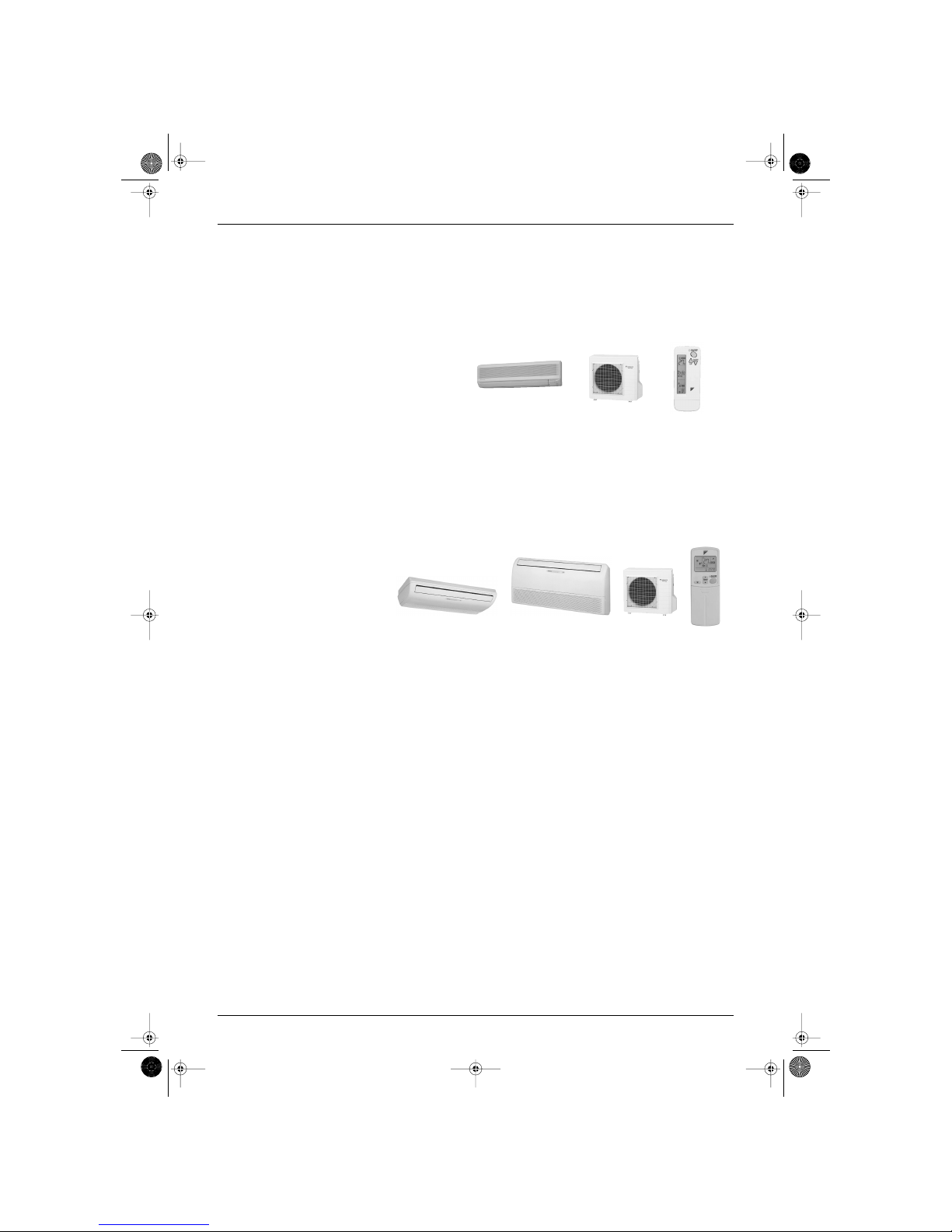
Inverter Pair
FTXD-J, FLX-J / RXD-J
Series
Wall Mounted Type
Heat Pump
Indoor Unit
FTXD50JV1B
FTXD60JV1B
FTXD71JV1B
Outdoor Unit
RXD50JV1B
RXD60JV1B
RXD71JV1B
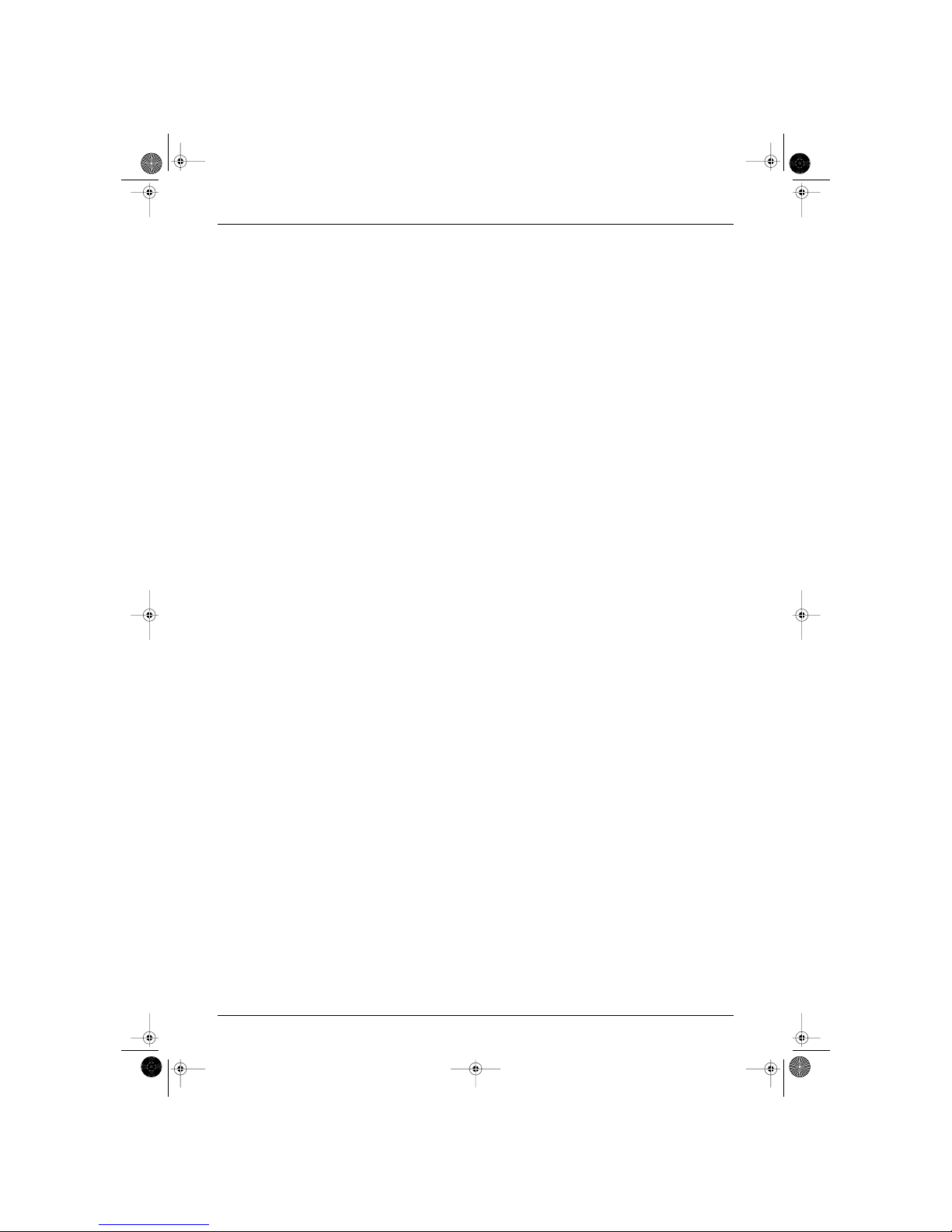
Floor / Ceiling
Suspended Dual Type
Heat Pump
Indoor Unit
FLX50JV1B
FLX60JV1B
Outdoor Unit
RXD50JV1B
RXD60JV1B
SiBE04-101.book Page i Monday, October 15, 2001 3:08 PM

SiBE04-101
ii Table of Contents
1. Introduction .............................................................................................v
1.1 Safety Cautions ....................................................................................... v
Part 1 List of Function .................................................................1
1. Functions.................................................................................................2
1.1 List of Functions ..................................................................................... 2
Part 2 Specifications.....................................................................3
1. Specifications..........................................................................................4
1.1 Wall Mounted Type.................................................................................. 4
1.2 Floor / Ceiling Suspended Dual Type...................................................... 6
Part 3 Printed Circuit Board Connector Wiring Diagram .............7
1. Printed Circuit Board Connector Wiring Diagram and Name..................8
1.1 Name of Connectors for Indoor Unit........................................................ 8
1.2 FTXD50 / 60 / 71J Series ........................................................................ 9
1.3 FLX50 / 60J Series................................................................................ 11
1.4 Name of Connectors for Outdoor Unit................................................... 13
1.5 RXD50 / 60 / 71J Series........................................................................ 14
Part 4 Main Function...................................................................17
1. General Functions.................................................................................18
1.1 Functions of Thermistors....................................................................... 18
1.2 Operating Modes................................................................................... 19
1.3 Frequency Principle............................................................................... 20
1.4 Defrost Control ...................................................................................... 21
1.5 Forced Operation Mode......................................................................... 23
1.6 Flap Control........................................................................................... 24
1.7 Fan Speed Control for Indoor Units....................................................... 27
1.8 Fan Speed Control for Outdoor Units.................................................... 28
1.9 Outdoor Unit Silent Operation ............................................................... 29
1.10 General Functions ................................................................................. 30
1.11 Inverter Powerful Operation................................................................... 32
1.12 Home Leave Operation ......................................................................... 33
1.13 Automatic Operation.............................................................................. 34
1.14 Input Current Control............................................................................. 35
1.15 Freeze up Prevention Function in Cooling ............................................ 36
1.16 Peak-Cut Control Function .................................................................... 37
1.17 4-Way Valve Function Compensation ................................................... 38
1.18 Compressor Protection Function........................................................... 39
1.19 Wet Operation Protection I (Securing of Differential Pressure
and Blown Air Temperature).................................................................. 40
1.20 Wet Operation Protection II (Protection from Differential Pressure)...... 41
1.21 Dew Prevention Function ...................................................................... 42
1.22 Setting for Long Piping .......................................................................... 43
1.23 On-site Setting Jumper Wire ................................................................. 44
SiBE04-101.book Page ii Monday, October 15, 2001 3:08 PM

SiBE04-101
Table of Contents iii
Part 5 System Configuration.......................................................45
1. Instruction..............................................................................................46
1.1 FTXD50 / 60 / 71J ................................................................................. 46
1.2 FLX50 / 60J ........................................................................................... 65
Part 6 Service Diagnosis.............................................................81
1. Caution for Diagnosis............................................................................82
1.1 Troubleshooting with the Operation Lamp............................................. 82
1.2 Troubleshooting with the LED Indication............................................... 83
2. Problem Symptoms and Measures.......................................................84
3. Service Check Function ........................................................................85
3.1 ARC417 Series...................................................................................... 85
3.2 ARC423 Series...................................................................................... 86
4. Troubleshooting ....................................................................................87
4.1 Indoor Units ........................................................................................... 87
4.2 Outdoor Units ........................................................................................ 88
4.3 Faulty PCB ............................................................................................ 89
4.4 Operation Shutdown Due to High-Pressure Control
or Freeze-Up Protection (Thermistor Activation).................................. 90
4.5 Operation Halt Due to Fan Motor (DC Motor) or Related Abnormality
[Wall Mounted Type].............................................................................. 91
4.6 Operation Halt Due to Fan Motor (AC Motor) or Related Abnormality
(Floor / Ceiling Suspended Dual Type). ................................................ 93
4.7 Operation Halt Due to Detection of Thermistor
or Related Abnormality.......................................................................... 94
4.8 Faulty Indoor Unit PCB.......................................................................... 95
4.9 Faulty Indoor Unit PCB.......................................................................... 96
4.10 Power Supply Abnormalities or Faulty Indoor PCB............................... 97
4.11 Signal Transmission Error (between Indoor and Outdoor Units)........... 98
4.12 Faulty Indoor / Outdoor Power Supply Specification............................. 99
4.13 Operation Halt Due to High Pressure Control for Cooling Operation .. 100
4.14 Operation Halt Due to Discharge Pipe Temperature Control .............. 101
4.15 Interrupt Due to OL Action or Thermal Fuse Blow-Out........................ 102
4.16 Compressor Seizing ............................................................................ 104
4.17 DC Fan Seizing ................................................................................... 105
4.18 Operation Halt Due to Detection of Input Over Current....................... 106
4.19 Operation Halt Due to Position Detection Sensor ............................... 108
4.20 Operation Halt Due to Detection of CT Error....................................... 109
4.21 Output Overcurrent.............................................................................. 110
4.22 Operation Halt Due to Thermistor Error or Disconnection Detection... 112
4.23 Operation Halt Due to Detection of Insufficient Gas............................ 113
4.24 Detection of Low Voltage (LVP) .......................................................... 115
4.25 Faulty Outdoor Unit PCB..................................................................... 116
4.26 Faulty Outdoor Unit PCB and Transmitting/Receiving Circuit ............. 117
5. Checks ................................................................................................119
5.1 How to Check ...................................................................................... 119
SiBE04-101.book Page iii Monday, October 15, 2001 3:08 PM
SiBE04-101
iv Table of Contents
Part 7 Removal Procedure ........................................................129
1. For RXD50·60·71J ..............................................................................130
1.1 Removal of Outer Panels and Fan Motor............................................ 130
1.2 Removal of Electrical Box.................................................................... 134
1.3 Removal of Partition Board and Reactor............................................. 140
1.4 Removal of Sound Insulation for Compressor..................................... 142
1.5 Removal of 4-way Valve...................................................................... 143
1.6 Removal of Motorized Valve................................................................ 144
1.7 Removal of Compressor...................................................................... 145
Part 8 Appendix.........................................................................147
1. Piping Diagrams..................................................................................148
1.1 Indoor Units ......................................................................................... 148
1.2 Outdoor Units ...................................................................................... 149
2. Wiring Diagrams..................................................................................150
2.1 Indoor Units ......................................................................................... 150
2.2 Outdoor Units ...................................................................................... 151
Index .............................................................................................i
Drawings & Flow Charts ...............................................................iii
SiBE04-101.book Page iv Monday, October 15, 2001 3:08 PM
SiBE04-101 Introduction
v
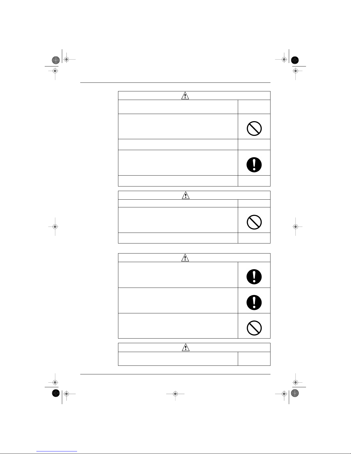
1. Introduction
1.1 Safety Cautions
Cautions and
Warnings
Be sure to read the following safety cautions before conducting repair work.
The caution items are classified into “
Warning
” and “
Caution
”. The “
Warning
” items are
especially important since they can lead to death or serious injury if they are not followed closely. The
“
Caution
” items can also lead to serious accidents under some conditions if they are not followed.
Therefore, be sure to observe all the safety caution items described below.
About the pictograms
This symbol indicates an item for which caution must be exercised.
The pictogram shows the item to which attention must be paid.
This symbol indicates a prohibited action.
The prohibited item or action is shown inside or near the symbol.
This symbol indicates an action that must be taken, or an instruction.
The instruction is shown inside or near the symbol.
After the repair work is complete, be sure to conduct a test operation to ensure that the equipment
operates normally, and explain the cautions for operating the product to the customer
1.1.1 Cautions in Repair
Warning
Be sure to disconnect the power cable plug from the plug socket before disassembling
the equipment for a repair.
Working on the equipment that is connected to a power supply can cause an electrical
shook.
If it is necessary to supply power to the equipment to conduct the repair or inspecting the
circuits, do not touch any electrically charged sections of the equipment.
If the refrigerant gas discharges during the repair work, do not touch the discharging
refrigerant gas.
The refrigerant gas can cause frostbite.
When disconnecting the suction or discharge pipe of the compressor at the welded
section, release the refrigerant gas completely at a well-ventilated place first.
If there is a gas remaining inside the compressor, the refrigerant gas or refrigerating
machine oil discharges when the pipe is disconnected, and it can cause injury.
If the refrigerant gas leaks during the repair work, ventilate the area. The refrigerant gas
can generate toxic gases when it contacts flames.
The step-up capacitor supplies high-voltage electricity to the electrical components of the
outdoor unit.
Be sure to discharge the capacitor completely before conducting repair work.
A charged capacitor can cause an electrical shock.
Do not start or stop the air conditioner operation by plugging or unplugging the power
cable plug.
Plugging or unplugging the power cable plug to operate the equipment can cause an
electrical shock or fire.
SiBE04-101.book Page v Monday, October 15, 2001 3:08 PM
Introduction SiBE04-101
vi
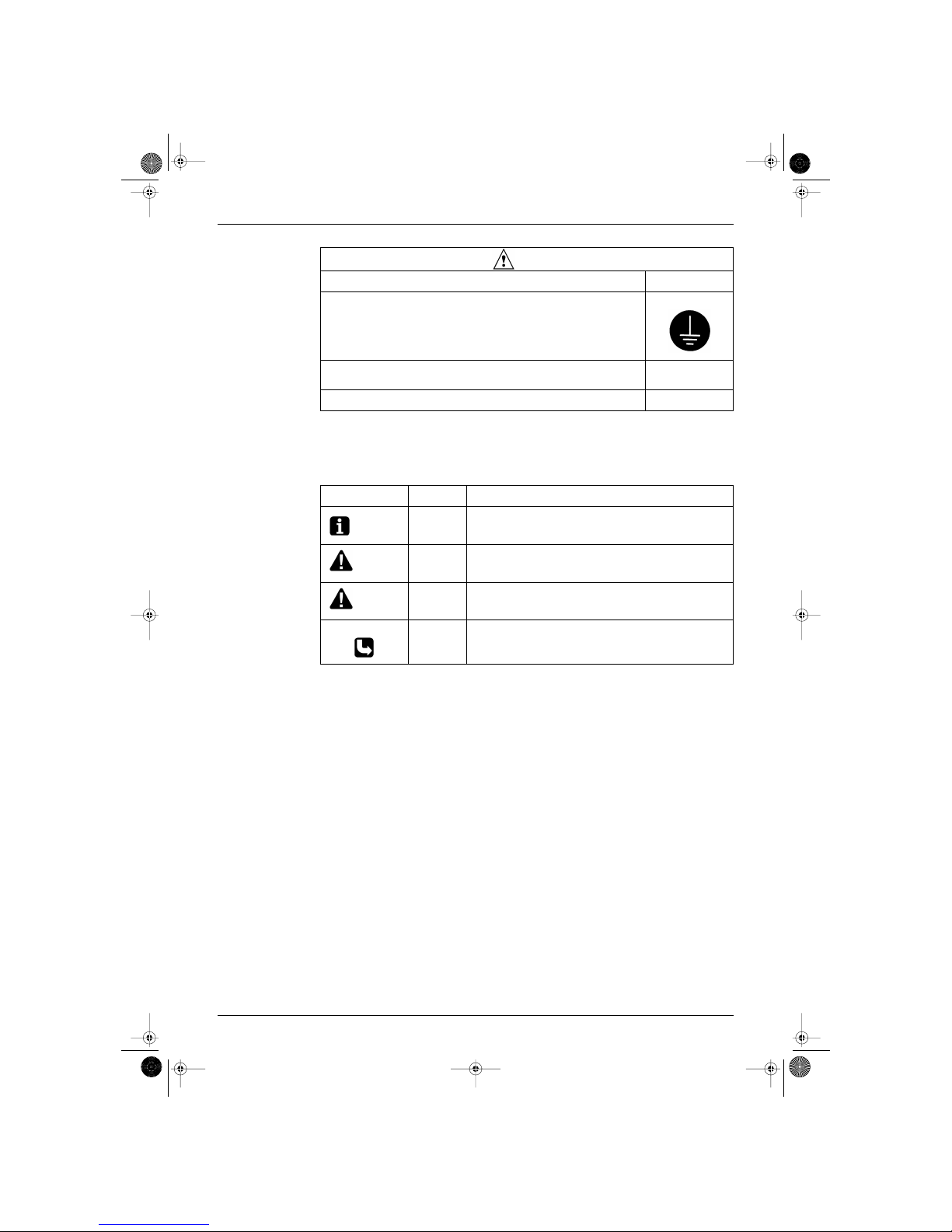
1.1.2 Cautions Regarding Products after Repair
Caution
Do not repair the electrical components with wet hands.
Working on the equipment with wet hands can cause an electrical shock.
Do not clean the air conditioner by splashing water.
Washing the unit with water can cause an electrical shock.
Be sure to provide the grounding when repairing the equipment in a humid or wet place,
to avoid electrical shocks.
Be sure to turn off the power switch and unplug the power cable when cleaning the
equipment.
The internal fan rotates at a high speed, and cause injury.
Do not tilt the unit when removing it.
The water inside the unit can spill and wet the furniture and floor.
Be sure to check that the refrigerating cycle section has cooled down sufficiently before
conducting repair work.
Working on the unit when the refrigerating cycle section is hot can cause burns.
Use the welder in a well-ventilated place.
Using the welder in an enclosed room can cause oxygen deficiency.
Warning
Be sure to use parts listed in the service parts list of the applicable model and appropriate
tools to conduct repair work. Never attempt to modify the equipment.
The use of inappropriate parts or tools can cause an electrical shock, excessive heat
generation or fire.
When relocating the equipment, make sure that the new installation site has sufficient
strength to withstand the weight of the equipment.
If the installation site does not have sufficient strength and if the installation work is not
conducted securely, the equipment can fall and cause injury.
Be sure to install the product correctly by using the provided standard installation frame.
Incorrect use of the installation frame and improper installation can cause the equipment
to fall, resulting in injury.
For integral units only
Be sure to install the product securely in the installation frame mounted on a window
frame.
If the unit is not securely mounted, it can fall and cause injury.
For integral units only
Be sure to use an exclusive power circuit for the equipment, and follow the technical
standards related to the electrical equipment, the internal wiring regulations and the
instruction manual for installation when conducting electrical work.
Insufficient power circuit capacity and improper electrical work can cause an electrical
shock or fire.
Be sure to use the specified cable to connect between the indoor and outdoor units.
Make the connections securely and route the cable properly so that there is no force
pulling the cable at the connection terminals.
Improper connections can cause excessive heat generation or fire.
SiBE04-101.book Page vi Monday, October 15, 2001 3:08 PM
SiBE04-101 Introduction
vii
1.1.3 Inspection after Repair
When connecting the cable between the indoor and outdoor units, make sure that the
terminal cover does not lift off or dismount because of the cable.
If the cover is not mounted properly, the terminal connection section can cause an
electrical shock, excessive heat generation or fire.
Do not damage or modify the power cable.
Damaged or modified power cable can cause an electrical shock or fire.
Placing heavy items on the power cable, and heating or pulling the power cable can
damage the cable.
Do not mix air or gas other than the specified refrigerant (R22) in the refrigerant system.
If air enters the refrigerating system, an excessively high pressure results, causing
equipment damage and injury.
If the refrigerant gas leaks, be sure to locate the leak and repair it before charging the
refrigerant. After charging refrigerant, make sure that there is no refrigerant leak.
If the leak cannot be located and the repair work must be stopped, be sure to perform
pump-down and close the service valve, to prevent the refrigerant gas from leaking into
the room. The refrigerant gas itself is harmless, but it can generate toxic gases when it
contacts flames, such as fan and other heaters, stoves and ranges.
When replacing the coin battery in the remote controller, be sure to disposed of the old
battery to prevent children from swallowing it.
If a child swallows the coin battery, see a doctor immediately.
Warning
Caution
Installation of a leakage breaker is necessary in some cases depending on the
conditions of the installation site, to prevent electrical shocks.
Do not install the equipment in a place where there is a possibility of combustible gas
leaks.
If a combustible gas leaks and remains around the unit, it can cause a fire.
Be sure to install the packing and seal on the installation frame properly.
If the packing and seal are not installed properly, water can enter the room and wet the
furniture and floor.
For integral units only
Warning
Check to make sure that the power cable plug is not dirty or loose, then insert the plug
into a power outlet all the way.
If the plug has dust or loose connection, it can cause an electrical shock or fire.
If the power cable and lead wires have scratches or deteriorated, be sure to replace
them.
Damaged cable and wires can cause an electrical shock, excessive heat generation or
fire.
Do not use a joined power cable or extension cable, or share the same power outlet with
other electrical appliances, since it can cause an electrical shock, excessive heat
generation or fire.
Caution
Check to see if the parts and wires are mounted and connected properly, and if the
connections at the soldered or crimped terminals are secure.
Improper installation and connections can cause excessive heat generation, fire or an
electrical shock.
SiBE04-101.book Page vii Monday, October 15, 2001 3:08 PM
Introduction SiBE04-101
viii
1.1.4 Using Icons
Icons are used to attract the attention of the reader to specific information. The meaning of each icon is
described in the table below:
1.1.5 Using Icons List
If the installation platform or frame has corroded, replace it.
Corroded installation platform or frame can cause the unit to fall, resulting in injury.
Check the grounding, and repair it if the equipment is not properly grounded.
Improper grounding can cause an electrical shock.
Be sure to measure the insulation resistance after the repair, and make sure that the
resistance is 1 Mohm or higher.
Faulty insulation can cause an electrical shock.
Be sure to check the drainage of the indoor unit after the repair.
Faulty drainage can cause the water to enter the room and wet the furniture and floor.
Caution
Icon Type of
Information
Description
Note:
Note A “note” provides information that is not indispensable, but may
nevertheless be valuable to the reader, such as tips and tricks.
Caution
Caution A “caution” is used when there is danger that the reader, through
incorrect manipulation, may damage equipment, loose data, get an
unexpected result or has to restart (part of) a procedure.
Warning
Warning A “warning” is used when there is danger of personal injury.
Reference A “reference” guides the reader to other places in this binder or in this
manual, where he/she will find additional information on a specific topic.
SiBE04-101.book Page viii Monday, October 15, 2001 3:08 PM

SiBE04-101
List of Function 1
Part 1
List of Function
1. Functions.................................................................................................2
1.1 List of Functions ..................................................................................... 2
SiBE04-101.book Page 1 Monday, October 15, 2001 3:08 PM
Functions SiBE04-101
2 List of Function
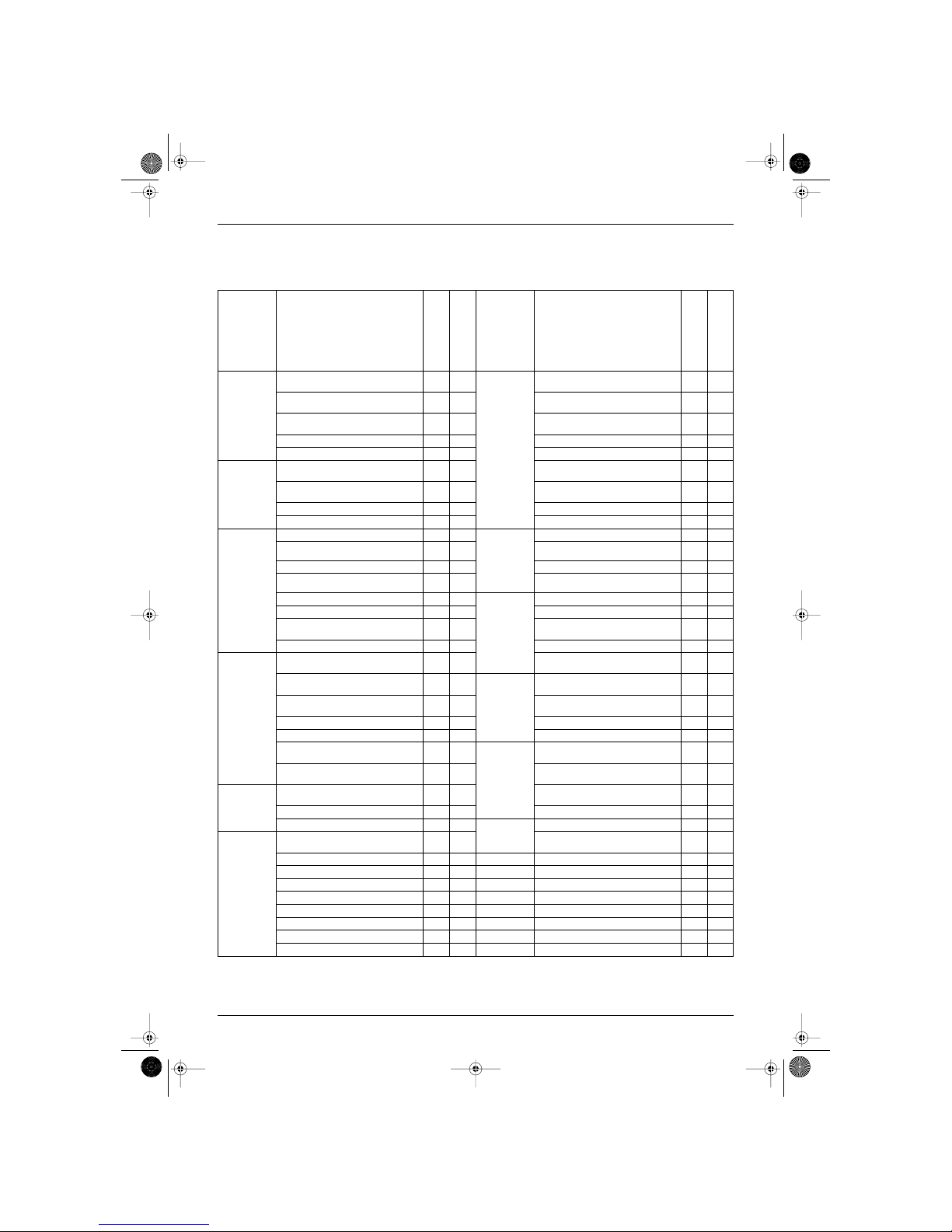
1. Functions
1.1 List of Functions
Note:
: Holding Functions
— : No Functions
Category Functions
FTXD50·60·71JV1B
RXD50·60·71JV1B
FLX50·60JV1B
RXD50·60JV1B
Category Functions
FTXD50·60·71JV1B
RXD50·60·71JV1B
FLX50·60JV1B
RXD50·60JV1B
Basic
Function
Inverter (with Inverter Power Control)
Health
Health &
Clean
Air Purifying Filter with Bacteriostatic,
Virustatic & Deodorizing Functions
Operation Limit for Cooling (˚C) -10
~46
-10
~46
Longlife Filter
——
Operation Limit for Heating (˚C) -15
~18
-15
~18
Ultra-Longlife Filter (Option)
——
Microprocessor Control
Photocatalytic Deodorizing Filter — —
PAM Control
Photocatalytic Filter with UV Lamp — —
Compressor Oval Scroll Compressor (DAIKIN
SCROLL)
——
Mold Proof Air Filter
Swing Compressor (DAIKIN
ROTARY)
Washable Grille
—
Rotary Compressor — — Filter Cleaning Indicator — —
Reluctance DC Motor
Good-Sleep Cooling Operation — —
Comfortable
Airflow
Dual Flaps — — Timer 72-Hour On/Off Timer — —
Power-Airflow Dual Flaps
5 Step
—
24-Hour On/Off Timer
Power-Airflow Diffuser
— Night Set Mode
Wide-Angle Louvers
5 Step
Just Fit Thermostatic Timer
——
Vertical Auto-Swing (Up and Down)
Worry Free
“Reliability &
Durability”
Auto-Restart (after Power Failure)
Horizontal Auto-Swing (Right and Left)
— Self-Diagnosis (Digital, LED) Display
3-D Airflow
—
The Remote Controller Loss
Prevention with the Chain (Option)
3-Step Airflow (H/P Only) — — Wiring-Error Check — —
Comfortable
Control
Comfort
Control
Auto Fan Speed
Anticorrosion Treatment of Outdoor
Heat Exchanger
Silent Operation Control (Automatic)
——
Flexibility Multi-Split / Split Type Compatible
Indoor Unit
Outdoor Unit Silent Operation
(Manual)
Flexible Voltage Correspondence
Intelligent Eye — — High Ceiling Application — —
Quick Warming Function
Chargeless 10m 10m
Hot-Start Function
Remote
Control
5-Rooms Centralized Controller
(Option)
Automatic Defrosting
Remote Control Adaptor (Option)
(Normal Open-Pulse)
Operation Automatic Operation
Remote Control Adaptor (Normal
Open Contact)
Programme Dry Function
Dlll-NET Compatible (Adaptor)
Fan Only — — Remote
Controller
Wireless
Lifestyle
Convenience
New Powerful Operation (NonInverter)
——
Wired
——
Inverter Powerful Operation
Priority-Room Setting — —
Laundry Programme Operation — —
Home Leave Operation
Power Selection — —
Indoor Unit On/Off Switch
Signal Reception Indicator
Temperature Display — —
SiBE04-101.book Page 2 Monday, October 15, 2001 3:08 PM

SiBE04-101
Specifications 3
Part 2
Specifications
1. Specifications..........................................................................................4
1.1 Wall Mounted Type.................................................................................. 4
1.2 Floor / Ceiling Suspended Dual Type...................................................... 6
SiBE04-101.book Page 3 Monday, October 15, 2001 3:08 PM
Specifications SiBE04-101
4 Specifications
1. Specifications
1.1 Wall Mounted Type
230V, 50Hz
Notes: MAX. interunit piping length: 30m
MAX. interunit height difference: 20m
Amount of additional charge of refrigerant 20g/m for piping length exceeding 10m
The data are based on the conditions shown in the table below.
Models
Indoor Units FTXD50JV1B FTXD60JV1B
Outdoor Units
RXD50JV1B RXD60JV1B
Cooling Heating Cooling Heating
Capacity
Rated (Min.~Max.)
kW 5.2 (0.9~5.8) 6.5 (0.9~8.0) 6.2 (0.9~7.0) 7.2 (0.9~8.5)
Btu/h 17,800 (3,100~19,800) 22,200 (3,100~27,300) 21,200 (3,100~24,000) 24,600 (3,100~29,000)
kcal/h 4,470 (775~4,990) 5,590 (775~6,880) 5,330 (775~6,020) 6,190 (775~7,310)
Moisture Removal L/h 2.9 — 3.9 —
Running Current (Rated) A 7.6 8.4 9.7 9.3
Power Consumption Rated
(Min.~Max.)
W 1,730 (450~2,300) 1,910 (450~2,800) 2,210 (450~2,900) 2,120 (450~3,300)
Power Factor % 99.0 98.9 99.1 99.1
COP W/W 3.01 3.40 2.81 3.40
Piping
Connections
Liquid mm φ6.4 φ6.4
Gas mm φ12.7 φ15.9
Drain mm φ18.0 φ18.0
Heat Insulation Both Liquid and Gas Pipes Both Liquid and Gas Pipes
Indoor Units FTXD50JV1B FTXD60JV1B
Front Panel Color Almond White Almond White
Air Flow Rate
m³/min
(cfm)
H 12.3 (434) 14.9 (526) 13.0 (459) 16.5 (582)
M 10.7 (378) 12.8 (452) 11.5 (406) 13.7 (484)
L 9.1 (321) 10.5 (371) 9.9 (349) 11.1 (392)
Fan
Type Cross Flow Fan Cross Flow Fan
Motor Output W 54 54
Speed Steps 5 Steps and Auto 5 Steps and Auto
Air Direction Control Right, Left, Horizontal and Downward Right, Left, Horizontal and Downward
Air Filter Removable / Washable / Mildew Proof Removable / Washable / Mildew Proof
Running Current (Rated) A 0.18 0.17 0.20 0.20
Power Consumption (Rated) W 40 38 45 45
Power Factor % 96.6 97.2 97.8 97.8
Temperature Control Microcomputer Control Microcomputer Control
Dimensions (H×W×D) mm 298×1,050×190 298×1,050×190
Packaged Dimensions (W×D×H) mm 1,183×367×289 1,183×367×289
Weight kg 12 12
Gross Weight kg 16 16
Operation
Sound
H/M/L dBA 44/40/35 42/37/32 45/41/37 44/39/34
Outdoor Units RXD50JV1B RXD60JV1B
Casing Color Ivory White Ivory White
Compressor
Type Hermetically Sealed Swing Type Hermetically Sealed Swing Type
Model 2YC32YXD 2YC45ZXD
Motor Output W 1,500 1,900
Refrigerant
Oil
Model SUNISO 4GSD.I. SUNISO 4GSD.I.
Charge L 0.4 0.75
Refrigerant
Model R22 R22
Charge kg 1.15 1.60
Air Flow Rate
(H/L)
m³/min 48.0/36.0 42.6/31.4 46.5/36.5 45.6/35.0
cfm 1,694/1,271 1,504/1,108 1,641/1,288 1,610/1,236
Fan
Type Propeller Propeller
Motor Output W 53 53
Running Current (Rated) A 7.42 8.23 9.50 9.10
Power Consumption (Rated) W 1,690 1,872 2,165 2,075
Power Factor % 99.0 98.9 99.1 99.1
Starting Current A 8.4 9.7
Dimensions (H×W×D) mm 735×825×300 735×825×300
Packaged Dimensions (W×D×H) mm 929×359×784 929×359×784
Weight kg 44 51
Gross Weight kg 48 55
Operation Sound dBA 47 48 48 49
Drawing No. 3D029183 3D029184
Conversion Formulae
kcal/h=kW×860
Btu/h=kW×3414
cfm=m³/min×35.3
Cooling Heating Piping Length
Indoor ; 27˚CDB/19˚CWB
Outdoor ; 35˚CDB/24˚CWB
Indoor ; 20˚CDB
Outdoor ; 7˚CDB/6˚CWB
7.5m
SiBE04-101.book Page 4 Monday, October 15, 2001 3:08 PM
SiBE04-101 Specifications
Specifications 5
230V, 50Hz
Notes: MAX. interunit piping length: 30m
MAX. interunit height difference: 20m
Amount of additional charge of refrigerant 20g/m for piping length exceeding 10m
The data are based on the conditions shown in the table below.
The Fan Control of the Outdoor Unit on the Outdoor Conditions Less than 10˚C (In Cool Operation)
Models
Indoor Units FTXD71JV1B
Outdoor Units
RXD71JV1B
Cooling Heating
Capacity
Rated (Min.~Max.)
kW 7.1 (0.9~8.0) 8.5 (0.9~9.5)
Btu/h 24,300 (3,100~27,300) 29,100 (3,100~32,500)
kcal/h 6,100 (775~6,880) 7,310 (775~8,170)
Moisture Removal L/h 4.5 —
Running Current (Rated) A 11.5 12.0
Power Consumption Rated
(Min.~Max.)
W 2,630 (450~3,450) 2,740 (450~3,800)
Power Factor % 99.4 99.3
COP W/W 2.70 3.10
Piping
Connections
Liquid mm φ9.5
Gas mm φ15.9
Drain mm φ18.0
Heat Insulation Both Liquid and Gas Pipes
Indoor Units FTXD71JV1B
Front Panel Color Almond White
Air Flow Rate
m³/min
(cfm)
H 13.7 (484) 17.3 (611)
M 11.8 (417) 14.1 (498)
L 9.9 (349) 11.1 (392)
Fan
Type Cross Flow Fan
Motor Output W 54
Speed Steps 5 Steps and Auto
Air Direction Control Right, Left, Horizontal and Downward
Air Filter Removable / Washable / Mildew Proof
Running Current (Rated) A 0.22 0.22
Power Consumption (Rated) W 50 50
Power Factor % 98.8 98.8
Temperature Control Microcomputer Control
Dimensions (H×W×D) mm 298×1,050×190
Packaged Dimensions (W×D×H) mm 1,183×367×289
Weight kg 12
Gross Weight kg 16
Operation
Sound
H/M/L dBA 46/42/37 46/40/34
Outdoor Units RXD71JV1B
Casing Color Ivory White
Compressor
Type Hermetically Sealed Swing Type
Model 2YC63ZXD
Motor Output W 1,900
Refrigerant
Oil
Model SUNISO 4GSD.I.
Charge L 0.65
Refrigerant
Model R22
Charge kg 1.70
Air Flow Rate
(H/L)
m³/min 51.5/41.5 45.6/35.6
cfm 1,818/1,465 1,610/1,257
Fan
Type Propeller
Motor Output W 53
Running Current (Rated) A 11.28 11.78
Power Consumption (Rated) W 2,580 2,690
Power Factor % 99.4 99.3
Starting Current A 12.0
Dimensions (H×W×D) mm 735×825×300
Packaged Dimensions (W×D×H) mm 929×359×784
Weight kg 53
Gross Weight kg 57
Operation Sound dBA 52 52
Drawing No. 3D029185
Conversion Formulae
kcal/h=kW×860
Btu/h=kW×3414
cfm=m³/min×35.3
Cooling Heating Piping Length
Indoor ; 27˚CDB/19˚CWB
Outdoor ; 35˚CDB/24˚CWB
Indoor ; 20˚CDB
Outdoor ; 7˚CDB/6˚CWB
7.5m
RXD50JV1B RXD60JV1B RXD71JV1B
Fan Motor Rotation Speed (rpm) LL 280 320 320
LLL 200 200 200
Air Flow Rate (m³/min) LL 17.0 19.0 19.0
LLL 11.0 11.0 11.0
The Outdoor Temperature (˚C) LL 0˚C~10˚C 0˚C~10˚C 0˚C~10˚C
LLL Less than 0˚C Less than 0˚C Less than 0˚C
SiBE04-101.book Page 5 Monday, October 15, 2001 3:08 PM
Specifications SiBE04-101
6 Specifications
1.2 Floor / Ceiling Suspended Dual Type
230V 50Hz
Notes: MAX. interunit piping length: 30m
MAX. interunit height difference: 20m
Amount of additional charge of refrigerant 20g/m for piping length exceeding 10m
The data are based on the conditions shown in the table below.
The Fan Control of the Outdoor Unit on the Outdoor Conditions Less than 10˚C (In Cool Operation)
Models
Indoor Units FLX50JV1B FLX60JV1B
Outdoor Units
RXD50JV1B RXD60JV1B
Cooling Heating Cooling Heating
Capacity
Rated (Min.~Max.)
kW 4.7 (0.9~5.3) 6.1 (0.9~7.5) 5.7 (0.9~6.5) 6.7 (0.9~8.0)
Btu/h 16,000 (3,100~18,100) 20,800 (3,100~25,600) 19,500 (3,100~22,200) 22,900 (3,100~27,300)
kcal/h 4,040 (775~4,560) 5,250 (775~6,450) 4,900 (775~5,590) 5,760 (775~6,880)
Moisture Removal L/h 2.9 — 3.9 —
Running Current (Rated) A 6.4 8.0 8.7 8.7
Power Consumption Rated
(Min.~Max.)
W 1,470 (450~1,950) 1,820 (450~2,630) 1,990 (450~2,670) 2,000 (450~3,300)
Power Factor % 99.9 98.9 99.5 100.0
COP W/W 3.20 3.35 2.86 3.35
Piping
Connections
Liquid mm φ6.4 φ6.4
Gas mm φ12.7 φ15.9
Drain mm φ18.0 φ18.0
Heat Insulation Both Liquid and Gas Pipes Both Liquid and Gas Pipes
Indoor Units FLX50JV1B FLX60JV1B
Front Panel Color Almond White Almond White
Air Flow Rate
m³/min
(cfm)
H 11.4 (402) 12.1 (427) 12.0 (424) 12.8 (452)
M 9.9 (349) 9.8 (346) 10.6 (374) 10.6 (374)
L 8.5 (300) 7.5 (265) 9.3 (328) 8.4 (297)
Fan
Type Sirocco Fan Sirocco Fan
Motor Output W 34 34
Speed Steps 5 Steps and Auto 5 Steps and Auto
Air Direction Control Right, Left, Horizontal and Downward Right, Left, Horizontal and Downward
Air Filter Removable / Washable / Mildew Proof Removable / Washable / Mildew Proof
Running Current (Rated) A 0.43 0.42 0.45 0.43
Power Consumption (Rated) W 96 96 98 96
Power Factor % 97.1 99.4 94.7 97.1
Temperature Control Microcomputer Control Microcomputer Control
Dimensions (H×W×D) mm 490×1,050×200 490×1,050×200
Packaged Dimensions (W×D×H) mm 1,100×566×284 1,100×566×284
Weight kg 17 17
Gross Weight kg 24 24
Operation
Sound
H/M/L dBA 47/43/39 46/41/35 48/45/41 47/42/37
Outdoor Units RXD50JV1B RXD60JV1B
Casing Color Ivory White Ivory White
Compressor
Type Hermetically Sealed Swing Type Hermetically Sealed Swing Type
Model 2YC32YXD 2YC45ZXD
Motor Output W 1,500 1,900
Refrigerant
Oil
Model SUNISO 4GSD.I. SUNISO 4GSD.I.
Charge L 0.4 0.75
Refrigerant
Model R22 R22
Charge kg 1.15 1.60
Air Flow Rate
(H/L)
m³/min (cfm)
H 48.0 (1,694) 42.6 (1,504) 46.5 (1,641) 45.6 (1,610)
L 36.0 (1,271) 31.4 (1,108) 36.5 (1,288) 35.0 (1,236)
Fan
Type Propeller Propeller
Motor Output W 53 53
Running Current (Rated) A 5.97 7.58 8.25 8.27
Power Consumption (Rated) W 1,374 1,724 1,892 1,904
Power Factor % 100.0 98.9 99.7 100.0
Starting Current A 8.0 8.7
Dimensions (H×W×D) mm 735×825×300 735×825×300
Packaged Dimensions (W×D×H) mm 929×359×784 929×359×784
Weight kg 44 51
Gross Weight kg 48 55
Operation Sound dBA 47 48 48 49
Drawing No. 3D029186 3D029187
Conversion Formulae
kcal/h=kW×860
Btu/h=kW×3414
cfm=m³/min×35.3
Cooling Heating Piping Length
Indoor ; 27˚CDB/19˚CWB
Outdoor ; 35˚CDB/24˚CWB
Indoor ; 20˚CDB
Outdoor ; 7˚CDB/6˚CWB
7.5m
RXD50JV1B RXD60JV1B
Fan Motor Rotation Speed (rpm) LL 280 320
LLL 200 200
Air Flow Rate (m³/min) LL 17.0 19.0
LLL 11.0 11.0
The Outdoor Temperature (˚C) LL 0˚C~10˚C 0˚C~10˚C
LLL Less than 0˚C Less than 0˚C
SiBE04-101.book Page 6 Monday, October 15, 2001 3:08 PM

SiBE04-101
Printed Circuit Board Connector Wiring Diagram 7
Part 3
Printed Circuit Board
Connector Wiring Diagram
1. Printed Circuit Board Connector Wiring Diagram and Name..................8
1.1 Name of Connectors for Indoor Unit........................................................ 8
1.2 FTXD50 / 60 / 71J Series ........................................................................ 9
1.3 FLX50 / 60J Series................................................................................ 11
1.4 Name of Connectors for Outdoor Unit................................................... 13
1.5 RXD50 / 60 / 71J Series........................................................................ 14
SiBE04-101.book Page 7 Monday, October 15, 2001 3:08 PM
Printed Circuit Board Connector Wiring Diagram and Name SiBE04-101
8 Printed Circuit Board Connector Wiring Diagram
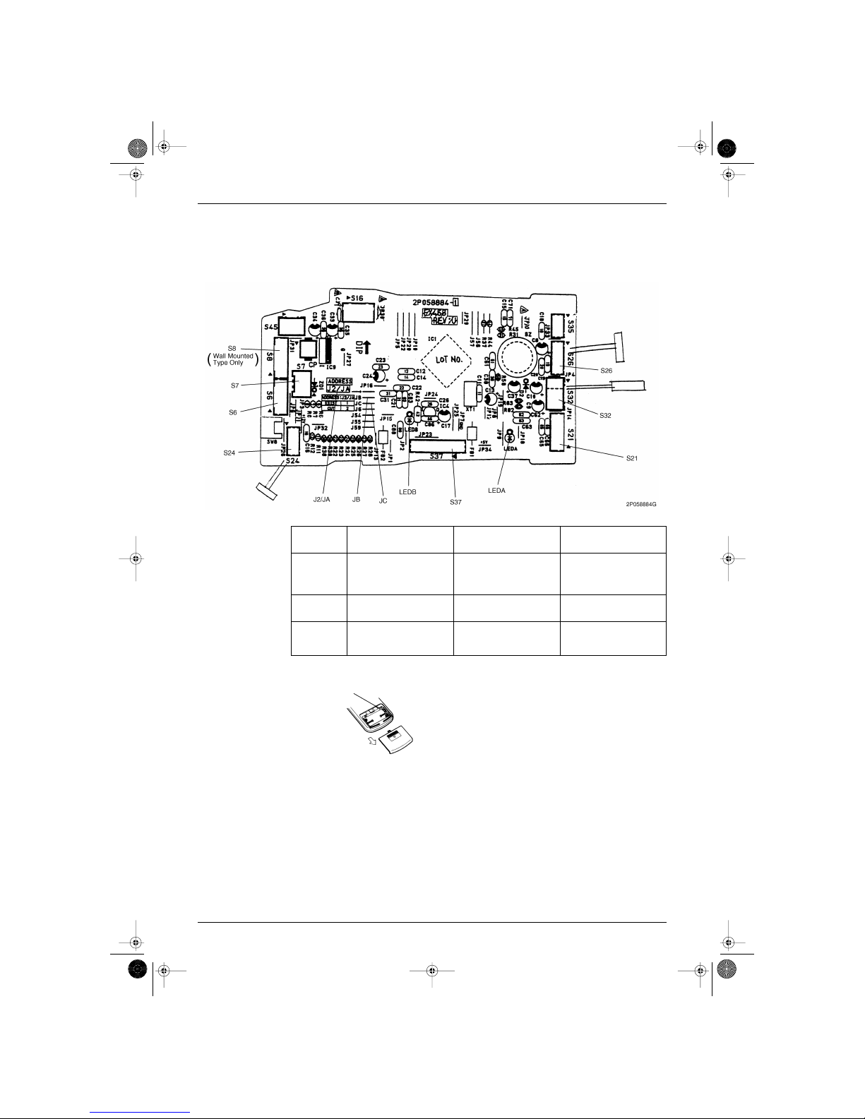
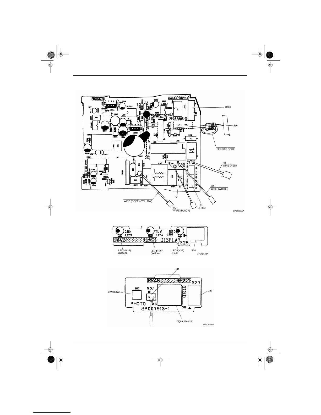
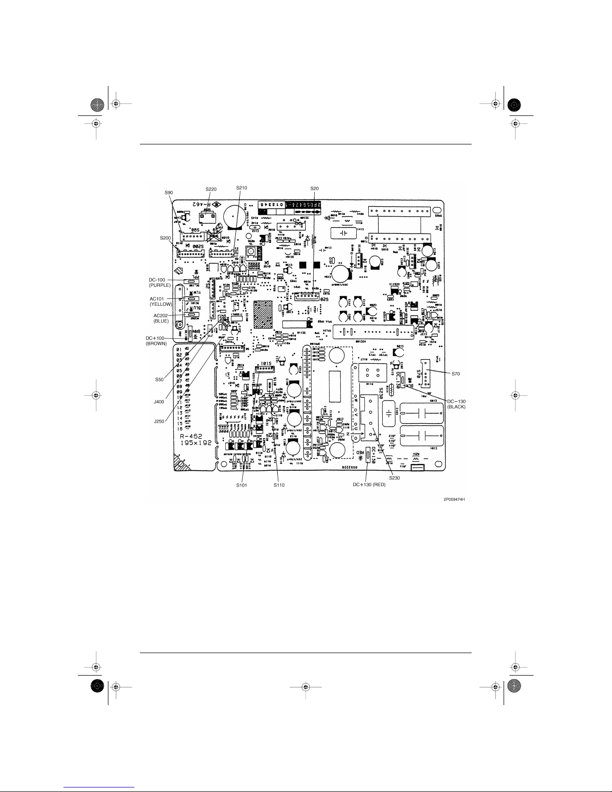
1. Printed Circuit Board Connector Wiring Diagram and
Name
1.1 Name of Connectors for Indoor Unit
Note: Other Designations
1) S6 Connector for Swing Motor (Horizontal Swing)
2) S7 Connector for Fan Motor
3) S8
Wall Mounted
Type Only
Connector for Swing Motor (Vertical Swing)
4) S21 Connector for Centralized Control
5) S24 Connector for Display PCB
6) S25, S27, S36 Connector for Control PCB
7) S26 Connector for Signal Receiver PCB
8) S31, S32 Connector for Room Temp. / Heat Exchanger Thermistor
9) S37 Connector for Power Supply PCB
10) S201 Connector for Fan Motor
1) V1 Varistor
2) J2 / JA Address Setting Jumper
JB Fan Speed Setting Jumper
JC Power Failure Recovery Function.
∗ Refer to the next page for more detail.
3) SW7 (S1W) Operation Switch
4) LED3 (GRN) LED for Operation
5) LED4 (YLW) LED for Timer
6) LED5 (RED) LED for Home Leave Operation
7) LED A, LED B LED for Service Monitor
SiBE04-101.book Page 8 Monday, October 15, 2001 3:08 PM
SiBE04-101 Printed Circuit Board Connector Wiring Diagram and Name
Printed Circuit Board Connector Wiring Diagram 9
1.2 FTXD50 / 60 / 71J Series
1.2.1 Control PCB Detail (PCB 1)
PCB is common for both wall mounted type and floor/ceiling suspended dual type except for the
connectors which are different in their mating plug.
Match the numbers printed at the backside of the wireless remote controller and allocate them to
each indoor unit.
Jumper
(On Indoor PC
Board)
Function When Connected When Cut
J2 / JA When two indoor units are
installed in one room, the two
wireless remote controllers
can be set for different
addresses.
1 () 2 ()
JB Fan speed setting when
compressor is OFF on
thermostat.
Fan speed setting ; Remote
controller setting
Fan rpm is set to “0” <Fan
Stop>
JC Power failure recovery
function
Auto start Unit does not resume
operation after recovering
from a power failure, timer ONOFF setting are cleared.
Address switch (default = "1")
Wireless Remote
Controller
(R1130)
SiBE04-101.book Page 9 Monday, October 15, 2001 3:08 PM
Printed Circuit Board Connector Wiring Diagram and Name SiBE04-101
10 Printed Circuit Board Connector Wiring Diagram
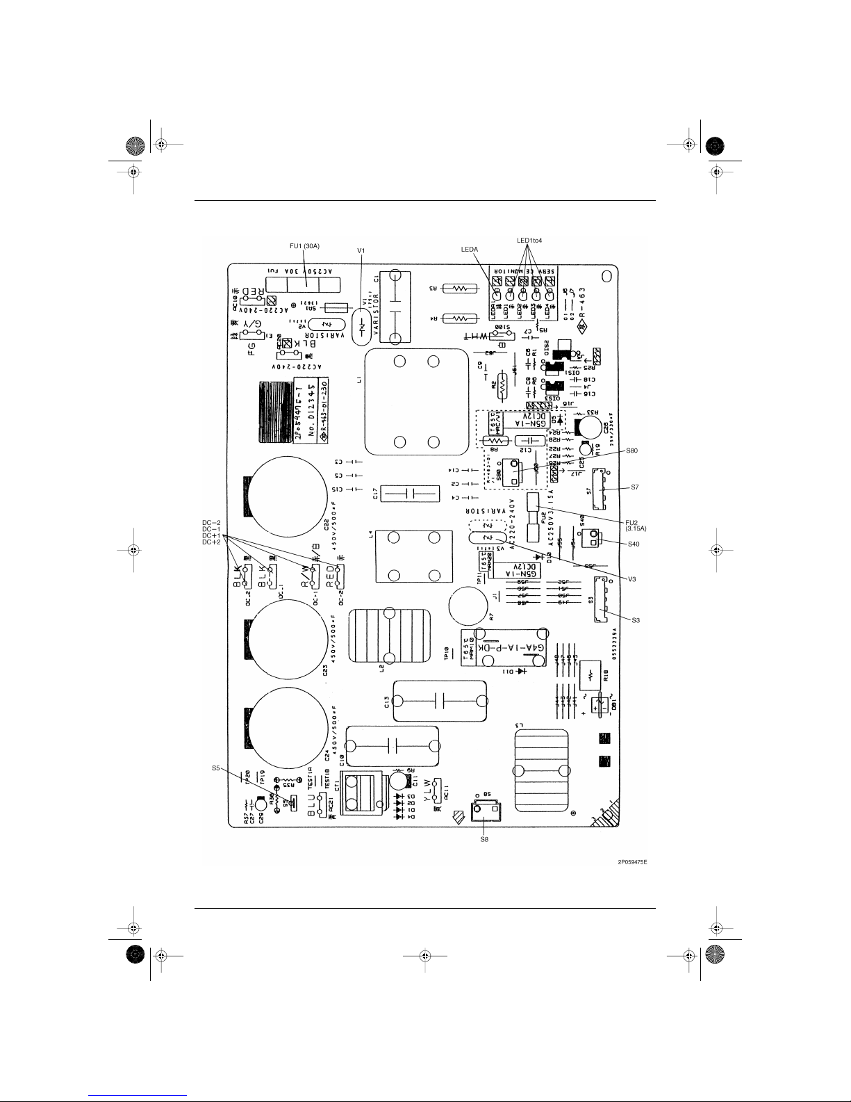
1.2.2 Power Supply PCB Detail (PCB 2)
1.2.3 Display PCB Detail (PCB 3)
1.2.4 Signal Receiver PCB Detail (PCB 4)
SiBE04-101.book Page 10 Monday, October 15, 2001 3:08 PM
SiBE04-101 Printed Circuit Board Connector Wiring Diagram and Name
Printed Circuit Board Connector Wiring Diagram 11
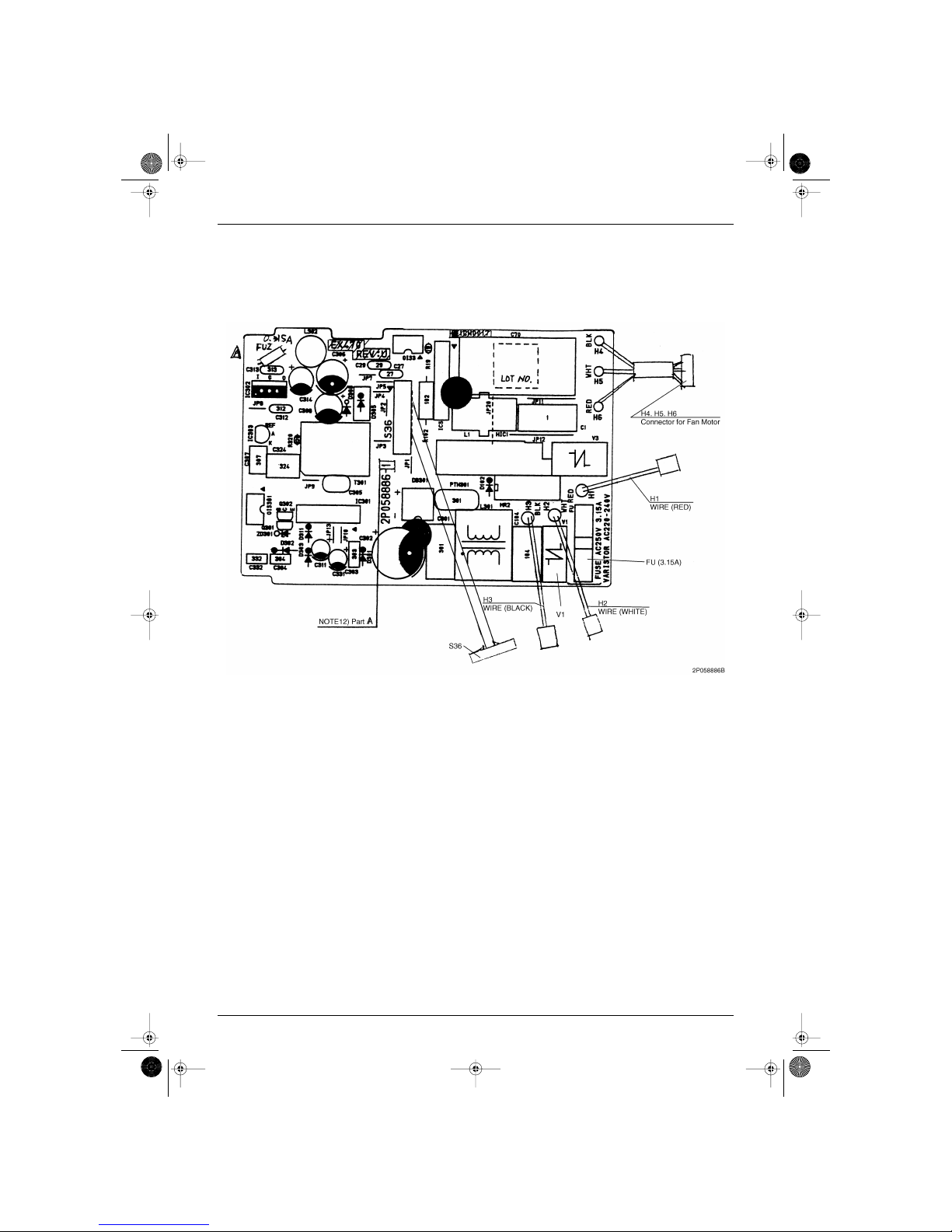
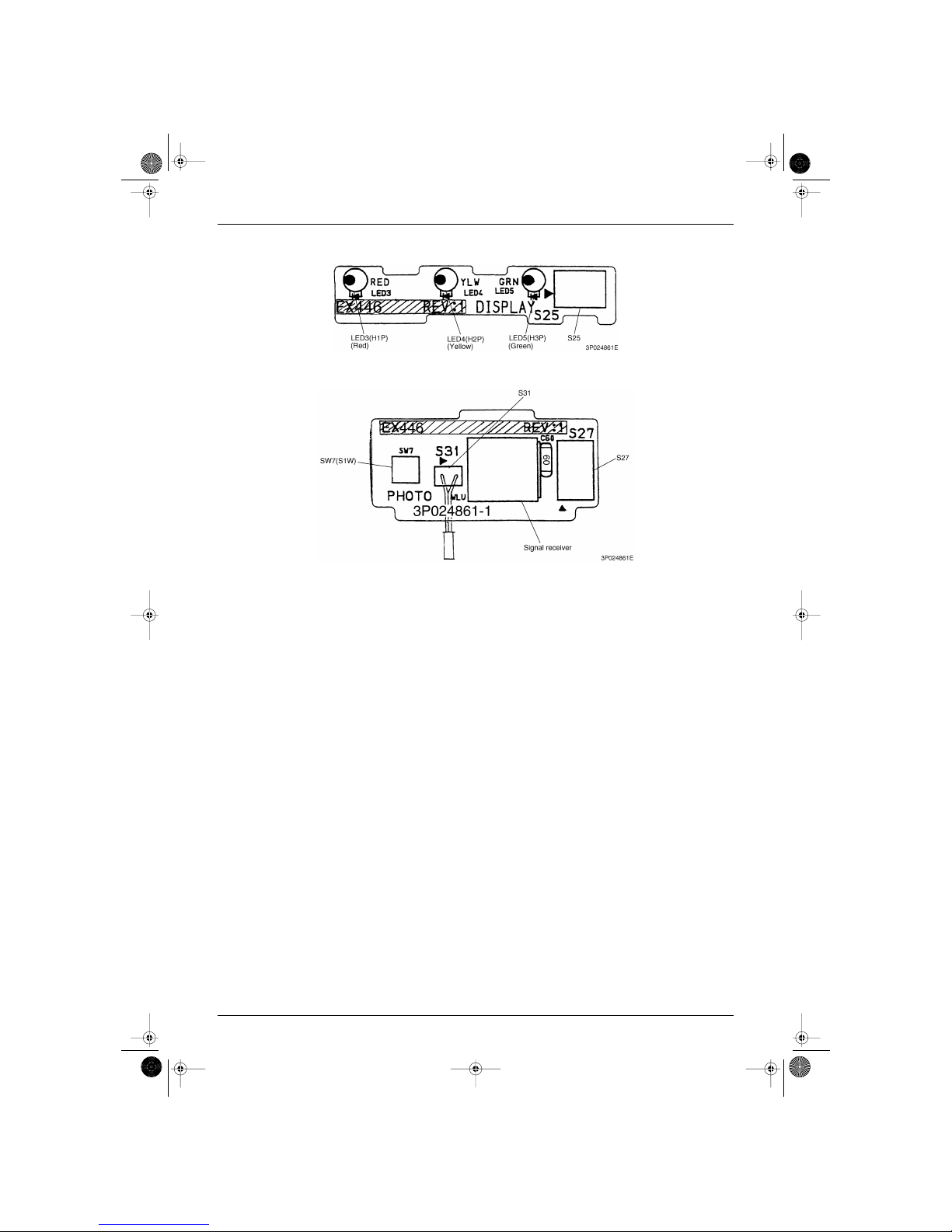
1.3 FLX50 / 60J Series
1.3.1 Control PCB (PCB 1)
Refer to 1.2.1
1.3.2 Power Supply PCB (PCB 2)
SiBE04-101.book Page 11 Monday, October 15, 2001 3:08 PM
Printed Circuit Board Connector Wiring Diagram and Name SiBE04-101
12 Printed Circuit Board Connector Wiring Diagram
1.3.3 Display PCB Detail (PCB 3)
1.3.4 Signal Receiver PCB Detail (PCB 4)
SiBE04-101.book Page 12 Monday, October 15, 2001 3:08 PM
SiBE04-101 Printed Circuit Board Connector Wiring Diagram and Name
Printed Circuit Board Connector Wiring Diagram 13
1.4 Name of Connectors for Outdoor Unit
Note: Other Designation
1) S3, S5, S7, S8 Connector for PCB 2
2) S20, S80 Connector for 4 Way Valve Coil (Heat Pump Only)
3) S40 Connector for TFU (76˚C)
4) S50 Connector for Long Piping Jumper
5) S70 Connector for Fan Motor
6) S90 Connector for Thermistor
7) S101 Connector for Active Module
8) S110 Harness for PCB 1
9) S200, S210, S220 Connector for PCB 1
10) S230 Connector for Compressor Motor (UVWN)
1) V1, V3 Varistor
2) LED A, LED 1 to 4 Service Monitor LED
SiBE04-101.book Page 13 Monday, October 15, 2001 3:08 PM
Printed Circuit Board Connector Wiring Diagram and Name SiBE04-101
14 Printed Circuit Board Connector Wiring Diagram
1.5 RXD50 / 60 / 71J Series
1.5.1 Control PCB
SiBE04-101.book Page 14 Monday, October 15, 2001 3:08 PM
SiBE04-101 Printed Circuit Board Connector Wiring Diagram and Name
Printed Circuit Board Connector Wiring Diagram 15
1.5.2 Filter PCB
SiBE04-101.book Page 15 Monday, October 15, 2001 3:08 PM

Printed Circuit Board Connector Wiring Diagram and Name SiBE04-101
16 Printed Circuit Board Connector Wiring Diagram
SiBE04-101.book Page 16 Monday, October 15, 2001 3:08 PM

SiBE04-101
Main Function 17
Part 4
Main Function
1. General Functions.................................................................................18
1.1 Functions of Thermistors....................................................................... 18
1.2 Operating Modes................................................................................... 19
1.3 Frequency Principle............................................................................... 20
1.4 Defrost Control ...................................................................................... 21
1.5 Forced Operation Mode......................................................................... 23
1.6 Flap Control........................................................................................... 24
1.7 Fan Speed Control for Indoor Units....................................................... 27
1.8 Fan Speed Control for Outdoor Units.................................................... 28
1.9 Outdoor Unit Silent Operation ............................................................... 29
1.10 General Functions ................................................................................. 30
1.11 Inverter Powerful Operation................................................................... 32
1.12 Home Leave Operation ......................................................................... 33
1.13 Automatic Operation.............................................................................. 34
1.14 Input Current Control............................................................................. 35
1.15 Freeze up Prevention Function in Cooling ............................................ 36
1.16 Peak-Cut Control Function .................................................................... 37
1.17 4-Way Valve Function Compensation ................................................... 38
1.18 Compressor Protection Function........................................................... 39
1.19 Wet Operation Protection I (Securing of Differential Pressure
and Blown Air Temperature).................................................................. 40
1.20 Wet Operation Protection II (Protection from Differential Pressure)...... 41
1.21 Dew Prevention Function ...................................................................... 42
1.22 Setting for Long Piping .......................................................................... 43
1.23 On-site Setting Jumper Wire ................................................................. 44
SiBE04-101.book Page 17 Monday, October 15, 2001 3:08 PM
General Functions SiBE04-101
18 Main Function
1. General Functions
1.1 Functions of Thermistors
Location of the
Thermistors
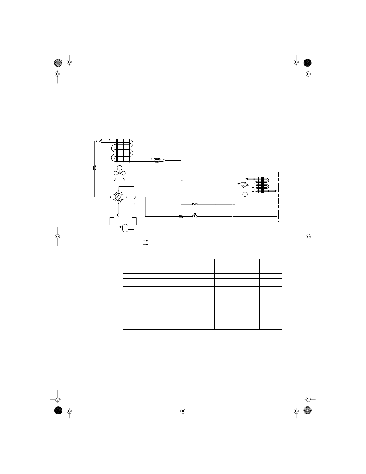
The thermistors on the drawing below are used to control the system. This control secures a proper cooling
and prevents problems of the unit:
Frequency Control The following table shows the thermistors that control the frequency:
with : available functions and — : no available functions.
OUTDOOR UNIT
M
COOLING
HEATING
FIELD PIPING
FIELD PIPING
R1T
DOT
R2T
INDOOR UNIT
R1T
R2T
M
(R1164)
Controls
Outdoor heat
exchanger
thermistor
Outdoor
ambient
temperature
thermistor
Indoor
ambient
temperature
thermistor
Indoor heat
exchanger
thermistor
Discharge
pipe
temperature
thermistor
Symbol R2T R1T R1T R2T DOT
Freeze-up prevention. Refer to
page 36.
——— —
Peak cut. Refer to page 37. — — — —
Defrost. Refer to page 21. — —
Input current control. Refer to
page 35.
— ———
Dew prevention. Refer to page
42.
— — —
Low outdoor temperature
frequency control.
— ———
Discharge pipe temperature
control.
————
SiBE04-101.book Page 18 Monday, October 15, 2001 3:08 PM

SiBE04-101 General Functions
Main Function 19
1.2 Operating Modes
Modes There are two operating modes:
Normal operating mode
Forced operating mode
Overview The following table shows the different control modes of the Split inverter room air conditioners:
Refer to “Pre-heat operation” on page 30
Mode Item
Normal Operating Mode Auto (Heat pump only)
Cooling
Dry keep
Heating (Including Automatic defrost, for Heat pump only)
Fan (Cooling only)
Stop mode:
Pre-heat operation. Refer to “Pre-heat operation”.
Stop
Test Operation Forced cooling / heating (Forced heating is for Heat pump only)
Forced Operating Mode Forced cooling
SiBE04-101.book Page 19 Monday, October 15, 2001 3:08 PM
General Functions SiBE04-101
20 Main Function
1.3 Frequency Principle
Main Control
Parameters
The compressor is frequency-controlled during normal operation. The target frequency is set by the
following 2 parameters coming from the operating indoor unit:
The load condition of the operating indoor unit
The difference between the room temperature and the set temperature
Additional Control
Parameters
The target frequency is adapted by additional parameters in the following cases:
Frequency restrictions
Initial settings
Forced cooling/heating operation
Inverter Principle To regulate the capacity, a frequency control is needed. The inverter makes it possible to vary the rotation
speed of the compressor. The following table explains the conversion principle:
Drawing of Inverter The following drawing shows a schematic view of the inverter principle:
Phase Description
1 The supplied AC power source is converted into the DC power source for the present.
2 The DC power source is reconverted into the three phase AC power source with variable frequency.
When the frequency increases, the rotation speed of the compressor increases resulting in an
increased refrigerant circulation. This leads to a higher amount of the heat exchange per unit.
When the frequency decreases, the rotation speed of the compressor decreases resulting in a
decreased refrigerant circulation. This leads to a lower amount of the heat exchange per unit.
A B
Cooling 50 class 102 32
60 class 96 28
71 class 84 28
Heating 50 class 108 54
60 class 98 40
71 class 108 34
50 Hz
60 Hz
Refrigerant circulation rate (high)
Amount of heat
exchanged (large)
Amount of heat
exchanged (small)
AC
power
freq=
constant
max. freq.=
A
Hz
DC
power
Amount of heat
exchanged (large)
Amount of heat
exchanged (small)
high f
low f
min. freq.= B Hz
freq=variable
capacity=
variable
Refrigerant circulation rate (low)
high speed
low speed
(R1226)
SiBE04-101.book Page 20 Monday, October 15, 2001 3:08 PM
SiBE04-101 General Functions
Main Function 21
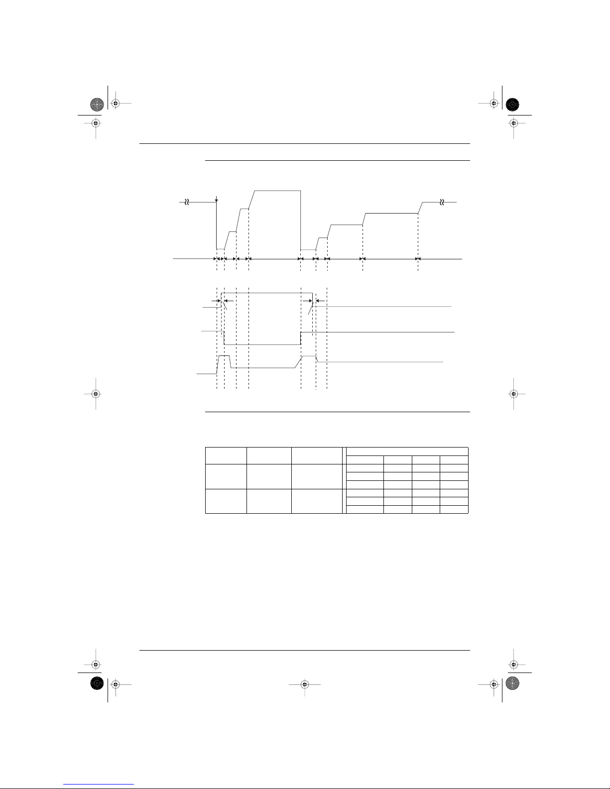
1.4 Defrost Control
Principle When frost deposit on the outdoor heat exchanger has increased in heating operation, change the
operation from heating cycle to cooling cycle for defrosting.
Start Conditions Defrost control is set by the following conditions:
During heating
More than 35 minutes after the compressor has started up
When condition 1 or 2 in the table below are applicable:
Conditions The following table shows the different conditions on which defrost control is based:
Condition Description
1
More than 35 minutes of accumulated running time
Less than 90 minutes of accumulated running time
Condition 1, 2 or 3 in the table below
2
More than 90 minutes of accumulated running time
Condition 1, 4 or 5 in the table below
Conditions Description
1 T
[outdoor heat exchanger]
< -12˚C for 1 min.
2
T
[ambient outdoor]
< 5˚C
T
[outdoor heat exchanger]
< (-5 + T
[ambient outdoor]
× 0.4)
check if T
[indoor heat exchanger]
decreases 5 times every 10 seconds
3
T
[ambient outdoor]
≥ 5˚C
T
[outdoor heat exchanger]
< -3˚C
check if T
[indoor heat exchanger]
decreases 5 times every 10 seconds
4
T
[ambient outdoor]
< 5˚C for 60 seconds
T
[outdoor heat exchanger]
< (-5 + T
[ambient outdoor]
× 0.4) for 60 seconds
5
T
[ambient outdoor]
≥ 5˚C for 60 seconds
T
[outdoor heat exchanger]
< -3˚C for 60 seconds
SiBE04-101.book Page 21 Monday, October 15, 2001 3:08 PM
General Functions SiBE04-101
22 Main Function
Time Chart
Stop Conditions
Defrost control is ended by the conditions as follows:
When the maximum time elapses.
T
[heat exchanger]
≥ (-1˚C × T
[ambient outdoor]
) + 18, or T
[heat exchanger]
≥ 20˚C.
Compressor
operation
frequency
4-way
valve
Cool
Warm
Fan
EVpulse
ON
OFF
Defrost
OFF
Defrost
ON
A Hz
B Hz
C Hz
76Hz
80Hz
90Hz
108Hz
35min.
3sec.
3sec.
450Pls
400Pls
450Pls
50sec.
60sec. 60sec.
280sec.
80sec.
60sec.
180sec. 300sec. 150min.
(R1016)
Minimum time
Maximum time
(including stop time)
Compressor frequency in defrosting
Class A B C
T [ambient
outdoor] ≥ 0˚C
2 min. approx. 9 min.
50 74 84 90
60 66 74 78
70 58 66 72
T [ambient
outdoor] < 0˚C
2 min. approx. 11 min.
50 78 88 94
60 70 78 82
70 62 70 76
SiBE04-101.book Page 22 Monday, October 15, 2001 3:08 PM
 Loading...