

Daikin FLX25HVEA, FTXD50JVEA9, FTXD60JVEA, CDX35HAVEA, FLX35HVEA Service Manual
...
Si18-201
J Series
[Applied Models]
!
!!
!Super Multi Plus : Cooling Only
!
!!
!Super Multi Plus : Heat Pump
Service
Manual

Si18-201
Table of Contents i
Super Multi Plus
Super Multi PlusSuper Multi Plus
Super Multi Plus
J Series
J SeriesJ Series
J Series
!
Heat Pump
Indoor Unit
FTX25JVEA9 FTXD50JVEA9 CDX25HAVEA FLX25HVEA FHYC35KVE9
FTX35JVEA9 FTXD60JVEA CDX35HAVEA FLX35HVEA FHYC50KVE9
FTX25JVEC FTXD71JVEA CDX50HAVEA FLX50JVEA9 FHYC60KVE9
FTX35JVEC FTX50HVEC CDX60HAVEA FLX60JVEA FHYC71KVE9
FTX25JAVET FTX60HVEC CDX25HAVEC FLX25HVEC FHYC35KV1C9
FTX35JAVET FTXD50JVET CDX35HAVEC FLX35HVEC FHYC50KV1C9
FTX25JAV1NB FTXD60JVET CDX50HAVEC FLX50HVEC FHYC60KV1C9
FTX35JAV1NB FTXD71JVET CDX60HAVEC FLX60HVEC FHYC71KV1C9
FTXD50JV1B CDX25HAV1NB FLX25HVET FDYM60FAV1
FTXD25KZV1B FTXD60JV1B CDX35HAV1NB FLX35HVET FDYM03FAV1
FTXD35KZV1B FTXD71JV1B CDX50HAV1NB FLX50HVET FDYM60FAV1C
FVX25KZV1B CDX60HAV1NB FLX60HVET FDYM03FAV1C
FVX35KZV1B CDX25JV1NB FLX25HV1NB FDYM60FAVAL
CDX35JV1NB FLX35HV1NB FDYM03FAVAL
CDX50JV1NB FLX 50JV1B
CDX60JV1NB FLX 60JV1B
CDX25JVEC
CDX35JVEC
Outdoor Unit
RMX140JVMC9 RMX140JVMT9 RMX140JVMB RMX140JZVMB
RMX140JVMC8
BP Unit
BPMK928B42 BPMK928B43
!
Cooling Only
Indoor Unit
FTK25JVE9 FTKD50JVE CDK25HAVE FLK25HVE FHYC35KVE9
FTK35JVE9 FTKD60JVE CDK35HAVE FLK35HVE FHYC50KVE9
FTK25JVEA9 FTKD71JVE CDK50HAVE FLK50HVE FHYC60KVE9
FTK35JVEA9 FTKD50JVEA9 CDK60HAVE FLK60HVE FHYC71KVE9
FTK25JVEC FTKD60JVEA CDK25HAVEA FLK25HVEA FHYC35KV1C9
FTK35JVEC FTKD71JVEA CDK35HAVEA FLK35HVEA FHYC50KV1C9
FTK25JAVET FTK50HVEC CDK50HAVEA FLK50JVEA9 FHYC60KV1C9
FTK35JAVET FTK60HVEC CDK60HAVEA FLK60JVEA FHYC71KV1C9
FTKD50JVET CDK25HAVEC FLK25HVEC FDY M60FAV1
FTKD60JVET CDK35HAVEC FLK35HVEC FDY M03FAV1
FTKD71JVET CDK50HAVEC FLK50HVEC FDY M60FAV1C
CDK60HAVEC FLK60HVEC FDYM03FAV1C
CDK25HAVET FLK25HVET FDYM60FAVAL
CDK35HAVET FLK35HVET FDYM03FAVAL
CDK50HAVET FLK50HVET
CDK60HAVET FLK60HVET
Outdoor Unit
RMK140JVMC9 RMK140JVMT9∗RMK140JAVM RMK140JZVMA
RMK140JVMC8
BP Unit
BPMK928B42 BPMK928B43
∗ The RMK140JAVM specifications are special. For details, see the next page.

Si18-201
ii Table of Contents
NOTICE : Special specifications
Model RMK140JAVM has the following different specifications from the others. Take the important notes below. This
model is designed for cooling mode only, which means it has no heating functions at all.
★★★★Important points : The model is not equipped with the receiver circuit.
1) The heating mode is not available because the following parts are not built in.
2) The following control features are not available.
3) Change the following values for this model.
4) The model is not provided with the surplus refrigerant control function.
PART 5 (5) EVL : Liquid pipe motorized valve Page
103~105
(6) EVG : Gas pipe motorized valve
(8) Capillary tube for gas purge
(9) Check valve
(10) Check valve
PART 5 3.8 Defrost Operation Page 122
3.12 Peak Cut Control Page 128
3.23 Warm-Up Function Page 141
3.27 Cooling Outdoor Unit SC Control Page 151
3.30 SH Control in Cooling Operation Page 157
3.31 SC Control in Heating Operation Page 159
3.32 Heat Exchanger Isothermal Control in Heating Operation Page 161
3.34 Inter-BP Units Heating Heat Exchanger Isothermal Control Page 163
3.37 4-Way Valve Operation Page 166
PART 5 3.11.1 20sec
→
10sec Page 126
PART 6 See "1.7 Cooling operation (multi-room operation - without surplus refrigerant control function) ". Page 178

Si18-201
Table of Contents iii
1. Introduction ............................................................................................ix
1.1 Safety Cautions.......................................................................................ix
Part 1 List of Function ..................................................................1
1. List of Function........................................................................................2
1.1 Function List for General........................................................ ..................2
1.2 Function List for China ............................................ .............................. ...3
1.3 Function List for Taiwan ........... ............... ............................... ............... ...4
1.4 Function List for Europe ....................................... ............................... .....5
1.5 Function List for Singapore, Malaysia, Indonesia..................... ................6
1.6 Function List for Australia.. ............................... ............................... ......... 7
1.7 Function List for Europe ....................................... ............................... .....8
Part 2 Specifications .................................................................... 9
1. Specifications........................................................................................10
1.1 Outdoor Units .........................................................................................10
1.2 BP Units ............... ............................ ................ ............................. ......... 1 8
1.3 Indoor Units (for General).......................................................................19
1.4 Indoor Units (for China)..........................................................................34
1.5 Indoor Units (for Taiwan)........................................................................43
1.6 Indoor Units (for Europe)........................................................................52
Part 3 Printed Circuit Board Connector Wiring Diagram
and Name ......................................................................... 59
1. Printed Circuit Board Connector Wiring Diagram and Name................60
1.1 Branch Provider Unit BPMK928B42, B43 ..............................................60
1.2 Outdoor Unit RMK (X) 140JVMT (C) 9 (8), RMK140JAVM,
RMX140JVMB, RMK (X) 140JZVMA (B) ...............................................61
1.3 FTK25 / 35J Series, FTX25 / 35J Series, FTXD25 / 35K Series,
FVX25 / 35K Series................................................................................64
1.4 FTK50~60HV Series, FTKD50~71JV Series, FTX50~60HV Series,
FTXD50~71JV Series.......... ................ ............................... ............... .....66
1.5 CDX25~60HAV Series, CDK25~60HAV Series....................... ..............68
1.6 FLK25~60HV Series, FLX25~60HV Series, FLK50 / 60JV Series,
FLX50 / 60JV Series ..............................................................................70
1.7 FHYC35~71KV Series............................................................................73
1.8 FDYM60FA, FDYM03FA Series.............................................................75
Part 4 Main Functions Indoor Unit..............................................77
1. Main Functions......................................................................................78
1.1 Main Functions in Split Type..................................................................78
1.2 SkyAir.....................................................................................................98
1.3 Cautions when SkyAir [Auto] [FAN] are used.......................................100

Si18-201
iv Table of Contents
Part 5 Main Functions Outdoor Unit / BP Unit..........................101
1. Refrigerant System and Function of Functional Parts
of Outdoor Unit....................................................................................103
1.1 Refrigerant System and Function of Functional Parts
of Outdoor Unit......................... ............... ................ ............... ..............103
1.2 Major Functional Parts .........................................................................104
1.3 Protective Devices, Thermistors, Sensors ...........................................106
2. Protection Device................................................................................107
2.1 Outdoor Unit.........................................................................................107
2.2 BP Unit............ ................ ............... ................ ............... ................ .......108
3. System control ....................................................................................109
3.1 Outline of System Control ....................................................................109
3.2 Mode Configuration...................... ............................... ......................... 110
3.3 Standby Control at Power ON..............................................................111
3.4 Cooling / Heating Standby Operation at Startup............................... ...112
3.5 Equalizing Control ...................... ............... ................ ...........................113
3.6 Determination of Initial Frequency........................................................115
3.7 Oil Return Operation ............................................................................120
3.8 Defrost Operation................................................. ................ ............... .122
3.9 Pre-Equalization Standby Operation....................................................123
3.10 Equalizi n g Contro l ............... ............................... ............................... ...124
3.11 Capacity Contr ol...................................... ............................... ..............126
3.12 Peak Cut Control..................................................................................128
3.13 Freeze-Up Prevention ..........................................................................129
3.14 Gas Shortage Malfunction....................................................................130
3.15 Discharge Pipe Control ... .............................................. .......................131
3.16 Input Current Control............................................................................132
3.17 Wet Protection Control I .......................................................................135
3.18 Electric Parts Cooling and Electric Parts /
Fin Temperature Control......................................... .............................136
3.19 Differential Pressure Control ................................................................137
3.20 Year-Round Cooling-Only Function .....................................................138
3.21 Nighttime Low Noise Control................................................................139
3.22 PI Control .............................................................................................140
3.23 Warm-Up Function...............................................................................141
3.24 Compressor Protection Control............................................................142
3.25 Fan Control...........................................................................................143
3.26 Motorized Valve Control of Outdoor Unit..............................................145
3.27 Cooling Outdoor Unit SC Control .........................................................151
3.28 BP Unit Motorized Valve Contr o l.......................... ................................152
3.29 Gas Pipe Isothermal Control in Cooling Operation ..............................155
3.30 SH Control in Cooling Operation..........................................................157
3.31 SC Control in Heating Operation..........................................................159
3.32 Heat Exchanger Isothermal Control in Heating Operation ...................161
3.33 BP Unit Motorized Valve Control in High Discharge
Pipe Temperature................................ ............... ............................... ...162
3.34 Inter-BP Units Heating Heat Exchanger Isothermal Control ................163
3.35 Inter-BP Units Gas Pipe Isothermal Control.........................................164
3.36 BP Unit Motorized Valve Control by Target Discharge
Pipe Temperature................................ ............... ............................... ...165
3.37 4-Way Valve Operation ........................................................................166

Si18-201
Table of Contents v
3.38 JIS Mode ..... ............... ................ ............... ................ ............... ............167
3.39 Pump Down Operation............................................................. ............168
3.40 Protection Control of SkyAir Indoor Units.............................................169
Part 6 Flow of Refrigerant ........................................................171
1. Flow of Refrigerant..............................................................................172
1.1 Flow of Refrigerant.................................... ............................... ............172
1.2 Standby Operation (Cooling)................................................................173
1.3 Equalizing Control (Cooling)................ .............................................. ...174
1.4 Oil Return Operation (Cooling).............................................................175
1.5 Low Outside Air Temperature Cooling .................................................176
1.6 All-Room Operation (Cooling) ..............................................................177
1.7 Multi-Room Operation (No Surplus Refrigerant) (Cooling)..... .............. 178
1.8 Multi-Room Operation (Cooling) (with Surplus Refrigerant)..... ............ 179
1.9 1-Room Operation — Indoor Unit with Large Capacity (Cooling) ........180
1.10 1-Room Operation — Indoor Unit with Small Capacity
(2.5 kW) (Cooling) ................................................................................181
1.11 Standby Operation (Heating)................................................................182
1.12 Equalizin g Contr o l (Heating) ............... .................................................183
1.13 Oil Return Operation (Heating).............................................................184
1.14 Defrost Operation ............... ............................................... ..................185
1.15 All-Room Operation (Heating)..............................................................186
1.16 Multi-Room Operation (with non-Operating Room Unit) (Heating).......187
1.17 Multi- Room Operation (Heating) ............. .............................................188
1.18 1-Room Operation — Indoor Unit with Large Capacity (Heating)........189
1.19 1-Room Operation — Indoor Unit with Small Capacity
(2.5 kW) (Heating)................................................................................190
Part 7 Operations ......................................................................191
1. Remote Controller...............................................................................192
1.1 Wireless Remote Controller ......... ............... ............................... ..........192
1.2 Wired Remote Controller.................................... ..................................202
Part 8 Operating Test ...............................................................205
1. Operating Test ....................................................................................206
1.1 Operating Test.................................. ............................... ................ .....206
1.2 Test Operation Switch...................... ............................... .....................209
1.3 Pump Down Operation Switch .............................................................210
1.4 Record of the Installation Position........................................................211
2. Method of Field Set.............................................................................212
2.1 Field Setting .........................................................................................212
2.2 Group Number Setting for Central Remote Control .............................220
2.3 Interface Adaptor for Room Airconditioner <KRP928A1S>............. .....221
2.4 Precautions: For RMK140J / RMX140J Outdoor Unit Users................223
Part 9 Service Diagnosis...........................................................225
1. Troubleshooting - Split Type Indoor Unit.............................................226
1.1 Troubleshooting with the Operation Lamp ...........................................226
1.2 Service Check Function ..................................... ................ ............... ...228

Si18-201
vi Table of Contents
1.3 Code Indication on the Remote Controller................ ................. ..........230
1.4 Troubleshooting....................................................................................231
1.5 Troubleshooting Detail .........................................................................232
2. Trou blesh ooting - SkyAir Indo or Unit.......... ................................. ..... ..246
2.1 The INSPECTION/TEST Button...........................................................246
2.2 Self-Diagnosis by Wired Remote Controller........................... ..............247
2.3 Fault Diagnosis by Wireless Remote Controller...................................248
2.4 Troubleshooting by LED on the Indoor Unit’s.......................................250
2.5 Troubleshooting by Remote Controller Display / LED Display.............251
2.6 Troubleshooting Detail .........................................................................252
3. Trou blesh oo ting - Out doo r Unit Related.............................................260
3.1 The Unit Runs but Doesn’t Cool (Heat) the Room............... ................260
3.2 7 Seg. Display on the Outdoor P. C. Board..........................................262
3.3 Troubleshooting Detail .........................................................................263
3.4 How to Check..................................................... ................ ............... ...300
4. BP Unit Trouble Diagnosis..................................................................310
4.1 PCB Parts Layout..... ................ ............... ................ ............... ..............310
4.2 LED On Branch Provider Unit (Diagnosis LEDs) .................................310
Part 10Removal Procedure ........................................................311
1. For BPMK928B42 · 43........................................................................312
1.1 Installation of Indoor Unit......................................................................312
1.2 Opening of Electrical Box Cover and Removal of PCB Mount.............313
1.3 Removal of Motorized Valve ......................................... .......................315
1.4 Removal of Thermistor.................................................. .......................318
2. Outdoor Unit........................................................................................320
2.1 Removal of Outer Panels..................................................................... 320
2.2 Removal of PCB and Electrical Box.....................................................321
2.3 Removal of Propeller Fans and Fan Motors.........................................329
2.4 Removal of Thermistor.................................................. .......................331
2.5 Removal of Motorized Valve ......................................... .......................332
2.6 Removal of Sound Insulation ................ .............................................. .334
2.7 Removal of Compressor................................................ .......................336
2.8 Removal of 4-way Valve.... .............................................. .....................338
3. Indoor Unit...........................................................................................342
3.1 Refer following table for indoor unit removal procedure.......................342
Part 11Cautions before Operation............................................. 343
1. Installation...........................................................................................344
1.1 Outdoor Unit.........................................................................................344
1.2 BP Unit............ ................ ............... ................ ............... ................ .......346
2. Wiring..................................................................................................348
2.1 Outdoor Unit.........................................................................................348
2.2 BP Unit............ ................ ............... ................ ............... ................ .......350
2.3 Outdoor Unit Rotary Switch Setting...................................................... 352
3. Others .................................................................................................354
3.1 Explanation for FTK(X)25/35J Series...... ................................. ............354
3.2 Explanation for FTK(X)50/60H and CDK(X)25~60H Series.................357

Si18-201
Table of Contents vii
Part 12Appendix......................................................................... 359
1. Pip ing Dia grams.......................................... ................................. ..... ..360
1.1 Outdoor Units .......................................................................................360
1.2 BP Units ............... ............... ................ ............... ................ ............... ...362
1.3 Indoor Units..........................................................................................363
2. Wiring Diagrams..................................................................................370
2.1 Outdoor Units .......................................................................................370
2.2 BP Units ............... ............... ................ ............... ................ ............... ...374
2.3 Indoor Units..........................................................................................375
Index .............................................................................................i
Drawings & Flow Charts ................................................................ v

Si18-201
viii Table of Contents
Si18-201 Introduction
ix
1. Introduction
1.1 Safety Cautions
Cautions and
Warnings
"
Be sure to read the following safety cautions before conducting repair work.
"
The caution items are classified into “ Warning” and “ Caution”. The “ Warning”
items are especially important since they can lead to death or serious injury if they are not
followed closely. The “ Caution” items can also lead to serious accidents under some
conditions if they are not followed. Therefore, be sure to observe all the safety caution items
described below.
"
About the pictograms
This symbol indicates an item for which caution must be exercised.
The pictogram shows the item to which attention must be paid.
This symbol indicates a prohibited action.
The prohibited item or action is shown inside or near the symbol.
This symbol indicates an action that must be taken, or an instruction.
The instruction is shown inside or near the symbol.
"
After the repair work is complete, be sure to conduct a test operation to ensure that the
equipment operates normally, and explain the cautions for operating the product to the
customer.
1.1.1 Cautions in Repair
Warning
Be sure to disconnect the power cable plug from the plug socket before
disassembling the equipment for a repair.
Working on the equipment that is connected to a power supply can cause an
electrical shook.
If it is necessary to supply power to the equipment to conduct the repair or
inspecting the circuits, do not touch any electrically charged sections of the
equipment.
If the refrigerant gas discharges during the repair work, do not touch the
discharging refrigerant gas.
The refrigerant gas can cause frostbite.
When disconnecting the suction or discharge pipe of the compressor at the
welded section, release the refrigerant gas completely at a well-ventilated
place first.
If there is a gas remaining inside the compressor, the refrigerant gas or
refrigerating machin e oil d ischa rges whe n the pi pe is di scon nected , and it can
cause injury.
If the refrigerant gas leaks during the repair work, ventilate the area. The
refrigerant gas can generate toxic gases when it contacts flames.
The step-up capacitor supplies high-voltage electricity to the electrical
components of the outdoor unit.
Be sure to discharge the capacitor completely before conducting repair work.
A charged capacitor can cause an electrical shock.
Do not start or stop the air con ditioner op eration by p lugging or unpl ugging the
power cable plug.
Plugging or unplugging the power cable plug to operate the equipment can
cause an electrical shock or fire.
Introduction Si18-201
x
1.1.2 Cautions Regarding Products after Repair
Caution
Do not repair the electrical components with wet hands.
Working on the equipment with wet hands can cause an electrical shock.
Do not clean the air conditioner by splashing wa ter.
Washing the unit with water can cause an electrical shock.
Be sure to provide the grounding when repairing the equipment in a humid or
wet place, to avoid electrical shoc ks.
Be sure to turn off the power switc h and unpl ug the power c able when c leaning
the equipment.
The internal fan rotates at a high speed, and cause injury.
Do not tilt the unit when removing it.
The water inside the unit can spill and wet the furniture and floor.
Be sure to check that the refrigerating cycle section has cooled down
sufficiently before conducting repair work.
Working on the unit when the re frigerating cycle sectio n is hot can cause burns .
Use the welder in a well-ventilated place.
Using the welder in an enclosed room can cause oxygen deficiency.
Warning
Be sure to use parts liste d in the se rvi ce p arts li st of the applicable mo del and
appropriate tools to conduct repair work. Never attempt to modify the
equipment.
The use of inappropriate parts or tools can cause an electrical shock,
excessive heat generation or fire.
When relocating the equipment, make sure that the new installation site has
sufficient strength to withstand the weight of the equipment.
If the installation site does not have sufficient strength and if the installation
work is not conducted securely, the equipment can fall and cause injury.
Be sure to install the product correctly by using the provided standard
installat ion frame.
Incorrect use of the installation frame and improper installation can cause the
equipment to fall, resulting in injury.
For integral units
only
Be sure to install the product securely in the installation frame mounted on a
window frame.
If the unit is not securely mounted, it can fall and cause injury.
For integral units
only
Be sure to use an exclusive power circuit for the equipment, and follow the
technical standards related to the electrical equipment, the internal wiring
regulations and the instruction manual for installation when conducting
electrical work.
Insufficient power circuit capacity and improper electrical work can cause an
electrical shock or fire.
Si18-201 Introduction
xi
1.1.3 Inspection after Repair
Be sure to use the s pe ci fie d c ab le to connect between the indoor and o utd oor
units. Make the co nnections secure ly and route the cable properly s o that there
is no force pulling the cable at the connection terminals.
Improper connections can cause excessive heat generation or fire.
When connecting the cable between the indoor and outdoor units, make sure
that the terminal cover does not lift off or dismount because of the cable.
If the cover is not mounted prop erly, the terminal conn ection section ca n cause
an electrical shock, excessive heat generation or fire.
Do not damage or modify the power cable.
Damaged or modified power cable can cause an electrical shock or fire.
Placing heavy items on the po wer cable, and heating or pulli ng the power cable
can damage the cable.
Do not mix air or gas other than the specified refrigerant (R22) in the refrigerant
system.
If air enters the refrigerating system, an excessively high pressure results,
causing equipment damage and injury.
If the refrigerant gas leaks, be sure to locate the leak and repair it before
charging the refrigerant. After charging refrigerant, make sure that there is no
refrigerant leak.
If the leak cannot be located and the repair work must be stopped, be sure to
perform pump-down and clos e the service valve , to prevent the refrig erant gas
from leaking into the room. The refrigerant gas itself is harmless, but it can
generate toxic gases when it contacts flames, such as fan and other heaters,
stoves and ranges.
When replacing the coin battery in the remote controller, be sure to disposed
of the old battery to prevent children from swallowing it.
If a child swallows the coin battery, see a doctor immediately.
Warning
Caution
Installation of a leakage breaker is ne cessary in so me cases dep ending on the
conditions of the installation site, to prevent electrical shocks.
Do not install the equipment in a place where there is a possibility of
combustible gas leaks.
If a combustible gas leaks and remains around the unit, it can cause a fire.
Be sure to install the packing and seal on the installation frame properly.
If the packing and sea l are not inst alled properly , water can ent er the room and
wet the furniture and floor.
For integral units
only
Warning
Check to make sure that t he p ower c ab le p lug is not dirty or l oo se, then insert
the plug into a power outlet all the way.
If the plug has dust or loose conne ction, it can cause an electri cal shoc k or fire.
If the power cable and lead wires have scratches or deteriorated, be sure to
replace them.
Damaged cable and wires can cause an electrical shock, excessive heat
generation or fire.
Do not use a joined power cable or extension cable, or share the same power
outlet with other electrical appliances, since it can cause an electrical shock,
excessive heat generation or fire.

Introduction Si18-201
xii
1.1.4 Using Icons
Icons are used to attract the attention of the reader to specific information. The meaning of each
icon is described in the table below:
1.1.5 Using Icons List
Caution
Check to see if the parts a nd wires are mounted and c onn ec ted prope rly , an d
if the connections at the soldered or crimped terminals are secure.
Improper installation and connections can cause excessive heat generation,
fire or an electrical shock.
If the installation platform or frame has corroded, replace it.
Corroded installation platform or frame can cause the unit to fall, resulting in
injury.
Check the grounding, and repair it if the equipment is not properly grounded.
Improper grounding can cause an electrical shock.
Be sure to measure the insulation resistance after the repair, and make sure
that the resistance is 1 MΩ or higher.
Faulty insulation can cause an electrical shock.
Be sure to check the drainage of the indoor unit after the repair.
Faulty drainage can cause the water to enter the room and wet the furniture
and floor.
Icon Type of
Information
Description
Note:
Note A “note” provides i nform at ion that is not indi sp ens ab le, but may
nevertheless be valuable to the reader, such as tips and tricks.
Caution
Caution A “cautio n” is used when there is danger tha t the reader, through
incorrect manipulatio n, may dama ge equipmen t, loose data , get
an unexpected result or has to restart (part of) a procedure.
Warning
Warning A “warning” is used when there is danger of personal injury.
Reference A “reference” guides the reader to other places in this binder or
in this manual, where he/she will find additional information on a
specific topic.

Si18-201
List of Function 1
Part 1
Part 1Part 1
Part 1
List of Function
List of FunctionList of Function
List of Function
1. List of Function........................................................................................2
1.1 Function List for General........................................................ ..................2
1.2 Function List for China ............................................ .............................. ...3
1.3 Function List for Taiwan ........... ............... ............................... ............... ...4
1.4 Function List for Europe ....................................... ............................... .....5
1.5 Function List for Singapore, Malaysia, Indonesia..................... ................6
1.6 Function List for Australia.. ............................... ............................... ......... 7
1.7 Function List for Europe ....................................... ............................... .....8
The RMK 140JA VM s pecifications are sp ecial. Refer to <R MK14 0JAVM 's
important points> (on page ii) for the changes in contents.

List of Function Si18-201
2 List of Function
1. List of Function
1.1 Function List for General
★1
! : for FLK, FLX50/60J
★2
–
: for FLK, FLX50/60J
Division
Indoor
Unit /
Outdoor
Unit
Inverter (with Inverter Power Control)
PAM control (Pulse Amplitude Modulation Control)
Horizontal Scroll, Oval Scroll Compressor (DAIKIN SCROLL)
Reluctance DC Motor
Dual Flaps
Power-Airflow Dual Flaps
Power-Airflow Diffuser
Wide-Angle Louvers
Vertical Auto-Swing (Up and Down)
Horizontal Auto-Swing (Right and Left)
3-D Airflow
Auto Fan Speed
Silent Operation Control (Automatic)
Intelligent Eye
Automatic Oper at ion
Programme Dry Function
Fan Only
Inverter Powerful Operation
Home Leave Operation
Indoor Unit On/Off Switch
Air-Purifying Filter
with Bacteriostatic, Virustatic & Deodorizing Functions
Mold-Proof Air Filter
Washable Grille
Filter Cleaning Indicator
Good-Sleep Cooling Operation
72-Hour On/Off Timer
24-Hour On/Off Timer
Night Set Mode
Auto-Restart ( a fter Power Failure)
Self-Diagnosis Digital Display
Self-Diagnosis LED Display
Wiring-Error Check
Anticorrosion Treatment of Outdoor Heat Exchanger
Multi-Split/Split Type Compatible Indoor Unit
High-Ceiling Application
Chargeless
Wireless (FHYC, FDYM: O p tion)
Wired (FHYC, FDYM: Option)
Group Control by 1 Remote Controller
Cooling Only
Outdoor Unit
RMK
140J
!!!!
––––––––!––––!–– – ––––––––!!–!––
115
m
–––
Indoor Unit
Wall
Mounted
Type
FTK25/
35J
!
–––!!–
!!––!–!–!!!–!!!!–!–!!!!
–––!––!––
FTKD
50/60/
71J
!
–––
!!!!!!!!
–––
!!!!! ! !!
–––
!!!!!––!
––!––
Floor/
Ceiling
Suspended
Dual Type
FLK25/
35/50/
60H
50/60J
!
––––––!!––!–––
!!!★1!!!
–
!
★2
––
!!!!!
––★1––!––
Ceiling
Mounted
Cassette
Type
FHYC
35/50/
60/71K
––––––––
!
––!–––!!––– –!–!–!––
!!!––!!–!!!
Duct
Connected
Type
CDK25/
35/50/
60HA
!
––––––––––!–––
!!!–!
– –––––
!!!!!
–––––!––
FDYM
60/03FA
–––––––––––––––
!!
––––––!–!––
!!!––!
––
!!!
Heat Pump
Outdoor Unit
RMX
140J
!!!!
––––––––!––––––– – ––––––––!!–!––
115
m
–––
Indoor Unit
Wall
Mounted
Type
FTX25/
35J
!
–––!!–
!!––!–!!!–!–!!!!–!–!!!!
–––!––!––
FTXD
50/60/
71J
!
–––
!!!!!!!!––!!–!!!!!!
–––
!!!!!––!
––!––
Floor/
Ceiling
Suspended
Dual Type
FLX25/
35H
50/60J
!
––––––!!––!––!!–
!★1!!!
–
!
★2
––
!!!!!
––★1––!––
Ceiling
Mounted
Cassette
Type
FHYC
35/50/
60/71K
––––––––
!
––!––
!!!
––– –!–!–!––
!!!––!!–!!!
Duct
Connected
Type
CDX25/
35/50/
60HA
!
––––––––––!––!!–!–!– –––––
!!!!!
–––––!––
FDYM
60/03FA
––––––––––––––
!!!
––––––!–!––
!!!––!
––
!!!
Si18-201 List of Function
List of Function 3
1.2 Function List for China
Division
Indoor
Unit /
Outdoor
Unit
Inverter (with Inverter Power Control)
PAM control (Pulse Amplitude Modulation Control)
Horizontal Scroll, Oval Scroll Compressor (DAIKIN SCROLL)
Reluctance DC Motor
Dual Flaps
Power-Airflow Dual Flaps
Power-Airflow Diffuser
Wide-Angle Louvers
Vertical Auto-Swing (Up and Down)
Horizontal Auto-Swing (Right and Left)
Auto Fan Speed
Silent Operation Control (Automatic)
Intelligent Eye
Automatic Operation
Programme Dry Function
Fan Only
Inverter Powerful Operation
Indoor Unit On/Off Switch
Air-Purifying Filter
with Bacteriostatic, Virustatic & Deodorizing Functions
Mold-Proof Air Filter
Washable Grille
Filter Cleaning Indicator
Good-Sleep Cooling Operation
72-Hour On/Off Timer
24-Hour On/Off Timer
Night Set Mode
Auto-Restart (after Power Failure)
Self-Diagnosis Digital Display
Self-Diagnosis LED Display
Wiring-Error Check
Anticorrosion Treatment of Outdoor Heat Exchanger
Multi-Split/Split Type Compatible Indoor Unit
High-Ceiling Application
Chargeless
Wireless (FHYC, FDYM: Option)
Wired (FHYC, FDYM: Option)
Group Control by 1 Remote Controller
Cooling Only
Outdoor Unit
RMK
140J
!!!!
–––––––!––––!– – ––––––––!!–!––
115
m
–––
Indoor Unit
Wall
Mounted
Type
FTK25/
35J
!
–––!!–
!!–!–!–!!!!!!!–!–!!!!
–––!––!––
FTK
50/60H
!
––––––
!!!!
–––
!!!! ! !!!––!!!!!
–––––!––
Floor/
Ceiling
Suspended
Dual Type
FLK25/
35/50/
60H
!
––––––!!–!–––
!!!!!!–!
––
!!!!!
–––––!––
Ceiling
Mounted
Cassette
Type
FHYC
35/50/
60/71K
––––––––
!–!
–––!!–– –!–!–!––
!!!––!!–!!!
Duct
Connected
Type
CDK25/
35/50/
60HA
!
–––––––––!–––
!!!!
– –––––
!!!!!
–––––!––
FDYM
60/03FA
––––––––––––––
!!
–––––!–!––
!!!––!
––
!!!
Heat Pump
Outdoor Unit
RMX
140J
!!!!
–––––––!–––––– – ––––––––!!–!––
115
m
–––
Indoor Unit
Wall
Mounted
Type
FTX25/
35J
!
–––!!–
!!–!–!!!–!!!!!–!–!!!!
–––!––!––
FTX
50/60H
!
––––––
!!!!––!!–!!!!!!––!!!!!
–––––!––
Floor/
Ceiling
Suspended
Dual Type
FLX25/
35/50/
60H
!
––––––!!–!––!!–
!!!!–!
––
!!!!!
–––––!––
Ceiling
Mounted
Cassette
Type
FHYC
35/50/
60/71K
––––––––
!–!
––
!!!
–– –!–!–!––
!!!––!!–!!!
Duct
Connected
Type
CDX25/
35/50/
60HA (J)
!
–––––––––!––!!–
!!
– –––––
!!!!!
–––––!––
FDYM
60/03FA
–––––––––––––
!!!
–––––!–!––
!!!––!
––
!!!
List of Function Si18-201
4 List of Function
1.3 Function List for Taiwan
Division
Indoor
Unit /
Outdoor
Unit
Inverter (with Inverter Power Control)
PAM control (Pulse Amplitude Modulation Control)
Horizontal Scroll, Oval Scroll Compressor (DAIKIN SCROLL)
Reluctance DC Motor
Dual Flaps
Power-Airflow Dual Flaps
Power-Airflow Diffuser
Wide-Angle Louvers
Vertical Auto-Swing (Up and Down)
Horizontal Auto-Swing (Right and Left)
3-D Airflow
Auto Fan Speed
Silent Operation Control (Automatic)
Intelligent Eye
Automatic Operation
Programme Dry Function
Fan Only
Inverter Powerful Operation
Home Leave Operation
Indoor Unit On/Off Switch
Air-Purifying Filter
with Bacteriostatic, Virustatic & Deodorizing Functions
Mold-Proof Air Filter
Washable Grille
Filter Cleaning Indicator
Good-Sleep Cooling Operation
72-Hour On/Off Timer
24-Hour On/Off Timer
Night Set Mode
Auto-Restart (after Power Failure)
Self-Diagnosis Digital Display
Self-Diagnosis LED Display
Wiring-Error Check
Anticorrosion Treatment of Outdoor Heat Exchanger
Multi-Split/Split Type Compatible Indoor Unit
High-Ceiling Application
Chargeless
Wireless (FHYC), FDYM: Opti on )
Wired (FHYC, FDYM: Option)
Group Control by 1 Remote Controller
Cooling Only
Outdoor Unit
RMK
140J
!!!!
––––––––!––––!–– – ––––––––!!–!––
115
m
–––
Indoor Unit
Wall
Mounted
Type
FTK25/
35J
!
–––!!–
!!––!–!–!!!–!!!!–!–!!!!
–––!––!––
FTKD
50/60/
71J
!
–––
!!!!!!!!
–––
!!!!! ! !!
–––
!!!!!––!
––!––
Floor/
Ceiling
Suspended
Dual Type
FLK25/
35/50/
60H
!
––––––!!––!–––
!!!–!!!–!
––
!!!!!
––★1––!––
Ceiling
Mounted
Cassette
Type
FHYC
35/50/
60/71K
––––––––
!
––!–––!!––– –!–!–!––
!!!––!!–!!!
Duct
Connected
Type
FDYM
60/03FA
–––––––––––
!
–––!!––––––!–!––
!!!––!
––
!!!
Heat Pump
Outdoor Unit
RMX
140J
!!!!
––––––––!––––––– – ––––––––!!–!––
115
m
–––
Indoor Unit
Wall
Mounted
Type
FTX25/
35J
!
–––!!–
!!––!–!!!–!–!!!!–!–!!!!
–––!––!––
FTXD
50/60/
71J
!
–––
!!!!!!!!––!!–!!!!!!
–––
!!!!!––!
––!––
Floor/
Ceiling
Suspended
Dual Type
FLX25/
35/
50/60H
!
––––––!!––!––!!–!–
!!!–!
––
!!!!!
––★1––!––
Ceiling
Mounted
Cassette
Type
FHYC
35/50/
60/71K
––––––––
!
––!––
!!!
––– –!–!–!––
!!!––!!–!!!
Duct
Connected
Type
FDYM
60/03FA
–––––––––––
!
––
!!!–!
––––!–!––
!!!––!
––
!!!
Si18-201 List of Function
List of Function 5
1.4 Function List for Europe
★1
! : for FLX50/60J
★2
–
: for FLX50/60J
Division
Indoor
Unit /
Outdoor
Unit
Inverter (with Inverter Power Control)
PAM control (Pulse Amplitude Modulation Control)
Horizontal Scroll, Oval Scroll Compressor (DAIKIN SCROLL)
Reluctance DC Motor
Dual Flaps
Power-Airflow Dual Flaps
Power-Airflow Diffuser
Wide-Angle Louvers
Vertical Auto-Swing (Up and Down)
Horizontal Auto-Swing (Right and Left)
3-D Airflow
Auto Fan Speed
Silent Operation Control (Automatic)
Intelligent Eye
Automatic Operation
Programme Dry Function
Fan Only
Inverter Powerful Operation
Home Leave Operation
Indoor Unit On/Off Switch
Air-Purifying Filter
with Bacteriostatic, Virustatic & Deodorizing Functions
Mold-Proof Air Filter
Washable Grille
Filter Cleaning Indicator
Good-Sleep Cooling Operation
72-Hour On/Off Timer
24-Hour On/Off Timer
Night Set Mode
Auto-Restart (after Power Failure)
Self-Diagnosis Digital Display
Self-Diagnosis LED Display
Wiring-Error Check
Anticorrosion Treatment of Outdoor Heat Exchanger
Multi-Split/Split Type Compatible Indoor Unit
High-Ceiling Application
Chargeless
Wireless (FHYC: Option)
Wired (FHYC, FDYM: Option)
Group Control by 1 Remote Controller
Heat Pump
Outdoor Unit
RMX
140J
!!!!
––––––––!––––––– – ––––––––!!–!––
115
m
–––
Indoor Unit
Wall
Mounted
Type
FTX25/
35JA
!
–––!!–
!!––!–!!!–!–!!!!–!–!!!!
–––!––!––
FTXD
25/35KZ
!
––––!–
!!––!–!!!–!!!!!!
–––
!!!!!––!
––!––
FTXD
50/60/
71J
!
–––
!!!!!!!!––!!–!!!!!!
–––
!!!!!––!
––!––
Floor/
Ceiling
Suspended
Dual Type
FLX25/
35H
FLX50/
60J
!
––––––!!––!––!!–
!★1!!!
–
!
★2
––
!!!!!
––★1––!––
Floor
Standing
Type
FVX25/
35KZ
!
––––––!!––!––!!–
!!!!!!
–––
!!!!!––!
––!––
Ceiling
Mounted
Cassette
Type
FHYC
35/50/
60/71
B7
––––––––
!
––!––
!!!
––– –!–!–!––
!!!––!!–!!!
Duct
Connected
Type
CDX
25/35/
50/60
HA (J)
!
––––––––––!––!!–!–!– –––––
!!!!!
–––––!––
FHYB
35/45/
60/71
FK7
––––––––––––––
!!!
––––––!–!––
!!!––!
–––
!!
List of Function Si18-201
6 List of Function
1.5 Function List for Singapore, Malaysia, Indonesia
Division
Indoor
Unit /
Outdoor
Unit
Inverter (with Inverter Power Control)
PAM control (Pulse Amplitude Modulation Control)
Horizontal Scroll, Oval Scroll Compressor (DAIKIN SCROLL)
Reluctance DC Motor
Dual Flaps
Power-Airflow Dual Flaps
Power-Airflow Diffuser
Wide-Angle Louvers
Vertical Auto-Swing (Up and Down)
Horizontal Auto-Swing (Right and Left)
3-D Airflow
Auto Fan Speed
Silent Operation Control (Automatic)
Intelligent Eye
Automatic Operation
Programme Dry Function
Fan Only
Inverter Powerful Operation
Home Leave Operation
Indoor Unit On/Off Switch
Air-Purifying Filter
with Bacteriostatic, Virustatic & Deodorizing Functions
Mold-Proof Air Filter
Washable Grille
Filter Cleaning Indicator
Good-Sleep Cooling Operation
72-Hour On/Off Timer
24-Hour On/Off Timer
Night Set Mode
Auto-Restart (after Power Failure)
Self-Diagnosis Digital Display
Self-Diagnosis LED Display
Wiring-Error Check
Anticorrosion Treatment of Outdoor Heat Exchanger
Multi-Split/Split Type Compatible Indoor Unit
High-Ceiling Application
Chargeless
Wireless (FHYC, FDYM: Option)
Wired (FHYC, FDYM: Option)
Group Control by 1 Remote Controller
Cooling Only
Outdoor Unit
RMK
140JA
!!!!
––––––––!––––!–– – ––––––––!!–!––––––
Indoor Unit
Wall
Mounted
Type
FTK25/
35J
!
–––!!–
!!––!–!–!!!–!!!!–!–!!!!
–––!––!––
FTKD
50/60/
71J
!
–––
!!!!!!!!
–––
!!!!! ! !!
–––
!!!!!––!
––!––
Floor/
Ceiling
Suspended
Dual Type
FLK25/
35/50/
60H
!
––––––!!––!–––
!!!–!!!–!
––
!!!!!
––★1––!––
Ceiling
Mounted
Cassette
Type
FHYC
35/50/
60/71K
––––––––
!
––!–––!!––– –!–!–!––
!!!––!!–!!!
Duct
Connected
Type
CDK25/
35/50/
60HA
!
––––––––––!–––
!!!–!
– –––––
!!!!!
–––––!––
FDYM
60/03FA
–––––––––––––––
!!
––––––!–!––
!!!––!
––
!!!
Si18-201 List of Function
List of Function 7
1.6 Function List for Australia
★1
! : for FLK, FLX50/60J
★2
–
: for FLK, FLX50/60J
Division
Indoor
Unit /
Outdoor
Unit
Inverter (with Inverter Power Control)
PAM control (Pulse Amplitude Modulation Control)
Horizontal Scroll, Oval Scroll Compressor (DAIKIN SCROLL)
Reluctance DC Motor
Dual Flaps
Power-Airflow Dual Flaps
Power-Airflow Diffuser
Wide-Angle Louvers
Vertical Auto-Swing (Up and Down)
Horizontal Auto-Swing (Right and Left)
3-D Airflow
Auto Fan Speed
Silent Operation Control (Automatic)
Intelligent Eye
Automatic Operation
Programme Dry Function
Fan Only
Inverter Powerful Operation
Home Leave Operation
Indoor Unit On/Off Switch
Air-Purifying Filter
with Bacteriostatic, Virustatic & Deodorizing Functions
Mold-Proof Air Filter
Washable Grille
Filter Cleaning Indicator
Good-Sleep Cooling Operation
72-Hour On/Off Timer
24-Hour On/Off Timer
Night Set Mode
Auto-Restart (after Power Failure)
Self-Diagnosis Digital Display
Self-Diagnosis LED Display
Wiring-Error Check
Anticorrosion Treatment of Outdoor Heat Exchanger
Multi-Split/Split Type Compatible Indoor Unit
High-Ceiling Application
Chargeless
Wireless (FHYC, FDYM: Option)
Wired (FHYC, FDYM: Option)
Group Control by 1 Remote Controller
Cooling Only
Outdoor Unit
RMK
140J
!!!!
––––––––!––––!–– – ––––––––!!–!––
115
m
–––
Indoor Unit
Wall
Mounted
Type
FTK25/
35J
!
–––!!–
!!––!–!–!!!–!!!!–!–!!!!
–––!––!––
FTKD
50/60/
71J
!
–––
!!!!!!!!
–––
!!!!! ! !!
–––
!!!!!––!
––!––
Floor/
Ceiling
Suspended
Dual Type
FLK25/
35H
50/60J
!
––––––!!––!–––
!!!★1!!!
–
!
★2
––
!!!!!
––★1––!––
Ceiling
Mounted
Cassette
Type
FHYC
35/50/
60/71K
––––––––
!
––!–––!!––– –!–!–!––
!!!––!!–!!!
Duct
Connected
Type
CDK25/
35/50/
60HA
!
––––––––––!–––
!!!–!
– –––––
!!!!!
–––––!––
FDYM
60/03FA
–––––––––––––––
!!
––––––!–!––
!!!––!
––
!!!
Heat Pump
Outdoor Unit
RMX
140J
!!!!
––––––––!––––––– – ––––––––!!–!––
115
m
–––
Indoor Unit
Wall
Mounted
Type
FTX25/
35J
!
–––!!–
!!––!–!!!–!–!!!!–!–!!!!
–––!––!––
FTXD
50/60/
71J
!
–––
!!!!!!!!––!!–!!!!!!
–––
!!!!!––!
––!––
Floor/
Ceiling
Suspended
Dual Type
FLX25/
35H
50/60J
!
––––––!!––!––!!–
!★1!!!
–
!
★2
––
!!!!!
––★1––!––
Ceiling
Mounted
Cassette
Type
FHYC
35/50/
60/71K
––––––––
!
––!––
!!!
––– –!–!–!––
!!!––!!–!!!
Duct
Connected
Type
CDX25/
35/50/
60HA
!
––––––––––!––!!–!–!– –––––
!!!!!
–––––!––
FDYM
60/03FA
––––––––––––––
!!!
––––––!–!––
!!!––!
––
!!!
List of Function Si18-201
8 List of Function
1.7 Function List for Europe
★1
! : for FLX50/60J
★2
–
: for FLX50/60J
Division
Indoor
Unit /
Outdoor
Unit
Inverter (with Inverter Power Control)
PAM control (Pulse Amplitude Modulation Control)
Horizontal Scroll, Oval Scroll Compressor (DAIKIN SCROLL)
Reluctance DC Motor
Dual Flaps
Power-Airflow Dual Flaps
Power-Airflow Diffuser
Wide-Angle Louvers
Vertical Auto-Swing (Up and Down)
Horizontal Auto-Swing (Right and Left)
3-D Airflow
Auto Fan Speed
Silent Operation Control (Automatic)
Intelligent Eye
Automatic Operation
Programme Dry Function
Fan Only
Inverter Powerful Operation
Home Leave Operation
Indoor Unit On/Off Switch
Air-Purifying Filter
with Bacteriostatic, Virustatic & Deodorizing Functions
Mold-Proof Air Filter
Washable Grille
Filter Cleaning Indicator
Good-Sleep Cooling Operation
72-Hour On/Off Timer
24-Hour On/Off Timer
Night Set Mode
Auto-Restart (after Power Failure)
Self-Diagnosis Digital Display
Self-Diagnosis LED Display
Wiring-Error Check
Anticorrosion Treatment of Outdoor Heat Exchanger
Multi-Split/Split Type Compatible Indoor Unit
High-Ceiling Application
Chargeless
Wireless (FHYC: Option)
Wired (FHYC, FDYM: Option)
Group Control by 1 Remote Controller
Heat Pump
Outdoor Unit
RMX
140JZ
!!!!
––––––––!––––––– – ––––––––!!–!––
115
m
–––
Indoor Unit
Wall
Mounted
Type
FTX25/
35JA
!
–––!!–
!!––!–!!!–!–!!!!–!–!!!!
–––!––!––
FTXD
25/35KZ
!
––––!–
!!––!–!!!–!!!!!!
–––
!!!!!––!
––!––
FTXD
50/60/
71J
!
–––
!!!!!!!!––!!–!!!!!!
–––
!!!!!––!
––!––
Floor/
Ceiling
Suspended
Dual Type
FLX25/
35H
FLX50/
60J
!
––––––!!––!––!!–
!★1!!!
–
!
★2
––
!!!!!
––★1––!––
Floor
Standing
Type
FVX25/
35KZ
!
––––––!!––!––!!–
!!!!!!
–––
!!!!!––!
––!––
Ceiling
Mounted
Cassette
Type
FHYC
35/50/
60/71
B7
––––––––
!
––!––
!!!
––– –!–!–!––
!!!––!!–!!!
Duct
Connected
Type
CDX
25/35/
50/60
HA
!
––––––––––!––!!–!–!– –––––
!!!!!
–––––!––
FHYB
35/45/
60/71
FK7
––––––––––––––
!!!
––––––!–!––
!!!––!
–––
!!

Si18-201
Specifications 9
Part 2
Part 2Part 2
Part 2
Specifications
SpecificationsSpecifications
Specifications
1. Specifications........................................................................................10
1.1 Outdoor Units .........................................................................................10
1.2 BP Units ............... ............................ ................ ............................. ......... 1 8
1.3 Indoor Units (for General).......................................................................19
1.4 Indoor Units (for China)..........................................................................34
1.5 Indoor Units (for Taiwan)........................................................................43
1.6 Indoor Units (for Europe)........................................................................52
The RMK 140JA VM s pecifications are sp ecial. Refer to <R MK14 0JAVM 's
important points> (on page ii) for the changes in contents.
Specifications Si18-201
10 Specifications
1. Specifications
1.1 Outdo or Un its
1.1.1 Cooling Only
Notes:
1.
★
Refer to Engineering Data Book.
2. The data are based on the conditions shown in the table below.
50Hz 220-240V / 60Hz 220-230V
Model RMK140JVMC9 (8)
Cooling Capacity (19.0°CWB)
kW 14.5
kcal/h 12,470
Power Consumption
★
W 5,000
Running Current
★
A 23.2
Casing Color Ivory W h ite
Compressor
Type Hermetically Sealed Scroll Type (Oval Discharge)
Model JT100FBVD
Motor Output W 3,300
Refrigerant
Oil
Model SUNISO 4GSD.I.
Charge kg 1.5
Refrigerant
Type R22
Charge kg 9.9
Air Flow Rate
m³/min
H 114
L 104
cfm
H 4,024
L 3,671
Fan
Type Propeller
Motor Output W (Upper Side) H : 53 L : 38 (Lower Side) H : 41 L : 30
Running Current A (Upper Side) H : 0.50 L : 0.45 (Lower Side) H : 0.47 L : 0.42
Power Consumption W (Upper Side) H : 93.1 L : 78.8 (Lower Side) H : 81.3 L : 68.8
Power Factor % 100
Starting Current A 29.0
Dimensions (H×W×D) mm 1,345×880×320
Package Dimensions mm 918×394×1,397
Weight kg 134
Gross Weight kg 143
Operation Sound dBA 53
Piping
Connection
Liquid mm
φ
9.5 (Flare Connection)
Gas mm
φ
19.1 (Flare Connection)
Drain mm
φ
18
Heat Insulation Both Liquid and Gas Pipes
No. of Wiring Connection 3 for Power Supply, 4 for Interunit Wiring (Including Earth Wiring)
Max. Interunit Piping Length m
115 (Total Main Piping and Branch Piping)
55 (Total Main Piping), 60 (Total Branch Piping)
15 (Max. Length for Each Room)
Amount of Additional Charge g/m Chargeless
Max. Installation Height Difference m 30 (Between Indoor or BP Unit and Outdoor Unit), 15 (Between Indoor or BP Units)
Drawing No. 3D030948A
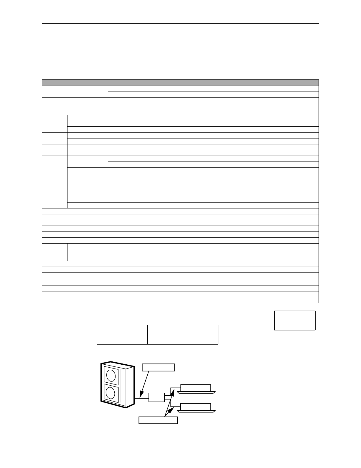
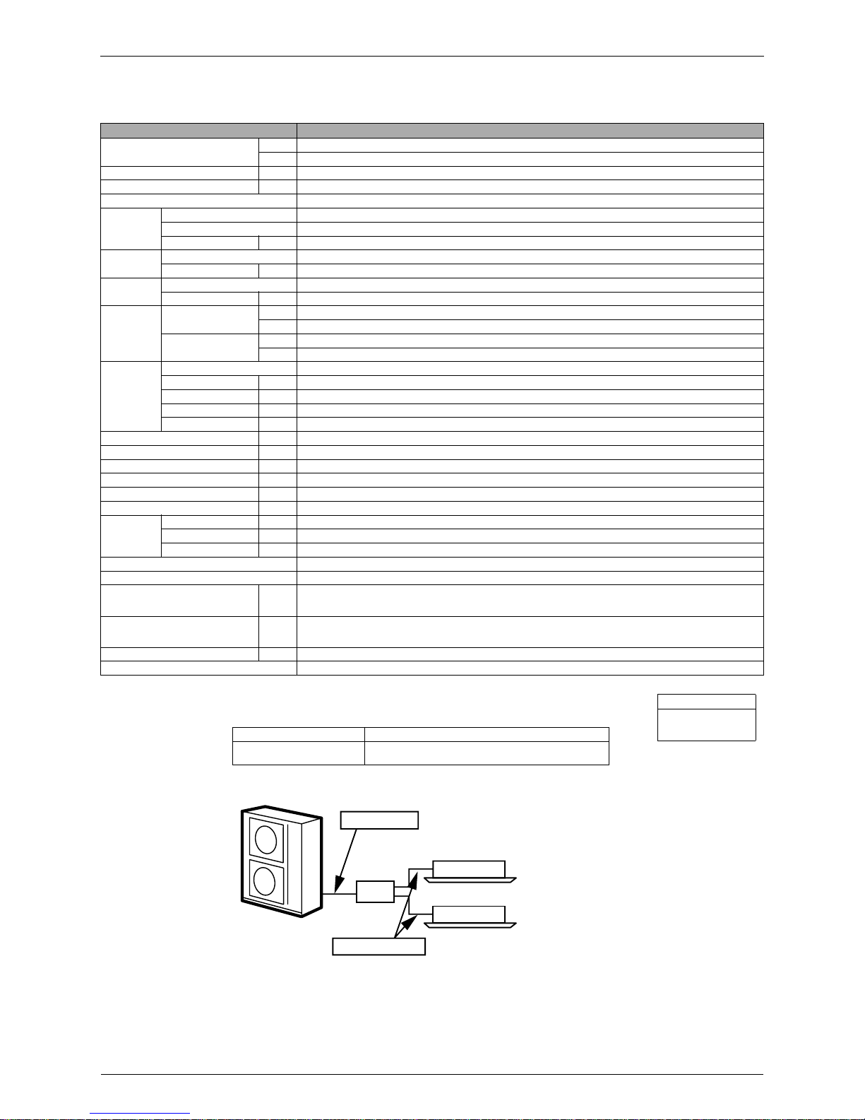
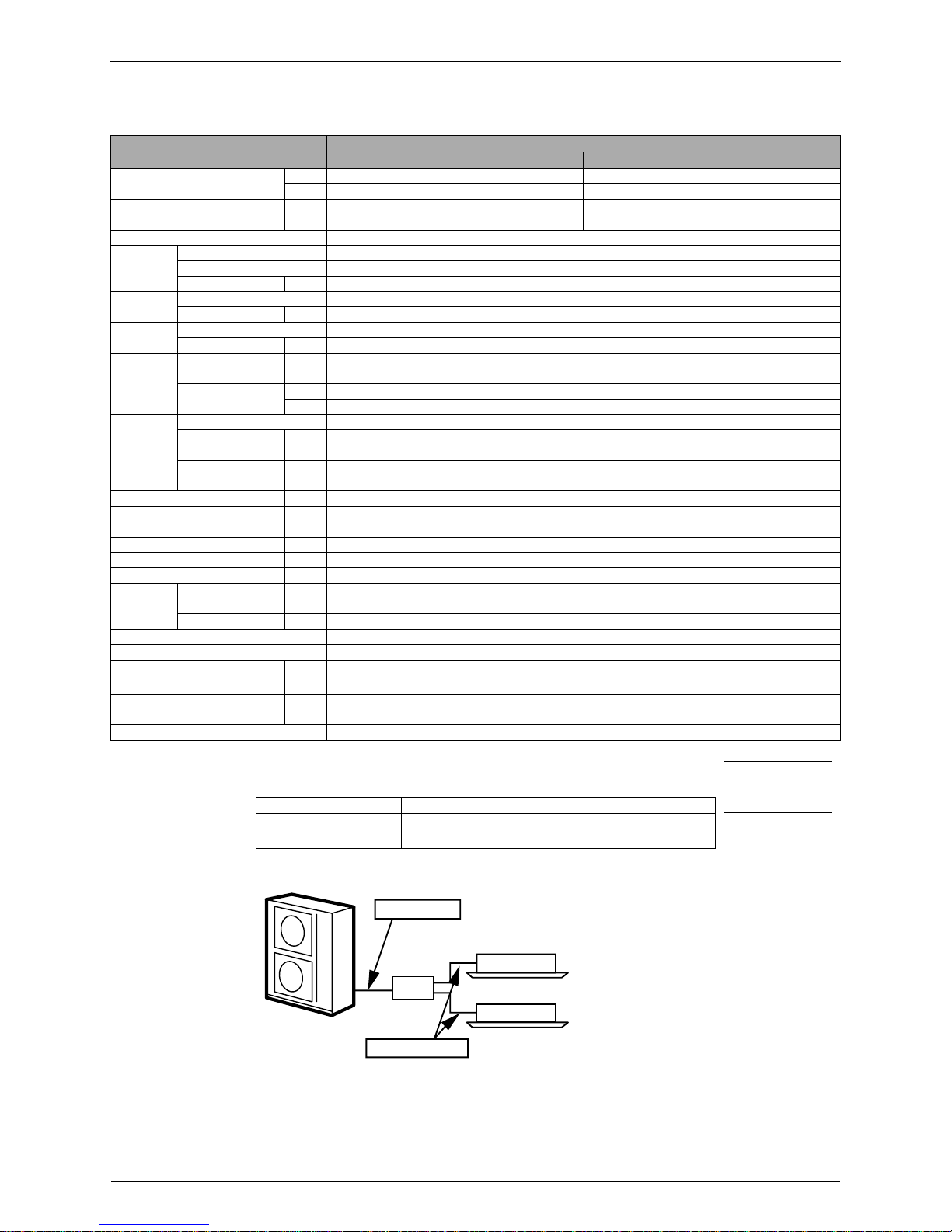
Cooling Piping Length
Indoor ; 27°CDB / 19.0°CWB
Outdoor ; 35°CDB
Main Piping : 5m
Branch Piping : 3m
(each indoor unit / 71 Class+60 Class)
Conversion Formulae
kcal/h=kW×860
Btu/h=kW×3414
cfm=m³/min×35.3
BP Unit
Outdoor Unit
Main Piping
Branch Piping
Indoor Unit
(Q0143)
Si18-201 Specifications
Specifications 11
Notes:
1.
★
Refer to Engineering Data Book.
2. The data are based on the conditions shown in the table below.
60Hz 220V
Model RMK140JVMT9
Cooling Capacity (19.5°CWB)
kW 14.5
kcal/h 12,500
Power Consumption
★
W 4,950
Running Current
★
A 23.0
Casing Color Ivory W h ite
Compressor
Type Hermetically Sealed Scroll Type (Oval Discharge)
Model JT100FBVD
Motor Output W 3,300
Refrigerant
Oil
Model SUNISO 4GSD.I.
Charge kg 1.5
Refrigerant
Type R22
Charge kg 9.9
Air Flow Rate
m³/min
H 114
L 104
cfm
H 4,024
L 3,671
Fan
Type Propeller
Motor Output W (Upper Side) H : 53 L : 38 (Lower Side) H : 41 L : 30
Running Current A (Upper Side) H : 0.50 L : 0.45 (Lower Side) H : 0.47 L : 0.42
Power Consumption W (Upper Side) H : 93.1 L : 78.8 (Lower Side) H : 81.3 L : 68.8
Power Factor % 100
Starting Current A 29.0
Dimensions (H×W×D) mm 1,345×880×320
Package Dimensions mm 918×394×1,397
Weight kg 134
Gross Weight kg 143
Operation Sound dBA 53
Piping
Connection
Liquid mm
φ
9.5 (Flare Connection)
Gas mm
φ
19.1 (Flare Connection)
Drain mm
φ
18
Heat Insulation Both Liquid and Gas Pipes
No. of Wiring Connection 3 for Power Supply, 4 for Interunit Wiring (Including Earth Wiring)
Max. Interunit Piping Length m
115 (Total Main Piping and Branch Piping)
55 (Total Main Piping), 60 (Total Branch Piping)
15 (Max. Length for Each Room)
Amount of Additional Charge g/m Chargeless
Max. Installation Height Difference m 30 (Between Indoor or BP Unit and Outdoor Unit), 15 (Between Indoor or BP Units)
Drawing No. 3D030949A
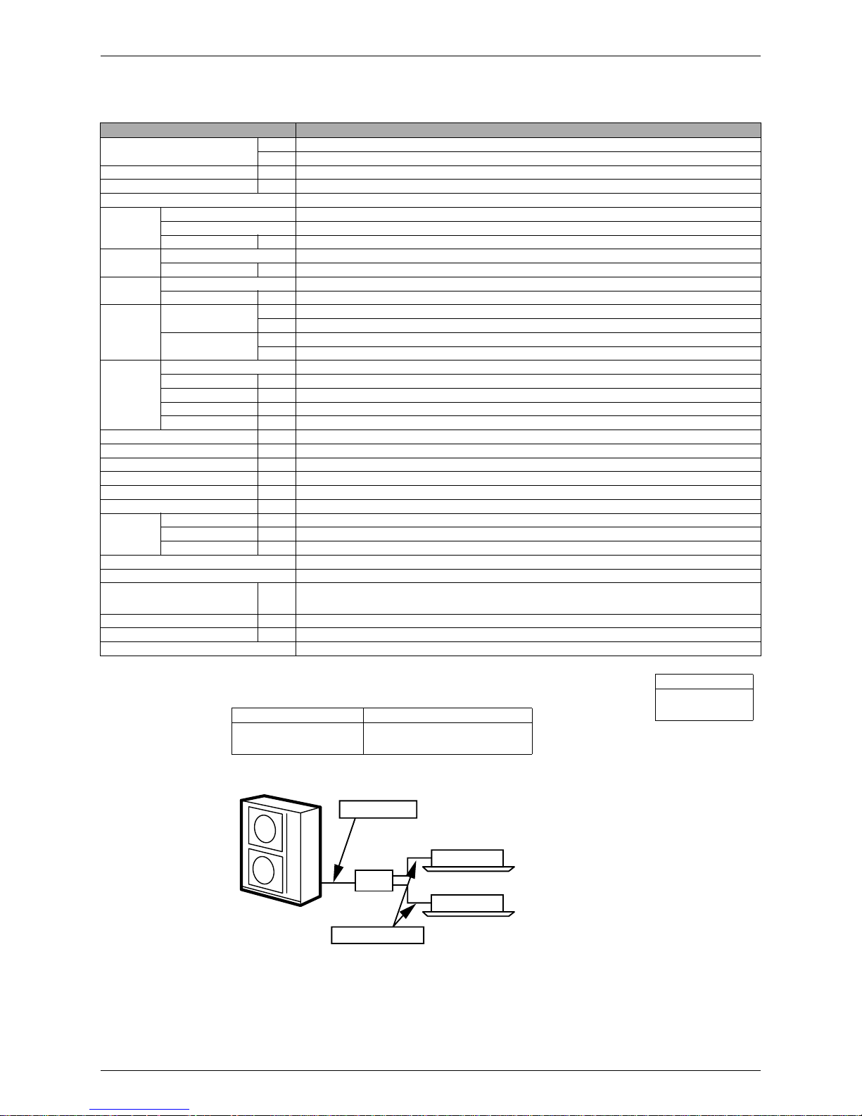
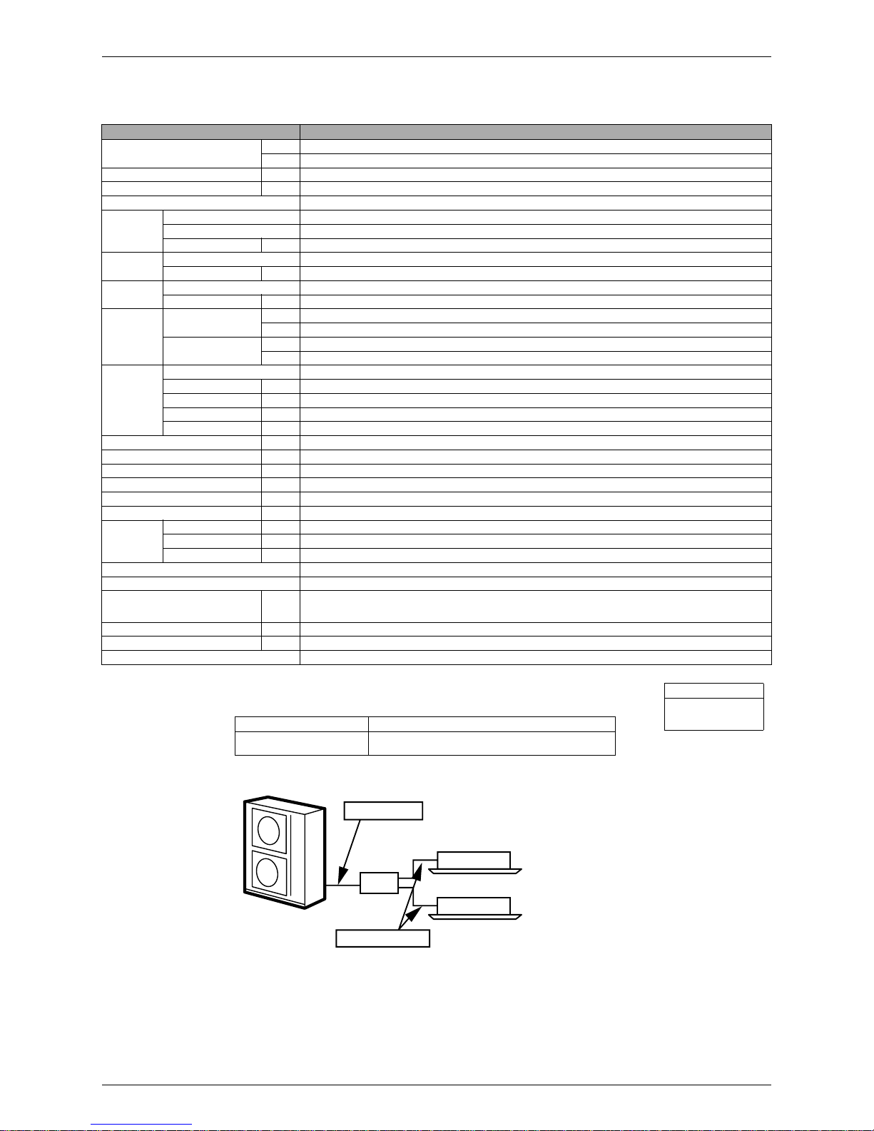
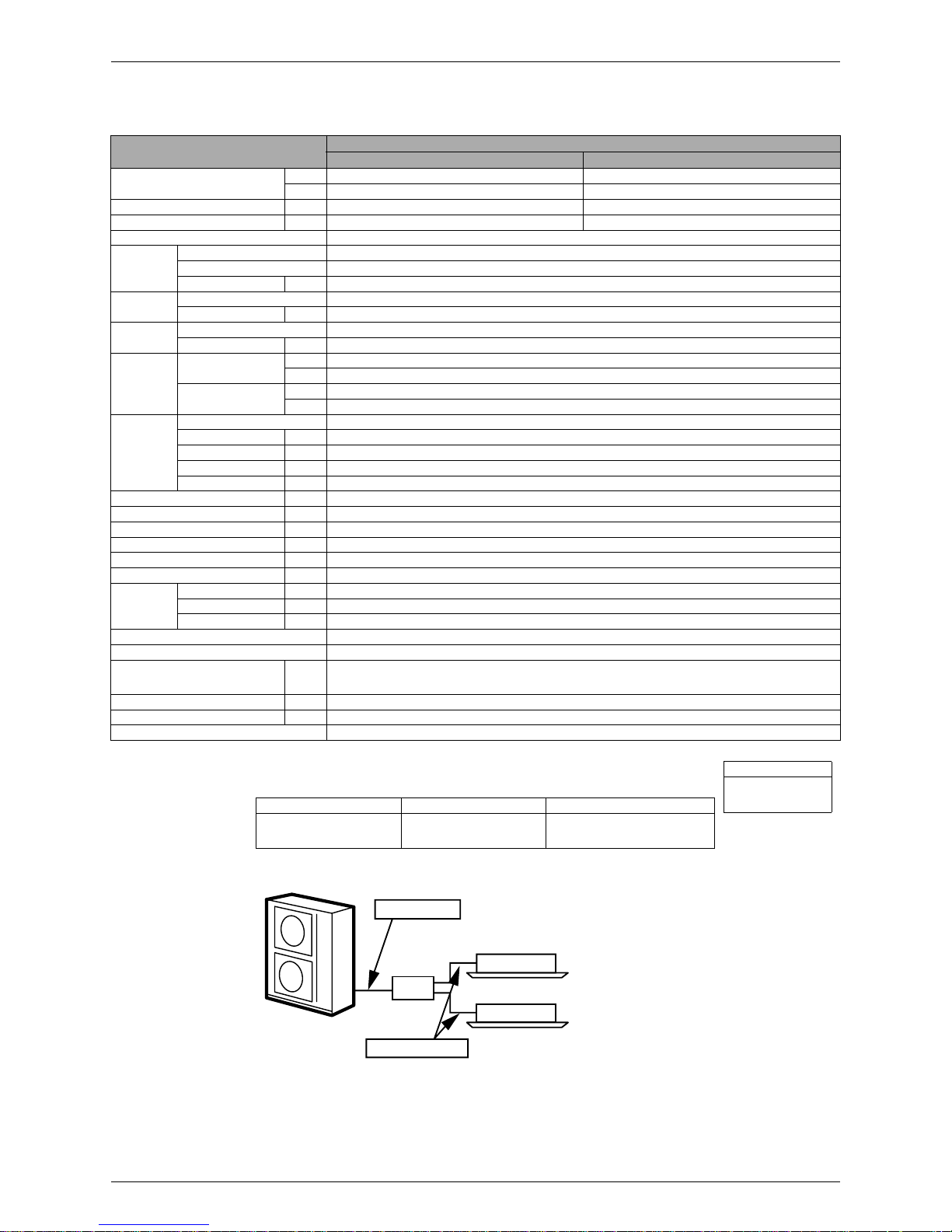
Cooling Piping Length
Indoor ; 27°CDB / 19.5°CWB
Outdoor ; 35°CDB
Main Piping : 5m
Branch Piping : 3m
(each indoor unit / 71 Class+60 Class)
Conversion Formulae
kcal/h=kW×860
Btu/h=kW×3414
cfm=m³/m in ×35.3
BP Unit
Outdoor Unit
Main Piping
Branch Piping
Indoor Unit
(Q0143)
Specifications Si18-201
12 Specifications
Notes:
1.
★
Refer to Engineering Data Book.
2. The data are based on the conditions shows in the table below.
50Hz 220-230-240V / 60Hz 220-230V
Model RMK140JAVM
Cooling Capacity (19.0°CWB)
kW 14.5
kcal/h 12,470
Power Consumption
★
W 4,650
Running Current
★
A 20.4
Casing Color Ivory W h ite
Compressor
Type Hermetically Sealed Scroll Type (Oval Discharge)
Model JT100FBVD
Motor Output W 3,300
Refrigerant
Oil
Model SUNISO 4GSD.I.
Charge kg 1.5
Refrigerant
Type R22
Charge kg 4.5
Air Flow Rate
m³/min
H 114
L 104
cfm
H 4,024
L 3,671
Fan
Type Propeller
Motor Output W (Upper Side) H : 53 L : 38 (Lower Side) H : 41 L : 30
Running Current A (Upper Side) H : 0.50 L : 0.45 (Lower Side) H : 0.47 L : 0.42
Power Consumption W (Upper Side) H : 93.1 L : 78.8 (Lower Side) H : 81.3 L : 68.8
Power Factor % 100
Starting Current A 29.0
Dimensions (H×W×D) mm 1,345×880×320
Package Dimensions (W×D×H) mm 918×394×1,397
Weight kg 111
Gross Weight kg 120
Operation Sound dBA 50
Piping
Connection
Liquid mm
φ
9.5 (Flare Connection)
Gas mm
φ
19.1 (Flare Connection)
Drain mm
φ
18
Heat Insulation Both Liquid and Gas Pipes
No. of Wiring Connection 3 For Power Supply, 4 For Interunit Wiring
Max. Interunit Piping Length m
110 (Total Main Piping and Branch PIping)
30 (Total Main Piping), 60 (Total Branch Piping)
20 (Max. Length for Each Room)
Amount of Additional Charge g/m
Additional refrigerant to be charge : R (kg)
R= (Total length of the liquid pipe-line of
φ
9.5) ×0.05 + (Total length of the liquid pipe-line of φ6.4) × 0.025
∗
If the value of “R” is less than 0.5, additional charging of refrigerant is unnecessary.
Max. Installation Height Difference m 15 (Between Indoor or BP Unit and Outdoor Unit), 10 (Both between Indoor Units and BP Units)
Drawing No. 3D033202
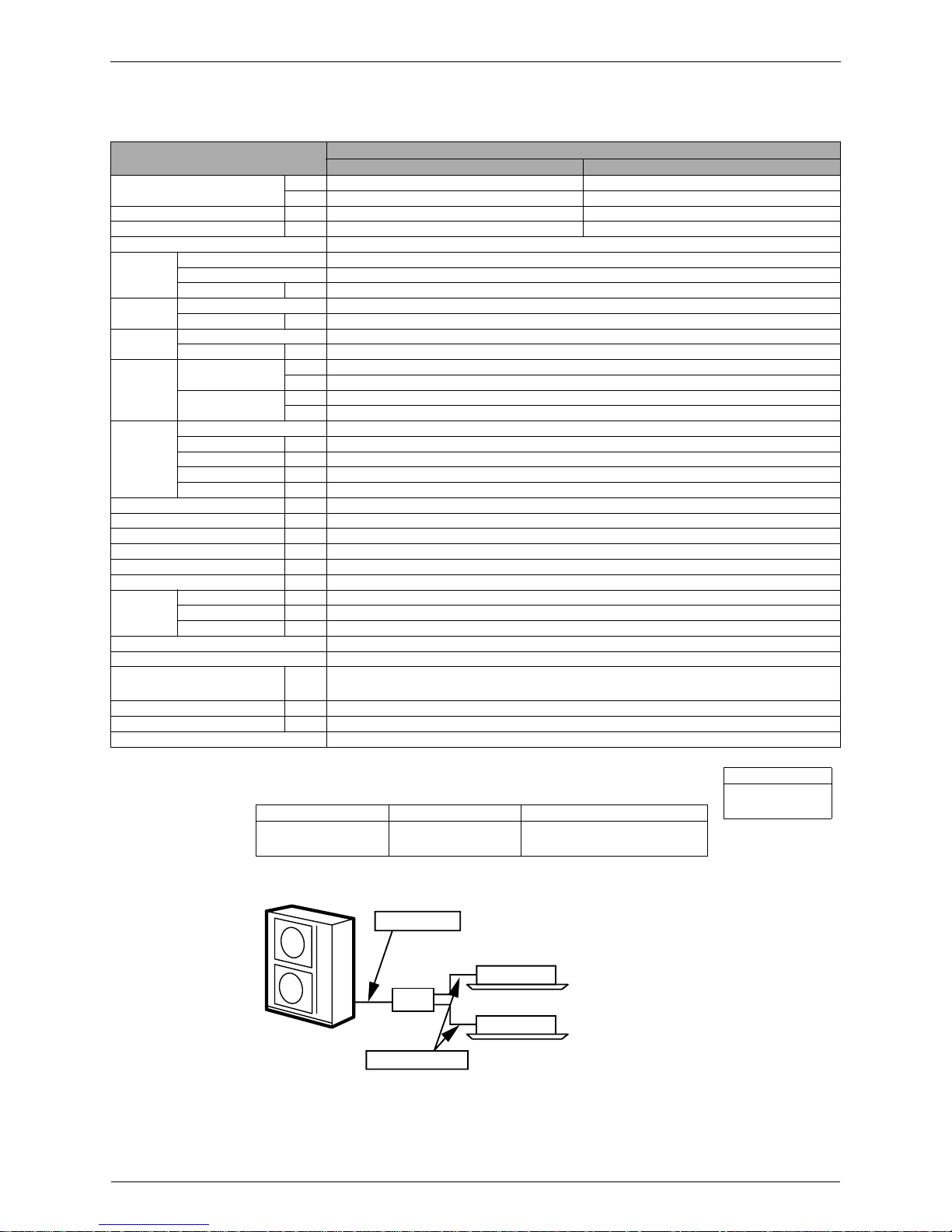
Cooling Piping Length
Indoor ; 27°CDB / 19.0°CWB
Outdoor ; 35°CDB
Main Piping : 5m
Branch Piping : 3m (each indoor unit / 71 Class+60 Class)
Conversion Formulae
kcal/h=kW×860
Btu/h=kW×3414
cfm=m³/m in ×35.3
BP Unit
Outdoor Unit
Main Piping
Branch Piping
Indoor Unit
(Q0143)
Si18-201 Specifications
Specifications 13
Notes:
1.
★
Refer to Engineering Data Book.
2. The data are based on the conditions shows in the table below.
50Hz 220-230-240V / 60Hz 220-230V
Model RM K140JZVMA
Cooling Capacity (19.0°CWB)
kW 14.5
kcal/h 12,470
Power Consumption
★
W 5,000
Running Current
★
A 23.2-22.2-21.3
Casing Color Ivory W h ite
Compressor
Type Hermetically Sealed Scroll Type (Oval Discharge)
Model JT100FAVD
Motor Output W 3,300
Refrigerant
Oil
Model DAPHNE FVC68D
Charge kg 1.5
Refrigerant
Type R407C
Charge kg 9.9
Air Flow Rate
m³/min
H 114
L 104
cfm
H 4,024
L 3,671
Fan
Type Propeller
Motor Output W (Upper Side) H : 53 L : 38 (Lower Side) H : 41 L : 30
Running Current A (Upper Side) H : 0.50 L : 0.45 (Lower Side) H : 0.47 L : 0.42
Power Consumption W (Upper Side) H : 93.1 L : 78.8 (Lower Side) H : 81.3 L : 68.8
Power Factor % 100
Starting Current A 29.0
Dimensions (H×W×D) mm 1,345×880×320
Package Dimensions (W×D×H) mm 918×394×1,397
Weight kg 134
Gross Weight kg 143
Operation Sound dBA 53
Piping
Connection
Liquid mm
φ
9.5 (Flare Connection)
Gas mm
φ
19.1 (Flare Connection)
Drain mm
φ
18
Heat Insulation Both Liquid and Gas Pipes
No. of Wiring Connection 3 For Power Supply, 4 For Interunit Wiring (Included Earth Wiring)
Max. Interunit Piping Length m
115 (Total Main Piping and Branch PIping)
55 (Total Main Piping), 60 (Total Branch Piping)
15 (Max. Length for Each Room)
Amount of Additional Charge g/m Chargeless
Max. Installation Height Difference m 30 (Between Indoor or BP Unit and Outdoor Unit), 15 (Both between Indoor Units and BP Units)
Drawing No. 3D031579
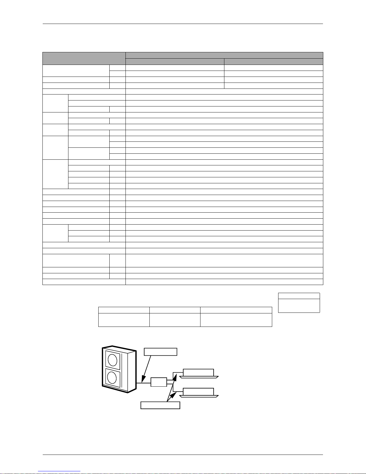
Cooling Piping Length
Indoor ; 27°CDB / 19.0°CWB
Outdoor ; 35°CDB
Main Piping : 5m
Branch Piping : 3m (each indoor unit / 71 Class+60 Class)
Conversion Formulae
kcal/h=kW×860
Btu/h=kW×3414
cfm=m³/m in ×35.3
BP Unit
Outdoor Unit
Main Piping
Branch Piping
Indoor Unit
(Q0143)
Specifications Si18-201
14 Specifications
1.1.2 Heat Pump
Notes:
1.
★
Refer to Engineering Data Book.
2. The data are based on the conditions shown in the table below.
50Hz 220-240V / 60Hz 220-230V
Model
RMX140JVMC9 (8)
Cooling Heating
Cooling Capacity (19.0°CWB)
kW 14.5 16.5
kcal/h 12,470 14,190
Power Consumption
★
W 5,000 5,780
Running Current
★
A 23.2 26.8
Casing Color Ivory W h ite
Compressor
Type Hermetically Sealed Scroll Type (Oval Discharge)
Model JT100FBVD
Motor Output W 3,300
Refrigerant
Oil
Model SUNISO 4GSD.I.
Charge L 1.5
Refrigerant
Type R22
Charge kg 9.9
Air Flow Rate
m³/min
H 114
L 104
cfm
H 4,024
L 3,671
Fan
Type Propeller
Motor Output W (Upper Side) H : 53 L : 38 (Lower Side) H : 41 L : 30
Running Current A (Upper Side) H : 0.50 L : 0.45 (Lower Side) H : 0.47 L : 0.42
Power Consumption W (Upper Side) H : 93.1 L : 78.8 (Lower Side) H : 81.3 L : 68.8
Power Factor % 100
Starting Current A 29.0
Dimensions (H×W×D) mm 1,345×880×320
Package Dimensions mm 918×394×1,397
Weight kg 136
Gross Weight kg 145
Operation Sound dBA 53
Piping
Connection
Liquid mm
φ
9.5 (Flare Connection)
Gas mm
φ
19.1 (Flare Connection)
Drain mm
φ
18
Heat Insulation Both Liquid and Gas Pipes
No. of Wiring Connection 3 for Power Supply, 4 for Interunit Wiring (Including Earth Wiring)
Max. Interunit Piping Length m
115 (Total Main Piping and Branch Piping)
55 (Total Main Piping), 60 (Total Branch Piping)
15 (Max. Length for Each Room)
Amount of Additional Charge g/m Chargeless
Max. Installation Height Difference m 30 (Between Indoor or BP Unit and Outdoor Unit), 15 (Between Indoor or BP Units)
Drawing No. 3D030946A
Cooling Heating Piping Length
Indoor ; 27°CDB / 19.0°CWB
Outdoor ; 35°CDB
Indoor ; 21°CDB
Outdoor ; 7°CDB / 6°CWB
Main Piping : 5m
Branch Piping : 3m
(each indoor unit / 71 Class+60 Class)
Conversion Formulae
kcal/h=kW×860
Btu/h=kW×3414
cfm=m³/m in ×35.3
BP Unit
Outdoor Unit
Main Piping
Branch Piping
Indoor Unit
(Q0143)
Si18-201 Specifications
Specifications 15
Notes:
1.
★
Refer to Engineering Data Book.
2. The data are based on the conditions shown in the table below.
60Hz 220-230V
Model
RMX140JVMT9
Cooling Heating
Cooling Capacity (19.5°CWB)
kW 14.5 16.5
kcal/h 12,500 14,200
Power Consumption
★
W 4,950 5,870
Running Current
★
A 23.0 27.2
Casing Color Ivory W h ite
Compressor
Type Hermetically Sealed Scroll Type (Oval Discharge)
Model JT100FBVD
Motor Output W 3,300
Refrigerant
Oil
Model SUNISO 4GSD.I.
Charge L 1.5
Refrigerant
Type R22
Charge kg 9.9
Air Flow Rate
m³/min
H 114
L 104
cfm
H 4,024
L 3,671
Fan
Type Propeller
Motor Output W (Upper Side) H : 53 L : 38 (Lower Side) H : 41 L : 30
Running Current A (Upper Side) H : 0.50 L : 0.45 (Lower Side) H : 0.47 L : 0.42
Power Consumption W (Upper Side) H : 93.1 L : 78.8 (Lower Side) H : 81.3 L : 68.8
Power Factor % 100
Starting Current A 29.0
Dimensions (H×W×D) mm 1,345×880×320
Package Dimensions mm 918×394×1,397
Weight kg 136
Gross Weight kg 145
Operation Sound dBA 53
Piping
Connection
Liquid mm
φ
9.5 (Flare Connection)
Gas mm
φ
19.1 (Flare Connection)
Drain mm
φ
18
Heat Insulation Both Liquid and Gas Pipes
No. of Wiring Connection 3 for Power Supply, 4 for Interunit Wiring (Including Earth Wiring)
Max. Interunit Piping Length m
115 (Total Main Piping and Branch Piping)
55 (Total Main Piping), 60 (Total Branch Piping)
15 (Max. Length for Each Room)
Amount of Additional Charge g/m Chargeless
Max. Installation Height Difference m 30 (Between Indoor or BP Unit and Outdoor Unit), 15 (Between Indoor or BP Units)
Drawing No. 3D030947A
Cooling Heating Piping Length
Indoor ; 27°CDB / 19.5°CWB
Outdoor ; 35°CDB
Indoor ; 21°CDB
Outdoor ; 7°CDB / 6°CWB
Main Piping : 5m
Branch Piping : 3m
(each indoor unit / 71 Class+60 Class)
Conversion Formulae
kcal/h=kW×860
Btu/h=kW×3414
cfm=m³/m in ×35.3
BP Unit
Outdoor Unit
Main Piping
Branch Piping
Indoor Unit
(Q0143)
Specifications Si18-201
16 Specifications
Notes:
1.★ Refer to Engineering Data Book.
2. The data are based on the conditions shown in the table below.
50Hz 220-240V / 60Hz 220-230V
Model
RMX140JVMB
Cooling Heating
Cooling Capacity (19.0°CWB)
kW 14.5 16.5
kcal/h 12,470 14,190
Power Consumption
★
W 5,000 5,780
Running Current
★
A 23.2 26.8
Casing Color Ivory W h ite
Compressor
Type Hermetically Sealed Scroll Type (Oval Discharge)
Model JT100FBVD
Motor Output W 3,300
Refrigerant
Oil
Model SUNISO 4GSD.I.
Charge L 1.5
Refrigerant
Type R22
Charge kg 9.9
Air Flow Rate
m³/min
H 114
L 104
cfm
H 4,024
L 3,671
Fan
Type Propeller
Motor Output W (Upper Side) H : 53 L : 38 (Lower Side) H : 41 L : 30
Running Current A (Upper Side) H : 0.50 L : 0.45 (Lower Side) H : 0.47 L : 0.42
Power Consumption W (Upper Side) H : 93.1 L : 78.8 (Lower Side) H : 81.3 L : 68.8
Power Factor % 100
Starting Current A 29.0
Dimensions (H×W×D) mm 1,345×880×320
Package Dimensions (W×D×H) mm 918×394×1,397
Weight kg 136
Gross Weight kg 145
Operation Sound dBA 53
Piping
Connection
Liquid mm
φ
9.5 (Flare Connection)
Gas mm
φ
19.1 (Flare Connection)
Drain mm
φ
18
Heat Insulation Both Liquid and Gas Pipes
No. of Wiring Connection 3 For Power Supply, 4 For Interunit Wiring (Included Earth Wiring)
Max. Interunit Piping Length m
115 (Total Main Piping and Branch PIping)
55 (Total Main Piping), 60 (Total Branch Piping)
15 (Max. Length for Each Room)
Amount of Additional Charge g/m Chargeless
Max. Installation Height Difference m 30 (Between Indoor or BP Unit and Outdoor Unit), 15 (Both between Indoor Units and BP Units)
Drawing No. 3D030950A
Cooling Heating Piping Length
Indoor ; 27°CDB / 19.0°CWB
Outdoor ; 35°CDB
Indoor ; 20°CDB
Outdoor ; 7°CDB / 6°CWB
Main Piping : 5m
Branch Piping : 3m
(each indoor unit / 71 Class+60 Class)
Conversion Formulae
kcal/h=kW×860
Btu/h=kW×3414
cfm=m³/m in ×35.3
BP Unit
Outdoor Unit
Main Piping
Branch Piping
Indoor Unit
(Q0143)
Si18-201 Specifications
Specifications 17
Notes:
1.
★
Refer to Engineering Data Book.
2. The data are based on the conditions shows in the table below.
50Hz 220-230-240V / 60Hz 220-230V
Model
RMX140JZVMB
Cooling Heating
Cooling Capacity (19.0°CWB)
kW 14.5 16.5
kcal/h 12,470 14,190
Power Consumption
★
W 5,000 6,050
Running Current
★
A 23.2-22.2-21.3 28.1-26.8-25.7
Casing Color Ivory W h ite
Compressor
Type Hermetically Sealed Scroll Type (Oval Discharge)
Model JT100FAVD
Motor Output W 3,300
Refrigerant
Oil
Model DAPHNE FVC68D
Charge L 1.5
Refrigerant
Type R407C
Charge kg 9.9
Air Flow Rate
m³/min
H 114
L 104
cfm
H 4,024
L 3,671
Fan
Type Propeller
Motor Output W (Upper Side) H : 53 L : 38 (Lower Side) H : 41 L : 30
Running Current A (Upper Side) H : 0.50 L : 0.45 (Lower Side) H : 0.47 L : 0.42
Power Consumption W (Upper Side) H : 93.1 L : 78.8 (Lower Side) H : 81.3 L : 68.8
Power Factor % 100
Starting Current A 29.0
Dimensions (H×W×D) mm 1,345×880×320
Package Dimensions (W×D×H) mm 918×394×1,397
Weight kg 136
Gross Weight kg 145
Operation Sound dBA 53
Piping
Connection
Liquid mm
φ
9.5 (Flare Connection)
Gas mm
φ
19.1 (Flare Connection)
Drain mm
φ
18
Heat Insulation Both Liquid and Gas Pipes
No. of Wiring Connection 3 For Power Supply, 4 For Interunit Wiring (Included Earth Wiring)
Max. Interunit Piping Length m
115 (Total Main Piping and Branch Piping)
55 (Total Main Piping), 60 (Total Branch Piping)
15 (Max. Length for Each Room)
Amount of Additional Charge g/m Chargeless
Max. Installation Height Difference m 30 (Between Indoor or BP Unit and Outdoor Unit), 15 (Both between Indoor Units and BP Units)
Drawing No. 3D031578
Cooling Heating Piping Length
Indoor ; 27°CDB / 19.0°CWB
Outdoor ; 35°CDB
Indoor ; 21°CDB
Outdoor ; 7°CDB / 6°CWB
Main Piping : 5m
Branch Piping : 3m
(each indoor unit / 71 Class+60 Class)
Conversion Formulae
kcal/h=kW×860
Btu/h=kW×3414
cfm=m³/m in ×35.3
BP Unit
Outdoor Unit
Main Piping
Branch Piping
Indoor Unit
(Q0143)
 Loading...