

Daikin FTXC25AV1B, RXC25AV1B, FTXC35AV1B, RXC35AV1B, FTXC50AV1B Installation manuals
...
INSTALLATION AND
MAINTENANCE MANUAL
R32 SPLIT SERIES
MODELS
FTXC25AV1B RXC25AV1B
FTXC35AV1B RXC35AV1B
FTXC50AV1B RXC50AV1B
FTXC60AV1B RXC60AV1B
Installation Manual
R32 Split Series
Manuale d’installazione
Serie Multiambienti R32
Installationsanleitung
Split-Baureihe R32
Manual de instalación
Serie Split R32
Manuel d’installation
Série split R32
Montaj kýlavuzlarý
R32 Split serisi
Руководство по монтажу
Серия R32 с раздельной установкой
English
Italiano
Deutsch
Español
Français
Türkçe
Русский
Еγχειρίδιο εγκατάστασης
Σειρά Split R32
IM-3WMYJ(R)-0816(0)-DAIKIN
Part Number.: R08019045616
Еλληνικă

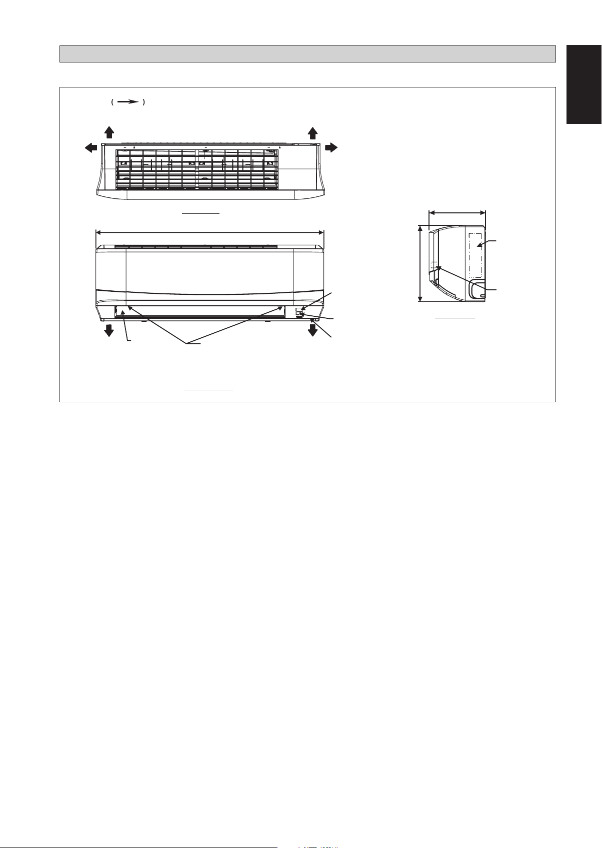
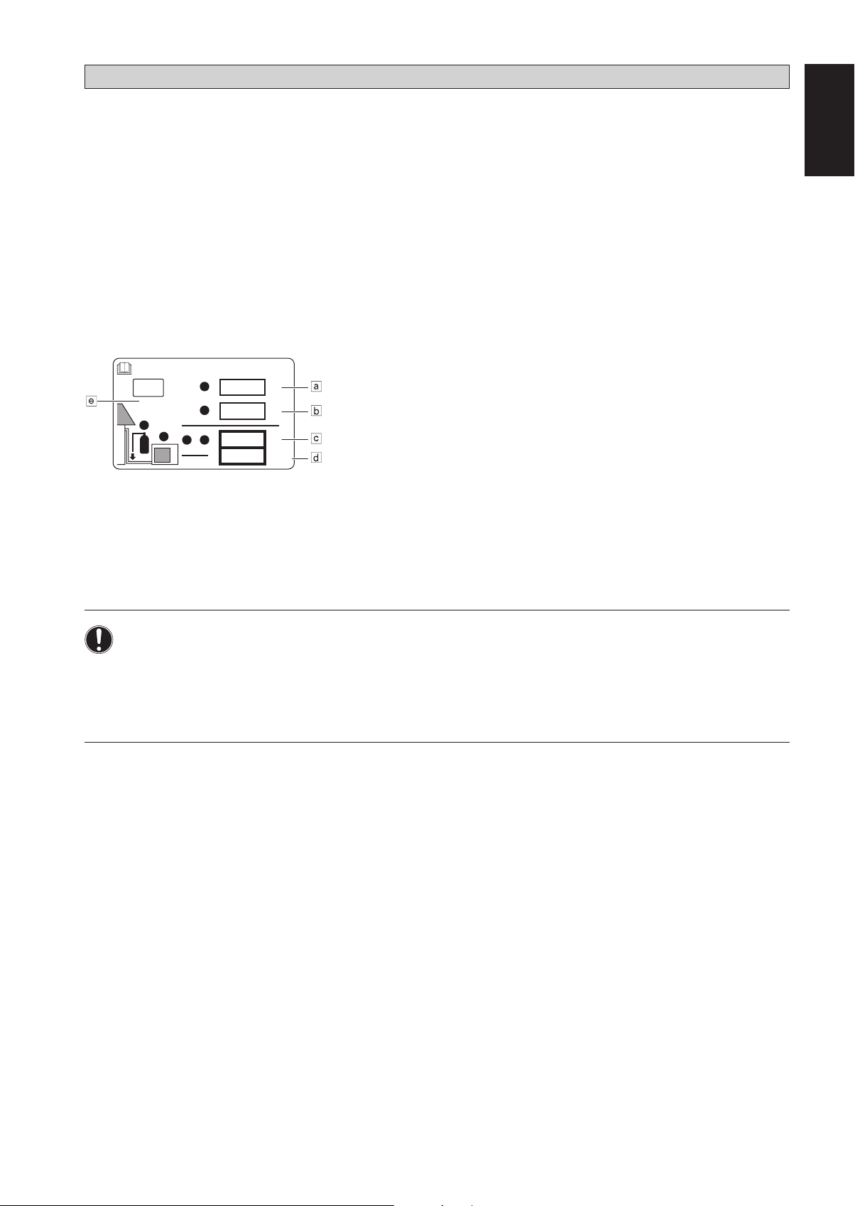
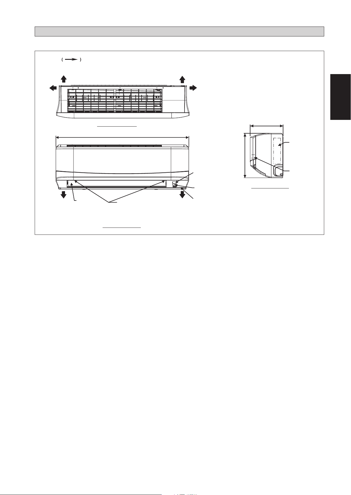
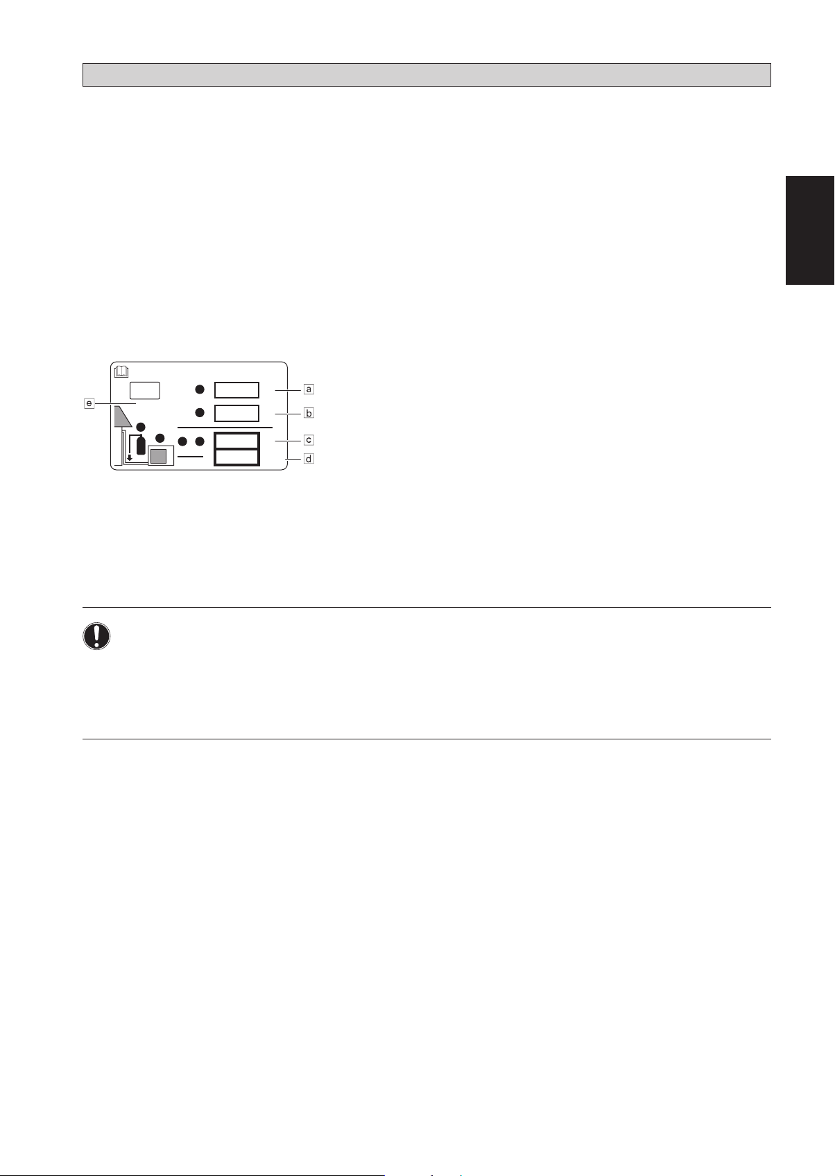
Indoor Unit [FTXC]
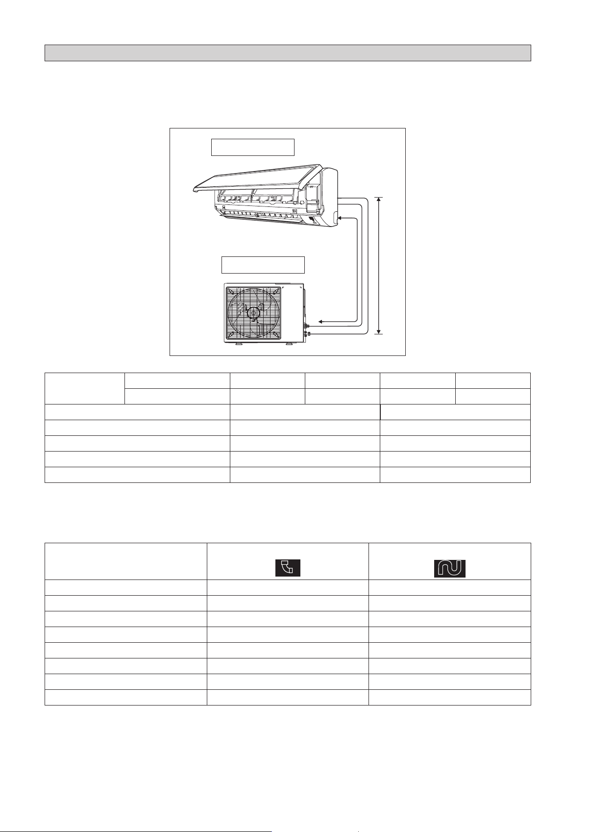
OUTLINE AND DIMENSIONS
THE MARK SHOWS PIPING DIRECTION
REAR REAR RIGHTLEFT
TOP VIEW
A
BOTTOM BOTTOM
LOUVER
FRONT GRILLE
FIXED SCREWS
(INSIDE)
FRONT VIEW
SIGNAL RECEIVER
INDOOR UNIT
ON/OFF SWITCH
ROOM TEMPERATURE
THERMISTOR
(INSIDE)
English
Original Instruction
C
STICKER
SERIAL NO.
B
TERMINAL
BLOCK
WITH EARTH
TERMINAL
SIDE VIEW
1-1
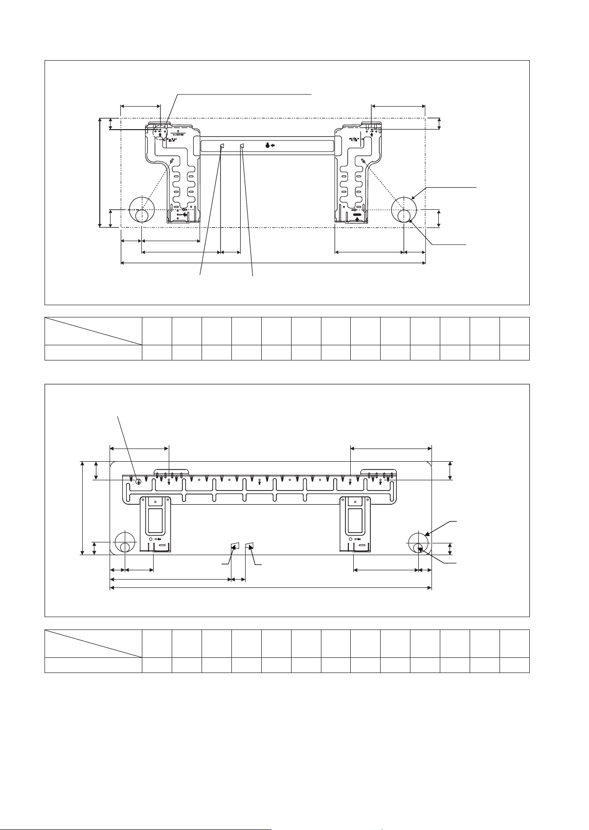
Indoor Unit [FTXC]
« Recommended mounting plate retention spots
(5 spots in all)
D
E
F
B
G
JH
ML
A
Liquid pipe end
Gas pipe end
F
Through the wall
hole Ø 65mm
G
Drain hose position
IK
All dimensions are in mm
Dimension
Model
ABCDE FGHI JKLM
25/35 859 288 209 104 141 30 46 55 56 153 181 207 52
Indoor Unit [FTXC]
« Recommended mounting plate retention spots
(7 spots in all)
D
F
B
G
H
J
Liquid pipe end
L
M
Gas pipe end
A
E
F
Through the wall
hole Ø 65mm
G
K
I
Drain hose position
All dimensions are in mm
Dimension
Model
ABCDE FGHI JKLM
50/60 1124 310 237 190 173 61 40 45 48 91 219 580 45
1-2
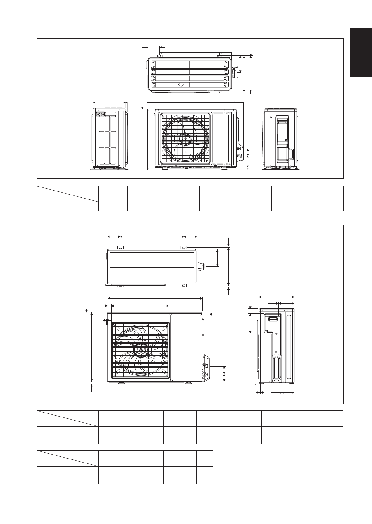
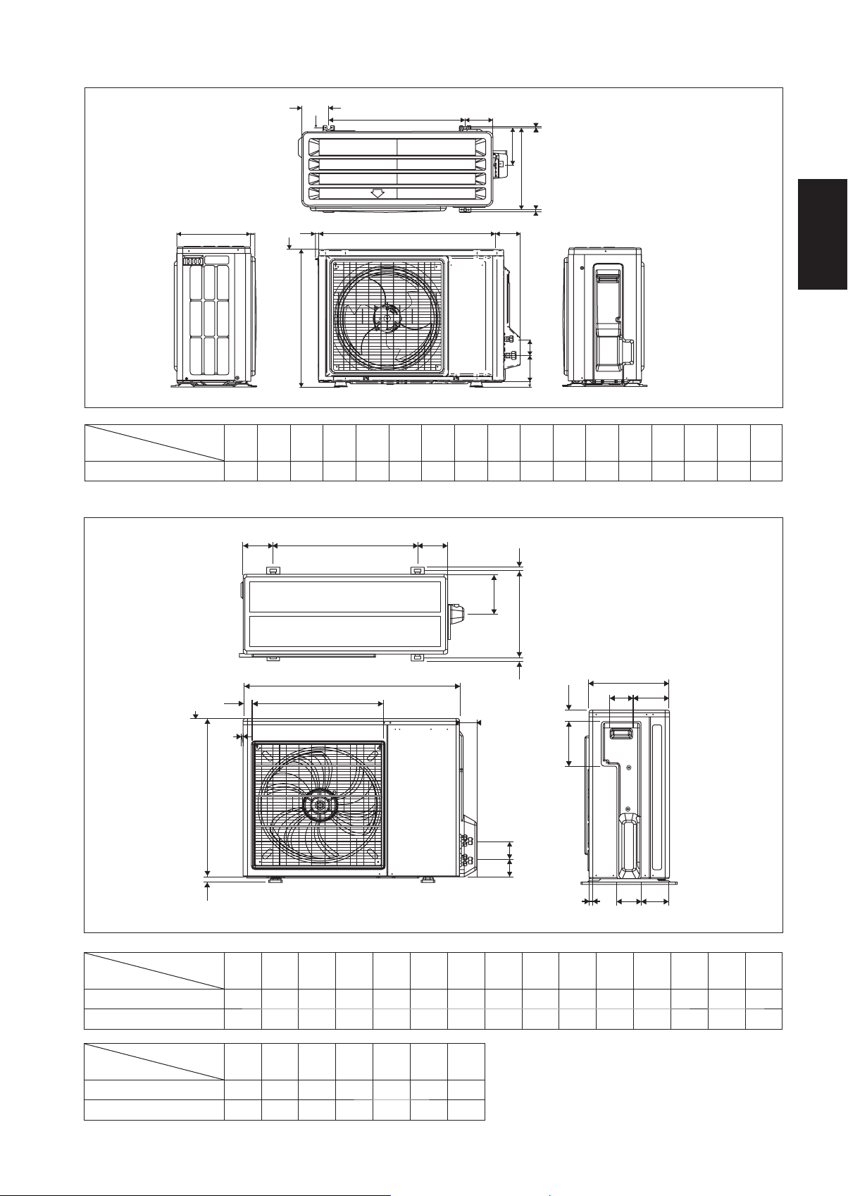
Outdoor Unit [RXC]
Model
Dimension
J
G
EF
ABCDE FGHI JKLMNOPQ
2.0
A
HI
N
Q
B
CD
All dimensions are in mm
OP
KL
M
25/35 550 658 51 11 273 16 14 470 96 93 94 60 14 133 8 10 299
Outdoor Unit [RXC]
English
3.0
KLL
N
M
Q
A
O
V
B
P
D
U
N
F
E
S
R
All dimensions are in mm
C
GH
I
J
T
Dimension
Model
ABCDE FGHI JKLMNO
50 855 628 328 520 179 46 93 149 101 113 603 126 164 15 34
60 855 730 328 520 179 46 93 149 101 113 603 126 164 15 34
Dimension
Model
PQRS TUV
50 23 362 73 75 8 67 7
60 23 362 73 75 8 67 7
1-3

INSTALLATION MANUAL
This manual provides the procedures of installation to ensure a safe and good standard of operation for the air conditioner unit.
Special adjustment may be necessary to suit local requirement.
Before using your air conditioner, please read this instruction manual carefully and keep it for future reference.
This appliance is intended to be used by expert or trained users in shops, in light industry and on farms, or for commercial use by lay
persons.
This appliance is not intended for use by persons, including children, with reduced physical, sensory or mental capabilities, or lack of
experience and knowledge, unless they have been given supervision or instruction concerning use of the appliance by a person responsible
for their safety.
Children should be supervised to ensure that they do not play with the appliance.
SAFETY PRECAUTIONS
! WARNING ! CAUTION
Installation and maintenance should be performed by qualified
•
persons who are familiar with local code and regulation, and
experienced with this type of appliance.
All field wiring must be installed in accordance with the national
•
wiring regulation.
Ensure that the rated voltage of the unit corresponds to that of
•
the name plate before commencing wiring work according to the
wiring diagram.
The unit must be GROUNDED to prevent possible hazard due
•
to insulation failure.
All electrical wiring must not touch the water piping or any moving
•
parts of the fan motors.
Confirm that the unit has been switched OFF before installing or
•
servicing the unit.
Disconnect from the main power supply before servicing the air
•
conditioner unit.
DO NOT pull out the power cord when the power is ON. This
•
may cause serious electrical shocks which may result in the fire
hazards.
Keep the indoor and outdoor units, power cable and transmission
•
wiring, at least 1m from TVs and radios, to prevent distorted
pictures and static. {Depending on the type and source of the
electrical waves, static may be heard even when more than 1m
away}.
WARNING
Do not use means to accelerate the defrosting process (if applicable)
or to clean, other than those recommended by the manufacturer. The
appliance shall be stored in a room without continuously operating
ignition sources (for example: open flames, an operating gas appliance
or an operating electric heater). Do not pierce or burn. Be aware that
refrigerants may not contain an odour. Appliance shall be installed,
operated and stored in a room with a floor area larger than Xm
(refer to page 13).
NOTE: The manufacturer may provide other suitable examples or may
provide additional information about the refrigerant odour.
Please take note of the following important points when
installing.
Do not install the unit where leakage of flammable gas may
•
occur.
If gas leaks and accumulates around the unit, it may cause
fire ignition.
Ensure that drainage piping is connected properly.
•
If the drainage piping is not connected properly, it may cause
water leakage which will dampen the furniture.
Do not overcharge the unit.
•
This unit is factory pre-charged. Overcharge will cause
over-current or damage to the compressor.
Ensure that the unit’s panel is closed after service or
•
installation.
Unsecured panels will cause the unit to operate noisily.
Sharp edges and coil surfaces are potential locations which
•
may cause injury hazards. Avoid from being in contact with
these places.
Before turning off the power supply set the remote controller’s
•
ON/OFF switch to the “OFF” position to prevent the nuisance
tripping of the unit. If this is not done, the unit’s fans will start
turning automatically when power resumes, posing a hazard to
service personnel or the user.
Do not install the units at or near doorway.
•
Do not operate any heating apparatus too close to the air
•
conditioner unit or use in room where mineral oil, oil vapour
or oil steam exist, this may cause plastic part to melt or deform
as a result of excessive heat or chemical reaction.
When the unit is used in kitchen, keep flour away from going
•
into suction of the unit.
This unit is not suitable for factory used where cutting oil mist
•
or iron powder exist or voltage fluctuates greatly.
Do not install the units at area like hot spring or oil refinery
•
2
plant where sulphide gas exists.
Ensure the color of wires of the outdoor unit and the terminal
•
markings are same to the indoors respectively.
IMPORTANT : DO NOT INSTALL OR USE THE AIR
•
CONDITIONER UNIT IN A LAUNDRY ROOM.
Do not use joined and twisted wires for incoming power
•
supply.
The equipment is not intended for use in a potentially explosive
•
atmosphere.
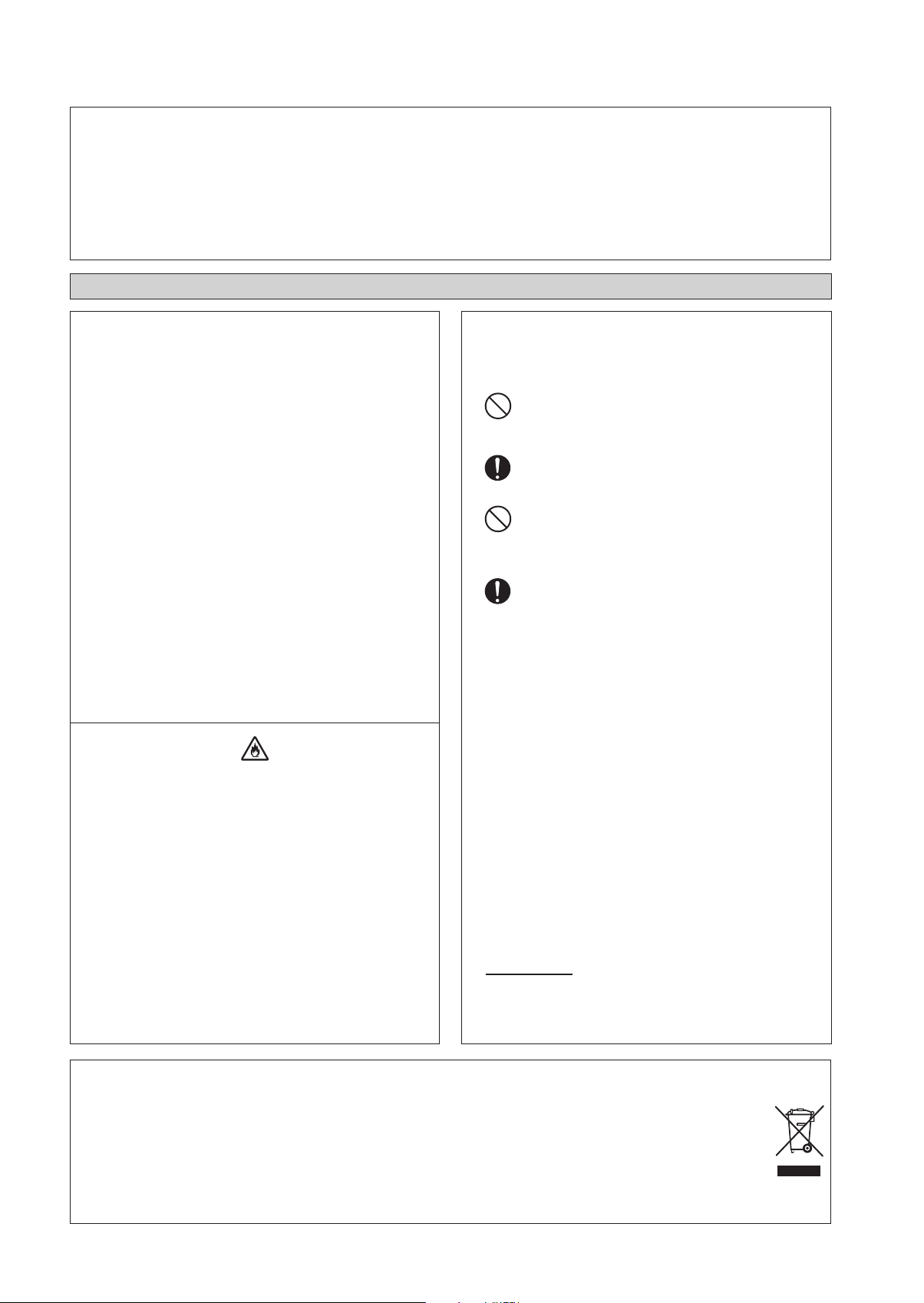
Disposal requirements
NOTICE
Your air conditioning product is marked with this symbol. This means that electrical and electronic products shall not be mixed with
unsorted household waste.
Do not try to dismantle the system yourself: the dismantling of the air conditioning system, treatment of the refrigerant, of oil and of
other parts must be done by a qualified installer in accordance with relevant local and national legislation.
Air conditioners must be treated at a specialized treatment facility for re-use, recycling and recovery. By ensuring this product is
disposed of correctly, you will help to prevent potential negative consequences for the environment and human health. Please contact
the installer or local authority for more information.
Batteries must be removed from the remote controller and disposed of separately in accordance with relevant local and national
legislation.
1-4
IMPORTANT
Important information regarding the refrigerant used
This product contains fluorinated greenhouse gases.
Do not vent gases into the atmosphere.
Refrigerant type: R32
(1)
GWP
(1)
1
¢
¢
¢
on the refrigerant charge label supplied with the product.
The filled out label must be adhered in the proximity of the product charging port (e.g. onto the inside of the service cover).
value: 675
GWP = Global Warming Potential
Please fill in with indelible ink,
1 the factory refrigerant charge of the product,
2 the additional refrigerant amount charged in the field and
1 + 2 the total refrigerant charge
Contains fluorinated greenhouse gases
=
R32
GWP: 675
2
1
=
2
1
1
2
+
=
GWP × kg
=
1000
kg
kg
kg
tCO2eq
English
Factory refrigerant charge: see unit name plate
a
Additional refrigerant amount charged
b
Total refrigerant charge
c
Greenhouse gas emissions of the total refrigerant charge expressed as tonnes CO
d
GWP = Global warming potential
e
-equivalent
2
NOTICE
In Europe, the greenhouse gas emissions of the total refrigerant charge in the system (expressed as tonnes
CO2-equivalent) is used to determine the maintenance intervals. Follow the applicable legislation.
Formula to calculate the greenhouse gas emissions:
GWP value of the refrigerant × Total refrigerant charge [in kg] / 1000
Fix the label on the inside of the outdoor unit. There is a dedicated place for it on the wiring diagram label.2
1-5

INSTALLATION DIAGRAM
Indoor Unit
50mm or more from walls
(on both sides)
Titanium apatite photocatalytic
air-purifying filter (2)
Titanium apatite photocatalytic
air-purifying filter
Front panel
Filter frame
Tab
Air filter
M4 x 12L
Air filter
75mm or more from ceiling
Service lid
n Opening service lid
Service lid is opening/closing
type.
n Opening method
1) Remove the service lid
screws.
2) Pull out the service lid
diagonally down in the
direction of the arrow.
3) Pull down.
Caulk pipe
hole gap
with putty.
500mm from wall
Cut thermal insulation pipe to an
appropriate length and wrap it with
tape, making sure that no gap is left
in the insulation pipe’s cut line.
Wrap the insulation pipe
with the finishing tape
from bottom to top.
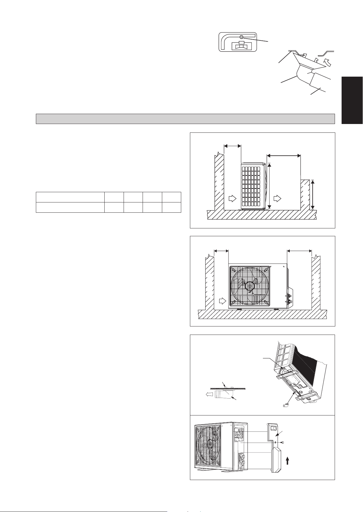
Outdoor Unit
INSTALLATION OF THE OUTDOOR UNIT (25/35)
Where a wall or other obstacle is in the path of outdoor unit’s intake or exhaust airflow, follow the installation guidelines
•
below.
For any of the below installation patterns, the wall height on the exhaust side should be 1200mm or less.
•
Wall facing one side
More than 50
More than 100
1200 or
less
Side View
Wall facing two sides
More
than 100
More than 50
Wall facing three sides
More than 150
More than 50
Top View
More than 50
1-6
More than 150
More than 300
Top View
Unit : mm
Drain work. (Heat Pump Unit Only)
1) Use drain plug for drainage.
2) If the drain port is covered by a mounting base or floor surface, place
additional foot bases of at least 30mm in height under the outdoor
unit’s feet.
3) In cold areas, do not use a drain hose with the outdoor unit. (Otherwise,
drain water may freeze, impairing heating performance.)
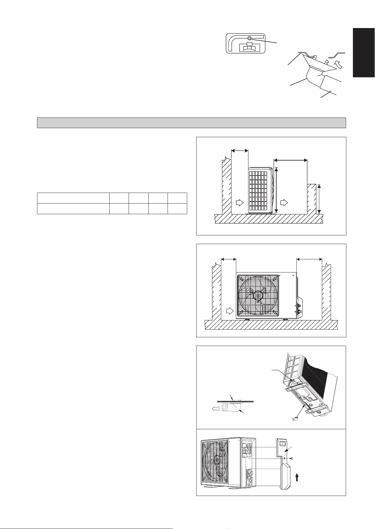
INSTALLATION OF THE OUTDOOR UNIT (50/60)
The outdoor unit must be installed in such a way, so as to
prevent short circuit of the hot discharged air or obstruction to
the smooth air flow. Please follow the installation clearances
shown in the figure. Select the coolest possible place where
intake air temperature is not greater than the outside air
temperature (Refer to operating range).
Drain water hole
Bottom frame
Drain Plug
Hose (available comercially,
inner dia. 16mm)
A
B
English
Installation clearances
Dimension
ABCD
Minimum Distance, mm 300 1000 300 500
Note: If there is any obstacle higher than half, of the unit’s
height (H), please allow more space than the figure indicated
in the above table.
Condensed Water Disposal Of Outdoor Unit
(Heat Pump Unit Only)
There are 2 holes on the base of Outdoor Unit for condensed
•
water to flow out. Insert the drain elbow to one of the
holes.
To install the drain elbow, first insert one portion of the
•
hook to the base (portion A), then pull the drain elbow in
the direction shown by the arrow while inserting the other
portion to the base. After installation, check to ensure that
the drain elbow clings to base firmly.
If the unit is installed in a snowy and chilly area, condensed
•
water may freeze in the base. In such case, please remove
plug at the bottom of unit to smooth the drainage.
Obstacle
C
Obstacle
Return air
Return air
H
Discharge air
H/2
Obstacle
D
Obstacle
Service access
1-7
PLUG
A
BASE
DRAIN ELBOW
DRAIN ELBOW
Please remove side
plate when connecting
the piping and
connecting cord
PUSH & PULL UP
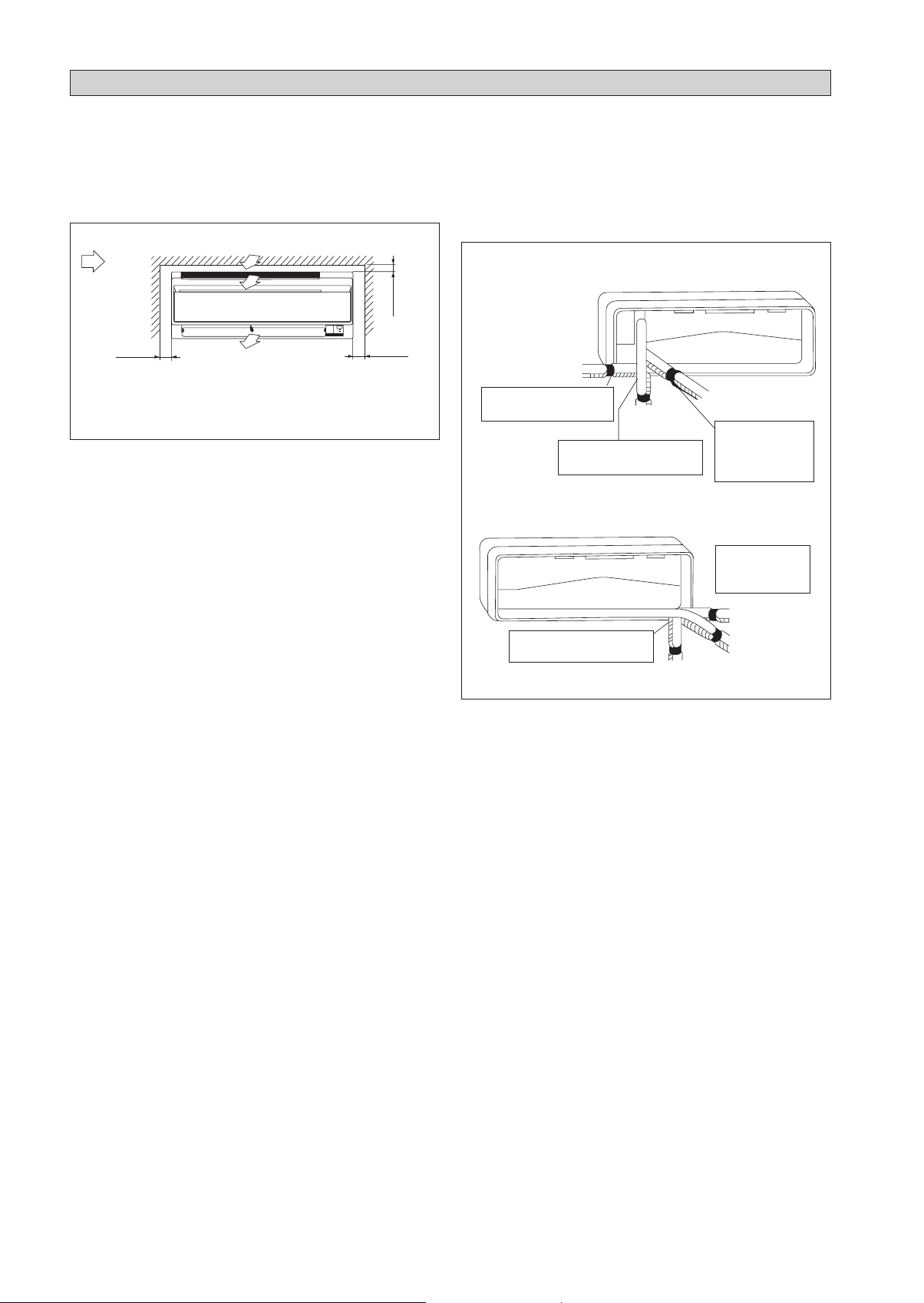
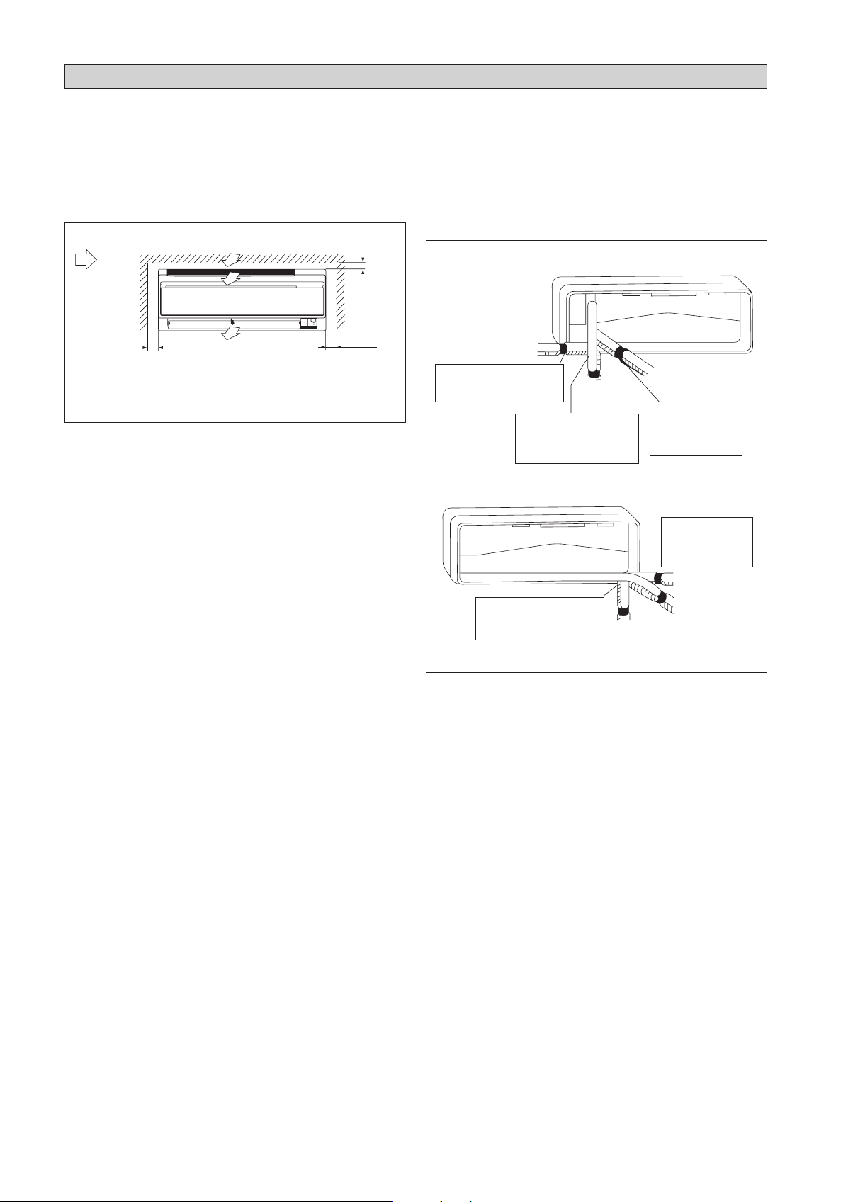
INSTALLATION OF THE INDOOR UNIT
The indoor unit must be installed in such a way so as to prevent
short circuit of the cool discharged air with the hot return air.
Please follow the installation clearance shown in the figure. Do
not place the indoor unit where there could be direct sunlight
shining on it. Also, this location must be suitable for piping
and drainage, and be away from doors or windows.
Air flow
(Indoor)
min. 75
(Space for
performance)
min. 50
(Space for
maintenance)
Required space
All dimensions are in mm
min. 50
(Space for
maintenance)
The refrigerant piping can be routed to the unit in a number
of ways (left or right from the back of the unit), by using the
cut-out holes on the casing of the unit. Bend the pipes carefully
to the required position in order to align it with the holes. For
the side and bottom out, hold the bottom of the piping and
then position it to the required direction. The condensation
drain hose can be taped to the pipes.
Right-side, right-back or right-bottom piping
Right-side piping
Remove pipe port cover
here for right-side piping
Remove pipe port cover
here for right-bottom piping
Right-bottom
piping
Right-back piping
Bind coolant pipe
and drain hose
together with
insulating tape.
Left-side, left-back or left-bottom piping
Remove pipe port
cover here for
left-side piping
Remove pipe port cover
here for left-bottom piping
Left-side piping
Left-back piping
Left-bottom piping
1-8
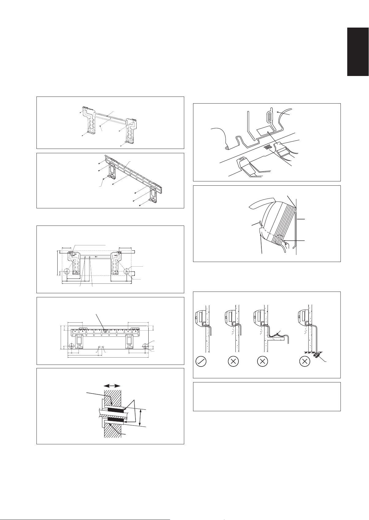
Mounting Installation Plate
Ensure that the wall is strong enough to withstand the weight
of the unit. Otherwise, it is necessary to reinforce the wall
with plates, beams or pillars.
Use the level gauge for horizontal mounting, and fix it with
5 suitable screws for FTXC 25/35 and 7 suitable screws for
FTXC 50/60.
In case the rear piping draws out, drill a hole 65mm in
diameter with a cone drill, slightly lower on the outside wall
(see figure).
FTXC 25/35
Mounting plate
Mount The Unit Onto The Installation Plate
Hook the indoor unit onto the upper portion of the installation
plate (Engage the two hooks at the rear top of the indoor unit
with the upper edge of the installation plate). Ensure that the
hooks are properly seated on the installation plate by moving
it to the left and right.
How To Attach The Indoor Unit
Hook the claws of the bottom frame to the mounting plate.
How To Remove The Indoor Unit
Push up the marked area (at the lower part of the front
grille) to release the claws.
Mounting plate
English
Mounting plate
fixing screw
FTXC 50/60
Mounting plate
Mounting plate fixing screw
Recommended Mounting Plate Retention Spots And
Dimensions
FTXC 25/35
Recommended mounting plate retention spots
«
(5 spots in all)
104
30
288
46
153
55 207
Liquid pipe end
52
800
FTXC 50/60
« Recommended mounting plate retention spots
(7 spots in all)
190
61
310
40
45
91
580
Gas pipe end
45
1065
141
30
Through the wall hole Ø 65mm
46
Drain hose position
56
181
All dimensions are in mm
173
61
Through the wall hole
Ø 65mm
40
Drain hose position
48
Gas pipe endLiquid pipe end
219
All dimensions are in mm
Clip
Front grille
Bottom frame
Mark (Rear side)
Hang indoor unit’s hook here.
When stripping the ends
of interconnecting wires in
Mounting plate
advance, bind right ends of
wires with insulating tape.
Interconnecting
wires
Wire guide
Water Drainage Piping
The indoor drain pipe must be in a downward gradient for
smooth drainage. Avoid situations that are likely to cause
water to leak.
Water Drainage
Water
Water
leaking
Water
leaking
retention
Water
leaking
End
dipped
into
water
Drain
Hole with cone drill
Inside
Wall embedded pipe
(Field supply)
Wall hole cover
(Field supply)
Outside
Caulking
Ø 65
Wall embedded pipe
(Field supply)
Correct Wrong
Wrong Wrong
! CAUTION
• Do not install the unit at altitude over 2000m for both
indoor & outdoor.
1-9
REFRIGERANT PIPING
Allowable Piping Length
If the pipe is too long, both the capacity and reliability of the unit will drop. As the number of bends increases, resistance to
the flow of refrigerant system increases, thus lowering cooling capacity. As a result, the compressor may become defective.
Always choose the shortest path and follow the recommendations as tabulated below:
Indoor Unit
LE
Outdoor Unit
Model
Indoor (FTXC) 25 35 50 60
Outdoor (RXC) 25 35 50 60
Min. Allowable Length (L), m 33
Max. Allowable Length (L), m 20 30
Max. Allowable Elevation (E), m 15 15
Gas Pipe Size, mm/(in)
Liquid Pipe Size, mm/(in)
*Be sure to add the proper amount of additional refrigerant. Failure to do so may result in reduced performance.
9.52 (3/8") 12.70 (1/2")
6.35 (1/4") 6.35 (1/4")
Remark: The refrigerant pre-charged in the outdoor unit is for piping length up to 7.5m.
Equivalent length for various fitting (meter)
Pipe Size L joint Trap bend
3/8" (OD9.52mm) 0.18 1.3
1/2" (OD12.7mm) 0.20 1.5
5/8" (OD15.9mm) 0.25 2.0
3/4" (OD19.1mm) 0.35 2.4
7/8" (OD22.2mm) 0.40 3.0
1" (OD25.4mm) 0.45 3.4
1 1/8" (OD28.6mm) 0.50 3.7
1 3/8" (OD34.9mm) 0.60 4.4
Notes:
1. Equivalent piping length is obtained with actual length of gas piping.
2. 90° bend of piping is equivalent to L joint.
Bending must be carefully made so as not to crush the pipe. Use a pipe bender to bend a pipe where possible.
1-10
REFRIGERANT PIPING
Piping Works And Flaring Technique
Do not use contaminated or damaged copper tubing. If
•
any piping, evaporator or condenser had been exposed or
had been opened for 15 seconds or more, the system must
be vacuumed. Generally do not remove plastic, rubber
plugs and brass nuts from the valves, fittings, tubing and
coils until it is ready to connect suction or liquid line into
valves or fittings.
If any brazing work is required, ensure that nitrogen gas
•
is passed through coil and joints while the brazing work
is being done. This will eliminate soot formation on the
inside wall of copper tubings.
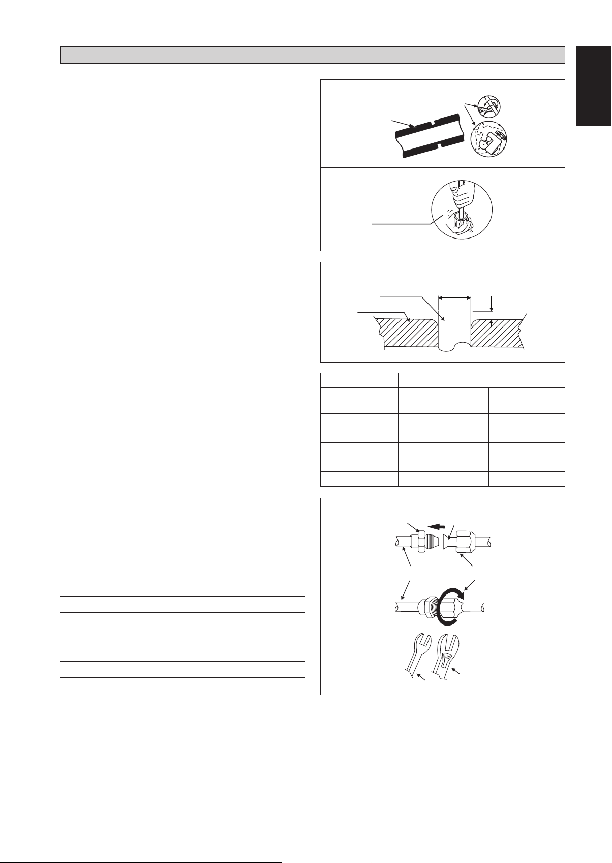
Cut the pipe stages by stages, advancing the blade of pipe
•
cutter slowly. Extra force and a deep cut will cause more
distortion of pipe and therefore extra burr. See Figure I.
Remove burrs from cut edges of the pipes with remover. See
•
Figure II. Hold the pipe on top position and burr remover
at lower position to prevent metal chips from entering the
pipe. This will avoid unevenness on the flare faces which
will cause gas leak.
Insert the flare nuts, mounted on the connection parts
•
of both the indoor unit and outdoor unit, into the copper
pipes.
The exact length of pipe protruding from the top surface
•
of the swaging block is determined by the flaring tool.
See Figure III.
Fix the pipe firmly on the swaging block. Match the centers
•
of both the swaging block and the flaring punch, then
tighten the flaring punch fully.
The refrigerant pipe connection are insulated by closed
•
cell polyurethane.
Piping Connection To The Units
Align the center of the piping and tighten the flare nut
•
sufficiently with fingers. See Figure IV.
Finally, tighten the flare nut with torque wrench until the
•
wrench clicks.
When tightening the flare nut with the torque wrench,
•
ensure that the tightening direction follows the arrow
indicated on the wrench.
The refrigerant pipe connection are insulated by closed
•
cell polyurethane.
Figure I
Figure II
Figure III
Swaging Block
Cutting Copper Tube
1/4t
Remove Burr
Copper Tube
D
A
Ø Tube, D A (mm)
Inch mm Imperial
(Wing-nut Type)
Rigid
(Clutch Type)
1/4" 6.35 1.3 0.7
3/8" 9.52 1.6 1.0
1/2" 12.70 1.9 1.3
5/8" 15.88 2.2 1.7
3/4" 19.05 2.5 2.0
Figure IV
Flare Joint
Flared Tube
Flare NutIndoor Piping
English
Pipe Size, mm (in) Torque, Nm/(ft-lb)
6.35 (1/4") 18 (13.3)
9.52 (3/8") 42 (31.0)
12.70 (1/2") 55 (40.6)
15.88 (5/8") 65 (48.0)
19.05 (3/4") 78 (57.6)
1-11
Spanner
Torque Wrench
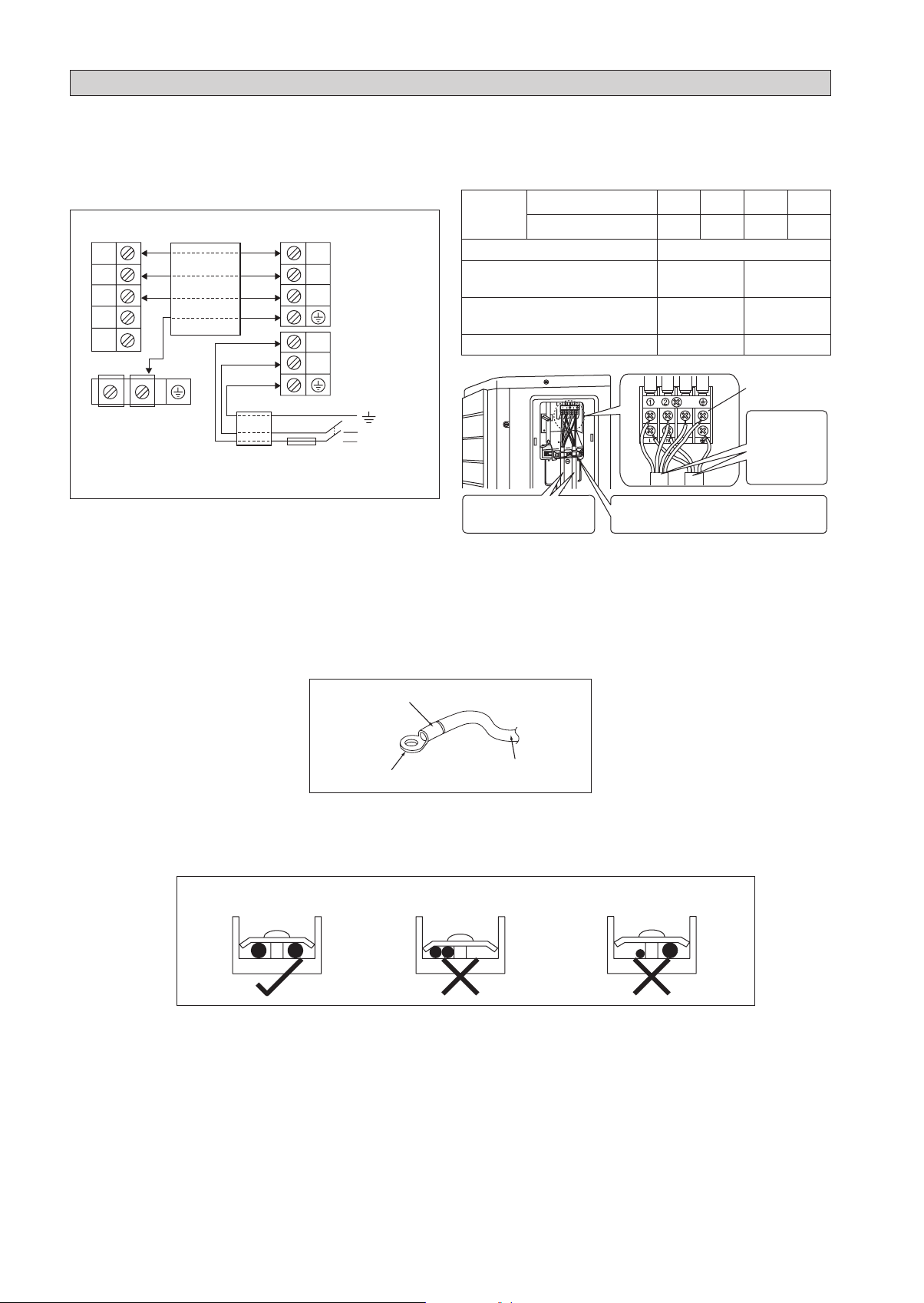
ELECTRICAL WIRING CONNECTION
IMPORTANT : * The figures shown in the table are for information purpose only. They should be checked and selected
to comply with the local/national codes of regulations. This is also subject to the type of installation and
conductors used.
** The appropriate voltage range should be checked with label data on the unit.
Inverter (Power Outdoor)
Indoor Unit
Terminal Block
1
2
SIG
There must be an all pole disconnection
!
in the supply mains with a contact
separation of at least 3mm.
All wires must be firmly connected.
•
Make sure all the wire do not touch the refrigerant pipings, compressor or any moving parts.
•
The connecting wire between the indoor unit and the outdoor unit must be clamped by using provided cord anchorage.
•
The power supply cord must be equivalent to H07RN-F which is the minimum requirement.
•
Make sure no external pressure is applied to the terminal connectors and wires.
•
Make sure all the covers are properly fixed to avoid any gap.
•
Use round crimp-style terminal for connecting wires to the power supply terminal block. Connect the wires by matching
•
Interconnection
cable
Outdoor Unit
Terminal Block
1
2
SIG
L
N
Power Supply Cable
Fuse / Circuit
Breaker
Main
Switch
N / L2
L / L1
Power
Supply
Model Indoor (FTXC)
Outdoor (RXC)
Voltage range
Power supply cable size
**
*
mm
Number of conductors
Interconnection cable size
*
mm
Number of conductors
25 35 50 60
25 35 50 60
220-240V/~/50Hz +
2
1.5
3
2
1.5
4
!
Recommended fuse /circuit breaker rating A 16 20
Power supply
terminal block
Shape wires so
that the service
lid and stop
valve cover fit
securely.
Use the specified wire type
and connect it securely.
SIG
Firmly secure wire retainer so wire
terminations will not receive external stress.
2.5
3
2.5
4
to the indication on terminal block. (Refer to the wiring diagram attached on the unit).
Attach insulation sleeve
Round crimp-style terminal
Used the correct screwdriver for terminal screws tightening. Unsuitable screwdrivers can damage the screw head.
•
Over tightening can damage the terminal screws.
•
Do not connect wire of different gauge to same terminal.
•
Keep wiring in an orderly manner. Prevent the wiring from obstructing other parts and the terminal box cover.
•
Connect wires of the
same gauge to both side.
Do not connect wires of the
same gauge to one side.
Electric wire
Do not connect wires
of different gauges.
1-12
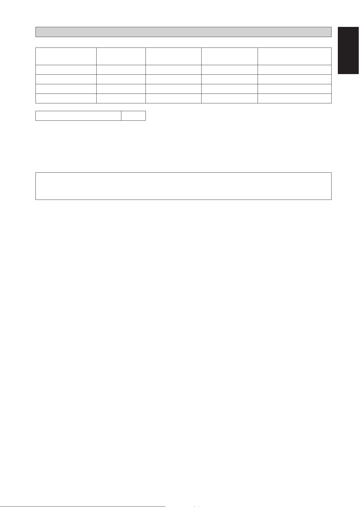
SPECIAL PRECAUTIONS WHEN DEALING WITH R32 UNIT
Model
FTXC25AV1B - RXC25AV1B 0.6 0.34 0.94 0.84
FTXC35AV1B - RXC35AV1B 0.8 0.61 1.14 1.24
FTXC50AV1B - RXC50AV1B 1.1 1.15 1.61 2.47
FTXC60AV1B - RXC60AV1B 1.2 1.37 1.71 2.79
Installation Height, h
*Max. Allowable Length (L), m for:FTXC25/35A-RXC25/35A : 20
FTXC50/60A-RXC50/60A : 30
Installation of pipe work shall be kept to a minimum and pipe work shall be protected from physical damage and shall not be
•
installed in an unventilated space;
Reusable mechanical connectors and flare joints shall be accessible for maintenance purposes;
•
(m) = 1.8
o
R32 charge, kg for 7.5m
piping
Minimum floor area, Xm2
(based on 7.5m piping)
R32 charge, kg for max
allowable pipe length*
Minimum floor area, Xm2
(based on max allowable pipe length *)
! WARNING
Prior to installation, ensure risk of ignition is minimised and avoid working in confined space. Ensure adequate
ventilation is available by opening windows or doors.
When flared joints are reused indoors,the flare part shall be re-fabricated.
•
Avoid installation of the air conditioner in a place where there is danger of exposure to continuously operating open flam
•
example an operating electric heaters).
Any person who is involved with working on or breaking into a refrigerant circuit should hold a current valid certificate from an
•
industry-accredited assessment authority, which authorises their competence to handle refrigerants safely in accordance with an
industry recognised assessment specification.
es (for
English
Checking for presence of refrigerant
•
The area shall be checked with an appropriate refrigerant detector prior to and during work, to ensure the technician is aware of
potentially flammable atmospheres. Ensure that the leak detection equipment being used is suitable for use with flammable refrigerants,
i.e. nonsparking, adequately sealed or intrinsically safe.
Presence of fire extinguisher
•
If any hot work is to be conducted on the refrigeration equipment or any associated parts, appropriate fire extinguishing equipment
shall be available to hand. Have a dry powder or CO2 fire extinguisher adjacent to the charging area.
No ignition sources
•
All possible ignition sources, including cigarette smoking, should be kept sufficiently far away from the site of installation, repairing,
removing and disposal, during which flammable refrigerant can possibly be released to the surrounding space. “No Smoking” signs
shall be displayed.
The following checks shall be applied to installations:
•
marking to the equipment continues to be visible and legible. Markings and signs that are illegible shall be corrected;
–
refrigeration pipe or components are installed in a position where they are unlikely to be exposed to any substance which may
–
corrode refrigerant containing components, unless the components are constructed of materials which are inherently resistant
to being corroded or are suitably protected against being so corroded.
1-13

Initial safety checks shall include:
•
that capacitors are discharged, this shall be done in a safe manner to avoid possibility of sparking
–
there shall be no live electrical components and wiring are exposed while charging, recovering or purging the system;
–
Repair to intrinsically safe components
•
Do not apply any permanent inductive or capacitance loads to the circuit without ensuring that this will not exceed the permissible
voltage and current permitted for the equipment in use.
Replace components only with parts specified by the manufacturer.
•
Leak detection methods
Ensure that the detector is not a potential source of ignition (for example a halide torch) and is suitable for the refrigerant
used. Leak detection equipment shall be set at a percentage of the LFL of the refrigerant (for R32, LFL is 13%) and shall be
calibrated to the refrigerant employed and the appropriate percentage of gas (25 % maximum) is confirmed.
Leak detection fluids are suitable for use with most refrigerants but the use of detergents containing chlorine shall be avoided
as the chlorine may react with the refrigerant and corrode the copper pipe-work. If a leak is suspected, all naked flames shall
be removed/extinguished. If a leakage of refrigerant is found which requires brazing, all of the refrigerant shall be recovered
from the system, or isolated (by means of shut off valves) in a part of the system remote from the leak. Oxygen free nitrogen
(OFN) shall then be purged through the system both before and during the brazing process.
•
Removal and evacuation
When breaking into the refrigerant circuit to make repairs – or for any other purpose – conventional procedures shall be used.
However, it is important that best practice is followed since flammability is a consideration. The following procedure shall
be adhered to:
remove refrigerant;
•
purge the circuit with inert gas;
•
evacuate;
•
purge again with inert gas;
•
open the circuit by cutting or brazing.
•
The refrigerant charge shall be recovered into the correct recovery cylinders. The system shall be “flushed” with OFN to render
the unit safe. This process may need to be repeated several times. Compressed air or oxygen shall not be used for this task.
Flushing shall be achieved by breaking the vacuum in the system with OFN and continuing to fill until the working pressure is
achieved, then venting to atmosphere, and finally pulling down to a vacuum. This process shall be repeated until no refrigerant
is within the system. When the final OFN charge is used, the system shall be vented down to atmospheric pressure to enable
work to take place. This operation is absolutely vital if brazing operations on the pipe-work are to take place. Ensure that the
outlet for the vacuum pump is not close to any ignition sources and there is ventilation available.
Labelling
•
This unit shall be labelled ‘de-commissioned and emptied of refrigerant’. This label shall be dated and signed. Ensure that
there are labels on the equipment stating the equipment contains flammable refrigerant.
1-14
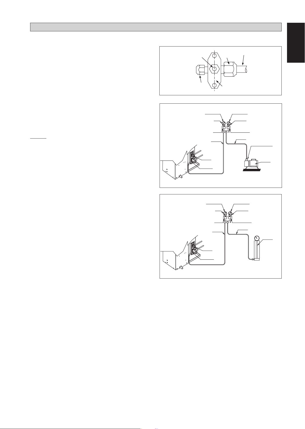
VACUUMING AND CHARGING
Vacuuming is necessary to eliminate all moisture and air from the system.
Vacuuming The Piping And The Indoor Unit
Except for the outdoor unit which is pre-charged with
refrigerant, the indoor unit and the refrigerant connection
pipes must be air-purged because the air containing moisture
that remains in the refrigerant cycle may cause malfunction
of the compressor.
Remove the caps from the valve and the service port.
•
Connect the center of the charging gauge to the vacuum
•
pump.
Connect the charging gauge to the service port of the 3-way
•
valve.
Start the vacuum pump. Evacuate for approximately 30
•
minutes. The evacuation time varies with different vacuum
pump capacity. Confirm that the charging gauge needle has
moved towards -760mmHg.
Caution
If the gauge needle does not move to -760mmHg, be sure
•
to check for leakage at flare type connection of the indoor
and outdoor unit and repair the leak before proceeding to
the next step.
Close the valve of the changing gauge and stop the vacuum
•
pump.
On the outdoor unit, open the suction valve (3 way) and
•
liquid valve (2 way) (in anti-clockwise direction) with 4mm
key for hexagon sacked screw.
Allen key
Service Port
LOW PRESSURE GAUGE
-760mmHg
HANDLE LO
CHARGE HOSE
LIQUID VALVE
GAS VALVE
(3-WAY)
Flare nut
Outdoor Unit 3 ways valve
Refrigerant Piping
HIGH PRESSURE GAUGE
GAUGE MANIFOLD
HANDLE HI (ALWAYS CLOSED)
CHARGE HOSE
VACUUM PUMP
ADAPTER FOR
COUNTER FLOW
PREVENTION
CHECK VALVE
CONFIGURATION OF AIR
PURGE BY CHARGING
English
Charge Operation
This operation must be done by using a gas cylinder and a
precise weighing machine. The additional charge is topped-up
into the outdoor unit using the suction valve via the service
port.
Remove the service port cap.
•
Connect the low pressure side of the charging gauge to the
•
suction service port center of the cylinder tank and close
the high pressure side of the gauge. Purge the air from the
service hose.
Start the air conditioner unit.
•
Open the gas cylinder and low pressure charging valve.
•
When the required refrigerant quantity is pumped into
•
the unit, close the low pressure side and the gas cylinder
valve.
Disconnect the service hose from service port. Put back
•
the service port cap.
LOW PRESSURE GAUGE
-760mmHg
HANDLE LO
CHARGE HOSE
LIQUID VALVE
GAS VALVE
(3-WAY)
HIGH PRESSURE GAUGE
GAUGE MANIFOLD
HANDLE HI (ALWAYS CLOSED)
CHARGE HOSE
CHECK VALVE
CONFIGURATION OF AIR
PURGE BY CHARGING
1-15
ADDITIONAL CHARGE
The refrigerant is pre-charged in the outdoor unit. If the piping length is less than 7.5m, then additional charge after vacuuming
is not necessary. If the piping length is more than 7.5m, then use the additional charge value as indicated in the table.
Additional refrigerant charge [g] per additional 1m length as tabulated
Model
Indoor (FTXC) 25 35 50 60
Outdoor (RXC) 25 35 50 60
Additional charge [g/m] 17 17 17 17
Example:
FTXC25 & RXC25 with 12m piping length, additional piping length is 4.5m. Thus,
Additional charge = 4.5[m] x 17[g/m]
= 76.5[g]
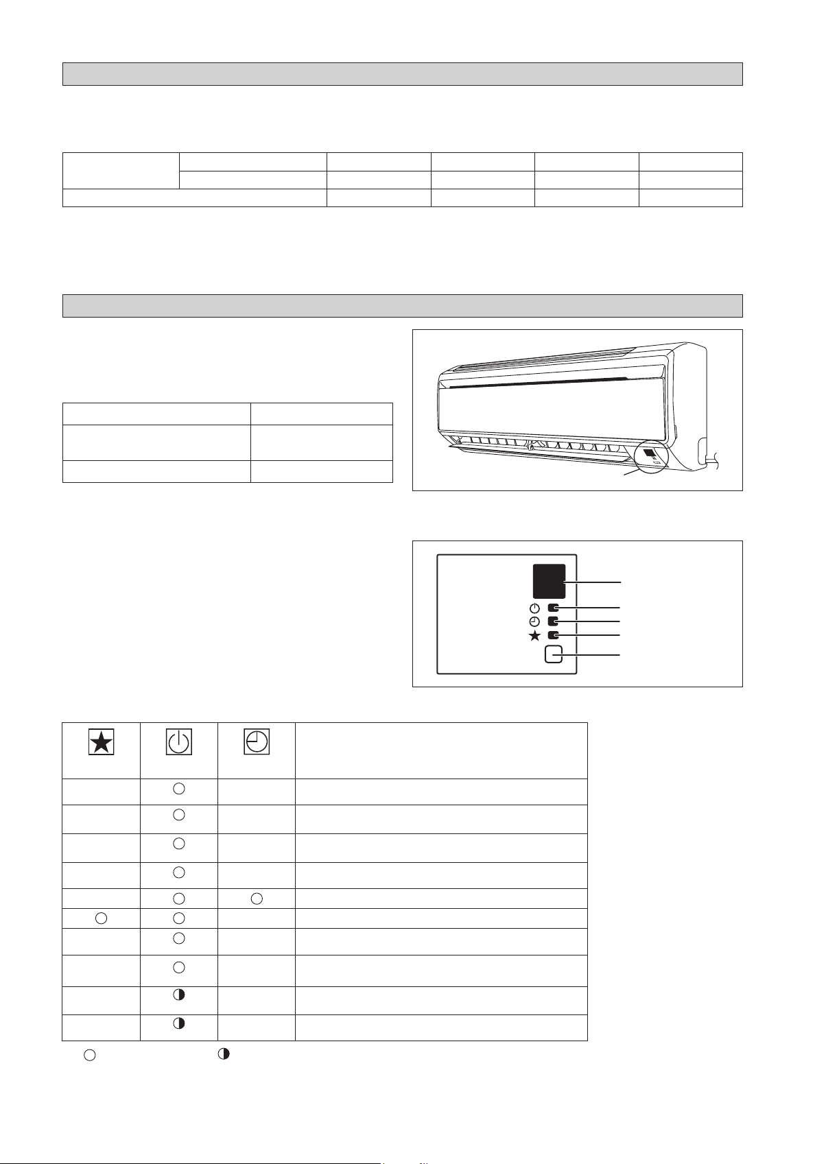
INDICATOR LIGHTS
IR Signal Receiver
When an infrared remote control operating signal has been
transmitted, the signal receiver on the indoor unit will respond
as below to confirm acceptance of the signal transmission.
ON to OFF 1 Long Beep
OFF to ON
Pump down / Cool force on
Others 1 Short Beep
Cooling Unit/Heat Pump Unit
The table shows the LED indicator lights for the air conditioner
unit under normal operation and fault conditions. The LED
indicator lights are located at the side of the air conditioner
unit.
The heat pump units are equipped with an “auto” mode
sensor whereby it will provide reasonable room temperature
by switching automatically to either “cool” or “heat” mode
according to the temperature set by the user.
2 Short Beep
IR Receiver
LED Indicator Lights for Cooling Unit/Heat Pump
Unit
IR Receiver
Cool/Heat
Timer
Sleep
ON/OFF
ON/OFF switch
LED Indicator Lights: Normal Operation And Fault Conditions For Cooling/Heat Pump Unit
Operation
Cool mode
Heat mode
Auto mode in Heating operation
Auto mode in Cooling operation
Timer on
Sleep mode on
Fan mode on
Dry mode on
Defrost operation
Unit error
ON
COOL/HEAT
(BLUE/RED)
BLUE
RED
RED
BLUE
BLUE
BLUE
RED
BLUE
Blinking
1-16

Heat Pump Model
OPERATING RANGE
Model: FTXC 25/35 RXC 25/35
COOLING HEATING
50
46
43
40
30
20
10
OUTDOOR TEMP (˚CDB)
0
INDOOR TEMP (˚CWB)
Model: FTXC 50/60 RXC 50/60
50
46
43
40
30
20
10
COOLING HEATING
252314 15 19 2010
DB: Dry bulb WB: Wet bulb
20
18
10
0
-10
-15
OUTDOOR TEMP (˚CWB)
-20
20
18
10
0
English
2015 03725201
INDOOR TEMP (˚CDB)
0
-10
OUTDOOR TEMP (˚CDB)
-20
10 14 15 19 20 23 25
INDOOR TEMP (˚CWB)
-10
-15
OUTDOOR TEMP (˚CWB)
-20
DB: Dry bulb WB: Wet bulb
2015 03725201
INDOOR TEMP (˚CDB)
1-17
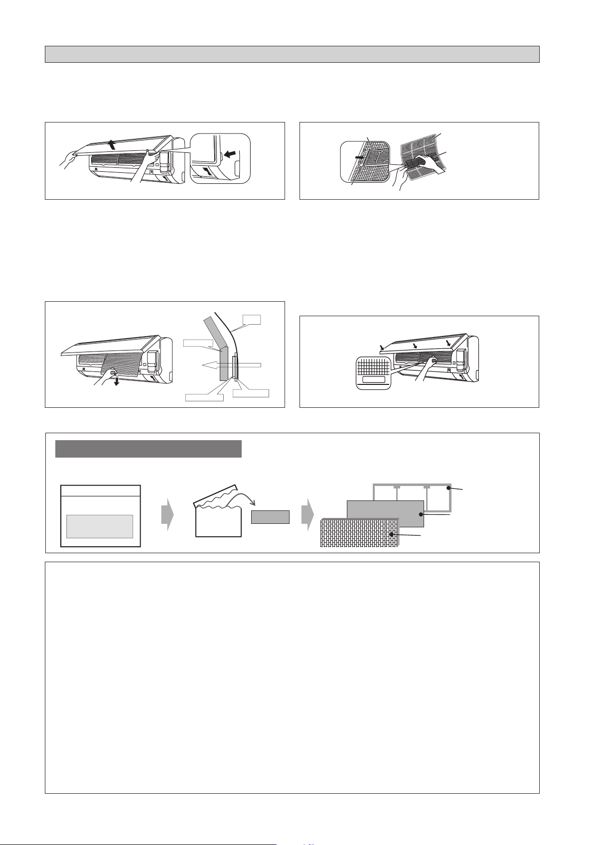
AIR FILTER
1. Open the front panel.
• Hold the panel at the recesses on the main unit
(2 recesses on right and left sides) and lift it until it
stops.
Recess on
main unit
2. Pull out the air filters.
• Push a little upwards the tab at the center of each air
filter, then pull it down.
3. Take off the Bio filter with bacteriostatic,
virustatic functions.
• Hold the recessed parts of the frame and unhook the
four claws.
Titanium Apatite Filter (Bio Filter)
Attached Concept
Heat exchanger
Air Filter
4. Clean or replace each filter.
See figure.
• When shaking off remaining water, do not wring the
filter.
Filter frame
Tab
Air filter
Bio filter with
bacteriostatic,
virustatic functions
5. Set the air filter and Bio filter with bacteriostatic,
virustatic functions as they were and close the
front panel.
• Insert claws of the filters into slots of the front panel.
Close the front panel slowly and push the panel at the
3 points. (1 on each side and 1 in the middle.)
• The air filter and Bio filter with bacteriostatic,
virustatic functions have a symmetrical form in the
horizontal direction.
FRONT
Bio Filter attached part
Titanium Apatite Filter
* Bio Filter and Titanium Apatite Filter are optional accessories.
Installation Procedure for Bio Filter
Bio Filter packs in a
hermetically-sealed bag.
Take it out
at the time of installation.
Slip the Filter in between Filter frame and
Titanium Apatite Filter.
Filter frame
Bio Filter
Titanium Apatite Filter
! CAUTION
• Please use this Bio Filter during dry season such as winter.
• Storage, handling and disposal methods.
• The lifetime of this Bio Filter is about a year after opening.
• In case you do not use this Bio Filter right away, please don’t place the Bio Filter in any place where it will be
subjected to direct sunlight, high temperatures and/or high humidity.
• There can be slight differences between Bio Filter color because of the manufacturing reasons, there is no effect
on the unit performance.
• Please open this bag right before you use it. Bio Filter should remain unopened and sealed in its packaging until
right before usage. (It may cause performance deterioration or quality change.)
• To avoid danger of suffocation and any unexpected accident, please dispose the plastic bag immediately after you
remove the Bio Filter. Keep out of reach of babies and children.
• If you keep this Bio Filter for a long time, please keep it unopened and store in a cool place avoiding direct
sunlight.
• Please dispose the old Bio Filter as nonflammable garbage after use.
• Operation with dirty filters:
(1) cannot deodorize the air. (3) results in poor heating or cooling.
(2) cannot clean the air. (4) may cause odour.
• To order Bio Filter, contact the service shop where you bought the air conditioner.
1-18
SERVICE AND MAINTENANCE
Service Parts Maintenance Procedures Period
Indoor air filter Remove any dust adhering to the filter by using a vacuum cleaner or wash
1.
in lukewarm water (below 40°C/104°F) with a neutral cleaning detergent.
Rinse the filter well and dry before placing it back onto the unit.
2.
Do not use gasoline, volatile substances or chemicals to clean the filter.
3.
At least once every
2 weeks.
More frequently if
necessary.
English
Indoor unit Clean any dirt or dust on the grille or panel by wiping it with a soft cloth
1.
soaked in lukewarm water (below 40°C/104°F) and a neutral detergent
solution.
Do not use gasoline, volatile substances or chemicals to clean the indoor
2.
unit.
At least once every
2 weeks.
More frequently if
necessary.
! CAUTION
• Avoid direct contact of any coil treatment cleaners on plastic part. This may cause plastic part to deform as a result
of chemical reaction.
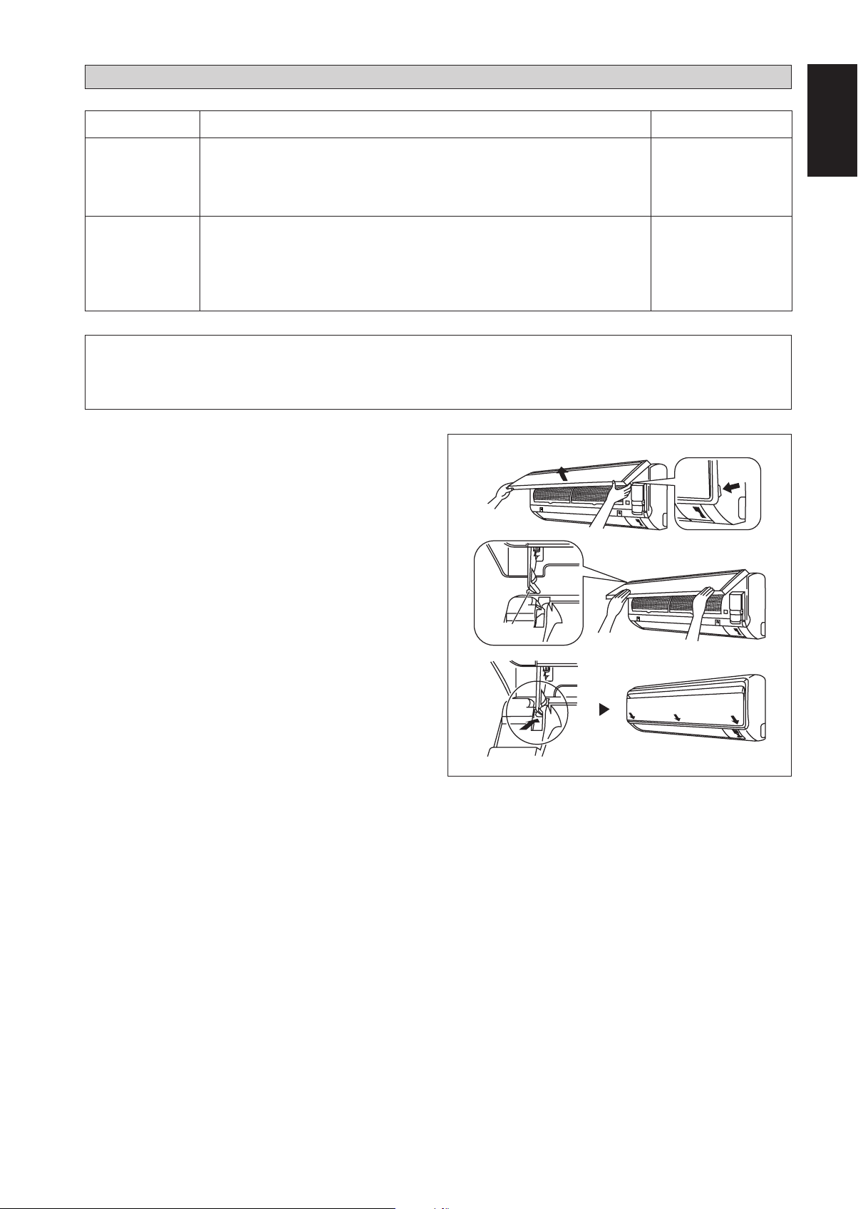
Open the front panel.
1.
Hold the panel at the recesses on the main unit
•
(2 recesses on right and left sides) and lift it until it
stops.
Remove the front panel.
2.
While lifting the front panel further, slide it to the right
•
and pull it to the front side. The left rotating shaft is
detached. Slide the right rotating shaft to the left and
pull it to the front side to remove it.
Attach the front panel.
3.
Align the right and left rotating shafts of the front panel
•
with the grooves and push them all the way in.
Gently close the front panel. (Push both ends and the
•
center on the front panel.)
Rotating
shaft
Recess on
main unit
1-19
! CAUTION
•
Don’t touch the metal parts of the indoor unit. It may cause an injury.
•
When removing or attaching the front panel, support the panel securely with hand to prevent it from falling.
For cleaning, do not use hot water above 40°C, benzine, gasoline, thinner, nor other volatile oils, polishing
•
compound, scrubbing brushes, nor other hand stuff.
After cleaning, make sure that the front panel is securely fixed.
•
When The Unit Is Not To Be Used For An Extended Long Period Of Time
Operate the unit for 2 hours with
the following setting.
Operating mode : cool
Temperature : 30°C/86°F
Remove the power plug.
If you are using an
independent electric
circuit for your unit, cut
off the circuit.
Remove the batteries in
the remote control.
TROUBLESHOOTING
For any enquiries on spare part, please contact your authorized dealer. When any malfunction of the air
conditioner unit is noted, immediately switch off the power supply to the unit. Check the following fault
conditions and causes for some simple troubleshooting tips.
Fault Causes / Action
The compressor does not operate 3 minutes after the air
1. Protection against frequent starting. Wait for 3 to 4 minutes
conditioner unit is started.
The air conditioner unit does not operate.2. Power failure, or the fuse needs to be replaced.
–
for the compressor to start operating.
–
The power plug is disconnected.
–
It is possible that your delay timer has been set
–
incorrectly.
If the fault persist after all these verifications, please
–
contact the air conditioner unit installer.
The air flow is too low.3. The air filter is dirty.
Discharge air flow has bad odour.4. Odours may be caused by cigarettes, smoke particles,
Condensation on the front air grille of the indoor unit.5. This is caused by air humidity after an extended long
Water flowing out from the air conditioner unit.6. Switch off unit and call dealer.–
–
The doors or windows are open.
–
The air suction and discharge are clogged.
–
The regulated temperature is not high enough.
–
–
perfume etc. which might have adhered onto the coil.
–
period of operation.
The set temperature is too low, increase the temperature
–
setting and operate the unit at high fan speed.
If the fault persists, please call your local dealer / serviceman.
1-20
DISEGNI E DIMENSIONIS
Unità Interna [FTXC]
IL SEGNO MOSTRA LA DIREZIONE DEI TUBI
DIETRO DIETRO DESTRASINISTRA
Italiano
VISTA DALL’ALTO
A
IN BASSO IN BASSO
FERITOIA DI
AERAZIONE
VITI INSERITE NELLA
GRIGLIA FRONTALE
(ALL’INTERNO)
VISTA FRONTALE
B
RICEVITORE DI
SEGNALE
GERÄT FÜR IM HAUS
AN/ AUS-SCHALTER
TEMPERATURA
AMBIENTE TERMOSTATO
(ALL'INTERNO)
C
VISTA LATERALE
N. DI SERIE
ADESIVO
MORSETTIERA
CONTERMINALE A
TERRA
Traduzione delle istruzioni originali
2-1

Unità Interna [FTXC]
D
« Punti di ritenzione raccomandati per la piastra di montaggio
(5 punti in tutto)
E
F
B
G
JH
ML
A
Estremità del tubo del gasEstremità del tubo del liquido
F
Foro nel muro di Ø 65mm
G
Posizione del tubo di scarico
IK
Tutte le dimensioni sono in mm
Dimensioni
Modello
ABCDE FGHI JKLM
25/35 859 288 209 104 141 30 46 55 56 153 181 207 52
Unità Interna [FTXC]
« Punti di ritenzione raccomandati per la piastra di montaggio
(7 punti in tutto)
D
F
B
G
H
Estremità del tubo del liquido
J
L
Estremità del tubo del gas
M
A
E
F
Foro nel muro di Ø 65mm
G
K
I
Posizione del tubo
di scarico
Tutte le dimensioni sono in mm
Dimensioni
Modello
ABCDE FGHI JKLM
50/60 1124 310 237 190 173 61 40 45 48 91 219 580 45
2-2
Unità Esterna [RXC]
Modello
Dimensioni
EF
2,0
J
G
A
HI
N
Q
B
CD
ABCDE FGHI JKLMNOPQ
Tutte le dimensioni sono in mm
OP
KL
M
25/35 550 658 51 11 273 16 14 470 96 93 94 60 14 133 8 10 299
Unità Esterna [RXC]
Italiano
3,0
KLL
N
M
Q
A
O
V
B
P
D
U
N
S
R
Tutte le dimensioni sono in mm
C
T
GH
I
J
F
E
Dimensioni
Modello
ABCDE FGHI JKLMNO
50 855 628 328 520 179 46 93 149 101 113 603 126 164 15 34
60 855 730 328 520 179 46 93 149 101 113 603 126 164 15 34
Dimensioni
Modello
PQRS TUV
50 23 362 73 75 8 67 7
60 23 362 73 75 8 67 7
2-3
MANUALE D’INSTALLAZIONE
Il presente manuale descrive come procedere all’installazione del condizionatore per assicurarne il corretto funzionamento in condizioni di sicurezza.
Degli adattamenti possono rivelarsi necessari per rispondere a particolari esigenze locali.
Prima di utilizzare il condizionatore, leggere attentamente le presenti istruzioni. Conservarle per ogni evenienza futura.
Questo apparecchio è destinato all’uso da parte di persone esperte o formate in negozi, nell’industria leggera o in aziende agricola o all’uso commerciale
da parte di persone non addette.
Il presente apparecchio non è destinato all’uso da parte di persone, inclusi bambini, con ridotte capacità fisiche, sensoriali o mentali, o senza la dovuta
esperienza e conoscenza, a meno che non vengano poste sotto la supervisione di una persona responsabile della loro sicurezza o che tale persona fornisca
loro le istruzioni per l’uso dell’apparecchio.
Tenere i bambini sotto la supervisione di un adulto per evitare che giochino con l’apparecchio.
NORME DI SICUREZZA
! AVVERTENZA ! CAUTELA
L’installazione e la manutenzione devono essere eseguite da personale
•
qualificato, competente in questo genere di apparecchi e al corrente delle
leggi e regolamenti in vigore.
Tutti gli allacciamenti elettrici devono essere eseguiti conformemente alla
•
regolamentazione elettrica in vigore.
Prima di procedere agli allacciamenti secondo lo schema elettrico presentato
•
più avanti, accertarsi che il voltaggio dell’apparecchio corrisponda a quello
della rete.
Dotare il condizionatore di una presa di TERRA al fine di prevenire i rischi
•
originati da eventuali deficienze del sistema di isolamento.
I fili elettrici non devono toccare né i condotti dell’acqua, né gli organi
•
rotanti dei motori del ventilatore.
Prima di installare il condizionatore o di procedere ad interventi di
•
manutenzione, accertarsi che sia spento (OFF).
Togliete sempre la corrente prima di effettuare la manutenzione del
•
condizionatore.
NON rimuovere il cavo di alimentazione quando il condizionatore è acceso.
•
Questo può causare seri shock elettrici e pericolo d’incendio.
Mantenere l’unità interna e quella esterna, il cavo di alimentazione e il
•
cablaggio di trasmissione ad almeno 1m di distanza da TV e radio, per
evitare immagini distorte e scariche statiche. {A seconda del tipo e sorgente
di onde elettriche, si possono sentire scariche statiche anche a più di 1m
di distanza}.
AVVERTENZA
Non utilizzare mezzi per accelerare il processo di sbrinamento (ove applicabile)
o per la pulizia diversi da quelli consigliati dal produttore. L’apparecchio deve
essere conservato in un ambiente privo di fonti di combustione in funzionamento
continuo (ad esempio fiamme libere, apparecchi a gas in funzione o riscaldatori
elettrici in funzionamento). Non perforare né bruciare. I refrigeranti potrebbero
non contenere odore. L’apparecchio deve essere installato, azionato e conservato
in un ambiente con un’area del pavimento superiore a Xm
pagina 13).
NOTA: Il produttore può fornire altri esempi adeguati o ulteriori informazioni
sull’odore del refrigerante.
2
(riferirsi alla
Durante l’installazione, verificare accuratamente i punti seguenti.
Non procedere all’installazione in luoghi dove possano verificarsi fughe
•
di gas.
Pericolo d’incendio in caso di fughe o di concentrazioni di gas intorno
al condizionatore.
Verificare che i condotti di drenaggio siano stati correttamente
•
installati.
Un’installazione incorretta può causare delle perdite d’acqua e
danneggiare il mobilio.
•
Non sovraccaricare il condizionatore.
L’apparecchio è precaricato in fabbrica.
Qualsiasi sovraccarico provoca una sovracorrente e può danneggiare
•
Una difettosa chiusura del pannello è causa di rumori durante il
•
•
•
•
•
•
•
•
•
•
•
il compressore.
Dopo l’installazione o gli interventi di manutenzione accertarsi di
rimettere a posto il pannello di chiusura.
funzionamento.
I bordi affilati e le superfici della serpentina sono possibili aree che
possono causare pericolo di lesioni. Evitare di entrare in contatto con
tali aree.
Prima di spegnere l’apparecchio, impostare l’interruttore ON/OFF
del telecomando sulla posizione “OFF” in modo da evitare l’apertura
nociva dell’unità. In caso contrario, le ventole dell’unità iniziano a ruotare
automaticamente quando si riaccende l’apparecchio, causando pericoli di
lesioni al personale di servizio ed agli utenti.
Non installare le unità sul vano della porta o nelle sue vicinanze.
Non mettere in funzione apparecchi per il riscaldamento troppo vicini
al condizionatore d’aria o non utilizzare l’unità in un ambiente in cui
sono presenti olio minerale o vapori da olio, ciò potrebbe provocare la
fusione o la deformazione della plastica a seguito del calore eccessivo o
di una reazione chimica.
Quando l’unità è utilizzata in cucina, tenere la farina lontana in modo
da evitare che l’unità la aspiri.
Questa unità non è idonea all’utilizzo in stabilimenti dove sono presenti
nebbie di olio da taglio o polveri metalliche o dove c’è una forte
oscillazione di tensione.
Non installare le unità in aree quali le sorgenti calde o le raffinerie
petrolifere in cui è presente gas solforoso.
Accertarsi che i colori dei fili dell’unità esterna corrispondano ai
contrassegni dei morsetti dell’unità interna.
IMPORTANTE: NON INSTALLARE O UTILIZZARE IL
CONDIZIONATORE D’ARIA IN UNA ZONA LAVANDERIA.
Non usare fili congiunti e intrecciati per l’alimentazione in ingresso.
L’apparecchio non è destinato all’uso in un ambiente potenzialmente
esplosivo.
Specifiche di smaltimento
AVVISO
Il climatizzatore è contrassegnato con questo simbolo, Ciò significa che i prodotti elettrici ed elettronici non possono essere smaltiti insieme ai rifiuti
domestici non differenziati.
Non cercare di demolire il sistema da soli: la demolizione del sistema di condizionamento, nonché il recupero del refrigerante, dell’olio e di qualsiasi
altra parte devono essere eseguiti da un installatore qualificato in conformità alla legislazione locale e nazionale vigente in materia.
I climatizzatori devono essere trattati presso una struttura specializzata nel riutilizzo, riciclaggio e recupero dei materiali. Il corretto smaltimento del prodotto
eviterà le possibili conseguenze negative all’ambiente e alla salute dell’uomo. Per maggiori informazioni contattare l’installatore o le autorità locali.
Le batterie devono essere tolte dal telecomando e smaltite separatamente conformemente alla legislazione locale e nazionale vigente in materia.
2-4
IMPORTANTE
Informazioni importanti sul refrigerante utilizzato
Questo prodotto contiene gas fluorurati ad effetto serra.
Non liberare tali gas nell’atmosfera.
Tipo di refrigerante: R32
Valore GWP
(1)
GWP = Global Warming Potential (Potenziale Di Riscaldamento Globale)
Compilare con inchiostro indelebile,
1
1 la carica di refrigerante di fabbrica del prodotto,
¢
2 la quantità di refrigerante aggiuntiva nel campo e
¢
1 + 2 la carica di refrigerante totale
¢
sull’etichetta di carica del refrigerante fornita con il prodotto.
L’etichetta compilata deve essere collocata in prossimità della porta di carica del prodotto (ad esempio, all’interno del coperchio
di ispezione).
(1)
: 675
Contains fluorinated greenhouse gases
=
R32
GWP: 675
2
1
=
2
1
1
2
+
=
GWP × kg
=
1000
kg
kg
kg
tCO2eq
Italiano
Carica di refrigerante effettuata allo stabilimento: vedere la targa dati dell'unità
a
Quantità di refrigerante aggiuntiva caricata
b
Carica totale di refrigerante
c
Emissioni di gas a effetto serra della carica totale di refrigerante espressa in tonnellate di CO2 equivalente
d
GWP = potenziale di riscaldamento globale
e
NOTA
In Europa, si usano le emissioni di gas a effetto serra della carica totale di refrigerante nel sistema (espressa in
tonnellate di CO2 equivalente) per determinare gli intervalli di manutenzione. Seguire la legislazione vigente.
Formula per calcolare le emissioni di gas a effetto serra:
valore GWP del refrigerante × carica totale di refrigerante [in kg] / 1000
Applicare l'etichetta all'interno dell'unità esterna. È disponibile una posizione dedicata all'etichetta dello
2
schema dell'impianto elettrico.
2-5
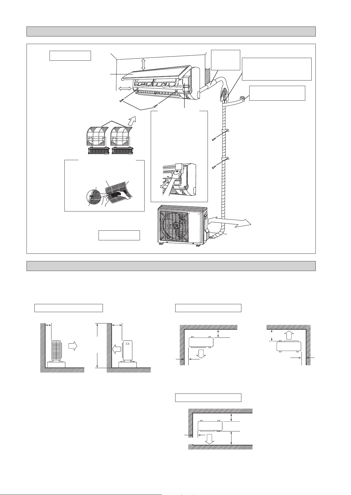
DIAGRAMMA PER L’INSTALLAZIONE
Unità Interna
Pannello anteriore
50mm o più dalle pareti
(su entrambi i lati)
Filtro depuratore dell’aria
fotocatalitico di apatite e titanio (2)
Filtro depuratore dell’aria
fotocatalitico di apatite e titanio
Telaio del filtro
Linguetta
Filtro aria
M4 x 12L
Filtro aria
75mm o più dal soffitto
Sportellino di manutenzione
Apertura del coperchio di servizio
¢
Il coperchio di servizio può essere
aperto/chiuso.
Metodo di apertura
¢
1) Rimuovere le viti del coperchio
di servizio.
2) Estrarre il coperchio di accesso
per assistenza tecnica spostandolo
verso il basso e in diagonale, nella
direzione della freccia.
3) Tirare verso il basso.
Stuccare lo
spazio del foro
del tubocon
stucco da legno.
500mm dalla parete
Tagliare il tubo di isolamento termico a
una lunghezza appropriata e avvolgerlo
con nastro, accertandosi che non ci siano
buchi nella linea di taglio del tubo di
isolamento.
Avvolgere il tubo di isolamento
da cima a fondo con nastro di
finitura.
Unità Esterna
INSTALLAZIONE DELL’UNITÀ ESTERNA (25/35)
Se c’è una parete o un altro ostacolo nel percorso dell’ingresso dell’aria dell’unità esterna o nell’uscita dell’aria di scarico,
•
seguire le linee guida per l’installazione sotto.
Per i moduli di installazione di cui sotto, l’altezza della parete sul lato di scarico dovrebbe essere pari o inferiore a
•
1200mm.
Un lato rivolto alla parete
Oltre 50
1200 o
di meno
Vista laterale
Oltre 100
Due lati rivolti alla parete
Oltre 100
Oltre 50
Tre lati rivolti alla parete
Oltre 150
Oltre 50
Vista superiore
2-6
Oltre 50
Oltre 150
Oltre 300
Vista superiore
Unità: mm
Lavoro di drenaggio. (Solo Per Le Versioni In Pompa Di Calore)
Usare il maschio di spurgo per il drenaggio.
1)
Se la bocchetta di drenaggio è coperta da una base di montaggio o dal
2)
pavimento, posizionare ulteriori piedini ad almeno 30mm d’altezza sotto
le basi dell’unità esterna.
Nelle aree fredde, non usare un tubo flessibile di scarico con l’unità
3)
esterna. (Altrimenti, l’acqua di scarico potrebbe congelarsi, danneggiando
le prestazioni di riscaldamento.)
INSTALLAZIONE DELL’UNITÀ ESTERNA (50/60)
Foro acqua di drenaggio
Struttura in basso
Maschio di spurgo
Tubo flessibile (disponibile in commercio,
diam. interno 16mm)
Italiano
L’unità esterna deve essere installata in modo tale da prevenire
ostruzioni al normale deflusso dell’aria e che la circolazione
dell’aria di scarico sia la più ampia possibile. Rispettare,
nell’installazione le distanze di sicurezza sotto indicate.
Selezionare il luogo più freddo possibile in cui la temperatura
dell’aria immessa non sia superiore alla temperatura dell’aria
esterna (Fare riferimento alla gamma operativa).
Distanze di rispetto/sicurezza
Dimensioni
ABCD
Distanza minima, mm 300 1000 300 500
Nota: Se non vi è alcun ostacolo superiore alla metà, di altezza
dell’unità (H), permetta prego più spazio rispetto al dato indicato
in tabella.
Eliminazione Acqua Di Condensa Dell’Unità Esterna
(Solo Per Le Versioni In Pompa Di Calore)
Ci sono 2 fori alla base dell’unità esterna per garantire
•
la fuoriuscita dell’acqua. Inserire il raccordo a gomito in
uno del 2 fori.
Per installare il raccordo a gomito, effettuare le seguenti
•
operazioni: prima inserire una parte del raccordo all’interno
del foro (Parte A). Quindi tirare che tra la tubazione e la
base dell’unità ci sia una fondare saldamente. Assicorarsi
che tra la tubazione e la base dell’unità ci sia una perfetta
aderenza.
Se l’unità esterna è installata in amblenti rolto freddi,
•
l’acqua di condensa potrebbe gecare du’interno della base.
Per evitario, rimuovere il tappo presente nella base per
facilitare il deflusso dell’acqua.
Ostacolo
C
Ostacolo
Aria di ritorno
A
Aria Di Ritorno
B
H
Aria Di Scarico
H/2
Ostacolo
D
Ostacolo
Pannello Di Servizio
2-7
TAP PO
A
BASE
RACCORDO A GOMITO
RACCORDO A GOMITO
Rimuovere la
copertura laterale
per effettuare i
collegamenti elettrici e
frigoriferi
SPINGERE E TIRARE
VERSO L’ALTO
INSTALLAZIONE DELL’UNITÀ INTERNA
L’unità interna deve essere installata in modo tale da evitare
corto circuito l’aria fredda scaricata con l’aria calda di ritorno.
Si prega di seguire il gioco installazione mostrata in figura.
Installare l’unità interna in modo che non si trovi ad ess ere
direttamente esposta ai raggi del sole o in prossimità di porte
e finestre. Questa disposizione è la migliore anche per le
tubazioni e il sistema di drenaggio.
Flusso d’aria
(All’interno)
min. 75
(Spazio per le
prestazioni)
min. 50
(Spazio per la
manutenzione)
Spazio necessario
Tutte le dimensioni sono in mm
min. 50
(Spazio per la
manutenzione)
Le tubazioni del refrigerante possono essere collegate
in differenti modi (lato posteriore destro o sinistro)
utilizzando i fori predisposti sul rivestimento esterno.
Piegare accuratamente i tubi nel verso richiesto per condurli al
foro appropriato. Per far fuoriuscire il lato e la parte posteriore,
tenere il fondo del tubo e posizionarlo nella direzione richiesta.
Utilizzado del nastro adesivo, fissarve quindi insieme il tubo
di drenaggio.
Tubo laterale destro, posteriore destro o in basso a destra
Tubazione sul lato destro
Rimuovere il coperchio dell’attacco
del tubo in questo punto, in caso di
tubazione sul lato destro
Rimuovere il coperchio
dell’attacco del tubo in questo
punto, in caso di tubazione sul lato
destro inferiore
Tubazione sul
latodestro inferiore
Tubazione sul lato destro
posteriore
Legare insieme il tubo di
raffreddamento e il tubo
flessibile di scarico con
nastro isolante.
Tubo laterale sinistro, posteriore sinistro o in basso a
sinistra
Rimuovere il coperchio
dell’attacco del tubo in
questo punto, in caso di
tubazione sul lato sinistro
Tubazione sul lato
Rimuovere il coperchio dell’attacco
del tubo in questo punto, in caso di
tubazione sul lato sinistro inferiore
Tubazione sul lato sinistro inferiore
sinistro
Tubazione sul lato
sinistro posteriore
2-8
 Loading...