

Daikin RY30PEV1K, RY42PEY1K, R24PEV1K, R36PEY1K, R42PEY1K Service Manual
...
SiK401004_A
Duct type
[Applied Models]
Non-Inverter Pair : Cooling Only
Non-Inverter Pair : Heat Pump

SiK401004_A
Non-Inverter Pair
Duct Type
1 INTRODUCTION....................................................................................... i
Part 1 SPECIFICATIONS............................................................1
1. MODELS LIST..........................................................................................2
1.1 Outdoor Unit.............................................................................................2
1.2 Indoor Unit................................................................................................3
2. NOMENCLATURE....................................................................................4
3. FUNCTION...............................................................................................5
4. PRODUCT DATA......................................................................................6
4.1 Product Data at Rated Condition..............................................................6
4.2 Electrical Data ........................................................................................27
5. PIPING DIAGRAM..................................................................................28
Part 2 FUNCTION CONTROL ...................................................... 29
1. OPERATION FLOWCHART...................................................................30
1.1 Cooling/Dry Operation............................................................................30
1.2 Heating Operation ..................................................................................31
2. MAIN LOGIC ..........................................................................................32
2.1 Cooling Mode .........................................................................................32
2.2 Dry Mode................................................................................................33
2.3 Heating Mode.........................................................................................34
2.4 Defrosting...............................................................................................35
2.5 Fan Mode ...............................................................................................36
3. WIRED REMOTE CONTROLLER..........................................................37
3.1 Displaying Part .......................................................................................38
3.2 Buttons...................................................................................................39
3.3 Installation of Wired Controller and Project Debugging..........................41
3.4 Instruction to Operation..........................................................................43
3.5 Error Display...........................................................................................56
3.6 Setting of Indoor Room Sensor and Checking of Outdoor Ambient
Temperature...........................................................................................57
Part 3 INSTALLATION ................................................................ 60
1. INDOOR UNIT INSTALLATION..............................................................61
1.1 Installation of Duct Type.........................................................................61
2. OUTDOOR UNIT INSTALLATION..........................................................69
2.1 Before Installation...................................................................................69
2.2 Installation Site.......................................................................................69
2.3 Cautions for Installation..........................................................................70
2.4 Dimension Data......................................................................................71
2.5 Installation Clearance Data ....................................................................72
3. REFRIGERATION PIPING WORK.........................................................73
3.1 Refrigeration Piping Work Procedures...................................................73
3.2 Caution in Connecting Pipes..................................................................78

SiK401004_A
3.3 Specification of Connection Pipe............................................................79
4. ELECTRIC WIRING WORK ...................................................................80
4.1 Wiring Principle ......................................................................................80
4.2 Electric Wiring Design............................................................................84
4.3 Specification of Power Supply Wire and Air Switch................................86
Part 4 MAINTENANCE ................................................................ 87
1. REMOTE CONTROLLER DISPLAY MALFUNCTION AND CONTENTS ..88
2. FLOW CHART OF TROUBLESHOOTING.............................................91
3 WIRING DIADRAM...............................................................................101
3.1 Wiring Diagram-Outdoor Units .............................................................101
3.2 Wiring Diagram-Indoor units.................................................................109
4. DISASSEMBLY AND ASSEMBLY PROCEDURE OF MAIN PARTS.... 110
4.1 Outdoor Unit.........................................................................................110
4.2 Indoor Unit............................................................................................119
SiK401004_A
INTRODUCTION i
1. INTRODUCTION
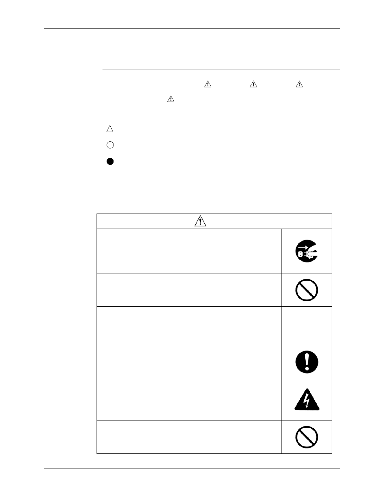
1.1 Safety Cautions
Cautions and
Warnings
Be sure to read the following safety cautions before conducting repair work.
The caution items are classified into “
Warning” and “ Caution”. The “ Warning”
items are especially important since they can lead to death or serious injury if they are not
followed closely. The “
Caution” items can also lead to serious accidents under some
conditions if they are not followed. Therefore, be sure to observe all the safety caution items
described below.
About the pictograms
This symbol indicates an item for which caution must be exercised.
The pictogram shows the item to which attention must be paid.
This symbol indicates a prohibited action.
The prohibited item or action is shown inside or near the symbol.
This symbol indicates an action that must be taken, or an instruction.
The instruction is shown inside or near the symbol.
After the repair work is complete, be sure to conduct a test operation to ensure that the
equipment operates normally, and explain the cautions for operating the product to the
customer
1.1.1 Caution in Repair
Warning
Be sure to disconnect the power cable plug from the plug socket before
disassembling the equipment for a repair.
Working on the equipment that is connected to a power supply can cause an
electrical shook.
If it is necessary to supply power to the equipment to conduct the repair or
inspecting the circuits, do not touch any electrically charged sections of the
equipment.
If the refrigerant gas discharges during the repair work, do not touch the
discharging refrigerant gas.
The refrigerant gas can cause frostbite.
When disconnecting the suction or discharge pipe of the compressor at the
welded section, release the refrigerant gas completely at a well-ventilated
place first.
If there is a gas remaining inside the compressor, the refrigerant gas or
refrigerating machine oil discharges when the pipe is disconnected, and it
can cause injury.
If the refrigerant gas leaks during the repair work, ventilate the area. The
refrigerant gas can generate toxic gases when it contacts flames.
The step-up capacitor supplies high-voltage electricity to the electrical
components of the outdoor unit.
Be sure to discharge the capacitor completely before conducting repair work.
A charged capacitor can cause an electrical shock.
Do not start or stop the air conditioner operation by plugging or unplugging
the power cable plug.
Plugging or unplugging the power cable plug to operate the equipment can
cause an electrical shock or fire.
SiK401004_A
ii INTRODUCTION
Caution
Do not repair the electrical components with wet hands.
Working on the equipment with wet hands can cause an electrical shock.
Do not clean the air conditioner by splashing water.
Washing the unit with water can cause an electrical shock.
Be sure to provide the grounding when repairing the equipment in a humid or
wet place, to avoid electrical shocks.
Be sure to turn off the power switch and unplug the power cable when
cleaning the equipment.
The internal fan rotates at a high speed, and cause injury.
Do not tilt the unit when removing it.
The water inside the unit can spill and wet the furniture and floor.
Be sure to check that the refrigerating cycle section has cooled down
sufficiently before conducting repair work.
Working on the unit when the refrigerating cycle section is hot can cause
burns.
Use the welder in a well-ventilated place.
Using the welder in an enclosed room can cause oxygen deficiency.
1.1.2 Cautions Regarding Products after Repair
Warning
Be sure to use parts listed in the service parts list of the applicable model and
appropriate tools to conduct repair work. Never attempt to modify the
equipment.
The use of inappropriate parts or tools can cause an electrical shock,
excessive heat generation or fire.
When relocating the equipment, make sure that the new installation site has
sufficient strength to withstand the weight of the equipment.
If the installation site does not have sufficient strength and if the installation
work is not conducted securely, the equipment can fall and cause injury.
Be sure to install the product correctly by using the provided standard
installation frame.
Incorrect use of the installation frame and improper installation can cause the
equipment to fall, resulting in injury.
For integral units
only
SiK401004_A
INTRODUCTION iii
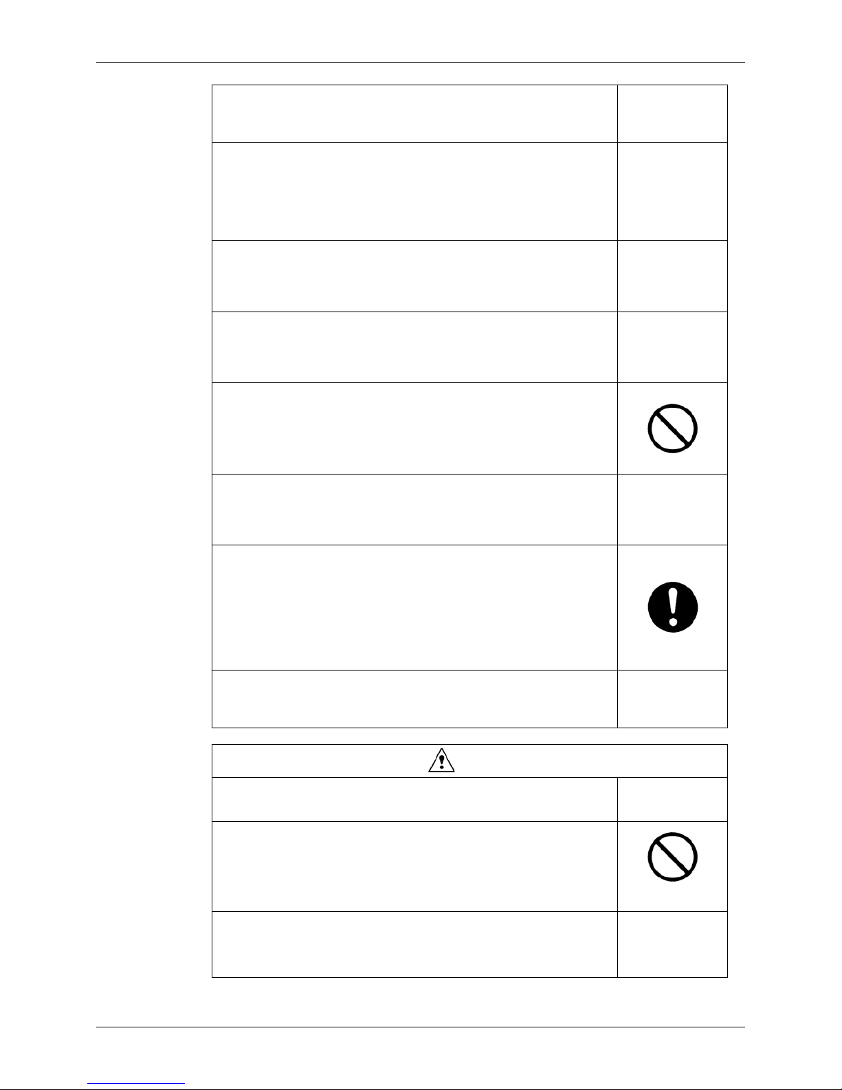
Be sure to install the product securely in the installation frame mounted on a
window frame.
If the unit is not securely mounted, it can fall and cause injury.
For integral units
only
Be sure to use an exclusive power circuit for the equipment, and follow the
technical standards related to the electrical equipment, the internal wiring
regulations and the instruction manual for installation when conducting
electrical work.
Insufficient power circuit capacity and improper electrical work can cause an
electrical shock or fire.
Be sure to use the specified cable to connect between the indoor and
outdoor units. Make the connections securely and route the cable properly so
that there is no force pulling the cable at the connection terminals.
Improper connections can cause excessive heat generation or fire.
When connecting the cable between the indoor and outdoor units, make sure
that the terminal cover does not lift off or dismount because of the cable.
If the cover is not mounted properly, the terminal connection section can
cause an electrical shock, excessive heat generation or fire.
Do not damage or modify the power cable.
Damaged or modified power cable can cause an electrical shock or fire.
Placing heavy items on the power cable, and heating or pulling the power
cable can damage the cable.
Do not mix air or gas other than the specified refrigerant (R410A) in the
refrigerant system.
If air enters the refrigerating system, an excessively high pressure results,
causing equipment damage and injury.
If the refrigerant gas leaks, be sure to locate the leak and repair it before
charging the refrigerant. After charging refrigerant, make sure that there is no
refrigerant leak.
If the leak cannot be located and the repair work must be stopped, be sure to
perform pump-down and close the service valve, to prevent the refrigerant
gas from leaking into the room. The refrigerant gas itself is harmless, but it
can generate toxic gases when it contacts flames, such as fan and other
heaters, stoves and ranges.
When replacing the coin battery in the remote controller, be sure to disposed
of the old battery to prevent children from swallowing it.
If a child swallows the coin battery, see a doctor immediately.
Caution
Installation of a leakage breaker is necessary in some cases depending on
the conditions of the installation site, to prevent electrical shocks.
Do not install the equipment in a place where there is a possibility of
combustible gas leaks.
If a combustible gas leaks and remains around the unit, it can cause a fire.
Be sure to install the packing and seal on the installation frame properly.
If the packing and seal are not installed properly, water can enter the room
and wet the furniture and floor.
For integral units
only
SiK401004_A
iv INTRODUCTION
1.1.3 Inspection after Repair
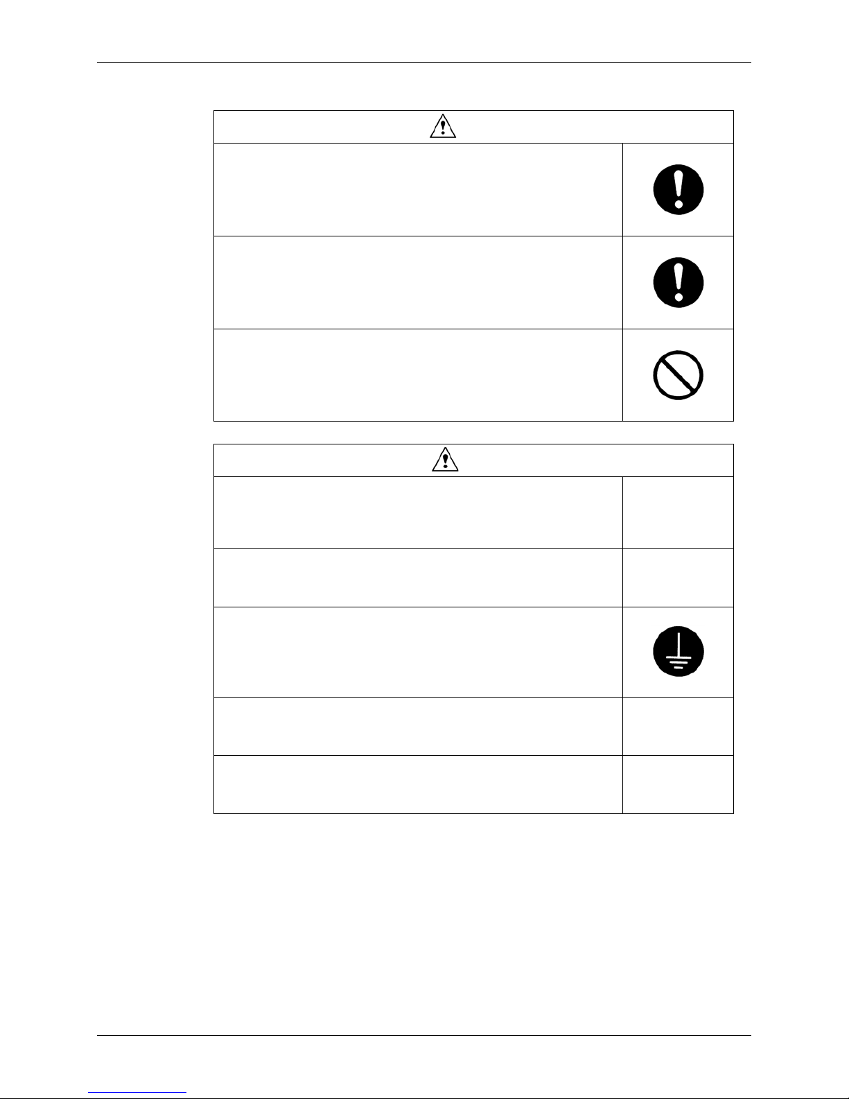
Warning
Check to make sure that the power cable plug is not dirty or loose, then insert
the plug into a power outlet all the way.
If the plug has dust or loose connection, it can cause an electrical shock or
fire.
If the power cable and lead wires have scratches or deteriorated, be sure to
replace them.
Damaged cable and wires can cause an electrical shock, excessive heat
generation or fire.
Do not use a joined power cable or extension cable, or share the same
power outlet with other electrical appliances, since it can cause an electrical
shock, excessive heat generation or fire.
Caution
Check to see if the parts and wires are mounted and connected properly, and
if the connections at the soldered or crimped terminals are secure.
Improper installation and connections can cause excessive heat generation,
fire or an electrical shock.
If the installation platform or frame has corroded, replace it.
Corroded installation platform or frame can cause the unit to fall, resulting in
injury.
Check the grounding, and repair it if the equipment is not properly grounded.
Improper grounding can cause an electrical shock.
Be sure to measure the insulation resistance after the repair, and make sure
that the resistance is 1 Mohm or higher.
Faulty insulation can cause an electrical shock.
Be sure to check the drainage of the indoor unit after the repair.
Faulty drainage can cause the water to enter the room and wet the furniture
and floor.
1.1.4 Using Icons
Icons are used to attract the attention of the reader to specific information. The meaning of
each icon is described in the table below:
SiK401004_A
INTRODUCTION v
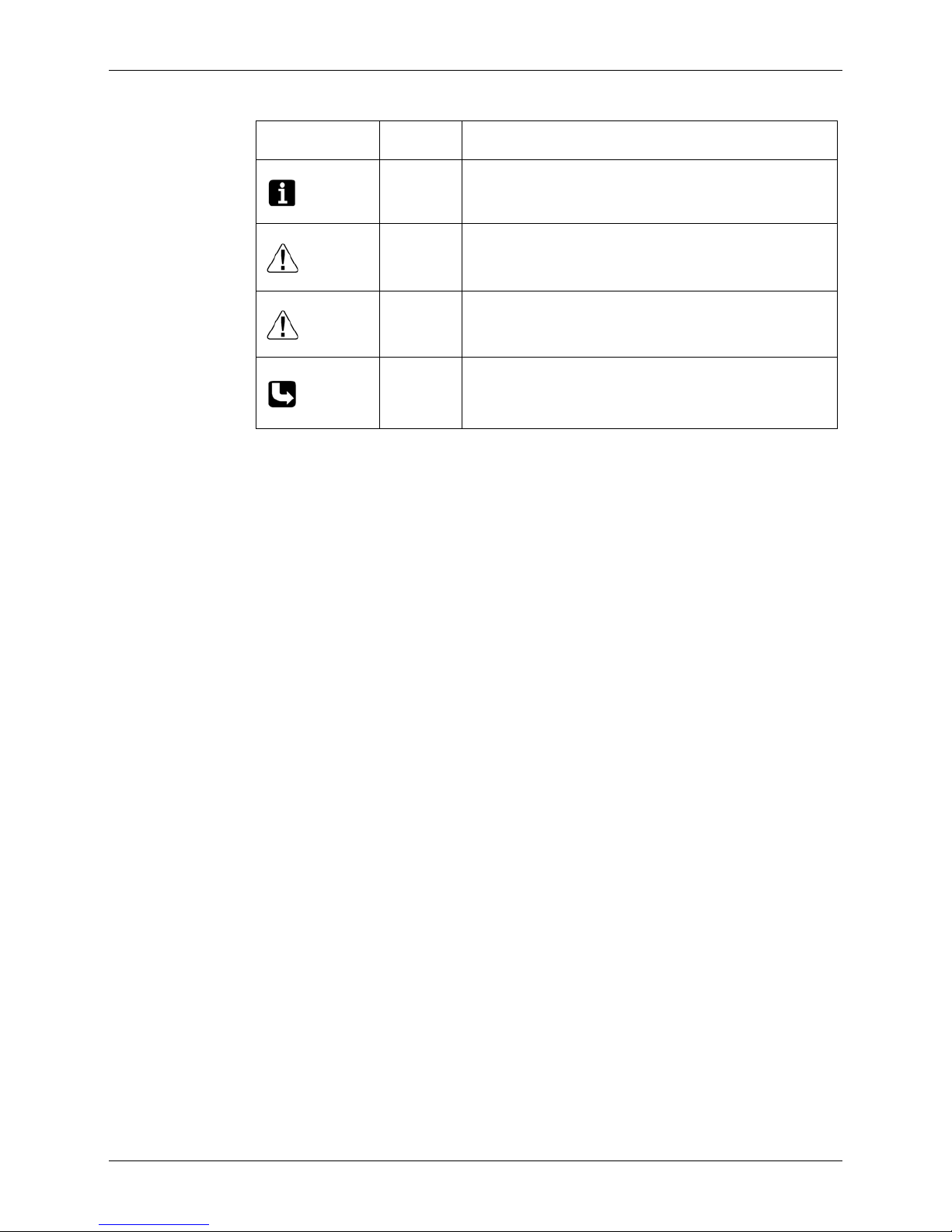
1.1.5 Using Icons List
Icon Type of
Information
Description
Note:
Note A “note” provides information that is not indispensable, but
may nevertheless be valuable to the reader, such as tips and
tricks.
Caution
Caution A “caution” is used when there is danger that the reader,
through incorrect manipulation, may damage equipment, loose
data, get an unexpected result or has to restart (part of) a
procedure.
Warning
Warning A “warning” is used when there is danger of personal injury.
Reference A “reference” guides the reader to other places in this binder or
in this manual, where he/she will find additional information on
a specific topic.

SiK401004_A
1 SPECIFICATIONS
Part1
SPECIFICATIONS
1. MODELS LIST .......................................................................................... 2
1.1 Outdoor Unit ............................................................................................. 2
1.2 Indoor Unit................................................................................................ 3
2. NOMENCLATURE.................................................................................... 4
3. FUNCTION ............................................................................................... 5
4. PRODUCT DATA ...................................................................................... 6
4.1 Product Data at Rated Condition.............................................................. 6
4.2 Electrical Data ........................................................................................ 27
5. PIPING DIAGRAM.................................................................................. 28
SiK401004_A
SPECIFICATIONS 2
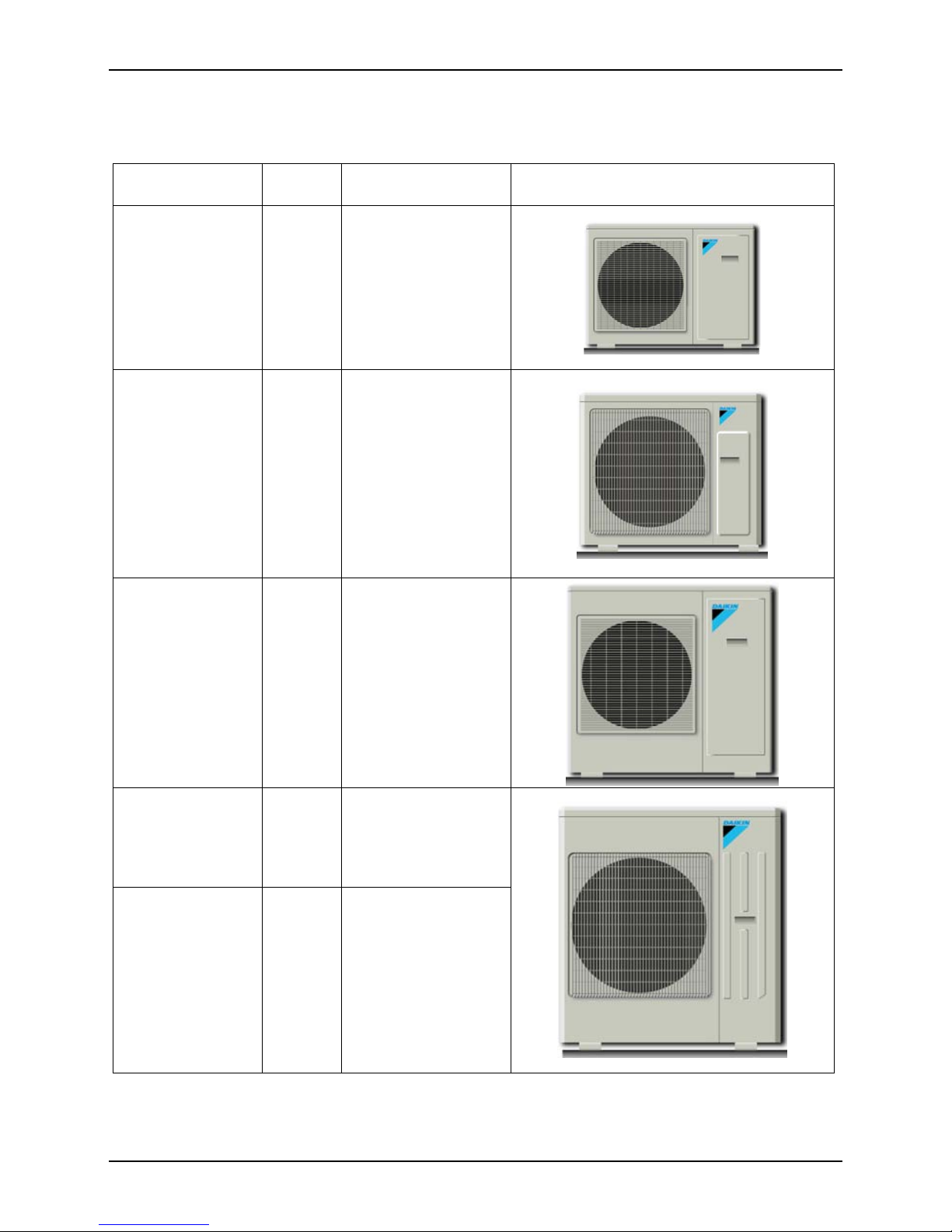
1. MODELS LIST
1.1 Outdoor Unit
Model Refrigerant Power Supply Appearance
RY24PEV1K
R24PEV1K
R22
220-240V 1PH 50Hz
RY30PEV1K
R30PEV1K
R22
220-240V 1PH 50Hz
RY36PEY1K
R36PEY1K
R22
380-415V 3PH 50Hz
RY42PEY1K
R42PEY1K
R22
380-415V 3PH 50Hz
RY48PEY1K
R48PEY1K
R22 380-415V 3PH 50Hz
SiK401004_A
3 SPECIFICATIONS
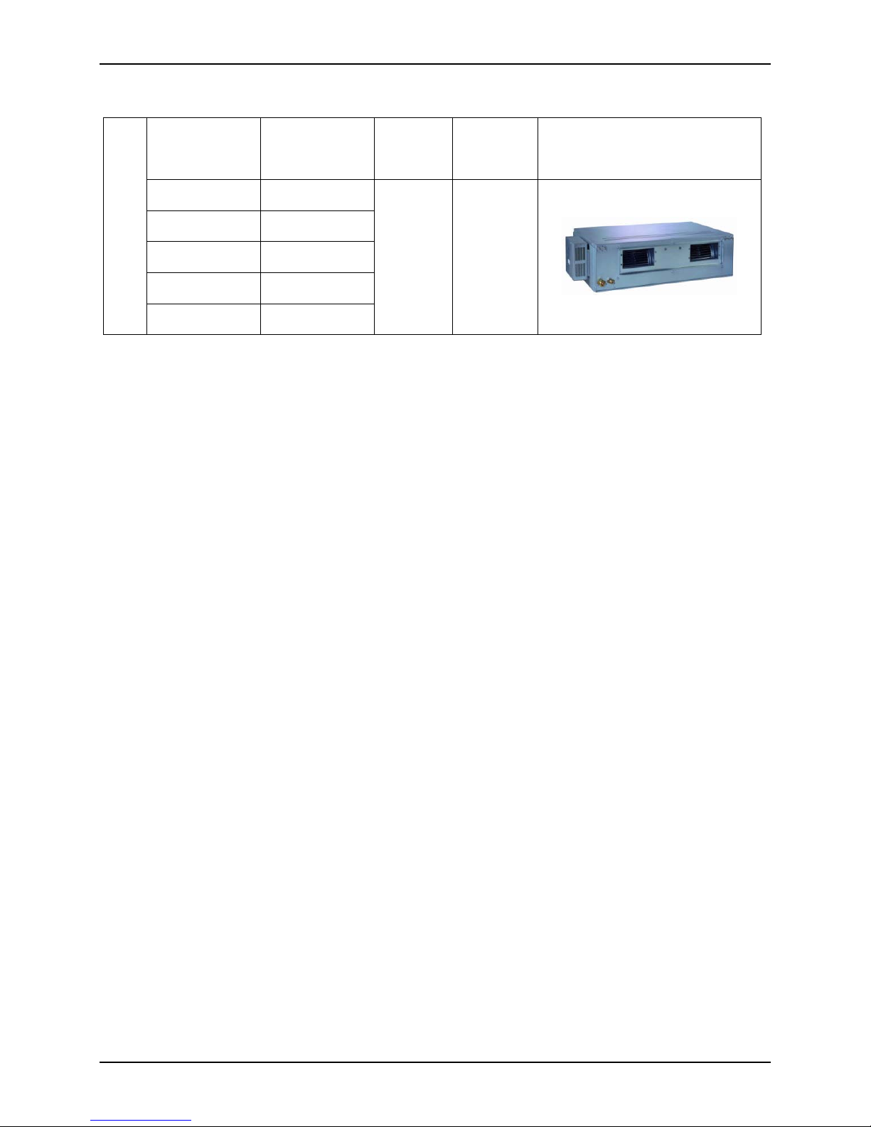
1.2 Indoor Unit
Model
Nominal Capacity
Cooling/Heating
(Btu/h)
Refrigerant
Power
Supply
Appearance
FD(Y)M24PEV1K 23200/25500
FD(Y)M30PEV1K 26300/32100
FD(Y)M36PEV1K 33000/41000
FD(Y)M42PEV1K 38600/46100
Type
FD(Y)M48PEV1K 44400/48200
R22
220-240V
1PH 50Hz
Note:1Ton =12000Btu/h = 3.517kW
Notes: The universal outdoor units means that the customer can choose any of three kind of indoor units to match the outdoor
unit without any change with it.
* Three kind of units
F = Duct Type
K = Cassette Type
T = Ceiling Type

SiK401004_A
SPECIFICATIONS 4
2. NOMENCLATURE
24
EK
M V1
SiK401004_A
5 SPECIFICATIONS
3. FUNCTION
Function Description
Memory function
For the air conditioners with this memory function setting, the units may start
automatically
after power failure reset or the main power supply is turned on again (when the unit
restarts , it will return to the same operation condition as that of the former operation
status, and the mode and parameter are also kept the same.)
Timing function it can make timing ON/ OFF separately, meanwhile, it can also make timing on circularly
Self-diagnosis with alarm
function
once unit has malfunction, the malfunction code will be indicated and alarm rings
immediately
Sleep function it can self control for saving energy in energy saving mode.
Automatic function
the fan of indoor unit can adjust fan speed automatically based on actual demand when
cooling or heating under automatic mode
Cool air protection function
the fan starts only when the temperature of indoor unit heat exchanger is higher than
indoor temperature under heating mode
High/low Pressure Protection
when suction pressure is too low or discharge pressure is too high, compressor will stop
and unit displays malfunction code
Overload protection
compressor has its own overheat protection, once the temperature of compressor is
higher than allowable level, compressor will stop and it can restart only when
temperature recovers.
Over current protection
once the current of compressor is higher that normal level, compressor will stop and unit
displays malfunction code
Discharge high
temperature protection
once the discharge temperature of compressor is higher than allowable level, compressor
will stop and unit displays malfunction code.
Reverse (open) phase
protection
once the phase sequence of power supply is incongruent or the phase is absent, unit
can’t work.
Anti-high
temperature protection
once the heat exchanger temperature of indoor unit is too high, the compressor will stop.
Timing ON/OFF display display and make timing turn ON/OFF time
Fan speed display display the speed (high.medium.low) of fan
Function model display cooling mode.dehumidifying mode.heating mode.fan mode
Testing display display testing mode
Temperature display display room temperature and set temperature
SiK401004_A
SPECIFICATIONS 6
4. PRODUCT DATA
4.1 Product Data at Rated Condition
4.1.1 Duct Type
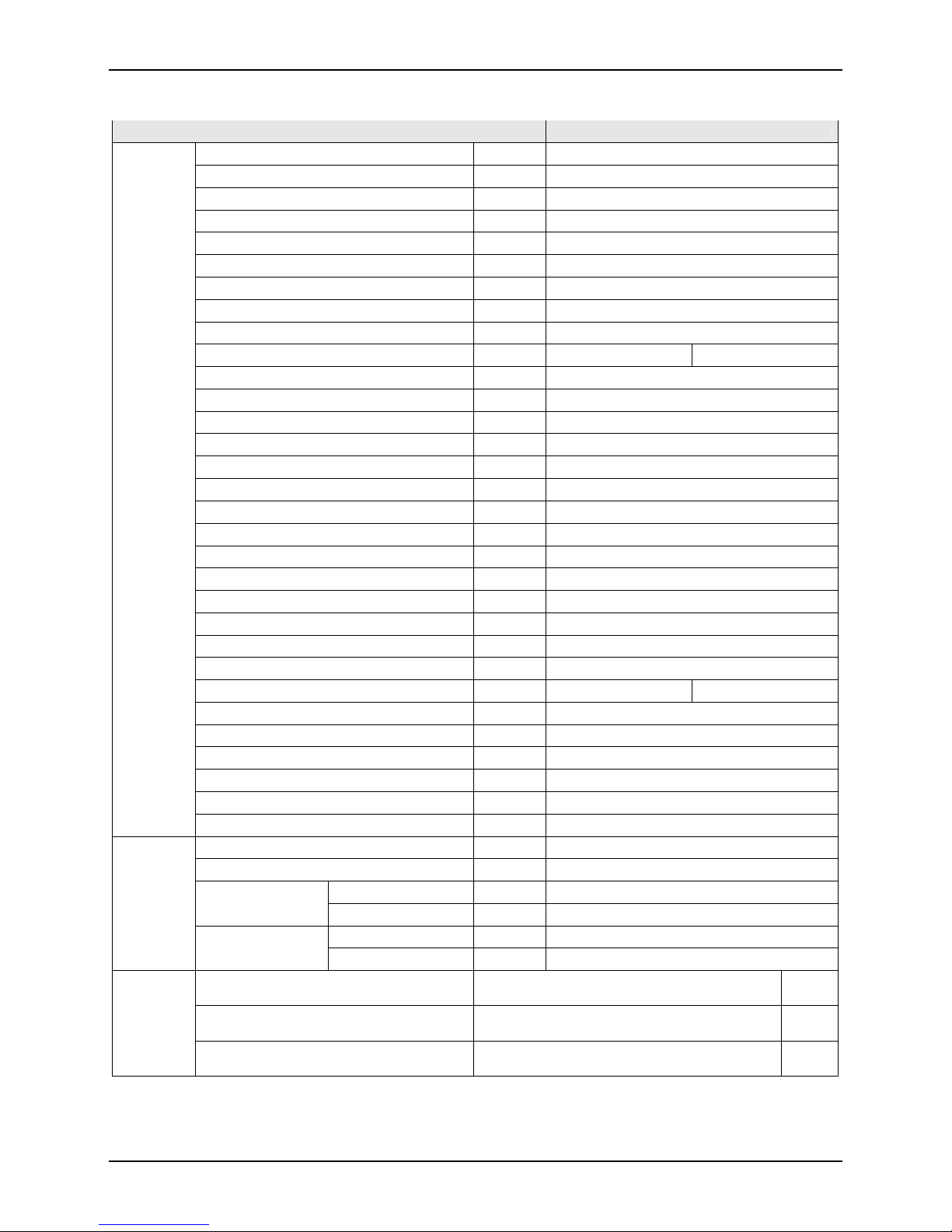
Outdoor R24PEV1K
Model
Indoor FDM24PEV1K
Function ― COOLING
Rated Voltage ― 220-240V 1Ph
Rated Frequency ― 50Hz
Total Capacity (Btu/h)/W
6800
23200
Power Input W 2500
Rated Current A 11.9
Max Current A 19.0
Air Flow Volume (H/M/L)**
m3/h
1600/1400/1200
ESP Pa 25
EER (Btu/h)/W 9.28
Indoor Unit FDM24PEV1K
Fan Motor Speed (H/M/L) r/min 1250/1220/1060
Output of Fan Motor W 150
Fan Motor Capacitor µF 8
Fan Type-Piece ― Centrifugal fan – 2
Diameter-Length mm φ160 – 200
Evaporator ― Aluminum fin-copper tube
Pipe Diameter mm φ9.52
Row-Fin Gap mm 2-1.8
Coil length (L) x height (H) x coil width (W) mm 1002X253X44
Fuse A 5
Sound Pressure Level dB (H/M/L) A 47/44/42
Sound Power Level dB (H/M/L) A 57/54/52
Dimension (W/H/D) mm 1270/268/530
Dimension of Package (W/H/D) mm 1345/283/594
Indoor
unit
Net Weight/Gross Weight kg 36/42

SiK401004_A
7 SPECIFICATIONS
Outdoor Unit R24PEV1K
Compressor ManµFacturer/trademark ― Mitsubishi
Compressor Model ― LHT42VBAC
Compressor Type ― Rotary
L.R.A. A 66
Compressor RLA A 11.2
Compressor Power Input W
2390
Overload Protector ― Auto Reset Thermal Overload
Throttling Method ― Capillary
Starting Method ― Start directly
Working Temp Range °C Cooling: 18°C-52°C
Condenser ― Aluminum fin-copper tube
Pipe Diameter mm φ9.52
Rows-Fin Gap mm 2-1.5
Coil length (L) x height (H) x coil width (W) mm 744X660X44
Fan Motor Speed rpm 940
Output of Fan Motor W 92
Fan Motor Capacitor µF 4
Air Flow Volume of Outdoor Unit 3200
Fan Type-Piece ― Axial fan –1
Fan Diameter mm φ450
Climate Type ― T3
Isolation ― I
Moisture Protection ― IP24
Design Pressure (Hi/Lo) MPa 2.5 0.6
Sound Pressure Level dB A 59
Sound Power Level dB (H/M/L) A 69
Dimension (W/H/D) mm 1018/695/412
Dimension of Package (W/H/D) mm 1100/755/450
Net Weight/Gross Weight kg 66/70
Outdoor
unit
Refrigerant Charge kg R22/2.5
Length m 5
Gas additional charge g/m 60
Liquid Pipe Inch φ3/8’’ Outer Diameter
Gas Pipe Inch φ5/8’’
Height m 15
Connection
Pipe
Max Distance
Length m 30
20’ Container
Interior Dimensions L*W*H: 5898*2352*2393,
Door Opening W*H: 2343*2280
37
40’ Container
Interior Dimensions L*W*H: 12032*2350*2390,
Door Opening W*H: 2343*2280
88
Loading
Quantity
40’ High Cube Container
Interior Dimensions L*W*H: 12032*2350*2697,
Door Opening W*H: 2338*2585
99

SiK401004_A
SPECIFICATIONS 8
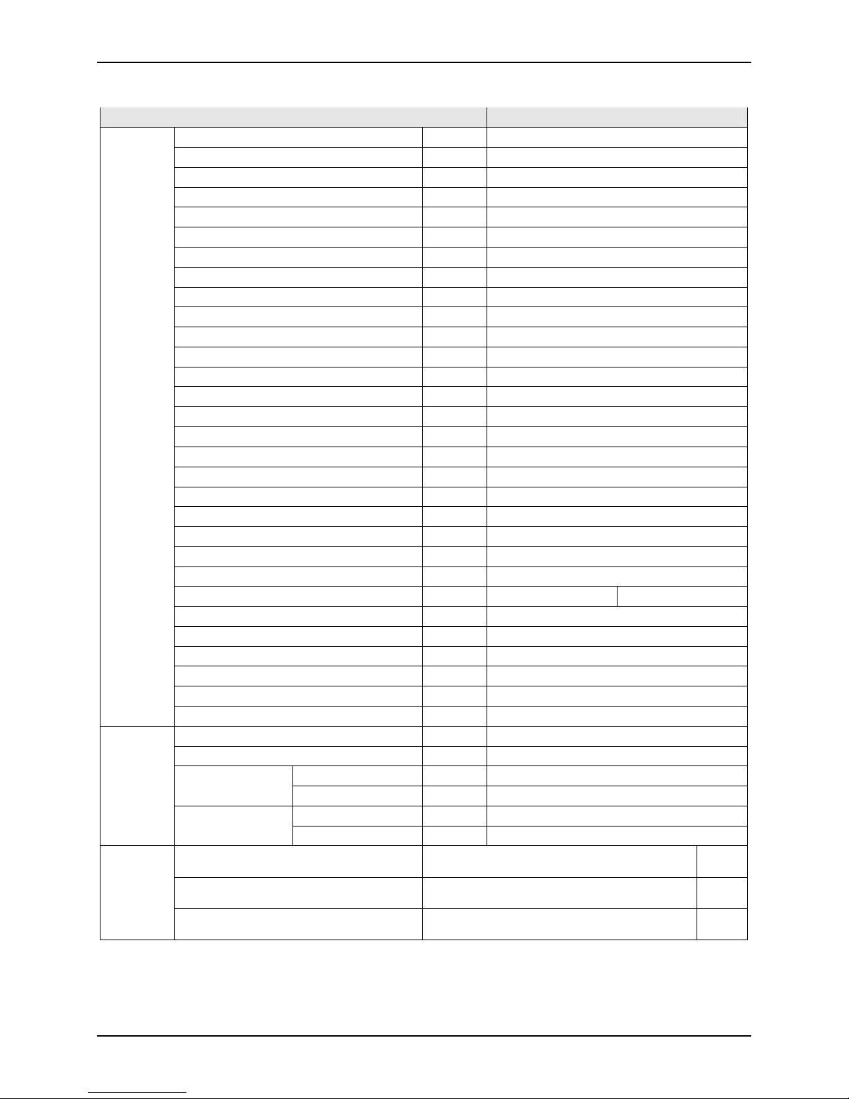
Outdoor R30PEV1K
Model
Indoor FDM30PEV1K
Function ― COOLING
Rated Voltage ― 220-240V 1Ph
Rated Frequency ― 50Hz
Total Capacity (Btu/h)/W
7700
26300
Power Input W 2920
Rated Current A 13.5
Max Current A 21.0
Air Flow Volume (H/M/L)**
m3/h
1500/1300/1100
ESP Pa 37
EER (Btu/h)/W 9.01
Indoor Unit FDM30PEV1K
Fan Motor Speed (H/M/L) r/min 1250/1220/1060
Output of Fan Motor W 150
Fan Motor Capacitor µF 8
Fan Type-Piece ― Centrifugal fan – 2
Diameter-Length mm φ160 – 200
Evaporator ― Aluminum fin-copper tube
Pipe Diameter mm φ9.52
Row-Fin Gap mm 2-1.8
Coil length (L) x height (H) x coil width (W) mm 1002X253X44
Fuse A 5
Sound Pressure Level dB (H/M/L) A 47/44/42
Sound Power Level dB (H/M/L) A 57/54/52
Dimension (W/H/D) mm 1270/268/530
Dimension of Package (W/H/D) mm 1345/283/594
Indoor
unit
Net Weight/Gross Weight kg 36/42

SiK401004_A
9 SPECIFICATIONS
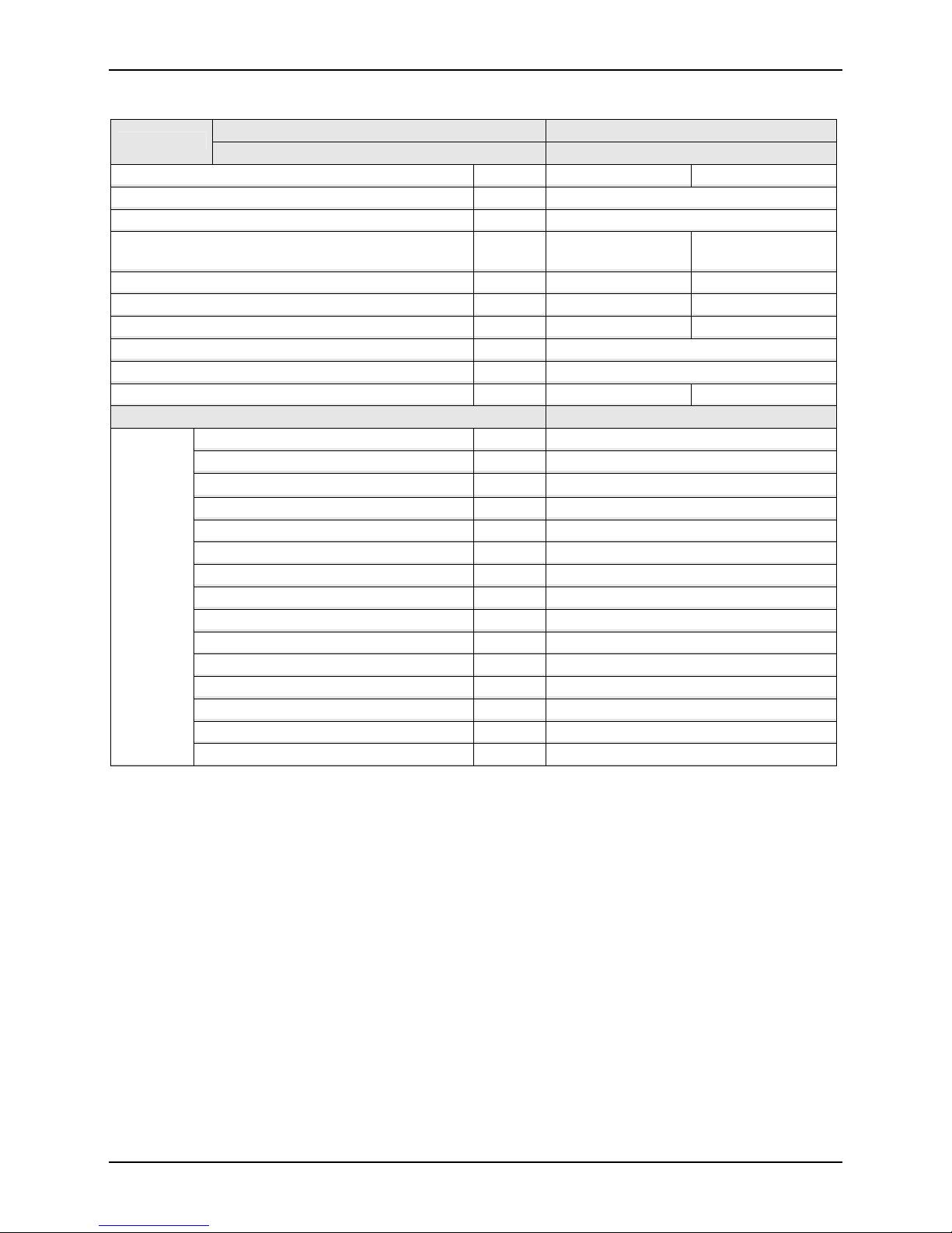
Outdoor Unit R30PEV1K
Compressor ManµFacturer/trademark ― Mitsubishi
Compressor Model ― LHT53VBAC
Compressor Type ― Rotary
L.R.A. A 76
Compressor RLA A 14.8
Compressor Power Input W
3050
Overload Protector ― Auto Reset Thermal Overload
Throttling Method ― Capillary
Starting Method ― Start directly
Working Temp Range °C Cooling: 18°C-52°C
Condenser ― Aluminum fin-copper tube
Pipe Diameter mm φ9.52
Rows-Fin Gap mm 2-1.6
Coil length (L) x height (H) x coil width (W) mm 976X762X44
Fan Motor Speed rpm 780
Output of Fan Motor W 125
Fan Motor Capacitor µF 7
Air Flow Volume of Outdoor Unit 4200
Fan Type-Piece ― Axial fan –1
Fan Diameter mm φ552
Climate Type ― T3
Isolation ― I
Moisture Protection ― IP24
Design Pressure (Hi/Lo) MPa 2.5 0.6
Sound Pressure Level dB A 58
Sound Power Level dB (H/M/L) A 68
Dimension (W/H/D) mm 980/790/427
Dimension of Package (W/H/D) mm 1080/840/485
Net Weight/Gross Weight kg 73/77
Outdoor
unit
Refrigerant Charge kg R22/3.4
Length m 5
Gas additional charge g/m 60
Liquid Pipe Inch φ3/8’’ Outer Diameter
Gas Pipe Inch φ5/8’’
Height m 15
Connection
Pipe
Max Distance
Length m 30
20’ Container
Interior Dimensions L*W*H: 5898*2352*2393,
Door Opening W*H: 2343*2280
34
40’ Container
Interior Dimensions L*W*H: 12032*2350*2390,
Door Opening W*H: 2343*2280
74
Loading
Quantity
40’ High Cube Container
Interior Dimensions L*W*H: 12032*2350*2697,
Door Opening W*H: 2338*2585
83

SiK401004_A
SPECIFICATIONS 10
Outdoor R36PEY1K
Model
Indoor FDM36PEV1K
Function ― COOLING
Rated Voltage ― 380-415V 3Ph
Rated Frequency ― 50Hz
Total Capacity (Btu/h)/W
9700
33000
Power Input W 3900
Rated Current A 7.1
Max Current A 10.6
Air Flow Volume (H/M/L)**
m3/h
2000/1900/1800
ESP Pa 37
EER (Btu/h)/W 8.46
Indoor Unit FDM36PEV1K
Fan Motor Speed (H/M/L) r/min 1320/1090/910
Output of Fan Motor W 500
Fan Motor Capacitor µF 12
Fan Type-Piece ― Centrifugal fan – 2
Diameter-Length mm φ200 – 190
Evaporator ― Aluminum fin-copper tube
Pipe Diameter mm φ7
Row-Fin Gap mm 3-1.6
Coil length (L) x height (H) x coil width (W) mm 978X304.8X38.1
Fuse A 5
Sound Pressure Level dB (H/M/L) A 50/48/46
Sound Power Level dB (H/M/L) A 60/58/56
Dimension (W/H/D) mm 1226/290/775
Dimension of Package (W/H/D) mm 1335/305/834
Indoor
unit
Net Weight/Gross Weight kg 53/61

SiK401004_A
11 SPECIFICATIONS
Outdoor Unit R36PEY1K
Compressor ManµFacturer/trademark ― SANYO
Compressor Model ― C-SBR145H38P
Compressor Type ― SCROLL
L.R.A. A 53
Compressor RLA A 6.5
Compressor Power Input W
3650
Overload Protector ― Auto Reset Thermal Overload
Throttling Method ― Capillary
Starting Method ― Start directly
Working Temp Range °C Cooling: 18°C-52°C
Condenser ― Aluminum fin-copper tube
Pipe Diameter mm φ9.52
Rows-Fin Gap mm 2-1.4
Coil length (L) x height (H) x coil width (W) mm 964X813X44
Fan Motor Speed rpm 920
Output of Fan Motor W 92
Fan Motor Capacitor µF 4
Air Flow Volume of Outdoor Unit 4000
Fan Type-Piece ― Axial fan –1
Fan Diameter mm φ482
Climate Type ― T3
Isolation ― I
Moisture Protection ― IP24
Design Pressure (Hi/Lo) MPa 2.5 0.6
Sound Pressure Level dB A 60
Sound Power Level dB (H/M/L) A 70
Dimension (W/H/D) mm 1018/840/412
Dimension of Package (W/H/D) mm 1100/985/450
Net Weight/Gross Weight kg 89/97
Outdoor
unit
Refrigerant Charge kg R22/3.6
Length m 5
Gas additional charge g/m 120
Liquid Pipe Inch φ1/2’’ Outer Diameter
Gas Pipe Inch φ3/4’’
Height m 30
Connection
Pipe
Max Distance
Length m 50
20’ Container
Interior Dimensions L*W*H: 5898*2352*2393,
Door Opening W*H: 2343*2280
30
40’ Container
Interior Dimensions L*W*H: 12032*2350*2390,
Door Opening W*H: 2343*2280
60
Loading
Quantity
40’ High Cube Container
Interior Dimensions L*W*H: 12032*2350*2697,
Door Opening W*H: 2338*2585
66
SiK401004_A
SPECIFICATIONS 12
Outdoor R42PEY1K
Model
Indoor FDM42PEV1K
Function ― COOLING
Rated Voltage ― 380-415V 3Ph
Rated Frequency ― 50Hz
Total Capacity (Btu/h)/W
11300
38600
Power Input W 4600
Rated Current A 8.9
Max Current A 13.0
Air Flow Volume (H/M/L)**
m3/h
2000/1900/1800
ESP Pa 37
EER (Btu/h)/W 8.39
Indoor Unit FDM42PEV1K
Fan Motor Speed (H/M/L) r/min 1320/1090/910
Output of Fan Motor W 500
Fan Motor Capacitor µF 12
Fan Type-Piece ― Centrifugal fan – 2
Diameter-Length mm φ200 – 190
Evaporator ― Aluminum fin-copper tube
Pipe Diameter mm φ7
Row-Fin Gap mm 3-1.6
Coil length (L) x height (H) x coil width (W) mm 978X304.8X38.1
Fuse A 5
Sound Pressure Level dB (H/M/L) A 50/48/46
Sound Power Level dB (H/M/L) A 60/58/56
Dimension (W/H/D) mm 1226/290/775
Dimension of Package (W/H/D) mm 1335/305/834
Indoor
unit
Net Weight/Gross Weight kg 53/61

SiK401004_A
13 SPECIFICATIONS
Outdoor Unit R42PEY1K
Compressor ManµFacturer/trademark ― SANYO
Compressor Model ― C-SBX180H38P
Compressor Type ― SCROLL
L.R.A. A 73
Compressor RLA A 8.06
Compressor Power Input W
4300
Overload Protector ― Auto Reset Thermal Overload
Throttling Method ― Capillary
Starting Method ― Direct
Working Temp Range °C Cooling: 18°C-52°C
Condenser ― Aluminum fin-copper tube
Pipe Diameter mm φ9.52
Rows-Fin Gap mm 1-1.4
Coil length (L) x height (H) x coil width (W) mm 1050/1067X22
Fan Motor Speed rpm 820
Output of Fan Motor W 140
Fan Motor Capacitor µF 7
Air Flow Volume of Outdoor Unit 6000
Fan Type-Piece ― Axial fan –1
Fan Diameter mm φ570
Climate Type ― T3
Isolation ― I
Moisture Protection ― IP24
Design Pressure (Hi/Lo) MPa 2.5 0.6
Sound Pressure Level dB A 60
Sound Power Level dB (H/M/L) A 70
Dimension (W/H/D) mm 1107/1100/440
Dimension of Package (W/H/D) mm 1170/1220/490
Net Weight/Gross Weight kg 94/104
Outdoor
unit
Refrigerant Charge kg R22/3.05
Length m 5
Gas additional charge g/m 120
Liquid Pipe Inch φ1/2’’ Outer Diameter
Gas Pipe Inch φ3/4’’
Height m 30
Connection
Pipe
Max Distance
Length m 50
20’ Container
Interior Dimensions L*W*H: 5898*2352*2393,
Door Opening W*H: 2343*2280
20
40’ Container
Interior Dimensions L*W*H: 12032*2350*2390,
Door Opening W*H: 2343*2280
39
Loading
Quantity
40’ High Cube Container
Interior Dimensions L*W*H: 12032*2350*2697,
Door Opening W*H: 2338*2585
48

SiK401004_A
SPECIFICATIONS 14
Outdoor R48PEY1K
Model
Indoor FDM48PEV1K
Function ― COOLING
Rated Voltage ― 380-415V 3Ph
Rated Frequency ― 50Hz
Total Capacity (Btu/h)/W
13000
44400
Power Input W 5400
Rated Current A 10.4
Max Current A 14.5
Air Flow Volume (H/M/L)**
m3/h
2300/2110/1850
ESP Pa 50
EER/C.O.P (Btu/h)/W 8.22
Indoor Unit FDM48PEV1K
Fan Motor Speed (H/M/L) r/min 1320/1090/910
Output of Fan Motor W 500
Fan Motor Capacitor µF 12
Fan Type-Piece ― Centrifugal fan – 2
Diameter-Length mm φ200 – 190
Evaporator ― Aluminum fin-copper tube
Pipe Diameter mm φ9.52
Row-Fin Gap mm 3-1.8
Coil length (L) x height (H) x coil width (W) mm 978X304.8/66
Fuse A 5
Sound Pressure Level dB (H/M/L) A 53/50/46
Sound Power Level dB (H/M/L) A 63/60/56
Dimension (W/H/D) mm 1226/290/775
Dimension of Package (W/H/D) mm 1335/305/834
Indoor
unit
Net Weight/Gross Weight kg 55/63
SiK401004_A
15 SPECIFICATIONS
Outdoor Unit R48PEY1K
Compressor ManµFacturer/trademark ― SANYO
Compressor Model ― C-SBX215H38P
Compressor Type ― SCROLL
L.R.A. A 73
Compressor RLA A 9.4
Compressor Power Input W
5350
Overload Protector ― Auto Reset Thermal Overload
Throttling Method ― Capillary
Starting Method ― Direct
Working Temp Range °C Cooling: 18°C-52°C
Condenser ― Aluminum fin-copper tube
Pipe Diameter mm φ9.52
Rows-Fin Gap mm 2-1.4
Coil length (L) x height (H) x coil width (W) mm 1050X1067X44
Fan Motor Speed rpm 820
Output of Fan Motor W 140
Fan Motor Capacitor µF 7
Air Flow Volume of Outdoor Unit 6000
Fan Type-Piece ― Axial fan –1
Fan Diameter mm φ570
Climate Type ― T3
Isolation ― I
Moisture Protection ― IP24
Design Pressure (Hi/Lo) MPa 2.5 0.6
Sound Pressure Level dB A 60
Sound Power Level dB (H/M/L) A 70
Dimension (W/H/D) mm 1107/1100/440
Dimension of Package (W/H/D) mm 1170/1220/490
Net Weight/Gross Weight kg 107/116
Outdoor
unit
Refrigerant Charge kg R22/5.0
Length m 5
Gas additional charge g/m 120
Liquid Pipe Inch φ1/2’’ Outer Diameter
Gas Pipe Inch φ3/4’’
Height m 30
Connection
Pipe
Max Distance
Length m 50
20’ Container
Interior Dimensions L*W*H: 5898*2352*2393,
Door Opening W*H: 2343*2280
20
40’ Container
Interior Dimensions L*W*H: 12032*2350*2390,
Door Opening W*H: 2343*2280
39
Loading
Quantity
40’ High Cube Container
Interior Dimensions L*W*H: 12032*2350*2697,
Door Opening W*H: 2338*2585
48
SiK401004_A
SPECIFICATIONS 16
Outdoor RY24PEV1K
Model
Indoor FDYM24PEV1K
Function ― COOLING HEATING
Rated Voltage ― 220-240V 1Ph
Rated Frequency ― 50Hz
Total Capacity (Btu/h)/W
6800
23200
7500
25500
Power Input W 2500 2450
Rated Current A 11.9 12.4
Max Current A 18.3 15.8
Air Flow Volume (H/M/L)**
m3/h
1600/1400/1200
ESP Pa 25
EER/C.O.P (Btu/h)/W 9.28 3.06
Indoor Unit FDYM24PEV1K
Fan Motor Speed (H/M/L) r/min 1250/1220/1060
Output of Fan Motor W 150
Fan Motor Capacitor µF 8
Fan Type-Piece ― Centrifugal fan – 2
Diameter-Length mm φ160 – 200
Evaporator ― Aluminum fin-copper tube
Pipe Diameter mm φ9.52
Row-Fin Gap mm 2-1.8
Coil length (L) x height (H) x coil width (W) mm 1002X253X44
Fuse A 5
Sound Pressure Level dB (H/M/L) A 47/44/42
Sound Power Level dB (H/M/L) A 57/54/52
Dimension (W/H/D) mm 1270/268/530
Dimension of Package (W/H/D) mm 1345/283/594
Indoor
unit
Net Weight/Gross Weight kg 36/42

SiK401004_A
17 SPECIFICATIONS
Outdoor Unit RY24PEV1K
Compressor ManµFacturer/trademark ― Mitsubishi
Compressor Model ― LHT42VBAC
Compressor Type ― Rotary
L.R.A. A 66
Compressor RLA A 11.2
Compressor Power Input W
2390
Overload Protector ― Auto Reset Thermal Overload
Throttling Method ― Capillary
Starting Method ― Start directly
Working Temp Range °C Cooling: 18°C-52°C Heating: -7°C-24°C
Condenser ― Aluminum fin-copper tube
Pipe Diameter mm φ9.52
Rows-Fin Gap mm 2-1.5
Coil length (L) x height (H) x coil width (W) mm 744X660X44
Fan Motor Speed rpm 940
Output of Fan Motor W 92
Fan Motor Capacitor µF 4
Air Flow Volume of Outdoor Unit 3200
Fan Type-Piece ― Axial fan –1
Fan Diameter mm φ450
Defrosting Method ― Auto defrost
Climate Type ― T3
Isolation ― I
Moisture Protection ― IP24
Design Pressure (Hi/Lo) MPa 2.5 0.6
Sound Pressure Level dB A 59
Sound Power Level dB (H/M/L) A 69
Dimension (W/H/D) mm 1018/695/412
Dimension of Package (W/H/D) mm 1100/755/450
Net Weight/Gross Weight kg 67/71
Outdoor
unit
Refrigerant Charge kg R22/2.5
Length m 5
Gas additional charge g/m 60
Liquid Pipe Inch φ3/8’’ Outer Diameter
Gas Pipe Inch φ5/8’’
Height m 15
Connection
Pipe
Max Distance
Length m 30
20’ Container
Interior Dimensions L*W*H: 5898*2352*2393,
Door Opening W*H: 2343*2280
37
40’ Container
Interior Dimensions L*W*H: 12032*2350*2390,
Door Opening W*H: 2343*2280
88
Loading
Quantity
40’ High Cube Container
Interior Dimensions L*W*H: 12032*2350*2697,
Door Opening W*H: 2338*2585
99

SiK401004_A
SPECIFICATIONS 18
Outdoor RY30PEV1K
Model
Indoor FDYM30PEV1K
Function ― COOLING HEATING
Rated Voltage ― 220-240V 1Ph
Rated Frequency ― 50Hz
Total Capacity (Btu/h)/W
7700
26300
9400
32100
Power Input W 2950 3300
Rated Current A 14.5 16.8
Max Current A 21.0 19.0
Air Flow Volume (H/M/L)**
m3/h
1500/1300/1100
ESP Pa 37
EER/C.O.P (Btu/h)/W 8.92 2.85
Indoor Unit FDYM30PEV1K
Fan Motor Speed (H/M/L) r/min 1250/1220/1060
Output of Fan Motor W 150
Fan Motor Capacitor µF 8
Fan Type-Piece ― Centrifugal fan – 2
Diameter-Length mm φ160 – 200
Evaporator ― Aluminum fin-copper tube
Pipe Diameter mm φ9.52
Row-Fin Gap mm 2-1.8
Coil length (L) x height (H) x coil width (W) mm 1002X253X44
Fuse A 5
Sound Pressure Level dB (H/M/L) A 47/44/42
Sound Power Level dB (H/M/L) A 57/54/52
Dimension (W/H/D) mm 1270/268/530
Dimension of Package (W/H/D) mm 1345/283/594
Indoor
unit
Net Weight/Gross Weight kg 36/42
SiK401004_A
19 SPECIFICATIONS
Outdoor Unit RY30PEV1K
Compressor ManµFacturer/trademark ― Mitsubishi
Compressor Model ― LHT53VBAC
Compressor Type ― Rotary
L.R.A. A 76
Compressor RLA A 14.8
Compressor Power Input W
3050
Overload Protector ― Auto Reset Thermal Overload
Throttling Method ― Capillary
Starting Method ― Start directly
Working Temp Range °C Cooling: 18°C-52°C Heating: -7°C-24°C
Condenser ― Aluminum fin-copper tube
Pipe Diameter mm φ9.52
Rows-Fin Gap mm 2-1.6
Coil length (L) x height (H) x coil width (W) mm 976X762X44
Fan Motor Speed rpm 780
Output of Fan Motor W 125
Fan Motor Capacitor µF 7
Air Flow Volume of Outdoor Unit 4200
Fan Type-Piece ― Axial fan –1
Fan Diameter mm φ552
Defrosting Method ― Auto defrost
Climate Type ― T3
Isolation ― I
Moisture Protection ― IP24
Design Pressure (Hi/Lo) MPa 2.5 0.6
Sound Pressure Level dB A 58
Sound Power Level dB (H/M/L) A 68
Dimension (W/H/D) mm 980/790/427
Dimension of Package (W/H/D) mm 1080/840/485
Net Weight/Gross Weight kg 74/78
Outdoor
unit
Refrigerant Charge kg R22/3.4
Length m 5
Gas additional charge g/m 60
Liquid Pipe Inch φ3/8’’ Outer Diameter
Gas Pipe Inch φ5/8’’
Height m 15
Connection
Pipe
Max Distance
Length m 30
20’ Container
Interior Dimensions L*W*H: 5898*2352*2393,
Door Opening W*H: 2343*2280
34
40’ Container
Interior Dimensions L*W*H: 12032*2350*2390,
Door Opening W*H: 2343*2280
74
Loading
Quantity
40’ High Cube Container
Interior Dimensions L*W*H: 12032*2350*2697,
Door Opening W*H: 2338*2585
83

SiK401004_A
SPECIFICATIONS 20
Outdoor RY36PEY1K
Model
Indoor FDYM36PEV1K
Function ― COOLING HEATING
Rated Voltage ― 380-415V 3Ph
Rated Frequency ― 50Hz
Total Capacity (Btu/h)/W
9700
33000
12000
41000
Power Input W 3900 3450
Rated Current A 7.2 6.7
Max Current A 10.3 8.0
Air Flow Volume (H/M/L)**
m3/h
2000/1900/1800
ESP Pa 37
EER/C.O.P (Btu/h)/W 8.46 3.48
Indoor Unit FDYM36PEV1K
Fan Motor Speed (H/M/L) r/min 1320/1090/910
Output of Fan Motor W 500
Fan Motor Capacitor µF 12
Fan Type-Piece ― Centrifugal fan – 2
Diameter-Length mm φ200 – 190
Evaporator ― Aluminum fin-copper tube
Pipe Diameter mm φ7
Row-Fin Gap mm 3-1.6
Coil length (L) x height (H) x coil width (W) mm 978X304.8X38.1
Fuse A 5
Sound Pressure Level dB (H/M/L) A 50/48/46
Sound Power Level dB (H/M/L) A 60/58/56
Dimension (W/H/D) mm 1226/290/775
Dimension of Package (W/H/D) mm 1335/305/834
Indoor
unit
Net Weight/Gross Weight kg 53/61

SiK401004_A
21 SPECIFICATIONS
Outdoor Unit RY36PEY1K
Compressor ManµFacturer/trademark ― SANYO
Compressor Model ― C-SBR145H38P
Compressor Type ― SCROLL
L.R.A. A 53
Compressor RLA A 6.5
Compressor Power Input W
3650
Overload Protector ― Auto Reset Thermal Overload
Throttling Method ― Capillary
Starting Method ― Start directly
Working Temp Range °C Cooling: 18°C-52°C Heating: -7°C-24°C
Condenser ― Aluminum fin-copper tube
Pipe Diameter mm φ9.52
Rows-Fin Gap mm 2-1.4
Coil length (L) x height (H) x coil width (W) mm 964X813X44
Fan Motor Speed rpm 920
Output of Fan Motor W 92
Fan Motor Capacitor µF 4
Air Flow Volume of Outdoor Unit 4000
Fan Type-Piece ― Axial fan –1
Fan Diameter mm φ482
Defrosting Method ― Auto defrost
Climate Type ― T3
Isolation ― I
Moisture Protection ― IP24
Design Pressure (Hi/Lo) MPa 2.5 0.6
Sound Pressure Level dB A 61
Sound Power Level dB (H/M/L) A 71
Dimension (W/H/D) mm 1018/840/412
Dimension of Package (W/H/D) mm 1100/985/450
Net Weight/Gross Weight kg 90/98
Outdoor
unit
Refrigerant Charge kg R22/3.6
Length m 5
Gas additional charge g/m 120
Liquid Pipe Inch φ1/2’’ Outer Diameter
Gas Pipe Inch φ3/4’’
Height m 30
Connection
Pipe
Max Distance
Length m 50
20’ Container
Interior Dimensions L*W*H: 5898*2352*2393,
Door Opening W*H: 2343*2280
30
40’ Container
Interior Dimensions L*W*H: 12032*2350*2390,
Door Opening W*H: 2343*2280
60
Loading
Quantity
40’ High Cube Container
Interior Dimensions L*W*H: 12032*2350*2697,
Door Opening W*H: 2338*2585
66

SiK401004_A
SPECIFICATIONS 22
Outdoor RY42PEY1K
Model
Indoor FDYM42PEV1K
Function ― COOLING HEATING
Rated Voltage ― 380-415V 3Ph
Rated Frequency ― 50Hz
Total Capacity (Btu/h)/W
11300
38600
13500
46100
Power Input W 4800 4150
Rated Current A 9.3 8.1
Max Current A 12.5 9.7
Air Flow Volume (H/M/L)**
m3/h
2000/1900/1800
ESP Pa 37
EER/C.O.P (Btu/h)/W 8.04 3.25
Indoor Unit FDYM42PEV1K
Fan Motor Speed (H/M/L) r/min 1320/1090/910
Output of Fan Motor W 500
Fan Motor Capacitor µF 12
Fan Type-Piece ― Centrifugal fan – 2
Diameter-Length mm φ200 – 190
Evaporator ― Aluminum fin-copper tube
Pipe Diameter mm φ7
Row-Fin Gap mm 3-1.6
Coil length (L) x height (H) x coil width (W) mm 978X304.8X38.1
Fuse A 5
Sound Pressure Level dB (H/M/L) A 50/48/46
Sound Power Level dB (H/M/L) A 60/58/56
Dimension (W/H/D) mm 1226/290/775
Dimension of Package (W/H/D) mm 1335/305/834
Indoor
unit
Net Weight/Gross Weight kg 53/61
 Loading...