

Daikin FDM28CXV1, FDM20CXV1, FDM30CXV1, FDM38CXV1, FDM40CXV1 Technical Manual
...
TECHNICAL MANUAL
Split Unit Air Conditioner
Ceiling Concealed Series
FDM-C, FDB-C, FDYM-C, FDYB-C Series
— Cooling only & Heatpump [50Hz] —
R22


Table of Contents
Table of Contents
Nomenclature......................................................................................................................1
Indoor ............................................................................................................................1
Outdoor ..........................................................................................................................1
Product Line-Up .............................................................................................................2
Application Information .....................................................................................................4
Operating Range ...........................................................................................................4
Refrigerant Circuit Diagrams .........................................................................................5
Installation Guideline ................................................................................................... 11
Sound Data ........................................................................................................................17
Sound Power Level .....................................................................................................17
Sound Pressure Level .................................................................................................18
NC Curve ..................................................................................................................... 19
Selection Process.............................................................................................................28
Engineering & Physical Data ...........................................................................................46
Performance Data .............................................................................................................60
Calculation Steps .........................................................................................................60
Performance Tables .....................................................................................................62
Outlines & Dimensions ..................................................................................................125
Wiring Diagrams .............................................................................................................130
Service & Maintenance ..................................................................................................148
Troubleshooting .............................................................................................................150

Nomenclature
1
Nomenclature
Indoor
FD(Y)(B)(M) 10 C X V1
Power Supply
V1: 1 phase 50 Hz 220-240V
Production
X: OYLM
Product Series
C: C Series
Capacity
10: 10000 Btu/hr
Model
FDM: Ceiling Concealed Standard Static (Cooling Only)
FDYM: Ceiling Concealed Standard Static (Heatpump)
FDB: Ceiling Concealed Low Static (Cooling Only)
FDYB: Ceiling Concealed Low Static (Heatpump)
Outdoor
R(Y) 10 C X V1
Power Supply
V1: 1 phase 50 Hz 220-240V
Y1: 3 phase 50 Hz 380-415V
Production
X: OYLM
Product Series
C: C Series
D: D Series
Capacity
10: 10000 Btu/hr
Model
R: Single Split Condensing Unit (Cooling Only)
RY: Single Split Condensing Unit (Heatpump)

Nomenclature
2
Product Line-Up
Indoor Unit
FD(Y)M / FD(Y)B
Nomenclature
Classifi cation
Handset
PCB
Fin
Refrigerant Control
Air Purifi cation
Others
BRC51A62
BRC51A61
L208A EC
L208A AP
Bare Aluminium
Cap Tube
Without Cap Tube
Air Filter
Built-in Filter Rail
COOLING
FDM10CXV1 XXXXX
FDM15CXV1 XXXXX
FDM20CXV1 XXXXX
FDM25CXV1 XXXXX
FDM28CXV1 X X X X X X
FDM30CXV1 X X X X X X
FDM38CXV1 X X X X X X
FDM40CXV1 X X X X X X
FDM50CXV1 X X X X X X
FDM60CXV1 X X X X X X
FDB10CXV1 XXXXX
FDB15CXV1 XXXXX
FDB20CXV1 XXXXX
FDB25CXV1 XXXXX
FDB30CXV1 X X X X X X
FDB40CXV1 X X X X X X
FDB50CXV1 X X X X X X
FDB60CXV1 X X X X X X
HEATPUMP
FDYM10CXV1 X X X X X
FDYM15CXV1 X X X X X
FDYM20CXV1 X X X X X
FDYM25CXV1 X X X X X
FDYM28CXV1 X X X X X X
FDYM30CXV1 X X X X X X
FDYM38CXV1 X X X X X X
FDYM40CXV1 X X X X X X
FDYM50CXV1 X X X X X X
FDYM60CXV1 X X X X X X
FDYB10CXV1 X X X X X
FDYB15CXV1 X X X X X
FDYB20CXV1 X X X X X
FDYB25CXV1 X X X X X
FDYB30CXV1 X X X X X X
FDYB40CXV1 X X X X X X
FDYB50CXV1 X X X X X X
FDYB60CXV1 X X X X X X

Nomenclature
3
Outdoor Unit
R(Y)
Nomenclature
Classifi cation
Refrigerant
Control
Fin
Safety
Devices
Compressor
Others
Cap Tube
TXV
Hydrophilic (Blue)
Hydrophilic (Gold)
Bare Aluminium
Contactor
High Pressure Switch
Low Pressure Switch
Phase Sequencer
Scroll
Rotary
Drain Elbow
COOLING ONLY
R10CXV1 X X X
R10CGXV1 X X X
R15CXV1 X X X
R15CGXV1 X X X
R20CXV1 X X X
R20CGXV1 X X X
R25CXV1 X X X
R25CGXV1 X X X
R28CXV1 X X
R28CGXV1 X X
R30DXV1 X X X X X
R30DGXV1 X X X X X
R30DXY1 X X X X X X
R30DGXY1 X X X X X X
R35DXV1 X X X X X
R35DGXV1 X X X X X
R40DXV1 X X X X X
R40DGXV1 X X X X X
R40DXY1 X X X X X X
R40DGXY1 X X X X X X
R50DXY1 X X X X X X
R50DGXY1 X X X X X X
R61DXY1 X X X X X X
R61DGXY1 X X X X X X
HEATPUMP
RY10CXV1 X X X X
RY10CGXV1 X X X X
RY15CXV1 X X X X
RY15CGXV1 X X X X
RY18CXV1 X X X X
RY18CGXV1 X X X X
RY20CXV1 X X X X
RY20CGXV1 X X X X
RY25CXV1 X X X X
RY25CGXV1 X X X X
RY28CXV1 X X X X
RY28CGXV1 X X X X
RY30DXV1 X X X X X X X
RY30DGXV1 X X X X X X X
RY30DXY1 X X X X X X X X
RY30DGXY1 X X X X X X X X
RY35DXV1 X X X X X X X
RY35DGXV1 X X X X X X X
RY40DXV1 X X X X X X
RY40DGXV1 X X X X X X
RY40DXY1 X X X X X X X
RY40DGXY1 X X X X X X X
RY50DXY1 X X X X X X X
RY50DGXY1 X X X X X X X
RY61DXY1 X X X X X X X
RY61DGXY1 X X X X X X X
4
Application Information
Application Information
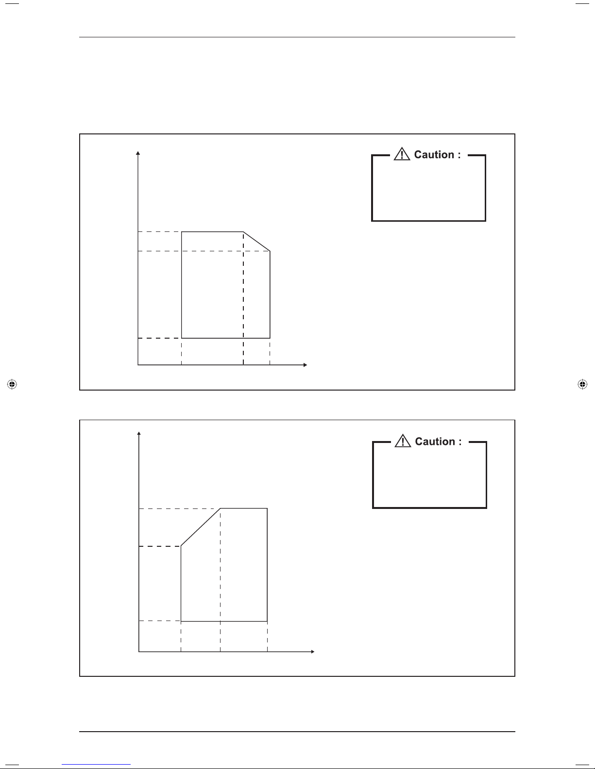
Operating Range
Ensure the operating temperature is in allowable range.
Cooling
The use of your air conditioner
outside the range of working
temperature and humidity can
result in serious failure.
Outdoor
DB (°C)
46
43
19
14 19 23 Indoor WB (°C)
Heating
The use of your air conditioner
outside the range of working
temperature and humidity can
result in serious failure.
Outdoor
WB (°C)
18
15 20 27 Indoor DB (°C)
10
-9
5
Application Information
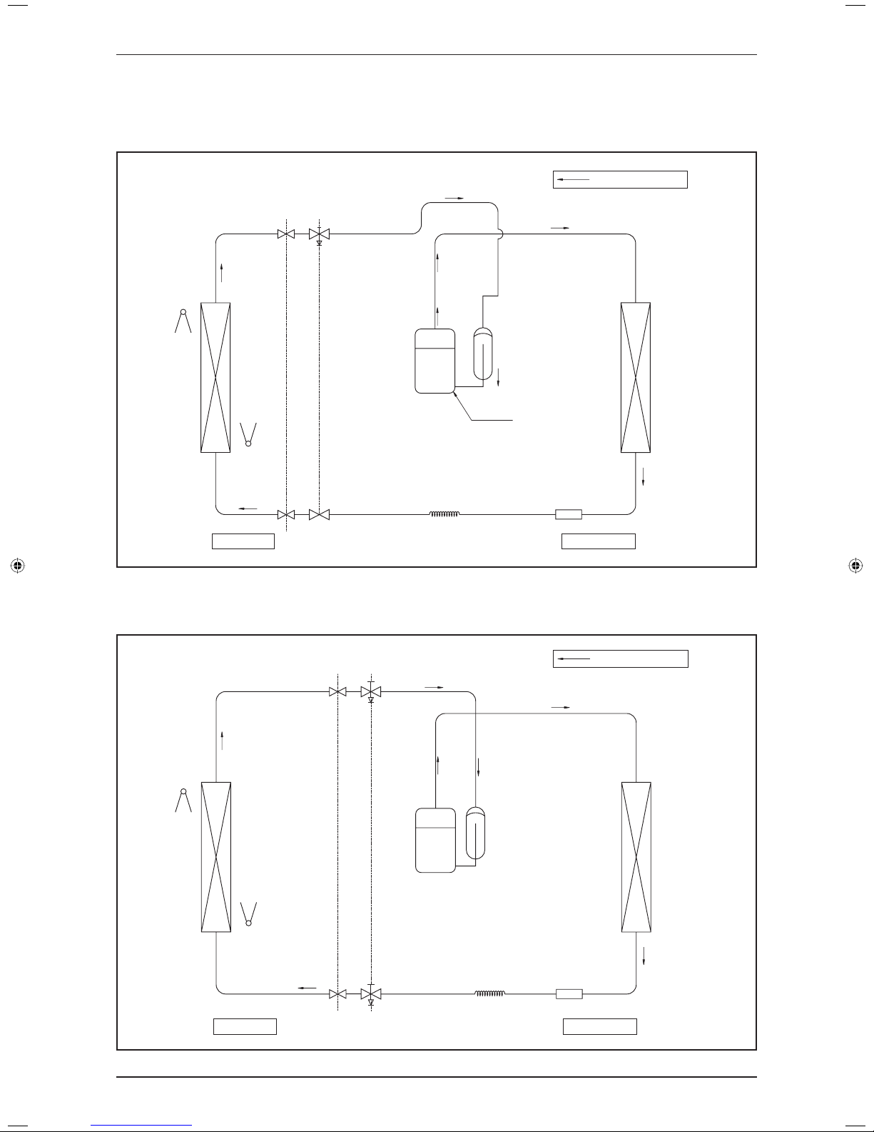
Refrigerant Circuit Diagrams
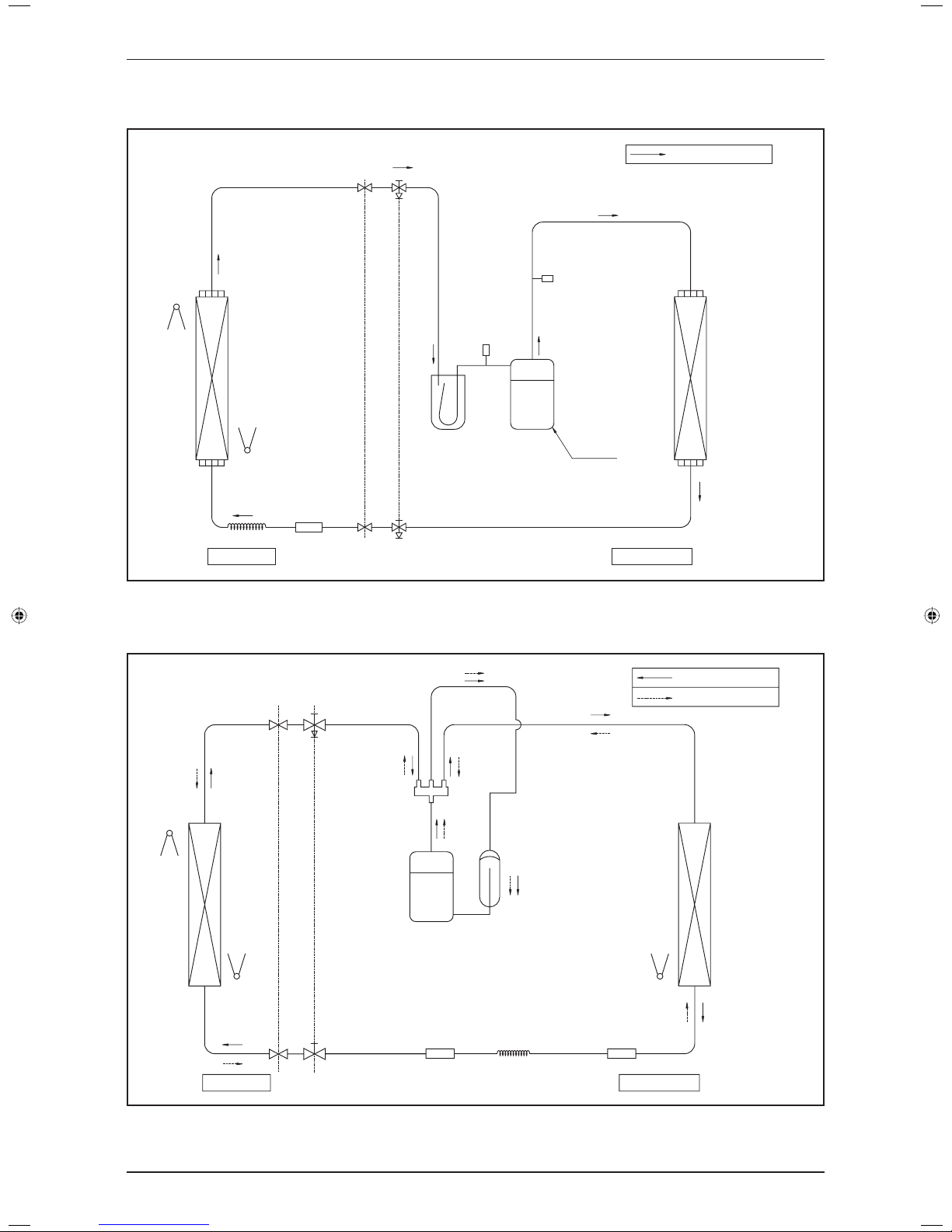
Model: FDM10/15CXV1 – R10/15CXV1 / FDM20CXV1 – R20CXV1
FDB10/15CXV1 – R10/15CXV1 / FDB20CXV1 – R20CXV1
COOLING OPERATION
3 WAY
VALVE
DISCHARGE
ACCUMULATOR
COMPRESSOR
RETURN
AIR SENSOR
HEAT EXCHANGER
(INDOOR UNIT)
PIPE TEMPERATURE
SENSOR
2 WAY
VALVE
COOLING
CAP TUBE
STRAINER
HEAT EXCHANGER
(OUTDOOR UNIT)
INDOOR UNIT OUTDOOR UNIT
Model: FDM25CXV1 – R25CXV1
FDB25CXV1 – R25CXV1
COOLING OPERATION
INDOOR UNIT OUTDOOR UNIT
RETURN
AIR SENSOR
HEAT EXCHANGER
(INDOOR UNIT)
PIPE TEMPERATURE
SENSOR
3 WAY
VALVE
DISCHARGE
ACCUMULATOR
COMPRESSOR
3 WAY
VALVE
COOLING
CAP TUBE
STRAINER
HEAT EXCHANGER
(OUTDOOR UNIT)
6
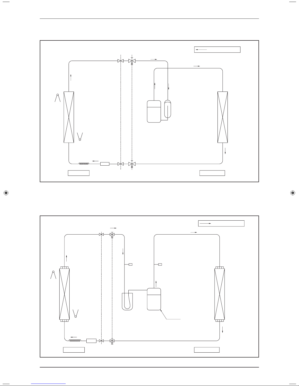
Application Information
Model: FDM28CXV1 – R28CXV1 / FDM30CXV1 – R28CXV1
FDB30CXV1 – R28CXV1
COOLING OPERATION
INDOOR UNIT OUTDOOR UNIT
RETURN
AIR SENSOR
HEAT EXCHANGER
(INDOOR UNIT)
PIPE TEMPERATURE
SENSOR
DISCHARGE
ACCUMULATOR
COMPRESSOR
3 WAY
VALVE
3 WAY
VALVE
COOLING
CAP TUBE
STRAINER
HEAT EXCHANGER
(OUTDOOR UNIT)
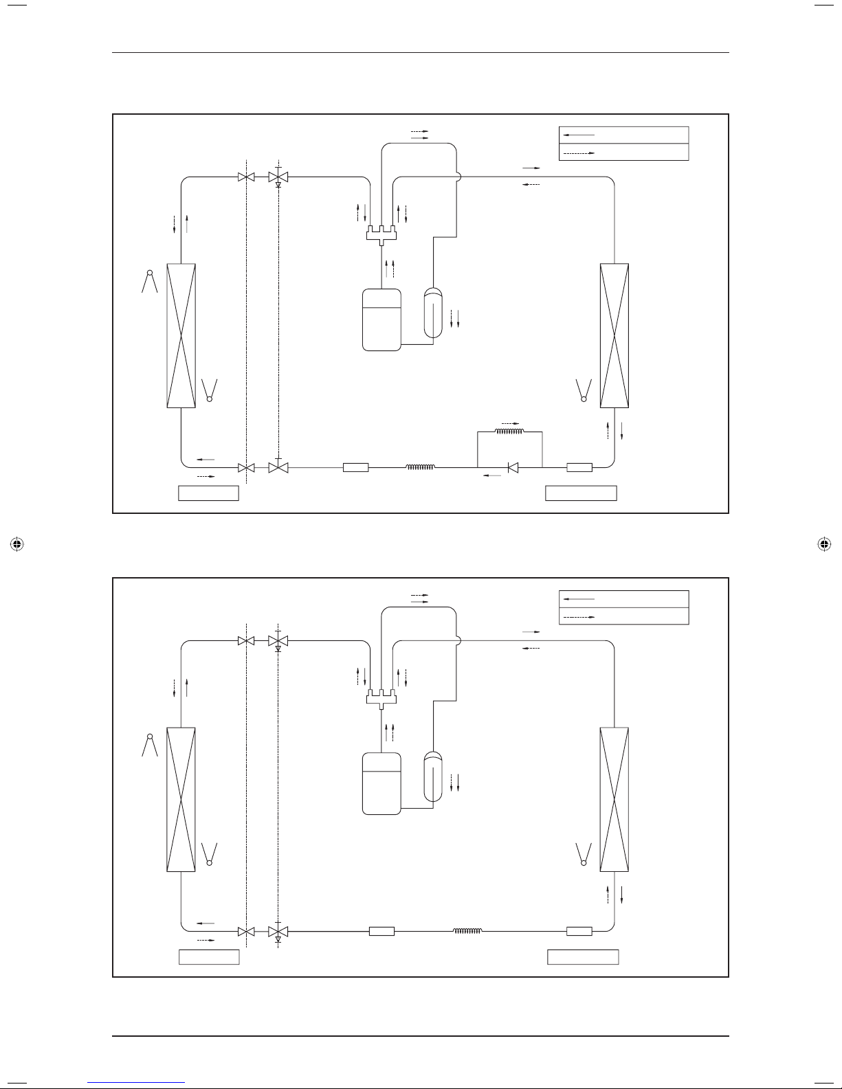
Model: FDM28/30CXV1 – R30DXV1 / FDM30CXV1 – R30DXY1 / FDM38/40CXV1 – R35/40DXV1 /
FDM38/40CXV1 – R40DXY1 / FDM50CXV1 – R50DXY1
FDB30CXV1 – R30DXV1 / FDB30CXV1 – R30DXY1 / FDB40CXV1 – R35/40DXV1 /
FDB40CXV1 – R40DXY1 / FDB50CXV1 – R50DXY1
COOLING OPERATION
INDOOR UNIT OUTDOOR UNIT
DISCHARGE
ACCUMULATOR
LOW
PRESSURE
SWITCH
HIGH
PRESSURE
SWITCH
3 WAY
VALVE
3 WAY
VALVE
RETURN
AIR SENSOR
HEAT EXCHANGER
(INDOOR UNIT)
PIPE TEMPERATURE
SENSOR
CAP TUBE
STRAINER
HEAT EXCHANGER
(OUTDOOR UNIT)
COMPRESSOR
7
Application Information
Model: FDM60CXV1 – R61DXY1
FDB60CXV1 – R61DXY1
COOLING OPERATION
INDOOR UNIT OUTDOOR UNIT
ACCUMULATOR
LOW
PRESSURE
SWITCH
HIGH
PRESSURE
SWITCH
3 WAY
VALVE
RETURN
AIR SENSOR
HEAT EXCHANGER
(INDOOR UNIT)
PIPE TEMPERATURE
SENSOR
CAP TUBE
STRAINER
HEAT EXCHANGER
(OUTDOOR UNIT)
DISCHARGE
COMPRESSOR
3 WAY
VALVE
Model: FDYM10CXV1 – RY10CXV1 / FDYM20CXV1 – RY18CXV1
FDYB10CXV1 – RY10CXV1 / FDYB20CXV1 – RY18CXV1
COOLING OPERATION
HEATING OPERATION
OUTDOOR UNITINDOOR UNIT
PIPE TEMPERATURE
SENSOR
COOLING & HEATING
CAP TUBE
STRAINER STRAINER
HEAT EXCHANGER
(OUTDOOR UNIT)
RETURN
AIR SENSOR
HEAT EXCHANGER
(INDOOR UNIT)
PIPE TEMPERATURE
SENSOR
3 WAY
VALVE
PIPING
GAS
PIPING
LIQUID
2 WAY
VALVE
DISCHARGE
4 WAY VALVE
ACCUMULATOR
COMPRESSOR
8
Application Information
Model: FDYM15CXV1 – RY15CXV1 / FDYM20CXV1 – RY20CXV1
FDYB15CXV1 – RY15CXV1 / FDYB20CXV1 – RY20CXV1
COOLING OPERATION
HEATING OPERATION
INDOOR UNIT OUTDOOR UNIT
RETURN
AIR SENSOR
HEAT EXCHANGER
(INDOOR UNIT)
PIPE TEMPERATURE
SENSOR
PIPE TEMPERATURE
SENSOR
COOLING & HEATING
CAP TUBE
STRAINER STRAINER
HEAT EXCHANGER
(OUTDOOR UNIT)
HEATING CAP
TUBE
CHECK
VALVE
3 WAY
VALVE
PIPING
GAS
PIPING
LIQUID
2 WAY
VALVE
DISCHARGE
4 WAY VALVE
ACCUMULATOR
COMPRESSOR
Model: FDYM25CXV1 – RY25CXV1 / FDYM28/30CXV1 – RY28CXV1
FDYB25CXV1 – RY25CXV1 / FDYB30CXV1 – RY28CXV1
COOLING OPERATION
HEATING OPERATION
OUTDOOR UNITINDOOR UNIT
PIPE TEMPERATURE
SENSOR
COOLING & HEATING
CAP TUBE
STRAINER STRAINER
HEAT EXCHANGER
(OUTDOOR UNIT)
RETURN
AIR SENSOR
HEAT EXCHANGER
(INDOOR UNIT)
PIPE TEMPERATURE
SENSOR
3 WAY
VALVE
PIPING
GAS
PIPING
LIQUID
3 WAY
VALVE
DISCHARGE
4 WAY VALVE
ACCUMULATOR
COMPRESSOR
9
Application Information
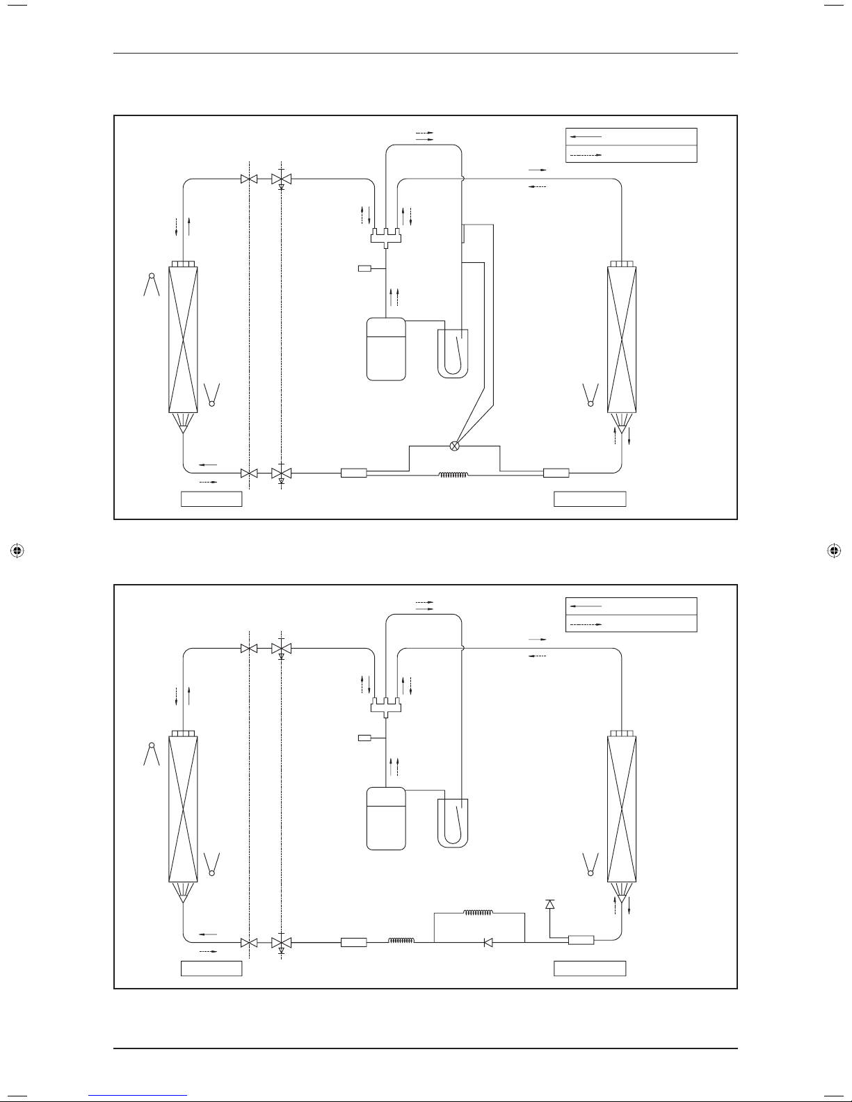
Model: FDYM28/30CXV1 – RY30DXV1 / FDYM28/30CXV1 – RY30DXY1 / FDYM38/40CXV1 – RY35DXV1
FDYB30CXV1 – RY30DXV1 / FDYB30CXV1 – RY30DXY1 / FDYB40CXV1 – RY35DXV1
COOLING OPERATION
HEATING OPERATION
OUTDOOR UNITINDOOR UNIT
PIPE TEMPERATURE
SENSOR
COOLING & HEATING
CAP TUBE
STRAINER
BIFLOW
TXV
STRAINER
HEAT EXCHANGER
(OUTDOOR UNIT)
RETURN
AIR SENSOR
HEAT EXCHANGER
(INDOOR UNIT)
PIPE TEMPERATURE
SENSOR
3 WAY
VALVE
PIPING
GAS
PIPING
LIQUID
DISCHARGE
4 WAY VALVE
HIGH
PRESSURE
SWITCH
ACCUMULATOR
COMPRESSOR
3 WAY
VALVE
Model: FDYM38/40CXV1 – RY40DXV1 / FDYM38/40CXV1 – RY40DXY1 / FDYM50CXV1 – RY50DXY1
FDYB40CXV1 – RY40DXV1 / FDYB40CXV1 – RY40DXY1 / FDYB50CXV1 – RY50DXY1
ACCUMULATOR
COOLING OPERATION
HEATING OPERATION
OUTDOOR UNITINDOOR UNIT
PIPE TEMPERATURE
SENSOR
HEATING CAP. TUBE
ACCESS
VALVE
STRAINER
COOLING
CAP. TUBE
CHECK
VALVE
STRAINER
HEAT EXCHANGER
(OUTDOOR UNIT)
RETURN
AIR SENSOR
HEAT EXCHANGER
(INDOOR UNIT)
PIPE TEMPERATURE
SENSOR
3 WAY
VALVE
PIPING
GAS
PIPING
LIQUID
3 WAY
VALVE
DISCHARGE
4 WAY VALVE
HIGH
PRESSURE
SWITCH
COMPRESSOR
10
Application Information
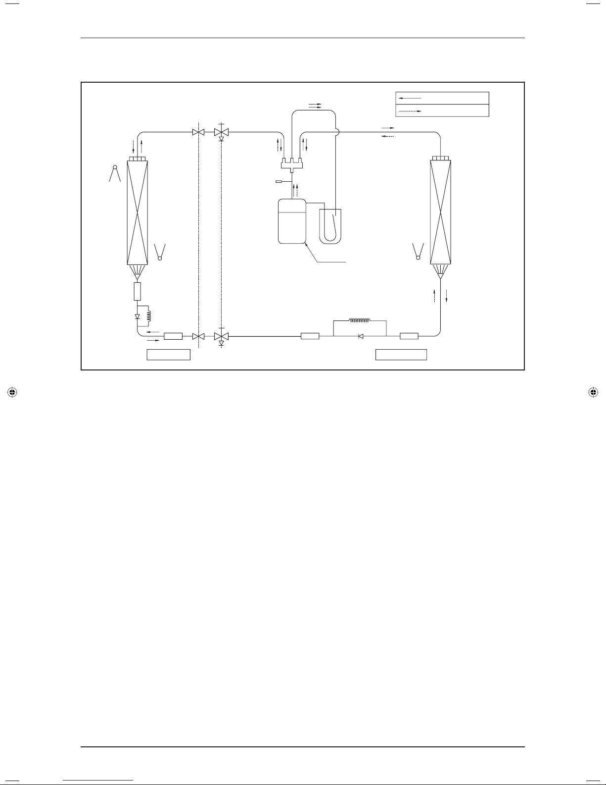
Model: FDYM60CXV1 – RY61DXY1
FDYB60CXV1 – RY61DXY1
COOLING OPERATION
HEATING OPERATION
OUTDOOR UNITINDOOR UNIT
PIPE TEMPERATURE
SENSOR
HEATING CAP. TUBE
STRAINER
CHECK VALVE
STRAINER
HEAT EXCHANGER
(OUTDOOR UNIT)
RETURN
AIR SENSOR
HEAT EXCHANGER
(INDOOR UNIT)
PIPE TEMPERATURE
SENSOR
3 WAY VALVE
PIPING
GAS
PIPING
LIQUID
3 WAY
VALVE
DISCHARGE
STRAINER
STRAINER
CHECK
VALVE
COOLING
CAP. TUBE
4 WAY VALVE
HIGH PRESSURE
SWITCH
ACCUMULATOR
COMPRESSOR
11
Application Information
Installation Guideline
Sharp edges and coil surfaces are potential injury hazard. Avoid from contact with them.
(1) Installation of Indoor Unit
Preliminary Survey
Electrical supply and installation is to confi rm to local authority’s (e.g. National Electrical Board) codes and
regulations.
Voltage supply fl uctuation must not exceed ± 10% of rated voltage. Electricity supply lines must be
independent of welding transformers which can cause high supply fl uctuation.
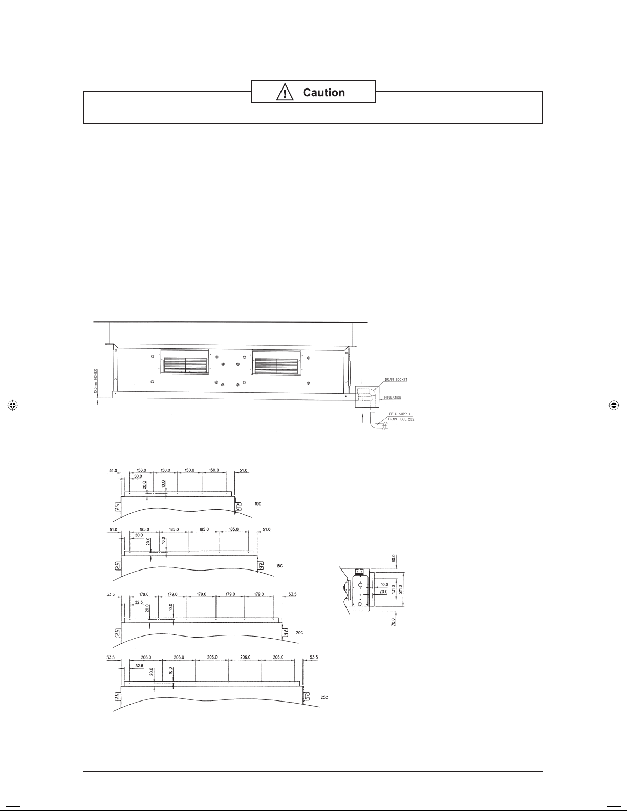
Ensure that the location is convenient for wiring, piping and drainage.
The indoor unit must be installed in such that free from any obstacles in path of cool air discharge and
warm air return, and must allow spreading or air throughout the room (near the centre of the room).
Clearance must be provided for the indoor unit from the wall and obstacles as shown in the fi gure.
Use the hanger supplied with the unit.
Ensure the support is strong enough to withstand the weight of the unit.
Use the supplied drain socket to connect the drain pipe (the drain socket is only available for
FD(Y)M10CXV1 / FD(Y)B10CXV1 to FD(Y)M25CXV1 / FD(Y)B25CXV1)
Install the unit in such a way that
the condensate water can flow
out smoothly.
The diagrams below show the screws position for duct work connection.
•
•
•
•
•
•
•
•
12
Application Information
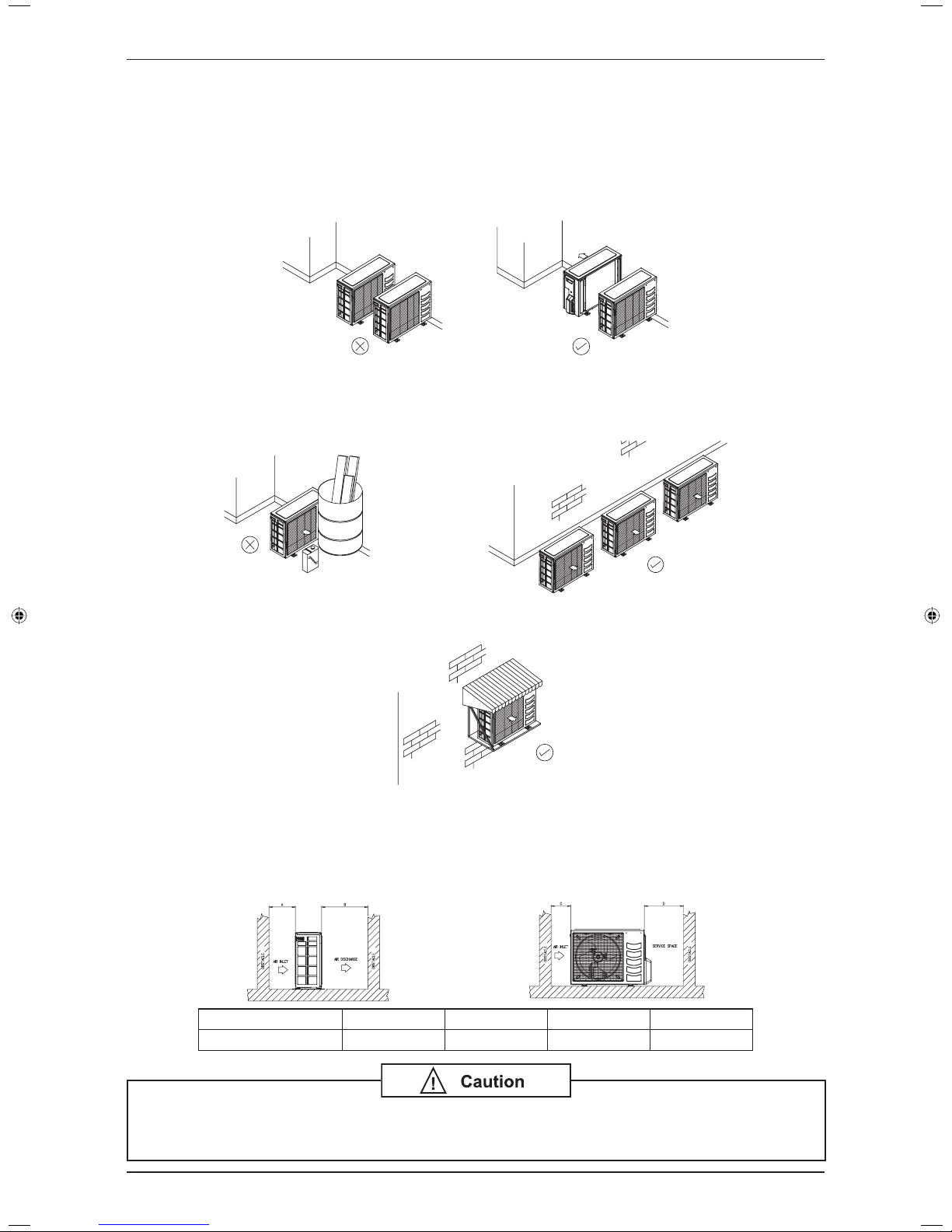
(2) Installation of Outdoor Unit
As condensing temperature rises, evaporating temperature rises and cooling capacity drops. In order to achieve
maximum cooling capacity, the location selected for outdoor unit should fulfi ll the following requirements:
Install the condensing (outdoor) unit in a way such that hot air distributed by the outdoor condensing unit
cannot be drawn in again (as in the case of short circuit of hot discharge air). Allow suffi cient space for
maintenance around the unit.
Ensure that there is no obstruction of air fl ow into or out of the unit. Remove obstacles which block air
intake or discharge.
The location must be well ventilated, so that the unit can draw in and distribute plenty of air thus lowering
the condensing temperature.
A place capable of bearing the weight of the outdoor unit and isolating noise and vibration.
A place protected from direct sunlight. Otherwise use an awning for protection, if necessary.
The location must not be susceptible to dust or oil mist.
Installation Clearance
Outdoor units must be installed such that there is no short circuit of the hot discharge air or obstruction to
smooth air fl ow. Select the coolest possible place where intake air should not be hotter than the outside
temperature (max. 45˚C).
ALL MODEL A B C D
Minimum Distance 300 mm 1000 mm 300 mm 500 mm
If the condensing unit is operated in an atmosphere containing oils (including machine oils), salt
(coastal area), sulphide gas (near hot spring, oil refi nery plant), such substances may lead to
failure of the unit.
•
•
•
•
•
•
•

13
Application Information
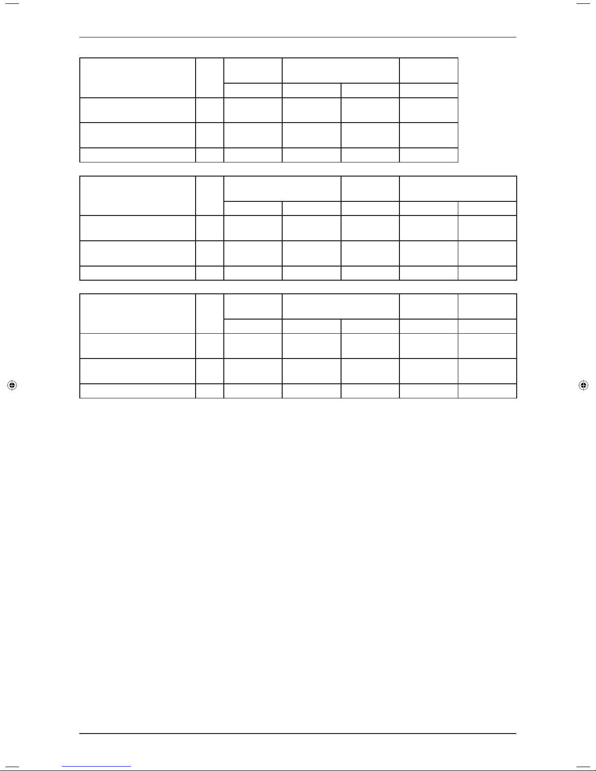
(3) Cable Size
Model Unit
FDM10CXV1
FDB10CXV1
FDM15CXV1
FDB15CXV1
FDM20CXV1
FDB20CXV1
FDM25CXV1
FDB25CXV1
FDM28CXV1
R10CXV1 R15CXV1 R20CXV1 R25CXV1 R28CXV1
Power supply cable size
Number of wire
mm
2
1.5
3
1.5
3
2.5
3
2.5
3
2.5
3
Interconnection cable size
Number of wire
mm
2
1.5
3
1.5
3
2.5
3
2.5
3
2.5
3
Recommended fuse A 10 10 16 20 20
Model Unit
FDM28CXV1
FDM30CXV1
FDB30CXV1
FDM38CXV1
R30DXV1 R28CXV1 R30DXV1 R30DXY1 R35DXV1
Power supply cable size
Number of wire
mm
2
4.0
3
2.5
3
4.0
3
1.5
5
4.0
3
Interconnection cable size
Number of wire
mm
2
2.5
4
2.5
3
2.5
4
1.5
4
2.5
4
Recommended fuse A 25 20 25 10 25
Model Unit
FDM38CXV1
FDM40CXV1
FDB40CXV1
FDM40CXV1
FDB40CXV1
R40DXV1 R40DXY1 R35DXV1 R40DXV1 R40DXY1
Power supply cable size
Number of wire
mm
2
4.0
3
1.5
5
4.0
3
4.0
3
1.5
5
Interconnection cable size
Number of wire
mm
2
2.5
4
1.5
4
2.5
4
2.5
4
1.5
4
Recommended fuse A 25 10 25 25 10
Model Unit
FDM50CXV1
FDB50CXV1
FDM60CXV1
FDB60CXV1
R50DXY1 R61DXY1
Power supply cable size
Number of wire
mm
2
2.5
5
2.5
5
Interconnection cable size
Number of wire
mm
2
2.5
4
2.5
4
Recommended fuse A 16 20
Model Unit
FDYM10CXV1
FDYB10CXV1
FDYM15CXV1
FDYB15CXV1
FDYM20CXV1
FDYB20CXV1
FDYM20CXV1
FDYB20CXV1
FDYM25CXV1
FDYB25CXV1
RY10CXV1 RY15CXV1 RY18CXV1 RY20CXV1 RY25CXV1
Power supply cable size
Number of wire
mm
2
1.5
3
1.5
3
2.5
3
2.5
3
2.5
3
Interconnection cable size
Number of wire
mm
2
1.5
5
1.5
5
2.5
5
2.5
5
2.5
5
Recommended fuse A 10 10 16 16 20
14
Application Information
Model Unit
FDYM28CXV1 FDYM28CXV1
FDYM30CXV1
FDYB30CXV1
RY28CXV1 RY30DXV1 RY30DXY1 RY28CXV1
Power supply cable size
Number of wire
mm
2
2.5
3
4.0
3
1.5
5
2.5
3
Interconnection cable size
Number of wire
mm
2
2.5
5
2.5
4 & 3
1.5
4 & 3
2.5
5
Recommended fuse A 20 25 10 20
Model Unit
FDYM30CXV1
FDYB30CXV1
FDYM38CXV1 FDYM38CXV1
RY30DXV1 RY30DXY1 RY35DXV1 RY40DXV1 RY40DXY1
Power supply cable size
Number of wire
mm
2
4.0
3
1.5
5
4.0
3
4.0
3
1.5
5
Interconnection cable size
Number of wire
mm
2
2.5
4 & 3
1.5
4 & 3
2.5
4 & 3
2.5
4 & 3
1.5
4 & 3
Recommended fuse A 25 10 25 25 10
Model Unit
FDYM40CXV1
FDYB40CXV1
FDYM40CXV1
FDYB40CXV1
FDYM50CXV1
FDYB50CXV1
FDYM60CXV1
FDYB60CXV1
RY35DXV1 RY40DXV1 RY40DXY1 RY50DXY1 RY61DXY1
Power supply cable size
Number of wire
mm
2
4.0
3
4.0
3
1.5
5
2.5
5
2.5
5
Interconnection cable size
Number of wire
mm
2
2.5
4 & 3
2.5
4 & 3
1.5
4 & 3
1.5
4 & 3
1.5
4 & 3
Recommended fuse A 25 25 10 16 16
15
Application Information
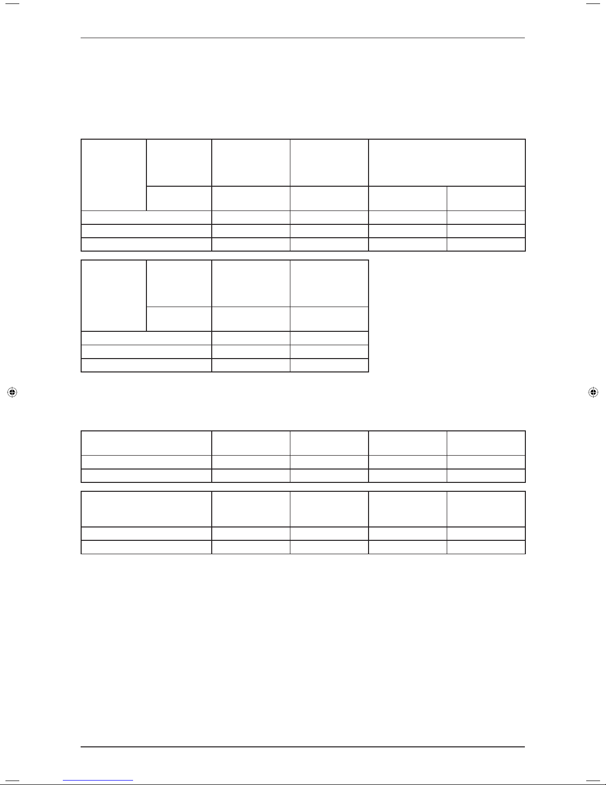
(4) Refrigerant Piping
Maximum Pipe and Maximum Number of Bends
When the pipe length becomes too long, both the capacity and reliability drop. As the number of bends
increases, system piping resistance to the refrigerant fl ow increases, thus lowering the cooling capacity,
and as the result the font compressor may become defective. Always choose the shortest path and follow
the recommendation as tabulated below:
Model
Indoor
FDM10/15CXV1
FDYM10/15CXV1
FDB10/15CXV1
FDYB10/15CXV1
FDM20/25CXV1
FDYM20/25CXV1
FDB20/25CXV1
FDYB20/25CXV1
FDM28/30CXV1
FDYM28/30CXV1
FDB30CXV1
FDYB30CXV1
Outdoor
R(Y)10/15CXV1 R(Y)20/25CXV1 R(Y)28CXV1
R(Y)30DXV1 /
R(Y)30DXY1
Max. Length, m 12 15 15 45
Max. Elevation, m 5 8 8 25
Max. No. of Bends 10 10 10 10
Model
Indoor
FDM38/40/50CXV1
FDYM38/40/50CXV1
FDB40/50CXV1
FDYB40/50CXV1
FDM60CXV1
FDYM60CXV1
FDB60CXV1
FDYB60CXV1
Outdoor
R(Y)35/40DXV1
R(Y)40/50DXY1
R(Y)61DXY1
Max. Length, m 45 35
Max. Elevation, m 25 15
Max. No. of Bends 10 10
Piping Sizes (Flare connection type)
Piping sizes are as follows:
R22
Model R(Y)10CXV1 R(Y)15CXV1
R20CXV1 /
RY18/20CXV1
R(Y)25CXV1
Liquid, mm / in 6.35 / 1/4 6.35 / 1/4 6.35 / 1/4 9.52 / 3/8
Suction, mm / in 9.52 / 3/8 12.70 / 1/2 15.88 / 5/8 15.88 / 5/8
Model
R(Y)28CXV1 /
R(Y)30DXV1 /
R(Y)30DXY1
R(Y)35/40DXV1 /
R(Y)40DXY1
R(Y)50DXY1 R(Y)61DXY1
Liquid, mm / in 9.52 / 3/8 9.52 / 3/8 9.52 / 3/8 12.70 / 1/2
Suction, mm / in 15.88 / 5/8 19.05 / 3/4 19.05 / 3/4 19.05 / 3/4
•
16
Application Information
(5) Additional Charge
The refrigerant charge has already charged into the outdoor unit. For the piping length of 7.6m, additional
refrigerant charge after vacuuming is not necessary.
When the piping length is more than 7.6m, please use the table below (unit in gram).
R22 – Cooling Only
Indoor
FDM10CXV1
FDB10CXV1
FDM15CXV1
FDB15CXV1
FDM20CXV1
FDB20CXV1
FDM25CXV1
FDB25CXV1
FDM28CXV1
Outdoor R10CXV1 R15CXV1 R20CXV1 R25CXV1 R28CXV1
Add. Charge, g/m 16 16 16 39 41
Indoor FDM28CXV1
FDM30CXV1
FDB30CXV1
FDM30CXV1
FDB30CXV1
FDM38CXV1
Outdoor R30DXV1 R28CXV1 R30DXV1 R30DXY1 R35DXV1
Add. Charge, g/m 56 41 41 55 54
Indoor FDM38CXV1
FDM40CXV1
FDB40CXV1
FDM40CXV1
FDB40CXV1
Outdoor R40DXV1 R40DXY1 R35DXV1 R40DXV1 R40DXY1
Add. Charge, g/m 40 41 54 55
Indoor
FDM50CXV1
FDB50CXV1
FDM60CXV1
FDB60CXV1
Outdoor R50DXY1 R61DXY1
Add. Charge, g/m 54 102
R22 – Heatpump
Indoor
FDYM10CXV1
FDYB10CXV1
FDYM15CXV1
FDYB15CXV1
FDYM20CXV1
FDYB20CXV1
FDYM20CXV1
FDYB20CXV1
FDYM25CXV1
FDYB25CXV1
Outdoor RY10CXV1 R15CXV1 RY18CXV1 RY20CXV1 RY25CXV1
Add. Charge, g/m 22 22 16 16 40
Indoor FDYM28CXV1 FDYM28CXV1
FDYM30CXV1
FDYB30CXV1
Outdoor RY28CXV1 RY30DXV1 RY30DXY1 RY28CXV1
Add. Charge, g/m 41 41 41
Indoor
FDYM30CXV1
FDYB30CXV1
FDYM38CXV1 FDYM38CXV1
Outdoor RY30DXV1 RY30DXY1 RY35DXV1 RY40DXV1 RY40DXY1
Add. Charge, g/m 55 41 57 57
Indoor
FDYM40CXV1
FDYB40CXV1
FDYM40CXV1
FDYB40CXV1
FDYM50CXV1
FDYB50CXV1
FDYM60CXV1
FDYB60CXV1
Outdoor RY35DXV1 RY40DXV1 RY40DXY1 RY50DXY1 RY61DXY1
Add. Charge, g/m 57 55 41 56 106
The additional refrigerant charge amount recommended is a guideline for longer piping application. The
actual charge required may be different from the guideline due to different application and variation in site
conditions.
•
•
17
Sound Data
Sound Data
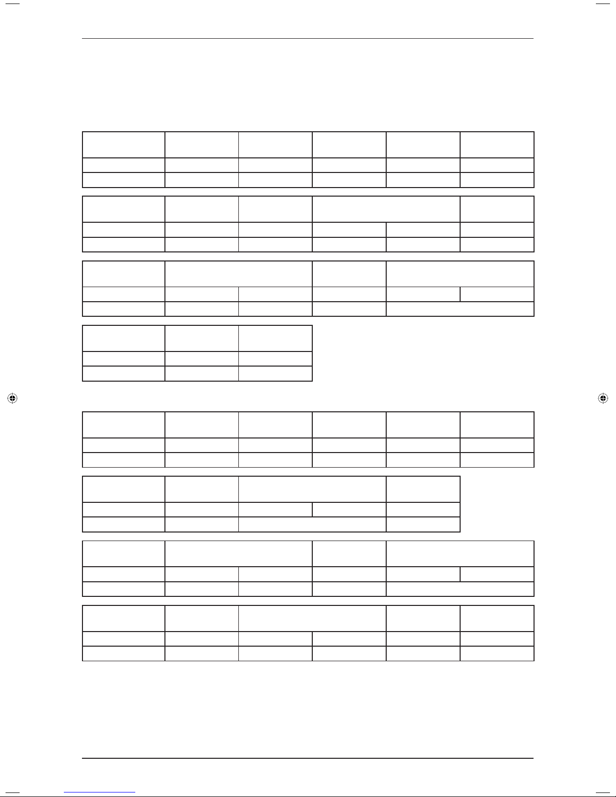
Sound Pressure Level
Model Speed
1/1 Octave Sound Pressure (dB, ref 20μPa)
Overall
(dBA)
Noise
Criteria
125Hz 250Hz 500Hz 1kHz 2kHz 4kHz 8kHz
FD(Y)M10CXV1
High
43 35 35 30 26 18 13 36 30
Med
43 34 34 28 25 17 12 35 29
Low
42 31 31 27 22 14 9 33 25
FD(Y)M15CXV1
High
46 40 40 33 29 21 17 40 35
Med
45 38 38 31 27 18 14 38 33
Low
40 33 33 26 21 11 9 33 28
FD(Y)M20CXV1
High
47 41 43 35 31 24 19 42 38
Med
47 41 41 34 31 23 18 41 36
Low
47 39 39 33 29 21 16 40 34
FD(Y)M25CXV1
High
48 41 40 35 31 24 19 41 35
Med
47 39 39 34 29 22 17 40 34
Low
44 35 35 30 25 17 12 36 30
FD(Y)M28CXV1
S. High 48 45 42 38 34 29 26 44 37
High 45 42 39 35 31 26 22 41 34
Med 42 38 37 32 28 22 17 38 32
Low 36 33 33 27 23 16 11 34 27
FD(Y)M30CXV1
S. High 54 50 46 45 40 34 30 49 44
High 50 45 43 42 37 31 26 46 41
Med 45 40 40 38 32 26 20 42 37
Low 42 36 37 33 28 22 15 38 32
FD(Y)M38CXV1
S. High 56 57 53 50 46 41 36 55 49
High 54 51 48 46 41 36 31 51 45
Med 51 48 46 45 37 32 26 48 44
Low 47 45 44 41 34 28 22 45 40
FD(Y)M40CXV1
S. High 56 49 49 46 41 37 32 51 45
High 54 47 47 45 39 35 29 49 44
Med 49 42 43 41 35 31 24 45 40
Low 45 39 41 37 30 26 18 41 36
FD(Y)M50CXV1
S. High 56 50 50 49 44 38 33 53 48
High 54 49 49 48 43 37 32 52 47
Med 53 47 46 47 40 35 29 50 46
Low 51 45 44 44 36 32 26 47 43
FD(Y)M60CXV1
S. High 57 50 51 51 46 39 35 55 50
High 55 49 49 50 44 37 33 53 49
Med 53 46 47 47 39 34 28 50 46
Low 51 43 44 43 35 30 24 47 42
Model Measuring location
FD(Y)M10CXV1
FD(Y)M15CXV1
FD(Y)M20CXV1
FD(Y)M25CXV1
FD(Y)M28CXV1
FD(Y)M30CXV1
FD(Y)M38CXV1
FD(Y)M40CXV1
FD(Y)M50CXV1
FD(Y)M60CXV1
FD(Y)B10CXV1
FD(Y)B15CXV1
FD(Y)B20CXV1
FD(Y)B25CXV1
FD(Y)B30CXV1
FD(Y)B40CXV1
FD(Y)B50CXV1
FD(Y)B60CXV1
18
Sound Data
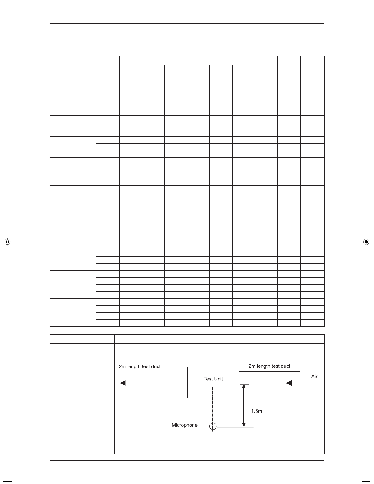
Sound Pressure Level
Model Speed
1/1 Octave Sound Pressure (dB, ref 20μPa)
Overall
(dBA)
Noise
Criteria
125Hz 250Hz 500Hz 1kHz 2kHz 4kHz 8kHz
FD(Y)B10CXV1
High
39 35 33 28 23 16 12 33 28
Med
36 29 30 25 19 12 11 30 24
Low
31 24 25 19 13 7 10 25 20
FD(Y)B15CXV1
High
42 36 36 29 25 16 9 36 31
Med
39 33 33 27 19 9 6 33 28
Low
33 27 28 19 12 6 5 28 22
FD(Y)B20CXV1
High
44 39 37 31 28 20 15 38 32
Med
43 39 36 30 27 19 14 37 31
Low
43 36 34 28 25 16 10 35 29
FD(Y)B25CXV1
High
47 38 39 34 30 23 18 40 34
Med
46 37 38 33 29 22 17 39 33
Low
42 33 34 29 24 15 10 35 29
FD(Y)B30CXV1
S. High
45 42 39 35 31 26 22 41 34
High
47 38 39 34 30 23 18 40 34
Med
46 37 38 33 29 22 17 39 33
Low
42 36 36 29 25 16 11 36 31
FD(Y)B40CXV1
S. High
47 43 42 38 35 29 24 43 37
High
45 42 39 35 31 26 22 41 34
Med
42 41 37 34 31 29 23 40 33
Low
42 38 37 32 28 22 17 38 32
FD(Y)B50CXV1
S. High
50 45 43 42 37 31 26 46 41
High
49 43 42 39 35 29 24 44 38
Med
47 43 41 38 35 27 23 43 37
Low
47 41 40 37 32 27 22 42 36
FD(Y)B60CXV1
S. High
58 46 45 44 40 33 26 48 43
High
58 45 45 43 37 31 24 47 42
Med
58 44 45 42 36 30 23 46 42
Low
56 42 43 41 35 30 23 45 40
Model Measuring location
FD(Y)M10CXV1
FD(Y)M15CXV1
FD(Y)M20CXV1
FD(Y)M25CXV1
FD(Y)M28CXV1
FD(Y)M30CXV1
FD(Y)M38CXV1
FD(Y)M40CXV1
FD(Y)M50CXV1
FD(Y)M60CXV1
FD(Y)B10CXV1
FD(Y)B15CXV1
FD(Y)B20CXV1
FD(Y)B25CXV1
FD(Y)B30CXV1
FD(Y)B40CXV1
FD(Y)B50CXV1
FD(Y)B60CXV1
19
Sound Data
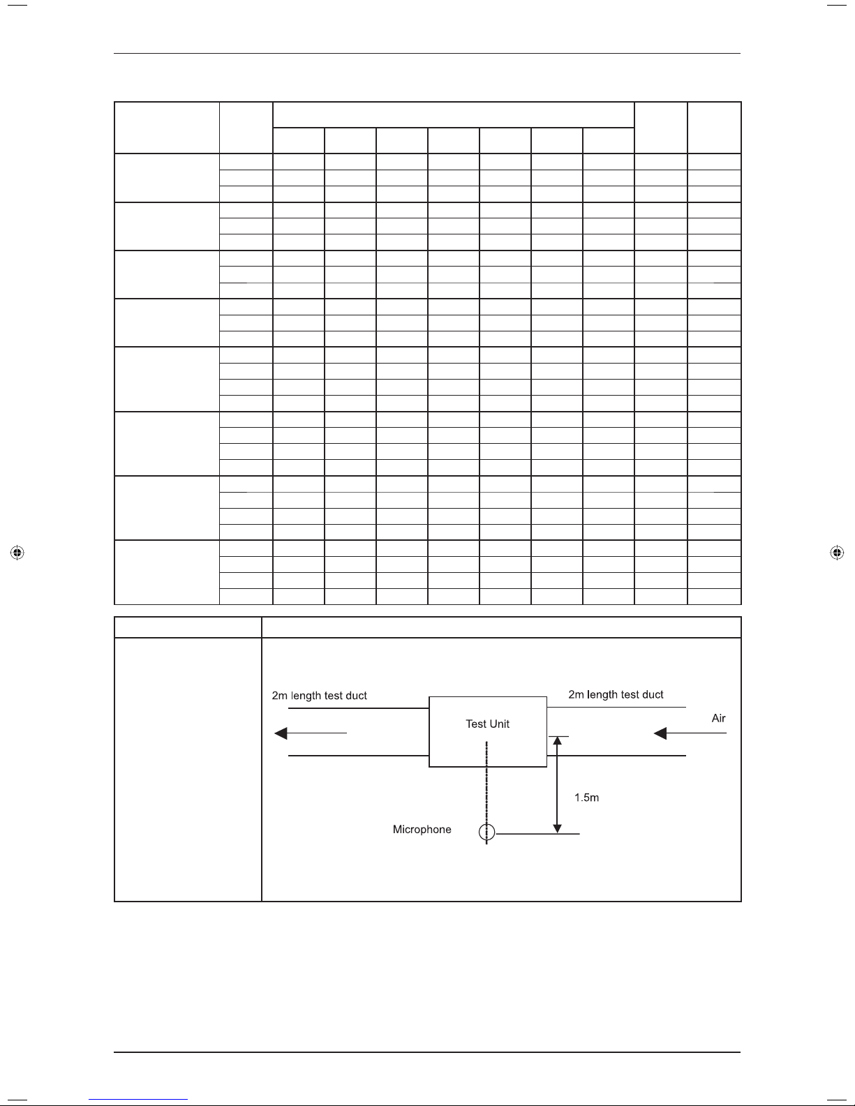
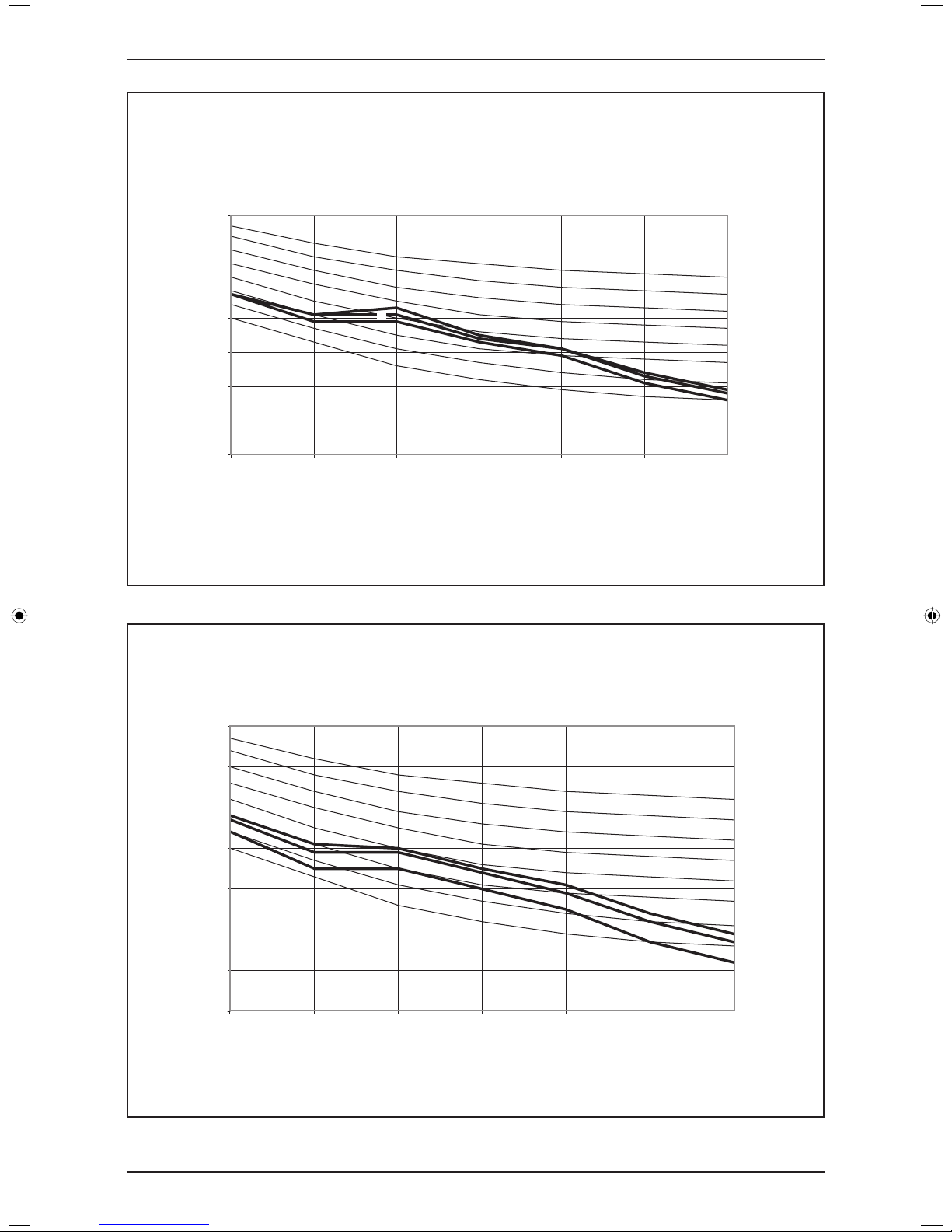
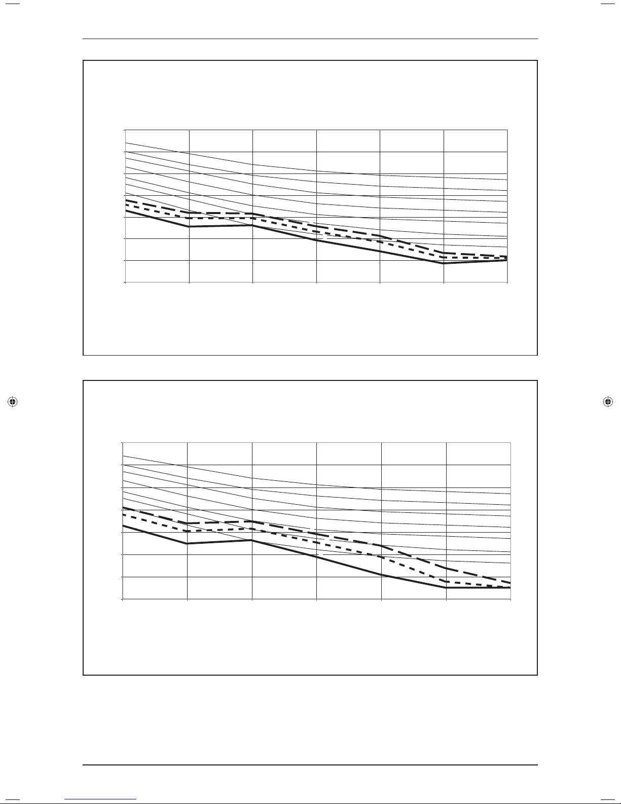
NC Curve
FD(Y)M10CXV1
0
10
20
30
40
50
60
70
125 250 500 1000 2000 4000 8000
Octave-band frequency (Hz)
Sound pressure level (dB, ref 20Pa)
NC-20
NC-30
NC-25
NC-35
NC-40
NC-45
NC-50
NC-55
H
L
M
FD(Y)M15CXV1
0
10
20
30
40
50
60
70
125 250 500 1000 2000 4000 8000
Octave-band frequency (Hz)
Sound pressure level (dB, ref 20Pa)
NC-20
NC-30
NC-25
NC-35
NC-40
NC-45
NC-50
NC-55
H
L
M
20
Sound Data
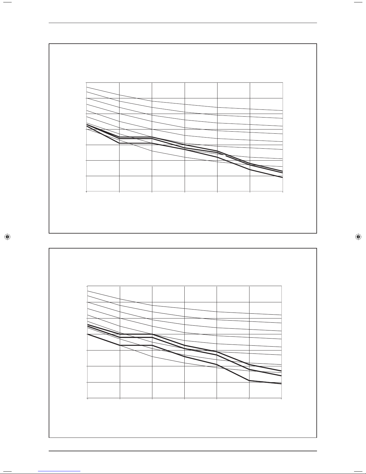
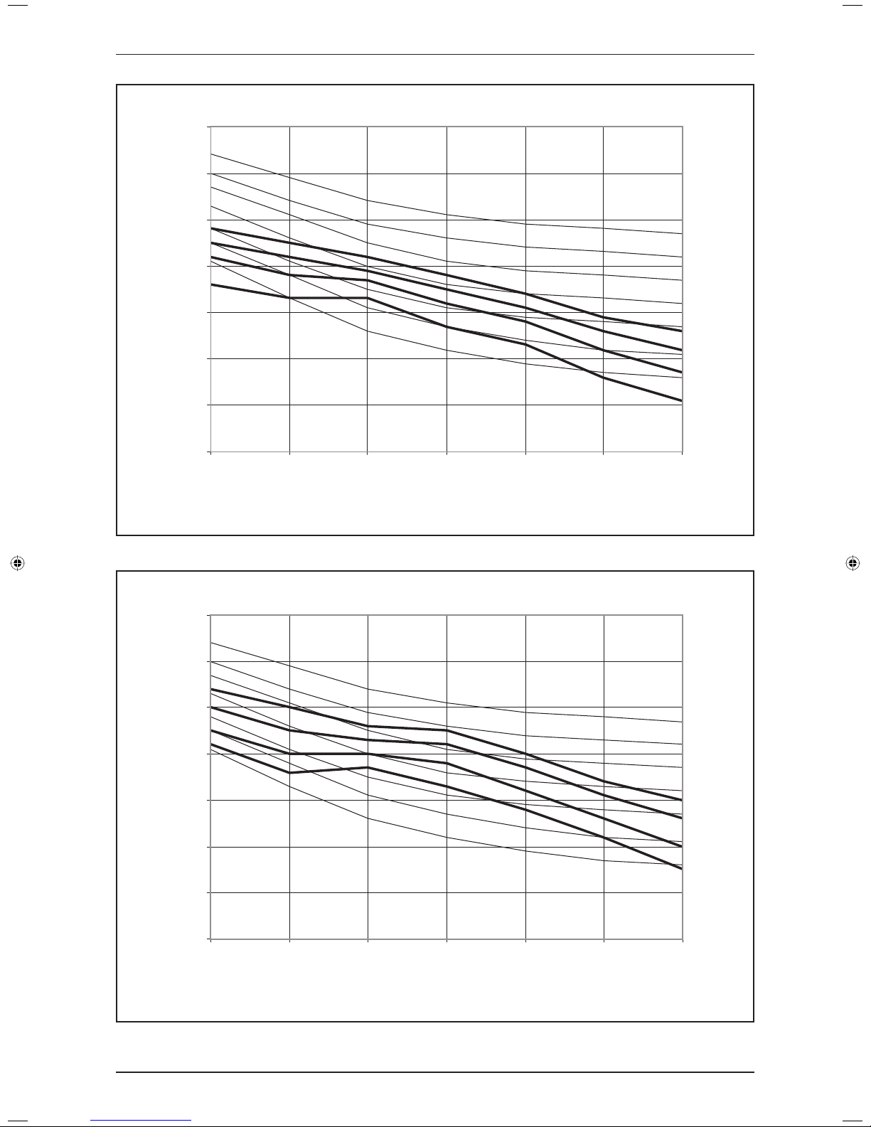
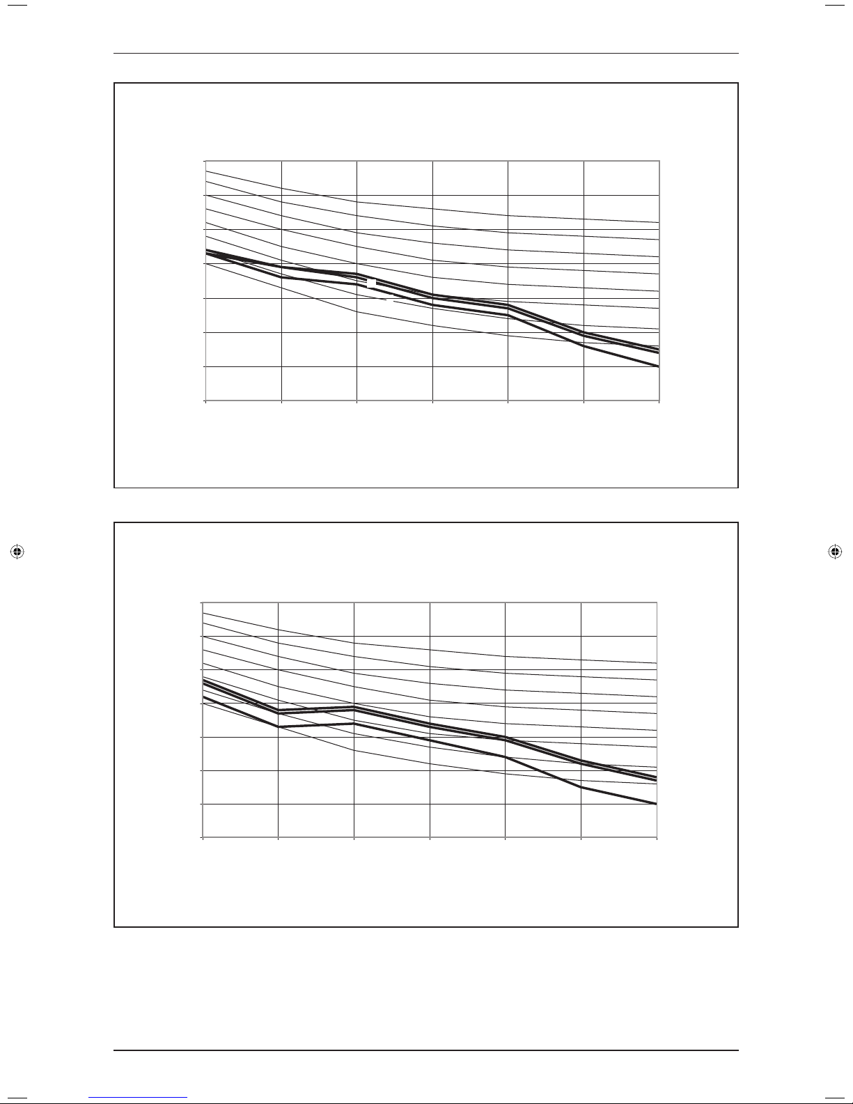
FD(Y)M20CXV1
0
10
20
30
40
50
60
70
125 250 500 1000 2000 4000 8000
Octave-band frequency (Hz)
Sound pressure level (dB, ref 20Pa)
NC-30
NC-25
NC-35
NC-40
NC-45
NC-50
NC-55
NC-20
L
H
M
FD(Y)M25CXV1
0
10
20
30
40
50
60
70
125 250 500 1000 2000 4000 8000
Octave-band frequency (Hz)
Sound pressure level (dB, ref 20Pa)
NC-20
NC-30
NC-25
NC-35
NC-40
NC-45
NC-50
NC-55
H
M
L
21
Sound Data
0
10
20
30
40
50
60
70
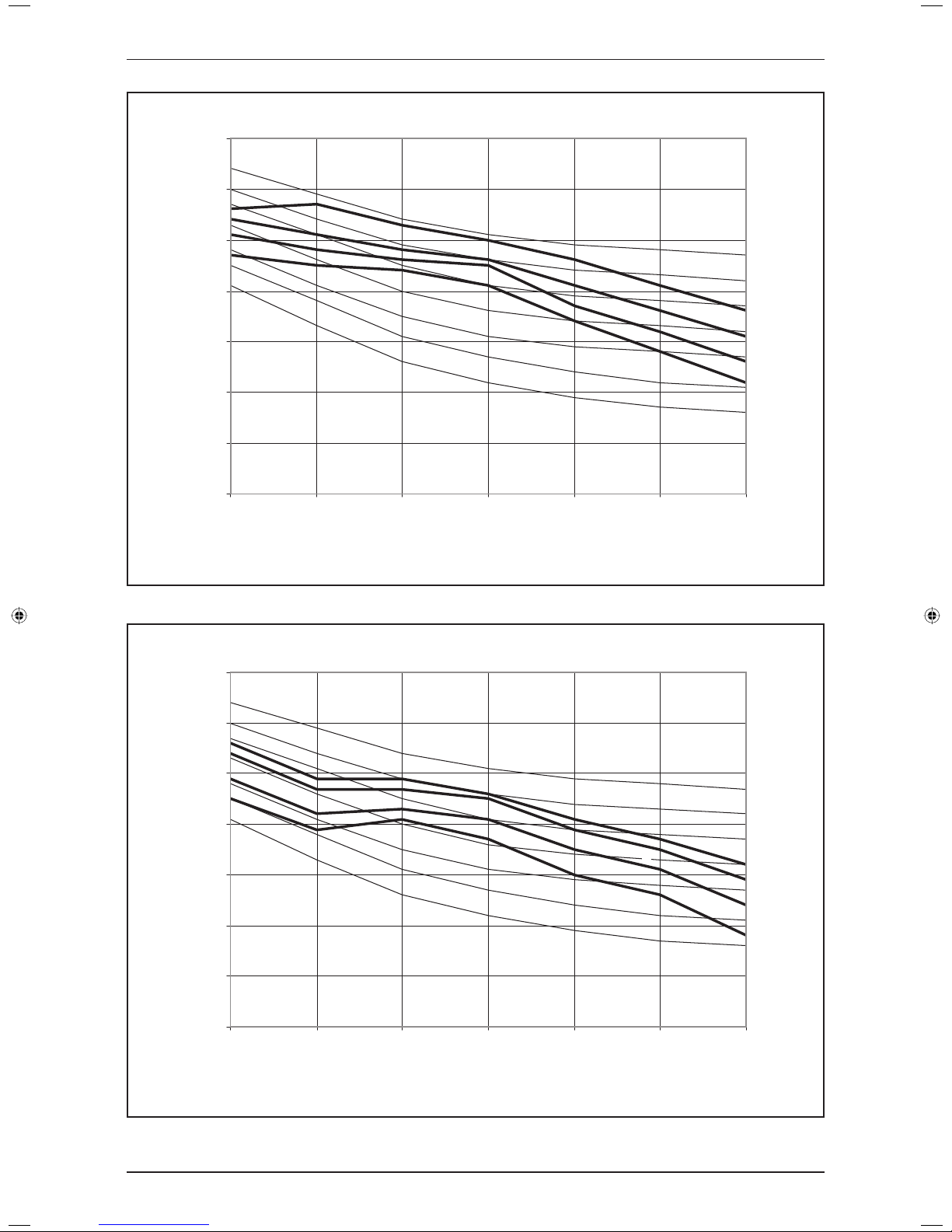
125 250 500 1000 2000 4000 8000
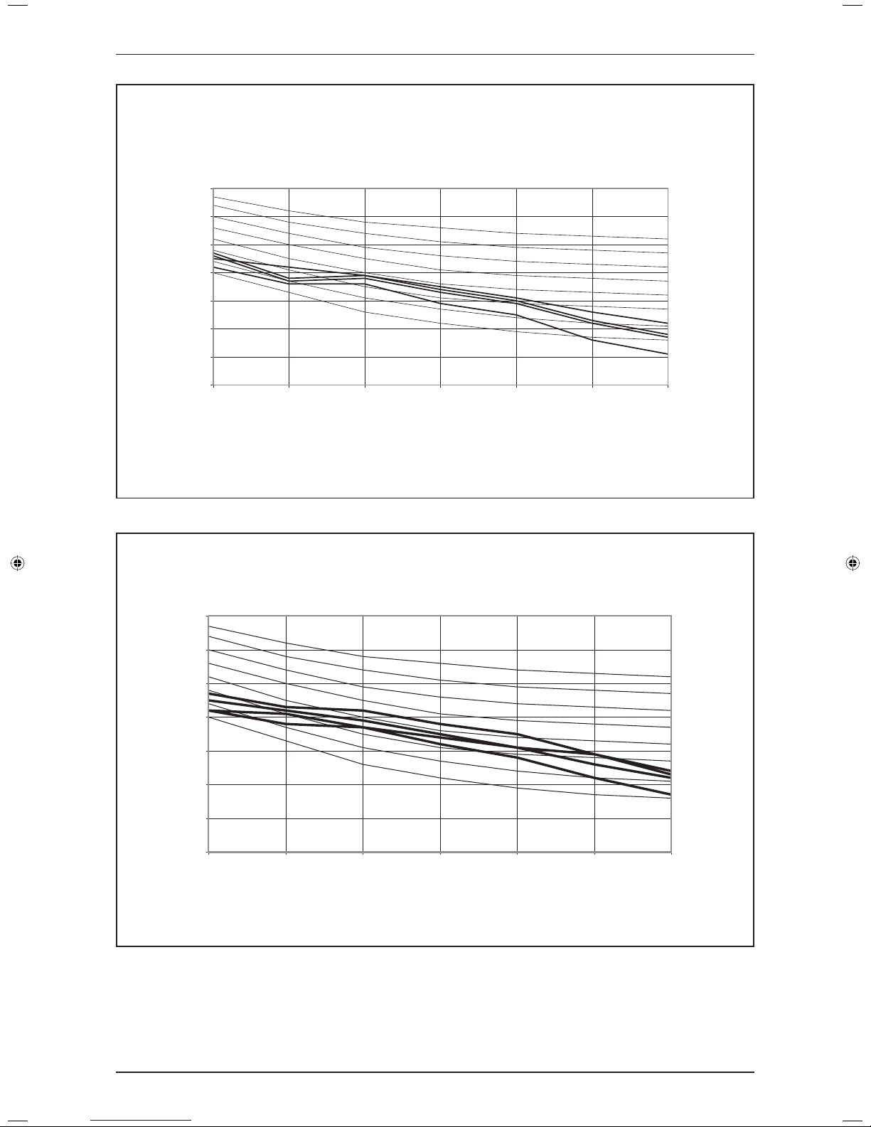
NC-40
NC-35
NC-30
NC-20
NC-45
NC-50
NC-25
Measured in anechoic room at 1.5m below the centre of the unit
Tested with 2m length duct at the air discharge outlet and air return inlet
Octave-band frequency (Hz)
Sound pressure level (dB, ref 20Pa)
FD(Y)M28CXV1
SH
H
M
L
0
10
20
30
40
50
60
70
125 250 500 1000 2000 4000 8000
NC-40
NC-35
NC-20
NC-45
NC-50
NC-30
NC-25
Measured in anechoic room at 1.5m below the centre of the unit
Tested with 2m length duct at the air discharge outlet and air return inlet
Octave-band frequency (Hz)
Sound pressure level (dB, ref 20Pa)
FD(Y)M30CXV1
SH
H
M
L
22
Sound Data
0
10
20
30
40
50
60
70
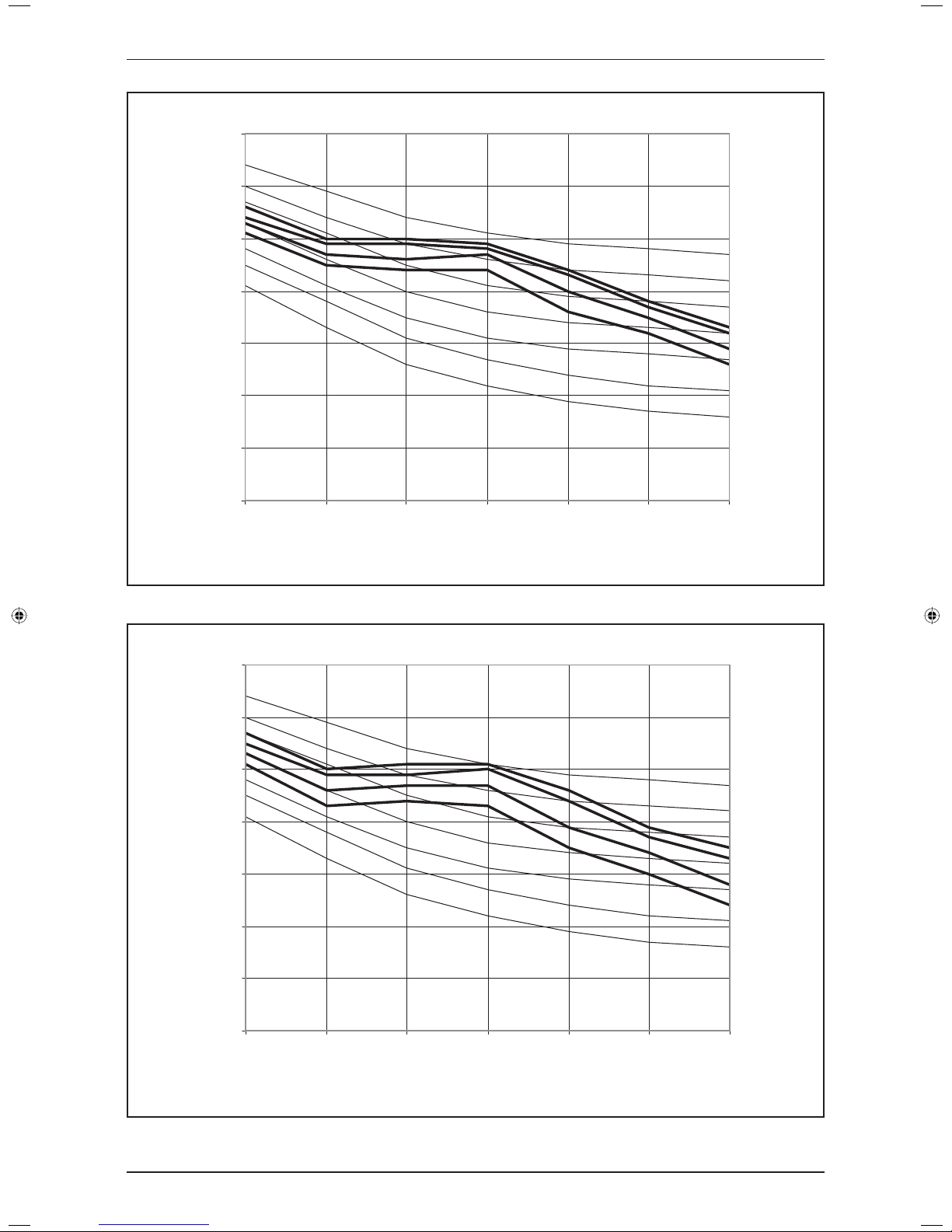
125 250 500 1000 2000 4000 8000
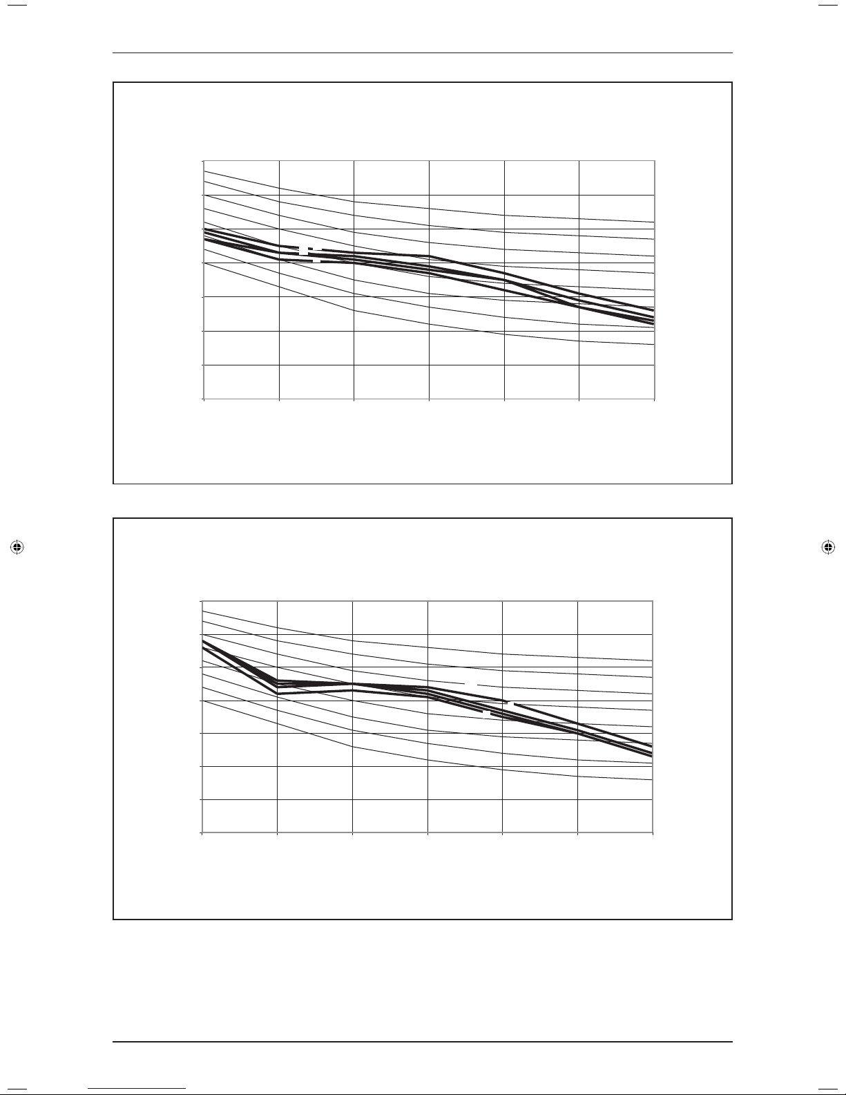
NC-40
NC-35
NC-25
NC-20
NC-45
NC-50
NC-30
Measured in anechoic room at 1.4m below the centre of the unit
Tested with 2m length duct at the air discharge outlet and air return inlet
Octave-band frequency (Hz)
Sound pressure level (dB, ref 20Pa)
FD(Y)M38CXV1
SH
H
M
L
0
10
20
30
40
50
60
70
125 250 500 1000 2000 4000 8000
NC-40
NC-20
NC-45
NC-50
NC-25
NC-30
NC-35
FD(Y)M40CXV1
Measured in anechoic room at 1.4m below the centre of the unit
Tested with 2m length duct at the air discharge outlet and air return inlet
Octave-band frequency (Hz)
Sound pressure level (dB, ref 20Pa)
SH
H
L
M
23
Sound Data
0
10
20
30
40
50
60
70
125 250 500 1000 2000 4000 8000
NC-40
NC-25
NC-20
NC-45
NC-50
SH
L
NC-30
H
M
NC-35
FD(Y)M50CXV1
Measured in anechoic room at 1.5m below the centre of the unit
Tested with 2m length duct at the air discharge outlet and air return inlet
Octave-band frequency (Hz)
Sound pressure level (dB, ref 20Pa)
0
10
20
30
40
50
60
70
125 250 500 1000 2000 4000 8000
NC-40
NC-20
NC-45
NC-50
SH
L
NC-25
NC-30
H
M
NC-35
FD(Y)M60CXV1
Measured in anechoic room at 1.5m below the centre of the unit
Tested with 2m length duct at the air discharge outlet and air return inlet
Octave-band frequency (Hz)
Sound pressure level (dB, ref 20Pa)
24
Sound Data
Octave-band frequency (Hz)
Sound pressure level (dB, ref 20Pa)
FD(Y)B10CXV1
0
10
20
30
40
50
60
70
125 250 500 1000 2000 4000 8000
NC-50
NC-45
NC-40
NC-35
NC-30
NC-25
NC-20
H
M
L
Sound pressure level (dB, ref 20Pa)
FD(Y)B15CXV1
0
10
20
30
40
50
60
70
125 250 500 1000 2000 4000 8000
Octave-band frequency (Hz)
NC-50
NC-45
NC-40
NC-35
NC-30
NC-25
NC-20
H
M
L
25
Sound Data
FD(Y)B20CXV1
0
10
20
30
40
50
60
70
125 250 500 1000 2000 4000 8000
Octave-band frequency (Hz)
Sound pressure level (dB, ref 20Pa)
NC-20
NC-30
NC-25
NC-35
NC-40
NC-45
NC-50
NC-55
H
M
L
FD(Y)B25CXV1
0
10
20
30
40
50
60
70
125 250 500 1000 2000 4000 8000
Octave-band frequency (Hz)
Sound pressure level (dB, ref 20Pa)
NC-20
NC-30
NC-25
NC-35
NC-40
NC-45
NC-50
NC-55
H
M
L
26
Sound Data
FD(Y)B30CXV1
0
10
20
30
40
50
60
70
125 250 500 1000 2000 4000 8000
Octave-band frequency (Hz)
Sound pressure level (dB, ref 20Pa)
NC-30
NC-25
NC-35
NC-40
NC-45
NC-50
NC-55
NC-20
H
SH
M
L
FD(Y)B40CXV1
0
10
20
30
40
50
60
70
125 250 500 1000 2000 4000 8000
Octave-band frequency (Hz)
Sound pressure level (dB, ref 20Pa)
NC-20
NC-30
NC-25
NC-35
NC-40
NC-45
NC-50
NC-55
H
SH
M
L
27
Sound Data
FD(Y)B50CXV1
0
10
20
30
40
50
60
70
125 250 500 1000 2000 4000 8000
Octave-band frequency (Hz)
Sound pressure level (dB, ref 20Pa)
NC-20
NC-30
NC-25
NC-35
NC-40
NC-45
NC-50
NC-55
H
SH
M
L
FD(Y)B60CXV1
0
10
20
30
40
50
60
70
125 250 500 1000 2000 4000 8000
Octave-band frequency (Hz)
Sound pressure level (dB, ref 20Pa)
NC-20
NC-30
NC-25
NC-35
NC-40
NC-45
NC-50
NC-55
H
SH
M
L
 Loading...