

Page 1

INSTALLATION AND
OPERATION MANUAL
Split System air conditioners
FDEQ71B8V3B
FDEQ100B8V3B
FDEQ125B8V3B
Page 2
13
1
3
9
1
4
3
5
1
2
3 4
1
2
1
≥300
2
W
1
5
2
1
3
5
4
2 3 4
7
1
2
3
3
1
2
3
1
2
3
1
5
2
6
2
5
6
44
752
668
5
5
A
B
C
1
2
34
4
123
4
123
4
123
8
1
3
12
P
P
2
1
5
M
P
P
2
1
6
3
12
P
P
2
1
5
SS
3
12
P
5
P
2
1
X40A
6 7 8 9
9
4
123
12
5
M
P
1P2
6 6
3
4
h
D
1
2
3
3
P
1P2
P
1P2
10
1
2
3
4
3
12
123
P1P
2
5
M
P
1P2
6
10
13
14
11 12
18~35
RR71~125
RQ71~125
REQ71~125
RQ71~125
REQ71~125
°C DB
°C WB
°C DB
°C WB
°C DB
°C WB
°C DB
°C DB
14~25
18~35
12~25
18~35
12~25
15~24
15~24
–15~46
–5~46
≤80%
10~46
–9~21
°C DB
–10~15
°C WB
°C DB
–9~21
–10~15
°C WB
11
15
4
7
6
2
1
10
2
8
4 15
1
1
3
2
P
P
1
2
8
7
109
11
6
6
Page 3
01
.
02
03
04
05
06
07
08
09
10
11
12
13
14
15
16
17
18
19
20
21
22
23
24
ATITIKTIES-DEKLARACIJA
ATBILSTĪBAS-DEKLARĀCIJA
VYHLÁSENIE-ZHODY
CE -
CE -
CE -
CE - UYUMLULUK-BİLDİRİSİ
ZJAVA O SKLADNOSTI
VASTAVUSDEKLARATSIOON
ДЕКЛАРАЦИЯ-ЗА-СЪОТВЕТСТВИЕ
CE - I
CE -
CE -
z vso odgovornostjo izjavlja, da so modeli klimatskih naprav, na katere se izjava nanaša:
25
01
02
03
04
05
06
07
08
09
10
11
12
13
14
15
16
17
18
19
20
21
22
23
24
25
01
02
03
04
05
06
07
08
09
10
11
12
13
14
15
16
17
18
19
20
21
22
23
24
25
01
02
03
04
05
06
07
08
09
10
11
12
13
14
15
16
17
18
19
20
21
22
23
24
25
.
.
.
.
*
Direktive z vsemi spremembami.
Direktiivid koos muudatustega.
Директиви, с техните изменения.
Direktyvose su papildymais.
Direktīvās un to papildinājumos.
Smernice, v platnom znení.
Değiştirilmiş halleriyle Yönetmelikler.
Direktiver, med senere ændringer.
Direktiv, med företagna ändringar.
Direktiver, med foretatte endringer.
Direktiivejä, sellaisina kuin ne ovat muutettuina.
v platném znění.
Smjernice, kako je izmijenjeno.
irányelv(ek) és módosításaik rendelkezéseit.
z późniejszymi poprawkami.
kinnitab oma täielikul vastutusel, et käesoleva deklaratsiooni alla kuuluvad kliimaseadmete mudelid:
декларира на своя отговорност, че моделите климатична инсталация, за които се отнася тази декларация:
visiška savo atsakomybe skelbia, kad oro kondicionavimo prietaisų modeliai, kuriems yra taikoma ši deklaracija:
ar pilnu atbildību apliecina, ka tālāk uzskaitīto modeĮu gaisa kondicionētāji, uz kuriem attiecas šī deklarācija:
vyhlasuje na vlastnú zodpovednosť, že tieto klimatizačné modely, na ktoré sa vzťahuje toto vyhlásenie:
tamamen kendi sorumluluğunda olmak üzere bu bildirinin ilgili olduğu klima modellerinin aşağıdaki gibi olduğunu beyan eder:
megfelelnek az alábbi szabvány(ok)nak vagy egyéb irányadó dokumentum(ok)nak, ha azokat előírás szerint használják:
spełniają wymogi następujących norm i innych dokumentów normalizacyjnych, pod warunkiem że używane są zgodnie z naszymi
instrukcjami:
sunt în conformitate cu următorul (următoarele) standard(e) sau alt(e) document(e) normativ(e), cu condiţia ca acestea să fie utilizate în
conformitate cu instrucţiunile noastre
skladni z naslednjimi standardi in drugimi normativi, pod pogojem, da se uporabljajo v skladu z našimi navodili:
on vastavuses järgmis(t)e standardi(te)ga või teiste normatiivsete dokumentidega, kui neid kasutatakse vastavalt meie juhenditele:
съответстват на следните стандарти или други нормативни документи, при условие, че се използват съгласно нашите
инструкции:
atitinka žemiau nurodytus standartus ir (arba) kitus norminius dokumentus su sąlyga, kad yra naudojami pagal mūsų nurodymus:
tad, ja lietoti atbilstoši ražotāja norādījumiem, atbilst sekojošiem standartiem un citiem normatīviem dokumentiem:
sú v zhode s nasledovnou(ými) normou(ami) alebo iným(i) normatívnym(i) dokumentom(ami), za predpokladu, že sa používajú v súlade
s našim návodom:
ürünün, talimatlarımıza göre kullanılması koşuluyla aşağıdaki standartlar ve norm belirten belgelerle uyumludur:
.
. 07
*
*
.
.
.
съгласно
KEMA
2024351-QUA/EMC02-
järgi vastavalt
certifikatom
KEMA
pagal
v skladu s
KEMA
KEMA
и оценено положително от
ja heaks kiidetud
ir patvirtinta
DAIKIN.TCF.021
in odobreno s strani
DAIKIN.TCF.021
DAIKIN.TCF.021
DAIKIN.TCF.021
Directivelor, cu amendamentele respective.
2024351-QUA/EMC02-4565
2024351-QUA/EMC02-4565
2024351-QUA/EMC02-4565
kot je določeno v tehnični mapi
nagu on näidatud tehnilises dokumentatsioonis
sertifikaadile
както е заложено в Акта за техническа конструкция
Сертификат
kaip nurodyta Techninėje konstrukcijos byloje
21 Забележка *
pažymėjimą
22 Pastaba *
4565
19 Opomba *
20 Märkus
.
.
.
.
i
.
.
.
*
.
.
tarafından
KEMA
göre
podľa
sertifikasına
KEMA
pozitīvajam lēmumam ko apliecina
a kladne posúdené
KEMA
2024351-QUA/EMC02-4565
, atbilstoši
DAIKIN.TCF.021
DAIKIN.TCF.021
Teknik Yapı Dosyasında belirtildiği gibi ve
2024351-QUA/EMC02-4565
2024351-QUA/EMC02-4565
kā noteikts tehniskajā dokumentācijā
olumlu olarak değerlendirilmiştir.
sertifikāts
ako je to stanovené v Súbore technickej konštrukcie
Certifikátu
DAIKIN.TCF.021
Not
23 Piezīmes *
24 Poznámka *
25
.
.
Zandvoordestraat 300, B-8400 Oostende, Belgium
.
*
IZJAVA-O-USKLAĐENOSTI
DEKLARACJA-ZGODNOŚCI
DECLARAŢIE-DE-CONFORMITATE
CE - MEGFELELŐSÉGI-NYILATKOZAT
CE -
CE -
CE -
PROHLÁŠENÍ-O-SHODĚ
CE - ERKLÆRING OM-SAMSVAR
CE - ILMOITUS-YHDENMUKAISUUDESTA
CE -
prohlašuje ve své plné odpovědnosti, že modely klimatizace, k nimž se toto prohlášení vztahuje:
izjavljuje pod isključivo vlastitom odgovornošću da su modeli klima uređaja na koje se ova izjava odnosi:
teljes felelőssége tudatában kijelenti, hogy a klímaberendezés modellek, melyekre e nyilatkozat vonatkozik:
deklaruje na własną i wyłączną odpowiedzialność, że modele klimatyzatorów, których dotyczy niniejsza deklaracja:
declară pe proprie răspundere că aparatele de aer condiţionat la care se referă această declaraţie:
erklærer under eneansvar, at klimaanlægmodellerne, som denne deklaration vedrører:
deklarerar i egenskap av huvudansvarig, att luftkonditioneringsmodellerna som berörs av denna deklaration innebär att:
erklærer et fullstendig ansvar for at de luftkondisjoneringsmodeller som berøres av denne deklarasjon innebærer at:
ilmoittaa yksinomaan omalla vastuullaan, että tämän ilmoituksen tarkoittamat ilmastointilaitteiden mallit:
CE - DECLARAÇÃO-DE-CONFORMIDADE СЕ - ЗАЯВЛЕНИЕ-О-СООТВЕТСТВИИ
CE - OPFYLDELSESERKLÆRING
CE - FÖRSÄKRAN-OM-ÖVERENSTÄMMELSE
CE - ¢H§ø™H ™YMMOPºø™H™
CE - DECLARACION-DE-CONFORMIDAD
CE - DICHIARAZIONE-DI-CONFORMITA
estão em conformidade com a(s) seguinte(s) norma(s) ou outro(s) documento(s) normativo(s), desde que estes sejam utilizados de
acordo com as nossas instruções:
соответствуют следующим стандартам или другим нормативным документам, при условии их использования согласно нашим
инструкциям:
overholder følgende standard(er) eller andet/andre retningsgivende dokument(er), forudsat at disse anvendes i henhold til vore
instrukser:
respektive utrustning är utförd i överensstämmelse med och följer följande standard(er) eller andra normgivande dokument, under
förutsättning att användning sker i överensstämmelse med våra instruktioner:
respektive utstyr er i overensstemmelse med følgende standard(er) eller andre normgivende dokument(er), under forutssetning av at
disse brukes i henhold til våre instrukser:
vastaavat seuraavien standardien ja muiden ohjeellisten dokumenttien vaatimuksia edellyttäen, että niitä käytetään ohjeidemme
mukaisesti:
za předpokladu, že jsou využívány v souladu s našimi pokyny, odpovídají následujícím normám nebo normativním dokumentům:
u skladu sa slijedećim standardom(ima) ili drugim normativnim dokumentom(ima), uz uvjet da se oni koriste u skladu s našim uputama:
Directives, as amended.
Direktiven, gemäß Änderung.
Directives, telles que modifiées.
Richtlijnen, zoals geamendeerd.
Directivas, según lo enmendado.
Direttive, come da modifica.
√‰ËÁÈÒv, fiˆ˜ ¤¯Ô˘Ó ÙÚÔÔÔÈËı›.
Directivas, conforme alteração em.
Директив со всеми поправками.
Low Voltage 73/23/EEC
Machinery Safety 98/37/EEC
Electromagnetic Compatibility 89/336/EEC *
ob upoštevanju določb:
vastavalt nõuetele:
следвайки клаузите на:
laikantis nuostatų, pateikiamų:
ievērojot prasības, kas noteiktas:
održiavajúc ustanovenia:
bunun koşullarına uygun olarak:
under iagttagelse af bestemmelserne i:
enligt villkoren i:
gitt i henhold til bestemmelsene i:
noudattaen määräyksiä:
za dodržení ustanovení předpisu:
prema odredbama:
követi a(z):
zgodnie z postanowieniami Dyrektyw:
în urma prevederilor:
vilket också
ifølge
KEMA
KEMA
i henhold
som positivt intygas av
KEMA
on hyväksynyt
og gjennom positiv bedømmelse av
DAIKIN.TCF.021
KEMA
og positivt vurderet af
DAIKIN.TCF.021
DAIKIN.TCF.021
ja jotka
mukaisesti.
DAIKIN.TCF.021
2024351-QUA/EMC02-4565
2024351-QUA/EMC02-4565
Certifikat
Certifikat 2024351-QUA/EMC02-4565
som anført i den Tekniske Konstruktionsfil
utrustningen är utförd i enlighet med den Tekniska Konstruktionsfilen
som det fremkommer i den Tekniske Konstruksjonsfilen
Sertifikat 2024351-QUA/EMC02-4565
jotka on esitetty Teknisessä Asiakirjassa
Sertifikaatin
framgår av
til
10 Bemærk *
11 Information *
12 Merk *
13 Huom *
conformément
overeenkomstig
KEMA
according to
KEMA
KEMA
positiv ausgezeichnet gemäß
KEMA
et jugé positivement par
en in orde bevonden door
and judged positively by
aufgeführt und von
DAIKIN.TCF.021
DAIKIN.TCF.021
DAIKIN.TCF.021
DAIKIN.TCF.021
prema
KEMA
v souladu
KEMA
în conformitate
KEMA
KEMA
igazolta a megfelelést
KEMA
şi apreciate pozitiv de
, pozytywną opinią
i pozitivno ocijenjeno od strane
a pozitivně zjištěno
DAIKIN.TCF.021
DAIKIN.TCF.021
DAIKIN.TCF.021
DAIKIN.TCF.021
szerint.
tanúsítvány
műszaki konstrukciós dokumentáció alapján, a(z)
2024351-QUA/EMC02-4565
2024351-QUA/EMC02-4565
2024351-QUA/EMC02-4565
DAIKIN.TCF.021
osvědčením
s
jak bylo uvedeno v souboru technické konstrukce
kako je izloženo u Datoteci o tehničkoj konstrukciji
Certifikatu
a(z)
2024351-QUA/EMC02-4565
2024351-QUA/EMC02-4565
Certificatul
Świadectwem
a(z)
cu
zgodnie z archiwalną dokumentacją konstrukcyjną
conform celor stabilite în Dosarul tehnic de construcţie
Notă *
14 Poznámka *
15 Napomena *
16 Megjegyzés *
17 Uwaga *
18
Jiro Tomita
Director Quality Assurance
Ostend, 2nd of November 2005
KEMA
según
Û‡Ìʈӷ Ì ÙÔ
KEMA
de acordo com o
KEMA
KEMA
secondo
KEMA
y juzgado positivamente por
Î·È ÎÚ›ÓÂÙ·È ıÂÙÈο ·fi ÙÔ
e com o parecer positivo de
и в соответствии с положительным решением
DAIKIN.TCF.021
DAIKIN.TCF.021
DAIKIN.TCF.021
e giudicato positivamente da
DAIKIN.TCF.021
DAIKIN.TCF.021
2024351-QUA/EMC02-4565
declares under its sole responsibility that the air conditioning models to which this declar ation relates:
erklärt auf seine alleinige Verantwortung daß die Modelle der Klimageräte für die diese Erklärung bestimmt ist:
déclare sous sa seule responsabilité que les appareils d'air conditionné visés par la présente déclar ation:
verklaart hierbij op eigen exclusieve verantwoordelijkheid dat de airconditioning units waarop deze verklaring betrekking heeft:
declara baja su única responsabilidad que los modelos de aire acondicionado a los cuales hace referencia la declaración:
CE - DECLARATION-OF-CONFORMITY
CE - KONFORMITÄTSERKLÄRUNG
CE - DECLARATION-DE-CONFORMITE
CE - CONFORMITEITSVERKLARING
Daikin Europe N.V.
dichiara sotto sua responsabilità che i condizionatori modello a cui è r iferita questa dichiarazione:
2024351-QUA/EMC02-4565
2024351-QUA/EMC02-4565
2024351-QUA/EMC02-4565
Certificate
Certificat
wie in der Technischen Konstruktionsakte
Zertifikat
the
02 Hinweis *
au
tel que stipulé dans le Fichier de Construction Technique
zoals vermeld in het Technisch Constructiedossier
03 Remarque *
04 Bemerk *
Certificaat 2024351-QUA/EMC02-4565
tal como se expone en el Archivo de Construcción Técnica
05 Nota
as set out in the Technical Construction File
‰ЛПТУВИ МВ ·ФОПВИЫЩИО‹ ЩЛ˜ В˘ı‡УЛ fiЩИ Щ· МФУЩ¤П· ЩˆУ ОПИМ·ЩИЫЩИОТУ Ы˘ЫОВ˘ТУ ЫЩ· ФФ›· ·У·К¤ЪВЩ·И Л ·ЪФ‡Ы· ‰‹ПˆЫЛ:
заявляет, исключительно под свою ответственность, что модели кондиционеров воздуха, к которым относится настоящее заявление:
are in conformity with the following standard(s) or other normative document(s), provided that these are used in accordance with our
instructions:
der/den folgenden Norm(en) oder einem anderen Normdokument oder -dokumenten entspricht/entsprechen, unter der Voraussetzung,
daß sie gemäß unseren Anweisungen eingesetzt werden:
declara sob sua exclusiva responsabilidade que os modelos de ar condicionado a que esta declaração se refere:
FDEQ71B8V3B, FDEQ100B8V3B, FDEQ125B8V3B
sont conformes à la/aux norme(s) ou autre(s) document(s) nor matif(s), pour autant qu'ils soient utilisés conformément à nos instructions:
conform de volgende norm(en) of één of meer andere bindende documenten zijn, op voorwaarde dat ze worden gebruikt overeenkomstig
onze instructies:
están en conformidad con la(s) siguiente(s) norma(s) u otro(s) documento(s) nor mativo(s), siempre que sean utilizados de acuerdo con
nuestras instrucciones:
sono conformi al(i) seguente(i) standard(s) o altro(i) documento(i) a carattere normativo, a patto che vengano usati in conformità alle
nostre istruzioni:
В›У·И Ы‡МКˆУ· МВ ЩФ(·) ·ОfiПФ˘ıФ(·) ЪfiЩ˘Ф(·) ‹ ¿ППФ ¤ББЪ·КФ(·) О·УФУИЫМТУ, ˘fi ЩЛУ ЪФ¸fiıВЫЛ fiЩИ ¯ЪЛЫИМФФИФ‡УЩ·И
Û‡Ìʈӷ Ì ÙȘ Ô‰ËÁ›Â˜ Ì·˜:
following the provisions of:
gemäß den Vorschriften der:
conformément aux stipulations des:
overeenkomstig de bepalingen van:
siguiendo las disposiciones de:
EN60335-2-40,
secondo le prescrizioni per:
Ì ًÚËÛË Ùˆv ‰È·Ù¿Íˆv Ùˆv:
de acordo com o previsto em:
в соответствии с положениями:
01 Note *
2024351-QUA/EMC02-4565
2024351-QUA/EMC02-4565
Certificado 2024351-QUA/EMC02-4565
Certificato
el
il
delineato nel File Tecnico di Costruzione
fiˆ˜ ÚÔÛ‰ÈÔÚ›˙ÂÙ·È ÛÙÔ ∞Ú¯Â›Ô ∆¯ÓÈ΋˜ ∫·Ù·Û΢‹˜
¶ИЫЩФФИЛЩИОfi
™ËÌ›ˆÛË
06 Nota *
2024351-QUA/EMC02-4565
Свидетельству
tal como estabelecido no Ficheiro Técnico de Construção
Certificado
как указано в Досье технического толкования
согласно
08 Nota
09 Примечание *
3PW25005-2
Page 4
FDEQ71B8V3B
FDEQ100B8V3B
FDEQ125B8V3B
Split System air conditioners
CONTENTS Page
Installing the unit ...................................................... 1
Before installation.............................................................................. 1
Selecting installation site................................................................... 2
Preparations before installation......................................................... 2
Indoor unit installation .......................................................................3
Refrigerant piping work .....................................................................3
Drain piping work .............................................................................. 3
Electric wiring work ........................................................................... 4
Wiring example and how to set the remote controller ....................... 4
Wiring example ................................................................................. 5
Field setting....................................................................................... 5
Test operation.................................................................................... 6
Operating the unit ..................................................... 6
Names and functions of parts ........................................................... 6
Important information regarding the refrigerant used........................ 6
Operation range ................................................................................6
Operation procedure .........................................................................7
Optimum operation............................................................................ 7
Not a malfunction of the air conditioner............................................. 7
Troubleshooting................................................................................. 8
Maintenance...................................................................................... 8
THANK YOU FOR PURCHASING THIS DAIKIN AIR
CONDITIONER. CAREFULLY READ THE CHAPTER
"OPERATING THE UNIT" ON PAGE 6 BEFORE USING
THE AIR CONDITIONER. IT WILL TELL YOU HOW TO
USE THE UNIT PROPERLY AND HELP YOU IF ANY
TROUBLE OCCURS. AFTER READING THE MANUAL,
FILE IT AWAY FOR FUTURE REFERENCE.
Installation and
operation manual
INSTALLING THE UNIT
READ THESE INSTRUCTIONS CAREFULLY BEFORE
INSTALLATION.
IMPROPER INSTALLATION OR ATTACHMENT OF
EQUIPMENT OR ACCESSORIES COULD RESULT IN
ELECTRIC SHOCK, SHORT-CIRCUIT, LEAKS, FIRE OR
OTHER DAMAGE TO THE EQUIPMENT. BE SURE ONLY
TO USE ACCESSORIES MADE BY DAIKIN WHICH ARE
SPECIFICALLY DESIGNED FOR USE WITH THE
EQUIPMENT AND HAVE THEM INSTALLED BY A
PROFESSIONAL.
IF UNCERTAINTY ARISES ABOUT THE INSTALLATION
PROCEDURES OR USE, ALWAYS CONTACT YOUR
DAIKIN DEALER FOR ADVICE AND INFORMATION.
BEFORE INSTALLATION
■ Leave the unit inside its packaging until you reach the
installation site. Where unpacking is unavoidable, use a sling of
soft material or protective plates together with a rope when
lifting, this to avoid damage or scratches to the unit.
■ Refer to the installation manual of the outdoor unit for items not
described in this manual.
■ Do not place objects in direct proximity of the outdoor unit and
do not let leaves and other debris accumulate around the unit.
Leaves are a hotbed for small animals which can enter the unit.
Once in the unit, such animals can cause malfunctions, smoke
or fire when making contact with electrical parts.
Precautions
■ Do not install or operate the unit in rooms mentioned below.
• Places with mineral oil, or filled with oil vapour or spray like in
kitchens. (Plastic parts may deteriorate.)
• Where corrosive gas like sulphurous gas exists. (Copper
tubing and brazed spots may corrode.)
• Where volatile flammable gas like thinner or gasoline is used.
• Where machines generating electromagnetic waves can be
found. (Control system may malfunction.)
• Where the air contains high levels of salt such as air near the
ocean and where voltage fluctuates a lot (e.g. in factories).
Also in vehicles or vessels.
■ Do not install accessories on the casing directly. Drilling holes in
the casing may damage electrical wires and consequently cause
fire.
Installation and operation manual
1
Optional accessories
Refer to catalogues and technical literature for selecting the remote
controller, and install it in an appropriate place.
FDEQ71~125B8V3B
Split System air conditioners
4PW23693-1A
Page 5
For the following items, take special care during
construction and check after installation is finished
Tick ✓
when
checked
Is the indoor unit fixed firmly?
■
■
■
■
■
■
■
■
■
■
The unit may drop, vibrate or make noise.
Is the gas leak test finished?
It may result in insufficient cooling.
Is the unit fully insulated?
Condensate water may drip.
Does drainage flow smoothly?
Condensate water may drip.
Does the power supply voltage correspond to that shown on the
name plate?
The unit may malfunction or components may burn out.
Are wiring and piping correct?
The unit may malfunction or components may burn out.
Is the unit safely grounded?
Dangerous at electric leakage.
Is the wiring size according to specifications?
The unit may malfunction or components may burn out.
Is nothing blocking the air outlet or inlet of either the indoor or
outdoor units?
It may result in insufficient cooling.
Are refrigerant piping length and additional refrigerant charge
noted down?
The refrigerant charge in the system might not be clear.
This to avoid confusion for future maintenance and serving of
the installation.
Notes to the installer
■ Be sure to instruct the customer how to properly operate the
system and show him/her the enclosed operation manual.
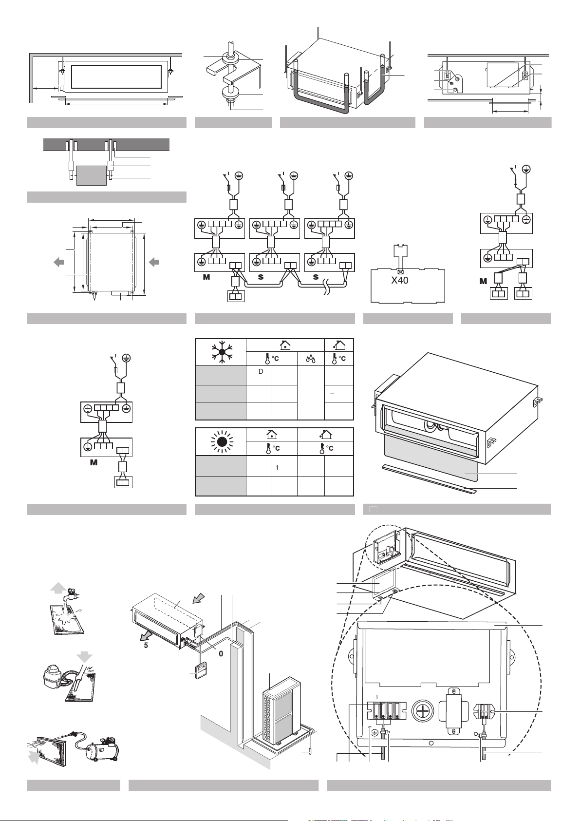
SELECTING INSTALLATION SITE (See figure 1 and 4)
1. Select an installation site where the following conditions are
fulfilled and that meets your customer's approval.
• Where optimum air distribution can be ensured.
• Where nothing blocks air passage.
• Where condensate water can be properly drained.
• Where the false ceiling is not noticeably on an incline.
• Where sufficient clearance for maintenance and service can
be ensured.
• Where piping between indoor and outdoor units is possible
within the allowable limit. (Refer to the installation manual of
the outdoor unit.)
•Keep indoor unit, outdoor unit, power supply wiring and
transmission wiring at least 1 meter away from televisions
and radios. This is to prevent image interference and noise
interference in those electrical appliances.
(Electric noise may be generated depending on the conditions
under which the electric wave is generated, even if 1 meter is
kept.)
•Never place anything under the indoor unit that you don't want to
get wet. The unit may sweat when the humidity is over 80% or
when the drain outlet is clogged.
•Never place other heating equipment directly beneath the indoor
unit. Subject to deformation caused by heat.
• The unit should be installed at least 2.5 m from the floor.
2. Use suspension bolts for installation. Check whether the ceiling
is strong enough to support the weight of the indoor unit. If
there is a risk, reinforce the ceiling before installing the unit.
1 Service space ≥300
2 Drain pipe
3 Power supply wiring port
4 Tr ansmission wiring port
5 Gas pipe
6 Liquid pipe
PREPARATIONS BEFORE INSTALLATION
1. Suspension bolt position. (See figure 6)
Model A B C
FDEQ71+100 920 960 990
FDEQ125 1320 1360 1390
1 Indoor unit
2 Pipe
3 Switch box
4 Suspension bolt (x4)
5 Suspension bolt pitch distance
For other installation than standard installation, contact your
Daikin dealer for details.
3. The fan speed for this indoor unit is preset to provide high
external static pressure.
If lower external static pressure is required, reset the external
static pressure by changing the initial setting from the remote
controller.
Refer to "Setting of static pressure" on page 5.
4. Install the suspension bolts.
(Use M10 size bolt for the suspension bolt.) Use anchors for
existing ceilings, and a sunken insert, sunken anchors or other
field supplied parts for new ceilings to reinforce the ceiling in
order to bear the weight of the unit.
Installation example (See figure 5)
1 Anchor
2 Ceiling slab
3 Long nut or turn-buckle
4 Suspension bolt
5 Indoor unit
NOTE
All the above parts are field supplied.
FDEQ71~125B8V3B
Split System air conditioners
4PW23693-1A
Installation and operation manual
2
Page 6

INDOOR UNIT INSTALLATION
When installing optional accessories read also the installation
manual of the optional accessories. Depending on the field
conditions, it may be easier to install optional accessories before the
indoor unit is installed.
1. Install the indoor unit temporarily.
• Attach the hanger bracket to the suspension bolt. Be sure to
fix it securely by using a nut and washer from the upper and
lower sides of the hanger bracket. (See figure 2)
1 Nut (field supply)
2 Washer for hanger bracket (field supply)
3 Tighten (double nut)
2. Check if the unit is horizontally levelled.
• If the unit is tilted against condensate flow, condensate water
could drip out of the unit.
• Check if the unit is levelled at all four corners with a water
level or a water-filled vinyl tube as shown in figure 3.
1 Water level
2 Vinyl tube
3. Tighten the upper nut.
NOTE
Required service opening dimensions for air filter
maintenance (See figure 1 and figure 4)
W Width of service opening
D Depth of service opening
h Distance unit-false ceiling
Model W D
FDEQ71+100 ≥920 If h≤30 ⇒ D≥100
FDEQ125 ≥1320 If h>30 ⇒ D≥200
REFRIGERANT PIPING WORK
For refrigerant piping of outdoor unit, refer to the installation manual
supplied with the outdoor unit.
NOTE
■ Use a pipe cutter and flare suitable for the used refrigerant.
■ Apply ether oil or ester oil around the flare portions before
■ To prevent dust, moisture or other foreign matter from infiltrating
■ The outdoor unit is charged with refrigerant.
■ Be sure to use both a spanner and torque wrench together when
■ Refer to Ta ble 1 for the dimensions of flare nut spaces and the
All field piping must be provided by a licensed
refrigeration technician and must comply with the
relevant local and national codes.
connecting.
the tube, either pinch the end, or cover it with tape.
connecting or disconnecting pipes to/from the unit.
1 Torque wrench
2 Spanner
3 Piping union
4 Flare nut
1
2
4
3
appropriate tightening torque. (Overtightening may damage the
flare and cause leaks.)
Ta ble 1
Flare
Pipe
gauge
Ø9.5
Ø15.9
Tightening torque
32.7~39.9 N•m
(333~407 kgf•cm)
61.8~75.4 N•m
(630~770 kgf•cm)
dimension A
(mm)
12.0~12.4
18.6~19.0
Flare shape
±2
90°
45°
±2
A
R=0.4~0.8
■ When connecting the flare nut, coat the flare both inside and
outside with ether oil or ester oil and initially tighten by hand
before tightening firmly.
Coat here with ether oil or ester oil
■ Check the pipe connector for gas leaks, then insulate it.
1 Liquid pipe
2 Gas pipe
3 Insulation for fitting of liquid line (field
supply). The insulation should
withstand 80°C.
4 Insulation for fitting of gas line (field
supply). The insulation should
withstand 120°C.
5 Clamps (use 2 clamps per insulation)
3
5
4
12
DRAIN PIPING WORK
1 Install the drain pipes.
-Keep piping as short as possible and slope it downwards so
that air may not remain trapped inside the pipe.
-Keep pipe size equal to or greater than that of the connecting
pipe.
-For connection to the drain socket: use a flexible hose (field
supply) and clamp it firmly. This to avoid leaks due to
operating vibration of the unit.
- After clamping, isolate the drain socket. This is to avoid leaks
due to sweating of the unit.
1 Metal clamp
2 Flexible hose
3 Insulation
4 Plastic clamp
- Do not use a trap in the drain piping.
-Never put the end of the drain hose into water.
2 Insulate the drain hose inside the building.
3 Drain check
-Execute the drain check before installing the duct
- Make sure that the drain hose is firmly connected
-Pour some water into the drain pan to check if the water flows
smoothly.
4 2
1
3
Installation and operation manual
3
FDEQ71~125B8V3B
Split System air conditioners
4PW23693-1A
Page 7

ELECTRIC WIRING WORK
General instructions
■ All field supplied parts and materials and electric works must
conform to local codes.
■ Use copper wire only.
■ Follow the "Wiring diagram" attached to the switch box cover to
wire the outdoor unit, indoor units and the remote controller. For
details on hooking up the remote controller, refer to the
"Installation manual of the remote controller".
■ All wiring must be performed by an authorized electrician.
■ A circuit breaker capable of shutting down power supply to the
entire system must be installed.
............Field wiring
.....................Terminal
..........................Connector
...................Wire clamp
..........................Protective earth (screw)
BLK ........................ Black
BLU........................Blue
BRN .......................Brown
GRY ....................... Grey
ORG....................... Orange
RED .......................Red
WHT....................... White
Wiring parts table
A1P........................ Printed circuit board
C1R ....................... Capacitor (fan)
F1T ........................ Thermal fuse (136°C) (embedded in T1R)
HAP ....................... Light emitting diode (service monitor - green)
M1F ....................... Motor (fan)
R1T........................ Thermistor (air)
R2T........................ Thermistor (coil)
RC ......................... Signal receiver circuit
RyF1~4.................. Magnetic relay (fan)
RyP........................ Magnetic relay (drain pump)
SS1........................ Selector switch (emergency)
T1R........................ Power supply transformer (220-240 V/21.8 V)
TC.......................... Signal transmission circuit
X1M,X2M............... Terminal strip
Wired remote controller
BS1........................ ON/OFF button
BS2........................ Timer mode start/stop button
BS3,BS8................ Programming time button
BS4,BS9................ Temperature setting button
BS6........................ Operation mode selector button
BS7........................ Timer ON/OFF button
BS11...................... Fan speed control button
BS12...................... Inspection/test operation button
BS14...................... Filter sign reset button
H1P........................ Light emitting diode (service monitor - red)
LCD ....................... Liquid cristal display
SS1........................ Selector switch (main/sub)
Adaptor for wiring
RyC,RyF................ Magnetic relay
NOTE
1. When using the central remote controller, see manual
for connection to the unit.
2. The remote controller model varies according to the
combination system. See technical data and
catalogues before connecting.
Specifications for field wire
Connection Wire Size
Between indoor units H05VV-U4G Local codes
Unit-Remote controller Sheathed wire (2)
NOTE
For details, refer to the chapter "Wiring example" on
0.75-1.25 mm
2
page 5.
Use H07RN-F as wiring between indoor units in case of no
protection.
Allowable length of transmission wiring between the indoor unit and
the remote controller is max. 500 m.
WIRING EXAMPLE AND HOW TO SET THE
REMOTE CONTROLLER
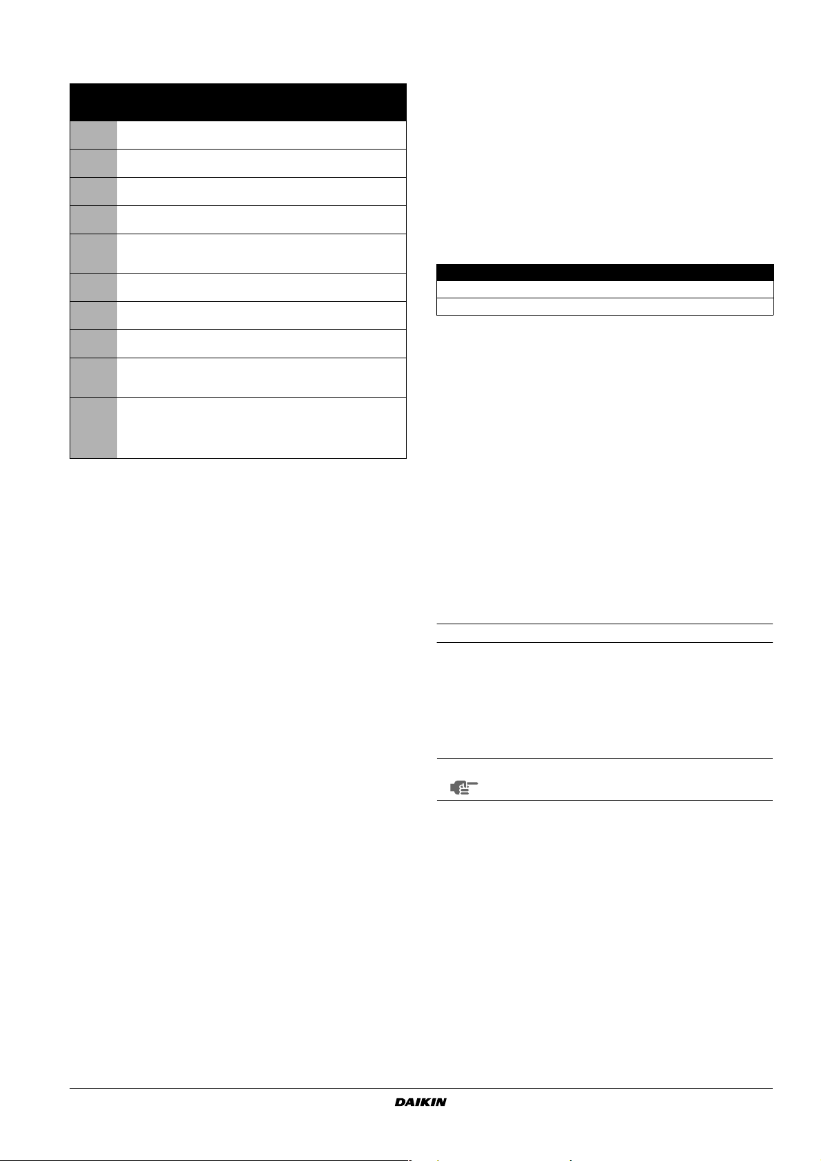
How to connect wiring
Remove the switch box cover as shown in figure 15, and make the
connections.
1 Switch box
2 Switch box cover
3 Power supply wiring port
4 Tr ansmission wiring port
5 Wiring diagram
6 Wiring clamp
7 Remote controller wiring
8 Te r minal for remote controller wiring
9 Power supply wiring
10 Te rminal for power supply wiring
11 Earth screw
Connector for optional parts
X33A...................... Connector (adaptor for wiring)
X35A...................... Connector (group control adaptor)
X40A...................... Connector (remote ON/OFF, forced off)
X60A,X61A............ Connector (interface adaptor)
FDEQ71~125B8V3B
Split System air conditioners
4PW23693-1A
Installation and operation manual
4
Page 8

Precautions
1. Observe the notes mentioned below when wiring to the power supply
terminal board.
• Do not connect wires of different gauge to the same power
supply terminal. (Looseness in the connection may cause
overheating.)
• When connecting wires of the same gauge, connect them
according to the figure.
2. Do not connect wires of different gauge to the same grounding
terminal. Looseness in the connection may deteriorate the
protection.
3. Remote controller cords and wires connecting the units should be
located at least 50 mm away from power supply wiring. Not following
this guideline may result in malfunction due to electrical noise.
4. For the remote controller wiring, refer to the "Installation manual of
the remote controller" supplied with the remote controller.
NOTE
The customer has the ability to select the remote
controller thermistor.
5. Never connect the power supply wiring to the terminal board for
transmission wiring. This mistake could damage the entire system.
6. Use only specified wires and tightly connect wires to the terminals.
Be careful that wires do not place external stress on the terminals.
Keep wiring in neat order so that they do not obstruct other
equipment such as popping open the switch box cover. Make sure
the cover closes tight. Incomplete connections could result in
overheating, and in the worst case, electric shock or fire.
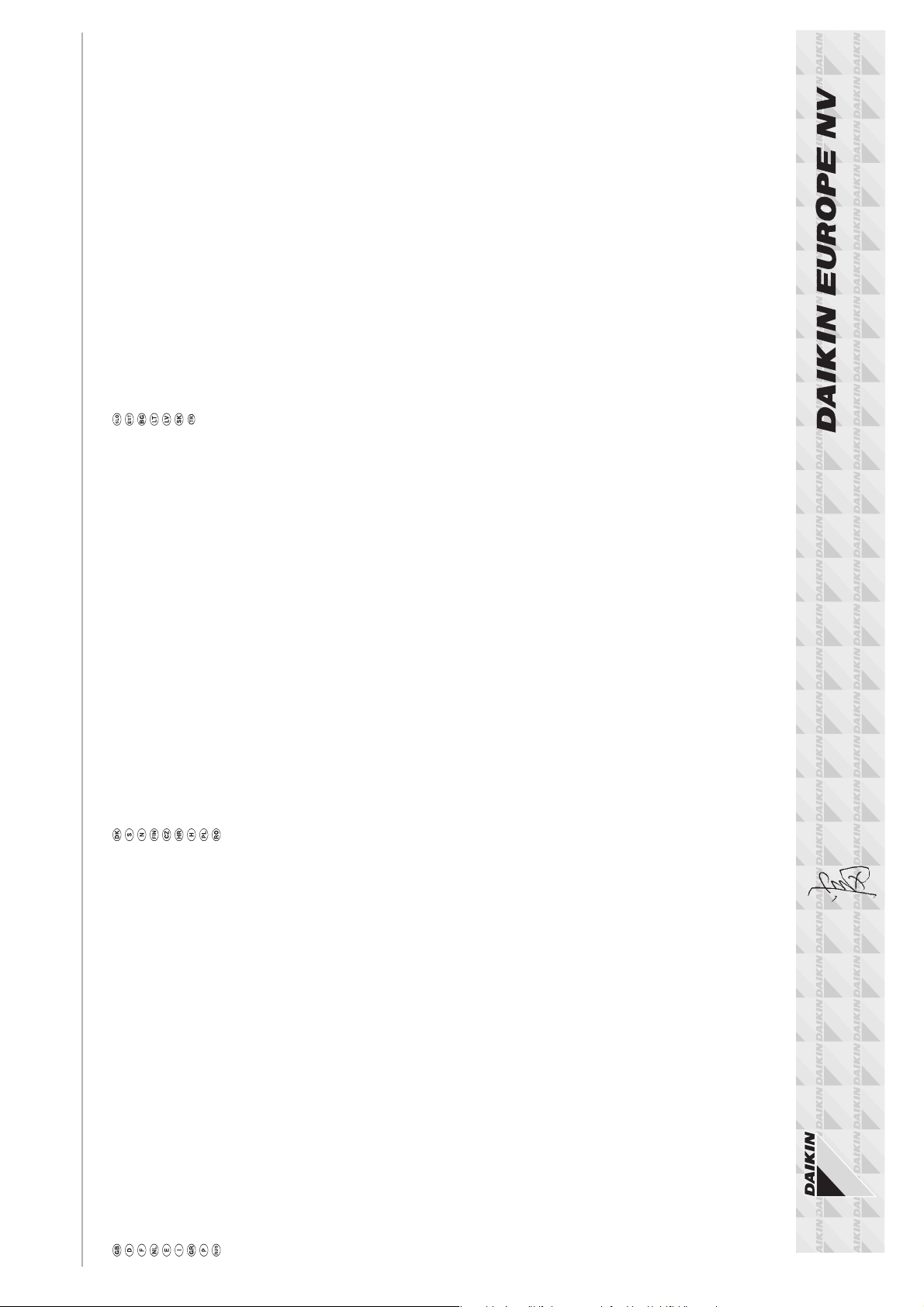
WIRING EXAMPLE
■ Fit the power supply wiring of each system with a switch and
fuse as shown in figure 7, 9 and 10.
1 Power supply
2 Main switch
3 Fuse
4 Outdoor unit
5 Indoor unit (M=master, S=slave)
6 Remote controller (optional accessory)
Precautions
1. A single switch can be used to supply power to units on the same
system. However, branch switches and branch circuit breakers must
be selected carefully.
2. Do not ground the equipment on gas pipes, water pipes, lightning
rods or crossground with telephones. Improper grounding could
result in electric shock.
FIELD SETTING
Field setting must be made from the remote controller in accordance
with the installation condition. Refer to the manual of the remote
controller.
Setting of static pressure
■ Change the SECOND CODE No. according to Ta ble 2
depending on the resistance of the connection duct.
Ta ble 2
External static
pressure
Low: 50 Pa
High: 100 Pa 02
Mode No. FIRST CODE No.
13 (23) 6
The unit is factory set for high static pressure (SECOND CODE No.
02) at the time of shipping.
Setting air filter sign
■ Remote controllers are equipped with liquid crystal display air
filter signs to display the time to clean air filters.
■ Change the SECOND CODE No. According to Ta ble 3
depending on the amount of dirt or dust in the room. (SECOND
CODE No. Is factory set to "01" for filter contamination-light.)
Ta ble 3
Spacing time of
display air filter
sign (long life
Setting
Air filter
contamination -
light
Air filter
contamination -
heavy
type)
±2500 hrs
±1250 hrs 02
Mode No.
10 (20) 0
CODE No.
FIRST
SECOND
CODE No.
01
SECOND
CODE No.
01
Complete system example (3 systems)
When using 1 remote controller for 1 indoor unit. (Normal
operation) (See figure 10)
For group control (See figure 7)
For group control, cut the jumper indicated as “master/slave” on the
PCB of the “slave” indoor units (=slave PCB). Do not cut the jumper
on the PCB of the indoor unit to which the remote controller is
connected (=master PCB).
Master Slave
Use with 2 remote controllers (See figure 9)
NOTE
It is not necessary to designate an indoor unit address
when using group control. The address is automatically set when the power is activated.
Installation and operation manual
5
Control by 2 Remote Controllers (Controlling 1 indoor unit by 2 remote controllers)
Refer to the manual of the remote controller.
FDEQ71~125B8V3B
Split System air conditioners
4PW23693-1A
Page 9

Computerised control (forced off and on/off operation)
1 Wire specifications and how to perform wiring
- Connect the input wire (option) to connector X40A on the
indoor PCB.
Wire specifications (to extend the optional wire):
Wire specification Sheathed vinyl cord or cable (2 wire)
Gauge
Length Max. 100 m
External terminal Contact that can ensure the minimum
0.75-1.25 mm
applicable load of 15 V DC, 10 mA
2
(See figure 8)
1 Input A (Input “ON”=closed contact)
2 Actuation
- The following table explains "forced off" and "on/off
operations" in response to input A.
Forced off on/off operation
Input "on" stops operation +
disables control
Input "off" enables control input on ➜ off: stops operation remote,
input off ➜ on: starts operation remote,
control is still enabled
control is still enabled
3 How to select forced off and on/off operation
Change the second code No. according to Ta ble 4. (Second
code No. is factory set to “01” for forced off.)
Ta ble 4
Setting Mode No. FIRST CODE No. SECOND CODE No.
Forced off
ON/OFF
operation
12 (22) 1
01
02
TEST OPERATION
Refer to the section of "For the following items, take special care
during construction and check after installation is finished" on page 2.
■ After finishing the construction of refrigerant piping, drain piping,
and electric wiring, conduct test operation accordingly to protect
the unit.
1 Open the gas side stop valve.
2 Open the liquid side stop valve.
3 Electrify crank case heater for 6 hours. (Not necessary for the
straight cooling type.)
4 Set to cooling operation with the remote controller and start
operation by pushing ON/OFF button.
5 Press Inspection/Test Operation button 4 times and operate at
Test Operation mode for 3 minutes.
OPERATING THE UNIT
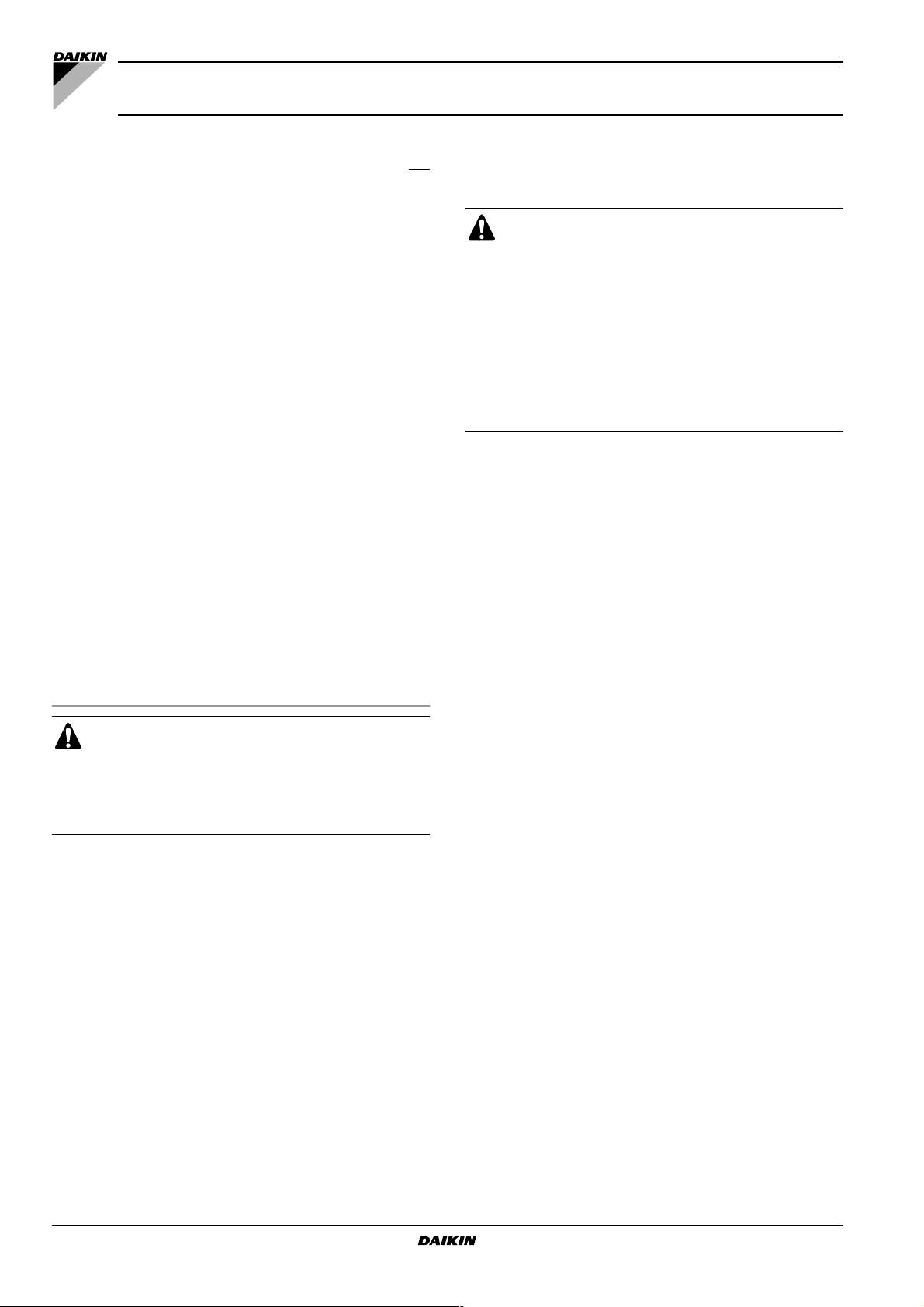
NAMES AND FUNCTIONS OF PARTS (See figure 14)
1
Indoor unit
2
Outdoor unit
3
Remote controller
4
Inlet air
5
Discharged air
6
Refrigerant piping
7
Drain pipe
8 Ground wire
Wire to ground outdoor unit to prevent electrical shocks.
9
Air filter
10
Connection electric wire
■ Never let the indoor unit and the remote controller get
wet.
It may cause an electric shock or a fire.
■ Never use flammable spray such as hair spray,
lacquer or paint near the unit.
It may cause a fire.
■ Never replace a fuse with that of a wrong ampere
rating or other wires when the fuse blows out.
Use of wire or copper wire may cause the unit to
break down or cause a fire.
■ Never insert objects such as sticks into the air inlet or
outlet. It is dangerous for an object to touch the fan
when it is turning at high speed.
■ Never remove the fan grill of the outdoor unit.
The rotating fan at high speed without the guard is
very dangerous.
■ Never inspect or service the unit by yourself.
Ask a qualified service person to perform this work.
IMPORTANT INFORMATION REGARDING THE
REFRIGERANT USED
This product contains fluorinated greenhouse gases covered by the
Kyoto Protocol.
Refrigerant type: R410A
(1)
GWP
value: 1975
(1)
GWP = global warming potential
Periodical inspections for refrigerant leaks may be required
depending on European or local legislation. Please contact your local
dealer for more information.
6 Press Inspection/Test Operation button and operate normally.
7 Confirm function of unit during operation. Refer to the manual of
the remote controller on how to operate.
NOTE
If the main power supply is turned off during operation,
operation will restart automatically after the power
turns back on again.
Precautions
In case something is wrong with the unit and it does not operate,
refer to the malfunction diagnosis label attached to the unit.
FDEQ71~125B8V3B
Split System air conditioners
4PW23693-1A
OPERATION RANGE (See figure 11)
If operating outside the following conditions, safety devices may
activate, rendering the air conditioner inoperable or may cause the
indoor unit to sweat.
The setting temperature range of the remote controller is 16°C - 32°C.
(DB=dry bulb, WB=wet bulb, =cooling, =heating, =indoor,
°
=outdoor, =temperature, =humidity)
C
Installation and operation manual
6
Page 10

OPERATION PROCEDURE
NOT A MALFUNCTION OF THE AIR CONDITIONER
■ If a function that is not available is selected, the
message NOT AVAILABLE will appear.
■ Operating procedure varies with heat pump type and
straight cooling type. Contact your Daikin dealer to
confirm your system type.
■ To protect the unit, turn on the main power switch
6 hours before operation.
■ If the main power supply is turned off during
operation, operation will restart automatically after the
power turns back on again.
Precautions for group control system or two remote controller control system
This system provides two other control systems beside individual
control (one remote controller controls one indoor unit) system.
Confirm the following if your unit is of the following control system
type.
■ Group control system
One remote controller controls up to 16 indoor units.
All indoor units are equally set.
■ Tw o remote controller control system
Tw o remote controllers control one indoor unit (In case of group
control system, one group of indoor units). The unit is
individually operated.
NOTE
Contact your Daikin dealer in case of changing the
combination or setting of group control and two remote
controller control systems.
OPTIMUM OPERATION
Observe the following precautions to ensure the system operates
properly.
■ Adjust the air outlet properly and avoid direct air flow to room
inhabitants.
■ Adjust the room temperature properly for a comfortable
environment. Avoid excessive heating or cooling.
■ Prevent direct sunlight from entering a room during cooling
operation by using curtains or blinds.
■ Keep doors and windows closed. If the doors and windows
remain open, room air will flow out and decrease the effect of
cooling and heating.
■ Never place objects near the air inlet and the air outlet of the
unit. It may retard effectiveness or cause operation to stop.
■ Tu rn off the main power supply switch when not using for long
periods of time. Electricity is consumed as long as the switch is
on. Turn off the main power supply switch in order to save
energy. Turn on the main power supply switch 6 hours before
restarting operation in order to ensure smooth operation. (Refer
to "Maintenance" on page 8.)
■ When the display shows " " (TIME TO CLEAN AIR
FILTER), have a qualified service person to clean the filters.
(Refer to "Maintenance" on page 8.)
The following symptoms do not indicate air conditioner malfunction.
The system does not operate
■ The system does not restart immediately after the ON/OFF
button is pressed.
If the OPERATION lamp lights, the system is in its normal
operating condition.
It does not restart immediately because one of its safety devices
actuates to prevent the system from being overloaded.
The system will turn on again automatically after three minutes.
■ The system does not restart immediately when the
TEMPERATURE SETTING button is returned to its former
position after pushing.
It does not restart immediately because one of its safety devices
actuates to prevent the system from being overloaded.
The system will turn on again automatically after three minutes.
■ The system does not start when the display shows " "
(EXTERNAL CONTROL ICON) and it flashes for a few seconds
after pressing an operation button.
This is because the system is controlled or disabled by another
controller with a higher priority.
When the display flashes, it indicates that the system cannot be
controlled by this indoor unit.
■ The system does not start immediately after the power supply is
turned on.
Wait one minute until the micro computer is prepared for
operation.
White mist comes out of a unit
■ When humidity is high during cooling operation (In oily or dusty
places).
If the inside of an indoor unit is extremely contaminated, the
temperature distribution inside a room becomes uneven. It is
necessary to clean the inside of the indoor unit. Ask your Daikin
dealer for details on cleaning the unit. This operation requires a
qualified service person.
■ When the system is changed over to HEATING OPERATION
after DEFROST OPERATION.
Moisture generated by DEFROST becomes steam and exits.
Noise of air conditioners
■ A continuous low "hissing" sound is heard when the system is in
COOLING or DEFROST OPERATION.
This is the sound of refrigerant gas flowing through both indoor
and outdoor units.
■ A "hissing" sound which is heard at the start or immediately after
the stop of operation or which is heard at the start or
immediately after the stop of DEFROST OPERATION.
This is the noise of refrigerant caused by flow stop and flow
change.
■ A "squeaking" sound is heard when the system is in operation or
after the stop of operation.
Expansion and contraction of plastic parts caused by
temperature change makes this noise.
Dust from the units
■ Dust may blow out from the unit after starting operation from
long resting time. Dust absorbed by the unit blows out.
The units give off odours
■ The unit absorbs the smell of rooms, furniture, cigarettes, etc.,
and then emits them.
Installation and operation manual
7
The liquid crystal display of the remote controller shows " "
■ Happens immediately after the main power supply switch is
turned on.
Shows that the remote controller is in normal condition.
Continues temporarily.
FDEQ71~125B8V3B
Split System air conditioners
4PW23693-1A
Page 11

TROUBLESHOOTING
MAINTENANCE
If one of the following malfunctions occurs, take the measures shown
below and contact your Daikin dealer.
The system must be repaired by a qualified service person.
■ If a safety device such as a fuse, a breaker, or an earth leakage
breaker frequently actuates, or ON/OFF switch does not
properly work.
Measure: Turn off the main power switch.
■ If water leaks from unit.
Measure: Stop the operation.
■ If the display " " (INSPECTION), "UNIT No.", and the
OPERATION lamp flashes and the "MALFUNCTION CODE"
appears.
Measure: Notify your Daikin dealer and inform him/her of the
display.
If the system does not operate properly, except for the above
mentioned case, and none of the above mentioned malfunctions is
evident, investigate the system according to the following
procedures.
If the system does not operate at all.
■ Check if there is a power failure.
Wait until power is restored. If power failure occurs during
operation, the system automatically restarts immediately after
the power supply recovers.
■ Check if the fuse has blown or breaker has been tripped.
Change the fuse or set the breaker.
If the system stops operating after operation is complete.
■ Check if the air inlet or outlet of outdoor or indoor unit is blocked
by obstacles.
Remove the obstacle and make it well-ventilated.
■ Check if the air filter is clogged.
Ask a qualified service person to clean the air filter.
The system operates but it does not sufficiently cool or heat.
■ If the air inlet or outlet of the indoor or the outdoor unit is blocked
with obstacles.
Remove the obstacle and make it well-ventilated.
■ If the air filter is clogged.
Ask a qualified service person to clean the air filter.
■ If the set temperature is not proper. (Refer to the manual of the
remote controller.)
■ If the FAN SPEED CONTROL button is set to LOW SPEED.
(Refer to the manual of the remote controller.)
■ If the doors or the windows are open. Shut doors or windows to
prevent wind from coming in.
■ If direct sunlight enters the room (when cooling).
Use curtains or blinds.
■ When there are too many inhabitants in the room. Cooling effect
decreases if heat gain of the room is too large.
■ If the heat source of the room is excessive (when cooling).
Cooling effect decreases if heat gain of the room is too large.
■ Only a qualified service person is allowed to perform
maintenance.
■ Before obtaining access to terminal devices, all power
supply circuits must be interrupted.
■ Do not use water or air of 50°C or higher for cleaning
air filters and outside panels.
■ When cleaning the heat exchanger, be sure to remove
the switchbox and fan motor. Water or detergent may
deteriorate the insulation of electronic components
and result in burn-out of these components.
How to clean the air filter
Clean the air filter when the display shows " " (TIME TO CLEAN
AIR FILTER).
Increase the frequency of cleaning if the unit is installed in a room
where the air is extremely contaminated.
(As a yardstick for yourself, consider cleaning the filter once a half
year.)
If the dirt becomes impossible to clean, change the air filter. (Air filter
for exchange is optional.)
(See figure 12)
1 Remove the filter holding plate (1) from the bottom plate.
2 Remove the air filter (2) by sliding it downwards.
3 Clean the air filter. (Refer to figure 13 air flow direction over
filter.)
Use vacuum cleaner or wash the air filter with water.
When the air filter is very dirty, use soft brush and neutral
detergent.
Remove water and dry in the shade.
4 Replace the air filter by sliding it between the guiding plates.
5 Replace the filter holding plate to the bottom plate.
6 After turning on the power, press FILTER SIGN RESET button.
The “TIME TO CLEAN AIR FILTER” display is turned off.
FDEQ71~125B8V3B
Split System air conditioners
4PW23693-1A
Installation and operation manual
8
Page 12

How to clean air outlet
■ Clean with soft cloth.
■ When it is difficult to remove stains, use water or neutral
detergent.
NOTES
NOTE
Do not use gasoline, benzene, thinner, polishing
powder, liquid insecticide. It may cause discoloring or
warping.
Do not let the indoor unit get wet. It may cause an
electric shock or a fire.
Start-up after a long stop
■ Confirm the following.
- Check that the air inlet and outlet are not blocked. Remove
any obstacle.
- Check if the earth is connected.
■ Clean the air filter.
- After cleaning the air filter, make sure to attach it.
■ Tu rn on the main power supply switch.
- The control panel display lights when the power is turned on.
-To protect the unit, turn on the main power switch at least
6 hours before operation.
What to do when stopping the system for a long period
■ Tu rn on FAN OPERATION for a half day and dry the unit.
- Refer to the manual of the remote controller.
■ Cut off the power supply.
- When the main power switch is turned on, some wattage is
being consumed even if the system is not operating.
- The remote controller display is turned off when the main
power switch is turned off.
Disposal requirements
Dismantling of the unit, treatment of the refrigerant, of oil and of other
parts must be done in accordance with relevant local and national
legislation.
Your air conditioning product is marked with this symbol.
This means that electrical and electronic products shall
not be mixed with unsorted household waste.
Do not try to dismantle the system yourself: the dismantling of the air
conditioning system, treatment of the refrigerant, of oil and of other
parts must be done by a qualified installer in accordance with
relevant local and national legislation.
Air conditioners must be treated at a specialized treatment facility for
re-use, recycling and recovery. By ensuring this product is disposed
of correctly, you will help to prevent potential negative consequences
for the environment and human health. Please contact the installer or
local authority for more information.
Batteries must be removed from the remote controller and disposed
of separately in accordance with relevant local and national
legislation.
Installation and operation manual
9
FDEQ71~125B8V3B
Split System air conditioners
4PW23693-1A
Page 13

NOTES NOTES
Page 14

Zandvoordestraat 300, B-8400 Oostende, Belgium
4PW23693-1A
 Loading...