

Daikin FCQ71DV3B, FCQ125DV3B, FCQ71DAV3B, FCQ100DV3B, FCQ125DAV3B Installation Manual
...
INSTALLATION MANUAL
SPLIT SYSTEM Air Conditioners
English
Deutsch
MODELS
(Ceiling mounted Multi flow cassette type)
FCQ71DV3B FCQ71DAV3B
FCQ100DV3B FCQ100DAV3B
FCQ125DV3B FCQ125DAV3B
FCQ140DV3B FCQ140DAV3B
READ THESE INSTRUCTIONS CAREFULLY BEFORE INSTALLATION.
KEEP THIS MANUAL IN A HANDY PLACE FOR FUTURE REFERENCE.
LESEN SIE DIESE ANWEISUNGEN VOR DER INSTALLATION SORGFÄLTIG DURCH.
BEWAHREN SIE DIESE ANLEITUNG FÜR SPÄTERE BEZUGNAHME GRIFFBEREIT
AUF.
LIRE SOIGNEUSEMENT CES INSTRUCTIONS AVANT L’INSTALLATION.
CONSERVER CE MANUEL A PORTEE DE MAIN POUR REFERENCE ULTERIEURE.
LEA CUIDADOSAMENTE ESTAS INSTRUCCIONES ANTES DE INSTALAR.
GUARDE ESTE MANUAL EN UN LUGAR A MANO PARA LEER EN CASO DE TENER
ALGUNA DUDA.
PRIMA DELL’INSTALLAZIONE LEGGERE ATTENTAMENTE QUESTE ISTRUZIONI.
TENERE QUESTO MANUALE A PORTATA DI MANO PER RIFERIMENTI FUTURI.
Français
Español
Italiano
ΕλληνικÜ
Nederlands
Portugues
Рóссêий
ÄΙΑΒΑΣΤΕ ΠΡΟΣΕΚΤΙΚΑ ΑΥΤΕΣ ΤΙΣ ΟÄΗΓΙΕΣ ΠΡΙΝ ΑΠΟ ΤΗΝ ΕΓΚΑΤΑΣΤΑΣΗ ΕΧΕΤΕ
ΑΥΤΟ ΤΟ ΕΓΧΕΙΡΙÄΙΟ ΕΥΚΑΙΡΟ ΓΙΑ ΝΑ ΤΟ ΣΥΜΒΟΥΛΕΥΕΣΤΕ ΣΤΟ ΜΕΛΛΟΝ.
LEES DEZE INSTRUCTIES ZORGVULDIG DOOR VOOR INSTALLATIE. BEWAAR DEZE
HANDLEINDING WAAR U HEM KUNT TERUGVINDEN VOOR LATERE NASLAG.
LEIA COM ATENÇÃO ESTAS INSTRUÇÕES ANTES DE REALIZAR A INSTALAÇÃO.
MANTENHA ESTE MANUAL AO SEU ALCANCE PARA FUTURAS CONSULTAS.
ПЕРЕД НАЧАЛОМ МОНТАЖА ВНИМАТЕЛЬНО ОЗНАКОМЬТЕСЬ С ДАННЫМИ
ИНСТРУКЦИЯМИ. СОХРАНИТЕ ДАННОЕ РУКОВОДСТВО В МЕСТЕ, УДОБНОМ ДЛЯ
ОБРАЩЕНИЯ В БУДУЩЕМ.
DAIKIN.TCF.021
KEMA
2024351-QUA/EMC02-4565
Umeda Center Bldg., 4-12, Nakazaki-Nishi 2-chome,
Kita-ku, Osaka, 530-8323 Japan
Noboru Murata
Manager Quality Control Department
Sakai, 1st of October 2005
FCQ71DV3B, FCQ100DV3B, FCQ125DV3B, FCQ140DV3B
DAIKIN INDUSTRIES, LTD.
FCQ71DAV3B, FCQ100DAV3B, FCQ125DAV3B, FCQ140DAV3B
EN60335-2-40,
3P154437-1A
FCQ71DV3B FCQ71DAV3B
FCQ100DV3B FCQ100DAV3B
FCQ125DV3B FCQ125DAV3B
FCQ140DV3B FCQ140DAV3B
SPLIT SYSTEM Air Conditioners Installation manual
CONTENTS
1. SAFETY CONSIDERATIONS ........................................................................................1
2. BEFORE INSTALLATION ..............................................................................................3
3. SELECTING INSTALLATION SITE................................................................................5
4. PREPARATIONS BEFORE INSTALLATION .................................................................6
5. INDOOR UNIT INSTALLATION .....................................................................................8
6. REFRIGERANT PIPING WORK ....................................................................................9
7. DRAIN PIPING WORK .................................................................................................12
8. ELECTRIC WIRING WORK .........................................................................................15
9. WIRING EXAMPLE ......................................................................................................17
10. FIELD SETTING...........................................................................................................19
11. INSTALLATION OF THE DECORATION PANEL .......................................................... 21
12. TEST OPERATION ......................................................................................................21
13. WIRING DIAGRAM ......................................................................................................25
1. SAFETY CONSIDERATIONS
Please read these “SAFETY CONSIDERATIONS” carefully before installing air conditioning equipment and
be sure to install it correctly. After completing the installation, make sure that the unit operates properly during
the start-up operation. Please instruct the customer on how to operate the unit and keep it maintained.
Also, inform customers that they should store this installation manual along with the operation manual for
future reference.
This air conditioner comes under the term “appliances not accesible to the general public”.
Meaning of warning and caution symbols.
WARNING .........Failure to observe a warning may result in death or serious injury.
CAUTION ..........Failure to observe a caution may result in injury or damage to the equipment.
WARNING
• Ask your dealer or qualified personnel to carry out installation work. Do not try to install the air conditioner
yourself.
Improper installation may result in water leakage, electric shocks or fire.
• Perform installation work in accordance with this installation manual.
Improper installation may result in water leakage, electric shocks or fire.
• Be sure to use only the specified accessories and parts for installation work.
Failure to use the specified parts may result in water leakage, electric shocks, fire or the unit falling.
• Install the air conditioner on a foundation strong enough to withstand the weight of the unit.
A foundation of insufficient strength may result in the equipment falling and causing injuries.
• Carry out the specified installation work after considering strong winds, typhoons or earthquakes.
Improper installation work may result in the equipment falling and causing accidents.
English 1
• Make sure that a separate power supply circuit is provided for this unit and that all electrical work is carried
out by qualified personnel according to local laws and regulations and this installation manual.
An insufficient power supply capacity or improper electrical construction may lead to electric shocks or fire.
• Make sure that all wiring is secured, the specified wires and used, and no external forces act on the terminal
connections or wires.
Improper connections or installation may result in fire.
• When wiring the power supply and connecting the wiring between the indoor and outdoor units, position the
wires so that the terminal box lid can be securely fastened.
Improper positioning of the terminal box lid may result in electric shocks, fire or the terminals overheating.
• If the refrigerant gas leaks during installation, ventilate the area immediately.
Toxic gas may be produced if the refrigerant gas comes into contact with fire.
• After completing the installation work, check that the refrigerant gas does not leak.
Toxic gas may be produced if the refrigerant gas leaks into the room and comes into contact with a source
of fire, such as a fan heater, stove or cooker.
• Before touching electrical parts, turn off the unit.
• Be sure to establish an earth.
Do not earth the unit to a utility pipe, arrester, or telephone earth.
Incomplete earth may cause electrical shock, or fire.
A high surge current from lightning or other sources may cause damage to the air conditioner.
• Be sure to install an earth leakage breaker.
Failure to install an earth leakage breaker may result in electric shocks, or fire.
CAUTION
• While following the instructions in this installation manual, install drain piping in order to ensure proper
drainage and insulate piping in order to prevent condensate.
Improper drain piping may result in water leakage and property damage.
• Install the indoor and outdoor units, power supply wiring and connecting wiring at least 1 meter away from
televisions or radios in order to prevent image interference or noise.
(Depending on the radio waves, a distance of 1 meter may not be sufficient enough to eliminate the noise.)
• Remote controller (wireless kit) transmitting distance can result shorter than expected in rooms with electronic fluorescent lamps. (inverter or rapid start types)
Install the indoor unit as far away from fluorescent lamps as possible.
• Do not install the air conditioner in the following locations:
(a) where a mineral oil mist or an oil spray or vapor is produced, for example in a kitchen
Plastic parts may deteriorate and fall off or result in water leakage.
(b) where corrosive gas, such as sulfurous acid gas, is produced
Corroding copper pipes or soldered parts may result in refrigerant leakage.
(c) near machinery emitting electromagnetic waves
Electromagnetic waves may disturb the operation of the control system and result in a malfunction of
the equipment.
(d) where flammable gases may leak, where there are carbon fiber or ignitable dust suspensions in the air,
or where volatile flammables such as thinner or gasoline are handled.
Operating the unit in such conditions may result in fire.
• Make sure to provide for adequate measures in order to prevent that the outdoor unit be used as a shelter
by small animals.
Small animals making contact with electrical parts can cause malfunctions, smoke or fire. Please instruct
the customer to keep the area around the unit clean.
2 English

2. BEFORE INSTALLATION
Do not exert pressure on the resin parts when opening the unit or when moving it after opening
Be sure to check the type of R410A refrigerant to be used before doing any work. (Using an incorrect
refrigerant will prevent normal operation of the unit.)
• When opening the unit or moving it after opening, be sure to lift it by holding on to the lifting lugs without
exerting any pressure on other parts, especially, drain piping, and other resin parts.
• Decide upon a line of transport.
• Leave the unit inside its packaging while moving, until reaching the installation site. Use a sling of soft mate-
rial, where unpacking is unavoidable or protective plates together with a rope when lifting, to avoid damage
or scratches to the unit.
• Refer to the installation manual of the outdoor unit for items not described in this manual.
• Do not dispose of any parts necessary for installation until the installation is complete.
1. PRECAUTIONS
• Be sure to read this manual before installing the indoor unit.
• When selecting installation site, refer to the paper pattern.
• This unit is suitable for installation in a household, commercial and light industrial environment.
• Do not install or operate the unit in rooms mentioned below.
• Laden with mineral oil, or filled with oil vapor or spray like in kitchens. (Plastic parts may deteriorate.)
• Where corrosive gas like sulfurous gas exists. (Copper tubing and brazed spots may corrode.)
• Where volatile flammable gas like thinner or gasoline is used.
• Where machines can generate electromagnetic waves. (Control system may malfunction.)
• Where the air contains high levels of salt such as that near the ocean and where voltage fluctuates
greatly such as that in factories. Also in vehicles or vessels.
2. ACCESSORIES
Check the following accessories are included with your unit.
(3)
Name (1) Drain hose (2) Metal clamp
Quan-
tity
Shape
Name
Quan-
tity
For paper pattern
for installation
Shape
1 pc. 1 pc. 8 pcs. 8 pcs. 1 pc.
(6) Screw
(M5)
4 pcs. 4 pcs. 1 each 1 each 1 pc.
(7) Washer
fixing plate
Insulation for
(8) for gas pipe
Washer for
hanger bracket
fitting
(10) Large
(4) Clamp
Sealing pad
(12) Small
(5) Paper pattern
for installation
Also used as
packing material
(Other)
• Installation
manual
• Operation
manual
(9)
for liquid pipe
English 3
(11) Medium
3. OPTIONAL ACCESSORIES
• The optional decoration panel and remote controller are required for this indoor unit. (Refer to Table 1, 2)
(However, the remote controller is not required for the slave unit of a simultaneous operation system.)
Ta b l e 1
Unit model Optional decoration panel
FCQ71·100·125·140
• These are two types of remote controllers: wired and wireless. Select a remote controller from Table 2
according to customer request and install in an appropriate place.
Ta b l e 2
Remote controller
Wired type BRC1D527, BRC1D528, BRC1C61
Wireless type BRC7E51W, BRC7EA51W
NOTE
• If you wish to use a remote controller that is not listed in “Table 2” on page 4, select a suitable remote con-
troller after consulting catalogs and technical materials.
BYCP125DJW1, BYCP125DAW1
Color : White
FOR THE FOLLOWING ITEMS, TAKE SPECIAL CARE DURING CONSTRUCTION AND
CHECK AFTER INSTALLATION IS FINISHED.
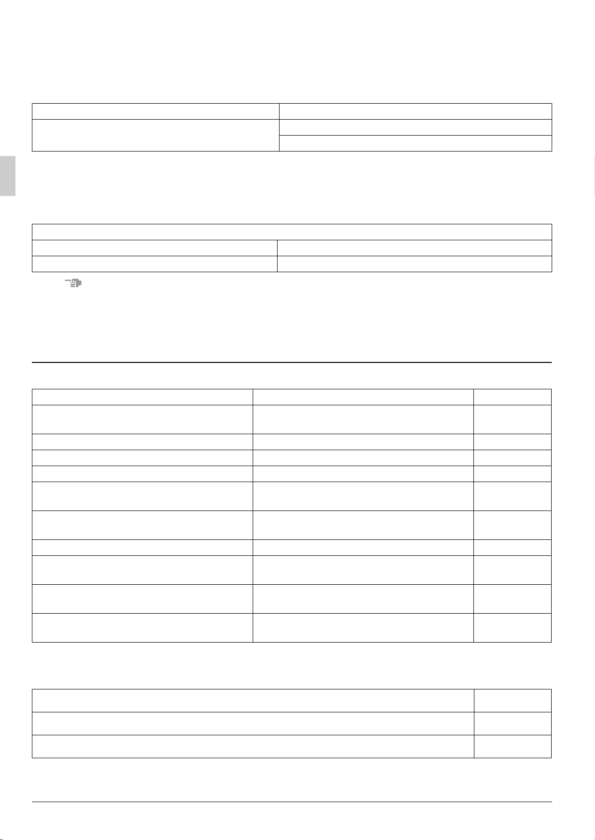
1. Items to be checked after completion of work
Items to be checked If not properly done, what is likely to occur Check
Are the indoor unit and outdoor unit fixed
firmly?
Is the gas leak test finished? It may result in insufficient cooling.
Is the unit fully insulated? Condensate water may drip.
Does drainage flow smoothly? Condensate water may drip.
Does the power supply voltage correspond
to that shown on the name plate?
Are wiring and piping correct?
Is the unit safely grounded? It may result in electric shock.
Is wiring size according to specifications?
Is something blocking the air outlet or inlet
of either the indoor or outdoor units?
Are refrigerant piping length and additional
refrigerant charge noted down?
The unit may drop, vibrate or make noise.
The unit may malfunction or the components burn out.
The unit may malfunction or the components burn out.
The unit may malfunction or the components burn out.
It may result in insufficient cooling.
The refrigerant charge in the system is not
clear.
2. Items to be checked at time of delivery
* Also review the “1. SAFETY CONSIDERATIONS”
Items to be checked Check
Did you explain about operations while showing the instruction manual to your customer?
Did you hand the instruction manual over to your customer?
4 English
Points for explanation about operations
The items with WARNING and CAUTION marks in the instruction manual are the items pertaining to possibilities for bodily injury and material damage in addition to the general usage of
the product. Accordingly, it is necessary that you make a full explanation about the described contents and also ask your customers to read the instruction manual.
4. NOTE TO THE INSTALLER
Be sure to instruct customers how to properly operate the unit (especially cleaning filters, operating different
functions, and adjusting the temperature) by having them carry out operations themselves while looking at the
manual.
3. SELECTING INSTALLATION SITE
Please attach additional thermal insulation material to the unit body when it is believed that the relative humidity in the ceiling exceeds 80%. Use glass wool, polyethylene foam, or similar with a thickness of 10 mm or
more as thermal insulation material.
(1) Select an installation site where the following conditions are fulfilled and that meets your cus-
tomer’s approval.
• In the upper space (including the back of the ceiling) of the indoor unit where there is no possible
dripping of water from the refrigerant pipe, drain pipe, water pipe, etc.
• Where optimum air distribution can be ensured.
• Where nothing blocks air passage.
• Where condensate can be properly drained.
• Where the ceiling is strong enough to bear the indoor unit weight.
• Where the false ceiling is not noticeably on an incline.
• Where sufficient clearance for maintenance and service can be ensured.
• Where there is no risk of flammable gas leakage.
• Where piping between indoor and outdoor units is possible within the allowable limit.
(Refer to the installation manual for the outdoor unit.)
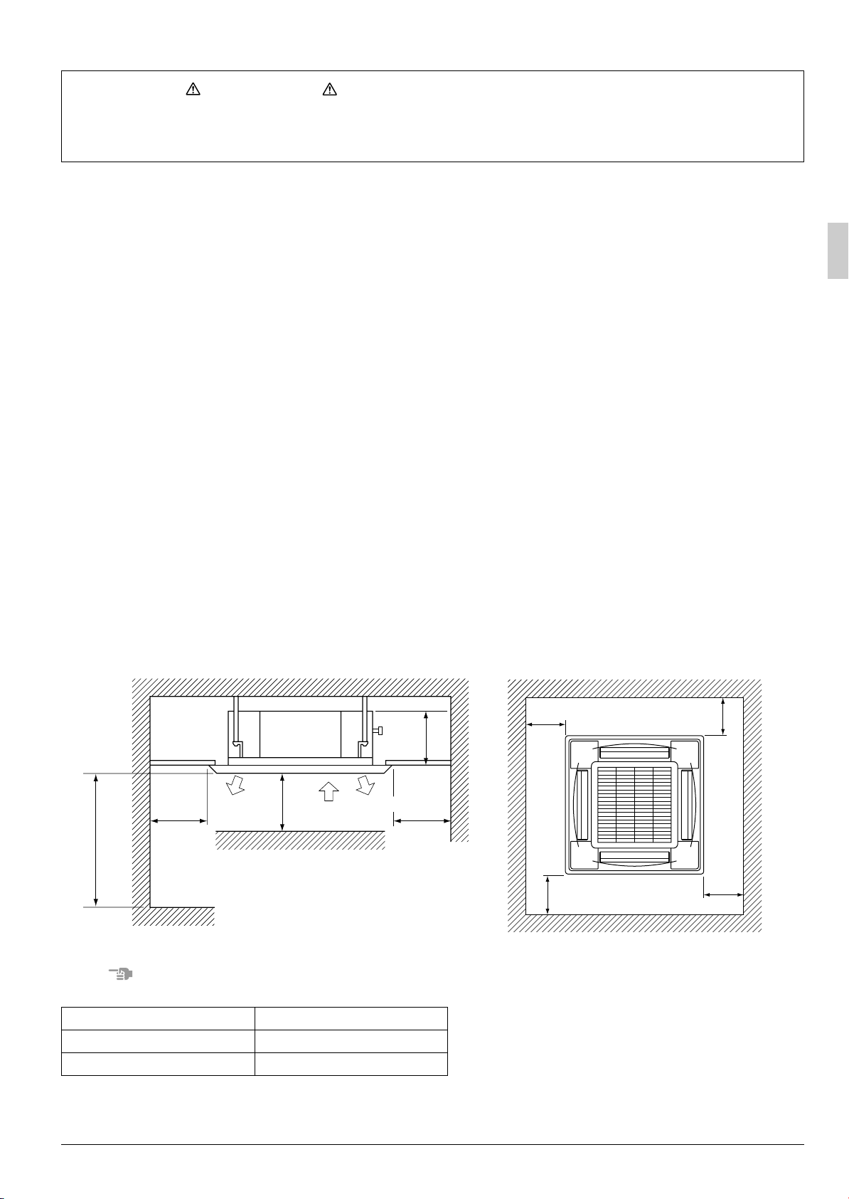
[Space required for installation]
H
*≥
1500
2500
≥
For installation
in high places
NOTE
• Leave 200 mm or more space where marked with the *, on sides where the air outlet is closed.
Model H
FCQ71 256
FCQ100·125·140 298
Air
discharge
1500
≥
Fig. 1
Air discharge
Air
inlet
*≥
1500
*≥1500
*≥1500
*≥1500
*≥1500
Fig. 2
English 5
CAUTION
• Any vents, light fixtures, or other appliances which may disturb the airflow might cause the top side to
become dirty if located too nearby, so follow the figure below when installing.
• Keep indoor unit, outdoor unit, power supply wiring and transmission wiring at least 1 meter away from
televisions and radios. This is to prevent image interference and noise in those electrical appliances.
(Noise may be generated depending on the conditions under which the electric wave is generated, even
if 1 meter is kept.)
(2) Ceiling height
• Install this unit where the height of bottom panel is more than 2.5 m so that the user cannot easily touch.
This indoor unit may be installed on ceilings up to 3.5 m in height. However, it becomes necessary to
•
make field settings by remote controller and close the air outlet when installing the unit at a height over
2.7 m.
Refer to the section entitled, “10. FIELD SETTING” and the decoration panel installation manual.
(3) Use suspension bolts for installation. Check whether the ceiling is strong enough to support the
weight of the unit or not. If there is a risk, reinforce the ceiling before installing the unit.
(Installation pitch is maked on the paper pattern for installation. Refer to it to check for points requiring reinforcing.)
4. PREPARATIONS BEFORE INSTALLATION
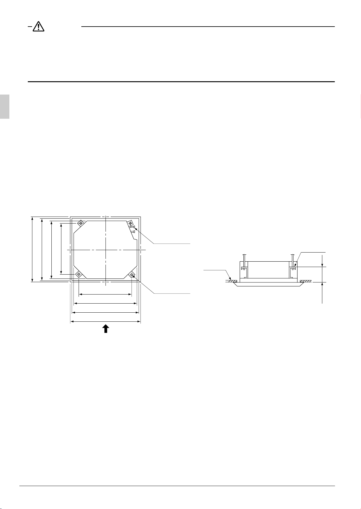
(1) Relation of ceiling opening to unit and suspension bolt position.
Refrigerant
piping
False
840 (Indoor unit)
950 (Decoration panel)
860 – 910 (Ceiling opening)
780 (Suspension bolt pitch)
680(Suspension bolt pitch)
840 (Indoor unit)
860 – 910 (Ceiling opening)
950 (Decoration panel)
Suspension
bolt (×4)
A
Fig. 3
ceiling
View as seen from A
Fig. 4
Hanger
bracket
(150)
6 English

Installation is possible when ceiling opening dimensions is as follows
• When installing the unit within the frame for fixing false ceiling.
860
(Opening dimension inside
Frame
the flame for ceiling)
False
840
910
ceiling
(Dimension inside frame)
≥20
(Ceiling-panel
overlapping dimension)
840
≥20
(Ceiling opening dimension)
860 – *910
910
(Dimension inside frame)
Fig. 5
NOTE
• Installation is possible with a ceiling dimension of 910 mm (marked with *). However, to achieve a ceiling-
panel overlapping dimension of 20 mm, the spacing between the ceiling and the unit should be 35 mm or
less. If the spacing between ceiling and the unit is over 35 mm, attach ceiling material to part or
recover the ceiling.
Fig. 6
Ceiling material
35
≥
35
≥
Fig. 7
(2) Make the ceiling opening needed for installation where applicable. (For existing ceilings)
• Refer to the paper pattern for installation (5) for ceiling opening dimensions.
• Create the ceiling opening required for installation. From the side of the opening to the casing outlet,
implement the refrigerant and drain piping and wiring for remote controller (unnecessary for wireless
type) and indoor-outdoor unit casing outlet. Refer to “6. REFRIGERANT PIPING WORK”, “7. DRAIN
PIPING WORK” and “8. ELECTRIC WIRING WORK”.
• After making an opening in the ceiling, it may be necessary to reinforce ceiling beams to keep the ceiling
level and to prevent it from vibrating. Consult the builder for details.
(3) Install the suspension bolts.
(Use either a M8~M10 size bolt)
Use a hole-in anchor for existing ceilings, and
a sunken insert, sunken anchor or other field
supplied parts for new ceilings to reinforce
the ceiling to bear the weight of the unit.
Adjust clearance (50 – 100 mm) from the
ceiling before proceeding further.
<installation example>
Ceiling slab
Anchor
Long nut or turn-buckle
50 – 100
Suspension bolt
False ceiling
Fig. 8
NOTE
• All the above parts are field supplied.
English 7
 Loading...