

Daikin FFN15CV1, FCN20FV1, FCN25FV1, FCN30FV1, FCN35FV1 Technical Manual
...
TECHNICAL MANUAL
Split Unit Air Conditioner
Ceiling Cassette F & C Series
FCN-F, FFN-C Series
— Cooling only [50Hz] —
R410A
TM-FFCN-0916-B

Table of Contents
i
Table of Contents
Nomenclature......................................................................................................................1
Indoor ............................................................................................................................1
Outdoor ..........................................................................................................................1
Panel .............................................................................................................................2
Product Line-Up .............................................................................................................3
Application Information .....................................................................................................5
Operating Range ...........................................................................................................5
Refrigerant Circuit Diagrams .........................................................................................6
Installation Guideline .....................................................................................................8
Sound Data ........................................................................................................................15
Sound Pressure Level .................................................................................................15
NC Curve .....................................................................................................................16
Engineering & Physical Data ...........................................................................................20
Performance Data .............................................................................................................24
Calculation Steps .........................................................................................................24
Performance Tables .....................................................................................................27
Outline & Dimension ........................................................................................................36
Wiring Diagram .................................................................................................................39
Service & Maintenance ....................................................................................................43
Troubleshooting ...............................................................................................................45
Nomenclature
1
Nomenclature
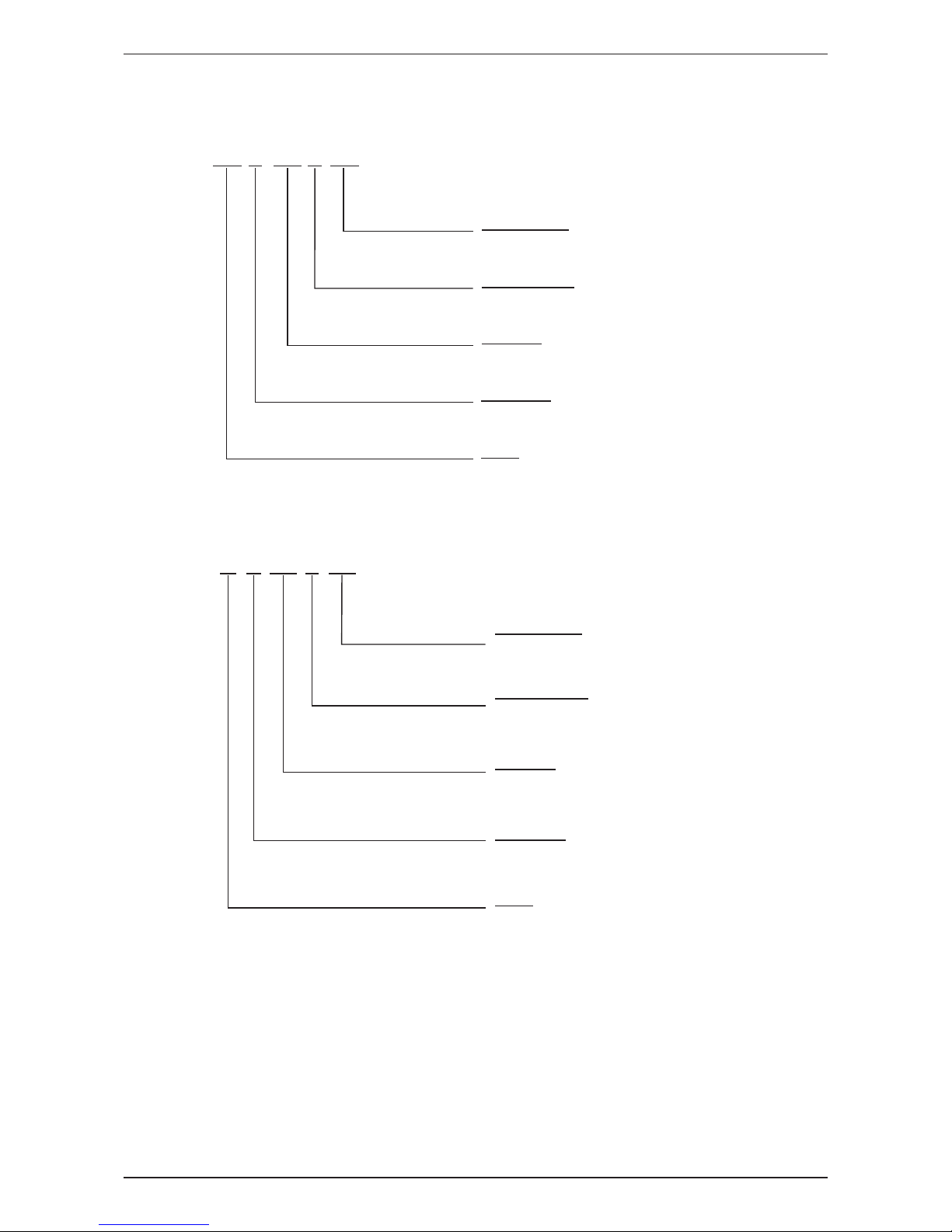
Indoor
30 FFC N V1
Power Supply
V: 220-240V 1 Phase 50 Hz
Product Series
F: F series
C: C Series
Capacity*
30: 30,000Btu/hr
Refrigerant
N: R410A
Model
FC: Ceiling Cassette 3”x3”
FF: Ceiling cassette 2”x2”
Outdoor
30 CR N V1
Power Supply
V1: 220-240V 1 Phase 50Hz
Y1: 380-415V 3 Phase 50Hz
Product Series
C: C Series
D: D Series
F: F Series
Capacity*
30: 30,000Btu/hr
Refrigerant
N: R410A
Model
R: Single Split Condensing Unit
Remark:
* : Capacity value under Nomenclature is an indication.
Please refer to Engineering and Physical Data for exact capacity value.
Nomenclature
2
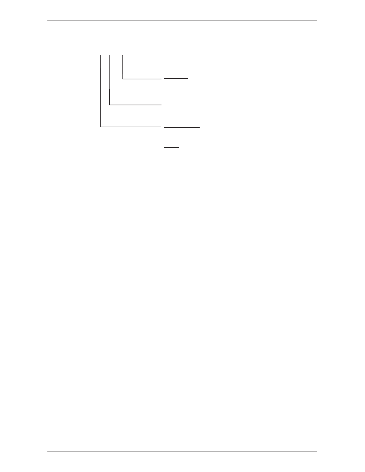
Panel
BC F L G1
Controller
G1: Wireless handset DGS01
2B5: Wireless handset BRC52B65
S8: Wired handset DSLM8
Product Series
F: F Series
C: C series
Model
BC: Ceiling Cassette Panel
BF: Ceiling Cassette Panel
Cool Light
“-”: Without LED Light
L: With LED Light
Nomenclature
3
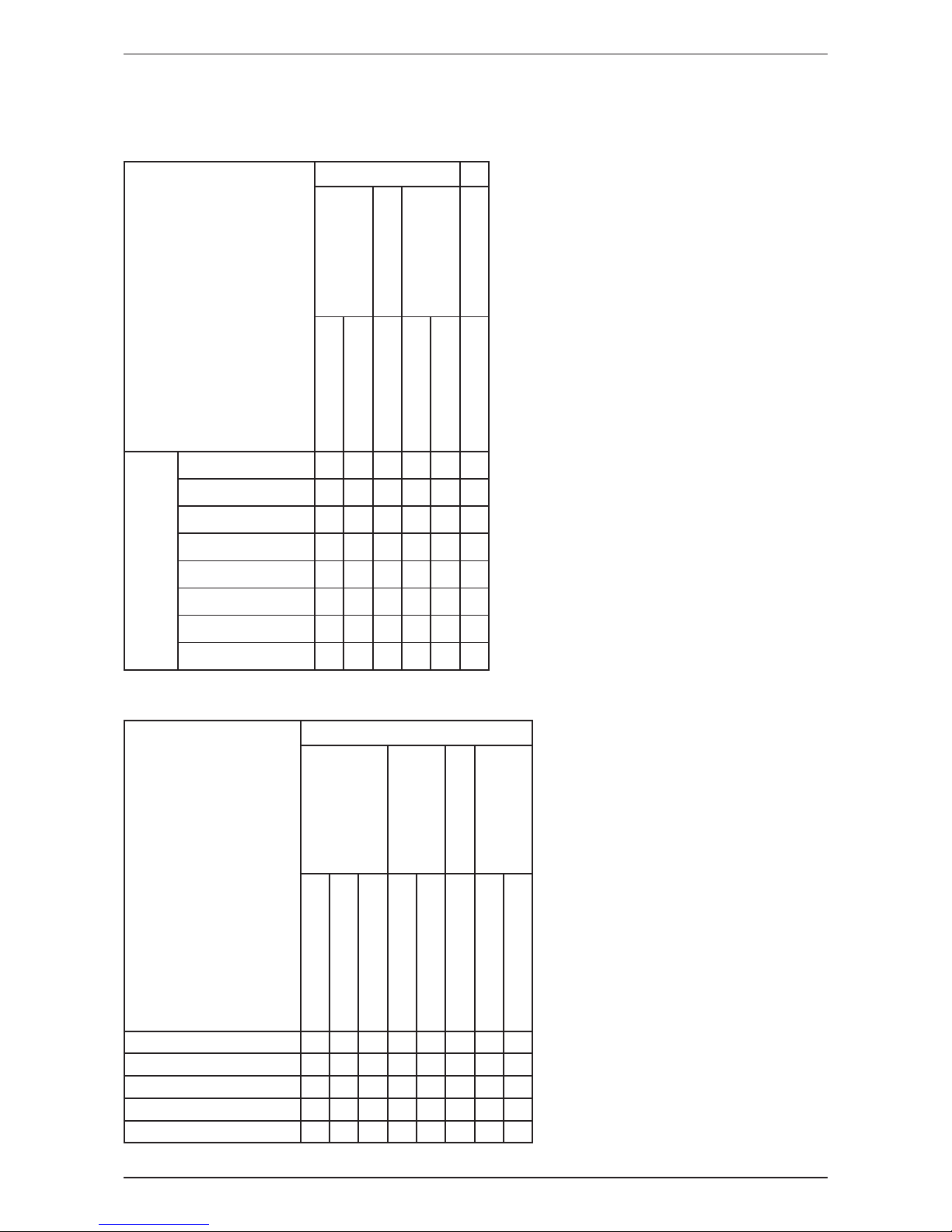
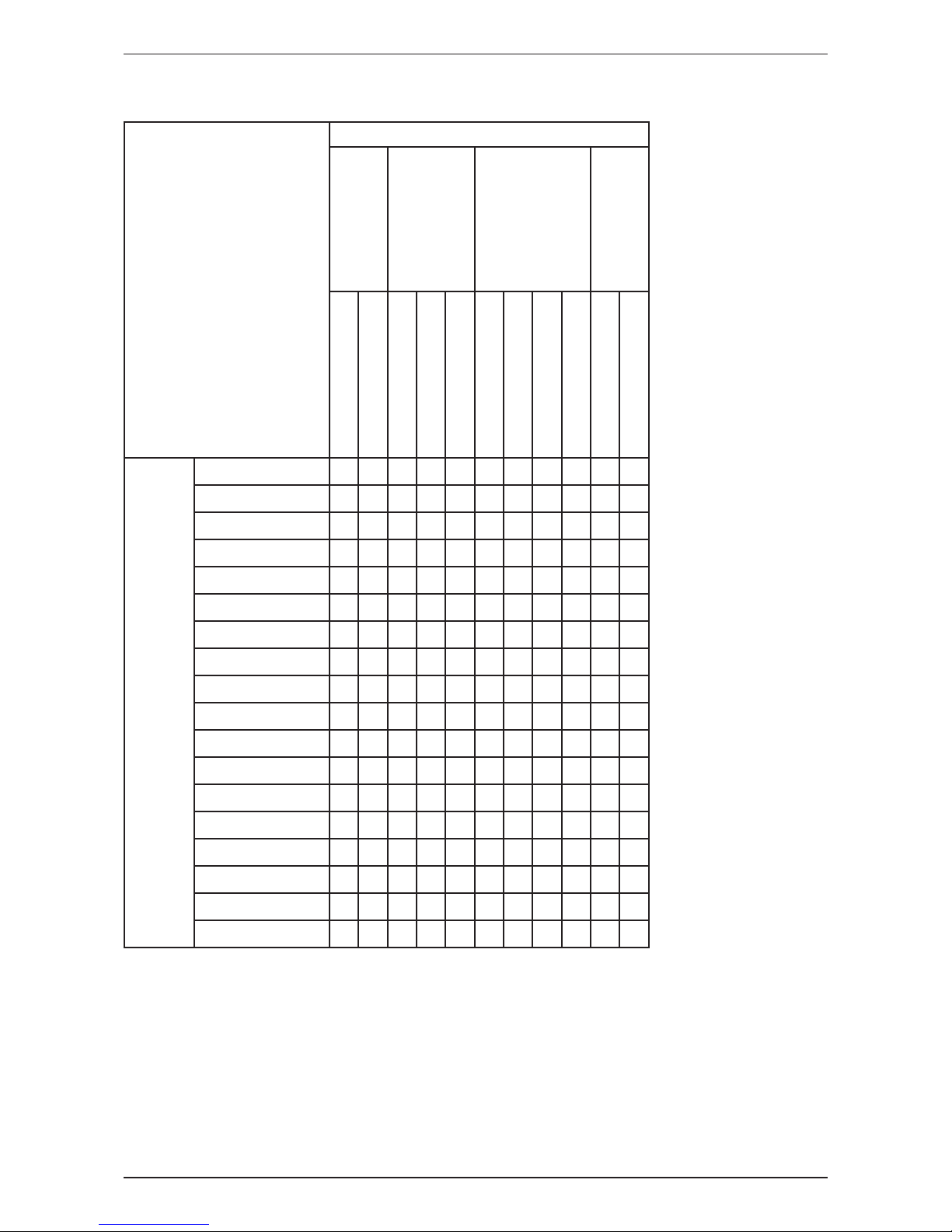
Product Line-Up
Indoor Unit
FCN-F, FFN-C
Nomenclature
Classication
PCB
Fin
Refrigerant
Control
Indoor Air Quality
L208D EC
L208A AP
Hydrophilic (Blue)
Cap Tube
w/o Cap Tube
Plasma
COOLING
FFN10CV1 X X X X
FFN15CV1 X X X X
FCN20FV1 X X X X
FCN25FV1 X X X X
FCN30FV1 X X X X
FCN35FV1 X X X X
FCN40FV1 X X X X
FCN50FV1 X X X X
Panel
BC-F
Nomenclature
Classication
Handset
Cool Light
Indoor Air Quality
Others
DGS01
BRC52B65
DSLM8
With LED Light
W/O LED Light
Saranet Filter
8 Ways Discharge
4 Way Discharge
BFCG1 X X X X
BFCS8 X X X X
BCFG1 X X X X
BCFL2B5 X X X X
BCFS8 X X X X
Nomenclature
4
Outdoor Unit
RN-C/D, RN-F
Nomenclature
Classication
Refrigerant Control
Fin
Safety Devices
Compressor
Cap Tube
TXV
Hydrophilic (Blue)
Hydrophilic (Gold)
Bare Aluminium
Contactor
High Pressure Switch
Low Pressure Switch
Phase Protector
Scroll
Rotary
COOLING
RN10FV1 X X X
RN15FV1 X X X
RN20CV1 X X X
RN25CV1 X X X
RN28CV1 X X X
RN30CV1 X X X
RN35DV1 X X X X X X
RN40DY1 X X X X X X
RN50DY1 X X X X X X
RN10FGV1 X X X
RN15FGV1 X X X
RN20CGV1 X X X
RN25CGV1 X X X
RN28CGV1 X X X
RN30CGV1 X X X
RN35DGV1 X X X X X X
RN40DGY1 X X X X X X
RN50DGY1 X X X X X X

5
Application Information
Application Information
Operating Range
Ensure the operating temperature is in allowance range.
Cooling
The use of your air conditioner
outside the range of working
temperature and humidity can
result in serious failure.
Outdoor
DB (°C)
46
43
19
14 19 23 Indoor WB (°C)
6
Application Information
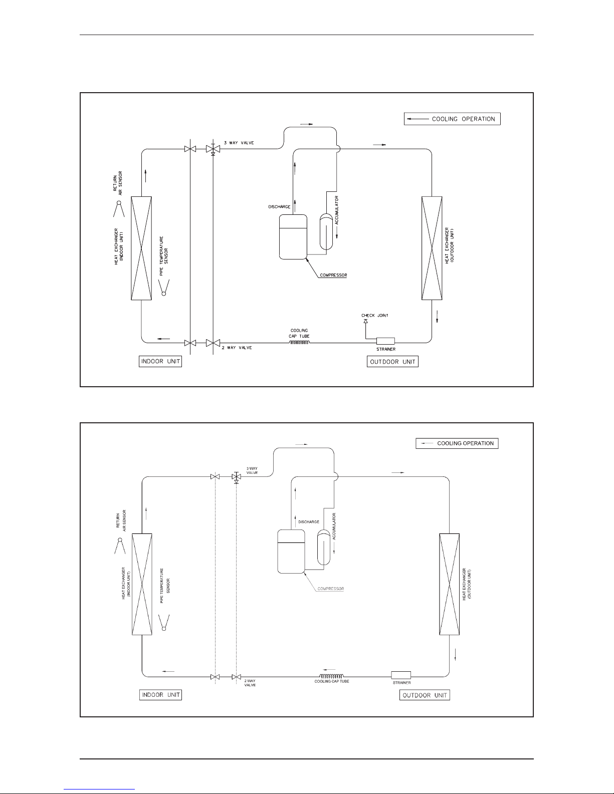
Refrigerant Circuit Diagrams
Model: FFN10/15CV1 - RN10/15FV1
Model: FCN20FV1 - RN20CV1 / FCN25FV1 - RN25CV1

7
Application Information
Model: FCN30FV1 - RN28/30CV1
Model: FCN35FV1 - RN35DV1 / FCN40FV1 - RN40DY1 / FCN50FV1 - RN50DY1
8
Application Information
Installation Guideline
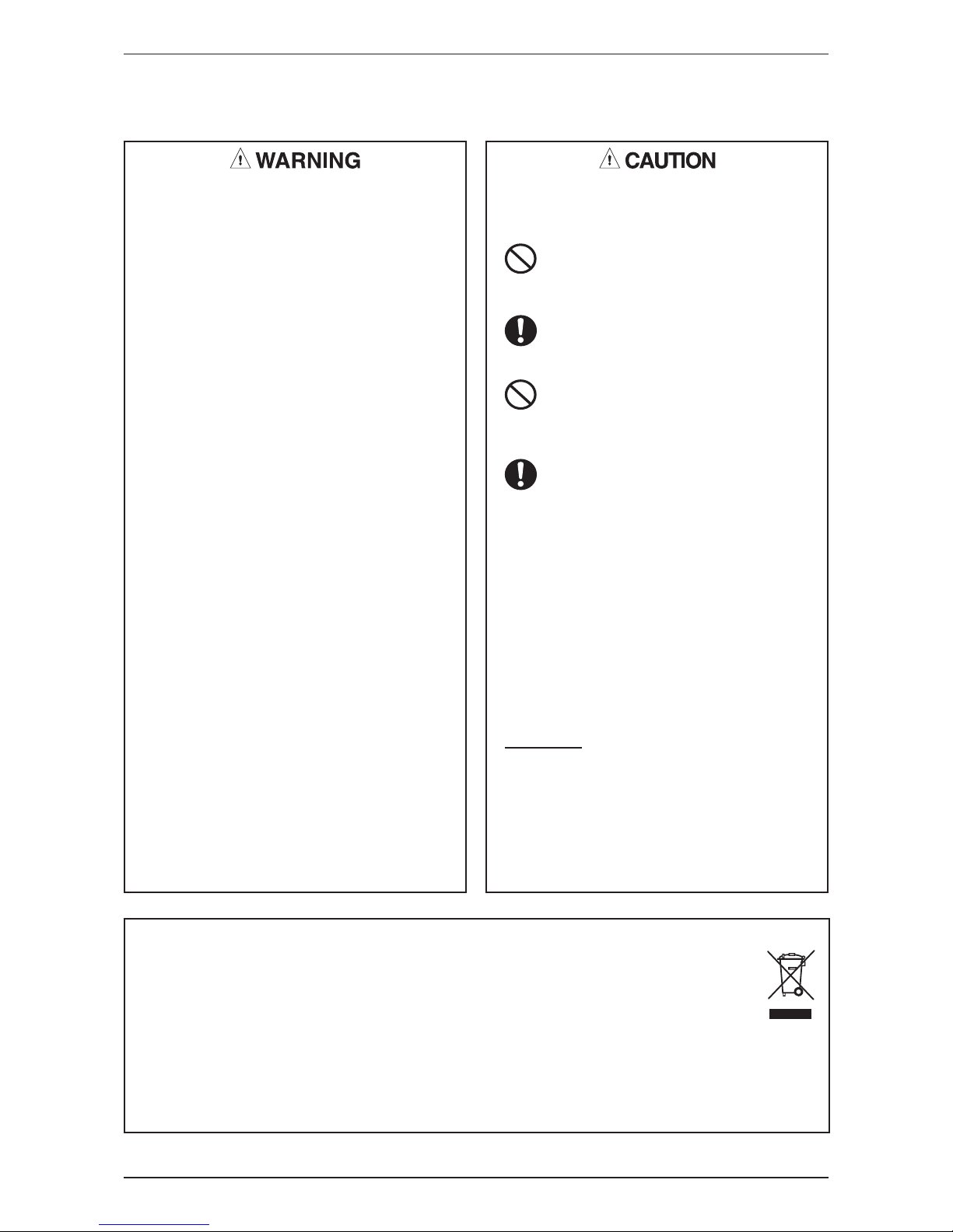
Safety Precautions
• Installation and maintenance should be performed
by qualied persons who are familiar with local code
and regulation, and experienced with this type of
appliance.
• All eld wiring must be installed in accordance with
the national wiring regulation.
• Ensure that the rated voltage of the unit corresponds
to that of the name plate before commencing wiring
work according to the wiring diagram.
• The unit must be GROUNDED to prevent possible
hazard due to insulation failure.
• All electrical wiring must not touch the refrigerant
piping or any moving parts of the fan motors.
• Conrm that the unit has been switched OFF before
installing or servicing the unit.
• Disconnect from the main power supply before
servicing the air conditioner unit.
• DO NOT pull out the power cord when the power is
ON. This may cause serious electrical shocks which
may result in re hazards.
• Keep the indoor and outdoor units, power cable and
transmission wiring, at least 1m from TVs and radios,
to prevent distorted pictures and static. {Depending on
the type and source of the electrical waves, static may
be heard even when more than 1m away}.
Please take note of the following important points
when installing.
• Do not install the unit where leakage of ammable
gas may occur.
If gas leaks and accumulates around the unit, it
may cause re ignition.
• Ensure that drainage piping is connected properly.
If the drainage piping is not connected properly,
it may cause water leakage which will dampen
the furniture.
• Do not overcharge the unit.
This unit is factory pre-charged. Overcharge will
cause over-current or damage to the compressor.
• Ensure that the unit’s panel is closed after service
or installation.
Unsecured panels will cause the unit to operate
noisily.
• Sharp edges and coil surfaces are potential
locations which may cause injury hazards. Avoid
from being in contact with these places.
• Before turning off the power supply, set the remote
controller’s ON/OFF switch to the “OFF” position
to prevent the nuisance tripping of the unit. If this is
not done, the unit’s fans will start turning automatically
when power resumes, posing a hazard to service
personnel or the user.
• Do not operate any heating apparatus too close to the
air conditioner unit. This may cause the plastic panel to
melt or deform as a result of the excessive heat.
• Ensure the color of wires of the outdoor unit and
the terminal markings are same to the indoors
respectively.
• IMPORTANT : DO NOT INSTALL OR USE THE AIR
CONDITIONER UNIT IN A LAUNDRY ROOM.
• Do not use joined and twisted wires for incoming
power supply.
NOTICE
Disposal requirements
Your air conditioning product is marked with this symbol. This means that electrical and electronic products
shall not be mixed with unsorted household waste.
Do not try to dismantle the system yourself: the dismantling of the air conditioning system, treatment of the
refrigerant, of oil and of other parts must be done by a qualied installer in accordance with relevant local and
national legislation. Air conditioners must be treated at a specialized treatment facility for re-use, recycling
and recovery. By ensuring this product is disposed of correctly, you will help to prevent potential negative
consequences for the environment and human health. Please contact the installer or local authority for more
information.
Batteries must be removed from the remote controller and disposed of separately in accordance with relevant
local and national legislation.
9
Application Information
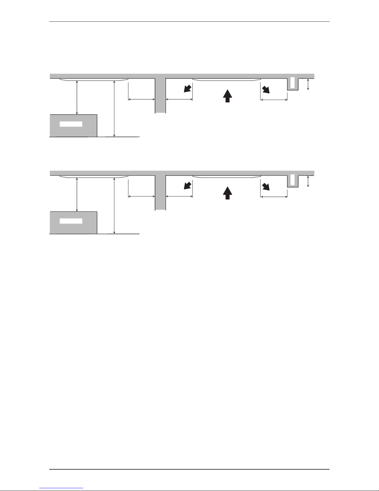
1) Indoor Installation Clearance
Clearance must be provided for the indoor unit from wall and obstacles as shown in gure below.
F series
Beam
0.3m or more
3.0m or more
0.5m or more 0.5m or more 0.5m or more
Floor
Obstacles
1.0m or more
The installation place (handling ceiling surface) must be level and the height in the ceiling is 370mm or more.
C series
Beam
0.3m or more
3.0m or more
0.5m or more 0.5m or more 0.5m or more
Floor
Obstacles
1.0m or more
The installation place (handling ceiling surface) must be level and the height in the ceiling is 350mm or more.
10
Application Information
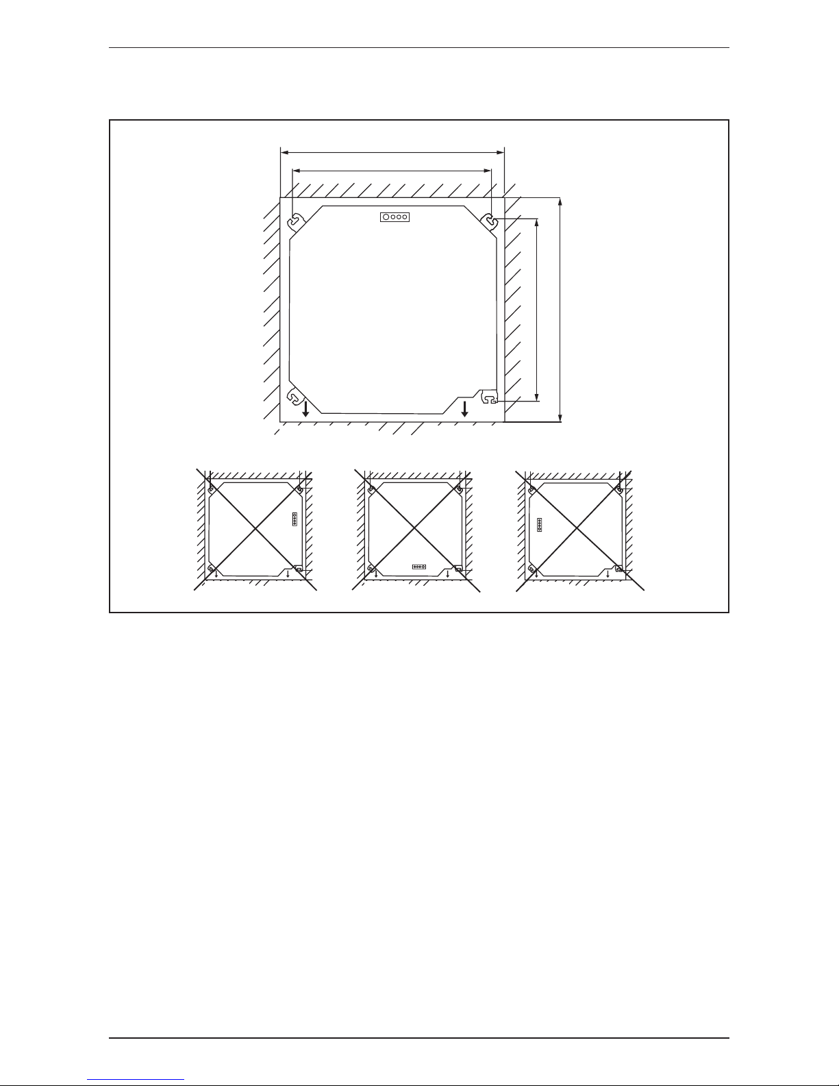
Unit Installation
F series
Ceiling Opening Size = 890mm
Hanging rod size = 780mm
Ceiling Opening Size = 890mm
Hanging rod size = 710mm
WATER DRAINAGE
PIPING DIRECTION
LED
REFRIGERANT
PIPING DIRECTION
WATER DRAINAGE
PIPING DIRECTION
REFRIGERANT
PIPING DIRECTION
LED
WATER DRAINAGE
PIPING DIRECTION
LED
REFRIGERANT
PIPING DIRECTION
WATER DRAINAGE
PIPING DIRECTION
LED
REFRIGERANT
PIPING DIRECTION
11
Application Information
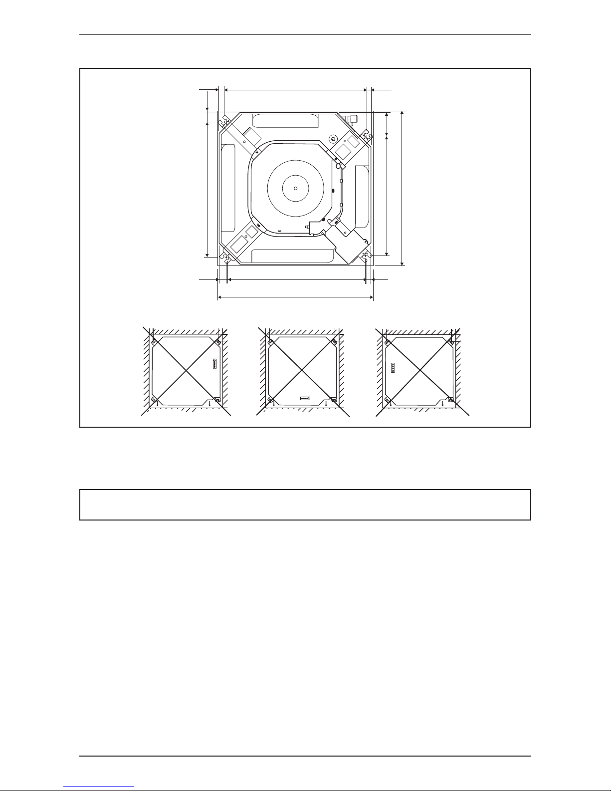
C series
WATER DRAINAGE
PIPING DIRECTION
REFRIGERANT
PIPING DIRECTION
LED
WATER DRAINAGE
PIPING DIRECTION
LED
REFRIGERANT
PIPING DIRECTION
WATER DRAINAGE
PIPING DIRECTION
LED
REFRIGERANT
PIPING DIRECTION
538.0
18.0
32.0 529.0
580.0 ~ 610.0mm (CEILING OPENING MEASUREMENT)
580.0 ~ 610.0mm (CEILING OPENING MEASUREMENT)
505.0
448.0
38.0
15.0
19.0
88.0
All dimensions are in mm
• Measure and mark the position for the hanging rod. Drill the hole for the angle nut on the ceiling and x the hanging
rod.
• The installation template is extended according to temperature and humidity. Check on dimensions in use.
• The dimensions of the installation template are the same as those of the ceiling opening dimensions.
• Before ceiling laminating work is completed, be sure to t the installation template to the indoor unit.
NOTE
Be sure to discuss the ceiling drilling work with the installers concerned.
12
Application Information
Unit Installation
F Series C Series
Indoor Unit
Ceiling Board
38mm
570 (UNIT SIZE)
30
250
All dimensions are in mm
• Hold the unit and hang it on the hanging rod with the nut and washer.
• Adjust the unit height to 38mm and 30mm respectively depending on series between the indoor unit bottom surface
and the ceiling surface.
• Conrm with a level gauge that the unit is installed horizontally and tighten the nut and bolt to prevent unit falling and
vibration.
• Open the ceiling board along the outer edge of the paper installation template.
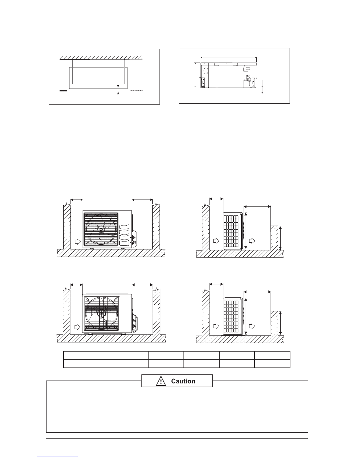
2) Outdoor Installation Clearance
Outdoor unit must be installed such that there is no short circuit of the hot discharge air or obstruction to smooth
air ow. Select the coolest possible place where intake air should not hotter than the outside temperature
(Max. 45°C).
RN10/15FV1
Return air
Service access
C
D
Obstacle
Obstacle
Return air
Discharge air
A
Obstacle
Obstacle
B
H/2
H
RN20/25/30/35DV1, RN40/50DY1
Obstacle
Return air
Service access
DC
Obstacle
Return air
Discharge air
A
Obstacle
Obstacle
B
H/2
H
Dimensions A B C D
Minimum Distance, mm 300 1000 300 500
Avoid installing or operating the condensing unit in the environment that is exposed to the
following substances:
• Oils (including machine oils)
• Salt (e.g. coastal area)
• Sulphide gas (e.g. hot spring areas, oil renery plant, etc)
Such substance may lead to the failure of the unit.
13
Application Information
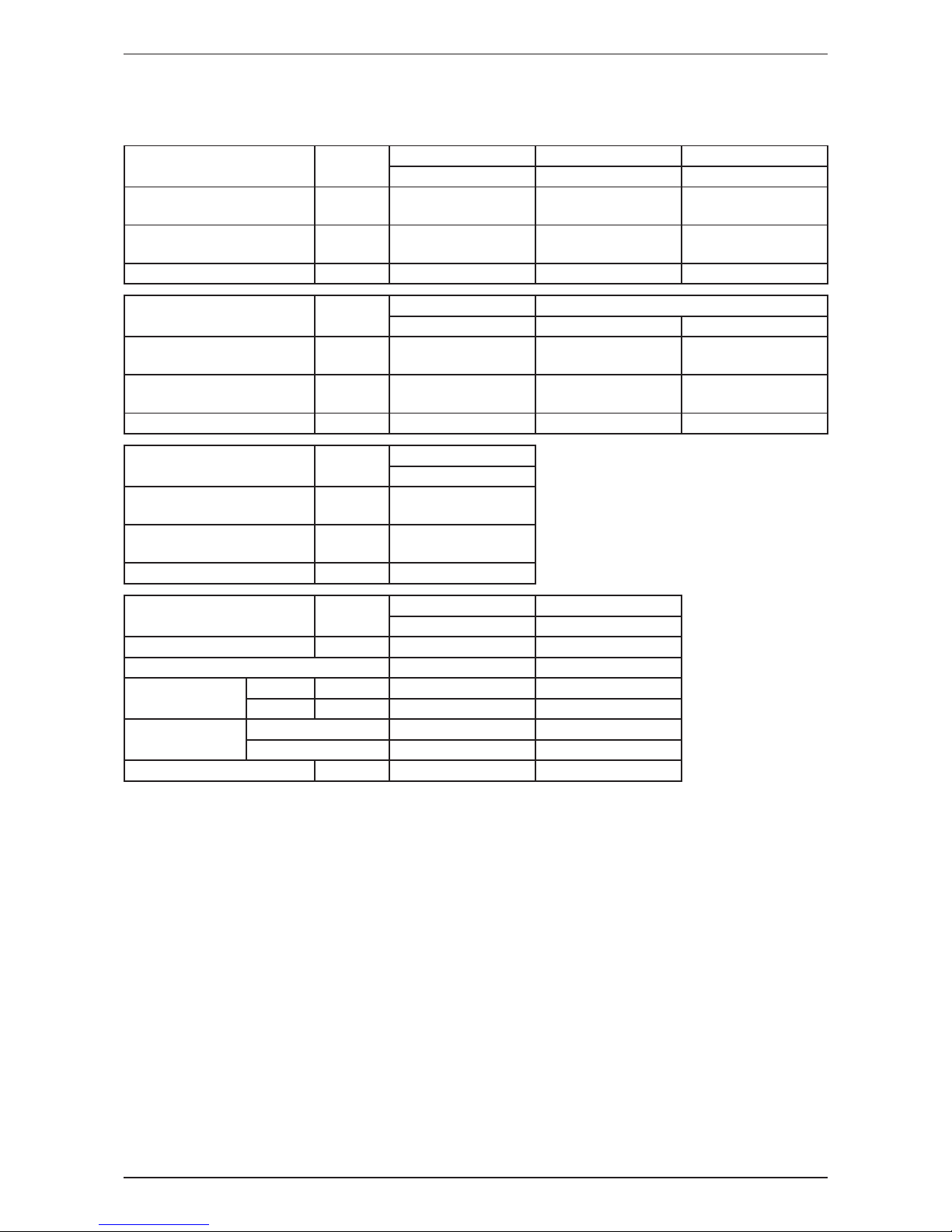
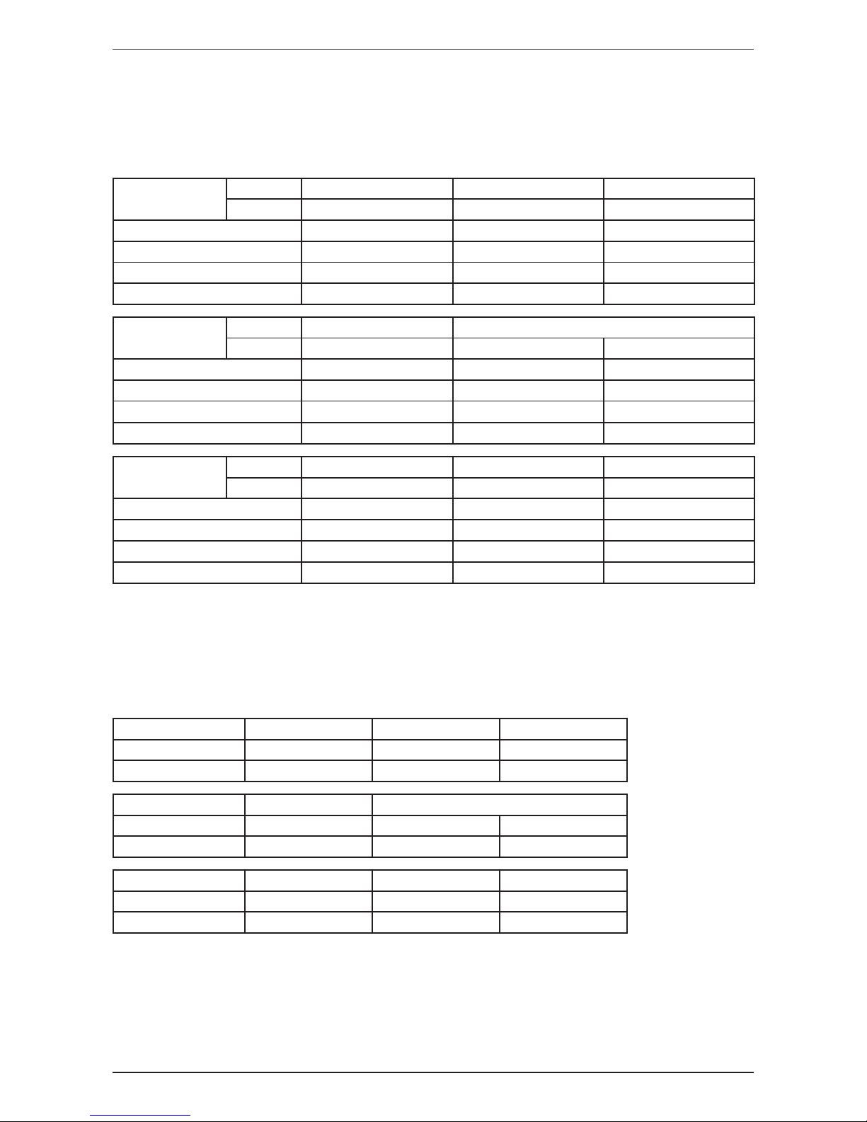
3) Cable Size
Cooling only
Model Unit
FFN10CV1 FFN15CV1 FCN20FV1
RN10FV1 RN15FV1 RN20CV1
Power supply cable size
Number of wire
mm²
1.5
3
1.5
3
2.5
3
Interconnection cable size
Number of wire
mm²
1.5
3
1.5
3
2.5
3
Recommended fuse A 15 15 16
Model Unit
FCN25FV1 FCN30FV1
RN25CV1 RN28CV1 RN30CV1
Power supply cable size
Number of wire
mm
2
2.5
3
2.5
3
2.5
3
Interconnection cable size
Number of wire
mm
2
2.5
3
2.5
3
2.5
3
Recommended fuse A 20 25 25
Model Unit
FCN35FV1
RN35DV1
Power supply cable size
Number of wire
mm
2
4.0
3
Interconnection cable size
Number of wire
mm
2
2.5
4
Recommended fuse A 25
Model Unit
FCN40FV1 FCN50FV1
RN40DY1 RN50DY1
Power supply cable size mm
2
4.0 4.0
Number of wire 3 3
Interconnection
cable size
Indoor mm
2
2.5 2.5
Outdoor mm
2
2.5 2.5
Number of wire
Indoor 4 4
Outdoor 4 + 3 4 + 3
Recommended fuse A 16 20
14
Application Information
4) Refrigerant Piping
When the pipe length becomes too long, both the capacity and reliability drop. As the number of bends
increase, resistance to ow of refrigerant system increases, thus lowering cooling capacity and as a result
the compressor may become defective. Always choose the shortest path and follow the recommendation as
tabulated below:
Model
Indoor FFN10CV1 FFN15CV1 FCN20FV1
Outdoor RN10FV1 RN15FV1 RN20CV1
Max. allowable length, m 20 20 30
Max. allowable elevation, m 10 10 15
Liquid pipe size, mm / in 6.35 / 1/4” 6.35 / 1/4” 6.35 / 1/4”
Gas pipe size, mm / in 9.52 / 3/8” 12.70 / 1/2” 12.70 / 1/2”
Model
Indoor FCN25FV1 FCN30FV1
Outdoor RN25CV1 RN28CV1 RN30CV1
Max. allowable length, m 30 25 45
Max. allowable elevation, m 15 8 25
Liquid pipe size, mm / in 6.35 / 1/4” 9.52 / 3/8” 9.52 / 3/8”
Gas pipe size, mm / in 15.88 / 5/8” 15.88 / 5/8” 15.88 / 5/8”
Model
Indoor FCN35FV1 FCN40FV1 FCN50FV1
Outdoor RN35DV1 RN40DY1 RN50DY1
Max. allowable length, m 50 50 50
Max. allowable elevation, m 30 30 30
Liquid pipe size, mm / in 9.52 / 3/8” 9.52 / 3/8” 9.52 / 3/8”
Gas pipe size, mm / in 15.88 / 5/8” 15.88 / 5/8” 15.88 / 5/8”
5) Additional Charge
• The refrigerant charge has already charged into the outdoor unit. For the piping length of 7.5m, additional
refrigerant charge after vacuuming is not necessary.
• When the piping length is more than 7.5m, please use the table below (unit in gram).
Cooling Only
Indoor
FFN10CV1 FFN15CV1
FCN20FV1
Outdoor RN10FV1 RN15FV1 RN20CV1
Add. Charge, g/m 18 18 22
Indoor FCN25FV1 FCN30FV1
Outdoor RN25CV1 RN28CV1 RN30CV1
Add. Charge, g/m 10 24 24
Indoor FCN35FV1 FCN40FV1 FCN50FV1
Outdoor RN35DV1 RN40DY1 RN50DY1
Add. Charge, g/m 27 24 24
Example: FCN25FV1 & RN25CV1 with 13m piping length, additional piping length is 5.5m. Thus,
Additional Charge = 5.5m x 10 g/m
= 55g
 Loading...