

Daikin ERSQ 016AAV1, ERRQ 011AAV1, ERSQ 016AAY1, ERSQ 014AAV1, ERSQ 011AAY1 Service Manual
...
ESIE09-08
Service Manual
Daikin ALTHERMA HT
ERSQ 011/014/016 AAV1, AAY1
ERRQ 011/014/016 AAV1, AAY1
EKHBRD 011/014/016 AAV1, AAY1
R-410A, R-134a
EKHTS 200/260 A
EKHTSU 200/260 A


ESIE09-08
Table of Contents i
Table of Contents
Table of Contents ............................................................................i
1. Introduction .............................................................................................v
1.1 Safety Cautions ........................................................................................v
1.2 PREFACE ............................................................................................... ix
Part 1 - General Information ..........................................................1
1. Model Names of Indoor/Outdoor Units & Tanks .....................................2
Part 2 - Specifications.................................................................... 5
1. Specifications ..........................................................................................6
1.1 Outdoor Units ...........................................................................................6
1.2 Indoor Unit................................................................................................8
Part 3 - Refrigerant Circuit & Functional Parts ........................... 11
1. Refrigerant Circuit .................................................................................12
1.1 Outdoor Unit ...........................................................................................12
1.2 Indoor Unit..............................................................................................14
2. Functional Parts Layout ........................................................................16
2.1 ERRQ 011/014/016 AAV1, ERSQ 011/014/016 AAV1 ..........................16
2.2 ERRQ 011/014/016 AAY1, ERSQ 011/014/016 AAY1 ..........................18
2.3 EKHBRD 011/014/016 AAV1, EKHBRD 011/014/016 AAY1 .................20
2.4 EKHTS 200/260 A ..................................................................................22
2.5 EKHTSU 200/260 A ...............................................................................24
Part 4 - Electrical Circuit ............................................................. 27
1. Switch Box Layout - Indoor Unit EKHBRD............................................28
2. PCB Layout for EKHBRD 011/014/016 AAV1.......................................30
2.1 Main PCB - A1P .....................................................................................30
2.2 Control - PCB - A3P ...............................................................................32
2.3 Inverter PCB - A4P.................................................................................34
2.4 Filter PCB - A6P .....................................................................................37
2.5 QA PCB - A5P........................................................................................39
2.6 Inverter Control PCB - Three Phase - A4P ............................................40
2.7 Inverter PCB - Three Phase - A5P .........................................................42
2.8 Digital I/O PCB (Option PCB A7P) .........................................................44
2.9 Demand PCB (Option PCB A8P) ...........................................................46
Part 5 - Function ........................................................................... 47
1. Operation Mode ....................................................................................48
2. Basic Control.........................................................................................49
2.1 Normal Operation ...................................................................................49

ESIE09-08
ii Table of Contents
2.2 Compressor PI Control...........................................................................50
2.3 Electronic Expansion Valve PI Control R-410A circuit ...........................51
2.4 Electronic Expansion Valve PI Control R-134a circuit............................51
3. Special Control......................................................................................52
3.1 Startup Control .......................................................................................52
3.2 Defrosting Operation ..............................................................................53
3.3 Pump-down Residual Operation ............................................................54
3.4 Stopping Operation ................................................................................55
4. Protection Control .................................................................................56
4.1 High Pressure Protection Control...........................................................56
4.2 Low Pressure Protection Control............................................................58
4.3 Discharge Pipe Protection Control .........................................................60
4.4 Inverter Protection Control .....................................................................61
5. Other Control.........................................................................................63
5.1 Heating Operation Prohibition ................................................................63
5.2 Inverter Fan Control (Switch Box Fan) ...................................................63
5.3 Crankcase Heater ..................................................................................63
6. Outline of Control (Indoor Unit) .............................................................64
6.1 Freeze Prevention ..................................................................................64
6.2 Simultaneous demand of space heating and domestic water heating ...65
Part 6 - Test Operation................................................................. 71
1. Test Operation ......................................................................................72
1.1 Procedure and Outline ...........................................................................72
1.2 Air Tight Test and Vacuum Drying .........................................................74
1.3 Additional Refrigerant Charge ................................................................75
1.4 Operation when Power is Turned On .....................................................79
2. Outdoor Unit PC Board Layout .............................................................80
3. Field Setting ..........................................................................................81
3.1 Field Setting from remote control ...........................................................81
3.2 Field Setting from Outdoor Unit............................................................104
Part 7 - Troubleshooting............................................................. 115
1. Symptom-based Troubleshooting .......................................................117
2. Troubleshooting by Remote Control ...................................................119
2.1 The INSPECTION / TEST Button.........................................................119
2.2 Self-diagnosis by Wired Remote Control .............................................120
2.3 Operation of the Remote Controller’s Inspection / Test Operation
Button ...................................................................................................121
2.4 Remote Control Service Mode .............................................................122
2.5 Remote Controller Self-Diagnosis Function .........................................124
3. Troubleshooting by Indication on the Remote Controller ....................130
3.1 “A1” Indoor Unit: PC Board Defect.......................................................130
3.2 “A6” Indoor Unit: Pump Error (M1P) or Other Water System Error ......131
3.3 “A9” Indoor Unit: Malfunction of Moving Part of Electronic Expansion
Valve (K1E) R-410A circuit...................................................................132
3.4 “AJ” Indoor Unit: Malfunction of Capacity Determination Device .........134
3.5 “C1” Indoor Unit: Failure of Transmission (Between Indoor unit PC Board
and Control PC Board) .........................................................................135
3.6 “C4” Indoor Unit: Malfunction of Thermistor (R3T) Liquid Thermistor R-

ESIE09-08
Table of Contents iii
410A .....................................................................................................137
3.7 “C5” Indoor Unit: Malfunction of Tank Thermistor (R2T)......................138
3.8 “C9” Indoor Unit: Return Water Thermistor (R4T) ................................139
3.9 “CA” Indoor Unit: Leaving Water Thermistor Error (R5T).....................140
3.10 “CJ” Indoor Unit: Malfunction of Thermostat Sensor in Remote
Controller..............................................................................................141
3.11 “E1” Outdoor Unit: PC Board Defect ....................................................142
3.12 “E1” Indoor Unit: PC Board Defect.......................................................143
3.13 “E3” Outdoor Unit: Actuation of High Pressure Switch.........................144
3.14 “E3” Indoor Unit: Actuation of High Pressure Switch............................146
3.15 “E4” Outdoor Unit: Actuation of Low Pressure Sensor.........................149
3.16 “E4” Indoor Unit: Actuation of Low Pressure Sensor............................151
3.17 “E5” Outdoor Unit: Inverter Compressor Motor Lock............................153
3.18 “E5” Indoor Unit: Inverter Compressor Motor Lock ..............................154
3.19 “E7” Malfunction of Outdoor Unit Fan Motor ........................................155
3.20 “E9” Outdoor Unit: Malfunction of Moving Part of Electronic Expansion
Valve ....................................................................................................157
3.21 “E9” Indoor Unit: Malfunction of Moving Part of Electronic Expansion
Valve (K2E) R-134a circuit ...................................................................159
3.22 “F3” Outdoor Unit: Abnormal Discharge Pipe Temperature .................161
3.23 “F3” Indoor Unit: Abnormal Discharge Pipe Temperature....................162
3.24 “H9” Outdoor Unit: Malfunction of Thermistor (R1T) for Outdoor Air....163
3.25 “J3” Outdoor Unit: Malfunction of Discharge Pipe Thermistor (R2T)....164
3.26 “J3” Indoor Unit: Malfunction of Discharge Pipe Thermistor (R6T) ......165
3.27 “J5” Outdoor Unit: Malfunction of Thermistor (R3T, R5T) for Suction Pipe
1, 2 .......................................................................................................166
3.28 “J5” Indoor Unit: Malfunction of Thermistor (R7T) for Liquid R-134a ...167
3.29 “J6” Outdoor Unit: Malfunction of Thermistor (R6T) for Outdoor Unit Heat
Exchanger ............................................................................................168
3.30 “J7” Outdoor Unit: Malfunction of Thermistor (R7T) for Outdoor Unit Liquid
Pipe ......................................................................................................169
3.31 “J9” Outdoor Unit: Malfunction of Thermistor (R4T) for Subcooling Heat
Exchanger Gas Pipe ............................................................................170
3.32 “JA” Outdoor Unit: Malfunction of High Pressure Sensor.....................171
3.33 “JA” Indoor Unit: Malfunction of High Pressure Sensor........................172
3.34 “JC” Outdoor Unit: Malfunction of Low Pressure Sensor .....................173
3.35 “JC” Indoor Unit: Malfunction of Low Pressure Sensor ........................174
3.36 “L1” Outdoor Unit: Malfunction of PC Board.........................................175
3.37 “L1” Indoor Unit: Malfunction of PC Board ...........................................176
3.38 “L4” Outdoor Unit: Malfunction of Inverter Radiating Fin Temperature
Rise ......................................................................................................177
3.39 “L4” Indoor Unit: Malfunction of Inverter Radiating Fin Temperature Rise
(R8T) ....................................................................................................178
3.40 “L5” Outdoor Unit: Inverter Compressor Abnormal -
R-410A .................................................................................................179
3.41 “L5” Indoor Unit: Inverter Compressor Abnormal -
R-134a..................................................................................................180
3.42 “L8” Outdoor Unit: Inverter Current Abnormal......................................181
3.43 “L8” Indoor Unit: Inverter Current Abnormal.........................................182
3.44 “L9” Outdoor Unit: Inverter Start up Error.............................................183
3.45 “L9” Indoor Unit: Inverter Start up Error................................................184
3.46 “LC” Outdoor Unit: Malfunction of Transmission between Inverter and
Control PC Board .................................................................................185

ESIE09-08
iv Table of Contents
3.47 “LC” Indoor Unit: Malfunction of Transmission between Inverter and Con-
trol PC Board........................................................................................186
3.48 “LH” Indoor Unit: Converter Error .........................................................187
3.49 “P1” Outdoor Unit: High Voltage of Capacitor in Main Inverter Circuit .188
3.50 “P1” Indoor Unit: High Voltage of Capacitor in Main Inverter Circuit....189
3.51 “PJ” Indoor Unit: Faulty Combination of PCB.......................................190
3.52 “U0” Low Pressure Drop Due to Refrigerant Shortage or Electronic Expan-
sion Valve Failure.................................................................................191
3.53 “U2” Power Supply Insufficient or Instantaneous Failure .....................193
3.54 “U2” Power Supply Insufficient or Instantaneous Failure .....................195
3.55 “U4” Malfunction of Transmission between Indoor Unit and Outdoor
Unit .......................................................................................................197
3.56 “U4” Malfunction of Transmission Indoor Unit ......................................199
3.57 “U5” Malfunction of Transmission between Remote Control and Indoor
Unit .......................................................................................................200
3.58 “U7” Indoor Unit: Malfunction of Transmission Outdoor Unit................201
3.59 “U8” Malfunction of Transmission between Main and Sub Remote
Controls ................................................................................................202
3.60 “UA” Communication Error between Outdoor Unit and Indoor Unit .....203
3.61 “UF” System is not Set yet ...................................................................204
3.62 “UH” Malfunction of System, Refrigerant System Address Undefined .205
Part 8 - Appendix ........................................................................ 209
1. Piping Diagrams..................................................................................210
1.1 Outdoor Unit .........................................................................................210
1.2 Indoor Unit............................................................................................212
1.3 Switch Box Layout................................................................................214
2. Wiring Diagrams..................................................................................216
2.1 Outdoor Unit .........................................................................................216
2.2 Field Wiring Connection Diagram.........................................................220
2.3 Indoor Unit............................................................................................221
3. Thermistor Resistance / Temperature Characteristics........................229
4. Pressure Sensor .................................................................................232
5. Method of Replacing the Inverter’s Power Transistors Modules.........233
Part 9 - Precautions for New Refrigerant (R-410A) ................... 237
1. Precautions for New Refrigerant (R-410A) .........................................238
1.1 Outline ..................................................................................................238
1.2 Refrigerant Cylinders............................................................................240
1.3 Service Tools........................................................................................241
Index ................................................................................................ i
Drawings & Flow Charts ...............................................................iii
ESIE09-08 Introduction
v
1. Introduction
1.1 Safety Cautions
Cautions and
Warnings
Be sure to read the following safety cautions before conducting repair work.
The caution items are classified into “ Warning” and “ Caution”. The “ Warning”
items are especially important since they can lead to death or serious injury if they are not
followed closely. The “ Caution” items can also lead to serious accidents under some
conditions if they are not followed. Therefore, be sure to observe all the safety caution items
described below.
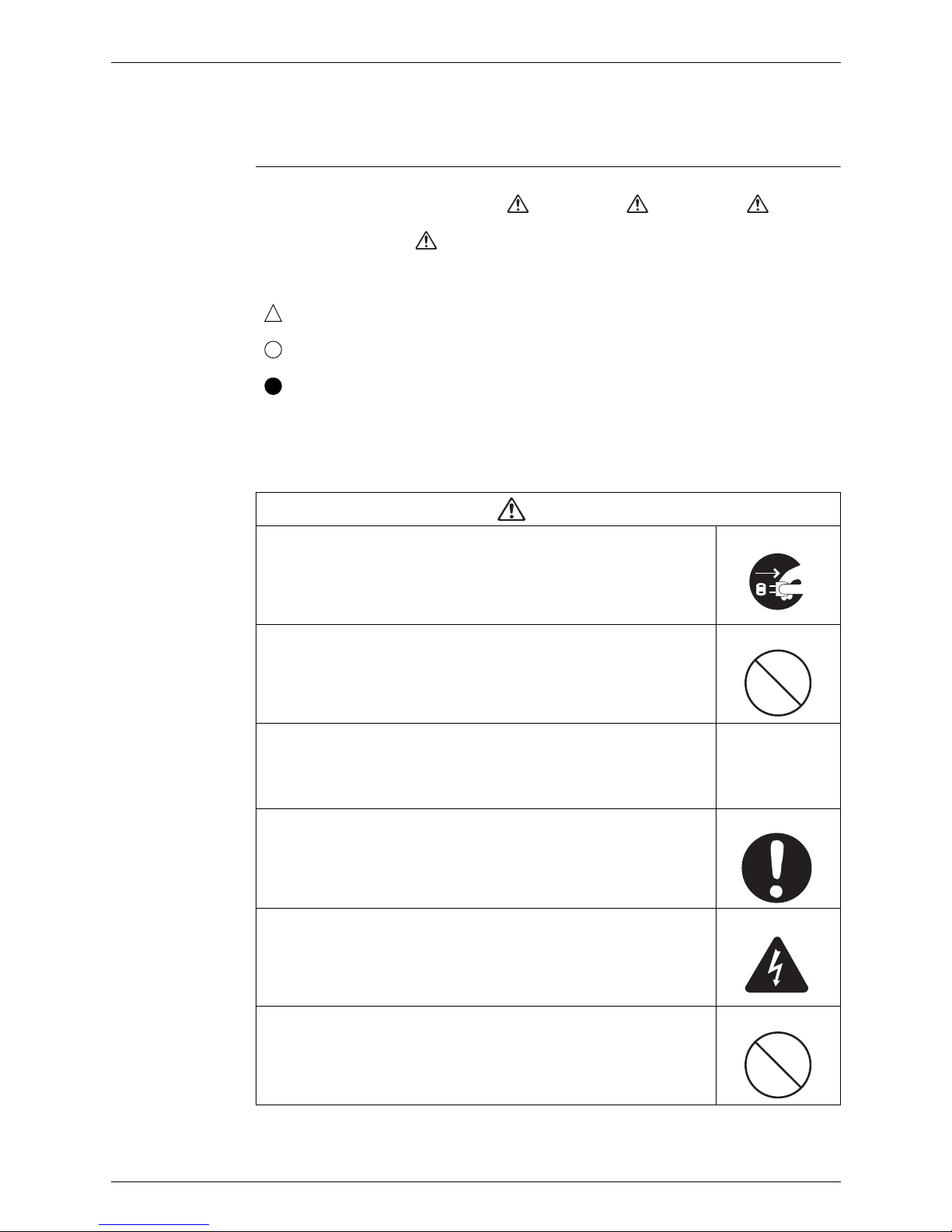
About the pictograms
This symbol indicates an item for which caution must be exercised.
The pictogram shows the item to which attention must be paid.
This symbol indicates a prohibited action.
The prohibited item or action is shown inside or near the symbol.
This symbol indicates an action that must be taken, or an instruction.
The instruction is shown inside or near the symbol.
After the repair work is complete, be sure to conduct a test operation to ensure that the
equipment operates normally, and explain the cautions for operating the product to the
customer
1.1.1 Caution in Repair
Warning
Be sure to disconnect the power cable plug from the plug socket before
disassembling the equipment for a repair.
Working on the equipment that is connected to a power supply can cause an
electrical shock.
If it is necessary to supply power to the equipment to conduct the repair or
inspecting the circuits, do not touch any electrically charged sections of the
equipment. Be careful as the capacitors (top surfaces) can hold up to 220V.
If the refrigerant gas discharges during the repair work, do not touch the
discharging refrigerant gas.
The refrigerant gas can cause frostbite.
When disconnecting the suction or discharge pipe of the compressor at the
welded section, release the refrigerant gas completely at a well-ventilated
place first.
If there is a gas remaining inside the compressor, the refrigerant gas or
refrigerating machine oil discharges when the pipe is disconnected, and it can
cause injury.
If the refrigerant gas leaks during the repair work, ventilate the area. The
refrigerant gas can generate toxic gases when it contacts flames.
The step-up capacitor supplies high-voltage electricity to the electrical
components of the outdoor unit and indoor unit.
Be sure to discharge the capacitor completely before conducting repair work.
A charged capacitor can cause an electrical shock as the capacitors (top
surfaces) can hold up to 220V.
Do not start or stop the heat pump operation by plugging or unplugging the
power cable plug.
Plugging or unplugging the power cable plug to operate the equipment can
cause an electrical shock or fire.
Introduction ESIE09-08
vi
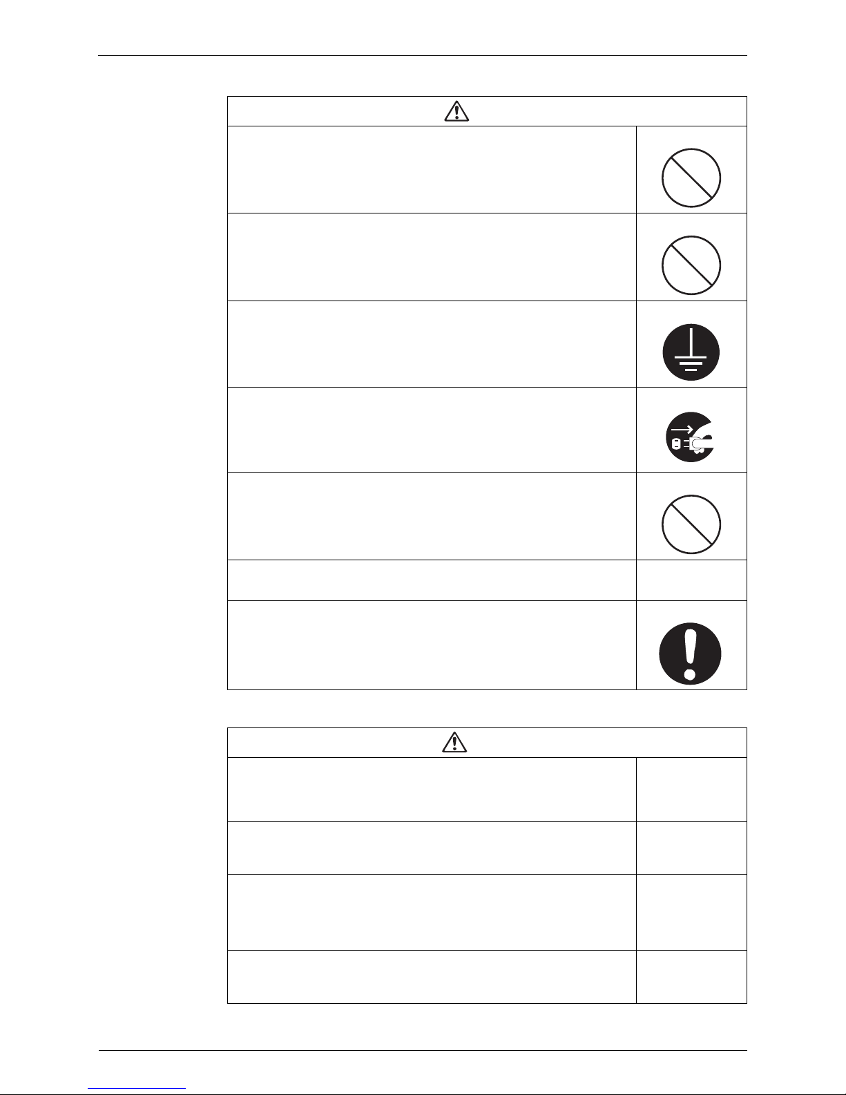
1.1.2 Cautions Regarding Products after Repair
Caution
Do not repair the electrical components with wet hands.
Working on the equipment with wet hands can cause an electrical shock.
Do not clean the heat pump by splashing water.
Washing the unit with water can cause an electrical shock.
Be sure to provide the grounding when repairing the equipment in a humid or
wet place, to avoid electrical shocks.
Be sure to turn off the power switch and unplug the power cable when cleaning
the equipment.
The internal fan rotates at a high speed, and cause injury.
Do not tilt the unit when removing it.
The water inside the unit can spill and wet the furniture and floor.
Be sure to check that the refrigerating cycle section has cooled down
sufficiently before conducting repair work.
Working on the unit when the refrigerating cycle section is hot can cause burns.
Use the welder in a well-ventilated place.
Using the welder in an enclosed room can cause oxygen deficiency.
Warning
Be sure to use parts listed in the service parts list of the applicable model and
appropriate tools to conduct repair work. Never attempt to modify the
equipment.
The use of inappropriate parts or tools can cause an electrical shock,
excessive heat generation or fire.
When relocating the equipment, make sure that the new installation site has
sufficient strength to withstand the weight of the equipment.
If the installation site does not have sufficient strength and if the installation
work is not conducted securely, the equipment can fall and cause injury.
Be sure to use an exclusive power circuit for the equipment, and follow the
technical standards related to the electrical equipment, the internal wiring
regulations and the instruction manual for installation when conducting
electrical work.
Insufficient power circuit capacity and improper electrical work can cause an
electrical shock or fire.
Be sure to use the specified cable to connect between the indoor and outdoor
units. Make the connections securely and route the cable properly so that there
is no force pulling the cable at the connection terminals.
Improper connections can cause excessive heat generation or fire.
ESIE09-08 Introduction
vii
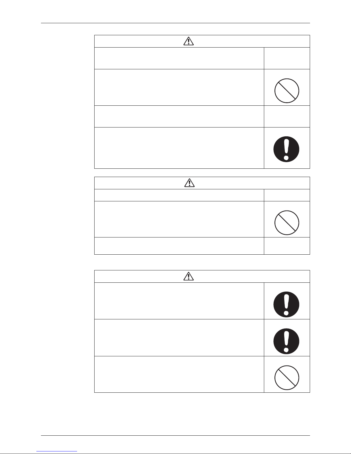
1.1.3 Inspection after Repair
When connecting the cable between the indoor and outdoor units, make sure
that the terminal cover does not lift off or dismount because of the cable.
If the cover is not mounted properly, the terminal connection section can cause
an electrical shock, excessive heat generation or fire.
Do not damage or modify the power cable.
Damaged or modified power cable can cause an electrical shock or fire.
Placing heavy items on the power cable, and heating or pulling the power cable
can damage the cable.
Do not mix air or gas other than the specified refrigerant (R-410A / R-134a) in
the refrigerant system.
If air enters the refrigerating system, an excessively high pressure results,
causing equipment damage and injury.
If the refrigerant gas leaks, be sure to locate the leak and repair it before
charging the refrigerant. After charging refrigerant, make sure that there is no
refrigerant leak.
If the leak cannot be located and the repair work must be stopped, be sure to
perform pump-down and close the service valve, to prevent the refrigerant gas
from leaking into the room. The refrigerant gas itself is harmless, but it can
generate toxic gases when it contacts flames, such as fan and other heaters,
stoves and ranges.
Warning
Caution
Installation of a leakage breaker is necessary in some cases depending on the
conditions of the installation site, to prevent electrical shocks.
Do not install the equipment in a place where there is a possibility of
combustible gas leaks.
If a combustible gas leaks and remains around the unit, it can cause a fire.
Be sure to install the packing and seal on the installation frame properly.
If the packing and seal are not installed properly, water can enter the room and
wet the furniture and floor.
For integral units
only
Warning
Check to make sure that the power cable plug is not dirty or loose, then insert
the plug into a power outlet all the way.
If the plug has dust or loose connection, it can cause an electrical shock or fire.
If the power cable and lead wires have scratches or deteriorated, be sure to
replace them.
Damaged cable and wires can cause an electrical shock, excessive heat
generation or fire.
Do not use a joined power cable or extension cable, or share the same power
outlet with other electrical appliances, since it can cause an electrical shock,
excessive heat generation or fire.
Introduction ESIE09-08
viii
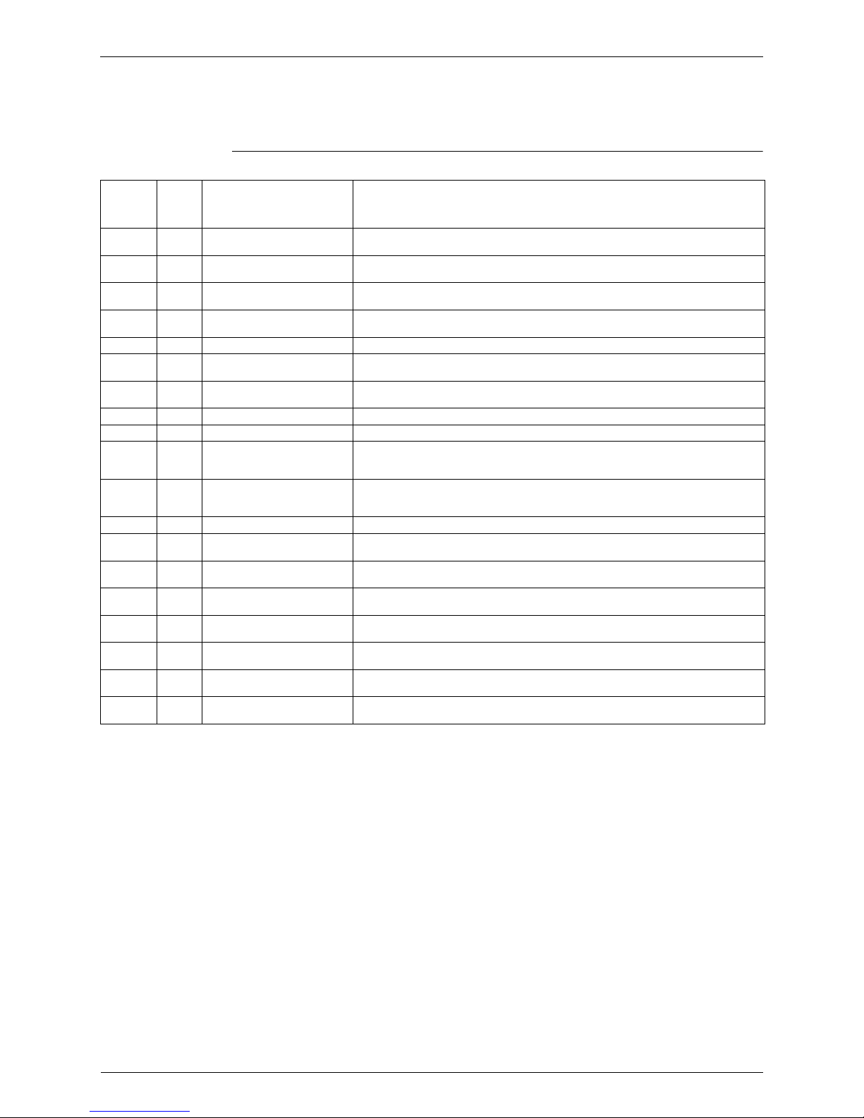
1.1.4 Using Icons
Icons are used to attract the attention of the reader to specific information. The meaning of each
icon is described in the table below:
1.1.5 Using Icons List
Caution
Check to see if the parts and wires are mounted and connected properly, and
if the connections at the soldered or crimped terminals are secure.
Improper installation and connections can cause excessive heat generation,
fire or an electrical shock.
If the installation platform or frame has corroded, replace it.
Corroded installation platform or frame can cause the unit to fall, resulting in
injury.
Check the grounding, and repair it if the equipment is not properly grounded.
Improper grounding can cause an electrical shock.
Be sure to measure the insulation resistance after the repair, and make sure
that the resistance is 1 Mohm or higher.
Faulty insulation can cause an electrical shock.
Be sure to check the drainage of the indoor unit after the repair.
Faulty drainage can cause the water to enter the room and wet the furniture
and floor.
Icon Type of
Information
Description
Note:
Note A “note” provides information that is not indispensable, but may
nevertheless be valuable to the reader, such as tips and tricks.
Caution
Caution A “caution” is used when there is danger that the reader, through
incorrect manipulation, may damage equipment, loose data, get
an unexpected result or has to restart (part of) a procedure.
Warning
Warning A “warning” is used when there is danger of personal injury.
Reference A “reference” guides the reader to other places in this binder or
in this manual, where he/she will find additional information on a
specific topic.

ESIE09-08 Introduction
ix
1.2 PREFACE
Thank you for your continued patronage of Daikin products.
This is the new service manual for Daikin's Year 2009 Daikin Altherma HT (high temperature)
air to water heat pump.
Daikin offers a wide range of models to respond to the residential heating market. We are
confident that customers will be able to find the models that best suit their needs.
This service manual contains information regarding the servicing of Daikin Altherma HT (R410A & R-134a) Heat Pump System.
August, 2009
After Sales Service Division

Introduction ESIE09-08
x

ESIE09-08
General Information 1
Part 1 - General Information
1. Model Names of Indoor/Outdoor Units & Tanks .....................................2
Model Names of Indoor/Outdoor Units & Tanks ESIE09-08
2 General Information
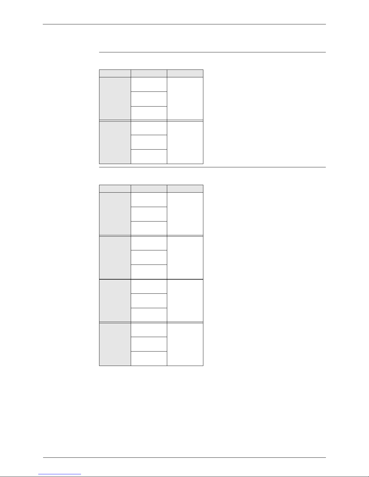
1. Model Names of Indoor/Outdoor Units & Tanks
Indoor Units
Outdoor Units
Type Model Name
Power Supply
EKHBRD
011 AA
V1014 AA
016 AA
EKHBRD
011 AA
Y1014 AA
016 AA
Type Model Name
Power Supply
ERRQ
011 AA
V1014 AA
016 AA
ERRQ
011 AA
Y1014 AA
016 AA
ERSQ
011 AA
V1014 AA
016 AA
ERSQ
011 AA
Y1014 AA
016 AA
ESIE09-08 Model Names of Indoor/Outdoor Units & Tanks
General Information 3
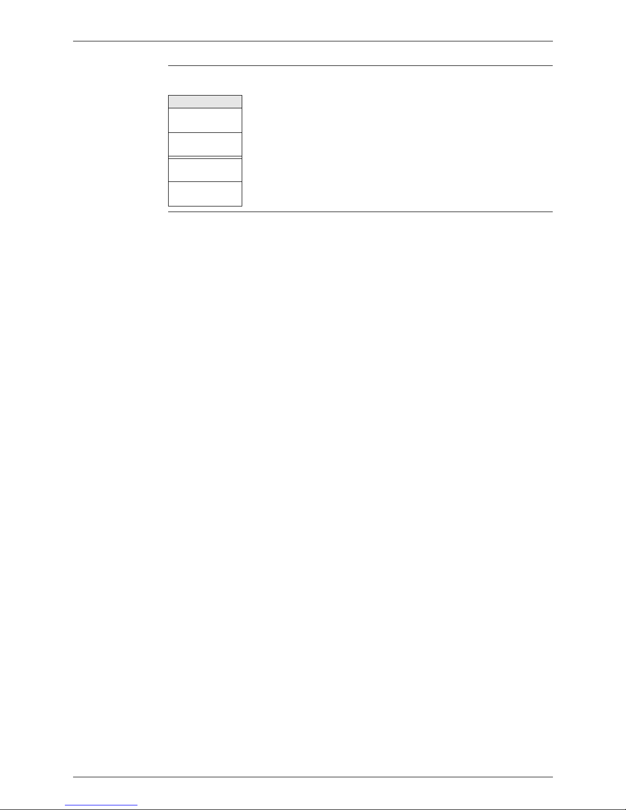
Tank
Model Name
EKHTS 200 A
EKHTS 260 A
EKHTSU 200 AA
EKHTSU 260 AA

Model Names of Indoor/Outdoor Units & Tanks ESIE09-08
4 General Information

ESIE09-08
Specifications 5
Part 2 - Specifications
1. Specifications ..........................................................................................6
1.1 Outdoor Units ...........................................................................................6
1.2 Indoor Unit................................................................................................8
Specifications ESIE09-08
6 Specifications
1. Specifications
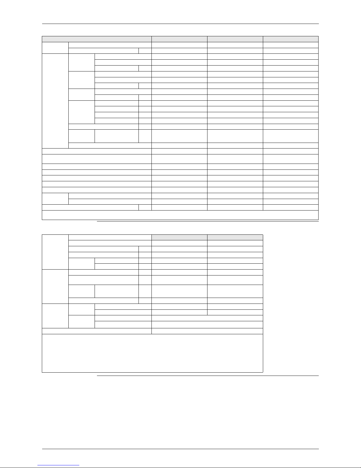
1.1 Outdoor Units
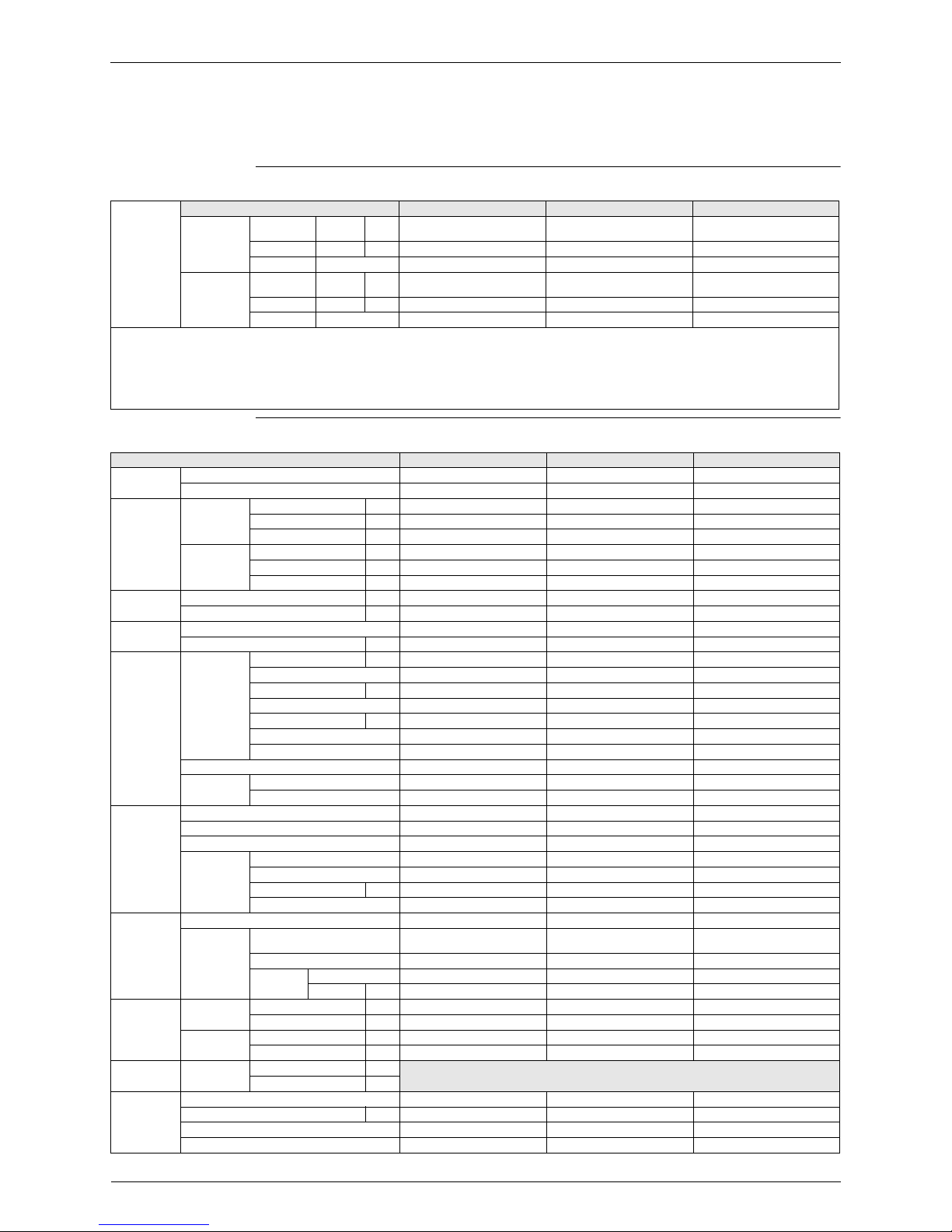
Capacity Information
Technical Specifications
For
combination
indoor units +
outdoor units
Indoor Units EKHBRD011AA(V1/Y1) EKHBRD014AA(V1/Y1) EKHBRD016AA(V1/Y1)
Condition 1 Heating
capacity
Nominal kW
11 14 16
Heating PI Nominal kW 3,57 4,66 5,57
COP Nominal 3,08 3,00 2,88
Condition 2 Heating
capacity
Nominal kW
11 14 16
Heating PI Nominal kW 4,40 5,65 6,65
COP Nominal 2,50 2,48 2,41
Notes
Condition 1
EW: 55°C, LW: 65°C, ΔT=10°C
Ambient conditions: 7°CDB/6°CWB
Condition 2
EW: 70°C, LW: 80°C, ΔT=10°C
Ambient conditions: 7°CDB/6°CWB
Outdoor units ER(S/R)Q011AA(V1/Y1) ER(S/R)Q014AA(V1/Y1) ER(S/R)Q016AA(V1/Y1)
Casing Colour Daikin White Daikin White Daikin White
Material Painted galvanised steel Painted galvanised steel Painted galvanised steel
Dimensions Unit Height mm 1345 1345 1345
Width mm 900 900 900
Depth mm 320 320 320
Packing Height mm 1524 1524 1524
Width mm 980 980 980
Depth mm 420 420 420
Weight Unit kg 120 120 120
Packed Unit kg 130 130 130
Packing Material Cardboard + Wood + EPS Cardboard + Wood + EPS Cardboard + Wood + EPS
Weight kg 8 8 8
Heat
Exchanger
Specifications Length mm 857 857 857
Nr of Rows 2 2 2
Fin Pitch mm 2 2 2
Nr of Passes 10 10 10
Face Area m² 1,131 1,131 1,131
Nr of Stages 60 60 60
Empty Tubeplate Hole 0 0 0
Tube type Hi-XSS Hi-XSS Hi-XSS
Fin Type Non-symmetric waffle louvre Non-symmetric waffle louvre Non-symmetric waffle louvre
Treatment Corrosion resistant Corrosion resistant Corrosion resistant
Fan Type Propellor Propellor Propellor
Quantity 2 2 2
Discharge direction Horizontal Horizontal Horizontal
Motor Quantity 2 2 2
Model Brushless DC motor Brushless DC motor Brushless DC motor
Output W 70 70 70
Drive Direct drive Direct drive Direct drive
Compressor Quantity 1 1 1
Motor Type Hermetically sealed scroll
compressor
Hermetically sealed scroll
compressor
Hermetically sealed scroll
compressor
Starting Method Direct on line Direct on line Direct on line
Crankcase
Heater
Quantity 1 1 1
Output W 33 33 33
Operation
Range
(1)
Heating Minimum ambient °C -20 -20 -20
Maximum ambient °C 20 20 20
Domestic hot
water
Minimum ambient °C -20 -20 -20
Maximum ambient °C 35 35 35
Sound Level
(nominal)
Heating Sound Power dBA
See technical data
Sound Pressure dBA
Refrigerant Type R-410A R-410A R-410A
Charge kg 4,5 4,5 4,5
Control Expansion valve (electronic) Expansion valve (electronic) Expansion valve (electronic)
Nr of Circuits 1 1 1
ESIE09-08 Specifications
Specifications 7
Electrical Specifications
Refrigerant Oil Type Daphne FVC68D Daphne FVC68D Daphne FVC68D
Charged Volume l 1,5 1,5 1,5
Piping
Connections
Liquid Quantity 1 1 1
Type Flare Flare Flare
Diameter (OD) mm 9,52 9,52 9,52
Gas Quantity 1 1 1
Type Flare Flare Flare
Diameter (OD) mm 15,9 15,9 15,9
Drain Quantity 3 3 3
Diameter (OD) mm 26 x 3 26 x 3 26 x 3
Piping Length Minimum m 3 3 3
Maximum m 50 50 50
Equivalent m 63 63 63
Chargeless m 10 10 10
Additional Refrigerant Charge kg/m see installation manual see installation manual see installation manual
Installation
height
difference
Maximum m
30 30 30
Heat Insulation Both liquid and gas pipes Both liquid and gas pipes Both liquid and gas pipes
Defrost Method Reversed cycle Reversed cycle Reversed cycle
Defrost Control Sensor for outdoor heat
exchanger temperature
Sensor for outdoor heat
exchanger temperature
Sensor for outdoor heat
exchanger temperature
Capacity Control Method Inverter controlled Inverter controlled Inverter controlled
Safety Devices (pressure) HPS HPS HPS
Safety Devices (fan) Fan motor thermal protector Fan motor thermal protector Fan motor thermal protector
Safety Devices (inverter) Inverter overload protector Inverter overload protector Inverter overload protector
Safety Devices (pcb) PC board fuse PC board fuse PC board fuse
Standard
Accessories
Item Installation manual Installation manual Installation manual
Quantity 1 1 1
Design pressure (high pressure side) bar 40 40 40
Notes
(1): for details see operation range TW drawing
Power Supply Name
ER(S/R)Q(011/014/016)AAV1 ER(S/R)Q(011/014/016)AAY1
Phase 1~ 3~
Frequency Hz 50 50
Voltage V 220-240 380-415
Voltage Range Minimum V 198 342
Maximum V 254 440
Current Z-max
(2)
Ω 0,28 -
Minimum Ssc
(3)
value kVa Equipment complying with EN/
IEC 61000-3-12
(1)
-
Maximum
running
Current
Heating A
27 13,5
Recommended fuses A 32 16
Wiring
Connections
For power
supply
Quantity 2G 4G
Wire type Note
(4)
Note
(4)
For connection
with indoor
unit
Quantity 2
Remark
F1+F2
Power Supply Intake Both indoor and outdoor unit
Notes
(1): European/International Technical Standard setting the limits for harmonic currents produced by equipment connected to public lowvoltage systems with input current > 16A and ≤ 75A per phase
(2): In accordance with EN/IEC 61000-3-11
(5)
, it may be necessary to consult the distribution network operator to ensure that the
equipment is connected only to a supply with Zsys
(6)
≤ Zmax
(3): Short-circuit power
(4): Select diameter and type according to national and local regulations
(5): European/International Technical Standard setting the limits for voltage changes, voltage fluctuations and flicker in public low-voltage
supply systems for equipment with rated current ≤ 75A
(6): System impedance
Outdoor units ER(S/R)Q011AA(V1/Y1) ER(S/R)Q014AA(V1/Y1) ER(S/R)Q016AA(V1/Y1)
Specifications ESIE09-08
8 Specifications
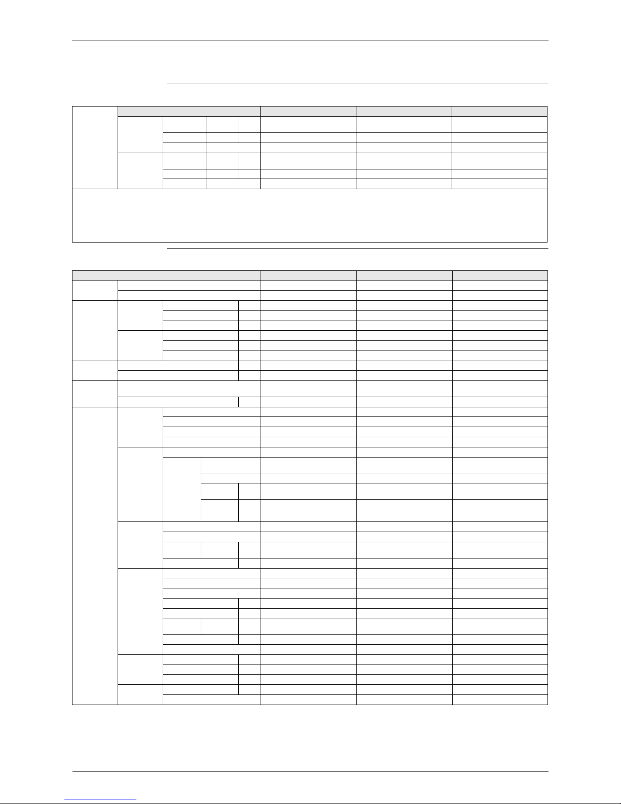
1.2 Indoor Unit
Capacity Information
Technical Specifications
For
combination
indoor units +
outdoor units
Indoor Units EKHBRD011AA(V1/Y1) EKHBRD014AA(V1/Y1) EKHBRD016AA(V1/Y1)
Condition 1 Heating
capacity
Nominal kW
11 14 16
Heating PI Nominal kW 3,57 4,66 5,57
COP Nominal 3,08 3,00 2,88
Condition 2 Heating
capacity
Nominal kW
11 14 16
Heating PI Nominal kW 4,40 5,65 6,65
COP Nominal 2,50 2,48 2,41
Notes
Condition 1
EW: 55°C, LW: 65°C, ΔT=10°C
Ambient conditions: 7°CDB/6°CWB
Condition 2
EW: 70°C, LW: 80°C, ΔT=10°C
Ambient conditions: 7°CDB/6°CWB
Indoor units EKHBRD011AA(V1/Y1) EKHBRD014AA(V1/Y1) EKHBRD016AA(V1/Y1)
Casing Colour Metallic Grey Metallic Grey Metallic Grey
Material pre coated sheetmetal pre coated sheetmetal pre coated sheetmetal
Dimensions Packing Height mm 860 860 860
Width mm 680 680 680
Depth mm 800 800 800
Unit Height mm 705 705 705
Width mm 600 600 600
Depth mm 695 695 695
Weight Machine weight kg 144,25 / 147,25 144,25 / 147,25 144,25 / 147,25
Gross weight kg 153 / 156 153 / 156 153 / 156
Packing Material EPS, Cardboard, MDF, Wood
(pallet), Metal
EPS, Cardboard, MDF, Wood
(pallet), Metal
EPS, Cardboard, MDF, Wood
(pallet), Metal
Weight kg 8,75 8,75 8,75
Main
components
Refrigerant
side heat
exchanger
Type Plate heat exchanger Plate heat exchanger Plate heat exchanger
Quantity 1 (60 plates) 1 (60 plates) 1 (60 plates)
Material AISI 316 AISI 316 AISI 316
Insulation material EPDM type EPDM type EPDM type
Cascade
compressor
Quantity 1 1 1
Motor Type Hermetically sealed scroll
compressor
Hermetically sealed scroll
compressor
Hermetically sealed scroll
compressor
Starting Method Direct online Direct online Direct online
Crankcase
Heater
Quantity
111
Crankcase
Heater
Output
W
33 33 33
Pump Type DC motor DC motor DC motor
Nr. of speed inverter controlled inverter controlled inverter controlled
Nominal
ESP unit
(1)
Heating kPa
94,0 91,9 89,7
Power input W 87 95 101
Water side
Heat
exchanger
Type Plate heat exchanger Plate heat exchanger Plate heat exchanger
Quantity 1 (50 plates) 1 (50 plates) 1 (50 plates)
Material AISI 316 AISI 316 AISI 316
Water volume l 2,78 2,78 2,78
Water flow rate Min. l/min N/A N/A N/A
Water flow
(1)
Heating l/min
15,8 20,1 22,9
Water flow rate Max.
(2)
l/min 31,6 40 45,8
Insulation material EPDM type EPDM type EPDM type
Expansion
vessel
Volume l 12 12 12
Max. water pressure bar 3 3 3
Pre pressure bar 1,5 1,5 1,5
Water filter Diameter perforations mm 1 1 1
Material Brass Brass Brass
ESIE09-08 Specifications
Specifications 9
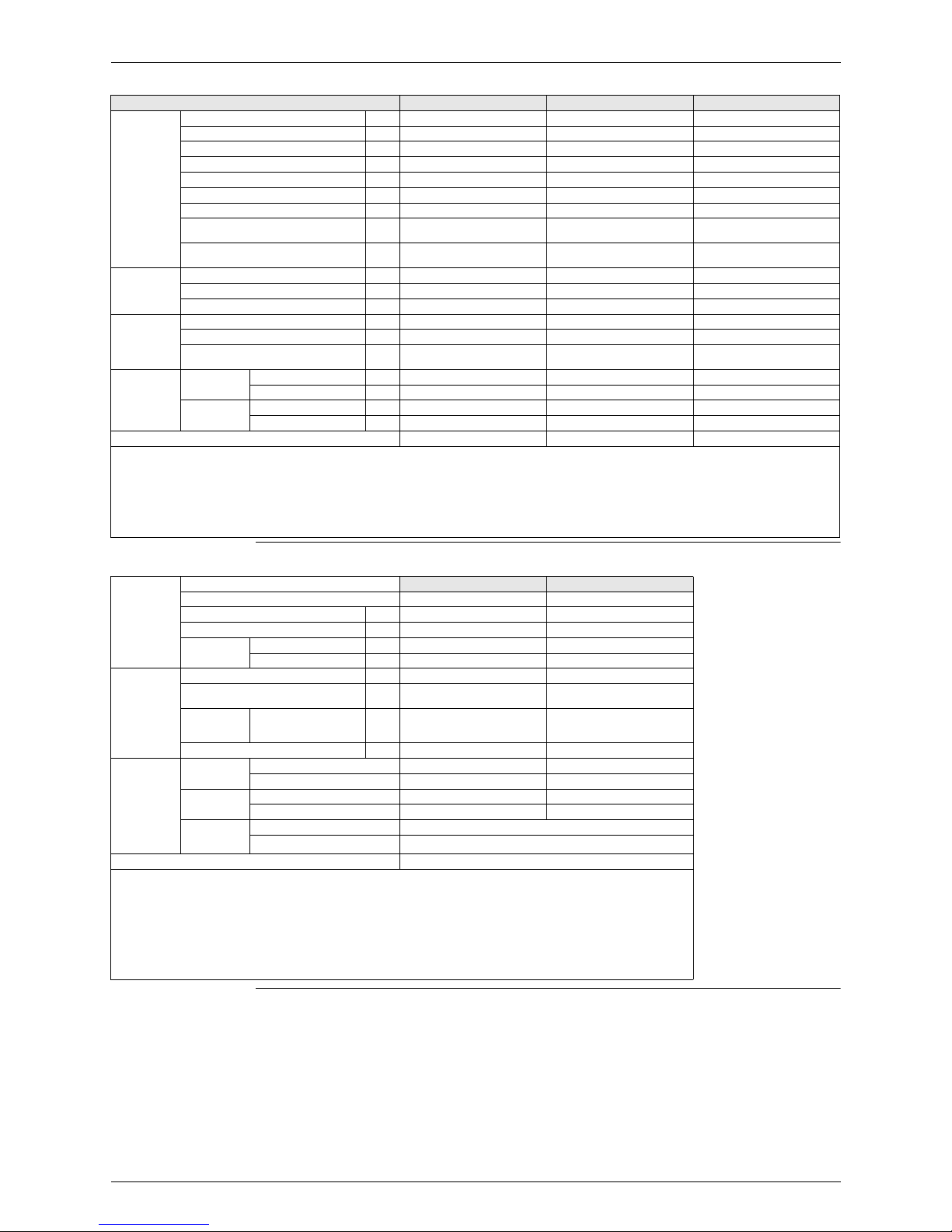
Electrical Specifications
Water circuit Piping connections diameter inch G 1”1/4 (female) G 1”1/4 (female) G 1”1/4 (female)
Piping inch 1” 1” 1”
Safety valve bar 3 3 3
Manometer Y/N Y Y Y
Drain valve / Fill valve Y/N Y Y Y
Shut off valve Y/N Y Y Y
Air purge valve Y/N Y Y Y
Heating water system minimum water
volume
l
20 20 20
Heating water system maximum water
volume
l
400 400 400
Refrigerant
Circuit
Gas side diameter mm 15,9 15,9 15,9
Liquid side diameter mm 9,52 9,52 9,52
Design pressure (high pressure side) bar 38 38 38
Sound Level
(3)
Sound Pressure at 55 - 65 °C [EW - LW]
(4)
dBA 43 45 46
Sound Pressure at 70 - 80 °C [EW - LW]
(4)
dBA 46 46 46
Sound Pressure low sound mode n° 1 at
55 - 65 °C [EW - LW]
(4)
dBA
40 43 45
Operation
range
(5)
Ambient Minimum °C -20 -20 -20
Maximum °C 20/(35)
(6)
20/(35)
(6)
20/(35)
(6)
Waterside
Minimum LW °C 25 25 25
Maximum LW °C 80 80 80
Installation place Indoor Indoor Indoor
Notes
(1): for ΔT = 10°C
(2): for ΔT = 5°C
(3): The data mentioned is valid in free field condition because it is measured in a semi-anechoic room. Measured value under actual installation conditions will be higher due
to environmental noise and sound reflections. These values are sound pressure levels measured at all sides (front / back / left / right / top) at 1m distance (see engineering
data book for more details). The values do not occur simultaneously on all mentioned sides
(4): EW = entering water temperature - LW = leaving water temperature
(5): for details see operation range TW drawing
(6): for DHW operation
Power Supply Name
EKHBRD(011/014/016)AAV1 EKHBRD(011/014/016)AAY1
Phase 1~ 3~
Frequency Hz 50 50
Voltage V 220-240 380-415
Voltage Range Minimum V 198 342
Maximum V 254 440
Current Z-max
(2)
Ω 0,35 -
Minimum Ssc
(3)
value kVa Equipment complying with EN/
IEC 61000-3-12
(1)
-
Maximum
running
Current
Heating A
21,7 12,5
Recommended fuses A 32 16
Wiring
Connections
For power
supply
Quantity 2G 4G
Wire type Note
(4)
Note
(4)
For power
supply
(5)
Quantity 2G + 2G 4G + 2G
Wire type Note
(4)
Note
(4)
For connection
with outdoor
unit
Quantity 2
Remark
F1+F2
Power Supply Intake Both indoor unit and outdoor unit
Notes
(1): European/International Technical Standard setting the limits for harmonic currents produced by equipment connected to public lowvoltage systems with input current > 16A and ≤ 75A per phase
(2): In accordance with EN/IEC 61000-3-11
(6)
, it may be necessary to consult the distribution network operator to ensure that the
equipment is connected only to a supply with Zsys
(7)
≤ Zmax
(3): Short-circuit power
(4): Select diameter and type according to national and local regulations
(5): In case of benefit kWh rate power supply installations
(6): European/International Technical Standard setting the limits for voltage changes, voltage fluctuations and flicker in public low-voltage
supply systems for equipment with rated current ≤ 75A
(7): System impedance
Indoor units EKHBRD011AA(V1/Y1) EKHBRD014AA(V1/Y1) EKHBRD016AA(V1/Y1)

Specifications ESIE09-08
10 Specifications

ESIE09-08
Refrigerant Circuit 11
Part 3 - Refrigerant Circuit
& Functional Parts
1. Refrigerant Circuit .................................................................................12
1.1 Outdoor Unit .................................................................................12
1.2 Indoor Unit ....................................................................................14
2. Functional Parts Layout ........................................................................16
2.1 ERRQ 011/014/016 AAV1, ERSQ 011/014/016 AAV1 ..........................16
2.2 ERRQ 011/014/016 AAY1, ERSQ 011/014/016 AAY1 ..........................18
2.3 EKHBRD 011/014/016 AAV1, EKHBRD 011/014/016 AAY1 .................20
2.4 EKHTS 200/260 A ..................................................................................22
2.5 EKHTSU 200/260 A ...............................................................................24
Refrigerant Circuit ESIE09-08
12 Refrigerant Circuit
1. Refrigerant Circuit
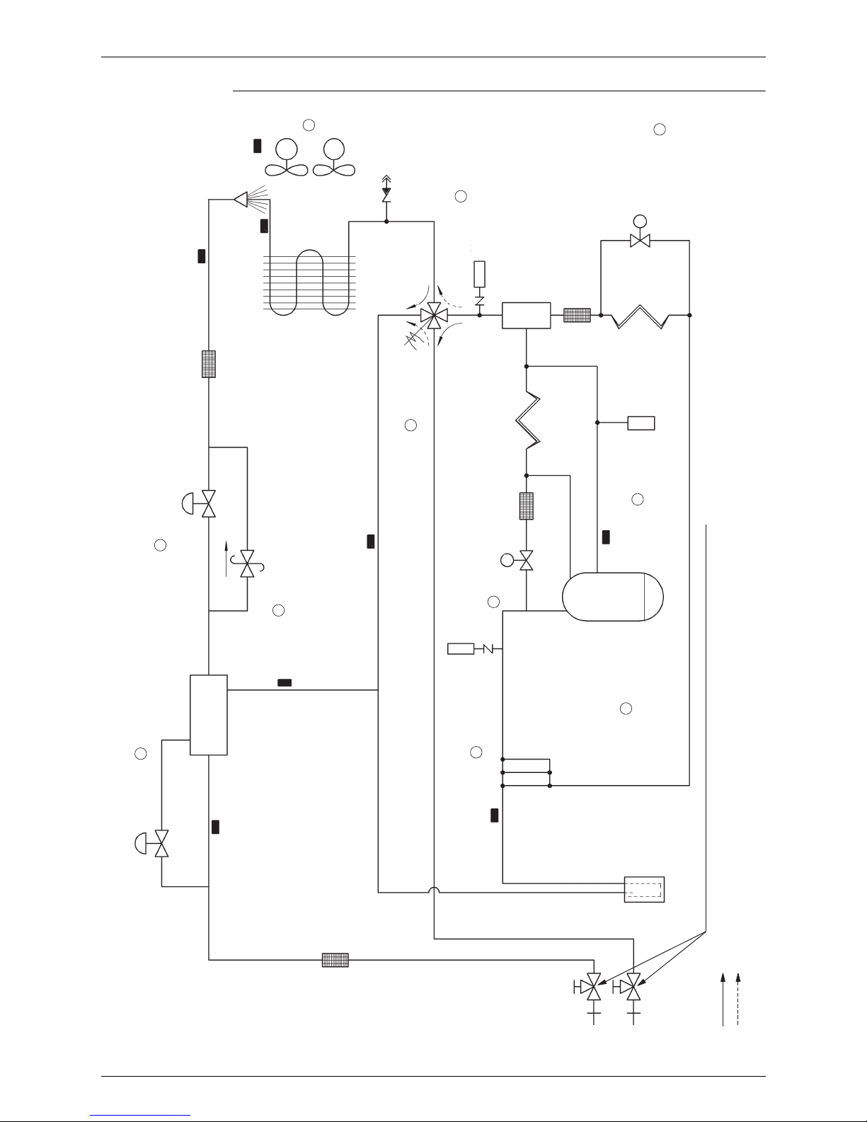
1.1 Outdoor Unit
ERRQ - ERSQ
No. in
refrigerant
system
diagram
Symbol Name Major Function
A M1C Inverter compressor (INV)
Inverter compressor is operated on frequencies between 36 Hz and 195 Hz by using
the inverter. In total there are 31 steps.
B
M1F
M2F
Inverter fan
Since the system is of air heat exchanging type, the fan is operated at 8 (9)-step
rotation speed by using the inverter.
CY1E
Electronic expansion valve
(Main: EV1)
While in heating operation, PI control is applied to keep the outlet superheated degree
of air heat exchanger constant.
DY3E
Electronic expansion valve
(Subcool: EV3)
Pl control is applied to keep the outlet superheated degree of subcooling heat
exchanger constant.
E Y2S Solenoid valve (Hot gas: SVP) Used to prevent the low pressure from transient falling.
FY3S
Solenoid valve (Unload circuit
SVUL)
Used to the unloading operation of compressor.
G Y1S Four way valve
Used to switch the operation mode between defrosting and heating. Activated during
heating (opposite concerning indoor unit).
H S1NPH High pressure sensor Used to detect high pressure.
I S1NPL Low pressure sensor Used to detect low pressure.
JS1PH
HP pressure switch (For INV
compressor)
In order to prevent the increase of high pressure when a malfunction occurs, this
switch is activated at high pressure of 4.0 MPa or more to stop the compressor
operation.
K—
Pressure regulating valve 1
(Receiver to discharge pipe)
This valve opens at a pressure of 4.0 MPa for prevention of pressure increase, thus
resulting in no damage of functional parts due to the increase of pressure in
transportation or storage.
1 R1T Thermistor (Outdoor air: Ta) Used to detect outdoor temperature, correct discharge pipe temperature, and others.
2R2T
Thermistor (INV discharge
pipe: Tdi)
used to detect discharge pipe temperature, make the temperature protection control of
compressor, and others.
3R3T
Thermistor
(Suction pipe1: Ts1)
used to detect suction pipe temperature, keep the suction superheated degree
constant in heating operation, and others.
4R4T
Thermistor (Heat exchanger
deicer: Tb)
Used to detect liquid pipe temperature of air heat exchanger, determine defrosting
operation, and others.
5R5T
Thermistor
(Suction pipe2: Ts2)
Used to the calculation of superheat and internal temperature of compressor etc.
6R6T
Thermistor (Subcooling heat
exchanger gas pipe: Tsh)
Used to control of subcooling electronic expansion valve.
7R7T
Thermistor
(Liquid pipe1: Tl1)
Liquid thermistor (internal control), and others.
8R8T
Thermistor
(Liquid pipe2: Tl2)
Liquid thermistor (internal control), and others.
ESIE09-08 Refrigerant Circuit
Refrigerant Circuit 13
ELECTRONIC
EXPANSION
VALVE (Y3E)
ELECTRONIC
EXPANSION
VALVE (Y1E)
HEAT
EXCHANGER
FILTER
FILTER
FILTER
FILTER
OIL SEPA-
RATOR
R8T
R1T
R4T
R2T
R5T
R3T
R6T
R7T
ACCUMULATOR
HEATING
STOP VALVE (WITH SERVICE PORT ON FIELD PIPING SIDE
ø 7.9MM FLARE CONNECTION)
DEFROST
FANS
M1F
M2F
SP
p >
SERVICE PORT
4-WAY VALVE
(Y1S)
CAPILLARY
TUBE
CAPILLARY
TUBE
HIGH PRESSURE
SENSOR (S1NPH)
HIGH
PRESSURE
SWITCH
(S1PH)
SOLENOID VALVE
(Y2S)
SOLENOID VALVE
(Y3S)
DOUBLE PIPE
HEAT EXCHANGER
PRESSURE REGULATING
VALV E
SV
SV
SP
COMPRESSOR
(M1C)
Low pressure
sensor (S1NPL)
A
B
C
D
K
G
H
I
F
J
E
Refrigerant Circuit ESIE09-08
14 Refrigerant Circuit
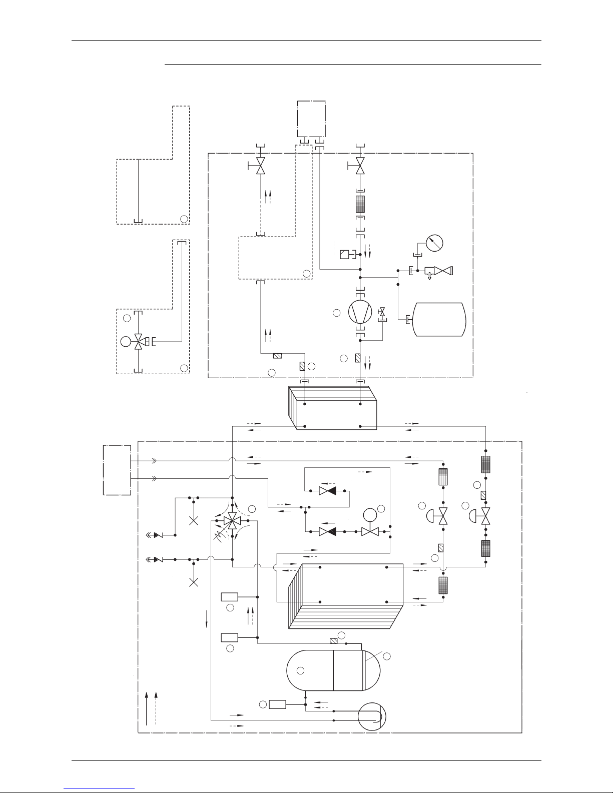
1.2 Indoor Unit
EKHBRD 011/014/016 AA(V1/Y1)
No. in
refrigerant
system
diagram
Symbol Name Major Function
AM1C
Inverter compressor on
R-134a
Inverter compressor is operated on frequencies between 40 Hz and 210 Hz by using
the inverter. Max. of 30 steps.
B Y1R Four way valve
Used to switch the operation mode between heating and defrost. Not activated during
heating (opposite concerning outdoor unit).
C B1PL Low pressure sensor Used to detect low pressure.
D B1PH High pressure sensor Used to detect high pressure.
E S1PH High pressure switch
In order to prevent the increase of high pressure when a malfunction occurs, this
switch is activated at high pressure of 3.8 MPa or more to stop the compressor
operation.
F K2S 2-way valve Used during defrost operation.
G K1E Electronic expansion valve Used to regulate the refrigerant flow of R-410A.
H K2E Electronic expansion valve Used to regulate the refrigerant flow of R-134a.
I E1HC Crankcase heater
Used to prevent migration (when the unit is OFF) and condensation of refrigerant in
the crankcase of compressor.
J M1P DC inverter pump Used to regulate water flow to achieve a constant ΔT.
KQ2L
Thermistor protector water
piping
Used to protect the water system against high temperatures.
LK1S
3 way valve (option for water
tank)
Used to switch over between space heating and domestic hot water.
1 R3T Liquid thermistor R-410A Subcool calculation.
2 R6T Discharge thermistor
Used to detect discharge pipe temperature, make the temperature protection control of
compressor, and others.
3 R7T Liquid thermistor R-134a Subcool calculation.
4 R4T Returning water thermistor Used to control and protect the water system.
5 R5T Leaving water thermistor Used to control and protect the water system.
ESIE09-08 Refrigerant Circuit
Refrigerant Circuit 15
FILTER FILTER
FILTER FILTER
FILTER
DRAIN VALVE
BLOW
OFF
SAFETY
VALV E
PRESSURE
GAUGE
EXPANSION
VESSEL
WATER INLET
OPTION DOMESTIC HOT
WATER TANK
PLATE
HEAT
EX-
CHANGER
R-134a
PLATE HEAT
EXCHANGER
R-410A /
R-134a
CHECK
VALV E
M1C
E1HC
R6T
Y1R
M
K1S
R5T
Q2L
R4T
M1P
K2S
K1E
K2E
R3T
R7T
B1PL
B1PH
S1PH
ACCUMULATOR
CHECK
VALV E
*KHTS*
200~270*
G 1”1/4 (female)
WATER OUTLET
STANDARD
WATER SIDE
3-WAY
VALV E
REFRIGERANT SIDE
OUTDOOR UNIT
SERVICE PORT
5/16”
SERVICE PORT
5/16”
*R*Q011~016**
FIELD INSTALLATION
(DELIVERED WITH
OPTION DOMESTIC
HOT WATER TANK)
G 1”1/4 (female)
AIR
PURGE
SHUT OFF
VALV E
SHUT OFF
VALV E
FIELD PIPING ø15.9 C 1220T-0
FIELD PIPING ø9.5 C 1220T-0
SV
HEATING
DEFROST
G
H
F
E
B
L
1
1
K
4
5
J
1
D
C
I
1
3
A
2
Functional Parts Layout ESIE09-08
16 Refrigerant Circuit
2. Functional Parts Layout
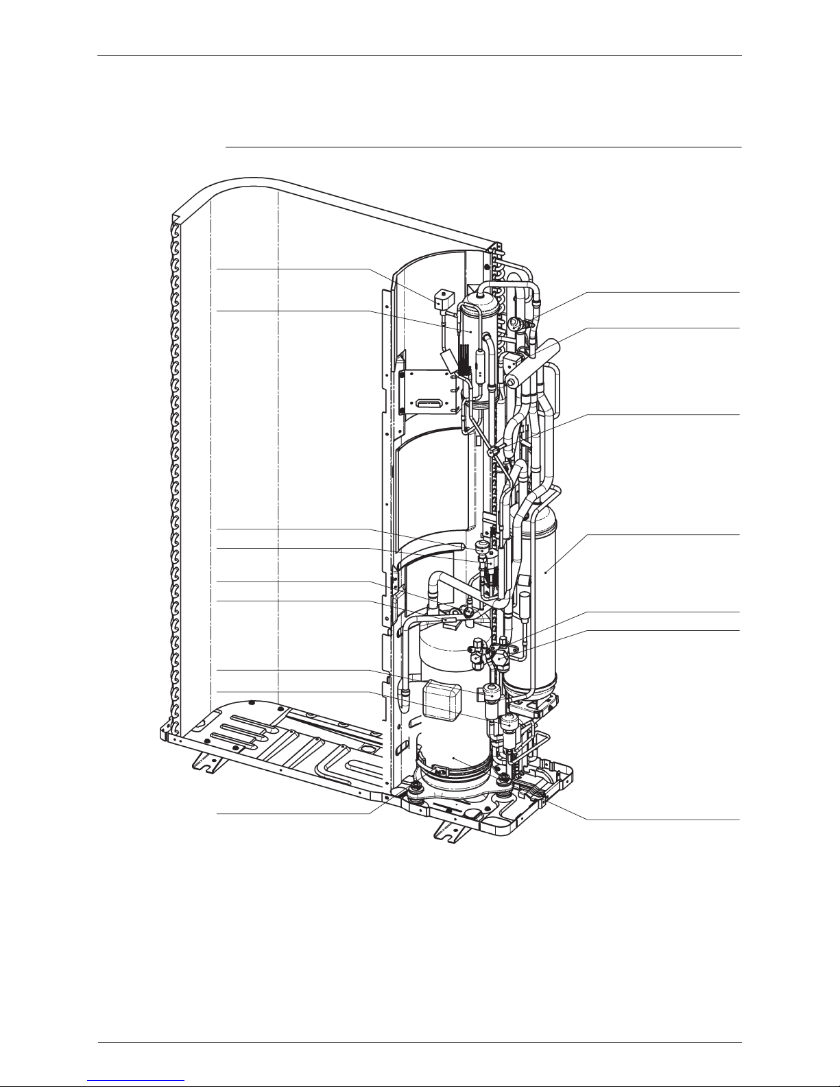
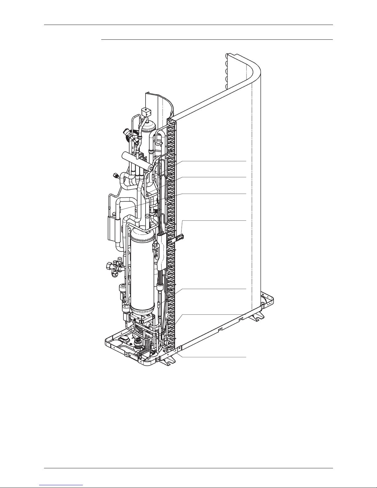
2.1 ERRQ 011/014/016 AAV1, ERSQ 011/014/016 AAV1
Bird’s-eye view
Remark:
Bottom plate heater:
Standard for ERRQ
Optional for ERSQ
Y2S
S1NPL
Solenoid valve
S1NPH
High pressure sensor
Y1S
4-way valve
Service port
Accumulator
Service port liquid
Service port gas
Compressor
Oil separator
Low pressure sensor
R2T
Discharge thermistor
Y1E
Electric expansion valve
Y3E
Electric expansion valve
E1HC
Crankcase heater
S1HP
High pressure switch
Y3S
Solenoid valve
ESIE09-08 Functional Parts Layout
Refrigerant Circuit 17
Back view
R6T
Subcool thermistor
R3T
Suction 1 thermistor
R8T
Liquid pipe 2 thermistor
R4T
Coil thermistor
R7T
Liquid pipe 1 thermistor
R1T
Ambient thermistor
R5T
Suction 2 thermistor
Functional Parts Layout ESIE09-08
18 Refrigerant Circuit
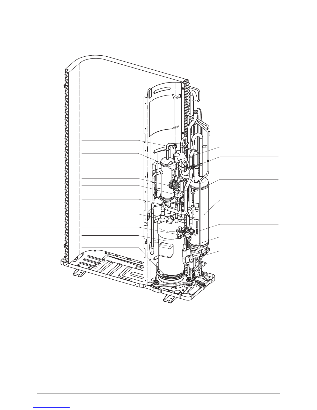
2.2 ERRQ 011/014/016 AAY1, ERSQ 011/014/016 AAY1
Bird’s-eye view
Remark:
Bottom plate heater:
Standard for ERRQ
Optional for ERSQ
Y2S
S1NPH
Solenoid valve
Y3S
Solenoid valve
S1NPL
Low pressure sensor
Y1S
4-way valve
Y1E
Electronic expansion valve
Y3E
Electronic expansion valve
Service port
Accumulator
Service port gas
Oil separator
Service port liquid
Compressor
High pressure sensor
S1PH
High pressure switch
R2T
Discharge thermistor
E1HC Crankcase heater
 Loading...