

Daikin A1 BO Installation manuals
For certified companies
ROTEX
A1 BO
Installation and maintenance
instructions
Oil condensing boiler
0035 BM 105.3
Types
A1 BO 15-e
A1 BO 20-e
A1 BO 27-e
A1 BO 34-e
GB
Output 02/2014

List of contents
1 Guarantee and conformity . . . . . . . . . . . . . 3
1.1 Warranty conditions . . . . . . . . . . . . . . . . . . . . . . . .3
1.2 Declaration of conformity . . . . . . . . . . . . . . . . . . . .3
2 Safety . . . . . . . . . . . . . . . . . . . . . . . . . . . . . . 4
2.1 Observing instructions . . . . . . . . . . . . . . . . . . . . . .4
2.2 Warning signs and explanation of symbols. . . . . . .4
2.3 Avoid danger. . . . . . . . . . . . . . . . . . . . . . . . . . . . . .4
2.4 Proper use . . . . . . . . . . . . . . . . . . . . . . . . . . . . . . .4
2.5 Instructions for operating safety . . . . . . . . . . . . . . . 5
2.5.1 Before working on the heating system . . . . . . . . . . . .5
2.5.2 Electrical installation . . . . . . . . . . . . . . . . . . . . . . . . . . 5
2.5.3 Installation room . . . . . . . . . . . . . . . . . . . . . . . . . . . . . 5
2.5.4 Requirements for the heating water . . . . . . . . . . . . . . 5
2.5.5 Heating system and sanitary connection. . . . . . . . . . . 5
2.5.6 Fuel . . . . . . . . . . . . . . . . . . . . . . . . . . . . . . . . . . . . . . . 5
2.5.7 Operation. . . . . . . . . . . . . . . . . . . . . . . . . . . . . . . . . . .5
2.5.8 Instructing the user/owner . . . . . . . . . . . . . . . . . . . . . . 5
3 Product description. . . . . . . . . . . . . . . . . . . 6
3.1 Boiler design and components . . . . . . . . . . . . . . . .6
3.2 Brief description . . . . . . . . . . . . . . . . . . . . . . . . . . .7
4 Set-up and installation . . . . . . . . . . . . . . . . 8
4.1 Dimensions and connection dimensions. . . . . . . . .8
4.2 Different set-ups . . . . . . . . . . . . . . . . . . . . . . . . . .10
4.2.1 Operation independent of ambient air. . . . . . . . . . . .11
4.2.2 Operation partially independent of ambient air . . . . . 11
4.2.3 Ambient air dependent operation . . . . . . . . . . . . . . .12
4.3 Transport and delivery . . . . . . . . . . . . . . . . . . . . .12
4.4 Installing the Oil condensing boiler . . . . . . . . . . . .13
4.4.1 Selecting the installation site . . . . . . . . . . . . . . . . . . 13
4.4.2 Setting up the unit . . . . . . . . . . . . . . . . . . . . . . . . . . . 14
4.5 Air/flue system (LAS) . . . . . . . . . . . . . . . . . . . . . .14
4.5.1 General instructions for flue system . . . . . . . . . . . . . 14
4.5.2 Connecting the flue gas line to the ROTEX A1 BO. .15
4.5.3 Flue gas system kits . . . . . . . . . . . . . . . . . . . . . . . . . 16
4.6 Water connection . . . . . . . . . . . . . . . . . . . . . . . . .17
4.7 Connect the condensate drain . . . . . . . . . . . . . . .18
4.8 Establish connection and electrical equipment. . .18
4.8.1 Instructions concerning electrical connection . . . . . .18
4.8.2 Establishing the electrical connection . . . . . . . . . . . . 18
4.8.3 Connecting the temperature sensor . . . . . . . . . . . . .19
4.8.4 Connect the additional electrical components. . . . . .20
4.9 Connecting and filling up the oil line . . . . . . . . . . .20
4.10 Filling the heating system . . . . . . . . . . . . . . . . . .20
5 Start-up. . . . . . . . . . . . . . . . . . . . . . . . . . . . 21
5.1 Initial start-up . . . . . . . . . . . . . . . . . . . . . . . . . . . .21
5.2 Checklists for start-up . . . . . . . . . . . . . . . . . . . . . .22
6 Control unit . . . . . . . . . . . . . . . . . . . . . . . . 23
6.1 Operating elements on the boiler control panel . .23
6.2 Replacing the operating section RoCon B1 . . . . .24
6.3 Changing the boiler control panel . . . . . . . . . . . . .24
6.4 Changing cables . . . . . . . . . . . . . . . . . . . . . . . . . .25
6.5 Changing the sensors. . . . . . . . . . . . . . . . . . . . . .26
6.5.1 Changing flow / return flow temperature sensor . . . . 26
6.5.2 Changing the flue gas temperature sensor . . . . . . . . 27
6.5.3 Changing the storage tank temperature sensor . . . .27
6.6 Replacing the fuse or control panel circuit board .28
6.7 Wiring diagram . . . . . . . . . . . . . . . . . . . . . . . . . . . 28
7.3 Burner setting . . . . . . . . . . . . . . . . . . . . . . . . . . . .31
7.3.1 Settings . . . . . . . . . . . . . . . . . . . . . . . . . . . . . . . . . . .31
7.3.2 Instructions for burner setting . . . . . . . . . . . . . . . . . . 32
7.3.3 Check vacuum in the oil pump and set the oil
pump pressure. . . . . . . . . . . . . . . . . . . . . . . . . . . . . .33
7.3.4 Set air quantity. . . . . . . . . . . . . . . . . . . . . . . . . . . . . .33
7.3.5 Recirculation gap. . . . . . . . . . . . . . . . . . . . . . . . . . . .34
7.3.6 Check and set electrode distance and the
distance between oil nozzles and air nozzles . . . . . . 34
7.4 Removing/fitting the burner. . . . . . . . . . . . . . . . . . 35
7.4.1 Move the burner to service position. . . . . . . . . . . . . . 35
7.4.2 Removing/fitting the flame tube. . . . . . . . . . . . . . . . . 36
7.4.3 Removing/fitting the burner . . . . . . . . . . . . . . . . . . . . 36
7.5 Removing/fitting the air nozzle . . . . . . . . . . . . . . . 36
7.6 Automatic firing connections. . . . . . . . . . . . . . . . .37
7.7 Ignition transformer with flame monitor. . . . . . . . . 37
7.8 Oil burner pump and oil filter. . . . . . . . . . . . . . . . . 37
8 Hydraulic connection . . . . . . . . . . . . . . . . .38
8.1 Connection accessories . . . . . . . . . . . . . . . . . . . . 38
8.1.1 Safety group SBG A1 . . . . . . . . . . . . . . . . . . . . . . . . 38
8.1.2 Connection kit A1 . . . . . . . . . . . . . . . . . . . . . . . . . . . 38
8.2 Hydraulic system connection . . . . . . . . . . . . . . . . 40
9 Service and maintenance . . . . . . . . . . . . . .41
9.1 General overview of service and maintenance. . .41
9.2 Service and maintenance tasks . . . . . . . . . . . . . .41
9.2.1 Removing panelling (and cleaning it) . . . . . . . . . . . . 41
9.2.2 Checking the connections and pipes. . . . . . . . . . . . .42
9.2.3 Checking and cleaning the condensate drain.. . . . . .42
9.2.4 Checking the flue gas temperature . . . . . . . . . . . . . .44
9.2.5 Checking and cleaning the combustion chamber . . .45
9.2.6 Checking the oil filter and cleaning the oil pump
filter . . . . . . . . . . . . . . . . . . . . . . . . . . . . . . . . . . . . . .46
9.2.7 Checking the burner . . . . . . . . . . . . . . . . . . . . . . . . . 46
9.2.8 Replacing the oil nozzle and ignition electrodes . . . . 47
10 Faults and malfunctions . . . . . . . . . . . . . . .48
10.1 Troubleshooting . . . . . . . . . . . . . . . . . . . . . . . . . .48
10.2 Overview of possible malfunctions . . . . . . . . . . . .48
10.3 Fault codes . . . . . . . . . . . . . . . . . . . . . . . . . . . . . .50
10.4 Rectifying burner faults and STB faults . . . . . . . .51
10.5 Emergency operation . . . . . . . . . . . . . . . . . . . . . . 51
11 Taking out of service. . . . . . . . . . . . . . . . . .52
11.1 Temporary shutdown . . . . . . . . . . . . . . . . . . . . . .52
11.2 Final shutdown and disposal . . . . . . . . . . . . . . . .52
12 Technical data . . . . . . . . . . . . . . . . . . . . . . .53
12.1 Basic Data Oil Boiler. . . . . . . . . . . . . . . . . . . . . . .53
12.2 Heating circulation pump and 3-way diverter
valve (A1 BO - all types) . . . . . . . . . . . . . . . . . . . .55
12.3 Flow rate and residual feed height . . . . . . . . . . . . 55
12.4 Temperature sensor . . . . . . . . . . . . . . . . . . . . . . .56
13 Notes. . . . . . . . . . . . . . . . . . . . . . . . . . . . . . .57
14 List of keywords . . . . . . . . . . . . . . . . . . . . .59
15 For the chimney sweep . . . . . . . . . . . . . . .60
15.1 Data for designing the flue gas pipe . . . . . . . . . . .60
15.2 Emissions measurement . . . . . . . . . . . . . . . . . . .60
7 Oil burner . . . . . . . . . . . . . . . . . . . . . . . . . . 30
7.1 Design and brief description . . . . . . . . . . . . . . . . .30
7.2 Safety function . . . . . . . . . . . . . . . . . . . . . . . . . . .31
2
FA ROTEX A1 BOe - 02/2014
1 x Guarantee and conformity
1 Guarantee and conformity
1.1 Warranty conditions
The legal guarantee conditions fundamentally apply. Our warranty conditions beyond that can be found online on your sales
representative's webpage.
1.2 Declaration of conformity
For the central condensing heating units in the boiler range ROTEX A1 BO
We, ROTEX Heating Systems GmbH, declare under our sole responsibility that the products
Product Order No. Product Order No.
ROTEX A1 BO 15-e 15 49 60 ROTEX A1 BO 27-e 15 49 62
ROTEX A1 BO 20-e 15 49 61 ROTEX A1 BO 34-e 15 49 63
with the product ID No.: CE 0035 BM-105.3 comply, in its standard design, with the following European Directives:
2004/108/EC Electromagnetic Compatibility Directive
2006/42/EC EC Machinery Directive
2006/95/EC EC Low Voltage Directive
92/42/EEC Boiler efficiency requirements directive
Person responsible for the generation of the technical documents: Dipl.-Ing. W. Scholer
Güglingen, 18.03.2013 Dr.-Ing. Franz Grammling
Managing Director
FA ROTEX A1 BOe - 02/2014
3
2 x Safety
2 Safety
2.1 Observing instructions
This instruction is the >> Original Version << in your language.
Please read this manual carefully and thoroughly before proceeding with the installation or modification of the heating
system.
These instructions are intended for authorised and trained
heating and sanitation experts who have experience in the proper
installation and maintenance of heating systems and hot water
storage tanks by virtue of their technical training and knowledge.
This manual provides all the necessary information for installation, start-up and maintenance, as well as basic information on
operation and settings. Please go through the attached documents for a detailed description of operation and control.
All heating parameters needed for smooth operation are already
factory-set. Please refer to other relevant documents for information on setting the control.
Relevant documents
– ROTEX A1 BO:
– For the operator
– Operating manual for the operator.
– ROTEX RoCon BF Controller": Control System Instructions
The documents are included in the scope of supply.
2.2 Warning signs and explanation of symbols
Meaning of the warnings
Warnings in this manual are classified according into their severity and probability of occurrence.
DANGER!
Draws attention to imminent danger.
Disregarding this warning can lead to serious injury or
death.
WARNING!
Indicates a potentially dangerous situation.
Disregarding this warning can result in serious injury
or death.
CAUTION!
Indicates a situation which may cause possible
damage.
Disregarding this warning can lead to damage to
property and the environment.
Special warning signs
Some types of danger are represented by special symbols:
Electric power
Risk of burning or scalding.
Risk of poisoning
Danger of chemical burns
Order number
Notes related to Order numbers are identified by the cart
symbol .
Handling instructions
Ɣ Instructions on actions are shown as a list. Actions of which
the sequential order must be maintained are numbered.
Î Results of actions are identified with an arrow.
2.3 Avoid danger
ROTEX Oil condensing boiler conforms to the state-of-the-art
and meets all recognised technical requirements. However,
improper use may result in serious physical injuries or death, as
well as property damage. Install and operate only ROTEX Oil
condensing boiler to avoid danger:
– as stipulated and in perfect condition,
– with an awareness of the safety and hazards involved.
This assumes knowledge and use of the contents of this manual,
the relevant accident prevention regulations and the recognised
safety-related and occupational medical rules.
2.4 Proper use
The ROTEX A1 BO may only be used for the heating of hot water
heating systems. It must be installed, connected and operated
only according to the information in this manual.
The ROTEX A1 BO may only be operated with the integrated circulation pump and only in combination with a controller approved
by ROTEX.
Any other use outside the intended use is considered as improper. The operator alone shall bear responsibility for any resulting damage.
Use as intended also involves compliance with maintenance and
inspection conditions. Spare parts must at least satisfy the technical requirements defined by the manufacturer. This is the case,
for example, with original spare parts.
This symbol identifies user tips and particularly useful
information, but not warnings or hazards.
4
FA ROTEX A1 BOe - 02/2014

2 x Safety
2.5 Instructions for operating safety
2.5.1 Before working on the heating system
Ɣ Work on the heating system (such as installation, connection
and initial start-up) may only be carried out by authorised,
trained heating technicians.
Ɣ Switch off the main switch and secure it against unintended
switching on when carrying out any work on the heating
system.
Ɣ Seals must not be damaged or removed.
Ɣ Make sure that the safety valves comply with the require-
ments of EN 12828 when connecting on the heating side, and
with the requirements of EN 12897 when connecting on the
domestic water side.
2.5.2 Electrical installation
Ɣ Electrical installations must only be conducted by electrical
engineers and in compliance with valid electrical guidelines
as well as the specifications of the energy supply company.
Ɣ Before completing the mains connection, compare the mains
voltage, indicated on the type plate (230 V, 50 Hz) with the
supply voltage.
Ɣ Before beginning work on live parts, disconnect them from the
power supply (switch off main switch, remove fuse) and
secure against unintentional restart.
Ɣ Equipment covers and service panels must be replaced as
soon as the work is completed.
2.5.5 Heating system and sanitary connection
Ɣ Create a heating system according to the safety requirements
of EN 12828.
Ɣ With sanitary connection, you must observe;
– EN 1717 - Protection of domestic water from contamina-
tion in domestic water installations and general requirements concerning safety equipment for the prevention of
domestic water contamination by back-flow
– EN 806 - Technical regulations for domestic water instal-
lations (TRWI)
– and, in addition, the country-specific legal regulations.
During operation of the ROTEX A1 BO, the storage tank temperature may exceed 60 °C, particularly when solar power is used.
Ɣ Therefore, incorporate scald protection during the installation
of the system (domestic hot water mixing construcion, e.g.
VTA32, 15 60 16).
2.5.6 Fuel
Ɣ Use only the approved heating oils as fuel (see chapter 12
"Technical data").
2.5.7 Operation
Ɣ Operate ROTEX A1 BO only with closed silencer hoods.
Ɣ Only operate the ROTEX A1 BO if all the prerequisites as per
the checklist in chapter 5.2 are fulfilled.
2.5.3 Installation room
Ɣ Operate ROTEX A1 BO only if sufficient combustion air
supply is ensured. If you operate the ROTEX A1 BO in a
room-air independent manner with a concentric air/flue gas
system (LAS) dimensioned as per ROTEX standard, this is
fulfilled automatically and there are no other conditions for the
equipment erection room. With installation in residential
rooms, this method of operation applies exclusively.
Ɣ Make sure that, with installation in a room-air dependent or
limited room-air independent manner, an inlet air opening to
the outside of at least 150 cm
Ɣ Do not operate the ROTEX A1 BO by the ambient air
dependent method in rooms with aggressive vapours (e.g.
hair spray, perchloroethylene, carbon tetrachloride), strong
dust formation (e.g. workshop) or high humidity (e.g. laundry).
Ɣ Strictly keep the minimum distances to walls and other
objects (see chapter 4.1).
2
is provided.
2.5.4 Requirements for the heating water
Avoid damage caused by deposits and corrosion: Observe
the relevant regulations of technology to prevent creation of corrosion products and deposits.
Measures for desalination, softening or hardness stabilization are
necessary, if the filling and top-up water have a high total
hardness (>3 mmol/l - sum of the calcium and magnesium concentrations, calculated as calcium carbonate.
Using filling water and top-up water which does not meet the
stated quality requirements can cause a considerably reduced
service life of the equipment. The responsibility for this is entirely
that of the operator.
2.5.8 Instructing the user/owner
Ɣ Before you hand over the heating system, explain to the
owner how he/she can operate and check the heating
system.
Ɣ Hand over the technical documentation (at least the operating
instruction manual and operating handbook) to the user and
advise him that these documents must be made available at
all times and be stored in the immediate vicinity of the unit.
Ɣ Make a record of the handover by filling out and signing the
installation and instruction forms jointly with the user/owner.
FA ROTEX A1 BOe - 02/2014
5
3 x Product description
3 Product description
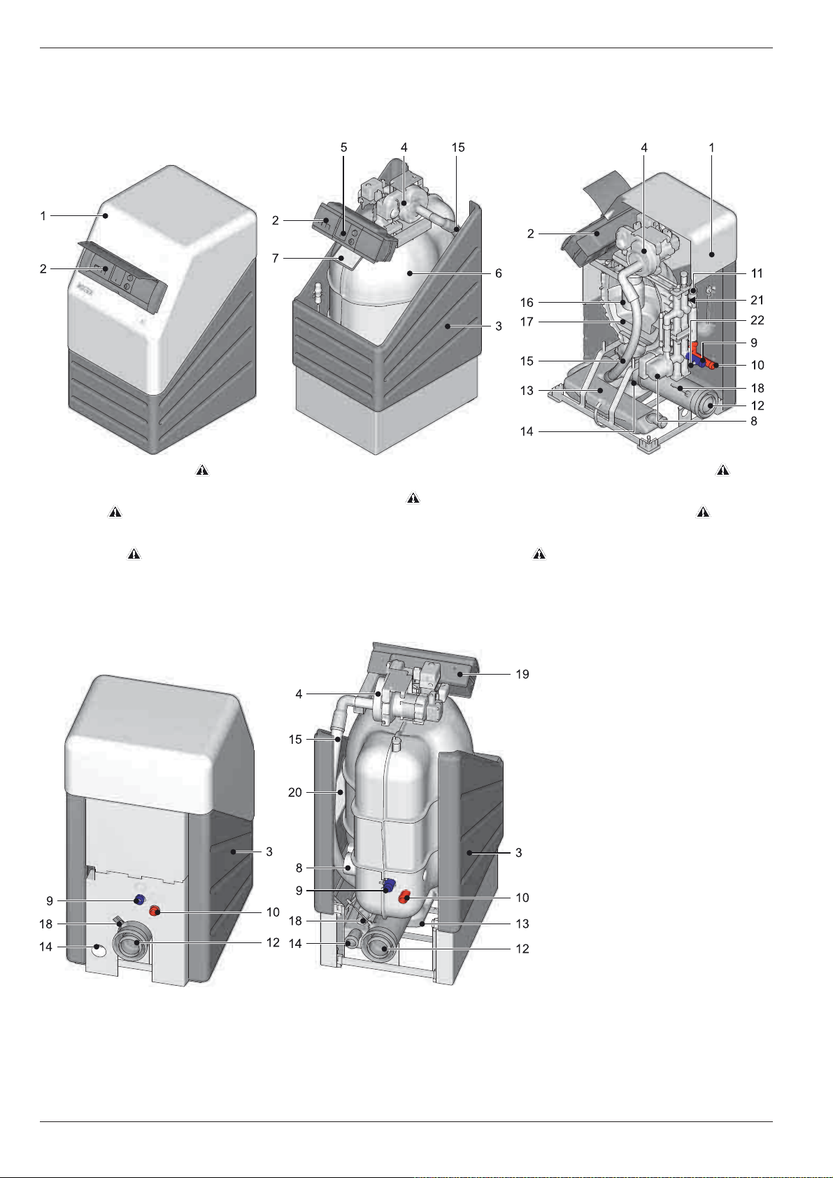
3.1 Boiler design and components
A1 BO 15-e / A1 BO 20-e A1 BO 27-e / A1 BO 34-e A1 BO Schematic
1 Sound insulation hood
2 Boiler control panel
3 Boiler cladding
4 Burner
5 Control system
6 Boiler main body with heat and sound
insulation
7 Type plate with serial number
8 Heating circulation pump
Fig. 3-1 Constituent parts of the A1 BO - view from the front + schematic
9 Heating return flow (cold)
10 Heating flow (hot)
11 Pressure sensor
12 Flue gas/supply air connection
13 Condensate treatment unit
14 Condensate drain
15 Air supply hose
16 Flame tube
17 Combustion chamber insert
A1 BO 15-e / A1 BO 20-e A1 BO 27-e / A1 BO 34-e
18 Flue gas temperature sensor
19 Circuit board (electrical connections)
20 Document pouch
21 Flow temperature sensor
22 Return flow temperature sensor
Safety devices
Fig. 3-2 Constituents of the A1 BO - view from the rear
for legend see fig. 3-1
6
FA ROTEX A1 BOe - 02/2014

3.2 Brief description
3 x Product description
The ROTEX Oil condensing boiler in the A1 BO series is a fully
preassembled oil condenser unit.
Operating instructions
The ROTEX Oil condensing boiler A1 BO is designed to be
operated independently of the room air (concentric flue gas/air
inlet piping). The burner suctions the combustion air directly in
through an installation shaft or a double-walled flue gas pipe. This
operating mode has several advantages:
– The heating room does not need any ventilation opening into
the open air and therefore does not cool down.
– Lower energy consumption.
– Additional energy recovery in the flue gas pipe through pre-
heating the combustion air.
– Contamination from the environment of the burner are not
suctioned in. The heating room can thus be used as a
work-space, laundry room etc. at the same time.
– Possible to set up in loft areas or attic.
The collecting condensate is neutralised in the integrated
ROTEX condensate treatment unit and then conducted into the
drainage system through a plastic tube.
Safety management
The safety management of the Oil condensing boiler is handled
entirely by the electronic controller. If there is water shortage, oil
shortage or undefined operating conditions, there is a safety
shutdown. A corresponding fault signal provides an engineer with
all the necessary information for troubleshooting.
Fuel
The ROTEX Oil condensing boiler A1 BO can be operated using
standard or low-sulphur heating oil (sulphur content <50 ppm).
It is prepared for combustion of heating oil with biogenic content.
As things currently stand, admixing bio-heating oil up to 20 %
(B20) is permitted without an additional conversion being required.
ROTEX recommends using EL low sulphur heating oil
in order to achieve the highest efficiency and to keep
the maintenance expenditure low.
Condensate treatment
The condensate generated during the combustion in an Oil condensing boiler has a pH value of 1.8- 3.7. It must be neutralised
before it enters the drainage system.
The ROTEX condensate treatment unit fulfils the following
functions:
– Removes floating particles in the settling basin,
– Neutralises the condensate in the shell limestone.
Electronic control
An electronic digital controller combined with the "intelligent" automatic firing unit of the burner controls all heating and hot water
functions automatically for the direct heating circuit and a storage
tank charging circuit.
Optionally, connected mixer modules RoCon M1 ( 15 70 68)
can be used to connect and regulate one or more mixed circuits.
All settings, displays and functions are carried out by the RoCon
B1 controller. The display and operating elements offer convenient operating possibilities.
As an option, for increased convenience, a digital room controller
(RoCon U1, 15 70 34) is available as an option. This can be
used as a remote control and a room thermostat.
Using the optional gateway (RoCon G1, 15 70 56), the con-
troller can be connected to the internet. This means that the
ROTEX A1 BO can be controlled remotely via mobile phone
(using an App).
Condensing technology
Condensing technology makes optimum use of the energy contained in the heating oil. The flue gas is cooled down in the boiler
and in the flue system - when operated independently of ambient
air - such that the temperature is below the dew point. Part of the
water vapour created on combustion of the oil thereby condenses. The condensation heat is fed to the heating, in contrast
to low-temperature boilers, thus making it possible to achieve
over 100% efficiency.
FA ROTEX A1 BOe - 02/2014
7
4 x Set-up and installation
4 Set-up and installation
WARNING!
Units which have been set-up and installed incorrectly
may not operate properly and can be a health and
safety risk endangering human life.
Ɣ Erection and installation of the ROTEX A1 BO only
by authorised and trained heating experts.
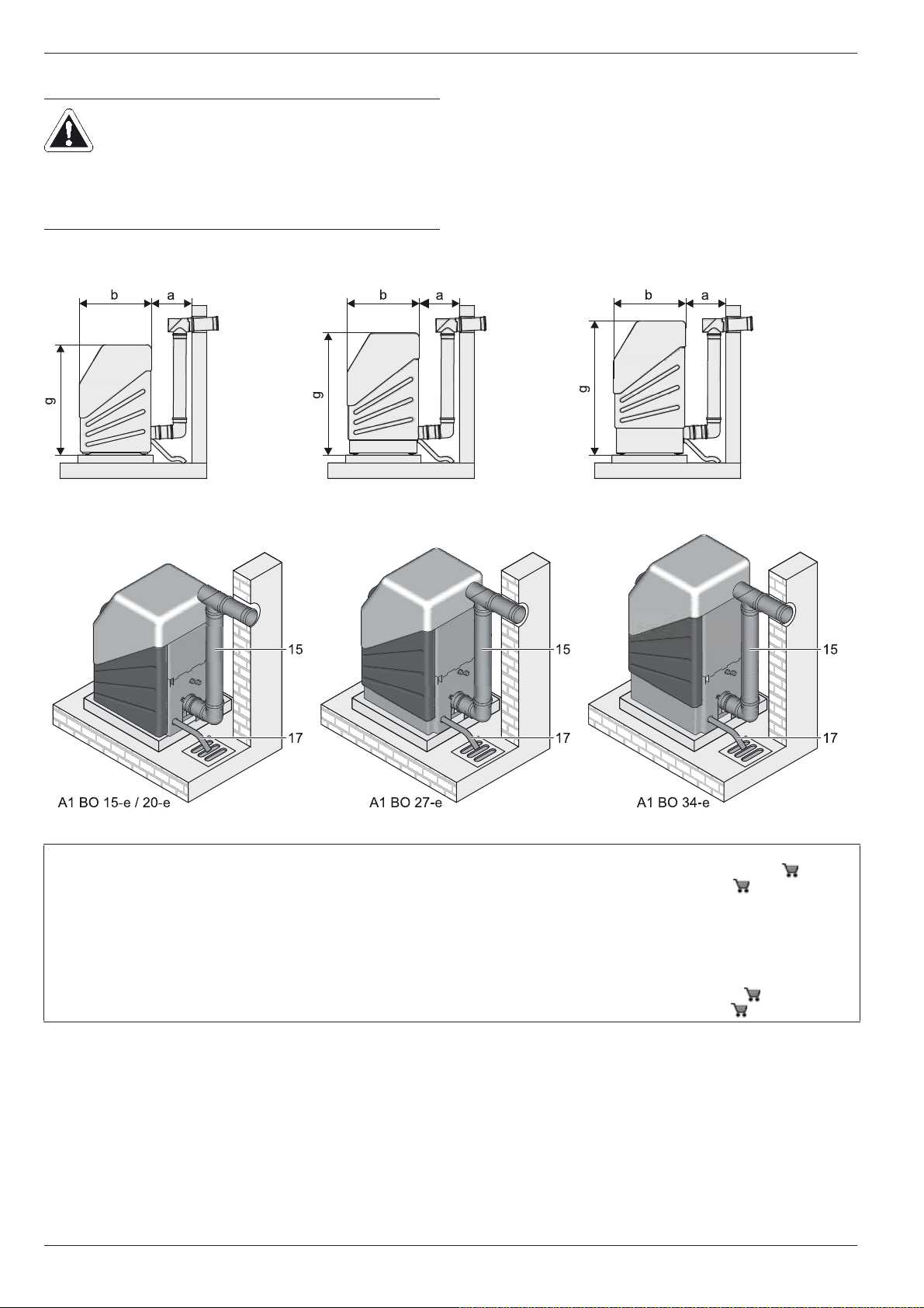
4.1 Dimensions and connection dimensions
Incorrect set-up and installation would render the manufacturer's
guarantee for the unit void. If you have questions, please contact
our Technical Customer Service.
Fig. 4-1 Dimensions of model variants, side view (legend see tab.4-1)
1 Boiler return (1" AG)
2 Boiler flow (1" AG)
3 Filling line connection on the KFE cock
(½" AG)
4 Flue gas/air intake connection (DN 80/125)
5 Connection expansion vessel
6 Burner
7 Safety valve
(½" IG, flue line ¾" IG)
8 3-way diverting valve
Tab. 4-1 Legend from fig. 4-1 to fig. 4-3
1)
2)
(1" AG)
1)
(½" IG)
9 Hot water (¾" IG)
10 Circulation (¾" IG)
1)
11 Heat exchanger return (¾" AG)
12 Sensor immersion sleeve
13 Heat exchanger flow (¾" AG)
14 Cold water (¾" IG)
15 Air/flue system (LAS) - Connection piece
(DN 80/125)
16 Air inlet hose (DN 50)
17 Condensate drain hose (DN 40)
8
A ROTEX A1 BO
B Boiler frame KU (15 30 21)
C Sub-tank US 150 ( 16 01 52)
AG Male thread
IG Female thread
a - k Dimension see tab. 4-2
1)
Accessory SGB A1 ( 15 60 18)
2)
Accessory VSA1 ( 15 48 22)
FA ROTEX A1 BOe - 02/2014
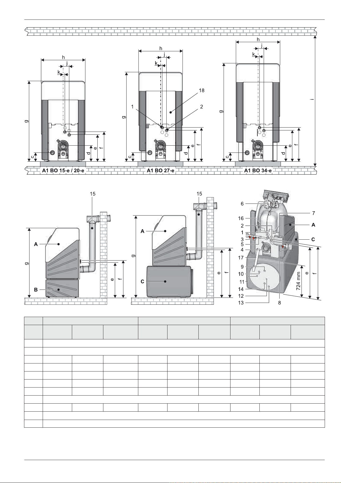
Fig. 4-2 Dimensions and connection dimensions - view from the rear (for legend see tab. 4-1)
4 x Set-up and installation
Fig. 4-3 D imensions and connection dimensions with boiler frame and sub-tank (for legend see tab. 4-1)
A1 BO 15-e / A1 BO 20-e A1 BO 27-e A1 BO 34-e
Dimen
sion
on the
floor
on the
sub-tank
on the boiler
frame
on the
floor
on the
sub-tank
on the
boiler frame
on the
floor
on the
sub-tank
on the boiler
frame
a 400
b 720
c135
d230
e365
f405
±15
±15
±15
±15
785
880
1000
1045
±15
±15
±15
±15
500
590
755
795
±15
±15
±15
±15
135
230
425
465
±15
±15
±15
±15
785
880
1065
1105
±15
±15
±15
±15
500
590
815
855
±15
±15
±15
±15
135
230
425
465
±15
±15
±15
±15
785
880
1065
1105
±15
±15
±15
±15
500
590
815
855
g 1100 1730 1480 1220 1850 1600 1340 1970 1720
h 625
i 1340 1890 1650 1470 2020 1770 1590 2140 1890
j85
k25
Tab. 4-2 Installation dimensions A1 BO in mm
±15
±15
FA ROTEX A1 BOe - 02/2014
±15
±15
±15
±15
9

4 x Set-up and installation
4.2 Different set-ups
1-8 Different set-ups (Description, see section 4.2.1 to
4.2.3)
CA Inlet air (combustion air)
FG Flue gas
RV Rear ventilation
Fig. 4-4 Installation variants for the Oil condensing boiler in series A1 BO
a Set up variant for room-air independent operation (flue gas/ inlet
air concentric)
b Set up variant for limited room-air independent operation (flue gas/
air inlet separate)
c Set up variant for room-air dependent operation
d Longitudinally ventilated shaft with fire resistance duration of
90 min (in residential buildings with low headroom 30 min).
Observe country-specific regulations for fire-resistance periods!
e Ventilation opening (1x150 cm² or 2x75 cm²)
f Rear ventilation opening (150 cm²)
10
FA ROTEX A1 BOe - 02/2014
4 x Set-up and installation
The Oil condensing boiler series A1 BO are basically designed
for operation in the room-air independent mode. They are fitted
with a concentric flue gas /air supply pipe DN 80/125.
Use of the ROTEX A1 BO in operation independent of
room air with concentric flue gas/air intake is recommended by ROTEX. If possible, choose this set-up!
In the event of limited room-air independent operation
(separate flue gas/ air intake) and in the event of roomair dependent operation, the installation room must
have a ventilation opening of at least 150 cm2 to the
outside.
This reduces the overall energy efficiency of the
building in the framework of the European Guideline
2010/31/EU: EPBD.
In some cases, the resonance in the flue system can
amplify the noise at the mouth of the flue gas pipe. The
noise level can be effectively reduced with the application of a silencer (E8 MSD, 15 45 78 bzw.
E11 MSD, 15 45 79).
Air suction noises are generated during ambient airdependent operation. The noise level can be effectively
reduced with the application of a silencer (G ZLSD,
15 45 77).
4.2.1 Operation independent of ambient air
Set-up version 1
The ROTEX A1 BO is connected to the chminey or a suitable
installation shaft using the concentric LAS connector line Set C
or Set D.
– The combustible air supply from the outside runs through the
chimney or through an installation shaft.
– The flue gas discharge using a flue gas pipe to the outside
runs through the same shaft as the air supply.
– Minimum distance between flue gas exit and roof ridge:
40 cm.
Set-up version 4
The ROTEX A1 BO is connected by the Set C or Set D
concentric LAS connection lines to the SET G exterior wall
system.
– The combustible air supply from the outside runs through the
ring-shaped gap in the dual tube, through the outer wall (suction from below).
– The flue gas discharge to the outside runs through a concen-
tric pipe, through the outer wall and then up to at least 40 cm
over the roof surface. In the external area, the outer air gap
serves as heat insulation for the flue gas pipe.
Set-up version 5
The ROTEX A1 BO is placed directly under the roof. Connected
with SET F.
– The combustible air supply and flue gas discharge run
through a concentric dual pipe.
– The combustible air supply from the outside runs through the
outer ring-shaped gap of the dual tube and the flue gas discharge to the outside runs through the inner tube.
– Minimum distance between flue gas exit and roof surface:
40 cm.
– Minimum height of the flue gas pipe: 2 m.
Set-up version 6
The ROTEX A1 BO does not stand directly under the roof. The
dual tube for the combustible air supply and flue gas pipe runs
through the roof truss.
– The combustible air supply and flue gas discharge run
through a concentric dual pipe (such as Set-up version 5).
– In the area of the roof truss, the dual tube for the combustible
air supply and the flue gas pipe must be laid through a protective pipe with sufficient fire resistance or be structurally separated from the roof truss.
4.2.2 Operation partially independent of ambient air
If the flue gas pipe is too high (see tab. 4-4), it may be advisable
to suction the supply air through a separate air supply line with
lower resistance.
The ROTEX A1 BO is operated with separately routed inlet air/
flue gas lines (2 line system).
– Combustion air inlet is routed from the outside via the ade-
quately sealed inlet air through the external wall. The air inlet
line should be sized so that the suction resistance at nominal power is less than 50 Pa.
– Flue gas dissipation to the outdoors is via the chimney or an
installation shaft. If the connection line between the ROTEX
A1 BO and the installation shaft is single-walled or is not completely surrounded by combustion air, a ventilation opening
of at least 150 cm
Appropriate measures must be taken to ensure that the
burner cannot be operated if the ventilation opening is closed.
– The installation shaft where the flue gas line runs must be rear
ventilated. In the lower area there must be a rear ventilation
opening of at least 150 cm
2
is required.
2
must be provided.
If the wall penetration is at a height of less than a meter
above the ground, ROTEX recommends introducing
the combusion air through a separate intake air pipe
(installation height: about 2 m). W8 ZR,
15 50 79.00 66 or W11 ZR, 15 50 77.00 30.
FA ROTEX A1 BOe - 02/2014
11
4 x Set-up and installation
The cross-section of the installation shaft must be sized so
that between the external wall of the flue gas line and the
internal face of the installation shaft the following minimum distance must be maintained:
– with a rectangular shaft cross-section: 2 cm
– with round shaft cross-section: 3 cm.
The rear ventilation opening must not be in rooms where a
positive pressure is generated (e.g. by controlled apartment
ventilation, a tumble-drier etc.).
Ɣ Pull off the air supply hose at the air supply connecting
manifold of the boiler body and connect the separate air
supply line.
Set-up version 3
– The combustible air supply from the outside runs through a
separate air supply line through the external wall.
– The flue gas discharge to the outside runs through the chim-
ney or through an installation shaft (as in set-up version 1).
Set-up version 8
The ROTEX A1 BO is connected by the SET A or SET B to a
ceramic chimney.
– The combustible air supply from the outside runs through a
separate air supply line through the external wall.
– Ceramic chimney for flue gas removal must be moisture-
insensitive (Class W) and suitable for overpressure operation
(Class P1 or H1), as well as having an appropriate constructional approval or CE approval with a declaration of conformity.
– If the ceramic chimney for the flue gas discharge does not
have an approval for overpressure operation, it must be possible to prove, using a flue gas calculation, that there is negative pressure in the shaft when the flue gas enters.
4.2.3 Ambient air dependent operation
The ROTEX A1 BO can also be connected in a manner dependent on ambient air. Thereby, only the inner flue gas pipe
(plastic pipe Ø 80 mm) of the concentric air-flue gas pipe is connected to the flue gas line. The device sucks the combustible air
from the installation room through the ring-shaped gap of the
jacket pipe.
For the flue gas routing to the outdoors, the shaft sizing and the
rear ventilation, the same conditions apply as in section 4.2.2.
A ventilation opening to the outside of 150 cm
In some cases, the resonance in the flue system can
amplify the noise at the mouth of the flue gas pipe. The
noise level can be effectively reduced with the application of a silencer (E8 MSD, 15 45 78 bzw.
E11 MSD, 15 45 79).
Air suction noises are generated during ambient airdependent operation. The noise level can be effectively
reduced with the application of a silencer (G ZLSD,
15 45 77).
2
is imperative.
Set-up version 7
The ROTEX A1 BO is connected by the SET A or SET B to a
ceramic chimney.
– Combustion air supply from the installation room.
– Ceramic chimney for flue gas removal must be moisture-
insensitive (Class W) and suitable for overpressure operation
(Class P1 or H1), as well as having an appropriate constructional approval or CE approval with a declaration of conformity.
– If the ceramic chimney for the flue gas discharge does not
have an approval for overpressure operation, it must be possible to prove, using a flue gas calculation, that there is negative pressure in the shaft when the flue gas enters.
4.3 Transport and delivery
CAUTION!
Lifting or pushing the Oil condensing boiler on the
cladding can damage the unit.
Ɣ Lift the ROTEX A1 BO only on the carrying straps
provided for this purpose.
The ROTEX A1 BO is delivered on a pallet. All industrial trucks,
such as lifting trucks and forklift trucks, are suitable for transporting it.
Scope of delivery
– ROTEX A1 BO (preassembled),
– Document pack,
– Toolkit (cleaning brush and scraper, burner chamber span-
ner, hexagonal spanner for burner and heat exchanger,
burner setting gauge).
Recommended accessory
– Safety group (SGB A1, 15 60 18) with pressure gauge,
safety valve, automatic bleeding, filling cock, connection fittings).
– Connection kit A1 (VSA1, 15 48 22), for hydraulic con-
nection of a heat exchanger (storage tank temperature sensor, 3-way diverter valve with actuating motor, connection fittings).
– External temperature sensor (RoCon OT1, 15 60 70), for
weather-controlled regulation.
Additional accessories see ROTEX price list.
Set-up version 2
– Combustion air supply from the installation room.
– Flue gas dissipation to the outdoors is via the chimney or an
installation shaft (such as Set-up version 1).
12
FA ROTEX A1 BOe - 02/2014
4 x Set-up and installation
4.4 Installing the Oil condensing boiler
4.4.1 Selecting the installation site
The installation location for the ROTEX A1 BO must meet the following minimum requirements.
Installation height
– The bottom edge of the condensate drain connection on the
unit must be higher than the outlet height of the condensate
drainage hose, otherwise condensation can accumulate in
the drain.
Ɣ If installing with adjacent storage tank, the boiler must be
installed on a plinth at least 80 mm high or a boiler support
frame (KU, 15 30 21).
Installation area
– The base is solid, even and horizontal, and has sufficient load
bearing strength. Install a pedestal if necessary.
– Observe the set-up dimensions (see section 4.1).
Installation room in general
– There are no special conditions for ventilation of the installa-
tion room for operation independent of the ambient air (using
a concentric air/flue system).
– In the event of limited room-air independent operation (sepa-
rate flue gas/ air intake) and in the event of room-air dependent operation, the installation room must have a ventilation
opening of at least 150 cm
goes via an installation shaft to the outside, it must be rear
ventilated (see section 4.2.2).
– For partial ambient air-independent and for ambient air-
dependent mode, the installation room must be free from
aggressive vapours (e.g. hair spray, perchloroethylene, carbon tetrachloride), heavy dust formation and high atmospheric humidity (e.g. washhouse).
Heating oil storage in the installation room
As a general rule, construction specifications allow up
to 5000 litres of heating oil to be stored in the installation room (according to the Firing Ordinance of the
state) if the building is in Building Category 1 and the
installation room is not a living room.
Set-up in the attic
If the ROTEX A1 BO is installed in the attic and the oil is stored
in the rooms below it, the oil pump of the burner is generally not
adequate. Since the vacuum on the suction side exceeds the
value of 0.4 bar, the oil must be supplied to the burner using a
separate pump. ROTEX strongly recommends using a suction
aggregate.
The minimum height of the flue gas pipe must be 2 m in order
to avoid malfunction at start or during operation of the burner.
2
to the outside. If the flue gas line
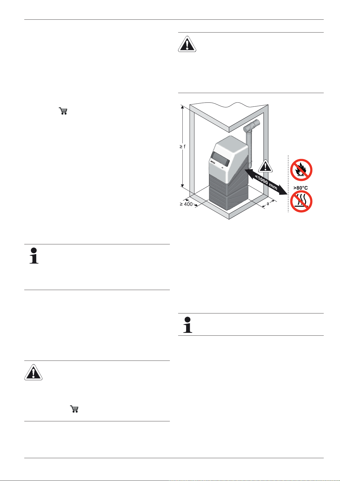
Surface temperature, minimum distance
WARNING!
The storage tank plastic wall on the ROTEX A1 BO
can melt under the effects of external heat (>80 °C)
and, in the extreme case, can catch fire.
Ɣ The ROTEX A1 BO can only be set up at a
minimum distance of 1 m from other sources of
heat (>80 °C, e.g. electric heaters, gas heaters,
chimneys).
Fig. 4-5 Minimum distance for the installation of the A1 BO
(for legend see tab. 4-2)
– When operating independently of the ambient air with nomi-
nal output, the design does not allow temperatures > 70 °C on
any component outside the unit panels. Therefore, no minimum distance is required to components made with flammable materials.
– A minimum distance of 50 mm between the flue gas duct and
flammable components should be maintained in a partial
room air-independent and ambient air-dependent mode (separate flue gas/air intake line).
– Do not store or use easily inflammable and easily combustible
substances directly next to the ROTEX A1 BO.
A flue gas temperature sensor connected to the
ROTEX A1 BO controller effects a safety shutdown if
the flue gas temperature is too high.
CAUTION!
If using a pressure aggregate, oil could escape if there
is a fault. Escaping oil can cause serious damage to
the environment.
Ɣ Install boiler in a leakproof tray and secure using a
float switch (connection through additional plug rail
(ZLÖ, 15 40 71).
Ɣ Use only a metallic filter cup (never Plexiglas).
FA ROTEX A1 BOe - 02/2014
13
4 x Set-up and installation
4.4.2 Setting up the unit
Precondition
– The installation site complies with the respective country-spe-
cific regulations, as well as the minimum requirements
described in section 4.4.1.
– Install a leakproof tray on site if using a pressure device and
secure the unit using a float switch.
Set-up
Ɣ Remove the packaging and dispose of it in an environmen-
tally sound manner.
Ɣ Install ROTEX A1 BO at the place of installation. Do not lift or
move the unit holding the panels.
Ɣ Position the ROTEX A1 BO so that it can be hinged open
without any restriction.
Observe the connection points of the oil hoses and the
mounting position of the oil filter, line routing of the heating
lines and the flue gas line.
Ɣ Check for the horizontal level and correct installation height of
the ROTEX A1 BO. You can adjust the height with the four
height-adjustable feet.
4.5 Air/flue system (LAS)
4.5.1 General instructions for flue system
WARNING!
There will be a risk of poisoning caused by flue gas
escaping within enclosed rooms that are inadequately
ventilated.
Ɣ Install only approved flue gas systems.
Ɣ The stipulated ventilation and rear ventilation must
be ensured, depending on the set up variant.
The Firing Ordinance of the respective state and EN 15287 are
valid for the model and dimensioning of the flue system.
Minimum requirements
For the design and dimensioning of the flue gas system, observe
all valid national combustion ordinances and country-specific
regulations.
Basically, for the flue gas system, you can use each flue gas pipe
according to EN 14471 with EU label, which meets the following
minimum requirements:
– Suitable for heating oil.
– Suitable for flue gas temperatures of at least 120 °C (temper-
ature class T120 or higher).
– Suitable for at least 200 Pa overpressure (pressure class P1
or H1).
– Humidity-resistant (condensation resistance class W).
– Sufficiently corrosion-resistant (corrosion resistance class 2).
The features of the flue system must be recognisable on the installed system.
Ɣ Place the nameplate of the flue system in the installation
room.
We recommend using the associated ROTEX flue gas
kits. ROTEX They satisfy all requirements and are also
fitted with special acid-proof seals.
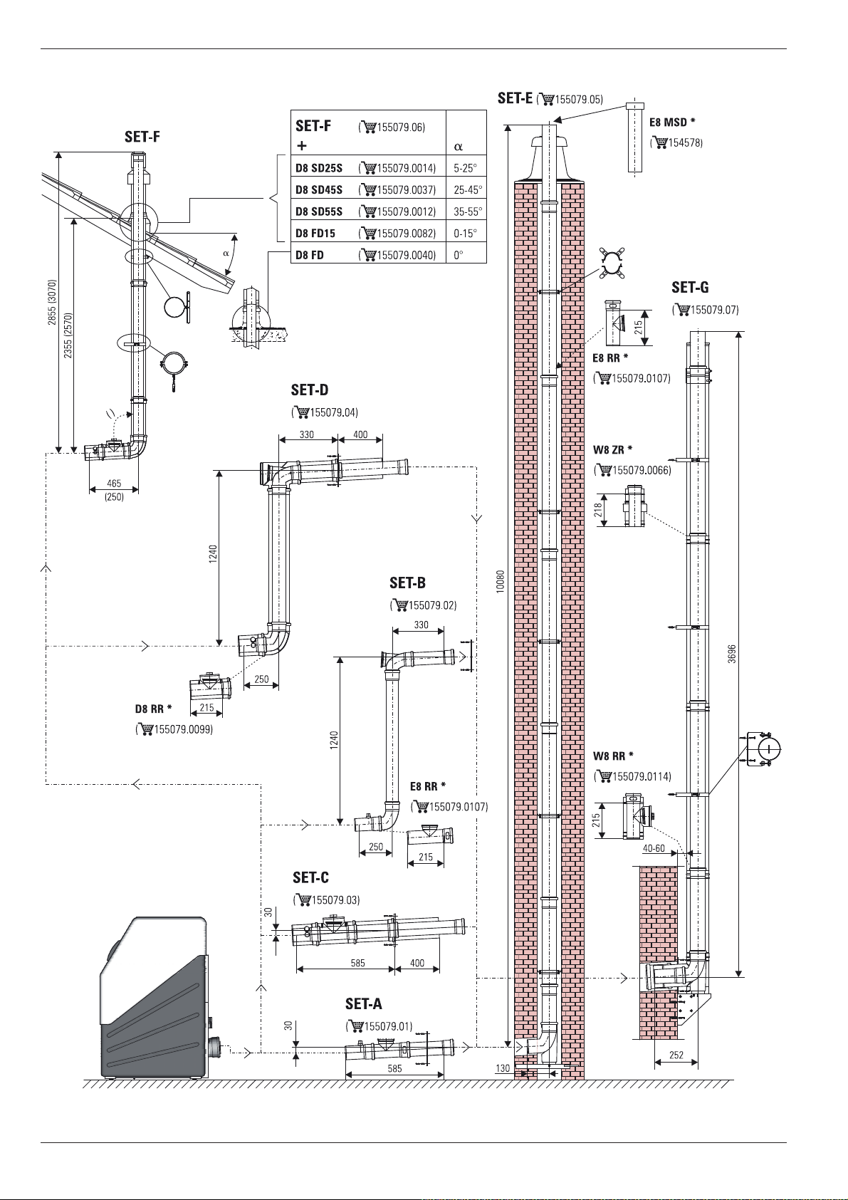
Type of connections
– Straight, directly towards rear: SET C, 15 50 79.03.
– Height offset, towards rear: SET D, 15 50 79.04.
– Direct roof penetration: SET F, 15 50 79.06.
For other details and connection dimensions for the three versions of the flue gas pipe, see section 4.5.3.
– Each flue gas line must be installed with a suitable test
adapter for checking and setting the combustion values. The
ROTEX LAS construction sets each include a test adapter
(D8 PA, 15 50 79.00 93).
Installation position and line height
– The maximum permitted flue gas counter pressure is 200 Pa.
The pressure loss in the supply line must not exceed 50 Pa.
– Angle of entry of the flue gas pipe into the chimney or instal-
lation shaft: 3°.
– Slope for horizontal parts of the flue gas pipe: 3°.
Counter-slopes are not allowed at any point in the flue gas
pipe.
– If the flue gas pipe needs more than 3 deflections >45°, then
the maximum permitted height for the flue gas pipe is reduced
by at least 1 m per deflection (flue gas calculations may be
needed).
– If the horizontal connecting piece is extended, the maximum
permitted height of the flue gas pipe is reduced by exactly that
length.
– Flexible flue gas lines must not be used in horizontal connec-
tion sections.
Flue gas system resistance
To ensure safe burner start-up and stable setting values, a
minimum resistance is required in the flue gas line. If this is not
achieved you need to fit a silencer (E8 MSD, 15 45 78 or
E11 MSD, 15 45 79).
Ɣ Switch the burner on (see chapter 15.2 "Emissions
measurement").
Ɣ Measure the resistance with a differential pressure
measurement unit on the flue gas measurement location
between the flue gas and intake air measurement openings
(differential pressure for the A1 BO 15/20 at least 0.5 mbar,
for the A1 BO 27/34 at least 1 mbar).
The tab. 4-3 and the tab. 4-4 show the maximum permissible
height of the flue gas line in the event that the ROTEX A1 BO is
operated in the nominal output range.
Set-up
version
(ref. fig. 4-4)
1)
1
1)
2
1)
3
4 161616
5 171717
6 171717
1) Cross section of the shaft: 135 mm x 135 mm
Tab. 4-3 Maximum permitted height of the flue gas pipe in m (when
operating in the nominal output range) - A1 BO 15-e to 27-e
A1 BO 15-e A1 BO 20-e A1 BO 27-e
DN 80 DN 80 DN 80
16 16 16
21 21 21
17 17 17
14
FA ROTEX A1 BOe - 02/2014
4 x Set-up and installation
Set-up
version
(ref. fig. 4-4)
1)
1
1)
2
1)
3
30 kW
DN 80
20 8 24
21 21 30
21 17 30
A1 BO 34-e
34 kW
DN 80
34 kW
DN 110
4202028
5111123
6111123
1 Shaft cross section for DN 80: 135 mm x 135 mm; Shaft cross section for
DN 110: 160 mm x 160 mm
Tab. 4-4 Maximum permissible height of the flue gas line in m
(when
operating in nominal output range) - A1 BO 34-e
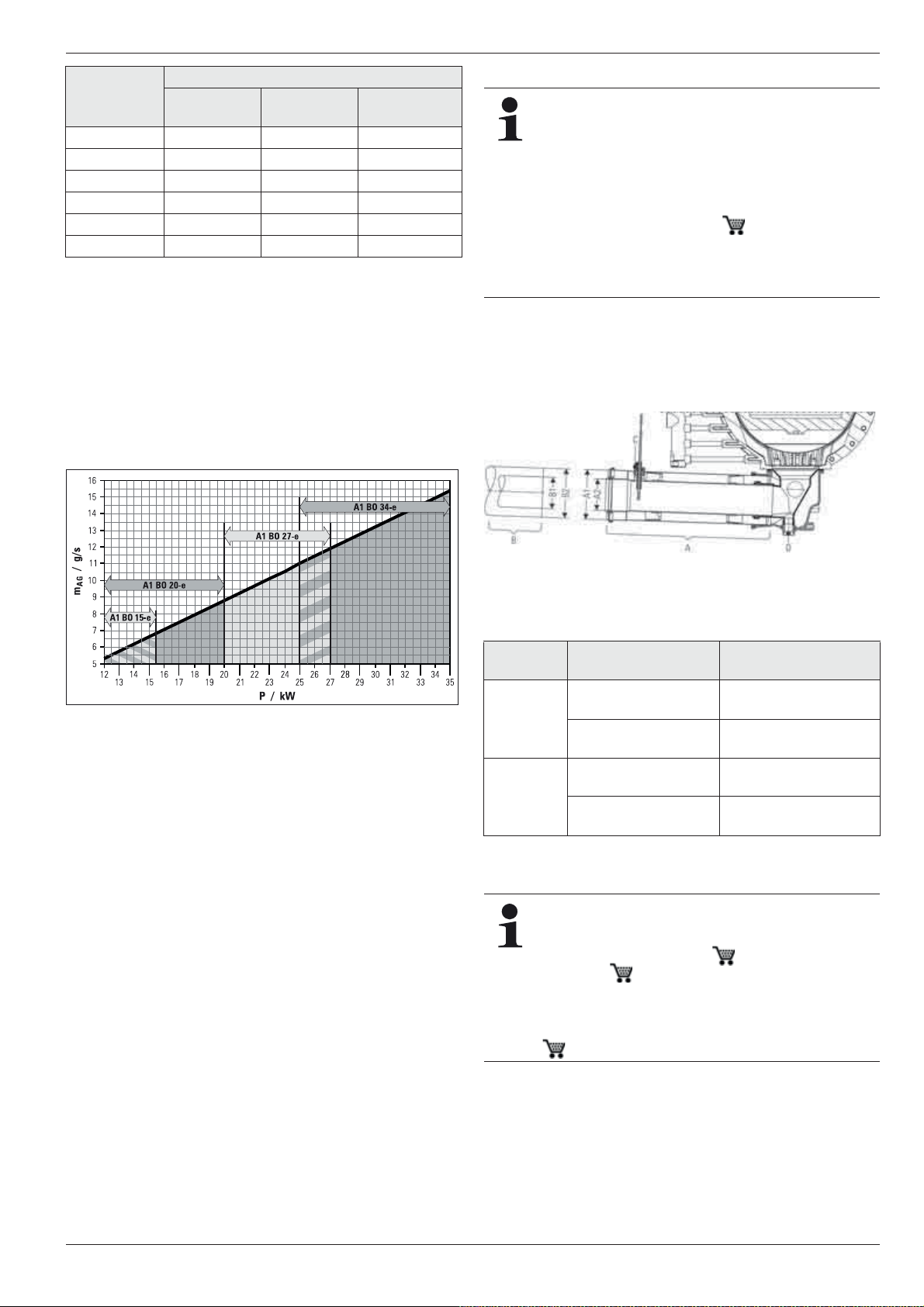
Any restriction on the output range may require a recalculation of
the maximum permitted height for the flue gas pipe. The characteristics for the flue gas calculation can be obtained from fig. 4-6
and chapter 15.2 "Emissions measurement".
The flue gas mass flow of the systems depends on the burner
output set.
Connection
Basically, any flue gas line that complies with the
minimum requirements according to the EN 14471 and
that has the CE-labelling can be connected (see
section 4.5.1).
Each flue gas line must be installed with a suitable test
adapter for checking and setting the combustion
values. The ROTEX LAS construction sets each include a test adapter (D8 PA, 15 50 79.00 93).
We recommend the use of the associated ROTEX flue
gas set (see fig. 4-8). They satisfy all requirements and
are also fitted with special acid-proof seals.
Ɣ Connect ROTEX A1 BO to the flue gas system within the
place of installation (for pipe dimensions, see fig. 4-2 or
fig. 4-7).
Ɣ Place the nameplate of the flue gas pipe in the installation
room.
mAGFlue gas mass flow P Burner output
Fig. 4-6 Flue gas mass flow in relation to the burner output
4.5.2 Connecting the flue gas line to the ROTEX A1
BO
Requirements
– The flue system fulfils the requirements described in
section 4.5.1.
– The flue system fulfils any other required national or regional
safety requirements.
– The ROTEX A1 BO is installed correctly.
A Boiler connection
B Flue gas connection
Fig. 4-7 Connection dime nsions for LAS connection to the ROTEX
Connection
A1 BO
Connection Connection dimension
side
A Boiler side A1 Flue gas DN 80
Collar
A2 Supply air DN 125
Collar
B Flue gas
B1 Flue gas DN 80 Outside diameter
side
B2 Supply air DN 125 Outside diameter
Tab. 4-5 Connection dimensions for LAS connection to the ROTEX
A1 BO
C Flue gas temperature sensor
D Connection for condensate drain
in mm
Inside diameter
+0.8
= 80.4
Inside diameter
= 127.0
= 80.0
= 126.0
-0.5
+0.3
±0.3
In some cases, the resonance in the flue system can
amplify the noise at the mouth of the flue gas pipe. The
noise level can be effectively reduced with the application of a silencer (E8 MSD, 15 45 78 bzw.
E11 MSD, 15 45 79).
Air suction noises are generated during ambient airdependent operation. The noise level can be effectively
reduced with the application of a silencer (G ZLSD,
15 45 77).
FA ROTEX A1 BOe - 02/2014
15
4 x Set-up and installation
4.5.3 Flue gas system kits
Fig. 4-8 Flue gas system components (* if necessary)
16
FA ROTEX A1 BOe - 02/2014
Additional kits
– Flue gas connection to a duct system (rigid flue gas line
SET E or flexible flue gas line SET O)
– Flue gas connection for exterior wall line (SET G)
If necessary, additionally needed concentric LAS pipes for increased roof or ceiling heights, single wall PP pipes for chimney
heights of more than 10 m or additional accessory components
must be ordered.
4.6 Water connection
The ROTEX A1 BO has a common flow and common return for
the heating circuit and storage tank filling. The connections are
placed on the rear of the unit (refer to fig. 3-2).
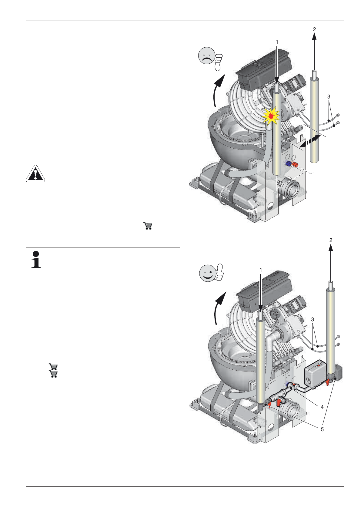
For maintenance, it must be possible to swing the boiler up with
the burner mounted. During installation of the flow and return
lines leading upwards, sufficient free space must be provided for
swinging the boiler up.
Instructions for water connection
CAUTION!
If the ROTEX A1 BO is connected to a heating system
in which the pipelines or heating elements are made of
steel or non-diffusion-sealed floor heating pipes,
sludge and shavings may enter the boiler and lead to
blockage, local overheating or corrosion damage.
Ɣ Rinse out the heat distribution network (in the
existing heating system).
Ɣ Install the sludge separator (SAS1, 15 60 21),
in the heating return.
4 x Set-up and installation
Fig. 4-9 Heating lines installing (Wrong)
In accordance with EN 12828 you must install a safety
valve in the flow line, on or in the immediate vicinity of
the heat exchanger, with which you can limit the maximum permissible operating pressure in the heating system. There should be no hydraulic blocking elements
between the heat generator and the safety valve.
Any steam or heating water which may escape must be
diverted by a suitable blow-off line with constant gradient in a frost-protected, safe and observable manner.
A diaphragm expansion vessel of adequate dimensions
and pre-set for the heating system must be connected
to the return line. There should be no hydraulic blocking
elements between the heat generator and the diaphragm expansion vessel.
ROTEX recommends using, for the hydraulic connection of the A1 BO, the safety group (SBG A1,
15 60 18) and the connection kit (VSA1,
15 48 22).
Ɣ Connect the blow-off line to the safety over-pressure valve
and diaphragm expansion vessel in accordance with
EN 12828.
Ɣ Connect the water for filling or refilling the heating system as
specified by EN 1717 to avoid contamination of drinking water
by backwash.
The line should be routed so that the upper half of the burner
chamber of the ROTEX A1 BO can be hinged open without any
problems after installation (fig. 4-10).
FA ROTEX A1 BOe - 02/2014
Fig. 4-10 Heating lines installing (Right)
17
4 x Set-up and installation
– Water shortage protection: The overheating protection of
the ROTEX A1 BO safely shuts off the Oil condensing boiler
in case of lack of water and locks it. No additional water shortage protection is needed in the construction.
– Avoid damages caused by deposits and corrosion:
Observe the relevant regulations of technology to prevent
creation of corrosion products and deposits.
Measures for desalination, softening or hardness stabilization
are necessary, if the filling and top-up water have a high total
hardness (>3 mmol/l - sum of the calcium and magnesium
concentrations, calculated as calcium carbonate.
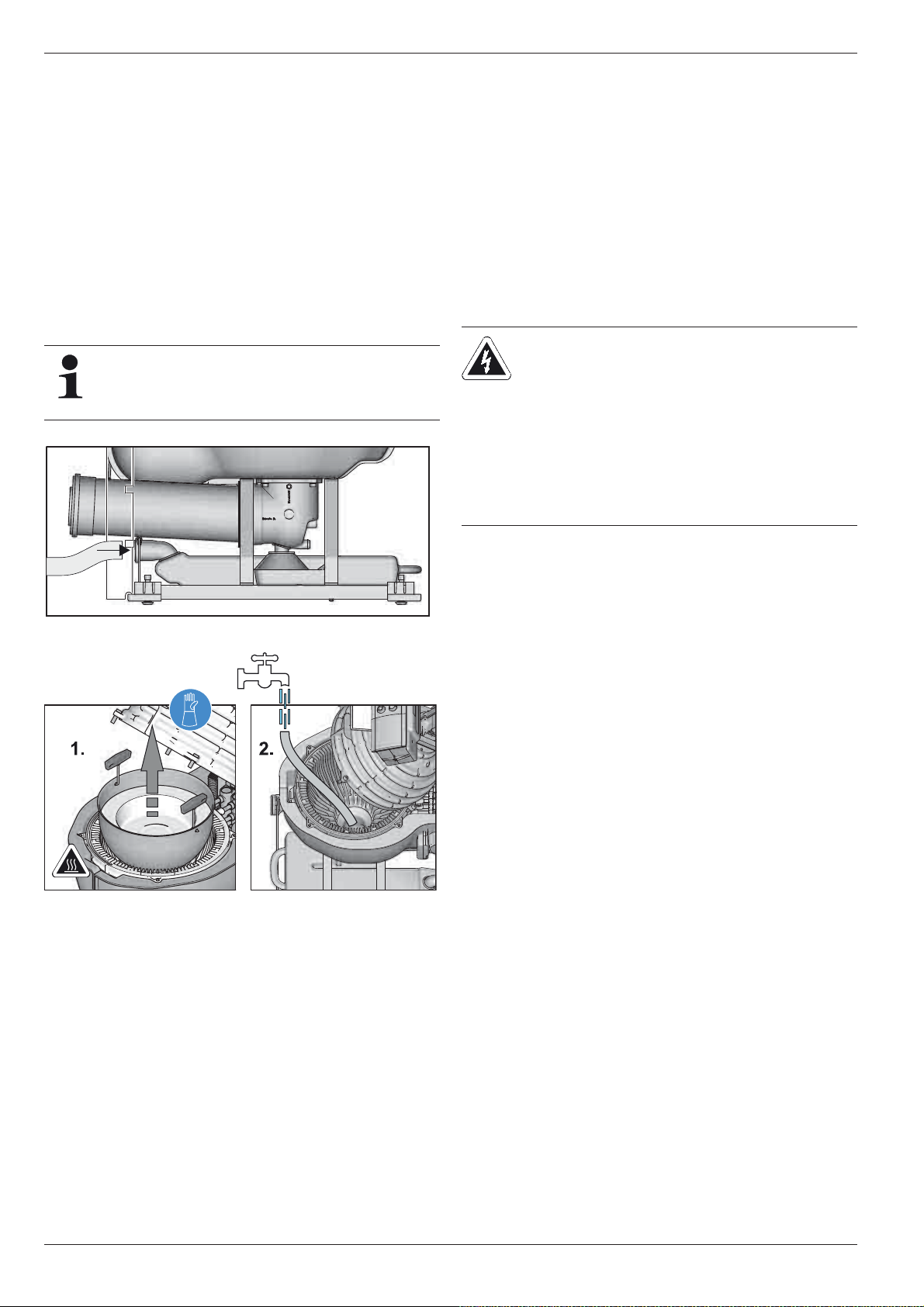
4.7 Connect the condensate drain
The condensation generated in oil condensing technology has a
pH value between 1.8 and - 3.7.
Depending on the regulations of the community waste
water regulations, neutralisation can be dispensed with,
if the condensing boiler is operated exclusively with
low-sulphur heating oil EL.
Ɣ Fill the condensate box with water in order to prevent flue gas
from escaping into the installation room. To do this, either:
– Open the boiler body and lift out the combustion chamber
insert (see section 9.2.5); top up condensate pipe using a
hose (see fig. 4-12) or,
– Unscrew the inspection lid of the connecting piece of the
flue gas pipe and fill the condensate box by using a hose
held in the flue gas pipe.
Ɣ Check the condensate drain section for leakage.
4.8 Establish connection and electrical
equipment
4.8.1 Instructions concerning electrical connection
WARNING!
Live parts can cause an electric shock on contact and
cause fatal burns or injuries.
Ɣ Before beginning work on live parts, disconnect
them from the power supply (switch off fuse, main
switch) and secure against unintentional restart.
Ɣ The electrical connection should only be
performed by electrical engineers in compliance
with valid standards and guidelines as well as the
specifications of the energy supply company.
Fig. 4-11 Connecting the condensate drain hose
Fig. 4-12 Fill condensate box with water
Connection
The condensate box is factory-assembled in the boiler cradle and
connected to the flue gas connecting piece of the boiler. The connection to the wastewater network is designed for HT piping
DN 40.
Ɣ Lay the condensate drain sloping down from the boiler so that
condensation will not accumulate in the flue gas manifold.
Ɣ In order to avoid accumulation in the flue gas connection of
the boiler, make sure that no siphon is formed between the
condensate drainage hose and the connection with the
wastewater line.
All electronic control and safety systems of the ROTEX A1 BO
are connected and tested. Modifications on the electrical installation are dangerous and prohibited. The operator alone shall
bear responsibility for any resulting damage.
A 3 m flexible cable is already connected inside the unit and
placed in the control panel on the connecting circuit board. Only
the external temperature sensor and other optional applications
(e.g. storage tank sensor, circulation pump) still have to be connected to the boiler control panel.
4.8.2 Establishing the electrical connection
Ɣ Check the supply voltage (~230 V, 50 Hz).
Ɣ Disconnect the junction box of the domestic installation.
Ɣ Connect the mains connection of the ROTEX A1 BO to the
junction box of the domestic insulation. Ensure that the
polarity is correct.
Ɣ Restore power supply to the junction box of the domestic
electrical installation.
18
FA ROTEX A1 BOe - 02/2014
 Loading...