

Page 1

7
LF45/55 series
STRUCTURE
TECHNICAL DATA
0
DIAGNOSTICS
1
STEERING GEAR, GENERAL
2
STEERING BOX
3
STEERING PUMP
4
RESERVOIR AND LINES
5
FRONT AXLE, F36/F48
FRONT AXLE, F60
FRONT AXLE, 152N
STEERED TRAILING SWIVEL AXLE
6
7
8
9
ᓻ 200322
Page 2

Page 3

7
TECHNICAL DATA
LF45/55 series Contents
CONTENTS
Page Date
1. STEERING GEAR, GENERAL 1-1 200322........................................... ....
1.1 General 1-1 200322......................................................... ....
2. STEERING BOX 2-1 200322....................................................... ....
2.1 General 2-1 200322......................................................... ....
2.2 Tightening torques 2-2 200322................................................ ....
3. STEERING PUMP/RESERVOIR 3-1 200322......................................... ....
3.1 General 3-1 200322......................................................... ....
3.2 Tightening torques 3-1 200322................................................ ....
4. F36 AND F48 FRONT AXLE 4-1 200322............................................ ....
4.1 General 4-1 200322......................................................... ....
4.2 Tightening torques 4-3 200322................................................ ....
5. F60 FRONT AXLE 5-1 200322..................................................... ....
5.1 General 5-1 200322......................................................... ....
5.2 Tightening torques 5-3 200322................................................ ....
6. 152N FRONT AXLE 6-1 200322.................................................... ....
6.1 General 6-1 200322......................................................... ....
6.2 Tightening torques 6-7 200322................................................ ....
7. STEERED TRAILING SWIVEL AXLE 7-1 200322.................................... ....
7.1 General 7-1 200322......................................................... ....
7.2 Tightening torques 7-3 200322................................................ ....
0
ᓻ 200322
1
Page 4

0
7TECHNICAL DATA
Contents LF45/55 series
2
ᓻ 200322
Page 5

7
TECHNICAL DATA
LF45/55 series Steering gear, general
1. STEERING GEAR, GENERAL
1.1 GENERAL
Steered axles
Vehicle type
LF45 6 and 8 tonnes F36 N/A
LF45 10, 11 and 12 tonnes F48 N/A
LF55 12, 13, 14 and 15
LF55 FAN 12, 13, 14 and 15
LF55 16 and 18 tonnes 152N N/A
Steering box
Vehicle type
LF45 6 and 8 tonnes ZF8090 130 + 10 bar
LF45 10, 11 and 12 tonnes ZF8090 180 + 10 bar
LF55 12, 13, 14 and 15
GVW Front axle Trailing axle
F60 N/A
tonnes
F60 Steered trailing swivel
tonnes
GVW Steering box Max. system
ZF8095 150 + 10 bar
tonnes
axle (F60)
pressure
0
LF55 FAN 12, 13, 14 and 15
tonnes
LF55 16 and 18 tonnes ZF8098 150 + 10 bar
Circulation pressure
Maximum permissible circulation pressure of
the steering gear at a steering-oil temperature
of 50_C
Final limiting pressure
Final limiting pressure at a steering-oil
temperature of 50_C and an engine speed of
1200-1400 rpm
Steering box internal leaks
Maximum permissible internal leakage in the
steering box
ZF 8090 steering box 2.0 l/min.
ZF 8095 and 8098 steering box 2.5 l/min.
ZF8095 150 + 15 bar
10 bar max.
40-45bar
ᓻ 200322
1-1
Page 6

0
TECHNICAL DATA
7
Steering gear, general LF45/55 series
Steering box internal play
Maximum permissible internal play of the
steeringboxwithablockedpitmanarm
Steering pump
LF45 series ZF 7684 steering pump
LF55 series, other vehicles ZF 7685 steering pump
LF55 series FAN version ZF 7687 steering pump
Steering pump output
Steering pump output at a steering oil
temperature of 50_C and pressure of 50 bar,
at idling speed
ZF 7684 steering pump 5.9 l/min. minimum
ZF 7685 steering pump 7.0 l/min. minimum
ZF 7687 steering pump 10.8 l/min. minimum
Steering pump output at a steering oil
temperature of 50_C, pressure of 50 bar and
an engine speed of approx. 1300 1400 rpm
ZF 7684 steering pump 8.0 - 10.4 l/min.
ZF 7685 steering pump 16.0 - 20.8 l/min.
ZF 7687 steering pump 22.5 - 27.5 l/min.
4 cm steering wheel deflection
1-2
ᓻ 200322
Page 7

7
TECHNICAL DATA
LF45/55 series Steering box
2. STEERING BOX
2.1 GENERAL
Steering box
Version: single-circuit steering box with automatic
bleeding, self-adjusting wheel-deflection
limiting valves and pressure-limiting valve.
Type:
ZF 8090 used on F36 and F48 front axle.
ZF 8095 used on F60 front axle.
ZF 8098 used on 152N front axle.
Pressure point
Resistance increase in the pressure point
ZF 8090 20 - 60 Ncm
ZF 8095 20 - 80 Ncm
ZF 8098 20 - 100 Ncm
Input shaft end play
ZF 8090 0.005 - 0.025 mm
ZF 8095 0.010 - 0.030 mm
ZF 8098 0.020 - 0.040 mm
0
ᓻ 200322
2-1
Page 8
TECHNICAL DATA
7
Steering box LF45/55 series
2.2 TIGHTENING TORQUES
0
The tightening torques stated in this section are
different from the standard tightening torques
included in the overview of standard tightening
torques. Any other threaded connections that
are not specified must therefore be tightened to
the tightening torque stated in the overview of
standard tightening torques.
When attachment bolts and nuts are to be
replaced, it is important - unless stated
otherwise - that these bolts and nuts are of
exactly the same length and property class as
the ones removed
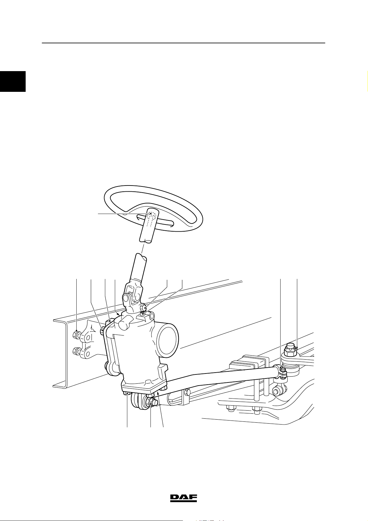
LF45 steering gear
.
E
A B CD G
F
IJG
IH
S7 00 884
2-2
ᓻ 200322
Page 9

7
TECHNICAL DATA
LF45/55 series Steering box
A. Attachment bolts/nuts, steering bracket
on M12 10.9 chassis
Stud bolt in steering bracket 80 Nm
B. Bolts/nuts for attaching the steering box
to the steering bracket
Stud bolt in steering box 180 Nm
C. Pitman-arm attachment nut 350 Nm
D. Pressure-limiting valve 30 Nm
E. Steering wheel attachment bolt 50 Nm
F. Attachment bolt/nut, steering column
universal joint
G. Wheel-deflection limiting valve stop bolt 15 Nm
H. Attachment bolt, steering-rod clamping
bracket
I. Steering rod castle nut 180 Nm
J. Cover attachment bolt 135 Nm
(1) Always use new attachment bolts.
(2) Use new original attachment bolt and nut.
(3) Tighten until the split pin fits (max. 60_).
according to standard
400 Nm
56 Nm
48 Nm
(1)
(2)
(3)
0
ᓻ 200322
2-3
Page 10
0
TECHNICAL DATA
Steering box LF45/55 series
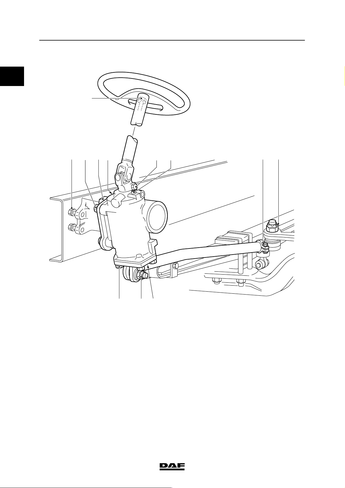
LF55 steering gear
E
7
A B CD G
F
IJG
IH
S7 00 884
2-4
ᓻ 200322
Page 11

7
TECHNICAL DATA
LF45/55 series Steering box
A. Attachment bolts/nuts, steering bracket
on M14 10.9 chassis
Stud bolt in steering bracket 125 Nm
B. Bolts/nuts for attaching the steering box
to the steering bracket
Stud bolt in steering box 180 Nm
C. Pitman-arm attachment nut
- with ZF8095 steering box 520 Nm
- with ZF8098 steering box 570 Nm
D. Pressure-limiting valve 30 Nm
E. Steering wheel attachment bolt 50 Nm
F. Attachment bolt/nut, steering column
universal joint
G. Wheel-deflection limiting valve stop bolt 15 Nm
H. Attachment bolt, steering-rod clamping
bracket
- with F60 front axle 65 Nm
- with 152N front axle 90 Nm
I. Steering rod castle nut 220 Nm
J. Cover attachment bolt
- with ZF8095 steering box 285 Nm
- with ZF8098 steering box 189 Nm
according to standard
560 Nm
56 Nm
(1)
(2)
(3)
0
(1) Always use new attachment bolts.
(2) Use new original attachment bolt and nut.
(3) Tighten until the split pin fits (max. 60_).
ᓻ 200322
2-5
Page 12

0
TECHNICAL DATA
Steering box LF45/55 series
7
2-6
ᓻ 200322
Page 13

7
TECHNICAL DATA
LF45/55 series Steering pump/reservoir
3. STEERING PUMP/RESERVOIR
3.1 GENERAL
Steering pump
Design vane pump
Type ZF 7684, ZF 7685, ZF 7687
Maximum pressure see steering box type plate
(Pump does not have pressure-limiting valve.)
3.2 TIGHTENING TORQUES
The tightening torques stated in this section are
different from the standard tightening torques
included in the overview of standard tightening
torques. Any other threaded connections that
are not specified must therefore be tightened to
the tightening torque stated in the overview of
standard tightening torques.
When attachment bolts and nuts are to be
replaced, it is important - unless stated
otherwise - that these bolts and nuts are of
exactly the same length and property class as
the ones removed
Steering pump attachment bolts 46 Nm
Flow-control valve plug 65 Nm
Delivery pipe connection in the pump 36 Nm
Cover attachment bolts 20 Nm
Reservoir attachment bolts 8 Nm
.
0
ᓻ 200322
3-1
Page 14

0
TECHNICAL DATA
Steering pump/reservoir LF45/55 series
7
3-2
ᓻ 200322
Page 15
7
TECHNICAL DATA
LF45/55 series F36 and F48 front axle
4. F36 AND F48 FRONT AXLE
4.1 GENERAL
Axle journal
Anti-corrosion agent Gleitmo 805
Wheel speed sensor
Anti-corrosion agent Molykote P37
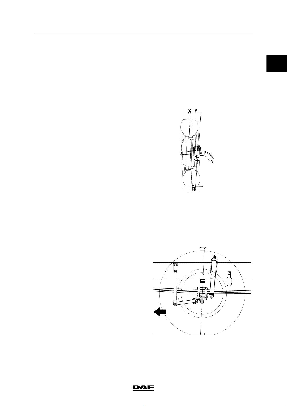
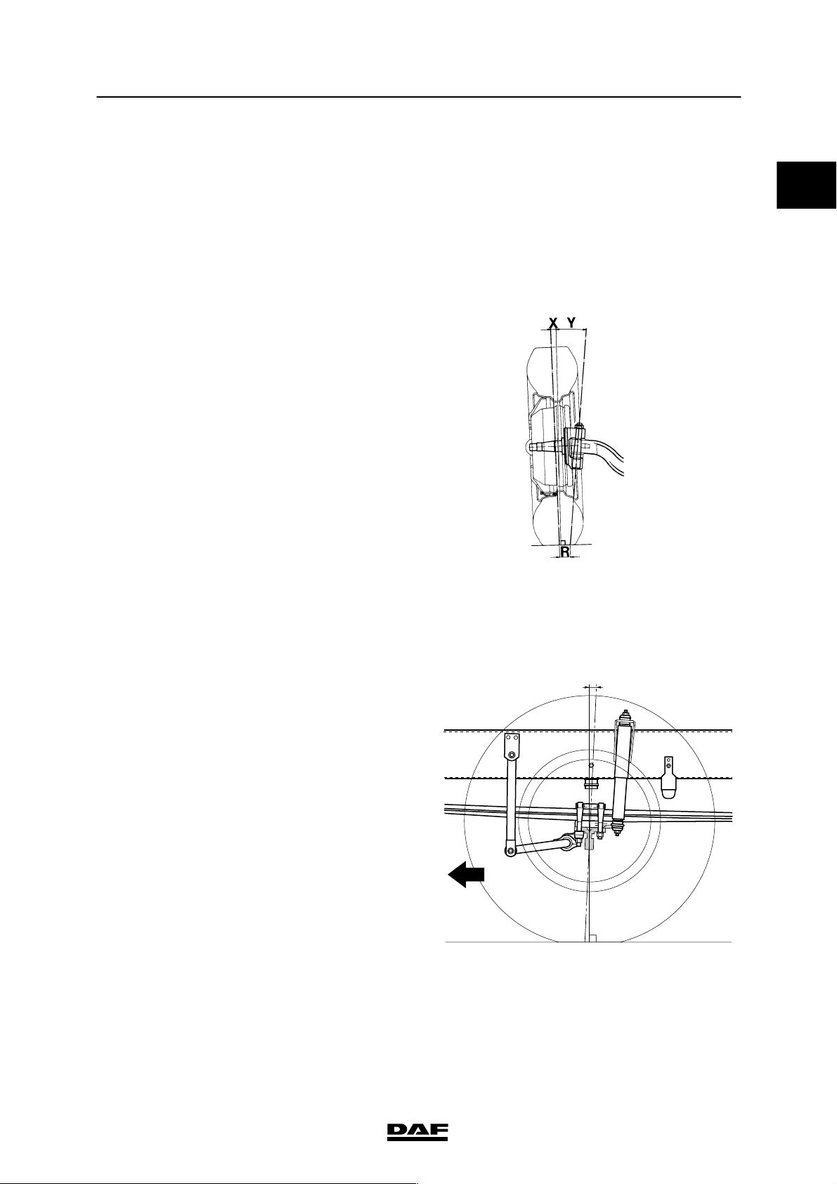
Camber angle and kingpin inclination (KPI)
Camber angle (X) on an
unloaded axle
King-pin inclination (Y) 7_
0_30′
0
S7 00 129
Wheel deflection
Maximum inner wheel
deflection
- F36 axle 53_
- F48 axle 53_
Caster
Z=caster
- F36 axle 4_
- F48 axle 4_
Z
S7 00 607
ᓻ 200322
4-1
Page 16

0
TECHNICAL DATA
7
F36 and F48 front axle LF45/55 series
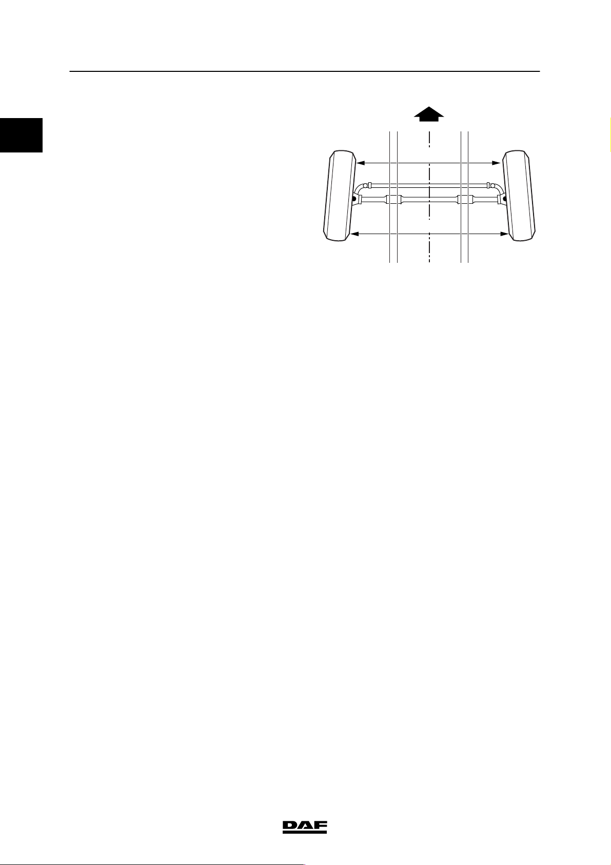
Toe
Measured at the side walls of the tyre (B -- A)
in unloaded condition
- F36 axle, toe-in 0 - 1.6 mm
- F48 axle, toe-in 0 - 1.6 mm
A
B
S7 00 833
Steering ball joints
Axial play max. 1.5 mm
Swivel axle
Axial play
- F36 axle 0.05 - 0.12 mm
- F48 axle 0.05 - 0.12 mm
List of shim sizes (thickness) for adjusting
swivel axle play
Hub
Wheel bearing play
- F36 axle 0.05 -0.20 mm
- F48 axle 0.05 -0.20 mm
0.05 mm
0.125 mm
0.25 mm
1.00 mm
4-2
ᓻ 200322
Page 17

7
TECHNICAL DATA
LF45/55 series F36 and F48 front axle
4.2 TIGHTENING TORQUES
The tightening torques stated in this section are
different from the standard tightening torques
included in the overview of standard tightening
torques. Any other threaded connections that
are not specified must therefore be tightened to
the tightening torque stated in the overview of
standard tightening torques.
When attachment bolts and nuts are to be
replaced, it is important - unless stated
otherwise - that these bolts and nuts are of
exactly the same length and property class as
the ones removed
.
0
ᓻ 200322
4-3
Page 18
TECHNICAL DATA
;;;;
;;;;
;;;;
;;;;
;;;;
;;;;
;
;
;;
;;
;
;
;;
;;
;;
7
F36 and F48 front axle LF45/55 series
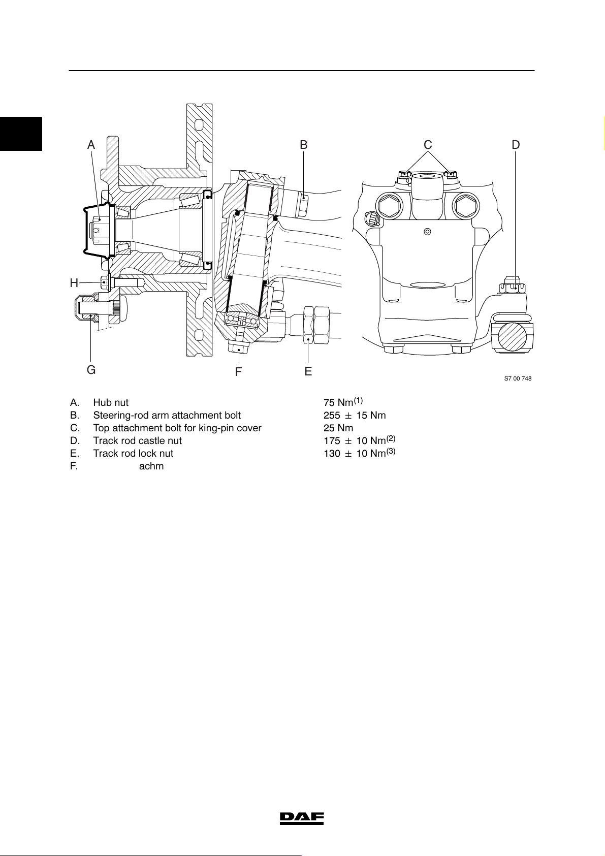
0
A
B
H
G
F
A. Hub nut 75 Nm
B. Steering-rod arm attachment bolt 255 ᐔ 15 Nm
C. Top attachment bolt for king-pin cover 25 Nm
D. Track rod castle nut 175 ᐔ 10 Nm
E. Track rod lock nut 130 ᐔ 10 Nm
F. Bottom attachment bolt for king-pin cover 120 ᐔ 5Nm
G. Wheel nut
- F36 axle (M18 x 1.5) 370 ᐔ 30 Nm
- F48 axle (M20 x 1.5) 485 ᐔ 35 Nm
H. Hub attachment bolt 115 ᐔ 5Nm
E
(1)
DC
S7 00 748
(2)
(3)
(4)
(4)
(1) Turn the nut anticlockwise (approx. 90_) until the
specified wheel bearing play is achieved. Lock with
split pin.
(2) Tighten until the split pin fits (max. 60_).
(3) Lock nut using locking plate.
(4) Retighten after 100 km. If new wheel bolts have been
fitted, the wheels need additional retightening after
500 km.
4-4
ᓻ 200322
Page 19
7
TECHNICAL DATA
LF45/55 series F60 front axle
5. F60 FRONT AXLE
5.1 GENERAL
Axle journal
Anti-corrosion agent Gleitmo 805
Wheel speed sensor
Anti-corrosion agent Molykote P37
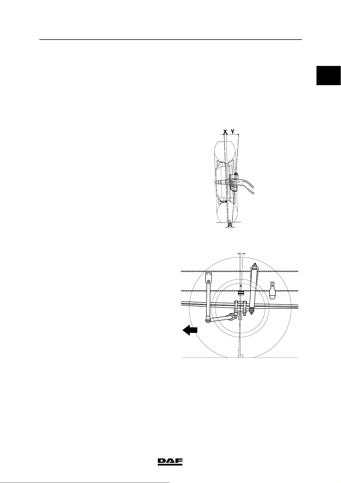
Camber angle and kingpin inclination (KPI)
Camber angle (X) on an
unloaded axle
King-pin inclination (Y) 7_15′
0_30′
0
S7 00 129
Wheel deflection
Maximum inner wheel
deflection
Caster
Z=caster 3_
50_
Z
S7 00 607
ᓻ 200322
5-1
Page 20
0
TECHNICAL DATA
7
F60 front axle LF45/55 series
Toe
Measured at the side walls of the tyre (B -- A)
in unloaded condition
Toe-in 0 - 1.6 mm
A
B
S7 00 833
Steering ball joints
Axial play max. 1.5 mm
King pin
Press-in force 150 kN
5-2
ᓻ 200322
Page 21

7
TECHNICAL DATA
LF45/55 series F60 front axle
5.2 TIGHTENING TORQUES
The tightening torques stated in this section are
different from the standard tightening torques
included in the overview of standard tightening
torques. Any other threaded connections that
are not specified must therefore be tightened to
the tightening torque stated in the overview of
standard tightening torques.
When attachment bolts and nuts are to be
replaced, it is important - unless stated
otherwise - that these bolts and nuts are of
exactly the same length and property class as
the ones removed
.
0
ᓻ 200322
5-3
Page 22
;;;
;;;
;;
;;
;;
;;
;;
;;
;;;
;;;
;;
;;
;;
;
;
;
;
;;
;;
;
0
TECHNICAL DATA
7
F60 front axle LF45/55 series
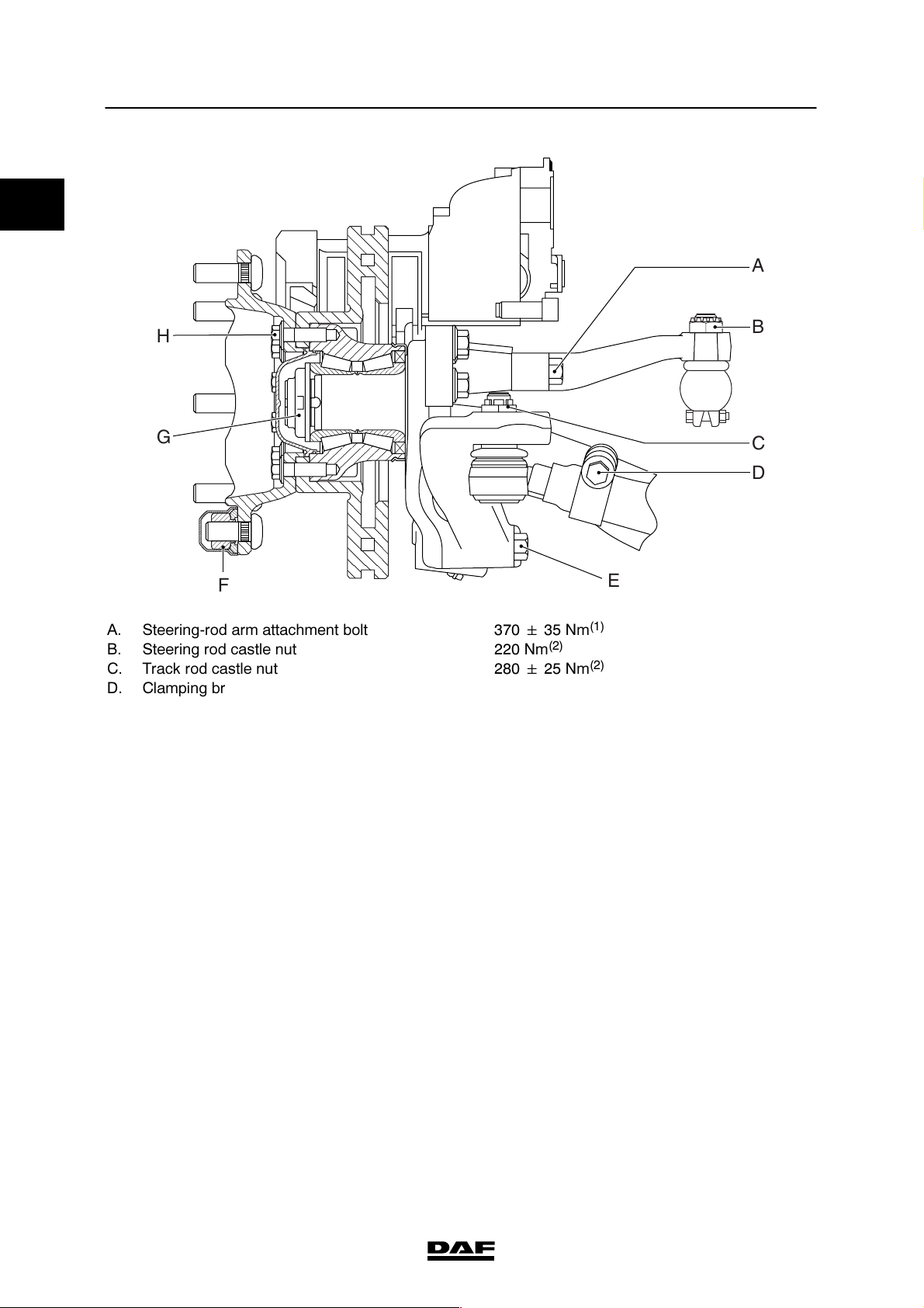
A
H
G
F
A. Steering-rod arm attachment bolt 370 ᐔ 35 Nm
B. Steering rod castle nut 220 Nm
C. Track rod castle nut 280 ᐔ 25 Nm
D. Clamping bracket attachment bolt 80 ᐔ 10 Nm
E. Track-rod arm attachment bolt 420 ᐔ 40 Nm
F. Wheel nut (M20 x 1.5) 485 ᐔ 35 Nm
G. Hub nut
st
-1
phase 300 Nm
-2ndphase turn the hub through 10 rotations
-3rdphase 350 Nm
th
-4
phase turn the hub through 10 rotations
-5thphase 685 ᐔ 65 Nm
H. Wheel hub attachment bolt 210 ᐔ 40 Nm
(2)
(5)
E
(1)
(2)
(3)
(1)
(4)
B
C
D
S7 00 698
(6)
(6)
(1) Apply Loctite 243 to the attachment bolt.
(2) Tighten until the split pin fits (max. 60_).
(3) Fit new self-locking nut.
(4) Retighten after 100 km. If new wheel bolts have been
fitted, the wheels need additional retightening after
500 km.
(5) Fit new hub nut.
(6) Rotate the hub at a speed of approx. 40 rpm.
5-4
ᓻ 200322
Page 23
7
TECHNICAL DATA
LF45/55 series 152N front axle
6. 152N FRONT AXLE
6.1 GENERAL
Axle journal
Anti-corrosion agent Gleitmo 805
Wheel speed sensor
Anti-corrosion agent Molykote P37
Camber angle and kingpin inclination (KPI)
Camber angle (X) on an
unloaded axle
King-pin inclination (Y) 7_30′
1_
0
S7 00 129
Caster
Z=caster 3_
Z
S7 00 607
ᓻ 200322
6-1
Page 24
TECHNICAL DATA
7
152N front axle LF45/55 series
0
List of keys that can be supplied for adjusting
caster (Z)
Key angle W
(1)
LH
0.5_ 78 155 2.85
1_ 78 155 4.20
1.5_ 78 155 5.55
2_ 78 155 6.91
2.5_ 78 155 8.26
3_ 78 155 9.62
(1) Spring leaf width
Wheel deflection
Maximum inner wheel
deflection
50_
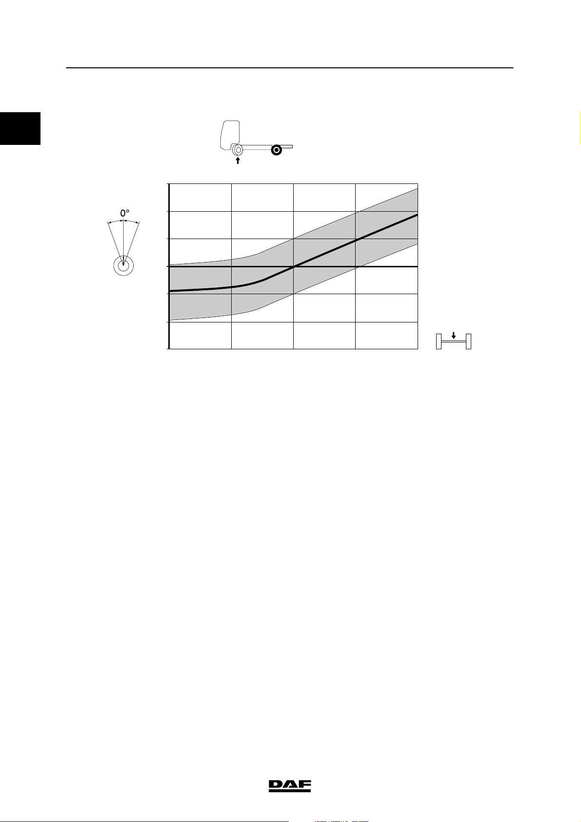
Toe
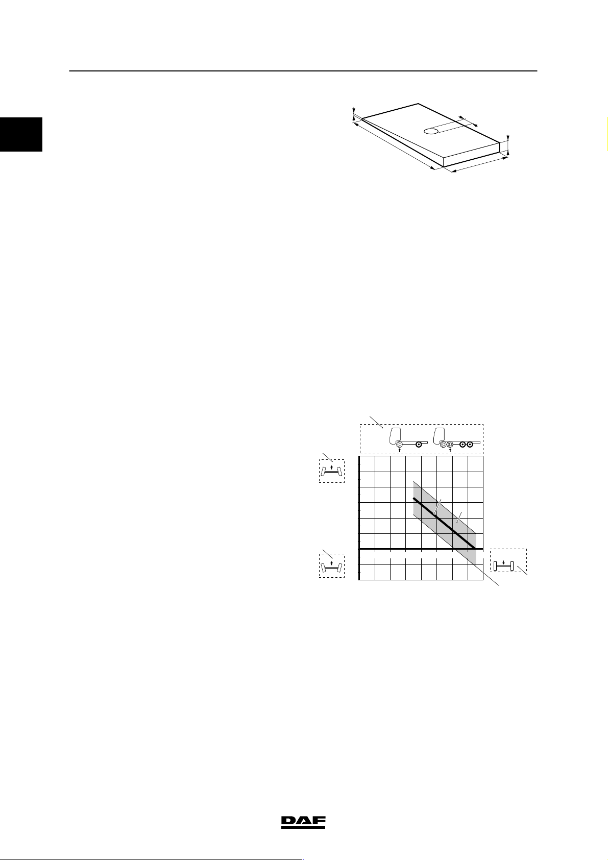
Toe values are shown in the graph.
Note:
In the graph, the toe has a value of
0.5 ᐔ 1 mm/m toe-in at 75% of the permissible
loading weight. The axle load consists of the
unloaded axle weight + loading weight.
1,5
±0,3
20,5
±0,3
±2
L
B
H
±1
S7 00 107
Explanation of graph
1. At the top of the graph, the axle type and
the axle configuration (1) is shown.
2. The toe is shown in mm/m on the left-hand
side of the graph. The values above the 0
line show toe-in values, indicated by the
symbol (2).
The values below the 0 line show toe-out
values, indicated by the symbol (3). The
toe-out values are shown as negative
values.
3. The axle load (4) is shown at the bottom of
the graph.
4. The permitted toe at any axle load is
indicated by the shaded area (5) in the
graph.
5. If the measured value lies outside the
shaded area, the toe must be adjusted to
the value indicated by the continuous
line (6).
1
mm/m
2
3
152 N
6
5,5
5
4,5
4
3,5
3
2,5
2
1,5
1
0,5
0
12345678
-0,5
-1
-1,5
-2
6
5
x 1000 KG
4
S7 00 422
6-2
ᓻ 200322
Page 25
7
TECHNICAL DATA
LF45/55 series 152N front axle
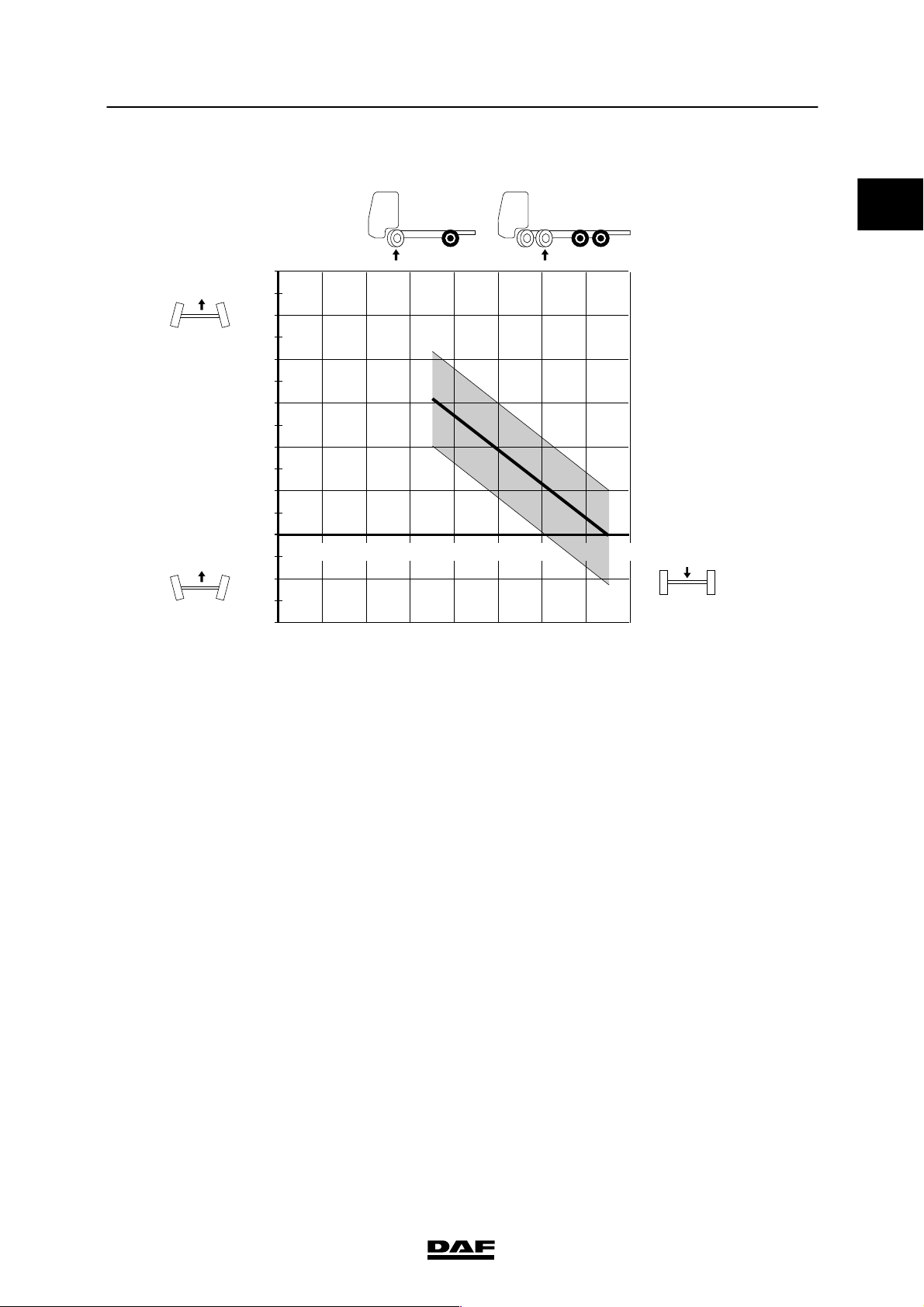
Toe, 152N front axle
0
mm/m
152 N
6
5,5
5
4,5
4
3,5
3
2,5
2
1,5
1
0,5
0
-0,5
12345678
-1
-1,5
-2
Steering ball joints
Axial play max. 1.5 mm
x 1000 KG
S7 00 414
Swivel axle
Axial play 0.05 - 0.3 mm
List of shim sizes (thickness) for adjusting
swivel axle play
1.50 mm
1.75 mm
1.88 mm
2.00 mm
2.13 mm
2.25 mm
2.38 mm
ᓻ 200322
6-3
Page 26
;
;
;
;
0
TECHNICAL DATA
7
152N front axle LF45/55 series
Wheel offset of needle bearings
- dimensiona:12-13mm
- dimensionb:3-4mm
a
b
S7 00 710
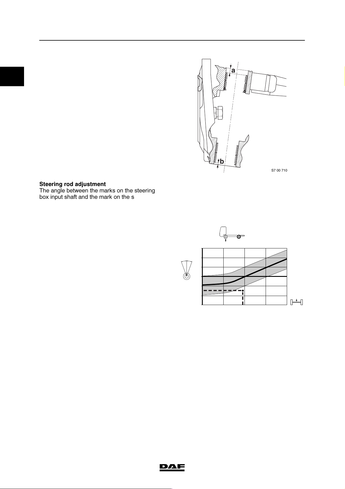
Steering rod adjustment
The angle between the marks on the steering
box input shaft and the mark on the steering box
for adjusting the steering rod are shown in the
graph. This angle is shown with the wheels of
the front axle in the “straight ahead” position.
Explanation of graph
1. The axle type and the axle configuration (1)
is shown at the top of the graph.
2. The angle between the marks on the
steering box input shaft and the mark on the
steering box (2) are shown on the left-hand
side of the graph.
Note that there are two different graphs for
LHD and RHD vehicles.
3. The front axle load (3) is shown at the
bottom of the graph.
4. The permitted angle at any axle load is
indicated by the shaded area (4) in the
graph.
5. If the measured value lies outside the
shaded area (4), the angle must be
adjusted to the value indicated by the
continuous line (5). Set the correct angle by
screwing the ball end of the steering rod in
or out.
+30
+20
0¡
+-
+10
0
-10
-20
-30
7500 7050
152 N
0,5
-9
-19
10
B
0
-10
A
5550 4150 3000
27
17
7
KG
S7 00 877
6-4
ᓻ 200322
Page 27
7
TECHNICAL DATA
LF45/55 series 152N front axle
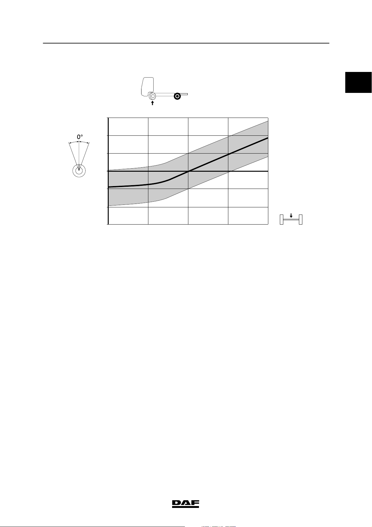
Steering rod adjustment, LHD vehicles
152 N
0
+30
+-
+20
+10
0,5
0
-9
-10
-19
-20
-30
7500 7050 5550 4150 3000
Note:
“+” on the vertical axis of the graph indicates
towards the driver’s side. “-- ” indicates towards
the co-driver’s side.
27
17
10
7
0
-10
KG
S7 00 886
ᓻ 200322
6-5
Page 28
0
TECHNICAL DATA
7
152N front axle LF45/55 series
Steering rod adjustment, RHD vehicles
152 N
+30
+20
+-
+10
0,5
0
-9
-10
-19
-20
-30
7500 7050 5550 4150 3000
Note:
“+” on the vertical axis of the graph indicates
towards the driver’s side. “-- ” indicates towards
the co-driver’s side.
27
17
10
7
0
-10
KG
S7 00 876
Steering rod arm
Abutting surface of steering rod arm to swivel
axle treated with
Wheel speed sensor ring
Axial end play max. 0.25 mm
Loctite 2701
6-6
ᓻ 200322
Page 29

7
TECHNICAL DATA
LF45/55 series 152N front axle
6.2 TIGHTENING TORQUES
The tightening torques stated in this section are
different from the standard tightening torques
included in the overview of standard tightening
torques. Any other threaded connections that
are not specified must therefore be tightened to
the tightening torque stated in the overview of
standard tightening torques.
When attachment bolts and nuts are to be
replaced, it is important - unless stated
otherwise - that these bolts and nuts are of
exactly the same length and property class as
the ones removed
.
0
ᓻ 200322
6-7
Page 30
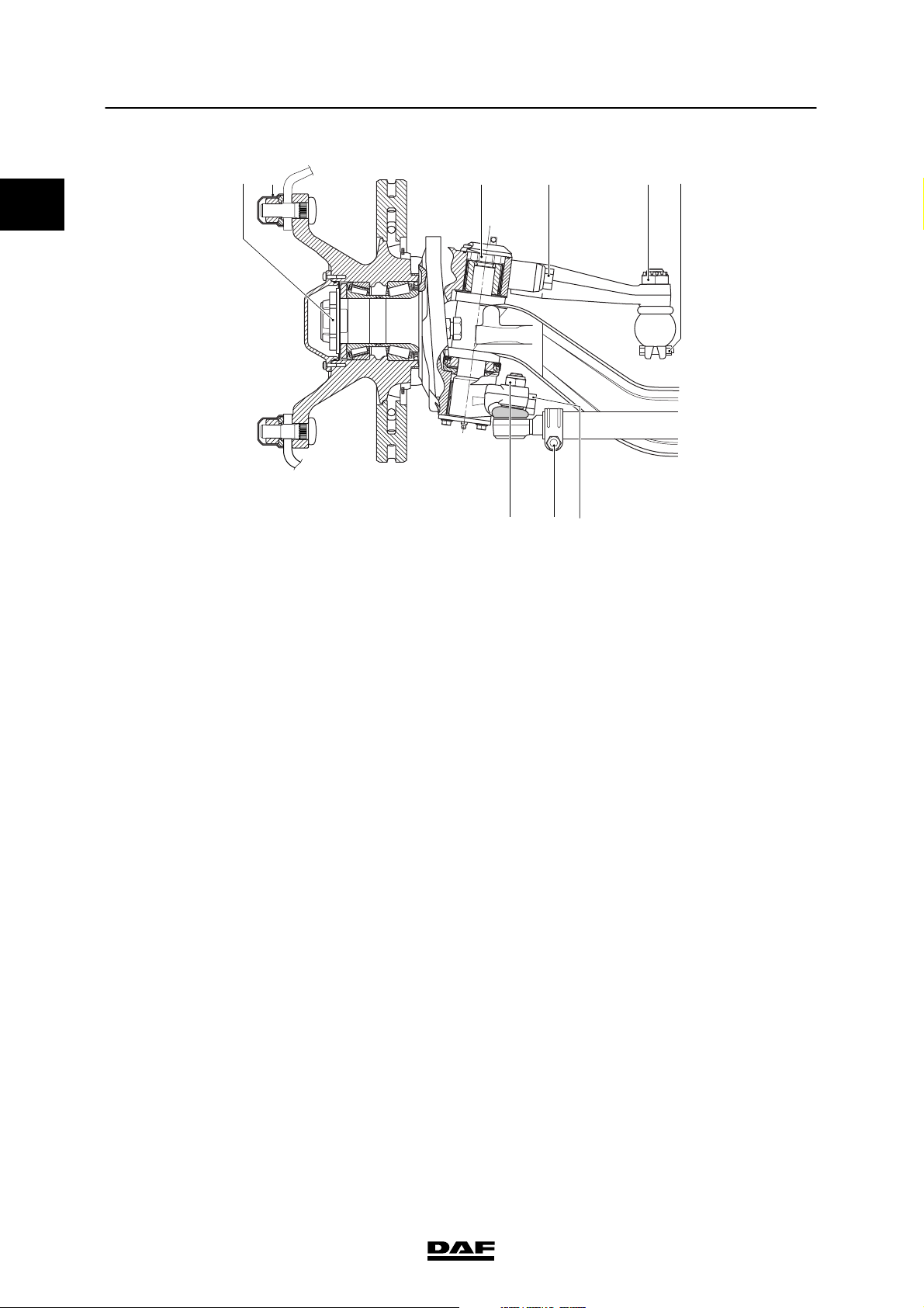
TECHNICAL DATA
7
152N front axle LF45/55 series
0
AB F
C
GH
D E
I
S7 00 883
A. Hub nut of wheel hub unit
st
-1
phase 400 Nm
-2ndphase turn the hub through 10 rotations
(1)
(2)
-3rdphase 450 Nm
th
-4
phase turn the hub through 10 rotations
(2)
-5thphase 950 Nm
B. Wheel nut 700 Nm
C. King-pin nut 595 Nm
(3)
(4)
D. Steering-rod arm attachment bolt 500 Nm + 90_ angular displacement
E. Steering rod castle nut 220 Nm
F. Attachment bolt, steering-rod clamping
bracket
90 Nm
G. M20 attachment nut, track rod 225 Nm
H. M12 attachment bolt, track rod clamping
bracket
80 Nm
(6)
(1)
(7)
(1)
I. Track rod arm attachment bolt 500 Nm + 90_ angular displacement
(5)
(5)
(1) Fit new nut.
(2) Rotate the hub at a speed of approx. 40 rpm.
(3) Retighten after 100 km. If new wheel bolts have been
fitted, the wheels need additional retightening after
500 km.
(4) Apply Loctite 243 to the nut.
(5) Fit new attachment bolt. Apply Loctite 243 to the
attachment bolt.
(6) Tighten until the split pin fits (max. 60_).
(7) Check the screw thread of the ball end for damage. Fit
new self-locking nut. Apply Loctite 243 to the nut.
6-8
ᓻ 200322
Page 31

7
TECHNICAL DATA
LF45/55 series Steered trailing swivel axle
7. STEERED TRAILING SWIVEL AXLE
7.1 GENERAL
Axle journal
Anti-corrosion agent Gleitmo 805
Wheel speed sensor
Anti-corrosion agent Molykote P37
Camber angle and kingpin inclination (KPI)
Camber angle (X) on an
unloaded axle
King-pin inclination (Y) 7_15′
0_30′
0
S7 00 129
Wheel deflection
Maximum inner wheel
deflection
Caster
Z=caster
- unloaded 3_
- loaded 5.4_
20_
Z
S7 00 835
ᓻ 200322
7-1
Page 32

0
TECHNICAL DATA
7
Steered trailing swivel axle LF45/55 series
Toe
Measured at the side walls of the tyre (B -- A)
in unloaded condition
Toe-in 0 - 1.6 mm
A
B
S7 00 833
Steering ball joints
Axial play max. 1.5 mm
King pin
Pressing force 150 kN
Steering cylinder
Length, retracted 982 ᐔ 5mm
Length, centre position 1092 ᐔ 5mm
Length, extended 1202 ᐔ 5mm
7-2
ᓻ 200322
Page 33

7
TECHNICAL DATA
LF45/55 series Steered trailing swivel axle
7.2 TIGHTENING TORQUES
The tightening torques stated in this section are
different from the standard tightening torques
included in the overview of standard tightening
torques. Any other threaded connections that
are not specified must therefore be tightened to
the tightening torque stated in the overview of
standard tightening torques.
When attachment bolts and nuts are to be
replaced, it is important - unless stated
otherwise - that these bolts and nuts are of
exactly the same length and property class as
the ones removed
.
0
ᓻ 200322
7-3
Page 34

TECHNICAL DATA
7
Steered trailing swivel axle LF45/55 series
0
A
J
I
H
A. Steering cylinder arm attachment bolt 370 ᐔ 35 Nm
B. Attachment bolt, steering cylinder
clamping bracket
C. Attachment nut, trailing axle angle sensor
control rod
D. Steering cylinder castle nut 260 ᐔ 20 Nm
E. Track rod castle nut 280 ᐔ 25 Nm
F. Track rod clamping bracket attachment
bolt
G. Track rod arm attachment bolt 420 ᐔ 40 Nm
H. Wheel nut (M20 x 1.5) 485 ᐔ 35 Nm
I. Hub nut
J. Wheel hub attachment bolt 210 ᐔ 40 Nm
st
-1
-2ndphase turn the hub through 10 rotations
-3rdphase 350 Nm
-4
-5thphase 685 ᐔ 65 Nm
phase 300 Nm
th
phase turn the hub through 10 rotations
G
45 Nm
23 Nm
80 ᐔ 10 Nm
(1)
(2)
(3)
(3)
(2)
(1)
(4)
(5)
B
C
D
E
F
S7 00 891
(6)
(6)
(1) Replace the attachment bolts and apply Loctite 243.
(2) Fit new self-locking nut.
(3) Tighten until the split pin fits (max. 60_).
(4) Retighten after 100 km. If new wheel bolts have been
fitted, the wheels need additional retightening after
500 km.
(5) Fit new hub nut.
(6) Rotate the hub at a speed of approx. 40 rpm.
7-4
ᓻ 200322
Page 35

7
LF45/55 series Contents
DIAGNOSTICS
CONTENTS
Page Date
1. STEERING GEAR, GENERAL 1-1 200322........................................... ....
1.1 Fault-finding table 1-1 200322................................................. ....
1
ᓻ 200322
1
Page 36

1
7DIAGNOSTICS
Contents LF45/55 series
2
ᓻ 200322
Page 37

7
DIAGNOSTICS
LF45/55 series Steering gear, general
1. STEERING GEAR, GENERAL
1.1 FAULT-FINDING TABLE
SYMPTOM: HEAVY STEERING, TO BOTH SIDES
Possible cause Remedy
Tyre pressure of steerable wheels too low. Check the tyre pressure. Increase tyre pressure
to the specified value.
Semi-trailer coupling damaged or insufficiently
lubricated.
Axle load of steerable axle(s) too high. Check axle load.
Steering oil level too low. Check steering oil level.
Air in the system. Bleed the system.
Filter is extremely dirty. Check filter. Replace the filter, if necessary.
Steering oil pipe kinked or pinched off. Check routing of the steering oil pipes.
The intake opening in the reservoir is (partially)
blocked.
Tight steering column bearings or universal
joint(s).
Tight swivel axle bearing. Check steerable axle(s).
Excessive caster. Check caster. Reduce if necessary.
Inspect/lubricate semi-trailer coupling.
Adjust the load.
Top up oil and bleed system.
Check system for leaks.
Check steering oil for foaming.
Check intake opening in the reservoir.
Jack up front axle and check the steering column
tightening torque.
1
System pressure too low. Check maximum system pressure.
Replace pressure-limiting valve or steering
pump.
Steering pump output too low. Check pump output.
Check whether the flow-control valve is jammed.
Replace steering pump, if necessary.
Excessive internal steering box leakage Check for internal leaks in steering box.
ᓻ 200322
1-1
Page 38

DIAGNOSTICS
7
Steering gear, general LF45/55 series
SYMPTOM: HEAVY STEERING, TO ONE SIDE
Possible cause Remedy
1
Faulty two-way valve, on a vehicle with steered
trailing swivel axle.
Dirty high-pressure filter, on a vehicle with
steered trailing swivel axle.
Tyre pressure of steerable wheels too low. Check the tyre pressure. Increase tyre pressure
Semi-trailer coupling damaged or insufficiently
lubricated.
Steering oil level too low. Check steering oil level.
Air in the system. Bleed the system.
Wheel-deflection limiting valves set incorrectly. Check setting of the wheel deflection limiting
Tight swivel axle bearing. Check steerable axle(s).
Misalignment of the steering column universal
joints.
Excessive internal steering box leakage on one
side.
Check operation of two-way valve.
Check high-pressure filter. Replace the filter, if
necessary.
to the specified value.
Inspect/lubricate semi-trailer coupling.
Top up oil and bleed system.
Check system for leaks.
Check steering oil for foaming.
valves.
Check/adjust position of the universal joints in
relation to each other.
Check for internal leaks in steering box.
1-2
ᓻ 200322
Page 39

7
DIAGNOSTICS
LF45/55 series Steering gear, general
SYMPTOM: HEAVY STEERING, OCCASIONALLY
Possible cause Remedy
Semi-trailer coupling damaged or insufficiently
lubricated.
Steering oil level too low. Check steering oil level.
Air in the system. Bleed the system.
The steering oil pipe is temporarily kinked or
pinched off.
The intake opening in the reservoir is temporarily
blocked.
Steering pump output too low because
flow-control valve is jammed.
Low steering-pump output in “cold condition” and
at low engine speed because the partitions jam in
the rotor.
Excessive internal steering box leakage at lower
pressures.
Faulty two-way valve, on a vehicle with steered
trailing swivel axle.
Inspect/lubricate semi-trailer coupling.
Top up oil and bleed system.
Check system for leaks.
Check steering oil for foaming.
Check routing of the steering oil pipes.
Check reservoir for impurities.
Check the flow-control valve for smooth
operation.
Check pump output when steering pump is
“cold”.
Replace steering pump.
Check internal steering box leakage at a set
pressure of 15-30 bar.
Check operation of the two-way valve.
1
ᓻ 200322
1-3
Page 40

DIAGNOSTICS
7
Steering gear, general LF45/55 series
SYMPTOM: WHEEL DEFLECTION TOO SMALL
Possible cause Remedy
The vehicle is being steered when at a standstill. Steer while the vehicle is moving.
1
Incorrect setting of maximum wheel deflection on
the axle.
Wheel deflection limiting valves incorrectly
adjusted.
Axle load of steerable axle(s) too high. Check the axle load(s).
System pressure too low. Check maximum system pressure.
Steering rod adjusted incorrectly. Check steering rod setting.
Pitman arm installed in the wrong position on
steering box output shaft.
Sector shaft is installed in the wrong position in
the steering box.
Check maximum wheel deflection and, if
adjusted incorrectly, correct.
Check setting of the wheel deflection limiting
valves.
Adjust the load.
Replace pressure-limiting valve or steering
pump.
Check whether position of pitman arm on the
sector shaft is correct, using the marks.
Put steering box in the central position and check
whether the sector shaft is correctly installed,
using the marks on the input shaft and on the
sector shaft.
1-4
ᓻ 200322
Page 41

7
DIAGNOSTICS
LF45/55 series Steering gear, general
SYMPTOM: VEHICLE PULLS TO ONE SIDE
Possible cause Remedy
Uneven weight distribution causing the vehicle to
tilt.
Semi-trailer coupling insufficiently lubricated. Lubricate semi-trailer coupling.
Driving over cambered roads. When driving over cambered roads, bear in mind
Difference in tyre pressure between the wheels
on the steerable axle(s).
Different tyre types or difference in tread depth
between tyres of the steerable axle(s).
Different wheel rims installed on the steerable
axle(s).
Fault in one of the tyres. Replace the tyre on the side to which the vehicle
Steerable axle brake(s) continue to “hang”. Check brakes. Carry out any repairs.
Misalignment of the steering column universal
joints.
Excessive wheel bearing play. Check the wheel bearings for play. Replace the
Incorrect caster. Check caster. Set correct caster.
Incorrect camber angle. Check camber angle.
Adjust the weight distribution.
that the vehicle might pull to one side.
Check the tyre pressure. Pump both tyres up to
the specified value.
Always fit tyres of the same type and tread depth
on the axle.
Always install wheel rims of the same type on the
axle.
pulls.
Check/adjust position of the universal joints in
relation to each other.
wheel bearings if necessary.
Check axle housing.
1
Incorrect alignment of steerable axle(s). Check alignment of the steerable axle(s.) Adjust
steering rod correctly.
Alignment/calibration of steered trailing swivel
axle incorrect.
Alignment of rear axle(s) or of trailer/semi-trailer
incorrect.
Check alignment/calibration of steered trailing
swivel axle.
Correct alignment/calibration.
Check alignment of the rear axle(s) or of
trailer/semi-trailer. Align axles.
ᓻ 200322
1-5
Page 42

DIAGNOSTICS
7
Steering gear, general LF45/55 series
SYMPTOM: VEHICLE PULLS TO ONE SIDE
Possible cause Remedy
Front-axle/rear-axle suspension play. Check suspension. Replace worn parts.
1
Difference in spring opening between the leaf
springs of one axle
Incorrect setting of air suspension. This will
cause the vehicle to tilt.
Steering-pump output too high. Check pump output.
Incorrect hydraulic central position of the steering
box.
Measure the spring opening of the springs.
Replace springs.
Check height adjustment. Set the height control
correctly.
Check the flow-control valve for smooth
operation.
Check the hydraulic central position of the
steering box.
The hydraulic central position cannot be
adjusted.
Replace the steering box.
1-6
ᓻ 200322
Page 43

7
DIAGNOSTICS
LF45/55 series Steering gear, general
SYMPTOM: VEHICLE IS SEARCHING, TRACKING INSTABILITY
Possible cause Remedy
Tyre pressure of steerable wheels too low. Check the tyre pressure.
Increase tyre pressure to the specified value.
Semi-trailer coupling insufficiently lubricated or
damaged.
Incorrect steering-box pressure-point setting;
play at the pressure point or pressure point set
too tight.
Axle load on front axle too low. Check axle load and adjust the load.
Incorrect toe-in. Check toe-in.
Incorrect caster. Check caster.
Alignment/calibration of steered trailing swivel
axle incorrect.
Play in a universal joint or in the steering column
sliding joint. Tight universal joint.
Misalignment of the universal joints in the
steering column.
Play in the steering-rod ball joints Check ball joints.
Steering box, steering bracket or steering rod
attachment loose.
Inspect/lubricate semi-trailer coupling.
Check pressure point setting. Set correct
pressure point.
Set correct toe-in.
Set correct caster.
Check alignment/calibration of steered trailing
swivel axle.
Correct alignment/calibration.
Check universal joints and the steering column
sliding joint. Replace worn parts.
Check/adjust position of the universal joints in
relation to each other.
Replace ball joint.
Check attachments, retighten bolts/nuts.
1
Worn or tight swivel axle bearing. Check swivel axle bearing.
Replace worn parts.
Incorrect steering-rod adjustment; when the
wheels are in the “straight ahead” position, the
steering box is not in its mechanical central
position (pressure point).
Front-axle and/or rear-axle suspension play. Check axle suspension. Replace worn parts.
Check steering rod setting.
Adjust steering rod correctly.
ᓻ 200322
1-7
Page 44

1
DIAGNOSTICS
Steering gear, general LF45/55 series
SYMPTOM: VEHICLE IS SEARCHING, TRACKING INSTABILITY
Possible cause Remedy
Steering pump output too high. Check steering pump output.
Check the flow-control valve for smooth
operation.
Replace steering pump, if necessary.
Excessive internal steering box resistance. Check internal steering box resistance.
Replace steering box.
Internal defect in the steering box. Replace steering box.
7
1-8
ᓻ 200322
Page 45

7
DIAGNOSTICS
LF45/55 series Steering gear, general
SYMPTOM: STEERING WHEEL DOES NOT RETURN TO THE “STRAIGHT AHEAD” POSITION
(OR ONLY VERY SLOWLY)
Possible cause Remedy
Tyre pressure of steerable wheels too low. Check the tyre pressure.
Increase tyre pressure to the specified value.
Semi-trailer coupling insufficiently lubricated or
damaged.
Inspect/lubricate semi-trailer coupling.
1
Misalignment of the steering column universal
joints.
Axle load on front axle too low. Check axle load and adjust the load.
Incorrect caster. Check caster.
Tight universal joint or steering column bearing. Check universal joints and steering column
Friction between mechanical parts of the steering
gear (pitman arm, steering rod/steering arm or
track rod/track rod arm).
Steering box or steering bracket loose. Check attachments, retighten bolts.
Tight swivel axle bearing. Check swivel axle bearing.
Steering pump output too high. Check pump output.
Pressure point set too tight. Check pressure point setting. Adjust pressure
Excessive internal steering box resistance. Check internal steering box resistance.
Internal defect in the steering box. Replace steering box.
Check/adjust position of the universal joints in
relation to each other.
Set correct caster.
bearing. Replace worn parts.
Check mechanical parts of the steering gear.
Check the flow-control valve for smooth
operation.
Replace pump.
point correctly.
Replace steering box.
ᓻ 200322
1-9
Page 46

1
DIAGNOSTICS
7
Steering gear, general LF45/55 series
SYMPTOM: JOLTING OF THE STEERING WHEEL
Possible cause Remedy
Air in the system. Check steering oil level and bleed system.
Worn or loose shock absorbers on the front axle. Check the attachment.
Replace shock absorbers.
Steering pump output too low. Check steering pump output.
Loose steering rod, track rod, steering bracket or
steering box.
Excessive internal steering box play. Check the input shaft play.
SYMPTOM: VIBRATIONS IN THE STEERING WHEEL
Possible cause Remedy
Dirt between wheel rim and hub. Remove wheel and clean wheel rim and hub.
Wheel studs unevenly tightened. Loosen all nuts and tighten these as specified.
Wheel imbalance. Balance wheel statically and dynamically.
SYMPTOM: AIR IN THE STEERING OIL
Possible cause Remedy
Reservoir oil level too low. Check the oil level.
Internal steering pump seals are poor. Replace steering pump.
Check/tighten attachment of these components.
Check the steering box pressure point.
Replace the steering box.
Install wheel in the specified manner.
Topupoil.
Check for leaks.
1-10
ᓻ 200322
Page 47

7
DIAGNOSTICS
LF45/55 series Steering gear, general
SYMPTOM: STEERING OIL LEAKAGE
Possible cause Remedy
Leaking delivery or return pipe.
Leaking delivery or return-pipe connection.
Reservoir or reservoir/steering pump seal
leaking.
Leaking steering pump. Check the steering pump for leaks.
Leaking steering box. On the steering box, check the following seals:
The melting point of the grease behind the dust
seal of the sector shaft or the input shaft is too
low.
There appears to be a leak in the steering box,
but in fact the grease has melted.
Check the pipes and pipe connections.
Tighten pipes securely.
Replace the reservoir or repair the
reservoir/steering pump seal.
- input shaft oil seal
- cover O-ring on underside of steering box
- pressure-limiting valve O-ring
- wheel-deflection limiting valve stop bolts
- various plugs and connection nipples
Depending on the leak, replace the input shaft oil
seal, the O-ring of the cover on the underside of
the steering box, the pressure-limiting valve
O-ring, the stop bolt and wheel-deflection limiting
valve sealing rings and the seals of the various
plugs and connection nipples.
Replace the steering box in the case of leaks
other than those described above.
Replace the grease with grease of the specified
type (melting point >130_C.
1
ᓻ 200322
1-11
Page 48

1
DIAGNOSTICS
7
Steering gear, general LF45/55 series
NOISE
Note:
The steering gear always produces noise.
Normal noise:
- a hissing noise in the steering box while
steering. The noise level depends on the
system pressure.
- an increasing sound level when the
wheel-deflection limiting valve is opened.
- a maximum sound level when the
pressure-limiting valve is opened.
SYMPTOM: STEERING PUMP PRODUCES A SQUEALING NOISE WHILE STEERING
Possible cause Remedy
Oil level too low, causing the steering pump to
draw air.
Air in the steering oil. Check oil for the presence of air (foaming).
The intake opening in the reservoir is (partially)
blocked.
SYMPTOM: THE STEERING PUMP PRODUCES A DIFFERENT NOISE WHEN AT IDLING SPEED.
THE NOISE LEVEL INCREASES WHEN THE ENGINE SPEED INCREASES
Possible cause Remedy
Worn steering pump. Replace steering pump.
Check the oil level.
Top up oil and check for leaks.
Bleed system and trace the cause.
Check intake opening in the reservoir.
Replace steering oil.
Clean the reservoir and pipes.
Replace filter.
1-12
ᓻ 200322
Page 49

7
DIAGNOSTICS
LF45/55 series Steering gear, general
SYMPTOM: WHEN STEERING THE SOUND OF METAL SCRAPING AGAINST METAL IS HEARD
Possible cause Remedy
Loose steering box, steering bracket or pitman
arm.
Play in a steering-rod or track-rod ball joint. Check ball joints.
There is friction between steering gear
components.
Play in the steering column sliding joint. Check sliding joint for wear.
Check attachment of components.
Tighten bolts to the specified tightening torque.
Replace ball joint.
Turn steering gear carefully from one stop to the
other and check the mechanical part of the
steering gear for friction.
Replace sliding joint.
1
ᓻ 200322
1-13
Page 50

1
DIAGNOSTICS
Steering gear, general LF45/55 series
7
1-14
ᓻ 200322
Page 51

7
STEERING GEAR, GENERAL
LF45/55 series Contents
CONTENTS
Page Date
1. SAFETY INSTRUCTIONS 1-1 200322............................................... ....
2. GENERAL 2-1 200322............................................................ ....
2.1 Overview drawing of steering gear,
version without steered trailing swivel axle 2-1 200322........................... ....
2.2 Overview drawing of steering gear,
version with steered trailing swivel axle 2-2 200322.............................. ....
2.3 System description of steering gear,
version without steered trailing swivel axle 2-3 200322........................... ....
2.4 System description of steering gear,
version with steered trailing swivel axle 2-5 200322.............................. ....
3. INSPECTION AND ADJUSTMENT 3-1 200322....................................... ....
3.1 Inspecting the steering gear using a pressure gauge 3-1 200322................... ....
3.2 Inspecting steering gear using the test case 3-4 200322.......................... ....
3.3 Checking the steering box attachment 3-12 200322............................... ...
3.4 Checking hydraulic centre position 3-12 200322.................................. ...
4. DRAINING, FILLING AND BLEEDING 4-1 200322................................... ....
4.1 Draining, filling and bleeding steering gear,
version without steered trailing swivel axle 4-1 200322........................... ....
4.2 Draining, filling and bleeding steering gear,
version with steered trailing swivel axle 4-4 200322.............................. ....
2
ᓻ 200322
1
Page 52

2
7STEERING GEAR, GENERAL
Contents LF45/55 series
2
ᓻ 200322
Page 53

7
STEERING GEAR, GENERAL
LF45/55 series Safety instructions
1. SAFETY INSTRUCTIONS
The steering gear is one of the most important
systems on the vehicle in terms of safety. This
should be borne in mind at all times when
carrying out maintenance and repair work on the
steering gear. Always work in a very clean
environment; even the smallest amount of dirt in
the system can cause faults.
Repair and maintenance work on the steering
gear should only be carried out by experienced
mechanics with the appropriate training.
If the vehicle is fitted with an airbag,
observe the warnings and safety
instructions applicable to working
on an airbag system.
Tighten all joints to the specified torque, see
“Technical data”.
Always check pipe connections for leaks after
tightening.
2
If the vehicle has been involved in a collision, in
which the steering box or other steering gear
components (may) have been damaged, the
steering box must always be sent to DAF for
inspection or be replaced. This requirement still
applies even if no external damage is visible.
The steering box may have sustained internal
damage in the collision, causing it to be
unreliable.
The other steering gear components, which
could have been damaged, such as the steering
and track rods, steering and track-rod arms,
steering bracket, pitman arm and the
attachments of these components must always
be checked for distortions, cracks, fractures, etc.
If possible, all components should be magnaflux
tested.
Damaged components must always be
replaced. If in doubt, always replace the
component.
ᓻ 200322
1-1
Page 54

2
STEERING GEAR, GENERAL
7
Safety instructions LF45/55 series
Always use original DAF components when
replacing components.
Do not take risks. Replace components if in
doubt.
Welding of steering-mechanism components is
prohibited.
Straightening of steering gear components is
prohibited.
An incorrect pressure point setting will affect the
vehicle’s steering characteristics.
Check the thread of the ball end for damage
before fitting a new castle nut or self-locking nut
to the ball end.
Screwing a new castle nut or
self-locking nut onto a ball end with
a damaged screw thread can give
rise to dangerous situations.
Always take a test drive after completing
maintenance or repair work on the steering gear.
Be aware during this test drive that the steering
gear may not function properly.
1-2
ᓻ 200322
Page 55

7
LF45/55 series General
STEERING GEAR, GENERAL
2. GENERAL
2.1 OVERVIEW DRAWING OF STEERING GEAR, VERSION WITHOUT STEERED
TRAILING SWIVEL AXLE
3 4
1
2
2
1. Reservoir
2. Steering pump
3. Delivery pipe
4. Steering box
5. Return pipe
5
S7 00 536
ᓻ 200322
2-1
Page 56

2
STEERING GEAR, GENERAL
General LF45/55 series
2.2 OVERVIEW DRAWING OF STEERING GEAR, VERSION WITH STEERED
TRAILING SWIVEL AXLE
1
2
7
4
5
1. Reservoir
2. Steering pump
3. High-pressure filter
4. Distribution block
5. Steering box with angle sensor
6. RAS-EC steering gear
3
RAS-EC
6
S7 00 836
2-2
ᓻ 200322
Page 57

7
STEERING GEAR, GENERAL
LF45/55 series General
2.3 SYSTEM DESCRIPTION OF STEERING GEAR, VERSION WITHOUT
STEERED TRAILING SWIVEL AXLE
3 4
1
2
2
The oil flows to the steering pump (2) from the
reservoir (1) mounted on the steering pump (2).
There is a filter in the reservoir (1). The filter and
reservoir form part of a single unit. At maximum
pump output, the oil is pumped to the reservoir
with approx.
approx.
reservoir (1).
The steering pump is a non-regenerative vane
pump. Once the pump starts supplying oil, the
steering pump (2) will continue to draw oil by
itself.
The steering pump (2) pumps the oil through the
delivery pipe (3) to the steering box (4).
1
/3passing through the filter (2) and
2
/3of the oil pumped directly to the
5
S7 00 536
ᓻ 200322
2-3
Page 58

2
STEERING GEAR, GENERAL
7
General LF45/55 series
From the steering box (4), the oil is returned to
the reservoir (1) through the return pipe (5). The
pressure in the return pipe is always low.
The pressure in the delivery pipe (3) varies and
depends on the steering force. If there is no
steering action, the oil in the delivery pipe is at
circulation pressure.
If a steering action takes place, the pressure in
the delivery pipe (3) can increase to the preset
value of the pressure-limiting valve.
This maximum pressure may occur when the
vehicle is steered while at a standstill on a
skid-resistant road surface or when the vehicle
is parked against a curb and the steering wheel
is turned.
When at maximum pressure a major
transmission of energy will take place, resulting
in the release of much heat. If this situation lasts
too long, the steering pump can be damaged by
the heat development.
The steering pump is capable of generating a
very high pressure over a short period
(depending on the pump type up to approx.
300 bar). This very high pressure can cause
certain steering-mechanism components to
become overloaded or even to break off.
The pressure-limiting valve protects the steering
mechanism from excessive pressures.
Increasing the system pressure is not permitted.
The pressure-limiting valve is located in the
steering box. This can be checked using the
type plate on the steering box. If a pressure
value is stated on the type plate, the component
concerned contains a pressure-limiting valve.
It can be very dangerous to replace
the steering box or the steering
pump with a different type of
steering box or pump. Therefore,
replacing these components
without DAF’s express permission
is prohibited. If the original type is
no longer available, DAF will supply
another approved type.
2-4
ᓻ 200322
Page 59

7
LF45/55 series General
2.4 SYSTEM DESCRIPTION OF STEERING GEAR, VERSION WITH STEERED
TRAILING SWIVEL AXLE
STEERING GEAR, GENERAL
1
2
2
3
4
5
The oil flows to the steering pump (2) from the
reservoir (1).
There is a filter element in the reservoir. The
filter element is fitted in the return pipe.
RAS-EC
6
S7 00 836
ᓻ 200322
2-5
Page 60

2
STEERING GEAR, GENERAL
7
General LF45/55 series
The steering pump (2) is a non-regenerative
vane pump. Once the pump starts supplying oil,
the steering pump will continue to draw oil itself.
The steering pump pumps the oil through the
delivery pipe to the high-pressure filter (3).
The steering oil is pumped from the
high-pressure filter to the distribution block (4).
The flow of oil is divided into two equal parts in
the distribution block: one for the front axle
steering gear and one for the rear axle steering
gear.
From the steering box (5), the oil is returned to
the reservoir (1) through the return pipe. The
pressure in the return pipe is always low.
The pressure in the delivery pipe varies and
depends on the steering force. If there is no
steering action, the oil in the delivery pipe is at
circulation pressure.
If a steering action takes place, the pressure in
the delivery pipe can increase to the preset
value of the pressure-limiting valve.
This maximum pressure can occur when the
vehicle is steered while at a standstill on a
skid-resistant road surface or when the vehicle
is parked against a curb and the steering wheel
is turned.
When at maximum pressure a major
transmission of energy will take place, resulting
in the release of much heat. If this situation lasts
too long, the steering pump can be damaged by
the heat development.
The steering pump is capable of generating a
very high pressure over a short period
(depending on the pump type up to approx.
300 bar). This very high pressure can cause
certain steering-mechanism components to
become overloaded or even to break off.
2-6
ᓻ 200322
Page 61

7
STEERING GEAR, GENERAL
LF45/55 series General
The pressure-limiting valve protects the steering
mechanism from excessive pressures.
Increasing the system pressure is not permitted.
The pressure-limiting valve is located in the
steering box. This can be checked using the
type plate on the steering box. If a pressure
value is stated on the type plate, the component
concerned contains a pressur-limiting valve.
It can be very dangerous to replace
the steering box or the steering
pump with a different type of
steering box or pump. Therefore,
replacing these components
without DAF’s express permission
is prohibited. If the original type is
no longer available, DAF will supply
another approved type.
2
ᓻ 200322
2-7
Page 62

2
STEERING GEAR, GENERAL
General LF45/55 series
7
2-8
ᓻ 200322
Page 63

7
STEERING GEAR, GENERAL
LF45/55 series Inspection and adjustment
3. INSPECTION AND ADJUSTMENT
3.1 INSPECTING THE STEERING GEAR USING A PRESSURE GAUGE
Note:
A quick check of the steering gear can be
carried out using a pressure gauge. The gauge
used for checking the final limiting pressure can
be used for this purpose.
Only a limited number of measurements can be
carried out using a pressure gauge. A test
equipment case is required to test the steering
pump (output in l/min. at a specific pressure)
and the condition of the steering-box (internal
sealing, play).
If the cause of the problem cannot be traced
with the pressure gauge, the problem on the
steering gear should be diagnosed using the
test case.
Always check the tightening torque
of the steering wheel bolt after the
steering wheel has been turned
using a torque wrench.
2
Points for attention when connecting the
pressure gauge:
1. Clean the delivery pipe connections that are
going to be disconnected.
2. Check the steering box attachment.
3. Check the hydraulic central position.
4. Place proper turning plates under the
vehicle’s steerable wheels.
Block the vehicle so that it cannot
slide off the jack or the turning
plates.
ᓻ 200322
3-1
Page 64

2
STEERING GEAR, GENERAL
7
Inspection and adjustment LF45/55 series
Connecting pressure gauge
Only use couplings and pipes which
are suitable for the maximum
system pressure.
1. Connect the pressure gauge, using the
special tool (DAF no. 0535653) to the
T-piece in the delivery pipe. Make sure that
as little steering oil as possible escapes and
clear away spilt oil.
2. Check the steering oil level and top up as
necessary.
3. Bleed the steering gear, see “Draining,
filling and bleeding”.
Bringing the steering oil up to the test
temperature
1. Set the engine speed to 1200 - 1400 rpm.
2. Activate the steering gear for 5 seconds at
its maximum, making sure that the pressure
does not exceed 50 bar. Do not touch the
steering wheel for 5 seconds.
3. Repeat this procedure until the pipes are
warm to the touch, at least.
Measuring the circulation pressure
1. Run the engine at idling speed.
2. Check the circulation pressure. Compare
the reading with the specified value, see
“Technical data”.
Checking front axle bearings
1. Run the engine at idling speed.
2. Turn the steering wheel evenly from the
central position to both maximum wheel
deflections.
3. Check whether the pressure rises evenly.
S7 00 614
3-2
ᓻ 200322
Page 65

7
STEERING GEAR, GENERAL
LF45/55 series Inspection and adjustment
Testing the maximum system pressure.
1. Run the engine at idling speed.
2. Activate the steering gear and fit a 15 mm
filler piece, special tool (DAF no. 0535996),
between the adjusting bolt or the axle stop
on the swivel axle and axle-housing stop.
Be careful when fitting the 15 mm
filler piece between the adjusting
boltandtheaxlestop,asthereisa
danger of limbs getting trapped.
S7 00 598
2
3. Fit a torque wrench with a dial to the
steering wheel attachment bolt. Tighten the
bolt to a tightening torque of 45 Nm on the
torque wrench.
4. Take the maximum pressure reading on the
pressure gauge (the maximum pressure
should not be held for more than 5
seconds). Compare the reading with the
specified value, see “Technical data”.
Note:
If the reading deviates more than 10% from
the specified value, the cause should be
identified using the test case.
5. Repeat the measurement using the 15 mm
filler piece at the other end of the front axle.
6. Retighten the steering-wheel attachment
bolt to the specified tightening torque, see
“Technical data”.
7. Remove the pressure gauge and the
T-piece.
8. Check the steering oil level in the reservoir
and top up if necessary.
45Nm
45Nm
S7 00 611
9. Bleed the steering gear, see “Draining,
filling and bleeding”.
ᓻ 200322
3-3
Page 66

2
STEERING GEAR, GENERAL
7
Inspection and adjustment LF45/55 series
3.2 INSPECTING STEERING GEAR USING THE TEST CASE
Note:
Thetestcaseisusedto:
- inspect the condition of the entire steering
gear on a regular basis;
- make a reliable diagnosis if the steering
gear does not function properly.
Inspection using a pressure gauge will only
provide information on system pressures, which
in some cases might be insufficient to trace the
fault. However, this provides no information on
the condition of the steering pump (output) and
the steering box (internal leaks). This often
results, in practice, in steering pumps and
steering boxes being replaced unnecessarily.
Electronic test equipment case
“Servotest 550”
The inspection referred to below is carried out
using the “Servotest 550” test equipment case. It
is also possible to inspect the steering gear
using similar equipment that can be used to
carry out the same measurements as the
“Servotest 550”.
The test case is connected to the delivery pipe,
which runs from the steering pump to the
steering box.
The “Eingang” (input) pipe connection is fitted
with a filter, which should be cleaned regularly,
depending on the amount of dirt in the oil.
Always check the tightening torque
of the steering wheel bolt after the
steering wheel has been turned
using a torque wrench.
3-4
ᓻ 200322
Page 67

7
STEERING GEAR, GENERAL
LF45/55 series Inspection and adjustment
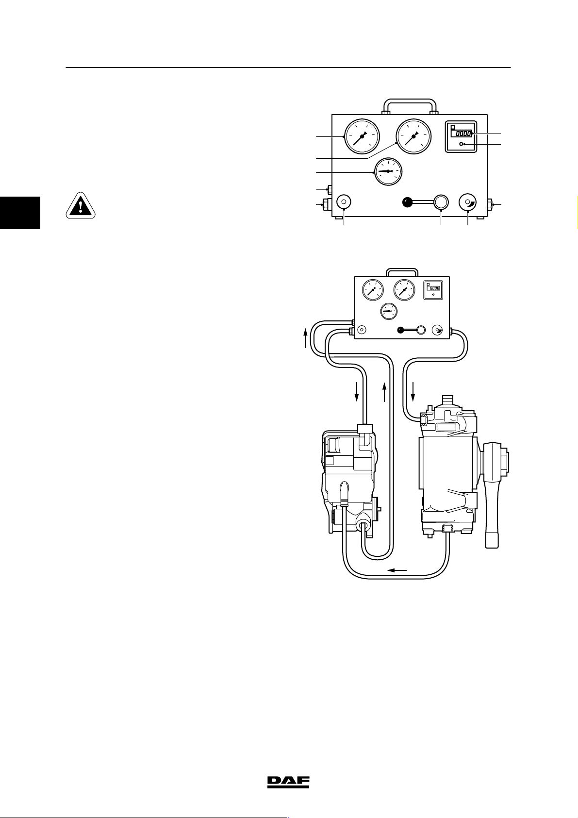
The “Servotest 550” test equipment case
consists of the following parts:
1. “Eingang” (input) connection
2. “Ausgang” (output) connection
3. “Tank” connection
4. Valve
5. Non-return valve (throttle)
6. Pressure-limiting valve 120/150 bar (switch
over)
7. Output meter 0.01 - 100 l/min.
8. Switch for output meter
9. Low-pressure pressure gauge0-25bar
10. High-pressure pressure gauge 0 - 250 bar
11. Temperature gauge0-120_C.
Points for attention when connecting the test
case:
1. Clean the delivery pipe connections that are
going to be disconnected.
2. Check the steering box attachment.
9
10
11
1
3
5
10 15
20
25
100 150
50
200
250
465
S7 00 020
7
8
2
2
3. Check the hydraulic central position.
4. Place proper turning plates under the
vehicle’s steerable wheels.
Block the vehicle so that it cannot
slide off the jack or the turning
plates.
S7 00 610
ᓻ 200322
3-5
Page 68
2
STEERING GEAR, GENERAL
7
Inspection and adjustment LF45/55 series
Connecting the test case
1. Check whether the non-return valve (5) of
the “Servotest 550” is completely closed,
the valve (4) has been fully opened and the
pressure adjusting device (6) of the
pressure-limiting valve is set in accordance
with the maximum steering system
pressure.
Only use couplings and pipes that
are suitable for the maximum
9
10
11
1
3
5
10 15
20
25
100 150
50
200
250
system pressure.
465
2. Connect the test case to the delivery pipe.
Make sure that as little steering oil as
possible escapes and clear away spilt oil.
Connect the pipe from the “Eingang”
connection of the test equipment case to
the part of the pipe from the steering pump.
Connect the pipe from the “Ausgang”
connection of the test equipment case to
the part of the pipe going to the steering
box.
10 15
5
100 150
50
20
25
200
250
S7 00 020
7
8
2
Note:
In the case of vehicles with a steered
trailing swivel axle, connect the test case in
the delivery pipe downstream of the
two-way valve.
3. Place the hose from the “Tank” connection
in the reservoir. Connect this hose securely
to the reservoir. Ensure that the end of the
hose remains below the surface of the oil to
prevent foaming.
4. Check the steering oil level and top up as
necessary.
5. Start the engine and keep an eye on the
steering oil level.
6. Bleed the steering gear, see “Draining,
filling and bleeding”.
S7 00 535
3-6
ᓻ 200322
Page 69

7
STEERING GEAR, GENERAL
LF45/55 series Inspection and adjustment
Bringing the steering oil up to the test
temperature
1. Set the engine speed to 1200 - 1400 rpm.
2. Slowly close the valve (4), until the pressure
gauge (10) indicates a pressure of 50 bar.
3. Wait until the temperature gauge (11)
indicates a value of 50_C.
4. Now open the valve (4) completely.
Inspecting steering gear using the test case
9
10
11
5
10 15
20
25
100 150
50
200
250
1
Note:
- Check the steering oil temperature regularly
while taking measurements. Warm up the
steering oil as specified.
- If an incorrect value is found during the
measurements, the cause should be traced
and rectified before carrying out the next
measurement.
Measuring the circulation pressure
1. Run the engine at idling speed.
3
465
S7 00 020
7
8
2
2
2. Open the valve (4) fully.
3. The circulation pressure is indicated on the
pressure gauge (9). Compare the reading
with the maximum permitted value, see
“Technical data”.
Checking front axle bearings
1. Run the engine at idling speed.
2. Check whether the valve (4) is fully opened.
3. Turn the steering wheel carefully from the
central position to both maximum wheel
deflections.
4. Check whether the required pressure rises
evenly.
9
10
11
1
3
5
10 15
100 150
50
20
25
200
250
7
8
2
465
S7 00 020
ᓻ 200322
3-7
Page 70
2
STEERING GEAR, GENERAL
7
Inspection and adjustment LF45/55 series
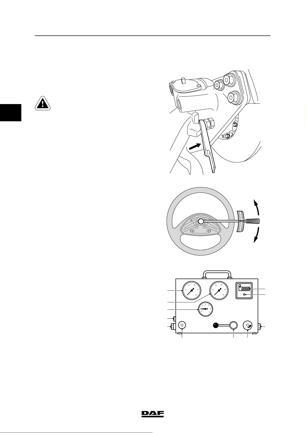
Testing the maximum system pressure
1. Run the engine at idling speed.
2. Turn the steering gear. Fit a 15 mm filler
piece, special tool (DAF no. 0535996),
between the adjusting bolt or the axle stop
on the swivel axle and axle housing stop.
Be careful when fitting the 15 mm
filler piece between the adjusting
bolt or the axle stop on the swivel
axle and the axle stop, as there is a
danger of limbs getting trapped.
S7 00 598
3. Fit a torque wrench with a dial to the
steering wheel attachment bolt. Tighten the
bolt to a tightening torque of 45 Nm on the
torque wrench.
4. Take the pressure reading on the pressure
gauge (10) (the maximum pressure must
not be maintained for more than 5
seconds). Compare the reading with the
specified value, see “Technical data”.
5. Repeat the measurement using the 15 mm
filler piece at the other end of the front axle.
9
10
11
1
3
5
10 15
45Nm
45Nm
S7 00 611
100 150
50
20
25
200
250
7
8
2
3-8
465
S7 00 020
ᓻ 200322
Page 71

7
STEERING GEAR, GENERAL
LF45/55 series Inspection and adjustment
Testing the final limiting pressure
1. Turn the steering gear to maximum lock.
2. Set the engine speed at 1200 - 1400 rpm.
3. Fit a torque wrench with a dial to the
steering wheel attachment bolt. Tighten the
bolt to a tightening torque of 45 Nm on the
torque wrench.
4. Read the final limiting pressure off the
pressure gauge (10).
5. Compare the reading with the specified
value, see “Technical data”.
45Nm
2
6. Carry out the measurement on the other
end of the axle.
Testing the maximum pump pressure
1. Check whether the pressure-limiting valve
(6) is set at the correct pressure.
2. While the engine is at idling speed, slowly
close the valve (4) until the maximum
pressure is reached on the gauge (10). The
maximum pressure may only be maintained
for 5 seconds. Otherwise the internal pump
components will become too hot. This
would result in premature wear in the pump.
The pressure is limited to 150 bar by the
pressure-limiting valve built into the test
equipment case.
Note:
Never turn the steering wheel when the
valve (4) is closed. The peak pressures
could damage the pump or the test case.
3. Open the valve (4).
4. Compare the reading with the specified
value, see “Technical data”.
45Nm
S7 00 611
ᓻ 200322
3-9
Page 72

2
STEERING GEAR, GENERAL
7
Inspection and adjustment LF45/55 series
Testing the pump output
1. Activate the output meter (7) using the
switch (8).
2. Set the engine speed at 1200 - 1400 rpm.
3. Close the valve (4) until the pressure gauge
(10) indicates the specified pump output
pressure, see “Technical data”.
4. Take the pump output reading at the output
meter (7) and compare this value to the
specified value, see “Technical data”.
Testing the steering pump flow-control valve
1. Activate the output meter (7) using the
switch (8).
2. Slowly increase the engine speed, until the
output meter (7) reading no longer rises.
Check whether the steering pump output is
stable and compare the measured value to
the specified value, see “Technical data”.
3. Increase and decrease the engine speed
and check whether the output increases
evenly and then remains stable.
4. Slowly close the valve (4) until the pressure
at the pressure gauge (10) has increased to
approx. 50 bar. While closing the valve,
check whether the pressure gauge (10)
needle starts to fluctuate.
9
10
11
1
3
5
10 15
20
25
100 150
50
200
250
465
S7 00 020
7
8
2
3-10
ᓻ 200322
Page 73

7
STEERING GEAR, GENERAL
LF45/55 series Inspection and adjustment
Testing for internal steering box leaks
1. Check that there is a line between the
“Tank” connection and the steering oil
reservoir. The line to the reservoir should
reach the bottom of the reservoir to prevent
foaming.
2. Open the non-return valve (5).
3. Close the valve (4) completely.
4. Adjust the pressure to 30 bar below the
maximum system pressure using the
non-return valve (5), see “Technical data”.
5. Open the valve (4) fully.
6. Activate the output meter (7) using the
switch (8).
7. Turn the steering gear. Fit a 15 mm filler
piece, special tool (DAF no. 0535996),
between the adjusting bolt or the axle stop
on the swivel axle and axle housing stop.
9
10
11
1
3
5
10 15
100 150
50
20
25
200
250
7
8
2
2
465
S7 00 020
8. Fit a torque wrench with a dial to the
steering wheel attachment bolt. Tighten the
bolt to a tightening torque of 45 Nm on the
torque wrench.
9. Read off the quantity of leaking oil and
compare this quantity to the maximum
permissible quantity of leaking oil, see
“Technical data”.
10. Carry out the measurement for the other
wheel deflection.
ᓻ 200322
S7 00 598
45Nm
45Nm
S7 00 611
3-11
Page 74

2
STEERING GEAR, GENERAL
7
Inspection and adjustment LF45/55 series
11. If the steering gear “jams”, the test should
be repeated with a set pressure of
15 - 30 bar.
Checking steering wheel bolt attachment
1. Retighten the steering wheel attachment
bolt to the specified tightening torque, see
“Technical data”.
Removing the test case
1. Remove the pipes and re-connect the
delivery pipe.
2. Check the steering oil level and top up as
necessary.
3. Bleed the system.
4. Inspect the pipe connections for leaks.
3.3 CHECKING THE STEERING BOX ATTACHMENT
1. Run the engine at idling speed.
2. Pull the steering wheel with quick jerks.
3. The steering box should not move.
3.4 CHECKING HYDRAULIC CENTRE POSITION
1. Jack up the front axle.
2. Check that the pitman arm is in the central
position.
3. Allow the engine to run at a speed of
1200 - 1400 rpm.
4. The pitman arm should not move by itself.
3-12
ᓻ 200322
Page 75

7
STEERING GEAR, GENERAL
LF45/55 series Draining, filling and bleeding
4. DRAINING, FILLING AND BLEEDING
4.1 DRAINING, FILLING AND BLEEDING STEERING GEAR, VERSION WITHOUT
STEERED TRAILING SWIVEL AXLE
The steering oil should be drained if:
- the steering pump is damaged
- the steering oil is dirty
- there is water in the steering oil
- there is serious foaming of the steering oil
due to air being drawn in.
Draining steering gear, version without
steered trailing swivel axle
Drained steering oil may not be
re-used. Store this hydraulic oil
separately from the other drained
oils and have the oil collected by an
authorised waste removal company.
1. Clean the steering box and reservoir
connection lines.
2
2. Jack up the steerable axle.
3. Place a receptacle under the steering box.
Take the return pipe off the steering box.
4. Turn the steering wheel slowly from one
end stop to the other until the oil stops
coming out of the pipe connection(s).
5. Reinstall the pipe which was disconnected.
6. Replace the reservoir and the integrated
filter if the steering pump is damaged or the
steering oil is dirty.
ᓻ 200322
4-1
Page 76

2
STEERING GEAR, GENERAL
7
Draining, filling and bleeding LF45/55 series
Filling/bleeding steering gear without
steered trailing swivel axle
Make sure that during filling and
bleeding the reservoir always
remains filled with oil in order to
prevent the pump from drawing in
air which would cause foaming in
the oil.
Air in the hydraulic system can
cause serious damage to the
steering pump. Air in the hydraulic
system can cause the steering gear
to jam occasionally.
If there is air in the hydraulic
system, a squealing noise will be
heard when the steering wheel is
turned.
If there is severe foaming, the
steering oil should be completely
drained.
Trace and repair the leak, after
which the system can be filled and
bled again.
1. Fill the reservoir to the top with clean oil
which complies with the specifications. Wait
a little while and then fill the reservoir to the
top again.
2. Crank the engine for approx. 2 seconds
using the starter motor. Make sure that the
reservoir stays filled. Stop cranking
immediately if the oil level becomes too low.
Topupthesteeringoil.
3. Crank the engine for approx. 10 seconds
using the starter motor. Make sure that the
reservoir stays filled. Stop cranking
immediately if the oil level becomes too low.
4-2
ᓻ 200322
Page 77

7
STEERING GEAR, GENERAL
LF45/55 series Draining, filling and bleeding
4. Top up the steering oil to the top mark on
the dipstick.
5. Repeat points 3 and 4 until the steering oil
level no longer decreases.
6. Jack up the steerable axle until the wheels
are clear of the floor.
7. Start the engine and, with the engine idling,
slowly turn the steering wheel (approx. a
turn per second) to anticlockwise and
clockwise until the maximum wheel
deflection is reached. Continue this until the
oil level no longer decreases.
Note the steering oil level.
8. Run the engine at idling speed for another 2
minutes. Do not touch the steering wheel
during these 2 minutes.
9. Check the steering oil level when the engine
is running and, if necessary, top up to the
top mark on the dipstick.
10. Stop the engine. The steering oil level must
not rise more than 2 cm above the max.
mark (A in drawing). If the steering oil level
rises by more than 2 cm, there is still air in
the system.
11. Put the filler cap on the reservoir again and
lower the axle.
12. Inspect the pipe connections for leaks.
13. Take a test drive. Check the steering oil
level again and check the pipe connections
for leaks.
1
/
2
2
max. 2 cm
A
Max.
Min.
ᓻ 200322
S7 00 023
4-3
Page 78

2
STEERING GEAR, GENERAL
7
Draining, filling and bleeding LF45/55 series
4.2 DRAINING, FILLING AND BLEEDING STEERING GEAR, VERSION WITH
STEERED TRAILING SWIVEL AXLE
Draining steering gear, version with steered
trailing swivel axle
Drained steering oil may not be
re-used. Store this hydraulic oil
separately from other drained oils
and have the oil collected by an
authorised waste-removal company.
1. Jack up the trailing axle and support the
axle on stands.
2. Place suitable trays beneath the
high-pressure filter (1), the steering cylinder
(2) and the valve block (3).
3. Clean the steering oil reservoir and the
surrounding area.
4. Take the filter element out of the steering oil
reservoir.
5. Clean the housing and the surrounding area
of the high-pressure filter. Remove the
high-pressure filter.
2
1
3
4-4
S7 00 801
ᓻ 200322
Page 79

7
STEERING GEAR, GENERAL
LF45/55 series Draining, filling and bleeding
6. Mark the position of the pipes on the
damper valve (1) and take the pipes off the
damper valves.
7. If necessary, mark the position of the
damper valves and remove the damper
valves.
8. Manually swivel the trailing axle a few times
so that the steering oil is gently released
from the steering cylinder.
9. Check the sealing rings of the damper
valves for wear and damage. Replace if
necessary.
10. Attach the damper valves in their correct
position on the steering cylinder.
The position of the damper valves
must not be changed under any
circumstances. Changing the
damper valves affects the vehicle’s
handling and steering
characteristics.
1
25 bar
33 bar
B
A
A B
S7 00 800
2
11. Using the marks made previously, attach
the pipes to the damper valves.
12. Fit a new high-pressure filter.
13. Fit a new filter element in the steering oil
reservoir.
Filling steering gear, version with steered
trailing swivel axle
1. Fill the reservoir to the top with clean oil
which complies with the specifications. Wait
a little while and then fill the reservoir to the
top again.
2. Crank the engine for approx. 2 seconds
using the starter motor. Make sure that the
reservoir stays filled. Stop cranking
immediately if the oil level becomes too low.
Topupthesteeringoil.
3. Crank the engine for approx. 10 seconds
using the starter motor. Make sure that the
reservoir stays filled. Stop cranking
immediately if the oil level becomes too low.
ᓻ 200322
4-5
Page 80

2
STEERING GEAR, GENERAL
7
Draining, filling and bleeding LF45/55 series
4. Top up the steering oil to the top mark on
the dipstick.
5. Repeat points 3 and 4 until the steering oil
level no longer decreases.
Make sure that during filling and
bleeding the reservoir always
remains filled with oil in order to
prevent the pump from drawing in
air which would cause foaming in
the oil.
6. Bleed the steering gear.
Bleeding steering gear, version with steered
trailing swivel axle
1. Gently turn the steering wheel in both
directions when the level in the reservoir is
dropping only slightly or stops dropping
altogether.
Note:
System failures can occur as a result of
even slight movements of the steering
wheel. The yellow warning will then be
visible on the DIP and the trailing axle will
no longer steer.
If a failure occurs, switch the vehicle ignition
off and then on again.
2. Check the steering oil level and let the
engine run idle for a few minutes.
3. Gently turn the steering wheel in both
directions and check the oil level. Top up oil
if necessary.
4. Make a test run and check the steering oil
level. Top up oil if necessary.
Note:
Any foaming that occurred during bleeding
should have disappeared after the test run.
4-6
ᓻ 200322
Page 81

7
STEERING BOX
LF45/55 series Contents
CONTENTS
Page Date
1. SAFETY INSTRUCTIONS 1-1 200322............................................... ....
2. GENERAL 2-1 200322............................................................ ....
2.1 Overview drawing of steering box 2-1 200322................................... ....
2.2 Overview drawing of wheel-deflection limiting valves 2-2 200322................... ....
2.3 Operation of the steering box 2-3 200322....................................... ....
3. INSPECTION AND ADJUSTMENT 3-1 200322....................................... ....
3.1 Inspection and adjustment, wheel-deflection limiting valves 3-1 200322............. ....
3.2 Inspecting the pressure point 3-6 200322....................................... ....
3.3 Inspection and adjustment, input shaft end play 3-8 200322....................... ....
4. REMOVAL AND INSTALLATION 4-1 200322........................................ ....
4.1 Removal and installation of steering box assembly 4-1 200322.................... ....
4.2 Removal and installation of steering bracket 4-5 200322.......................... ....
4.3 Removal and installation of pitman arm 4-7 200322.............................. ....
4.4 Removal and installation of pressure-limiting valve 4-11 200322.................... ...
4.5 Removal and installation of piston 4-12 200322................................... ...
3
ᓻ 200322
1
Page 82

3
7STEERING BOX
Contents LF45/55 series
2
ᓻ 200322
Page 83

7
STEERING BOX
LF45/55 series Safety instructions
1. SAFETY INSTRUCTIONS
If the vehicle is fitted with an airbag,
observe the warnings and safety
instructions applicable to working
on an airbag system.
Be careful when tilting the cab or
when working under a tilted cab if
the steering bracket has to be
inspected or replaced because of a
collision.
Vital parts of the cab suspension
may have been damaged during the
collision.
Take the necessary precautions.
If the vehicle has been involved in a collision, in
which the steering box or other steering gear
components (may) have been damaged, the
steering box must always be sent to DAF for
inspection or be replaced. This requirement still
applies even if no external damage is visible.
The steering box may have sustained internal
damage in the collision, causing it to be
unreliable.
3
If the pitman arm has been subjected to
extremely high loads (in an accident), it should
be magnaflux tested, even if no faults are
apparent to the naked eye.
If such a test is not possible, the pitman arm
should always be replaced.
The pitman arm should only be removed using
the specified special tool.
If the specified tools are not available, the
pitman arm should under no circumstances be
removed by dislodging it using a hammer or by
heating.
This would result in the pitman arm becoming
extremely unreliable and would also
permanently damage the sector shaft.
ᓻ 200322
1-1
Page 84

3
STEERING BOX
Safety instructions LF45/55 series
7
1-2
ᓻ 200322
Page 85

7
STEERING BOX
LF45/55 series General
2. GENERAL
2.1 OVERVIEW DRAWING OF STEERING BOX
3
A. Reservoir
B. Steering pump
C. Delivery pipe
D. Return pipe
E. Shim
F. Pivot bearing
G. Box
H. Piston
J. Ball nut
K. Worm shaft
ᓻ 200322
S7 00 265
L. Torsion bar
M. Pin (with internal end stop)
N. Pressure-limiting valve
O. Make-up valve (by-pass valve)
P. Input shaft
Q. Control valve core
R. Control valve casing
S. Sector shaft
T. C over
2-1
Page 86

3
STEERING BOX
7
General LF45/55 series
2.2 OVERVIEW DRAWING OF WHEEL-DEFLECTION LIMITING VALVES
1. Stop bolt
2. Sliding bush
3. Left-hand side of the piston
4. Left-hand wheel-deflection limiting valve
5. Piston
6. Guide pin
7. Spring
8. Right-hand wheel-deflection limiting valve
9. Right-hand side of the piston
10. Sliding bush
11. Stop bolt
2-2
S7 00 622
ᓻ 200322
Page 87

7
STEERING BOX
LF45/55 series General
2.3 OPERATION OF THE STEERING BOX
3
The drawing shows a longitudinal section of the
steering box with steering pump and reservoir
and a cross section of the control valve.
The steering pump and the lines are shown
schematically in the drawing.
The steering box is shown with the control valve
in the neutral position.
The steering box is a mechanical steering box
that is activated hydraulically.
ᓻ 200322
S7 00 265
2-3
Page 88

STEERING BOX
7
General LF45/55 series
Mechanical operation
The input shaft (P) is connected to the worm
shaft (K) by the torsion bar (L). Pin (M) which is
pressed into the input shaft limits the stroke of
the input shaft in relation to the worm shaft.
The torsion bar (L) which cannot transfer large
forces will twist as a result of mechanical
steering until the pin (M) in the input shaft (P) fits
abuts in the worm shaft (K). This pin transfers
the majority of the force.
The worm shaft is supported without any play in
the box (G) on two axial pivot bearings (F) and
shim (E).
3
If the steering wheel is turned, this movement is
transferred by the input shaft (P) into an axial
movement of the piston (H) through a ball nut (J)
with an endless raceway which is integrated into
the piston (H).
This movement is transferred to the sector shaft
(S) via the toothing of the piston and the sector
shaft (S). The pitman arm connected to the
sector shaft will also turn, as will the steerable
wheels via the steering rod.
The piston/sector shaft toothing has a variable
pitch. In the central position the transmission is
more direct, outside the central position the
transmission is less direct.
This mechanical process is hydraulically
assisted.
2-4
ᓻ 200322
Page 89

7
STEERING BOX
LF45/55 series General
Hydraulic operation
The hydraulic part consists of a cylinder with
piston and a control valve (Q) which is
integrated into the input shaft/worm shaft. The
oil enters the steering box at the top. The oil
leaves the steering box at the bottom through
the control valve and the hollow worm. This
design keeps the steering box at a more even
temperature, even when there is no steering
action.
The core (Q) of the control valve and the input
shaft (P) form part of a single unit. The casing
(R) of the control valve and the worm shaft (K)
form part of a single unit.
The input shaft (P) is supported in the worm
shaft (K). The input shaft and the worm shaft
both have six recesses.
The recesses on the input shaft (P) are
connected alternately, with three to the delivery
pipe (C) and three to the return pipe (D.
The recesses in the worm (K) are connected
alternately, with three to the left-hand side and
three to the right-hand side of the piston.
3
In the neutral control valve position the recesses
of the input shaft (P) and the worm (K) are
positioned in relation to one another in such
away that the left-hand and the right-hand sides
of the piston are connected to both the delivery
pipe (C) and the return pipe (D).
The forces exerted on the left-hand and
right-hand side of the piston (H) are equal and
there is a hydraulic central position. The neutral
position of the control valve is factory set during
the manufacture of the steering box.
ᓻ 200322
2-5
Page 90

3
STEERING BOX
7
General LF45/55 series
The input shaft (P) is connected to the worm
shaft (K) by the torsion bar (L).
When the steering wheel is turned the torsion
bar will twist as a result of the friction between
the tyre and the road surface. The two parts of
the control valve (Q and R) turn in relation to
one another, changing the oil flow to and from
the piston.
If the steering wheel is turned to the right,
pressure builds up on the left-hand side of the
piston and the right-hand side is connected to
the return pipe. The piston will move to the right.
If the force on the input shaft (P) is reduced, the
torsion bar (L) will twist back and the control
valve will return to its neutral position, thus
recovering the hydraulic central position.
If the steering wheel is turned to the left,
pressure builds up on the right-hand side of the
piston (H) and the left-hand side is connected to
the return pipe (D). The piston will move to the
left.
Pressure-limiting valve
The task of the pressure-limiting valve is to
protect the system from being overloaded.
The design is very simple and, therefore,
relatively insensitive to dirt. The opening
pressure is stamped on the valve. The valve
cannot be dismantled or adjusted, but can be
supplied with various opening pressures.
2-6
ᓻ 200322
Page 91

7
STEERING BOX
LF45/55 series General
Wheel-deflection limiting valves
The task of the wheel-deflection limiting valves
is to limit the pressure at maximum wheel
deflection. Otherwise, the pressure could
increase to the level at which the pressure-relief
valve activates.
In that case, there would be a heavy load on the
mechanical part of the steering gear. If this
situation were to last for too long, the steering
pump could be damaged.
3
In the steering box, two wheel-deflection limiting
valves (4 and 8) are integrated into the piston
(5). The valves cannot be dismantled.
ᓻ 200322
S7 00 622
2-7
Page 92

;;
;;
;;
;;
3
STEERING BOX
7
General LF45/55 series
The wheel-deflection limiting valves slide over a
guide pin (6).
When the pressure on both sides of the piston
(5) is equal, the spring (7) pushes them onto
their seats.
The left-hand side (3) of the drawing shows the
delivery pressure and the right-hand side (9) the
return pressure.
In this situation the wheel-deflection limiting
valve (4) on the piston delivery side is forced off
its seat for a short time against the spring
pressure. The chamber between the
wheel-deflection limiting valves is now also
pressurised and the valve (8) is pressed more
firmly onto its seat.
The piston (5) will move to the right. Before the
end of the piston stroke is reached the pin of the
right-hand wheel-deflection limiting valve (8) will
hit the stop bolt (11).
Valve (8) is now pushed off its seat.
The pressure in the chamber between the
wheel-deflection limiting valves now drops and
at the same time the left-hand valve (4) is
opened again by the pressure.
The left-hand and right-hand sides of the piston
are connected together, thereby decreasing the
pressure.
The wheel-deflection limiting valves are set
automatically in a new steering box.
The stop bolts (1 and 11) have a sliding bush (2
and 10). In a new steering box the sliding
bushes (2 and 10) are the maximum length. The
first time that the steering gear is rotated fully
(anticlockwise and clockwise), the piston (5)
touches the sliding bush (2 or 10) before
reaching the maximum wheel deflection and
pushes the bush further to the stop bolt (1 or
11). This sets both wheel-deflection limiting
valves correctly.
If the wheel deflection is reduced, the
wheel-deflection limiting valves must be reset.
The stop bolts (1 and 11) must be replaced for
this procedure.
5 10 11
S7 00 621
2-8
ᓻ 200322
Page 93

7
STEERING BOX
LF45/55 series General
Pressure point
The sector shaft has right toothing.
Both bearing races supporting the sector shaft
are eccentrically formed.
By turning both bearing races simultaneously in
the box, the distance between the sector shaft in
relation to the piston can be changed.
When adjusting the pressure point the bearing
races are turned until the middle tooth of the
sector shaft (the largest tooth) engages the
piston toothing correctly.
Note:
Adjustment of the pressure point should only
take place in a workshop designed for this
purpose and using the required special tools.
Steering box angle sensor on version with
steered trailing swivel axle
An angle sensor (4) is fitted to the steering box
on the version with a steered trailing swivel axle
The angle sensor sends data on the steering
angle to the RAS-EC system electronic unit.
1
2
The angle sensor and the protective cover (5)
are fitted to the attachment cover (3). The carrier
(2) transfers the rotation of the sector shaft to
the angle sensor.
The carrier is connected to the sector shaft by
tension bushes (1).
3
4
5
3
S7 00 831
ᓻ 200322
2-9
Page 94

3
STEERING BOX
General LF45/55 series
7
2-10
ᓻ 200322
Page 95

7
STEERING BOX
LF45/55 series Inspection and adjustment
3. INSPECTION AND ADJUSTMENT
3.1 INSPECTION AND ADJUSTMENT, WHEEL-DEFLECTION LIMITING VALVES
Inspecting wheel-deflection limiting valves
1. If the vehicle has a steered trailing swivel
axle, remove the RAS-EC system fuse.
2. Connect the pressure gauge to the T-piece
in the delivery pipe using the special tool
(DAF no. 0535653). Connect the T-piece as
quickly as possible to prevent air getting
into the system.
Check the steering oil level in the reservoir
after connecting the T-piece and top up the
oil if necessary.
Only use couplings and pipes which
are suitable for the maximum
system pressure.
3. Bleed the steering gear.
S7 00 614
3
4. Jack up the front axle.
5. Warm up the steering oil as described
below, until the pipes are at least warm to
the touch.
- Set the engine speed at
1200 - 1400 rpm.
- Activate the steering gear for 5
seconds at its maximum, making sure
that the pressure does not exceed
50 bar.
- Do not touch the steering wheel for 5
seconds.
- Repeat this procedure until the pipes
are at least warm to the touch.
Note:
If the steering oil is too cold, considerably
higher pressures will be measured.
6. Turn the steering wheel fully to the left.
7. Set the engine speed at 1200 - 1400 rpm.
ᓻ 200322
3-1
Page 96

3
STEERING BOX
7
Inspection and adjustment LF45/55 series
8. Fit a torque wrench with a dial to the
steering wheel attachment bolt and tighten
the bolt to a tightening torque of 45 Nm on
the torque wrench.
Note:
The pressure must never exceed the
maximum permissible final limiting
pressure. If the pressure rises too high, the
valve should be reset before the
measurement is continued.
9. The pressure gauge will indicate the final
limiting pressure. Compare the reading to
the specified value, see “Technical data”.
Do not maintain this pressure for more than
5 seconds.
If the reading is outside the specified
values, the final limiting valve should be
readjusted.
10. Carry out the measurement once again,
with the steering wheel turned fully to the
right.
The left-hand and right-hand pressures do
not need to be exactly the same.
45Nm
45Nm
S7 00 611
11. Remove the jack.
12. Remove the T-piece.
13. Check the steering oil level in the reservoir
and top up if necessary.
14. Bleed the steering gear.
15. Retighten the steering wheel attachment
bolt to the specified tightening torque, see
“Technical data”.
16. If the vehicle has a steered trailing swivel
axle, fit the RAS-EC system fuse.
3-2
ᓻ 200322
Page 97

7
STEERING BOX
LF45/55 series Inspection and adjustment
Adjusting the wheel-deflection limiting
valves
There are three procedures for making
adjustments.
Procedure A, to be used if:
- a new or overhauled steering box is fitted.
Procedure B, to be used if:
- the wheel deflection has been increased.
Procedure C, to be used if:
- the wheel deflection has been reduced.
- the steering box input shaft was rotated to
the end stop before the steering box with
the steering rod was connected to the
steering gear.
Adjustment following procedure A
1. Make sure that the attachment bolts of the
steering box and of the steering bracket are
tightened to the specified tightening
torques, see “Technical data”.
3
2. Check the wheel deflection of the front axle
before the steering rod is installed. If
necessary, the wheel deflection should be
adjusted using the wheel deflection stop
bolts on the swivel axles.
3. Install the steering rod.
4. Turn the steering wheel fully anticlockwise
and clockwise with the engine running. The
wheel deflection stop bolts or end stop
points must abut the axle housing for this
procedure.
If the maximum wheel deflection is not
reached, partially unload the front axle by
jacking it up so that the maximum wheel
deflection is reached. Never completely
unload the front axle when doing this.
The stop bolt sliding bushes are now
pushed further onto the stop bolts. This
gives the correct setting for the wheel
deflection limiting valves.
ᓻ 200322
3-3
Page 98

3
STEERING BOX
7
Inspection and adjustment LF45/55 series
Adjustment following procedure B
1. The wheel deflection must be increased
using the wheel deflection stop bolts on the
swivel axles.
2. Turn the steering wheel fully anticlockwise
and clockwise with the engine running. The
wheel deflection stop bolts must abut the
axle housing for this procedure.
If the maximum wheel deflection is not
reached, partially unload the front axle by
jacking it up so that the maximum wheel
deflection is reached. Never completely
unload the front axle when doing this.
The stop bolt sliding bushes are now
pushed further onto the stop bolts. This
gives the correct setting for the wheel
deflection limiting valves.
3-4
ᓻ 200322
Page 99

7
STEERING BOX
LF45/55 series Inspection and adjustment
Adjustment following procedure C
1. The wheel deflection must be reduced using
the stop bolts on the swivel axles.
2. Remove both stop bolts and replace them
with new ones.
Tighten the new stop bolts to the specified
tightening torque, see “Technical data”.
If the steering oil has not been drained,
place a tray under the steering box. When
the stop bolt is removed, steering oil will
come out of the opening.
Note:
The sliding bush of a used stop bolt musst
not be taken off the stop bolt and the stop
bolt re-fitted.
3. Fill and bleed in the case of an integrated
steering box and steering gear.
4. Turn the steering wheel fully anticlockwise
and clockwise with the engine running. The
wheel deflection stop bolts must abut the
axle housing for this procedure.
If the maximum wheel deflection is not
reached, partially unload the front axle by
jacking it up so that the maximum wheel
deflection is reached. Never completely
unload the front axle when doing this.
The stop bolt sliding bushes are now
pushed further onto the stop bolts. This
gives the correct setting for the wheel
deflection limiting valves.
S7 00 620
3
ᓻ 200322
3-5
Page 100

3
STEERING BOX
7
Inspection and adjustment LF45/55 series
3.2 INSPECTING THE PRESSURE POINT
Inspecting the pressure point
1. Drain the steering oil.
2. Take the steering rod off the pitman arm.
Note:
If a steering rod is removed, the input shaft
must not be rotated more than one turn
(starting from the central position).
Otherwise, the setting of the wheel
deflection limiting valves will be changed.
3. Place the sector shaft in the central
position, by aligning the marks on the sector
shaft and the steering box.
4. Take the universal joint off the input shaft.
5. If the vehicle has an airbag, use adhesive
tape or some other means to prevent the
steering wheel from turning.
If the steering wheel is rotated more
than 3 turns to the left or right from
the central position, this will
damage the airbag contact unit.
6. Check whether the sector shaft is still in the
central position, using the marks.
7. Fit a micrometer (A) to the
resistance-torque tester (ZF order number
8090 798 151).
3-6
ᓻ 200322
 Loading...