

Page 1

0
ΛΦ45/55 series
STRUCTURE
Structure
TECHNICAL DATA
0
1
SAFETY INSTRUCTIONS AND WARNINGS
2
THREADED CONNECTIONS
3
SEALS AND BEARINGS
4
GENERAL OPERATIONS
5
PAINT TREATMENT
6
CONVERSION TABLES
7
©
200338
Page 2

Page 3

0
TECHNICAL DATA
ΛΦ45/55 series
0 Technical dat a
CONTENTS
Page Date
1. VEHICLE MODELS. . . . . . . . . . . . . . . . . . . . . . . . . . . . . . . . . . . . . . . . . . . . . . . 1-1 . . . . . 200338
1.1 Overview . . . . . . . . . . . . . . . . . . . . . . . . . . . . . . . . . . . . . . . . . . . . . . . . . 1-1 . . . . . 200338
2. LOCKING COMPOUNDS AND SEALANTS . . . . . . . . . . . . . . . . . . . . . . . . . . . 2-1 . . . . . 200338
2.1 General . . . . . . . . . . . . . . . . . . . . . . . . . . . . . . . . . . . . . . . . . . . . . . . . . . 2-1 . . . . . 200338
3. THREADED CONNECTIONS . . . . . . . . . . . . . . . . . . . . . . . . . . . . . . . . . . . . . . . 3-1 . . . . . 200338
3.1 Tightening torques . . . . . . . . . . . . . . . . . . . . . . . . . . . . . . . . . . . . . . . . . . . 3-1 . . . . . 200338
4. PAINT TREATMENT . . . . . . . . . . . . . . . . . . . . . . . . . . . . . . . . . . . . . . . . . . . . . . 4-1 . . . . . 200338
4.1 Overview of plastics used . . . . . . . . . . . . . . . . . . . . . . . . . . . . . . . . . . . . . 4-1 . . . . . 200338
Contents
0
©
200338 1
Page 4

TECHNICAL DATA
0
0
Contents
ΛΦ45/55 series
2
©
200338
Page 5
0
TECHNICAL DATA
ΛΦ45/55 series
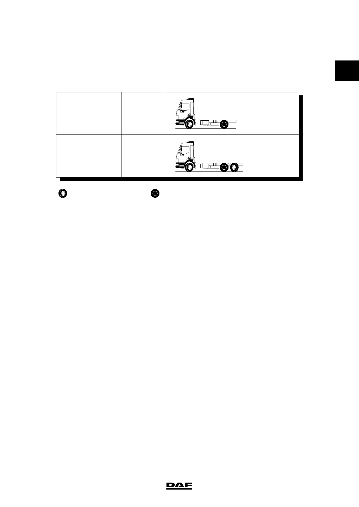
1. VEHICLE MODELS
1.1 OVERVIEW
FT
FA
FAN
steered axle driven axle
Vehicle models
0
4 x 2
6 x 2
G0 00 205
©
200338 1-1
Page 6

TECHNICAL DATA
0
0
Vehicle models
ΛΦ45/55 series
1-2
©
200338
Page 7

0
TECHNICAL DATA
ΛΦ45/55 series
Locking compounds and sealants
2. LOCKING COMPOUNDS AND SEALANTS
2.1 GENERAL
Certain cleaning agents have a
negative effect on the functioning of
}
Product
name
Loctite
243
Loctite
2701
locking compounds. The general
rule is therefore that fasteners and
components which have been
cleaned with a cleaning agent must
be treated with a cleaning liquid to
ensure that the locking compound
functions properly.
OVERVIEW OF LOCKING COMPOUNDS
Properties Applications DAF
- Locking with an average
detaching strength
- Detachable with normal tools
- Locking with a high detaching
strength
- Repairs the fit in bearing
housings
- Seals against leaks
- Difficult to detach
Locking of threaded connections 0068197
Locking of threaded connections,
gear lever ball, freeze plugs
0
number
1340646
Loctite
638
Loctite
648
Loctite
262
- Locking with a high detaching
strength under dynamic load
- Difficult to detach
- Locking with an average
detaching strength
- Resistant to high temperatures
- Locking with a high detaching
strength
- Difficult to detach
Locking of cylindrical connections 0645557
Locking of threaded connections in
warm places
Locking of threaded connections,
such as the pinion nut
1357032
1279841
©
200338 2-1
Page 8

TECHNICAL DATA
0
0
Locking compounds and sealants
Applying the locking compound
1. Clean both the internal and external threads.
Degrease the thread with a suitable
degreasing agent which leaves no residue
that could affect proper functioning.
2. Apply one or more drops of locking
compound to the thread, depending on the
diameter. Never dip the bolt or stud fully into
the locking compound.
3. Apply a drop of oil under the bolt head.
Locking compounds also reduce the
frictional resistance, which means that
applying a drop of oil to the thread is not
required.
4. Tighten the connection to the specified
torque.
OVERVIEW OF SEALING COMPOUNDS
Product
name
Properties Applications DAF
ΛΦ45/55 series
number
Dirko D - Resistant to temperatures up to
180″C
- Resistant to oil, coolant
Loctite
510
Loctite
574
Loctite
Blue
Loctite
ultra grey
Loctite
ultra
copper
Loctite
5910
- Resistant to temperatures up to
200″C
- Resistant to oil, brake fluid,
coolant
- Resistant to high pressures (up to
350 bar)
- Resistant to oil, brake fluid,
coolant
- Resistant to temperatures from
60″C to 260″C
- Resistant to oil
- Silicone sealant, good resistance
to coolant
- Resistant to temperatures up to
325″C
- Silicone sealant, good resistance
to oil
- Resistant to temperatures of up
to 350″C
- Silicone sealant, good resistance
to oil
- Resistant to temperatures up to
200″C
Sealing of surface connections 1345014
Sealing of surface (flange)
connections that are subjected to high
operating temperatures, such as the
flywheel housing
Sealing of surface connections
against high pressures
Sealing of flexible constructions such
as (valve) covers
Sealing of (surface) connections in
the cooling system
Sealing of surface connections such
as hub covers
Sealing of surface connections, such
as front and rear covers of gearboxes,
differential housings, hub covers, stub
axle flanges and oil cooler
0697149
1246867
1242895
1284123
1284122
1360102
Loctite
572
2-2
- Seals against low pressure
immediately after fitting
Threaded connections 0292336
©
200338
Page 9

0
TECHNICAL DATA
ΛΦ45/55 series
OVERVIEW OF SEALING COMPOUNDS
Product
name
Loctite
5205
Loctite
Form a
gasket
Product
name
Tectyl Protects the cavities of the cab body
Properties Applications DAF
- Surface sealant, specially
designed for sealing aluminium
parts
- Resistant to temperatures up to
150″C
- Resistant to water, coolant and oil
- Hardens on contact with metal
and on full closure
OTHER PRODUCTS
Properties Applications DAF
against corrosion.
Locking compounds and sealants
number
Sealing of aluminium parts 1441339
For locking, fastening and sealing 1322823
number
Post-treatment of cab parts to protect
against corrosion.
Can also be used as protection for
metal parts
1343888
0
Contact
spray
Loctite
cleaner
7063
Molykote
BR 2
PLUS
Molykote
P37
Copaslip - Copper paste with an excellent
Cleaning agent for cleaning and
degreasing electronic and electrical
connections. Removes moisture and
dirt from electrical contacts
- Cleans and degreases
- Non-inflammable and noncorrosive
- Lubricating grease is heatresistant from -30″C to +130″ C
- Grease protects against
corrosion and is heat-resistant to
1400″C.
bond, is anti-corrosive and heatresistant from -35″C to 1100″C.
- Resistant to water, salts and
acids.
- Prevents wear, oxidation, rust,
corroding and locking of metal
surfaces.
Cleaning of electrical contacts 1387608
For cleaning/degreasing of materials
to which a locking compound must be
applied
- Wherever grease lubrication is
appropriate and normal
- For almost all ball and roller
bearings, plain bearings, guides,
couplings, splined shafts,
threaded spindles, sprocket
drives with a low speed
For threaded connections that are
exposed to high temperatures, as
used for exhaust systems
For connections that are vulnerable to
oxidation or corrosion, such as battery
terminals, exhaust couplings, etc.
1322827
1389512
1391619
1284344
Renolit
HLT2
©
200338 2-3
- Grease (white) Disc brake adjustment device 1448907
Page 10

TECHNICAL DATA
0
0
Locking compounds and sealants
Product
name
Syntheso
GL EP1
Gleitmo
805
Properties Applications DAF
- Grease (green) Rubber guides for disc brake 1448908
- Protects untreated metals
against corrosion
OTHER PRODUCTS
For parts which are attached with a fit
such as wheel hub units
ΛΦ45/55 series
number
1443160
2-4
©
200338
Page 11

0
TECHNICAL DATA
ΛΦ45/55 series
3. THREADED CONNECTIONS
3.1 TIGHTENING TORQUES
The tightening torques in the table below are
standard torques and only apply to dipped
threaded connections.
The property codes are stamped on the nut and
bolt, except on the clamping flange bolt. The
clamping flange bolt is recognised by a
constriction between the hexagonal bolt head
and the flange. This constriction is absent in
standard flange bolts.
Threaded connections
0
M2 00 001
Clamping flange bolt/standard-flange bolt
Tightening torques for dipped threaded
connections
Overview of standard tightening torques for
DAF flange bolts and nuts, strength class
10.9/10
Thread pitch Tightening torque (Nm) Extra angular displacement (≥ 10 %)
for bolt stem length L (mm):
L40 41-80 81-130 131-180
M8 30 ≥ 230″ 60″ 90″ 120″
M10 60 ≥ 445″ 90″ 120″ 150″
M12 x 1.75
M12 x 1.25
M14 x 2
M14 x 1.5
M14 x 2 for brake back plates: 170 ≥ 15 Nm + 60″
M16 x 2
M16 x 1.5
110 ≥ 8
110 ≥ 8
170 ≥ 15
170 ≥ 15
260 ≥ 20
260 ≥ 20
30″
45″
30″
45″
30″
45″
60″
90″
60″
90″
60″
90″
90″
120″
90″
120″
90″
120″
120″
150″
120″
150″
120″
150″
M18 x 2.5
M18 x 1.5
M20 x 1.5 520 ≥ 40 45″ 90″ 120″ 150″
M22 x 2.5 for steering and track rods: 500 ≥ 50 Nm + 90″
©
200338 3-1
360 ≥ 30
360 ≥ 30
30″
45″
45″
90″
60″
120″
80″
150″
Page 12
TECHNICAL DATA
0
0
Threaded connections
The bolt stem length L is the length of the bolt
between the bolt head and the nut.
If a component is attached with several bolts, all
bolts must first be tightened to the specified
torque, and subsequently by the angular
displacement.
Overview of standard tightening torques for
DAF fastenings, strength class 8.8/8
Thread Tightening torque
in Nm
M4 2.8 ≥ 0.2
M5 5.5 ≥ 0.4
M6 9.6 ≥ 0.7
M8 23 ≥ 2
M10 46 ≥ 4
M12 79 ≥ 6
M14 125 ≥ 9
M16 195 ≥ 14
ΛΦ45/55 series
M18 280 ≥ 20
M20 395 ≥ 30
M22 540 ≥ 40
M24 680 ≥ 50
M27 1000 ≥ 70
M30 1350 ≥ 100
Overview of standard tightening torques for
DAF flange bolts and nuts, strength class
12.9/12
Thread Tightening torque
in Nm
M8 32 ≥ 3
M10 67 ≥ 5
M12 113 ≥ 9
M14 178 ≥ 14
M16 274 ≥ 22
M18 385 ≥ 30
M20 550 ≥ 43
M22 740 ≥ 60
M24 925 ≥ 72
M27 1370 ≥ 110
3-2
©
200338
Page 13

0
TECHNICAL DATA
ΛΦ45/55 series
Overview of standard tightening torques for
DAF clamping flange bolts and nuts, strength
class 12.9/12
Thread Tightening torque
in Nm
M12 178 ≥ 14
M14 274 ≥ 22
M16 425 ≥ 35
M18 550 ≥ 45
Overview of tightening torques, banjo bolts
Thread Tightening torque
in Nm
M6 8 ≥ 0.8
M8 15 ≥ 1.5
M10 30 ≥ 3
M12 40 ≥ 4
Threaded connections
0
M14 50 ≥ 5
M16 60 ≥ 6
M18 70 ≥ 7
Torque wrench
- Have torque wrenches regularly inspected
and calibrated.
Re-use of fasteners (bolt/nut/threaded end)
1. Clean the thread (take particular care to
remove locking compound residues) and the
clamping faces
2. Check the thread for damage.
To do so, manually screw a new nut/bolt onto
the thread to be checked.
If the new nut/bolt cannot be fully handscrewed onto the entire thread of the
fastener to be checked, the fastener is not
allowed to be re-used.
3. Apply one drop of engine oil to the upper turn
of the bolt (threaded end)/lower turn of the
nut and one drop to the clamping faces
(other lubricants are not allowed).
4. If a locking compound has been specified, oil
should not be applied to the thread.
©
200338 3-3
Page 14

TECHNICAL DATA
0
0
Threaded connections
New bolts/nuts
New DAF bolts and DAF nuts, except bolts M4 to
M8 with inner-Torx, have already been lubricated.
If bolts have not yet been lubricated, a lubricant
should be applied.
1. Apply one drop of engine oil to the first turn
of the bolt/lower screw thread of the nut and
one drop to the clamping faces (other
lubricants are not allowed).
2. If a locking compound has been specified, oil
should not be applied to the thread.
ΛΦ45/55 series
3-4
©
200338
Page 15

0
TECHNICAL DATA
ΛΦ45/55 series
4. PAINT TREATMENT
4.1 OVERVIEW OF PLASTICS USED
1 SMC polyester
2 Thermoplastic polymer parts (ASA or ABS)
3 Fibre-glass reinforced polyester
1
2 2 1 2 1 1
Paint treatment
0
3
3
G0 00 206
©
200338 4-1
Page 16

TECHNICAL DATA
0
0
Paint treatment
ΛΦ45/55 series
4-2
©
200338
Page 17

0
LF45/55 series Contents
SAFETY INSTRUCTIONS AND WARNINGS
CONTENTS
Page Date
1. SAFETY INSTRUCTIONS AND WARNINGS 1-1 0201.............................. ......
1.1 General safety instructions 1-1 0201......................................... ......
1.2 Batteries 1-4 0201......................................................... ......
1.3 Welding 1-5 0201......................................................... ......
1.4 Jump-starting 1-8 0201.................................................... ......
1.5 Plastic pipes 1-9 0201..................................................... ......
1.6 Wiring harnesses 1-12 0201................................................. .....
1.7 Avoiding the risk of fire 1-13 0201............................................ .....
1.8 Tachograph calibration 1-14 0201............................................. .....
1.9 Airbag and seat belt tensioner 1-15 0201...................................... .....
2
ǹ 0201
1
Page 18

2
0SAFETY INSTRUCTIONS AND WARNINGS
Contents LF45/55 series
2
ǹ 0201
Page 19
0
SAFETY INSTRUCTIONS AND WARNINGS
LF45/55 series Safety instructions and warnings
1. SAFETY INSTRUCTIONS AND WARNINGS
1.1 GENERAL SAFETY INSTRUCTIONS
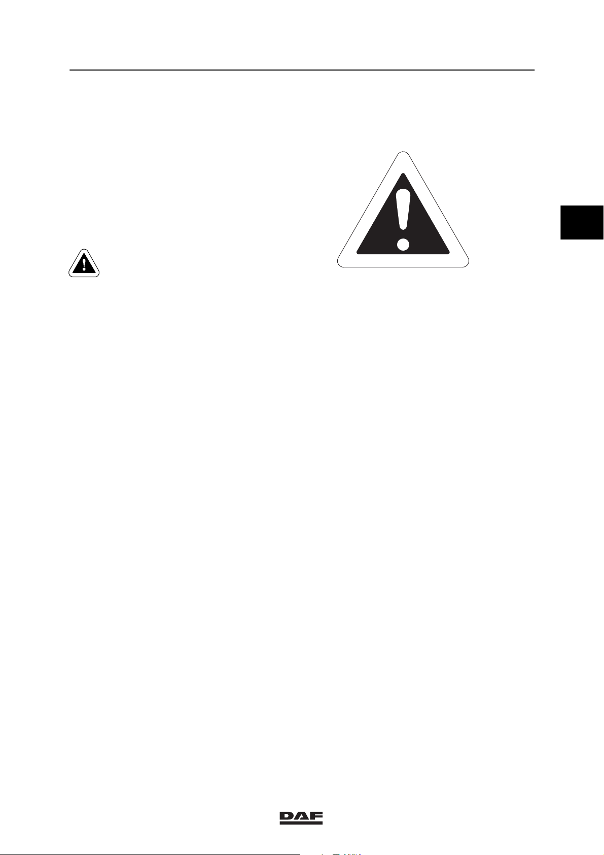
Warning symbol
When text is accompanied by the warning
symbol shown here, this indicates that the
information provided is essential for the health
and personal safety of the mechanic.
This warning symbol is also shown if
circumstances threaten the safety of the vehicle
or could lead to damage to the vehicle.
If any of the safety instructions and
warnings contained in this section
are ignored, the health and safety
ofthemechanicmaybeputatrisk.
Also, serious damage to the vehicle
or even a hazardous situation may
result.
- Comply with all the warnings and safety
instructions given in this workshop manual.
First read the instructions and warnings on
the labels and stickers which are affixed to
the various components and comply with
them. They have been put there for your
health and safety, so do not ignore them!
M0015
2
- Wear clean, fitted clothes and apply
protective cream, if necessary, to
unprotected parts of your body.
- Always disconnect the earth connection of
the battery before working on the vehicle.
- Do not run the engine in an enclosed or
unventilated area. Make sure exhaust
fumes are properly extracted.
ǹ 0201
1-1
Page 20

2
SAFETY INSTRUCTIONS AND WARNINGS
0
Safety instructions and warnings LF45/55 series
- Remain at a safe distance from rotating
and/or moving components.
- Do not remove the filler cap from the
cooling system when the engine is at
operating temperature.
- Be careful when changing the oil. Hot oil
can cause serious injuries.
- Avoid unnecessary contact with drained oil.
Frequent contact damages the skin.
- Various sorts of oil and other lubricants
used on the vehicle may constitute a health
hazard. This also applies to engine coolant,
clutch fluid, windscreen washer fluid,
refrigerant in air-conditioning systems,
battery acid and diesel fuel. So avoid
inhaling and direct contact.
- Tilt the cab fully if work must be carried out
underneath the cab.
- Always use stands to support the chassis or
components when working under the
vehicle.
- Be careful when working on activated
springs, such as those in spring brake
cylinders, valves, and similar. Inadvertently
released springs may cause serious
injuries. Small springs and circlips may also
cause injuries when inadvertently released
(wear goggles).
- Alwaysuseatyrecagewhenfittingand
inflating tyres. Thoroughly clean tyres prior
to balancing. Only use a balancing device
fitted with a protective cover.
1-2
ǹ 0201
Page 21

0
SAFETY INSTRUCTIONS AND WARNINGS
LF45/55 series Safety instructions and warnings
- Always use the appropriate lifting gear
(gearbox jack) or approved hoists for the
removal and installation of heavy
components. Attach the component
securely to the lifting or hoisting gear.
- Be careful when working on systems which
may be under pressure, such as a trailing
axle lifting device, cab tilting mechanism,
brake system, steering gear, fuel system,
etc.
- After a fire, hazardous residues may remain
fromtheplasticsusedinsomeoilsealsand
sealing rings. Wear protective,
acid-resistant clothing and PVC gloves
when removing such fire residues. Immerse
such fire residues in, or sprinkle them
amply with, a calcium hydroxide solution
(slaked lime and water). Thoroughly clean
the protective clothing after use. Treat the
gloves as chemical waste.
2
ǹ 0201
1-3
Page 22

2
SAFETY INSTRUCTIONS AND WARNINGS
0
Safety instructions and warnings LF45/55 series
1.2 BATTERIES
Always charge batteries in a
properly ventilated area and avoid
sparking and naked flames. Always
switch the battery charger off
before removing the leads.
Fast-charging should only be
resorted to in an emergency.
Disconnect the battery leads when
fast-charging is being used.
Wear protective clothing, gloves
and a visor when carrying out work
that may bring you into contact
with battery acid.
Battery acid is an aggressive fluid.
In the event of contact with the
skin: rinse the skin with plenty of
water for a sustained period. If
redness or pain persists, consult a
doctor. Remove any clothing
affected and rinse with water.
In the event of contact with the
eyes: Rinse with plenty of water for
at least 15 minutes and see a
doctor.
If any is swallowed: do NOT induce
vomiting. Rinse the mouth, drink
two glasses of water and see a
doctor.
In the event of inhalation: get some
fresh air, rest and consult a doctor.
To prevent damage to electronic components,
never disconnect the battery terminals when the
engine is running.
Always disconnect the earth connection of the
battery before working on the vehicle. Never
place tools on a battery. If you do, this could
short-circuit the battery or even cause the
battery to explode.
Always charge batteries in a properly ventilated
area and avoid sparking and naked flames.
When charging batteries, an explosive gas
mixture may be released.
1-4
ǹ 0201
Page 23

0
SAFETY INSTRUCTIONS AND WARNINGS
LF45/55 series Safety instructions and warnings
1.3 WELDING
No welding of the chassis is
allowed without special, written
permission by DAF. Exceptions to
the above are the welding
operations described in the manual
“Superstructure directives”.
Non-compliance with welding
regulations may cause serious
damage to the chassis.
Failure to observe the following
instructions may damage the
electronic components.
General
- Attach the earth clamp of the welding set as
close as possible to the area on the vehicle
wheretheweldingistobedoneandensure
that it is well in contact with the part being
welded.
- Never attach the earth clamp to vehicle
components such as the engine, axles,
springs, etc. Arcing on these components is
also not permitted. Non-compliance with the
above instructions may result in serious
damage to bearings, springs, etc.
- The accessory or ignition position of the
ignition lock must not be switched on.
Remove the ignition key from the ignition
lock.
- Protect plastic piping, rubber components,
plastic components, piston rods of hydraulic
cylinders and springs (in particular parabolic
springs) from welding splashes and
temperatures above 70_C.
2
ǹ 0201
1-5
Page 24

2
SAFETY INSTRUCTIONS AND WARNINGS
0
Safety instructions and warnings LF45/55 series
Welding on the chassis
- When welding on the chassis, disconnect
the connectors of all electronic equipment
(including sensors and actuators), if they
are within a 1-metre radius from the point
being welded or within a 1-metre radius
from the earthing point.
- Disconnect the battery terminals if these
arewithinawithina1-metreradiusfromthe
point being welded or the earth clamp.
- If the battery terminals have to be
disconnected, all electronic units mounted
on the chassis must be disconnected as
well. Also disconnect the cab feed-through
connectors and disconnect the power
supply and earth cables that are connected
to the cab.
Welding on the cab
- When welding on the cab, disconnect the
battery terminals.
- Also disconnect the cab feed-through
connectors and disconnect the power
supply and earth cables that are connected
to the cab.
- Disconnect the connectors of all electronic
equipment (including sensors and
actuators), if they are within a 0.5-metre
radius from the point being welded or within
a 0.5-metre radius from the earth terminal.
Welding on the superstructure
- Follow the instructions for “Welding on the
chassis”, together with any specific welding
instructions for welding on the
superstructure.
Note:
During grinding, protect plastic piping, rubber
components, plastic components, piston rods of
hydraulic cylinders and springs (in particular
parabolic springs) in order to prevent damage
caused by grinding sparks.
1-6
ǹ 0201
Page 25

0
SAFETY INSTRUCTIONS AND WARNINGS
LF45/55 series Safety instructions and warnings
Position of feed-through connectors, earth
and power supply cable
The feed-through connectors (1), and supply
cable (2) are located behind the front panel in
the plastic case.
1
The earth cable (3) is located behind the front
panel below the service brake valve.
1
2
2
G0 00 203
I
X
A
M
INI
M
R
A
B
4
X
A
M
P
3
G0 00 202
ǹ 0201
1-7
Page 26

2
SAFETY INSTRUCTIONS AND WARNINGS
0
Safety instructions and warnings LF45/55 series
1.4 JUMP-STARTING
- Never start the vehicle by means
of a fast-charging device.
- The engine may be started with
the aid of jump leads using the
power from separate auxiliary
batteries (approx. 24V) or from
another vehicle with the engine
running (approx. 28V).
1. Connect the jump leads first to the positive
terminal (+), and then to the negative
terminal (--).
2. Start the engine.
3. After starting, switch on as many power
consumers as possible, on the assisted
vehicle, in order to avoid so-called load
dump.
4. Then disconnect the jump leads from the
negative terminal (--) first, followed by the
positive terminal (+).
5. Switch the power consumers off again.
-
+
+
-
W 0 01 004
1-8
ǹ 0201
Page 27

0
SAFETY INSTRUCTIONS AND WARNINGS
LF45/55 series Safety instructions and warnings
1.5 PLASTIC PIPES
Removing nipples or banjo unions in
polyamide pipes
1. Heat the pipe to remove the nipple or banjo
union. Never remove the nipple or banjo
union by making an incision in the
longitudinal direction of the pipe. This could
very easily result in damage to the hose
coupling. Even minor damage to the hose
coupling will cause leakage.
Fitting nipples or banjo unions in polyamide
pipes
1. Do not fit nipples or banjo unions to the
same pipe end more than once, because
this could result in poor sealing.
2. Cut off the pipe end if it has been used
before. If shortening the pipe results in a
sharp curve in the pipe or if it makes the
pipe too short, a new pipe will have to be
fitted.
2
3. Always use special pliers (special tool,
DAF no. 0694829) to fit nipples and banjo
unions in polyamide pipes.
4. Clamp the plastic pipe in the special
pliers (1).
5. Useaplastichammertotapthenippleor
banjo union into the pipe.
Note:
Never heat a plastic pipe when fitting nipples or
banjo unions.
Leakage from pipes
Leakage from fuel and air pipes must be
remedied as soon as possible to avoid
dangerous situations.
A leaking fuel pipe may constitute a fire hazard,
while a leaking air pipe may affect the braking
performance of the vehicle.
1
W 0 01 005
ǹ 0201
1-9
Page 28

2
SAFETY INSTRUCTIONS AND WARNINGS
0
Safety instructions and warnings LF45/55 series
In the event of a leakage from a pipe coupling,
unlimited tightening of the union nut or banjo
bolt is not permitted.
- First check whether the leak is at the
connection point between the pipe and
coupling or at the connection point between
coupling and the component housing.
- Tighten a banjo bolt to the tightening torque
specified for the banjo bolt in question.
- A union nut may be tightened a further 180_
only once. Tightening the union nut further
than this is possible, but entails the risk of
excessive deformation of the thrust washer
and the pipe, which would seriously weaken
the pipe.
- If the leakage has not stopped after the
union nut has been retightened, it will be
necessary to take the coupling apart.
- Check the parts for deposits and/or
damage. Even a small longitudinal scratch
on the pipe connector of a nipple or a banjo
union may be sufficient to cause a leak.
- In the case of a banjo bolt fastening, check
the sealing surfaces. Fit new sealing rings
to the fastening and fit them. Tighten the
attachment bolts to the specified tightening
torque, see “Technical data”.
Chafing of pipes
When plastic pipes touch each other or other
parts of the vehicle, they may get chafed.
Immediately replace any pipes that show signs
of wear.
1-10
ǹ 0201
Page 29

0
SAFETY INSTRUCTIONS AND WARNINGS
LF45/55 series Safety instructions and warnings
When pipes are fitted so close together or so
close to other parts of the vehicle that they may
touch, they should be secured to prevent
chafing.
Use the specially developed pipe clamps. These
pipe clamps are available for pipes with a
diameter of 6, 10 and 22 mm. The pipe clamps
can be joined together.
Releasing an elbow or T-piece and then
tightening it in a slightly different position can
sometimes prevent chafing.
Secure the pipes with cable ties.
2
ǹ 0201
1-11
Page 30

SAFETY INSTRUCTIONS AND WARNINGS
0
Safety instructions and warnings LF45/55 series
1.6 WIRING HARNESSES
After the first wiring harness has been
disconnected or replaced, it must be
reconnected in the original manner and
fastened.
Protect the wiring harness against contact with
sharp edges. Always use a grommet when
passing the wiring harness through an aperture.
2
Protect the wiring harnesses by enclosing them
inaprotectivesleeve.
Make sure that the joints are watertight. Never
remove sealing rings from connectors. Fit the
connectors in the correct manner.
Good earth connections are essential. There
must be no paint or oxidation between the
contact surfaces. Before fitting, apply a
conductive grease such as “Coranode” or an
equivalent product to the contact surfaces.
Tighten the attachment bolt securely.
Make sure that wiring is not located too close to
parts which become hot during operation.
“Freely suspended” cables, such as those
between the chassis and the cab, must not be
kinked or pinched between other parts.
Prevent wiring harnesses from scraping against
plastic pipes.
The pins of connectors must always be installed
and removed with special tools, to prevent poor
connections.
Wiring harnesses and connectors of the airbag
and seat belt tensioner system must not be
repaired. If damaged, the complete assembly
must be renewed.
1-12
ǹ 0201
Page 31

0
SAFETY INSTRUCTIONS AND WARNINGS
LF45/55 series Safety instructions and warnings
1.7 AVOIDING THE RISK OF FIRE
- Check fuel pipes for leakage and fix any
leakage immediately (see also Plastic
pipes).
- When fitting steel fuel pipes take into
account the points listed below.
Fit the fuel pipe free from tension.
Preformed fuel pipes must not be bent.
When refitting a banjo bolt on a fuel pipe,
always fit new sealing rings and tighten the
banjo bolt to the specified torque.
After tightening, check the fastening for fuel
leakage.
Steel fuel pipes fitted without due care and
attention can cause fuel leaks which lead to
fire hazard.
- In the event of fuel and/or oil leakage or
spillage, the engine encapsulation must be
thoroughly cleaned. First apply a
degreasing agent to the encapsulation
material. Then wash down the
encapsulation with a steam cleaner or with
a high-pressure cleaner.
2
Maintain a minimum distance of 50
cm between the engine
encapsulation and the sprayer
nozzle to prevent damage to the
encapsulation.
- Clean the engine compartment, in particular
the encapsulated part, at regular intervals
by removing flammable material such as
dead leaves and sawdust.
- Do not leave cleaning rags etc. in the
engine compartment.
- Repair leaks in the exhaust system without
delay. Badly corroded exhaust components
should be replaced before they fail.
ǹ 0201
1-13
Page 32

2
SAFETY INSTRUCTIONS AND WARNINGS
0
Safety instructions and warnings LF45/55 series
- Always remember to re-fit the heat shields
after removal.
- Never replace a defective fuse with a fuse
of a higher rating.
- Never connect accessories which are not
protected by a fuse.
- Check wiring which is not fuse-protected
(battery leads, etc.), to make sure that it is
undamaged and properly attached and
located.
1.8 TACHOGRAPH CALIBRATION
The test bench may be used to calibrate the
tachograph (e.g. when changing to a different
type of tyre).
If the vehicle is equipped with ASR, the system
will interpret turning rear wheels and still front
wheels as rear wheel spin. As deceleration is no
longer applicable, the system will try to
neutralise this “spinning” by slowing down the
rear wheels. The result is that the vehicle is
thrown from the test bench, which is dangerous.
In order to avoid this, the ABS/ASR system
fuses must be removed, rendering the
ABS/ASR system inactive.
However, this is viewed by the system as faults
to be registered in the memory. These faults
must be reset after calibration using DAVIE.
1-14
ǹ 0201
Page 33

0
SAFETY INSTRUCTIONS AND WARNINGS
LF45/55 series Safety instructions and warnings
1.9 AIRBAG AND SEAT BELT TENSIONER
- Never disconnect an electrical connection in
the airbag or seat belt tensioner circuits
with the ignition switched on.
- All work on pyrotechnic systems (systems
with airbag(s) and/or seat belt tensioner(s))
may only be carried out by employees of
approved DAF dealers or workshops who
are sufficiently trained on these systems.
- The use of pyrotechnic systems (systems
with airbag(s) and/or seat belt tensioner(s))
is subject to various national laws. The legal
stipulations must be observed.
- Vehicles equipped with a pyrotechnic
system (system with airbag(s) and/or seat
belt tensioner(s)) can be identified by a
sticker with an airbag symbol (see
“General”) on the windscreen and/or with
the word “AIRBAG” on the airbag unit on
the steering wheel.
2
- If the vehicle is equipped with an airbag and
seat belt tensioner system while there is no
airbag symbol on the windscreen, this
symbol will have to be applied as yet.
- It is not permitted to install accessories on
airbag and seat belt tensioner parts or in
their operating zones afterwards. The
operating zone covers an area the size of a
ball with a diameter of 80 cm. Only
accessories approved by DAF for vehicles
with an airbag and/or seat belt tensioner
may be installed, in the place indicated by
DAF and in the manner outlined by DAF.
G0 00 235
ǹ 0201
1-15
Page 34

SAFETY INSTRUCTIONS AND WARNINGS
0
Safety instructions and warnings LF45/55 series
- Using equipment or objects that generate
strong magnetic fields in the vicinity of parts
of the airbag/seat belt tensioner system can
lead to unwanted activation of the airbag
and/or seat belt tensioner or can make
proper operation of the system impossible.
The use of such equipment or objects in the
vicinity of parts of the airbag/seat belt
tensioner system is therefore not
recommended.
2
- Only operations described in the DAF
workshop manual and systems manuals are
permitted on pyrotechnic systems (systems
with airbag(s) and/or seat belt tensioner(s)).
- It is not allowed to leave pyrotechnic units
(airbags and/or seat belt tensioners)
unattended. If repairs to a vehicle continue
for a long time and pyrotechnic units
(airbags and/or seat belt tensioners) are
involved in the repair, the pyrotechnic units
must be stored safely (under lock and key).
This means that the storage location must
meet local requirements relating to
pyrotechnic materials. The pyrotechnic
units may not be stored together with
different hazardous substances and the
location must have the relevant hazard
warning symbols and fire protection
facilities.
- Before any work is carried out on a
pyrotechnic part (airbag and/or seat belt
tensioner):
1. The ignition must be switched off.
2. The negative battery terminal clamp
must be separated carefully.
3. Wait at least 5 minutes.
1-16
ǹ 0201
Page 35

0
SAFETY INSTRUCTIONS AND WARNINGS
LF45/55 series Safety instructions and warnings
- If pyrotechnic units have been activated in a
crash, the electronic unit and the contact
unit must be replaced in addition to the
pyrotechnic units. All electrical wiring and
connectors must also be visually inspected,
and be replaced if any damage or overload
is detected.
- Nothing may be stuck onto the airbag
cover. Nor may the cover be treated with a
cleaner, solvent, grease, paint, lacquer or
other material. The surface may only be
cleaned using a dry cloth, a cloth
dampened with water, or a cloth with a
cleaner approved by DAF for this purpose.
- It is not allowed to scrap a vehicle if it still
has non-activated airbags and seat belt
tensioners on board. In this instance, follow
the special scrapping procedure.
2
ǹ 0201
1-17
Page 36

2
SAFETY INSTRUCTIONS AND WARNINGS
Safety instructions and warnings LF45/55 series
0
1-18
ǹ 0201
Page 37

0
LF45/55 series Contents
THREADED CONNECTIONS
CONTENTS
Page Date
1. GENERAL 1-1 0201............................................................ ......
1.1 Dipped threaded connections 1-1 0201....................................... ......
3
ǹ 0201
1
Page 38

3
0THREADED CONNECTIONS
Contents LF45/55 series
2
ǹ 0201
Page 39

0
THREADED CONNECTIONS
LF45/55 series General
1. GENERAL
1.1 DIPPED THREADED CONNECTIONS
DAF vehicles are fitted with threaded
connections which have been treated with a
lubricant (dipped threaded connection).
Factory-galvanised bolts and nuts are
wax-dipped. Black annealed and phosphatised
bolts and nuts are oil-dipped. The advantage of
using a lubricant is that friction during tightening
of the threaded connection is reduced, so that
the specified pre-tension can be obtained more
easily and more accurately. The tightening
torque can be reduced while the pre-tension
force remains the same.
To achieve a small spread in the pre-tension
force, the dipped threaded connection must be
tightened accurately. Therefore, always use a
reliable and accurate torque wrench.
Note:
Have torque wrenches regularly inspected and
calibrated.
3
To achieve the correct pre-tension when
re-using threaded connections, it is important to
clean the threaded parts thoroughly. After
cleaning, apply one drop of lubricant to the first
turn of the screw thread and one drop to the
abutting surface of the nut or bolt. If bolts and
nuts to be re-used, do not lubricate them with
anything other than engine oil. Lubricants other
than engine oil or factory-applied lubricant must
not be used under any circumstances because
of the difference in frictional coefficient.
When locking compounds are used for dipped
threaded connections, the instructions given
here apply, except for applying lubricant to the
first turn of the screw thread.
ǹ 0201
1-1
Page 40

3
THREADED CONNECTIONS
0
General LF45/55 series
The following applies to all threaded
connections (for both new and used
vehicles):
- in the case of standard connections, apply
the lubricant before fitting, and retighten in
accordance with the standard for dipped
bolts;
- in the case of special connections, apply the
lubricant before fitting, and retighten in
accordance with the values specified in the
instructions.
The instructions for using a lubricant also apply
to new bolts supplied from the warehouse. Dry
threaded connections are not permitted because
of their highly variable friction coefficients.
The following threaded connections are used on
DAF vehicles:
- Fastenings with strength classes 8.8 and 8,
- flange bolts and nuts with strength classes
10.9 and 10,
- flange bolts and nuts with strength classes
12.9 and 12,
- clamping flange bolts and nuts with strength
classes 12.9 and 12.
Threaded connections 10.9/10
Threaded connections 10.9/10 are tightened as
standard with a torque followed by an angular
displacement. The angular displacement
depends on the bolt stem length. For the
tightening torque with the applicable angular
displacement, see “Technical data” .
If a threaded connection 10.9/10 has to be
tightened differently, for example using a
tightening torque only, this is indicated in the
technical data for the component concerned.
1-2
ǹ 0201
Page 41

0
THREADED CONNECTIONS
LF45/55 series General
Other threaded connections
Threaded connections 8.8/8, 12.9/12 and
clamping flange bolts 12.9/12 are tightened as
standard only with a torque. For the standard
tightening torques, see “Technical data”.
If any of these threaded connections has to be
tightened differently, this is indicated in the
technical data for the component concerned.
Applying the locking compound
- Clean both the internal and external thread.
- Degrease the thread with a suitable
degreasing agent which leaves no residue
that could affect proper functioning.
- Apply one or more drops of locking
compound to the thread, depending on the
diameter. Never dip the bolt or stud fully into
the locking compound.
- Apply a drop of oil under the bolt head.
Locking compounds also reduce the
frictional resistance, which means that
applying a drop of oil to the thread is not
required.
3
- Tighten the connection to the specified
torque.
ǹ 0201
1-3
Page 42

3
THREADED CONNECTIONS
General LF45/55 series
0
1-4
ǹ 0201
Page 43

0
LF45/55 series Contents
SEALS AND BEARINGS
CONTENTS
Page Date
1. GASKETS 1-1 0201............................................................ ......
1.1 Paper and Klingerit gaskets (rubber-aramide fibre) 1-1 0201.................... ......
1.2 Liquid gaskets 1-2 0201.................................................... ......
2. SEALS 2-1 0201............................................................... ......
2.1 Removing and fitting seals 2-1 0201......................................... ......
3. BEARINGS 3-1 0201............................................................ ......
3.1 Bearings, general 3-1 0201................................................. ......
3.2 Fitting bearings into a bearing housing 3-2 0201............................... ......
3.3 Fitting bearings to a shaft 3-2 0201.......................................... ......
4
ǹ 0201
1
Page 44

4
0SEALS AND BEARINGS
Contents LF45/55 series
2
ǹ 0201
Page 45

0
SEALS AND BEARINGS
LF45/55 series Gaskets
1. GASKETS
1.1 PAPER AND KLINGERIT GASKETS (rubber-aramide fibre)
The workshop manual specifies when a gasket
is required and it also gives information about
thetypeofgaskettobeused.
1. Remove the old gasket before fitting a new
one.
2. Clean the contact surfaces and check them
for damage.
3. Paper gaskets should be sparingly greased
before they are fitted. These gaskets are
used to seal flat parts and are resistant to
oil and moderate heat.
4. Do not grease Klingerit gaskets before
fitting. These gaskets usually have a
graphite coating. They are used to seal flat
surfaces and are resistant to oil, water and
heat.
5. There are special instructions for cylinder
head gaskets. See the relevant section.
6. Always tighten the attachment bolts evenly.
4
ǹ 0201
1-1
Page 46

4
SEALS AND BEARINGS
0
Gaskets LF45/55 series
1.2 LIQUID GASKETS
The workshop manual specifies when a gasket
is required and it also gives information about
thetypeofgaskettobeused.
Liquid gaskets, which replace conventional
gaskets, have been developed to seal flat
connections. They are resistant to oil, water and
temperatures up to approx. 200_C.
To apply the liquid gasket, follow the instructions
below.
Applying a liquid gasket
1. Remove all traces of the old gasket and
clean the surfaces to be sealed.
2. Sparingly apply the specified sealant to one
of the surfaces to be sealed. Also apply
sealant around studs, bores and the like to
ensure they are properly sealed.
3. If sealant has got into an (oil) bore of any
description, remove it carefully.
4. Put the surfaces to be sealed against each
other and tighten the attachment bolts
evenly.
1-2
ǹ 0201
Page 47

0
SEALS AND BEARINGS
LF45/55 series Seals
2. SEALS
2.1 REMOVING AND FITTING SEALS
There are two kinds of seals: conventional seals
and unitised seals.
- The conventional seal is fitted in a recess
and its inner ring has its running surface on
a shaft.
- The unitised seal is fitted in a fixed position
both in a recess and on the shaft. Sealing is
achieved internally.
Removing the seal
1. If possible, remove the sealing ring with the
special tool (DAF no. 1329458 or
DAF nos. 0694928 (A) and 0484899 (B)).
When removing the seal, take care not to
damage the recess.
4
M200971
A
B
A8 00 360
ǹ 0201
2-1
Page 48

4
SEALS AND BEARINGS
0
Seals LF45/55 series
Installing the seal
1. Check the recess in which the seal is to be
fitted for damage. Make good any damage.
2. Look for any marks on the outside of the
seal indicating the direction of rotation of
the shaft.
3. Always use a suitable driving tool to fit a
seal and press the seal evenly into place in
the recess.
4. Once a unitised seal has been removed
from the recess, it must not be re-used.
5. In most cases, a liquid gasket is used to fit
a conventional sealing ring with a steel
sheathing, whereas oil or liquid soap is
used to fit a sealing ring with a rubber
sheathing.
6. Always fit unitised sealing rings dry, unless
stated otherwise.
7. Always apply a small amount of oil or
grease to the sealing lip(s) and running
surface of a conventional seal.
2-2
ǹ 0201
Page 49

0
SEALS AND BEARINGS
LF45/55 series Bearings
3. BEARINGS
3.1 BEARINGS, GENERAL
1. Bearings must be replaced if they are worn,
in the case of pitting (small dents in the
running surface) and/or if the bearings have
been exposed to excess heat (blue spots).
2. When fitting a bearing, make sure that no
force is transmitted via the balls or rollers of
the bearing. For example, by fitting a
bearing on a shaft by pressing on the outer
bearing race.
3. Clean the bearing before fitting it.
4. Avoid dirt getting into the bearing while it is
being fitted.
5. If the instructions specify that the bearing
should be heated before it is fitted, avoid
exceeding the temperature specified. Also
avoid local overheating.
4
6. Raise the temperature of the bearing evenly
by heating it in the special oil bath. Another
option is to place the bearing on an electric
cooker. Watch the temperature closely in
this case.
ǹ 0201
3-1
Page 50

4
SEALS AND BEARINGS
0
Bearings LF45/55 series
3.2 FITTING BEARINGS INTO A BEARING HOUSING
Fitting bearings into a bearing housing
1. Always use the correct size of driving tool.
2. Centre the driving tool accurately on the
outer bearing race.
3. Preferably press the bearing evenly into the
housing, using a pressing tool.
3.3 FITTING BEARINGS TO A SHAFT
Fitting bearings to a shaft
1. Always use the correct size of driving tool.
2. Centre the driving tool carefully on the inner
bearing race.
3. Preferably press the bearing evenly onto
the shaft, using a pressing tool.
3-2
ǹ 0201
Page 51

0
LF45/55 series Contents
GENERAL OPERATIONS
CONTENTS
Page Date
1. PRESERVATION AND DE-WAXING 1-1 0201...................................... ......
1.1 Preservation 1-1 0201..................................................... ......
1.2 De-waxing 1-2 0201....................................................... ......
2. CLEANING VEHICLES 2-1 0201................................................. ......
2.1 High-pressure cleaner 2-1 0201............................................. ......
5
ǹ 0201
1
Page 52

0GENERAL OPERATIONS
Contents LF45/55 series
5
2
ǹ 0201
Page 53

0
GENERAL OPERATIONS
LF45/55 series Preservation and de-waxing
1. PRESERVATION AND DE -WAXING
1.1 PRESERVATION
Note:
Observe the applicable environmental
requirements.
1. Clean the vehicle thoroughly so that all dirt
and dust are removed.
2. Use pressurised air to remove any residues
from the vehicle.
3. Cover all glazing, headlights and tail lights.
4. Use a spray gun to spray undiluted
preserving agent RUSAN D5018 (a FINA
product) over the chassis frame and its
fittings, all parts and components in the
engine compartment and all painted sheet
metal parts. Tilt the cab to be able to spray
the preserving wax on the cab roof. Make
sure that all edges, joints and cavities are
sprayed with a “full jet” of preserving agent.
5
5. Use a brush to apply Rusan D5018 to the
wheel studs.
On no account spray preserving
agent into brake drums or on to
brake discs.
It is not allowed to spend the night
in a preserved cab. Sleeping in
preserved cab may cause nausea
and headaches.
ǹ 0201
1-1
Page 54

5
GENERAL OPERATIONS
0
Preservation and de-waxing LF45/55 series
1.2 DE-WAXING
Note:
Observe the applicable environmental and
safety requirements.
The vehicle should preferably be placed on a
grid floor.
Most de-waxing agents are
inflammable. The de-waxing area
should be suitable for the safe use
of such products.
1. Remove the preserving agent with a
solvent, an emulsifying cleaner or a
high-pressure hot water cleaner with added
solvent.
De-waxing with a high-pressure hot water
cleaner should be done carefully and
evenly. Set the high-pressure hot water
cleaner to a maximum pressure of 100 bar
and a maximum temperature of 90_C.
Never direct the jet of wax remover too long
at the same area, as this could cause
serious damage to the paintwork and
rubber. If some parts of the treated surface
still have preserving agent on them, treat
these areas again in the same way .
Note:
A steam cleaner is not suitable for de-waxing
because it requires the use of calcium descaling
products to keep the inside of the steam coil
clean. The dried residues of these products are
difficult to remove.
2. After removing the de-waxing agent, rinse
the vehicle thoroughly with water.
1-2
ǹ 0201
Page 55

0
GENERAL OPERATIONS
LF45/55 series Cleaning vehicles
2. CLEANING VEHICLES
2.1 HIGH-PRESSURE CLEANER
It is advisable to clean the vehicle with a
high-pressure cleaner before starting
maintenance or service operations. A clean
environment makes the engineer’s work easier,
and enables any vehicle defects to be noticed at
an early stage.
Note:
Before cleaning the vehicle, check the engine,
axles, gearbox, etc. for evidence of leakage.
If the vehicle is cleaned with a high-pressure
cleaner, the latter must be used with care. It is
also important to observe the following points:
- Make sure that doors, windows and roof
hatch are securely closed during
high-pressure cleaning.
- When cleaning the universal joint on the
steering box, the spider seals may be
forced open by the high-pressure jet of
water, so that the grease behind them is
flushed away. As a result, the spider may
get stuck, so that the steering mechanism
will “jam”.
- A bleed screw is fitted to the power steering
fluid reservoir of the steering gear. Water
may enter the tank through this, causing
damage to the steering mechanism.
- When cleaning the radiator/intercooler, be
careful not to damage the fins.
- Do not direct the high-pressure cleaner jet
too long at the air-conditioning system
condenser. As a result of the high
temperature, the pressure in the system will
become excessive, which may cause
damage to the system.
5
ǹ 0201
2-1
Page 56

5
GENERAL OPERATIONS
0
Cleaning vehicles LF45/55 series
- Make sure that no water can enter the
differential or the gearbox via the breathers.
- Make sure that no water can enter via the
reservoir bleed screws of clutch, brakes,
trailing axle, etc.
- The engine and engine compartment can
be cleaned with a high-pressure cleaner.
Make sure in this case not to spray onto
electrical components, such as the starting
motor, alternator, etc.
- Maintain a minimum distance of 50 cm
between the engine encapsulation and the
sprayer nozzle to prevent damage to the
encapsulation.
- Do not direct the jet of water at electrical
connections such as connectors, cable
plugs of the vehicle lighting system, etc.
- Ensure that no water can enter the air
intake system via the air intake or its flexible
seals.
- When the vehicle has been cleaned, it must
be lubricated again with a grease gun or via
the automatic lubrication system. This is
important because it prevents the
penetration of moisture and dirt at the
various pivot points.
2-2
ǹ 0201
Page 57

0
LF45/55 series Contents
PAINT TREATMENT
CONTENTS
Page Date
1. PAINT TREATMENT 1-1 0201................................................... ......
1.1 General instructions 1-1 0201............................................... ......
1.2 Respraying/paint repairing of cab top coat and SMC polyester parts 1-3 0201..... ......
1.3 Respraying/paint repairing chassis finishing 1-5 0201.......................... ......
1.4 Respraying seed top coats 1-6 0201......................................... ......
1.5 Respraying thermoplastic polymer parts 1-7 0201............................. ......
1.6 Respraying glass-fibre reinforced polyester parts 1-8 0201...................... ......
6
ǹ 0201
1
Page 58

0PAINT TREATMENT
Contents LF45/55 series
6
2
ǹ 0201
Page 59

0
PAINT TREATMENT
LF45/55 series Paint treatment
1. PAINT TREATMENT
1.1 GENERAL INSTRUCTIONS
In the chapter “Paint treatment”, directives are
provided for respraying and repairing DAF paint
systems applied on various subsurfaces.
The products to be used are supplied by a range
of manufacturers. However, only use products
from well-known manufacturers who can provide
all products for the complete paint structure. The
use of these products must be described in the
instructions issued by the manufacturer.
Work according to the instructions listed below:
- For rust-removal, use a rust-removal agent
based on phosphoric acid.
- To clean and remove any preserving
agents, use an organic, chlorine-free
solvent.
- Use a two-component epoxy-based or
polyester-based primer.
- Use a two-component epoxy-based or
polyester-based filler.
- Use a two-component epoxy-based or
polyester-based spray filler.
- Use a two-component epoxy-based or
polyester-based filler.
- Use a two-component epoxy PUR finishing
coat, with a degree of gloss of more than 92
degrees for cab top coats and a degree of
gloss of 70 degrees for chassis finishing
(measured at 60 degree geometry).
- Maximum drying temperature is 80_C, with
the exception of fibre-glass reinforced
polyester parts. Maximum drying
temperature of fibre-glass reinforced
polyester parts is 60_C.
- For the paint structure, only use products
from the same supplier.
- Use the products according to the
manufacturer’s instructions.
- Never use products containing silicone in an
aerosol can.
6
ǹ 0201
1-1
Page 60

6
PAINT TREATMENT
0
Paint treatment LF45/55 series
Failure to follow the generally
applicable safety rules for using
paints and similar products can
result in serious injury and/or
danger.
During work with a rust-removal
agent, wear protective gloves and
safety goggles.
When using paints and similar
products, and when handling paint
waste, always work according to the
applicable environmental
regulations to prevent unnecessary
environmental pollution.
Colour coding
The DAF code number of the cab paint is on the
paint identification plate.
The paint identification plate is mounted on one
of the vehicle’s door pillars.
The DAF code number for the cab paint is also
marked on the vehicle identity card.
The colour code number of the paint
manufacturer ”Dupont” is stated in the code
number. The “Dupont” colour code number
consists of five or six characters/digits. The
“Dupont” colour code number is followed by the
paint colour or an abbreviation.
For example, in the code number L1041MEYL,
L1041 is the “Dupont” colour code number of the
paint, ME indicates that it is a metallic paint and
YL is the colour abbreviation, in this case yellow.
Removing rust
- Apply the rust-removal agent in accordance
with the manufacturer’s instructions. The
concentration of the rust-removal agent
must be adapted to the amount of rust.
- Ideally, use a rust-removal paste on vertical
parts.
- Prevent rust-removal agents entering
overlap joints.
- Leave the rust-removal agent to work for
the time specified by the manufacturer.
- Rinse the area cleaned of rust at least twice
with an ample amount of clean tap water.
- Dry the area cleaned of rust.
1-2
ǹ 0201
Page 61

0
PAINT TREATMENT
LF45/55 series Paint treatment
1.2 RESPRAYING/PAINT REPAIRING OF CAB TOP COAT AND SMC
POLYESTER PARTS
Respraying of cab top coat and SMC
polyester parts
1. Remove any preserving agents, if
applicable; see “General Operations”.
2. Remove any rust with a rust-removal agent.
3. Clean the area to be resprayed with a
solvent.
4. Sand the section to be resprayed with 3M
Scotch Brite ultra fine or an equivalent
product.
5. Remove any dust from the sanded section
withaTack-ragcloth.
6. Clean the area to be resprayed with a
solvent.
7. Apply primer to any bare patches.
8. Leave the primer to evaporate/dry.
9. Apply a filler, if necessary.
10. Leave the filler to evaporate/dry.
11. Fine-sand with 3M Scotch Brite ultra fine or
an equivalent product.
12. Remove any dust from the sanded section
withaTack-ragcloth.
13. Clean the area to be resprayed with a
solvent.
14. Apply the top coat according to the
manufacturer’s instructions.
15. Leave the top coat to evaporate/dry.
Observe the drying time as laid down in the
manufacturer’s instructions.
6
ǹ 0201
1-3
Page 62

PAINT TREATMENT
0
Paint treatment LF45/55 series
Paint repairing of cab top coat and SMC
polyester parts
1. Remove any preserving agents, if
applicable; see “General Operations”.
2. Remove any rust with a rust-removal agent.
3. Clean the area to be repaired with a
solvent.
4. Sand the area to be repaired first with P80
sand paper and then with P180 sand paper.
5. Remove any dust from the sanded section
withaTack-ragcloth.
6. Fill the area to be repaired.
7. Sand the filled area with P180 sand paper.
8. Fine-sand/roughen the area to be sprayed
with 3M Scotch Brite ultra fine or an
equivalent product.
9. Remove any dust from the sanded section
withaTack-ragcloth.
6
10. Clean the area to be sprayed with a solvent.
11. Apply a primer.
12. Leave the primer to evaporate/dry.
13. Apply a filler.
14. Leave the filler to evaporate/dry.
15. If necessary, fine-sand with 3M Scotch Brite
ultra fine or an equivalent product.
Following fine-sanding, remove any dust
with a Tack-rag cloth and clean the area
with a solvent.
16. Apply the top coat according to the
manufacturer’s instructions.
17. Leave the top coat to evaporate/dry.
Observe the drying time as laid down in the
manufacturer’s instructions.
1-4
ǹ 0201
Page 63

0
PAINT TREATMENT
LF45/55 series Paint treatment
1.3 RESPRAYING/PAINT REPAIRING CHASSIS FINISHING
1. Remove any preserving agents, if
applicable; see “General Operations”.
2. Remove any rust with a rust-removal agent.
3. Clean the area to be treated with solvent.
4. Sand the area to be treated with P80 sand
paper.
5. Remove any dust from the sanded section
withaTack-ragcloth.
6. Clean the area to be treated with solvent.
7. Apply primer to any bare patches.
8. Leave the primer to evaporate/dry.
9. If necessary, sand with P180 sand paper.
Following sanding, remove any dust with a
Tack-ragclothandcleantheareawitha
solvent.
10. Apply the top coat according to the
manufacturer’s instructions.
11. Leave the top coat to evaporate/dry.
Observe the drying time as laid down in the
manufacturer’s instructions.
6
ǹ 0201
1-5
Page 64

PAINT TREATMENT
0
Paint treatment LF45/55 series
1.4 RESPRAYING SEED TOP COATS
These instructions relate to parts in steel, SMC
(Sheet Moulding Compound) plastic or
glass-fibre reinforced polyester.
1. Remove any preserving agents, if
applicable; see “General Operations”.
2. Remove any rust with a rust-removal agent.
3. Clean the area to be resprayed with a
solvent.
4. Sand the area to be resprayed first with P80
sand paper and then with P180 sand paper.
5. Remove any dust from the sanded section
withaTack-ragcloth.
6. Clean the area to be resprayed with a
solvent.
7. In the case of plastic, blow ionised air over
the area to be resprayed, or clean the area
with an anti-static liquid.
6
8. Apply the seed top coat according to the
manufacturer’s instructions.
9. Leave the paint to evaporate.
10. Observe the drying time as laid down in the
manufacturer’s instructions.
1-6
ǹ 0201
Page 65

0
PAINT TREATMENT
LF45/55 series Paint treatment
1.5 RESPRAYING THERMOPLASTIC POLYMER PARTS
Thermoplastic polymers include the following
“elastic” plastics: ASA, ABS and PUR.
1. Remove any preserving agents, if
applicable; see “General Operations”.
2. Clean the area to be resprayed with a
solvent.
3. Sand the area to be resprayed with P180
sand paper
4. Fine-sand with 3M Scotch Brite ultra fine or
an equivalent product.
5. Remove any dust from the sanded section
withaTack-ragcloth.
6. Blow ionised air over the area to be
resprayed, or clean the area with an
anti-static liquid.
7. Clean the area to be sprayed with a solvent.
8. Apply an elastic top coat (10-15% elastifier
in the base paint) according to the
manufacturer’s instructions.
9. Leave the top coat to evaporate/dry.
Observe the drying time as laid down in the
manufacturer’s instructions.
6
ǹ 0201
1-7
Page 66

PAINT TREATMENT
0
Paint treatment LF45/55 series
1.6 RESPRAYING GLASS-FIBRE REINFORCED POLYESTER PARTS
These parts can be recognised by the visible
fibre-glass structure on the rear of the part, and
the gel coating on the front of the part.
1. Remove any preserving agents, if
applicable; see “General Operations”.
2. Clean the area to be resprayed with a
solvent.
3. Sand the area to be resprayed first with P80
sand paper and then with P180 sand paper.
4. Remove any dust from the sanded section
withaTack-ragcloth.
5. Fill the area to be resprayed.
6. Leave the filler to dry.
7. Apply spray filler to the part to be
resprayed.
6
8. Leave the spray filler to dry.
9. Sand the filled area first with P80 sand
paper and then with P180 sand paper.
10. Remove any dust from the area to be
resprayed with a Tack-rag cloth.
11. Clean the area to be resprayed with a
solvent.
12. Again remove any dust from the area to be
resprayed with a Tack-rag cloth.
13. Blow ionised air over the area to be
resprayed, or clean the area with an
anti-static liquid.
14. Apply filler to the area to be resprayed.
15. Leave the filler to evaporate/dry.
1-8
ǹ 0201
Page 67

0
PAINT TREATMENT
LF45/55 series Paint treatment
16. If necessary, fine-sand with 3M Scotch Brite
ultra fine or an equivalent product.
17. Remove any dust from the area to be
resprayed with a Tack-rag cloth.
18. Blow ionised air over the area to be
resprayed, or clean the area with an
anti-static liquid.
19. Apply the top coat according to the
manufacturer’s instructions.
20. Leave the top coat to evaporate/dry. Drying
temperatures must not exceed 60_C.
Comply with the drying times listed in the
manufacturer’s instructions.
6
ǹ 0201
1-9
Page 68

PAINT TREATMENT
Paint treatment LF45/55 series
0
6
1-10
ǹ 0201
Page 69

0
CONVERSION TABLES
LF45/55 series Contents
CONTENTS
Page Date
1. CONVERSION TABLES 1-1 0201................................................ ......
Consumption 1-1 0201.......................................................... ......
Specific consumption 1-1 0201................................................... ......
Speed 1-1 0201................................................................ ......
Temperature 1-1 0201........................................................... ......
Weight 1-1 0201................................................................ ......
Length 1-2 0201................................................................ ......
Area 1-2 0201.................................................................. ......
Volume 1-2 0201............................................................... ......
Pressure 1-3 0201.............................................................. ......
Work 1-3 0201................................................................. ......
Power 1-3 0201................................................................ ......
7
ǹ 0201
1
Page 70

0CONVERSION TABLES
Contents LF45/55 series
7
2
ǹ 0201
Page 71

0
CONVERSION TABLES
LF45/55 series Conversion tables
CONSUMPTION
km/l 1/100 km miles/gallon (imp) miles/gallon (US)
n
100
n
n x 0.354
n x 0.425
100
n
n
282, 485
n
235, 294
n
n x 2.2825 n x 2.352
282, 5
n
n
n x 1.202
235, 2
n
n x 0.83
n
SPECIFIC CONSUMPTION
g/kW.h g/hp.h g/bh.h lb/bh.h
1 0.7353 0.7455 0.00164
1.36 1 1.014 0.00224
1.341 0.9863 1 0.00220
608.45 447.4 453.6 1
SPEED
cm/sec m/sec km/h feet/sec mile/h
1 0.01 0.036 0.03281 0.02237
100 1 3.6 3.281 2.237
27.78 0.2778 1 0.9113 0.6214
30.48 0.3048 1.097 1 0.6818
44.70 0.4470 1.609 1.467 1
TEMPERATURE
n_ Celsius =9/5n+32_F=4/5n_ R = n + 273.15 K
n_ Fahrenheit =5/9(n -- 32) _C=4/9(n -- 32)_ R=5/9(n -- 32) + 273.15 K
n_ Réaumur =5/4n_C=9/4n+32_F=5/4n + 273.15 K
n_ Kelvin = n -- 273.15 _C=9/5(n -- 273.15) + 32 _F=4/5(n -- 273.15) _R
WEIGHT
kg ounces pounds (lbs) short tons * long tons * ton (metr.)
1 35.27 2.205 0.001102 0.0009842 0.001
0.02835 1 0.0625 0.00003125 0.0000279 0.00002835
0.4536 16 1 0.0005 0.0004464 0.0004536
907.2 32000 2000 1 0.8929 0.9072
1016 35840 2240 1.12 1 1.016
1000 35274 2205 1.102 0.9842 1
7
*US+UK
ǹ 0201
1-1
Page 72

CONVERSION TABLES
(
)
(
)
0
Conversion tables LF45/55 series
7
LENGTH
mm inches feet yards m km mile (stat.)
1 0.03937 0.003281 0.001094 0.001 0.000001 0.0000006214
25.4 1 0.08333 0.2777 0.0254 0.0000254 0.00001577
304.8 12 1 0.3333 0.3048 0.0003048 0.0001894
914.4 36 3 1 0.9144 0.0009144 0.0005682
1000 39.37 3.281 1.0936 1 0.001 0.0006214
1000000 39370 3281 1093.6 1000 1 0.6214
1609350 63360 5280 1760 1609 1.609 1
AREA
7
2
mm
1 0.01 0.00155 0.00001076 0.000001196 0.000001
100 1 0.155 0.001076 0.0001196 0.0001
645.2 6.452 1 0.006944 0.0007716 0.0006452
92900 929 144 1 0.1111 0.09290
836100 8361 1296 9 1 0.8361
1000000 10000 1550 10.76 1.196 1
cm
2
square inches square feet square yards m
VOLUME
2
cm
1 0.06102 0.002114 0.001057 0.0002642 0.001
16.39 1 0.03464 0.01732 0.004329 0.01639
473.2 28.874664 1 0.5 0.125 0.4732
946.4 57.75 2 1 0.25 0.9464
3785 231 8 4 1 3.785
1000 61.02 2.114 1.057 0.2642 1
* US Gallon = 0.8327 Imp. Gallons
cubic inches pints quarts gallons *
US
dm
2
3
litre
2
cm
1 0.0610248 0.0017598 0.008799 0.000219975 0.001
16.387 1 0.02894 0.01447 0.003618 0.016387
568.2 34.67429136 1 0.5 0.125 0.5682
1136.49 69.319 2 1 0.25 1.13649
4545.95 277.274 8 4 1 4.54596
1000 61.0248 1.7598 0.8799 0.219975 1
** Imp. Gallon = 1.201 US Gallons
cubic inches pints quarts gallons **
1-2
US
dm
3
litre
ǹ 0201
Page 73

0
CONVERSION TABLES
LF45/55 series Conversion tables
PRESSURE
Pa bar kg/cm
1 0.00001 0.0000101 0.000145 0.0000987
100000 1 1.0197162 14.500364 0.9868813
98066.5 0.980665 1 14.22 0.9678
6894.76 0.0689476 0.070307 1 0.068046
101322.3 1.013223 1.0332 14.70 1
133.32 0.0013332 0.0013595 0.01934 0.0013158
3386.23 0.0338623 0.03453 0.4912 0.3342
9797.82 0.0979782 0.09991 1.421 0.09668
248.89 0.0024889 0.002538 0.03609 0.002456
2
lbs/sq inch (p.s.i.) atm
column of mercury at 15 _C
Pa
1 0.0075007 0.0002953 0.0001021 0.0040187
100000 750.06708 29.530981 10.207359 401.87015
98066.5 735.56454 28.96 10.01 0.9678
6894.76 51.715 2.036 0.7037 0.068046
101322.3 760 29.92 10.337 1
133.32 1 0.03937 0.01361 0.0013158
3386.23 25.40 1 0.3456 0.3342
9797.82 73.49 2.893 1 0.09668
248.89 1.867 0.07349 0.02540 0.002456
and g = 980.665 cm/sec
mm inches m inches
2
column of water at 15 _C
and g = 980.665 cm/sec
2
WORK
Nm mkg ft.lbs. kWh pkh (metr.) Hph kcal
1 0.1019716 0.7375607 0.0000002776 0.0000003776 0.0000003725 0.000238882
9.80665 1 7.233 0.000002723 0.0000037037 0.000003653 0.002342
1.356259695 0.1383 1 0.0000003765 0.00000051206 0.00000050505 0.0003238
3601001.88 367200 2656000 1 1.3599 1.341 860
2647795.5 270000 1952900 0.7353 1 0.9863 632.4
2684570.4375 273750 1980000 0.7455 1.0139 1 641.1
4187.43955 427 3088 0.001163 0.001581 0.00156 1
7
POWER
kW hp (metr.) mkg/sec kcal/sec HP lbs/sec
1 1.36 102 0.2389 1.341 737.7
0.7353 1 75 0.1757 0.9863 542.5
0.009804 0.01333 1 0.002342 0.01315 7.233
4.186 5.693 427 1 5.615 3088
0.7455 1.014 76.04 0.1781 1 550
0.001355 0.00184 0.1383 0.0003238 0.00182 1
ǹ 0201
1-3
Page 74

CONVERSION TABLES
Conversion tables LF45/55 series
0
7
1-4
ǹ 0201
 Loading...