


8
LF45/55 series
STRUCTURE
TECHNICAL DATA
0
DIAGNOSTICS
1
SINGLE REAR AXLE 5.10
2
SINGLE REAR AXLE 5.12
3
SINGLE REAR AXLE 5.14
4
SINGLE REAR AXLE 8.20
5
SINGLE REAR AXLE 10.20
SINGLE REAR AXLE 10.26
SINGLE REAR AXLE 11.26
6
7
8
ᓻ 200313


8
TECHNICAL DATA
LF45/55 series Contents
CONTENTS
Page Date
1. SINGLE REAR AXLE 5.10 1-1 200313.............................................. ....
1.1 General 1-1 200313......................................................... ....
1.2 Tightening torques 1-1 200313................................................ ....
1.3 Filling capacities 1-2 200313.................................................. ....
2. SINGLE REAR AXLE 5.12 2-1 200313.............................................. ....
2.1 General 2-1 200313......................................................... ....
2.2 Tightening torques 2-1 200313................................................ ....
2.3 Filling capacities 2-2 200313.................................................. ....
3. SINGLE REAR AXLE 5.14 3-1 200313.............................................. ....
3.1 General 3-1 200313......................................................... ....
3.2 Tightening torques 3-1 200313................................................ ....
3.3 Filling capacities 3-2 200313.................................................. ....
4. SINGLE REAR AXLE 8.20 4-1 200313.............................................. ....
4.1 General 4-1 200313......................................................... ....
4.2 Tightening torques 4-1 200313................................................ ....
4.3 Filling capacities 4-2 200313.................................................. ....
5. SINGLE REAR AXLE 10.20 5-1 200313............................................. ....
5.1 General 5-1 200313......................................................... ....
5.2 Tightening torques 5-1 200313................................................ ....
5.3 Filling capacities 5-2 200313.................................................. ....
6. SINGLE REAR AXLE 10.26 6-1 200313............................................. ....
6.1 General 6-1 200313......................................................... ....
6.2 Tightening torques 6-1 200313................................................ ....
6.3 Filling capacities 6-2 200313.................................................. ....
0
7. SINGLE REAR AXLE 11.26 7-1 200313............................................. ....
7.1 General 7-1 200313......................................................... ....
7.2 Tightening torques 7-1 200313................................................ ....
7.3 Filling capacities 7-2 200313.................................................. ....
ᓻ 200313
1

0
8TECHNICAL DATA
Contents LF45/55 series
2
ᓻ 200313

8
TECHNICAL DATA
LF45/55 series Single rear axle 5.10
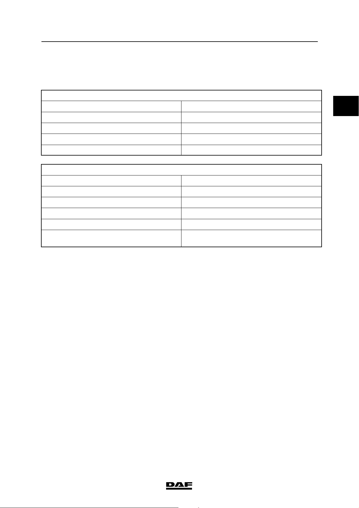
1. SINGLE REAR AXLE 5.10
1.1 GENERAL
Wheel speed sensor
Anti-corrosion agent Molykote P37
Differential attachment stud bolts
Differential attachment stud bolt locking
compound
Pinion gear splines
Sealant Loctite 572
Differential attachment
Sealant between differential and axle housing Loctite 518
Stub axle attachment
Sealant for stub axle flange mating surface Loctite 518
Wheel bearing play
Wheel bearing axial play 0.05 - 0.20 mm
Loctite 2701
1.2 TIGHTENING TORQUES
0
The tightening torques stated in this paragraph
are different from the standard tightening
torques stated in the overview of the standard
tightening torques. The other threaded
connections which are not stated must therefore
be tightened to the tightening torque stated in
the overview of standard tightening torques.
When attachment bolts and nuts are to be
replaced, it is important that these bolts and nuts
are of exactly the same length and property
class as the ones removed - unless stated
otherwise -.
ᓻ 200313
1-1

TECHNICAL DATA
8
Single rear axle 5.10 LF45/55 series
0
Differential
Attachment bolts/nuts 90 Nm
Drainplug 54Nm
Wheel hub
Stub axle attachment nuts 82 Nm
Wheel-speed sensor holder attachment bolts 8 Nm
Lock nut 135 Nm
Level check/filler plug 27 Nm
Notes:
1. Only use a new nut
(1)
1.3 FILLING CAPACITIES
Differential
Filling capacity approx. 4.0 litres
Hub
Filling capacity 0.25 litres
1-2
ᓻ 200313

8
TECHNICAL DATA
LF45/55 series Single rear axle 5.12
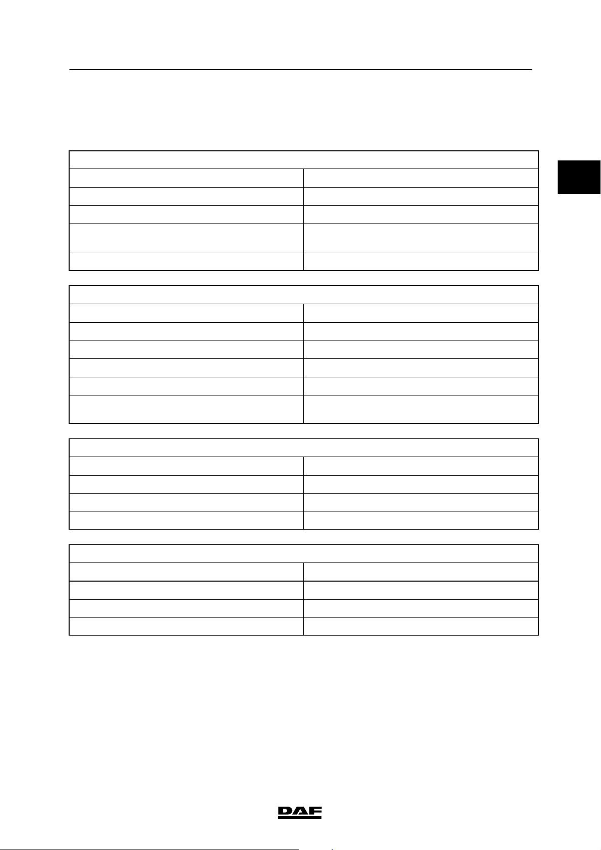
2. SINGLE REAR AXLE 5.12
2.1 GENERAL
Wheel speed sensor
Anti-corrosion agent Molykote P37
Crown wheel guide bolt
Sealant Loctite 572
Differential attachment stud bolts
Differential attachment stud bolt locking
compound
Differential attachment
Sealant between differential and axle housing Loctite 518
Stub axle attachment
Sealant for stub axle flange mating surface Loctite 518
Wheel bearing play
Wheel bearing axial play 0.05 - 0.20 mm
Loctite 2701
2.2 TIGHTENING TORQUES
The tightening torques stated in this paragraph
are different from the standard tightening
torques stated in the overview of the standard
tightening torques. The other threaded
connections which are not stated must therefore
be tightened to the tightening torque stated in
the overview of standard tightening torques.
0
When attachment bolts and nuts are to be
replaced, it is important that these bolts and nuts
are of exactly the same length and property
class as the ones removed - unless stated
otherwise -.
ᓻ 200313
2-1

TECHNICAL DATA
8
Single rear axle 5.12 LF45/55 series
0
Differential
Attachment bolts/nuts 80 Nm
Drive flange attachment nut (self-locking) 675 Nm
Lock nut for crown wheel guide bolt 120 Nm
Drainplug 54Nm
Wheel hub
Stub axle attachment nuts 82 Nm
Wheel-speed sensor holder attachment bolts 8 Nm
Lock nut 135 Nm
Level check/filler plug 27 Nm
Notes:
1. Bolts to be treated with Loctite 572
2. Only use a new nut
(1)
(2)
2.3 FILLING CAPACITIES
Differential
Filling capacity approx. 4.0 litres
Hub
Filling capacity 0.25 litres
2-2
ᓻ 200313

8
TECHNICAL DATA
LF45/55 series Single rear axle 5.14
3. SINGLE REAR AXLE 5.14
3.1 GENERAL
Wheel speed sensor
Anti-corrosion agent Molykote P37
Differential-gear lock stud bolts
Differential-gear lock stud bolt locking
compound
Differential attachment stud bolts
Differential attachment stud bolt locking
compound
Differential attachment
Sealant between differential and axle housing Loctite 518
Stub axle attachment
Sealant for stub axle flange mating surface Loctite 518
Wheel bearing play
Wheel bearing axial play 0.05 - 0.20 mm
Loctite 2701
Loctite 2701
3.2 TIGHTENING TORQUES
0
The tightening torques stated in this paragraph
are different from the standard tightening
torques stated in the overview of the standard
tightening torques. The other threaded
connections which are not stated must therefore
be tightened to the tightening torque stated in
the overview of standard tightening torques.
When attachment bolts and nuts are to be
replaced, it is important that these bolts and nuts
are of exactly the same length and property
class as the ones removed - unless stated
otherwise -.
ᓻ 200313
3-1

TECHNICAL DATA
8
Single rear axle 5.14 LF45/55 series
0
Differential
Differential lock cover attachment bolts 20 Nm
Attachment bolts and nuts 90 Nm
Drive flange attachment nut (self-locking) 675 Nm
Drainplug 54Nm
Wheel hub
Stub axle attachment nuts 82 Nm
Wheel-speed sensor holder attachment bolts 8 Nm
Lock nut 135 Nm
Level check/filler plug 27 Nm
Notes:
1. Bolts to be treated with Loctite 572
2. Only use a new nut
(1)
(1)
(2)
3.3 FILLING CAPACITIES
Differential
Filling capacity approx. 4.0 litres
Hub
Filling capacity 0.25 litres
3-2
ᓻ 200313

8
TECHNICAL DATA
LF45/55 series Single rear axle 8.20
4. SINGLE REAR AXLE 8.20
4.1 GENERAL
Wheel speed sensor
Anti-corrosion agent Molykote P37
Differential-gear lock stud bolts
Differential-gear lock stud bolt locking
compound
Differential attachment stud bolts
Differential attachment stud bolt locking
compound
Differential attachment
Sealant between differential and axle housing Loctite 518
Stub axle attachment
Sealant for stub axle flange mating surface Loctite 518
Wheel bearing play
Wheel bearing axial play 0.05 - 0.20 mm
Loctite 2701
Loctite 2701
4.2 TIGHTENING TORQUES
0
The tightening torques stated in this paragraph
are different from the standard tightening
torques stated in the overview of the standard
tightening torques. The other threaded
connections which are not stated must therefore
be tightened to the tightening torque stated in
the overview of standard tightening torques.
When attachment bolts and nuts are to be
replaced, it is important that these bolts and nuts
are of exactly the same length and property
class as the ones removed - unless stated
otherwise -.
ᓻ 200313
4-1

TECHNICAL DATA
8
Single rear axle 8.20 LF45/55 series
0
Differential
Drive flange attachment nut (self-locking) 675 Nm
Differential lock cover attachment bolts 20 Nm
Attachment bolts/nuts 225 Nm
Drainplug 54Nm
Wheel hub
Stub axle attachment nuts 82 Nm
Wheel-speed sensor holder attachment bolts 8 Nm
Lock nut 135 Nm
Level check/filler plug 27 Nm
Notes:
1. Only use a new nut
2. Bolts to be treated with Loctite 572
(1)
(2)
4.3 FILLING CAPACITIES
Differential
Filling capacity approx. 8.0 litres
Hub
Filling capacity 0.25 litres
4-2
ᓻ 200313

8
TECHNICAL DATA
LF45/55 series Single rear axle 10.20
5. SINGLE REAR AXLE 10.20
5.1 GENERAL
Wheel hub
Before installing the wheel hub, axle journal
to be treated with Gleitmo 805
Wheel speed sensor
Anti-corrosion agent Molykote P37
Differential-gear lock stud bolts
Differential-gear lock stud bolt locking
compound
Differential attachment stud bolts
Differential attachment stud bolt locking
compound
Differential attachment
Sealant between differential and axle housing Loctite 518
Stub axle attachment
Sealant for stub axle flange mating surface Loctite 518
Loctite 2701
Loctite 2701
0
5.2 TIGHTENING TORQUES
The tightening torques stated in this paragraph
are different from the standard tightening
torques stated in the overview of the standard
tightening torques. The other threaded
connections which are not stated must therefore
be tightened to the tightening torque stated in
the overview of standard tightening torques.
When attachment bolts and nuts are to be
replaced, it is important that these bolts and nuts
are of exactly the same length and property
class as the ones removed - unless stated
otherwise -.
ᓻ 200313
5-1

TECHNICAL DATA
8
Single rear axle 10.20 LF45/55 series
0
Differential
Drive flange attachment nut (self-locking) 675 Nm
Differential lock cover attachment bolts 20 Nm
Attachment bolts/nuts 225 Nm
Drainplug 54Nm
Wheel hub
st
-1
-2ndphase turn the hub 10 revolutions at a speed of
-3
-4
-5
Stub axle attachment bolts 260 Nm
Wheel-speed sensor holder attachment bolts 8 Nm
Notes:
1. Only use a new nut
2. Bolts to be treated with Loctite 572
phase 300 Nm
rd
phase 350 Nm
th
phase turn the hub 10 revolutions at a speed of
th
phase 1100 Nm
approx. 40 rpm
approx. 40 rpm
(1)
(2)
(1)
5.3 FILLING CAPACITIES
Differential
Filling capacity approx. 9.0 litres
5-2
ᓻ 200313

8
TECHNICAL DATA
LF45/55 series Single rear axle 10.26
6. SINGLE REAR AXLE 10.26
6.1 GENERAL
Wheel hub
Before installing the wheel hub, axle journal to
be treated with
Wheel speed sensor
Anti-corrosion agent Molykote P37
Differential-gear lock stud bolts
Differential-gear lock stud bolt locking
compound
Differential attachment stud bolts
Differential attachment stud bolt locking
compound
Differential attachment
Sealant between differential and axle housing Loctite 518
Stub axle attachment
Sealant for stub axle flange mating surface Loctite 518
Gleitmo 805
Loctite 2701
Loctite 2701
0
6.2 TIGHTENING TORQUES
The tightening torques stated in this paragraph
are different from the standard tightening
torques stated in the overview of the standard
tightening torques. The other threaded
connections which are not stated must therefore
be tightened to the tightening torque stated in
the overview of standard tightening torques.
When attachment bolts and nuts are to be
replaced, it is important that these bolts and nuts
are of exactly the same length and property
class as the ones removed - unless stated
otherwise.
ᓻ 200313
6-1

TECHNICAL DATA
8
Single rear axle 10.26 LF45/55 series
0
Differential
Drive flange attachment nut (self-locking) 1250 Nm
Differential lock cover attachment bolts 20 Nm
Attachment bolts/nuts 225 Nm
Drainplug 54Nm
Wheel hub
st
-1
-2ndphase turn the hub 10 revolutions at a speed of
-3
-4
-5
Stub axle attachment bolts 260 Nm
Wheel-speed sensor holder attachment bolts 8 Nm
Notes:
1. Only use a new nut
2. Bolts to be treated with Loctite 572
3. Secure with Loctite 262
phase 300 Nm
rd
phase 350 Nm
th
phase turn the hub 10 revolutions at a speed of
th
phase 1100 Nm
approx. 40 rpm
approx. 40 rpm
(1) / (3)
(2)
(1)
6.3 FILLING CAPACITIES
Differential
Filling capacity approx. 9.0 litres
6-2
ᓻ 200313

8
TECHNICAL DATA
LF45/55 series Single rear axle 11.26
7. SINGLE REAR AXLE 11.26
7.1 GENERAL
Wheel hub unit
Before installing the wheel hub unit, axle
journal to be treated with
Wheel speed sensor
Anti-corrosion agent Molykote P37
Differential-gear lock stud bolts
Differential-gear lock stud bolt locking
compound
Differential attachment stud bolts
Differential attachment stud bolt locking
compound
Differential attachment
Sealant between differential and axle housing Loctite 518
Stub axle attachment
Sealant for stub axle flange mating surface Loctite 518
Gleitmo 805
Loctite 2701
Loctite 2701
0
7.2 TIGHTENING TORQUES
The tightening torques stated in this paragraph
are different from the standard tightening
torques stated in the overview of the standard
tightening torques. The other threaded
connections which are not stated must therefore
be tightened to the tightening torque stated in
the overview of standard tightening torques.
When attachment bolts and nuts are to be
replaced, it is important that these bolts and nuts
are of exactly the same length and property
class as the ones removed - unless stated
otherwise.
ᓻ 200313
7-1

TECHNICAL DATA
8
Single rear axle 11.26 LF45/55 series
0
Differential
Drive flange attachment nut 1250 Nm
Differential-gear lock attachment bolts 20 Nm
Attachment bolts/nuts 225 Nm
Drainplug 54Nm
Wheel hub unit
st
-1
-2ndphase turn the hub 10 revolutions at a speed of
-3
-4
-5
Stub axle attachment bolts 260 Nm
Notes:
1. Only fit a new nut and apply Loctite 262 to
2. Bolts to be treated with Loctite 572
3. Only use a new nut
phase 500 Nm
rd
phase 550 Nm
th
phase turn the hub 10 revolutions at a speed of
th
phase 1300 Nm
secure
approx. 40 rpm
approx. 40 rpm
(1) / (3)
(2)
(3)
7.3 FILLING CAPACITIES
Differential
Filling capacity approx. 9.0 litres
7-2
ᓻ 200313

8
DIAGNOSTICS
LF45/55 series Contents
CONTENTS
Page Date
1. SINGLE REAR AXLE 5.10 1-1 200313.............................................. ....
1.1 Fault-finding table 1-1 200313................................................. ....
2. SINGLE REAR AXLE 5.12 2-1 200313.............................................. ....
2.1 Fault-finding table 2-1 200313................................................. ....
3. SINGLE REAR AXLE 5.14 3-1 200313.............................................. ....
3.1 Fault-finding table 3-1 200313................................................. ....
4. SINGLE REAR AXLE 8.20 4-1 200313.............................................. ....
4.1 Fault-finding table 4-1 200313................................................. ....
5. SINGLE REAR AXLE 10.20 5-1 200313............................................. ....
5.1 Fault-finding table 5-1 200313................................................. ....
6. SINGLE REAR AXLE 10.26 6-1 200313............................................. ....
6.1 Fault-finding table 6-1 200313................................................. ....
7. SINGLE REAR AXLE 11.26 7-1 200313............................................. ....
7.1 Fault-finding table 7-1 200313................................................. ....
1
ᓻ 200313
1

1
8DIAGNOSTICS
Contents LF45/55 series
2
ᓻ 200313
8
DIAGNOSTICS
LF45/55 series Single rear axle 5.10
1. SINGLE REAR AXLE 5.10
1.1 FAULT-FINDING TABLE
COMPLAINT: NOISES IN REAR AXLE AND DRIVE ASSEMBLY
Possible cause Remedy
Oil level too low Topupoil
Incorrect oil viscosity Drain oil and top up
Attachment bolts loosened or broken off Drain oil and check drained oil for metal particles
Pinion bearing play Adjust and/or replace
COMPLAINT: OIL LEAK
Possible cause Remedy
Oil level too high Drain oil
Incorrect oil viscosity Drain oil and top up
Leaking oil seal Replace oil seal
Bleeding system blocked Clean or replace the bleeding system
Oil leakage between the differential gear housing
mating surfaces
Clean mating surfaces and apply new sealant
1
ᓻ 200313
1-1

1
DIAGNOSTICS
Single rear axle 5.10 LF45/55 series
8
1-2
ᓻ 200313

8
DIAGNOSTICS
LF45/55 series Single rear axle 5.12
2. SINGLE REAR AXLE 5.12
2.1 FAULT-FINDING TABLE
COMPLAINT: NOISES IN REAR AXLE AND DRIVE ASSEMBLY
Possible cause Remedy
Oil level too low Topupoil
Incorrect oil viscosity Drain oil and top up
Attachment bolts loosened or broken off Drain oil and check drained oil for metal particles
Pinion bearing play Adjust and/or replace
COMPLAINT: OIL LEAK
Possible cause Remedy
Oil level too high Drain oil
Incorrect oil viscosity Drain oil and top up
Leaking oil seal Replace oil seal
Bleeding system blocked Clean or replace the bleeding system
Oil leakage between the differential gear housing
mating surfaces
Clean mating surfaces and apply new sealant
1
ᓻ 200313
2-1

1
DIAGNOSTICS
Single rear axle 5.12 LF45/55 series
8
2-2
ᓻ 200313

8
DIAGNOSTICS
LF45/55 series Single rear axle 5.14
3. SINGLE REAR AXLE 5.14
3.1 FAULT-FINDING TABLE
COMPLAINT: NOISES IN REAR AXLE AND DRIVE ASSEMBLY
Possible cause Remedy
Oil level too low Topupoil
Incorrect oil viscosity Drain oil and top up
Loosened attachment bolts or broken differential
lock parts
Pinion bearing play Adjust and/or replace
COMPLAINT: OIL LEAK
Possible cause Remedy
Oil level too high Drain oil
Incorrect oil viscosity Drain oil and top up
Leaking oil seal Replace oil seal
Bleeding system blocked Clean or replace the bleeding system
Oil leakage between the differential gear housing
mating surfaces
COMPLAINT: DIFFERENTIAL LOCK IS NOT FUNCTIONING
Possible cause Remedy
Drain oil and check drained oil for metal particles
Clean mating surfaces and apply new sealant
1
No air pressure on engaging cylinder Check compressed air system
Defective pneumatic control Check or replace pneumatic switch
Defective mechanical shift control Check shift control
COMPLAINT: DIFFERENTIAL LOCK WARNING LAMP IS NOT FUNCTIONING
Possible cause Remedy
Switch on cylinder fitted too high Readjust switch
Switch on cylinder defective Replace switch
Fault in electrical circuit Check electrical circuit
ᓻ 200313
3-1

1
DIAGNOSTICS
Single rear axle 5.14 LF45/55 series
8
3-2
ᓻ 200313
8
DIAGNOSTICS
LF45/55 series Single rear axle 8.20
4. SINGLE REAR AXLE 8.20
4.1 FAULT-FINDING TABLE
COMPLAINT: NOISES IN REAR AXLE AND DRIVE ASSEMBLY
Possible cause Remedy
Oil level too low Topupoil
Incorrect oil viscosity Drain oil and top up
Loosened attachment bolts or broken differential
lock parts
Pinion bearing play Adjust and/or replace
COMPLAINT: OIL LEAK
Possible cause Remedy
Oil level too high Drain oil
Incorrect oil viscosity Drain oil and top up
Leaking oil seal Replace oil seal
Bleeding system blocked Clean or replace the bleeding system
Oil leakage between the differential gear housing
mating surfaces
COMPLAINT: DIFFERENTIAL LOCK IS NOT FUNCTIONING
Possible cause Remedy
Drain oil and check drained oil for metal particles
Clean mating surfaces and apply new sealant
1
No air pressure on engaging cylinder Check compressed air system
Defective pneumatic control Check or replace pneumatic switch
Defective mechanical shift control Check shift control
COMPLAINT: DIFFERENTIAL LOCK WARNING LAMP IS NOT FUNCTIONING
Possible cause Remedy
Switch on cylinder fitted too high Readjust switch
Switch on cylinder defective Replace switch
Fault in electrical circuit Check electrical circuit
ᓻ 200313
4-1

1
DIAGNOSTICS
Single rear axle 8.20 LF45/55 series
8
4-2
ᓻ 200313

8
DIAGNOSTICS
LF45/55 series Single rear axle 10.20
5. SINGLE REAR AXLE 10.20
5.1 FAULT-FINDING TABLE
COMPLAINT: NOISES IN REAR AXLE AND DRIVE ASSEMBLY
Possible cause Remedy
Oil level too low Topupoil
Incorrect oil viscosity Drain oil and top up
Loosened attachment bolts or broken differential
lock parts
Pinion bearing play Adjust and/or replace
COMPLAINT: OIL LEAK
Possible cause Remedy
Oil level too high Drain oil
Incorrect oil viscosity Drain oil and top up
Leaking oil seal Replace oil seal
Bleeding system blocked Clean or replace the bleeding system
Oil leakage between the differential gear housing
mating surfaces
COMPLAINT: DIFFERENTIAL LOCK IS NOT FUNCTIONING
Possible cause Remedy
Drain oil and check drained oil for metal particles
Clean mating surfaces and apply new sealant
1
No air pressure on engaging cylinder Check compressed air system
Defective pneumatic control Check or replace pneumatic switch
Defective mechanical shift control Check shift control
COMPLAINT: DIFFERENTIAL LOCK WARNING LAMP IS NOT FUNCTIONING
Possible cause Remedy
Switch on cylinder fitted too high Readjust switch
Switch on cylinder defective Replace switch
Fault in electrical circuit Check electrical circuit
ᓻ 200313
5-1

1
DIAGNOSTICS
Single rear axle 10.20 LF45/55 series
8
5-2
ᓻ 200313

8
DIAGNOSTICS
LF45/55 series Single rear axle 10.26
6. SINGLE REAR AXLE 10.26
6.1 FAULT-FINDING TABLE
COMPLAINT: NOISES IN REAR AXLE AND DRIVE ASSEMBLY
Possible cause Remedy
Oil level too low Topupoil
Incorrect oil viscosity Drain oil and top up
Loosened attachment bolts or broken differential
lock parts
Pinion bearing play Adjust and/or replace
COMPLAINT: OIL LEAK
Possible cause Remedy
Oil level too high Drain oil
Incorrect oil viscosity Drain oil and top up
Leaking oil seal Replace oil seal
Bleeding system blocked Clean or replace the bleeding system
Oil leakage between the differential gear housing
mating surfaces
COMPLAINT: DIFFERENTIAL LOCK IS NOT FUNCTIONING
Possible cause Remedy
Drain oil and check drained oil for metal particles
Clean mating surfaces and apply new sealant
1
No air pressure on engaging cylinder Check compressed air system
Defective pneumatic control Check or replace pneumatic switch
Defective mechanical shift control Check shift control
COMPLAINT: DIFFERENTIAL LOCK WARNING LAMP IS NOT FUNCTIONING
Possible cause Remedy
Switch on cylinder fitted too high Readjust switch
Switch on cylinder defective Replace switch
Fault in electrical circuit Check electrical circuit
ᓻ 200313
6-1

1
DIAGNOSTICS
Single rear axle 10.26 LF45/55 series
8
6-2
ᓻ 200313

8
DIAGNOSTICS
LF45/55 series Single rear axle 11.26
7. SINGLE REAR AXLE 11.26
7.1 FAULT-FINDING TABLE
COMPLAINT: NOISES IN REAR AXLE AND DRIVE ASSEMBLY
Possible cause Remedy
Oil level too low Topupoil
Incorrect oil viscosity Drain oil and top up
Loosened attachment bolts or broken differential
lock parts
Pinion bearing play Adjust and/or replace
COMPLAINT: OIL LEAK
Possible cause Remedy
Oil level too high Drain oil
Incorrect oil viscosity Drain oil and top up
Leaking oil seal Replace oil seal
Bleeding system blocked Clean or replace the bleeding system
Oil leakage between the differential gear housing
mating surfaces
COMPLAINT: DIFFERENTIAL LOCK IS NOT FUNCTIONING
Possible cause Remedy
Drain oil and check drained oil for metal particles
Clean mating surfaces and apply new sealant
1
No air pressure on engaging cylinder Check compressed air system
Defective pneumatic control Check or replace pneumatic switch
Defective mechanical shift control Check shift control
COMPLAINT: DIFFERENTIAL LOCK WARNING LAMP IS NOT FUNCTIONING
Possible cause Remedy
Switch on cylinder fitted too high Readjust switch
Switch on cylinder defective Replace switch
Fault in electrical circuit Check electrical circuit
ᓻ 200313
7-1

1
DIAGNOSTICS
Single rear axle 11.26 LF45/55 series
8
7-2
ᓻ 200313

8
SINGLE REAR AXLE 5.10
LF45/55 series Contents
CONTENTS
Page Date
1. SAFETY INSTRUCTIONS 1-1 200313............................................... ....
2. GENERAL 2-1 200313............................................................ ....
2.1 Description of 5.10 axle 2-1 200313............................................ ....
2.2 Overview drawing, wheel hub 2-2 200313....................................... ....
3. INSPECTION AND ADJUSTMENT 3-1 200313....................................... ....
3.1 Inspecting differential oil level 3-1 200313....................................... ....
3.2 Inspection and adjustment, wheel bearing play 3-2 200313........................ ....
3.3 Inspection, wheel-speed sensor ring 3-3 200313................................. ....
4. REMOVAL AND INSTALLATION 4-1 200313........................................ ....
4.1 Removal and installation, stub axles 4-1 200313................................. ....
4.2 Removal and installation, wheel hub 4-2 200313................................. ....
4.3 Removal and installation, hub oil seal 4-4 200313................................ ....
4.4 Removal and installation, wheel bearing 4-4 200313............................. ....
4.5 Removal and installation, wheel-speed sensor 4-5 200313........................ ....
4.6 Removal and installation, drive flange 4-6 200313............................... ....
4.7 Removal and installation, pinion oil seal 4-8 200313.............................. ....
4.8 Removal and installation, differential 4-11 200313................................. ...
2
5. DRAINING AND FILLING 5-1 200313............................................... ....
5.1 Draining and filling, differential 5-1 200313...................................... ....
5.2 Draining and filling, wheel hubs 5-2 200313..................................... ....
ᓻ 200313
1

2
8SINGLE REAR AXLE 5.10
Contents LF45/55 series
2
ᓻ 200313

8
LF45/55 series Safety instructions
SINGLE REAR AXLE 5.10
1. SAFETY INSTRUCTIONS
Always use stands to support the
chassis or components when
working under the vehicle.
Always use the appropriate lifting
gear or approved hoists to remove
and install heavy components.
Attach the component securely to
the lifting or hoisting gear.
2
ᓻ 200313
1-1

2
SINGLE REAR AXLE 5.10
Safety instructions LF45/55 series
8
1-2
ᓻ 200313

8
SINGLE REAR AXLE 5.10
LF45/55 series General
2. GENERAL
2.1 DESCRIPTION OF 5.10 AXLE
Differential
The 5.10 axle has a differential with hypoid
gearing.
A single reduction is applied.
The bevelled gear-to-pinion backlash is
achieved using adjusting nuts.
The pre-load of the pinion bearings for the 5.10
axle is adjusted using a pre-load bush which is
placed between the pinion and the inner race of
the front bearing.
Wheel hub
The wheel hub has a wheel bearing and hub oil
seal that can be replaced separately. The
wheel-speed sensor ring is integrated into the
wheel hub. The wheel bearing play is adjusted
using the hub nut. The correct wheel bearing
pre-load is achieved by fitting the hub nut as
specified.
The hub nut is secured with a lock nut and a
locking plate.
The wheel bearing is greased by the oil in the
hub.
The stub axle and brake disc are attached to the
wheel hub with attachment nuts and bolts
respectively.
2
ᓻ 200313
2-1

;;;
;;;
;;;
;;;
;
;
2
SINGLE REAR AXLE 5.10
8
General LF45/55 series
2.2 OVERVIEW DRAWING, WHEEL HUB
1 2 3 4 5 6 7 8 9 10 11 12 13
Legend
1. Stub axle
2. Lock nut
3. Locking plate
4. Hub nut
5. Thrust washer
6. Wheel bearing inner race
7. Wheel bearing outer race
8. Wheel stud
9. Wheel hub
14151617
10. Hub oil seal
11. Wheel-speed sensor holder attachment
bolts
12. Wheel-speed sensor holder
13. Wheel-speed sensor
14. Brake disc
15. Brake disc attachment bolt
16. Drain plug
17. Stub axle attachment nut
A8 00 384
2-2
ᓻ 200313

8
SINGLE REAR AXLE 5.10
LF45/55 series Inspection and adjustment
3. INSPECTION AND ADJUSTMENT
3.1 INSPECTING DIFFERENTIAL OIL LEVEL
To prevent skin injury, avoid
unnecessary contact with the
drained oil.
1. Position the vehicle on a level surface.
2. Remove the level check/filler plug (1). The
oil level must reach the level check/filler
opening (1).
3. Apply sealant to the plug. Secure the plug.
2
1
A8 00 375
ᓻ 200313
3-1

2
SINGLE REAR AXLE 5.10
8
Inspection and adjustment LF45/55 series
3.2 INSPECTION AND ADJUSTMENT, WHEEL BEARING PLAY
Inspecting the wheel bearing play
1. Remove the wheel.
2. Remove the stub axle.
3. Remove the brake pads.
4. Fit a micrometer gauge to the wheel hub,
with the stylus on the end of the axle
journal.
5. Push and pull the wheel hub. Check the
wheel bearing play and compare it with the
specified value. See main group “Technical
data”.
A8 00 387
Adjusting the wheel bearing play
1. Remove the lock nut.
2. Tighten the hub nut with a hub nut wrench
(DAF No. 0499805) to 136 Nm.
3. Turn the hub two full rotations in order to
“seat” the wheel bearings.
4. Mark (1) the hub nut wrench (2).
5. Turn the hub nut 2 strokes back.
6. Check the wheel bearing play.
7. Position the locking plate and fit the lock
nut. Tighten the lock nut to the specified
tightening torque. See main group
“Technical data”.
8. Secure the hub nut and lock nut with the
locking plate.
1
2
1
3-2
A8 00 380
ᓻ 200313

8
SINGLE REAR AXLE 5.10
LF45/55 series Inspection and adjustment
3.3 INSPECTION, WHEEL-SPEED SENSOR RING
1. Check the sensor ring (2) for deposits.
Special attention should be paid to deposits
between the teeth of the sensor ring.
Clean the sensor ring if necessary.
2
2. Check the sensor ring (2) for damage. Even
the slightest damage may cause a failure.
If necessary, replace the wheel hub.
3. Check the sensor (1) for smooth operation.
If necessary, clean the sensor (1) and
re-apply the specified anti-corrosion agent.
See main group “Technical data”.
Never tap the sensor with a
hammer. This may damage both the
sensor and the sensor ring.
4. Check the ABS system for proper operation.
1
2
A8 00 391
ᓻ 200313
3-3

2
SINGLE REAR AXLE 5.10
Inspection and adjustment LF45/55 series
8
3-4
ᓻ 200313

8
SINGLE REAR AXLE 5.10
LF45/55 series Removal and installation
4. REMOVAL AND INSTALLATION
4.1 REMOVAL AND INSTALLATION, STUB AXLES
Removing stub axles
1. Jack up the rear axle and support it on
stands.
2. Remove the stub axle attachment nuts.
3. Remove the stub axle using a copper
punch. When the stub axle comes loose, a
small amount of oil may leak out. Collect
this oil.
Installing stub axles
1. Clean the mating surfaces of the stub axle
flange and wheel hub.
2. Apply the specified sealant to the mating
surface of the stub axle flange. See main
group “Technical data”.
3. Fit the stub axle. Tighten the stub axle
attachment nuts to the specified tightening
torque. See main group “Technical data”.
2
ᓻ 200313
4-1

2
SINGLE REAR AXLE 5.10
8
Removal and installation LF45/55 series
4.2 REMOVAL AND INSTALLATION, WHEEL HUB
Removing wheel hub
7
4
3
1
2
9
8
6
5
1. Jack up the rear axle and support it on
stands.
2. Remove the wheels.
3. Remove the brake caliper.
4. Remove the stub axle (1).
5. Remove the lock nut (2).
6. Remove the locking plate (3).
7. Remove the hub nut (4).
8. Remove the thrust washer (5).
9. Remove the wheel bearing inner race (6).
10. Remove the wheel hub from the axle
journal.
A8 00 394
4-2
ᓻ 200313

8
SINGLE REAR AXLE 5.10
LF45/55 series Removal and installation
Installing wheel hub
1. Check the wheel-speed sensor ring and the
oil seal in the wheel hub for damage.
Replace the oil seal if in doubt.
2. Check the axle journal screw thread
carefully for damage.
3. Install the wheel hub on the axle journal.
Slide the wheel hub onto the axle journal.
Fit the wheel bearing inner race (6).
4. Fit the thrust washer (5).
5. Fit the hub nut (4).
6. Adjust the wheel bearing play, see chapter
“Inspection and adjustment”.
7. Fit the locking plate (3).
8. Fit the lock nut (2). Tighten the lock nut (2)
to the specified tightening torque. See main
group “Technical data”.
2
9. Secure the lock nut (2) with the locking
plate (3).
10. Press the wheel-speed sensor (1) against
the sensor ring (2). When the vehicle is
being driven, the air gap between the
sensor and the sensor ring is adjusted
automatically.
If the sensor is stuck, remove, clean and
refit it.
Never tap the sensor with a
hammer. This may damage both the
sensor and the sensor ring.
11. Fit the stub axle.
12. Fit the brake caliper.
13. Put the wheels back on.
14. Check the ABS system for proper operation.
2
1
A8 00 391
ᓻ 200313
4-3

2
SINGLE REAR AXLE 5.10
8
Removal and installation LF45/55 series
4.3 REMOVAL AND INSTALLATION, HUB OIL SEAL
Removing hub oil seal
1. Remove the wheel hub from the axle
journal.
2. Drill two holes into the oil seal and screw
the special tool (B) (DAF No. 0484899) into
the oil seal. Pull the oil seal from the pinion
housing using the special tool (A)
(DAF No. 0694928).
Installing hub oil seal
1. Use the special tool (DAF No. 0499809) to
fit the oil seal such that the marking
“outside” is pointing outward.
2. Install the wheel hub.
A
4.4 REMOVAL AND INSTALLATION, WHEEL BEARING
Removing wheel bearing
1. Remove the wheel hub.
2. Remove the oil seal from the wheel hub.
3. There are recesses in the wheel hub for
removing the wheel bearing outer race.
4. Remove the wheel bearing outer races from
the wheel hub using a driver.
Installing wheel bearing
1. Fit the wheel bearing outer races in the
wheel hub using a driver.
B
A8 00 392
2. Fit the hub oil seal.
3. Install the wheel hub.
4-4
A8 00 393
ᓻ 200313

8
SINGLE REAR AXLE 5.10
LF45/55 series Removal and installation
4.5 REMOVAL AND INSTALLATION, WHEEL-SPEED SENSOR
Removing the wheel-speed sensor
1. Remove the wheel-speed sensor (1) from
the holder (3).
2. Cut the clamping strips attaching the cable.
3. Unplug the connector and remove the
wheel-speed sensor.
1
2
3
Installing the wheel-speed sensor
1. Clean the wheel-speed sensor (1) and the
clamping sleeve (2). If necessary, replace
theclampingsleeve(2).
2. Apply the specified anti-corrosion agent to
the circumference of the wheel-speed
sensor (1). See main group “Technical
data”.
3. Fit the wheel-speed sensor (1) in the holder
(3). Press it against the sensor ring
manually.
While the vehicle is being driven, the air gap
between the sensor and the sensor ring is
adjusted automatically.
Never tap the sensor with a
hammer. This may damage both the
sensor and the sensor ring.
4. Fit the connector and secure the cable with
clamping strips.
5. Check the ABS system for proper operation.
2
A8 00 435
ᓻ 200313
4-5

SINGLE REAR AXLE 5.10
8
Removal and installation LF45/55 series
4.6 REMOVAL AND INSTALLATION, DRIVE FLANGE
Removing drive flange
1. Remove the prop shaft from the drive
flange.
2. Jack up the rear axle and support it on
stands.
3. Remove the stub axles.
2
4. Determine the pre-load of the pinion
bearings by turning the drive flange nut
using a torque wrench with a dial (2) and a
12-sided socket (1). Write down the
measured slip torque.
5. Fit the special tool (B) (DAF No. 0484977)
on the drive flange to prevent it from
turning. Remove the drive flange nut using
a 12-sided socket and a torque
amplifier (A).
1
2
A8 00 442
A B
6. Remove the drive flange. If necessary, use
a puller.
Installing drive flange
1. Check the dust seal ring of the drive flange.
If required, replace the dust seal ring.
2. Check the drive flange at the oil-seal
running surface for grooves and/or sharp
edges. If required, replace the drive flange.
3. Clean the splines of the pinion and drive
flange.
4-6
A8 00 386
ᓻ 200313

8
SINGLE REAR AXLE 5.10
LF45/55 series Removal and installation
4. Apply the specified sealant to the splines of
the pinion. See main group “Technical data”.
5. Fit the drive flange.
6. Fit a new drive flange nut.
7. Fit the special tool (3) (DAF No. 0484977)
to the drive flange to prevent it from turning.
Tighten the drive flange nut using a
12-sided socket and a torque amplifier (A)
until no play is noticeable on the pinion.
8. Turn the drive flange a number of times to
“seat” the pinion bearings.
9. Tighten the drive flange until the slip torque
of the drive flange nut exceeds the noted
valueby0.4-0.6Nm.
Note:
If the slip torque of the drive flange nut
exceeds the noted value increased by
0.4 - 0.6 Nm, loosen the drive flange nut a
few strokes and repeat the setting
procedure.
10. Fit the stub axles.
11. Fit the prop shaft to the drive flange.
A B
2
A8 00 386
ᓻ 200313
4-7

SINGLE REAR AXLE 5.10
8
Removal and installation LF45/55 series
4.7 REMOVAL AND INSTALLATION, PINION OIL SEAL
Removing pinion oil seal
1. Remove the prop shaft from the drive
flange.
2. Jack up the rear axle and support it on
stands.
3. Remove the stub axles.
2
4. Determine the pre-load of the pinion
bearings by turning the drive flange nut
using a torque wrench with a dial (2) and a
12-sided socket (1). Write down the
measured slip torque.
5. Fit the special tool (B) (DAF No. 0484977)
on the drive flange to prevent it from
turning. Remove the drive flange nut using
a 12-sided socket and a torque
amplifier (A).
1
2
A8 00 442
A B
6. Remove the drive flange. If necessary, use
a puller.
4-8
A8 00 386
ᓻ 200313

8
SINGLE REAR AXLE 5.10
LF45/55 series Removal and installation
7. Remove the oil seal (1) from the differential
housing.
1
A8 00 441
Installing pinion oil seal
1. Use the special tool (DAF No. 1453141) to
fit the oil seal. Make sure that the steel
outer ring of the oil seal abuts fully against
the differential housing.
2
2. Check the dust seal ring of the drive flange.
If required, replace the dust seal ring.
3. Check the drive flange at the oil seal
running surface for grooves and/or sharp
edges. If required, replace the drive flange.
4. Clean the splines of the pinion and drive
flange.
5. Apply the specified sealant to the splines of
the pinion. See main group “Technical data”.
6. Fit the drive flange.
7. Fit a new drive flange nut.
ᓻ 200313
4-9

SINGLE REAR AXLE 5.10
8
Removal and installation LF45/55 series
2
8. Fit the special tool (B) (DAF No. 0484977)
on the drive flange to prevent it from
turning. Tighten the drive flange nut using a
12-sided socket and a torque amplifier (A)
until no play is noticeable on the pinion.
9. Turn the drive flange a number of times to
“seat” the pinion bearings.
10. Tighten the drive flange until the slip torque
of the drive flange nut exceeds the noted
valueby0.4-0.6Nm.
Note:
If the slip torque of the drive flange nut
exceeds the noted value increased by
0.4 - 0.6 Nm, loosen the drive flange nut a
few strokes and repeat the setting
procedure.
11. Fit the stub axles.
12. Fit the prop shaft to the drive flange.
A B
A8 00 386
4-10
ᓻ 200313

8
SINGLE REAR AXLE 5.10
LF45/55 series Removal and installation
4.8 REMOVAL AND INSTALLATION, DIFFERENTIAL
Removing differential
1. Drain the oil from the differential. See
chapter “Draining and filling”.
2. Remove the prop shaft from the drive
flange.
3. Remove the stub axles.
4. Attach the differential securely to a lifting
device.
5. Remove the attachment bolts and nuts from
the differential.
6. Remove the differential from the axle
housing by carefully pressing the differential
off the axle housing using a pry bar at the
indicated places.
Installing differential
1. Clean the mating surfaces of the axle
housing and the differential housing.
Regrind the mating faces lightly. Do not
damage the mating faces in the process.
2. Clean and degrease the bolts. Check the
bolts and stud bolts for signs of damage.
3. Apply a thin, even layer of sealant to the
mating surface and around the bolt holes of
the axle housing.
4. Apply locking compound to the attachment
bolts. See main group “Technical data”.
5. Fit the differential into the axle housing. Fit
the attachment bolts and nuts and tighten
them evenly. Tighten the attachment bolts
and nuts to the specified tightening torque.
See “Technical data”.
2
A8 00 440
6. Fit the stub axles.
7. Fit the prop shaft to the drive flange.
8. Fill the differential with oil. See chapter
“Draining and filling”.
ᓻ 200313
4-11

2
SINGLE REAR AXLE 5.10
Removal and installation LF45/55 series
8
4-12
ᓻ 200313

8
SINGLE REAR AXLE 5.10
LF45/55 series Draining and filling
5. DRAINING AND FILLING
5.1 DRAINING AND FILLING, DIFFERENTIAL
To prevent skin injury, avoid
unnecessary contact with the
drained oil.
Draining the differential
1. Position the vehicle on a level surface.
2. Place a suitable tray beneath the differential
to collect the oil.
3. Remove the drain plug (1) and the level
check/filler plug (2). Drain the oil.
4. Apply sealant to the screw thread of the
drain plug (1). Install the drain plug (1) and
tighten it to the specified tightening torque.
See main group “Technical data”.
Filling the differential
1. Fill the differential via the level check/filler
plug (2) with the specified and correct
quantity of oil. See main group “Technical
data”.
2
2
2. Check the oil level after 5 minutes; it should
reach up to the level check/filler plug (2).
3. Apply sealant to the screw thread of the
level check/filler plug (2). Fit the level
check/filler plug (2).
1
A8 00 370
ᓻ 200313
5-1

2
SINGLE REAR AXLE 5.10
8
Draining and filling LF45/55 series
5.2 DRAINING AND FILLING, WHEEL HUBS
To prevent skin injury, avoid
unnecessary contact with the
drained oil.
Note:
The design of the hub and the location of the
drain/filler plug may differ from the illustration,
depending on the version.
Draining wheel hub
1. Position the vehicle on a level surface.
2. Position the wheels in such a way that the
oil drain/filler plug (1) is at the bottom.
3. Place a suitable tray under the hub to
collect the oil. Remove the oil drain/filler
plug (1).
4. Drain the oil and let the oil leak out of the
hub.
Filling wheel hub
1. Position the wheels in such a way that the
oil drain/filler plug (1) is at the top.
2. Fill the wheel hub with the specified and
correct quantity of oil. See main group
“Technical data”.
3. Apply sealant to the screw thread of the oil
drain/filler plug (1). Fit the oil drain/filler plug
(1) into the hub.
1
A8 00 369
5-2
ᓻ 200313

8
SINGLE REAR AXLE 5.12
LF45/55 series Contents
CONTENTS
Page Date
1. SAFETY INSTRUCTIONS 1-1 200313............................................... ....
2. GENERAL 2-1 200313............................................................ ....
2.1 Description of 5.12 axle 2-1 200313............................................ ....
2.2 Overview drawing, wheel hub 2-2 200313....................................... ....
3. INSPECTION AND ADJUSTMENT 3-1 200313....................................... ....
3.1 Inspecting differential oil level 3-1 200313....................................... ....
3.2 Adjusting the crown wheel guide bolt 3-2 200313................................ ....
3.3 Inspection and adjustment, wheel bearing play 3-3 200313........................ ....
3.4 Inspection, wheel-speed sensor ring 3-4 200313................................. ....
4. REMOVAL AND INSTALLATION 4-1 200313........................................ ....
4.1 Removal and installation, stub axles 4-1 200313................................. ....
4.2 Removal and installation, wheel hub 4-2 200313................................. ....
4.3 Removal and installation, hub oil seal 4-4 200313................................ ....
4.4 Removal and installation, wheel bearing 4-4 200313............................. ....
4.5 Removal and installation, wheel-speed sensor 4-5 200313........................ ....
4.6 Removal and installation, drive flange 4-6 200313............................... ....
4.7 Removal and installation, pinion oil seal 4-7 200313.............................. ....
4.8 Removal and installation, differential 4-8 200313................................. ....
3
5. DRAINING AND FILLING 5-1 200313............................................... ....
5.1 Draining and filling, differential 5-1 200313...................................... ....
5.2 Draining and filling, wheel hubs 5-2 200313..................................... ....
ᓻ 200313
1

3
8SINGLE REAR AXLE 5.12
Contents LF45/55 series
2
ᓻ 200313

8
LF45/55 series Safety instructions
SINGLE REAR AXLE 5.12
1. SAFETY INSTRUCTIONS
Always use stands to support the
chassis or components when
working under the vehicle.
Always use the appropriate lifting
gear or approved hoists to remove
and install heavy components.
Attach the component securely to
the lifting or hoisting gear.
3
ᓻ 200313
1-1

3
SINGLE REAR AXLE 5.12
Safety instructions LF45/55 series
8
1-2
ᓻ 200313

8
SINGLE REAR AXLE 5.12
LF45/55 series General
2. GENERAL
2.1 DESCRIPTION OF 5.12 AXLE
Differential
The 5.12 axle has a differential with hypoid
gearing.
A single reduction is applied.
The bevelled gear-to-pinion backlash is
achieved using adjusting nuts.
The pre-load of the pinion bearings for the 5.12
axle is adjusted using shims which are placed
between the bearing inner races.
The pinion housing of the 5.12 axle can be
removed using jacking bolts.
Wheel hub
The wheel hub has a wheel bearing and hub oil
seal that can be replaced separately. The
wheel-speed sensor ring is integrated into the
wheel hub. The wheel bearing play is adjusted
using the hub nut. The correct wheel bearing
pre-load is achieved by fitting the hub nut as
specified.
The hub nut is secured with a lock nut and a
locking plate.
The wheel bearing is greased by the oil in the
hub.
The stub axle and brake disc are attached to the
wheel hub with attachment nuts and bolts
respectively.
3
ᓻ 200313
2-1

;;;
;;;
;;;
;;;
;
;
3
SINGLE REAR AXLE 5.12
8
General LF45/55 series
2.2 OVERVIEW DRAWING, WHEEL HUB
1 2 3 4 5 6 7 8 9 10 11 12 13
Legend
1. Stub axle
2. Lock nut
3. Locking plate
4. Hub nut
5. Thrust washer
6. Wheel bearing inner race
7. Wheel bearing outer race
8. Wheel stud
9. Wheel hub
14151617
10. Hub oil seal
11. Wheel-speed sensor holder
12. Wheel-speed sensor holder attachment
bolts
13. Wheel-speed sensor
14. Brake disc
15. Brake disc attachment bolt
16. Drain plug
17. Stub axle attachment nut
A8 00 384
2-2
ᓻ 200313

8
SINGLE REAR AXLE 5.12
LF45/55 series Inspection and adjustment
3. INSPECTION AND ADJUSTMENT
3.1 INSPECTING DIFFERENTIAL OIL LEVEL
To prevent skin injury, avoid
unnecessary contact with the
drained oil.
1. Position the vehicle on a level surface.
2. Remove the level check/filler plug (1). The
oil level must reach the level check/filler
opening (1).
3. Apply sealant to the plug. Secure the plug.
3
1
A8 00 375
ᓻ 200313
3-1

SINGLE REAR AXLE 5.12
8
Inspection and adjustment LF45/55 series
3.2 ADJUSTING THE CROWN WHEEL GUIDE BOLT
1. Place chocks in front of the wheels and
engage the parking brake.
2. Loosen the lock ring (1) and loosen the lock
nut (2) a few turns.
3. Remove the adjusting screw (3) from the
differential.
3
2
3
4. Remove the lock ring (1).
5. Remove any residual sealant from the
adjusting screw and apply new sealant to
the last 4 windings of the screw thread. See
main group “Technical data”.
6. Fit the adjusting screw with a new lock ring
and tighten the adjusting screw against the
crown wheel.
7. Turn the adjusting screw 1/8 stroke back to
obtain the required play A.
8. Tighten the lock nut to the specified
tightening torque. See main group
“Technical data”.
Note:
Make sure that the adjusting screw does not
turn while the lock nut is being tightened.
9. Secure the lock nut by folding the lips of the
lock ring.
1
A8 00 429
3-2
ᓻ 200313

8
SINGLE REAR AXLE 5.12
LF45/55 series Inspection and adjustment
3.3 INSPECTION AND ADJUSTMENT, WHEEL BEARING PLAY
Inspecting the wheel bearing play
1. Remove the wheel.
2. Remove the stub axle.
3. Remove the brake pads.
4. Fit a micrometer gauge to the wheel hub,
with the stylus on the end of the axle
journal.
5. Push and pull the wheel hub. Check the
wheel bearing play and compare it with the
specified value. See main group “Technical
data”.
A8 00 387
3
Adjusting the wheel bearing play
1. Remove the lock nut.
2. Tighten the hub nut with a hub nut wrench
(DAF No. 0499805) to 136 Nm.
3. Turn the hub two full rotations in order to
“seat” the wheel bearings.
4. Mark (1) the hub nut wrench (2).
5. Turn the hub nut 2 strokes back.
6. Check the wheel bearing play.
7. Position the locking plate and fit the lock
nut. Tighten the lock nut to the specified
tightening torque. See main group
“Technical data”.
8. Secure the hub nut and lock nut with the
locking plate.
1
2
1
ᓻ 200313
A8 00 380
3-3

SINGLE REAR AXLE 5.12
8
Inspection and adjustment LF45/55 series
3.4 INSPECTION, WHEEL-SPEED SENSOR RING
1. Check the sensor ring (2) for deposits.
Special attention should be paid to deposits
between the teeth of the sensor ring.
Clean the sensor ring if necessary.
2
3
2. Check the sensor ring (2) for damage. Even
the slightest damage may cause a failure.
If necessary, replace the wheel hub.
3. Check the sensor (1) for smooth operation.
If necessary, clean the sensor (1) and
re-apply the specified anti-corrosion agent.
See main group “Technical data”.
Never tap the sensor with a
hammer. This may damage both the
sensor and the sensor ring.
4. Check the ABS system for proper operation.
1
A8 00 391
3-4
ᓻ 200313

8
SINGLE REAR AXLE 5.12
LF45/55 series Removal and installation
4. REMOVAL AND INSTALLATION
4.1 REMOVAL AND INSTALLATION, STUB AXLES
Removing stub axles
1. Jack up the rear axle and support it on
stands.
2. Remove the stub axle attachment nuts.
3. Remove the stub axle using a copper
punch. When the stub axle comes loose, a
small amount of oil may leak out. Collect
this oil.
Installing stub axles
1. Clean the mating surfaces of the stub axle
flange and wheel hub.
2. Apply the specified sealant to the mating
surface of the stub axle flange. See main
group “Technical data”.
3. Fit the stub axle. Tighten the stub axle
attachment nuts to the specified tightening
torque. See main group “Technical data”.
3
ᓻ 200313
4-1

3
SINGLE REAR AXLE 5.12
8
Removal and installation LF45/55 series
4.2 REMOVAL AND INSTALLATION, WHEEL HUB
Removing wheel hub
7
4
3
1
2
9
8
6
5
1. Jack up the rear axle and support it on
stands.
2. Remove the wheels.
3. Remove the brake caliper.
4. Remove the stub axle (1).
5. Remove the lock nut (2).
6. Remove the locking plate (3).
7. Remove the hub nut (4).
8. Remove the thrust washer (5).
9. Remove the wheel bearing inner race (6).
10. Remove the wheel hub from the axle
journal.
A8 00 394
4-2
ᓻ 200313

8
SINGLE REAR AXLE 5.12
LF45/55 series Removal and installation
Installing wheel hub
1. Check the wheel-speed sensor ring and the
oil seal in the wheel hub for damage.
Replace the oil seal if in doubt.
2. Check the axle journal screw thread
carefully for damage.
3. Install the wheel hub on the axle journal.
Slide the wheel hub onto the axle journal.
Fit the wheel bearing inner race (6).
4. Fit the thrust washer (5).
5. Fit the hub nut (4).
6. Adjust the wheel bearing play, see chapter
“Inspection and adjustment”.
7. Fit the locking plate (3).
8. Fit the lock nut (2). Tighten the lock nut (2)
to the specified tightening torque. See main
group “Technical data”.
9. Secure the lock nut (2) with the locking
plate (3).
10. Press the wheel-speed sensor (1) against
the sensor ring (2). When the vehicle is
being driven, the air gap between the
sensor and the sensor ring is adjusted
automatically.
If the sensor is stuck, remove, clean and
refit it.
Never tap the sensor with a
hammer. This may damage both the
sensor and the sensor ring.
11. Fit the stub axle.
12. Fit the brake caliper.
13. Put the wheels back on.
3
2
1
A8 00 391
14. Check the ABS system for proper operation.
ᓻ 200313
4-3

3
SINGLE REAR AXLE 5.12
8
Removal and installation LF45/55 series
4.3 REMOVAL AND INSTALLATION, HUB OIL SEAL
Removing hub oil seal
1. Remove the wheel hub from the axle
journal.
2. Drill two holes into the oil seal and screw
the special tool (B) (DAF No. 0484899) into
the oil seal. Pull the oil seal from the pinion
housing using the special tool (A)
(DAF No. 0694928).
Installing hub oil seal
1. Use the special tool (DAF No. 0499809) to
fit the oil seal such that the marking
“outside” is pointing outward.
2. Install the wheel hub.
A
B
4.4 REMOVAL AND INSTALLATION, WHEEL BEARING
Removing wheel bearing
1. Remove the wheel hub.
2. Remove the oil seal from the wheel hub.
3. There are recesses in the wheel hub for
removing the wheel bearing outer race.
4. Remove the wheel bearing outer races from
the wheel hub using a driver.
Installing wheel bearing
1. Fit the wheel bearing outer races in the
wheel hub using a driver.
2. Fit the hub oil seal.
3. Install the wheel hub.
A8 00 392
A8 00 393
4-4
ᓻ 200313

8
SINGLE REAR AXLE 5.12
LF45/55 series Removal and installation
4.5 REMOVAL AND INSTALLATION, WHEEL-SPEED SENSOR
Removing the wheel-speed sensor
1. Remove the wheel-speed sensor (1) from
the holder (3).
2. Cut the clamping strips attaching the cable.
3. Unplug the connector and remove the
wheel-speed sensor.
Installing the wheel-speed sensor
1. Clean the wheel-speed sensor (1) and the
clamping sleeve (2). If necessary, replace
theclampingsleeve(2).
2. Apply the specified anti-corrosion agent to
the circumference of the wheel-speed
sensor (1). See main group “Technical
data”.
3. Fit the wheel-speed sensor (1) in the holder
(3). Press it against the sensor ring
manually.
While the vehicle is being driven, the air gap
between the sensor and the sensor ring is
adjusted automatically.
1
2
3
A8 00 435
3
Never tap the sensor with a
hammer. This may damage both the
sensor and the sensor ring.
4. Fit the connector and secure the cable with
clamping strips.
5. Check the ABS system for proper operation.
ᓻ 200313
4-5

SINGLE REAR AXLE 5.12
8
Removal and installation LF45/55 series
4.6 REMOVAL AND INSTALLATION, DRIVE FLANGE
Removing drive flange
1. Remove the prop shaft from the drive
flange.
3
2. Fit the special tool (B) (DAF No. 0484977)
on the drive flange to prevent it from
turning. Remove the drive flange nut using
a torque amplifier (A).
3. Remove the drive flange. If necessary, use
a puller.
Installing drive flange
1. Before installation check the drive flange
along the oil-seal running surface for
grooves and/or sharp edges. If required,
replace the drive flange.
2. Fit the drive flange.
3. Apply a small amount of oil to the abutting
surface of the drive flange nut.
4. Fit a new drive flange nut.
5. Fit the special tool (B) (DAF No. 0484977)
on the drive flange to prevent it from
turning. Use a torque amplifier (A) to tighten
the drive flange nut to the specified
tightening torque. See main group
“Technical data”.
6. Fit the prop shaft to the drive flange.
A B
A8 00 386
4-6
ᓻ 200313

8
SINGLE REAR AXLE 5.12
LF45/55 series Removal and installation
4.7 REMOVAL AND INSTALLATION, PINION OIL SEAL
Removing pinion oil seal
1. Remove the drive flange.
2. Drill two holes into the oil seal and screw
the special tool (B) (DAF No. 0484899) into
the oil seal. Pull the oil seal from the pinion
housing using the special tool (A)
(DAF No. 0694928).
Installing pinion oil seal
1. Use the special tool (DAF No. 0485183) to
fit the oil seal such that the marking
“outside” is pointing outward.
2. Fit the drive flange.
A
B
3
A8 00 381
ᓻ 200313
4-7

3
SINGLE REAR AXLE 5.12
8
Removal and installation LF45/55 series
4.8 REMOVAL AND INSTALLATION, DIFFERENTIAL
Removing differential
1. Drain the oil from the differential. See
chapter “Draining and filling”.
2. Remove the prop shaft from the drive
flange.
3. Remove the stub axles.
4. Attach the differential securely to a lifting
device.
5. Remove the attachment bolts and nuts from
the differential.
6. Remove the differential from the axle
housing using two thrust bolts.
Installing differential
1. Clean the mating surfaces of the axle
housing and the differential housing.
Regrind the mating faces lightly. Do not
damage the mating faces in the process.
2. Clean and degrease the bolts. Check the
bolts and stud bolts for signs of damage.
3. Apply a thin, even layer of sealant to the
mating surface and around the bolt holes of
the axle housing.
4. Apply locking compound to the attachment
bolts. See main group “Technical data”.
5. Fit the differential into the axle housing. Fit
the attachment bolts and nuts and tighten
them evenly. Tighten the attachment bolts
and nuts to the specified tightening torque.
See “Technical data”.
6. Fit the stub axles.
7. Fit the prop shaft to the drive flange.
8. Fill the differential with oil. See chapter
“Draining and filling”.
A8 00 378
4-8
ᓻ 200313

8
SINGLE REAR AXLE 5.12
LF45/55 series Draining and filling
5. DRAINING AND FILLING
5.1 DRAINING AND FILLING, DIFFERENTIAL
To prevent skin injury, avoid
unnecessary contact with the
drained oil.
Draining the differential
1. Position the vehicle on a level surface.
2. Place a suitable tray beneath the differential
to collect the oil.
3. Remove the drain plug (1) and the level
check/filler plug (2). Drain the oil.
4. Apply sealant to the screw thread of the
drain plug (1). Install the drain plug (1) and
tighten it to the specified tightening torque.
See main group “Technical data”.
Filling the differential
1. Fill the differential via the level check/filler
plug (2) with the specified and correct
quantity of oil. See main group “Technical
data”.
2. Check the oil level after 5 minutes; it should
reach up to the level check/filler plug (2).
3. Apply sealant to the screw thread of the
level check/filler plug (2). Fit the level
check/filler plug (2).
3
2
1
A8 00 370
ᓻ 200313
5-1

SINGLE REAR AXLE 5.12
8
Draining and filling LF45/55 series
5.2 DRAINING AND FILLING, WHEEL HUBS
To prevent skin injury, avoid
unnecessary contact with the
drained oil.
Note:
The design of the hub and the location of the
drain/filler plug may differ from the illustration,
depending on the version.
Draining wheel hub
1. Position the vehicle on a level surface.
3
2. Position the wheels in such a way that the
oil drain/filler plug (1) is at the bottom.
3. Place a suitable tray under the hub to
collect the oil. Remove the oil drain/filler
plug (1).
4. Drain the oil and let the oil leak out of the
hub.
Filling wheel hub
1. Position the wheels in such a way that the
oil drain/filler plug (1) is at the top.
2. Fill the wheel hub with the specified and
correct quantity of oil. See main group
“Technical data”.
3. Apply sealant to the screw thread of the oil
drain/filler plug (1). Fit the oil drain/filler plug
(1) into the hub.
1
5-2
A8 00 369
ᓻ 200313

8
SINGLE REAR AXLE 5.14
LF45/55 series Contents
CONTENTS
Page Date
1. SAFETY INSTRUCTIONS 1-1 200313............................................... ....
2. GENERAL 2-1 200313............................................................ ....
2.1 Description of 5.14 axle 2-1 200313............................................ ....
2.2 Overview drawing, wheel hub 2-3 200313....................................... ....
3. INSPECTION AND ADJUSTMENT 3-1 200313....................................... ....
3.1 Inspecting differential oil level 3-1 200313....................................... ....
3.2 Checking operation of differential lock 3-1 200313............................... ....
3.3 Inspection and adjustment, wheel bearing play 3-2 200313........................ ....
3.4 Inspection, wheel-speed sensor ring 3-3 200313................................. ....
4. REMOVAL AND INSTALLATION 4-1 200313........................................ ....
4.1 Removal and installation, stub axles 4-1 200313................................. ....
4.2 Removal and installation, wheel hub 4-2 200313................................. ....
4.3 Removal and installation, hub oil seal 4-4 200313................................ ....
4.4 Removal and installation, wheel bearing 4-4 200313............................. ....
4.5 Removal and installation, wheel-speed sensor 4-5 200313........................ ....
4.6 Removal and installation, drive flange 4-6 200313............................... ....
4.7 Removal and installation, pinion oil seal 4-7 200313.............................. ....
4.8 Removal and installation, differential 4-8 200313................................. ....
4.9 Removal and installation, differential lock of 5.14 axle 4-9 200313.................. ....
4
5. DRAINING AND FILLING 5-1 200313............................................... ....
5.1 Draining and filling, differential 5-1 200313...................................... ....
5.2 Draining and filling, wheel hubs 5-2 200313..................................... ....
ᓻ 200313
1

4
8SINGLE REAR AXLE 5.14
Contents LF45/55 series
2
ᓻ 200313

8
LF45/55 series Safety instructions
SINGLE REAR AXLE 5.14
1. SAFETY INSTRUCTIONS
Always use stands to support the
chassis or components when
working under the vehicle.
Always use the appropriate lifting
gear or approved hoists to remove
and install heavy components.
Attach the component securely to
the lifting or hoisting gear.
4
ᓻ 200313
1-1

4
SINGLE REAR AXLE 5.14
Safety instructions LF45/55 series
8
1-2
ᓻ 200313

8
SINGLE REAR AXLE 5.14
LF45/55 series General
2. GENERAL
2.1 DESCRIPTION OF 5.14 AXLE
Differential
The 5.14 axle has a differential with hypoid
gearing.
A single reduction is applied.
The bevelled gear-to-pinion backlash is
achieved using adjusting nuts.
The pre-load of the pinion bearings for the 5.14
axle is adjusted using shims which are placed
between the bearing inner races.
The pinion housing of the 5.14 axle can be
removed using jacking bolts.
Differential lock
The 5.14 axle is equipped with a variable
differential-gear lock.
The satellite gear housing flange is fitted with
spline toothing on the right-hand side. The
left-hand side of the selector sleeve is equipped
with similar toothing.
The selector sleeve has internal splines similar
to those on the stub axle.
There is a groove on outside of the selector
sleeve accommodating a fork which is attached
to the engaging cylinder.
4
If the engaging cylinder is pressurised using the
pneumatic switch, the selector sleeve toothing
will mesh with the toothing of the satellite gear
housing.
If the engaging cylinder is vented via the
pneumatic switch, the spring will ensure that the
lock is disengaged.
ᓻ 200313
2-1

4
SINGLE REAR AXLE 5.14
8
General LF45/55 series
Wheel hub
The wheel hub has a wheel bearing and hub oil
seal that can be replaced separately. The
wheel-speed sensor ring is integrated into the
wheel hub. The wheel bearing play is adjusted
using the hub nut. The correct wheel bearing
pre-load is achieved by fitting the hub nut as
specified.
The hub nut is secured with a lock nut and a
locking plate.
The wheel bearing is greased by the oil in the
hub.
The stub axle and brake disc are attached to the
wheel hub with attachment nuts and bolts
respectively.
2-2
ᓻ 200313

8
;;;
;;;
;;;
;;;
;
;
SINGLE REAR AXLE 5.14
LF45/55 series General
2.2 OVERVIEW DRAWING, WHEEL HUB
1 2 3 4 5 6 7 8 9 10 11 12 13
4
Legend
1. Stub axle
2. Lock nut
3. Locking plate
4. Hub nut
5. Thrust washer
6. Wheel bearing inner race
7. Wheel bearing outer race
8. Wheel stud
9. Wheel hub
14151617
10. Hub oil seal
11. Wheel-speed sensor holder
12. Wheel-speed sensor holder attachment
bolts
13. Wheel-speed sensor
14. Brake disc
15. Brake disc attachment bolt
16. Drain plug
17. Stub axle attachment nut
A8 00 384
ᓻ 200313
2-3

4
SINGLE REAR AXLE 5.14
General LF45/55 series
8
2-4
ᓻ 200313

8
SINGLE REAR AXLE 5.14
LF45/55 series Inspection and adjustment
3. INSPECTION AND ADJUSTMENT
3.1 INSPECTING DIFFERENTIAL OIL LEVEL
To prevent skin injury, avoid
unnecessary contact with the
drained oil.
1. Position the vehicle on a level surface.
2. Remove the level check/filler plug (1). The
oil level must reach the level check/filler
opening (1).
3. Apply sealant to the plug. Secure the plug.
2
4
3.2 CHECKING OPERATION OF DIFFERENTIAL LOCK
1. Jack up the rear axle and support it on
stands.
2. Bring the air system to operating pressure.
3. Engage the differential lock. The warning
indicator in the cab should now be
activated.
4. Check whether there is a “rigid” connection
between the driven wheels.
5. Disengage the differential lock. The warning
indicator must no longer be activated and
the “rigid” connection between the driven
wheels should be interrupted.
1
A8 00 370
ᓻ 200313
3-1

4
SINGLE REAR AXLE 5.14
8
Inspection and adjustment LF45/55 series
3.3 INSPECTION AND ADJUSTMENT, WHEEL BEARING PLAY
Inspecting the wheel bearing play
1. Remove the wheel.
2. Remove the stub axle.
3. Remove the brake pads.
4. Fit a micrometer gauge to the wheel hub,
with the stylus on the end of the axle
journal.
5. Push and pull the wheel hub. Check the
wheel bearing play and compare it with the
specified value. See main group “Technical
data”.
A8 00 387
Adjusting the wheel bearing play
1. Remove the lock nut.
2. Tighten the hub nut with a hub nut wrench
(DAF No. 0499805) to 136 Nm.
3. Turn the hub two full rotations in order to
“seat” the wheel bearings.
4. Mark (1) the hub nut wrench (2).
5. Turn the hub nut 2 strokes back.
6. Check the wheel bearing play.
7. Position the locking plate and fit the lock
nut. Tighten the lock nut to the specified
tightening torque. See main group
“Technical data”.
8. Secure the hub nut and lock nut with the
locking plate.
1
2
1
A8 00 380
3-2
ᓻ 200313

8
SINGLE REAR AXLE 5.14
LF45/55 series Inspection and adjustment
3.4 INSPECTION, WHEEL-SPEED SENSOR RING
1. Check the sensor ring (2) for deposits.
Special attention should be paid to deposits
between the teeth of the sensor ring.
Clean the sensor ring if necessary.
2
2. Check the sensor ring (2) for damage. Even
the slightest damage may cause a failure.
If necessary, replace the wheel hub.
3. Check the sensor (1) for smooth operation.
If necessary, clean the sensor (1) and
re-apply the specified anti-corrosion agent.
See main group “Technical data”.
Never tap the sensor with a
hammer. This may damage both the
sensor and the sensor ring.
4. Check the ABS system for proper operation.
1
A8 00 391
4
ᓻ 200313
3-3

4
SINGLE REAR AXLE 5.14
Inspection and adjustment LF45/55 series
8
3-4
ᓻ 200313

8
SINGLE REAR AXLE 5.14
LF45/55 series Removal and installation
4. REMOVAL AND INSTALLATION
4.1 REMOVAL AND INSTALLATION, STUB AXLES
Removing stub axles
1. Jack up the rear axle and support it on
stands.
2. Engage the differential lock, if applicable.
Check that the axle is blocked. Replace the
switch by the special tool
(DAF No. 1329447), see (A). This is to
prevent the selector sleeve from falling into
the differential when removing the stub axle.
3. Remove the stub axle attachment nuts.
4. Remove the stub axle using a copper
punch. When the stub axle comes loose, a
small amount of oil may leak out. Collect
this oil.
Installing stub axles
1. Clean the mating surfaces of the stub axle
flange and wheel hub.
A
A8 00 396
4
2. Apply the specified sealant to the mating
surface of the stub axle flange. See main
group “Technical data”.
3. Fit the stub axle. Tighten the stub axle
attachment nuts to the specified tightening
torque. See main group “Technical data”.
4. Engage the differential lock, if applicable,
and remove the special tool from the
differential lock. Install the switch.
ᓻ 200313
4-1

4
SINGLE REAR AXLE 5.14
8
Removal and installation LF45/55 series
4.2 REMOVAL AND INSTALLATION, WHEEL HUB
Removing wheel hub
7
4
3
1
2
9
8
6
5
1. Jack up the rear axle and support it on
stands.
2. Remove the wheels.
3. Remove the brake caliper.
4. Remove the stub axle (1).
5. Remove the lock nut (2).
6. Remove the locking plate (3).
7. Remove the hub nut (4).
8. Remove the thrust washer (5).
9. Remove the wheel bearing inner race (6).
10. Remove the wheel hub from the axle
journal.
A8 00 394
4-2
ᓻ 200313

8
SINGLE REAR AXLE 5.14
LF45/55 series Removal and installation
Installing wheel hub
1. Check the wheel-speed sensor ring and the
oil seal in the wheel hub for damage.
Replace the oil seal if in doubt.
2. Check the axle journal screw thread
carefully for damage.
3. Install the wheel hub on the axle journal.
Slide the wheel hub onto the axle journal.
Fit the wheel bearing inner race (6).
4. Fit the thrust washer (5).
5. Fit the hub nut (4).
6. Adjust the wheel bearing play, see chapter
“Inspection and adjustment”.
7. Fit the locking plate (3).
8. Fit the lock nut (2). Tighten the lock nut (2)
to the specified tightening torque. See main
group “Technical data”.
4
9. Secure the lock nut (2) with the locking
plate (3).
10. Press the wheel-speed sensor (1) against
the sensor ring (2). When the vehicle is
being driven, the air gap between the
sensor and the sensor ring is adjusted
automatically.
If the sensor is stuck, remove, clean and
refit it.
Never tap the sensor with a
hammer. This may damage both the
sensor and the sensor ring.
11. Fit the stub axle.
12. Fit the brake caliper.
13. Put the wheels back on.
14. Check the ABS system for proper operation.
1
2
3
A8 00 435
ᓻ 200313
4-3

SINGLE REAR AXLE 5.14
8
Removal and installation LF45/55 series
4.3 REMOVAL AND INSTALLATION, HUB OIL SEAL
Removing hub oil seal
1. Remove the wheel hub from the axle
journal.
2. Drill two holes into the oil seal and screw
the special tool (B) (DAF No. 0484899) into
the oil seal. Pull the oil seal from the pinion
housing using the special tool (A)
(DAF No. 0694928).
4
Installing hub oil seal
1. Use the special tool (DAF No. 0499809) to
fit the oil seal such that the marking
“outside” is pointing outward.
2. Install the wheel hub.
4.4 REMOVAL AND INSTALLATION, WHEEL BEARING
Removing wheel bearing
1. Remove the wheel hub.
A
B
A8 00 392
2. Remove the oil seal from the wheel hub.
3. There are recesses in the wheel hub for
removing the wheel bearing outer race.
4. Remove the wheel bearing outer races from
the wheel hub using a driver.
Installing wheel bearing
1. Fit the wheel bearing outer races in the
wheel hub using a driver.
2. Fit the hub oil seal.
3. Install the wheel hub.
4-4
A8 00 393
ᓻ 200313

8
SINGLE REAR AXLE 5.14
LF45/55 series Removal and installation
4.5 REMOVAL AND INSTALLATION, WHEEL-SPEED SENSOR
Removing the wheel-speed sensor
1. Remove the wheel-speed sensor (1) from
the holder (3).
2. Cut the clamping strips attaching the cable.
3. Unplug the connector and remove the
wheel-speed sensor.
Installing the wheel-speed sensor
1. Clean the wheel-speed sensor (1) and the
clamping sleeve (2). If necessary, replace
theclampingsleeve(2).
2. Apply the specified anti-corrosion agent to
the circumference of the wheel-speed
sensor (1). See main group “Technical
data”.
3. Fit the wheel-speed sensor (1) in the holder
(3). Press it against the sensor ring
manually.
While the vehicle is being driven, the air gap
between the sensor and the sensor ring is
adjusted automatically.
1
2
3
A8 00 435
4
Never tap the sensor with a
hammer. This may damage both the
sensor and the sensor ring.
4. Fit the connector and secure the cable with
clamping strips.
5. Check the ABS system for proper operation.
ᓻ 200313
4-5

SINGLE REAR AXLE 5.14
8
Removal and installation LF45/55 series
4.6 REMOVAL AND INSTALLATION, DRIVE FLANGE
Removing drive flange
1. Remove the prop shaft from the drive
flange.
4
2. Fit the special tool (B) (DAF No. 0484977)
on the drive flange to prevent it from
turning. Remove the drive flange nut using
a torque amplifier (A).
3. Remove the drive flange. If necessary, use
a puller.
Installing drive flange
1. Before installation check the drive flange
along the oil-seal running surface for
grooves and/or sharp edges. If required,
replace the drive flange.
2. Fit the drive flange.
3. Apply a small amount of oil to the abutting
surface of the drive flange nut.
4. Fit a new drive flange nut.
5. Fit the special tool (B) (DAF No. 0484977)
on the drive flange to prevent it from
turning. Use a torque amplifier (A) to tighten
the drive flange nut to the specified
tightening torque. See main group
“Technical data”.
6. Fit the prop shaft to the drive flange.
A B
A8 00 386
4-6
ᓻ 200313

8
SINGLE REAR AXLE 5.14
LF45/55 series Removal and installation
4.7 REMOVAL AND INSTALLATION, PINION OIL SEAL
Removing pinion oil seal
1. Remove the drive flange.
2. Drill two holes into the oil seal and screw
the special tool (B) (DAF No. 0484899) into
the oil seal. Pull the oil seal from the pinion
housing using the special tool (A)
(DAF No. 0694928).
Installing pinion oil seal
1. Use the special tool (DAF No. 0485183) to
fit the oil seal such that the marking
“outside” is pointing outward.
2. Fit the drive flange.
A
B
A8 00 381
4
ᓻ 200313
4-7

4
SINGLE REAR AXLE 5.14
8
Removal and installation LF45/55 series
4.8 REMOVAL AND INSTALLATION, DIFFERENTIAL
Removing differential
1. Drain the oil from the differential. See
chapter “Draining and filling”.
2. Remove the prop shaft from the drive
flange.
3. Remove the stub axles.
4. Remove the air connection for the
differential lock, if applicable.
5. Attach the differential securely to a lifting
device.
6. Remove the attachment bolts and nuts from
the differential.
7. Remove the differential from the axle
housing using two thrust bolts.
Installing differential
1. Clean the mating surfaces of the axle
housing and the differential housing.
Regrind the mating faces lightly. Do not
damage the mating faces in the process.
2. Clean and degrease the bolts. Check the
bolts and stud bolts for signs of damage.
3. Apply a thin, even layer of sealant to the
mating surface and around the bolt holes of
the axle housing.
4. Apply locking compound to the attachment
bolts. See main group “Technical data”.
5. Fit the differential into the axle housing. Fit
the attachment bolts and nuts and tighten
them evenly. Tighten the attachment bolts
and nuts to the specified tightening torque.
See “Technical data”.
6. Fit the air connection to the differential lock.
7. Fit the stub axles.
8. Fit the prop shaft to the drive flange.
9. Fill the differential with oil. See chapter
“Draining and filling”.
A8 00 378
4-8
ᓻ 200313

8
SINGLE REAR AXLE 5.14
LF45/55 series Removal and installation
4.9 REMOVAL AND INSTALLATION, DIFFERENTIAL LOCK OF 5.14 AXLE
Removing differential lock
1. Remove the differential.
Do not come near the selector
sleeve when de-aerating the
differential lock.
2. Pressurise the air connection of the
differential lock. Remove the special tool
(A). Evenly de-aerate the differential lock.
3. Remove the attachment bolts (1) from the
cylinder cover (2). Remove the cover.
4. Remove the piston (5).
5. Remove the shifting fork (2) and the
selector sleeve (1) with the spring (3).
Installing differential lock
1. Install the shifting fork (2) and selector
sleeve (1) with the spring (3).
Note:
Make sure that the flat side (see arrow) of
the shifting fork (2) points towards the
piston (5).
2. Apply a small amount of oil to the seal (4) of
the piston (5).
2
1
A
A8 00 395
4
3
2
1
4
5
3. Install the piston (5).
4. Install the cylinder cover (2) and tighten the
attachment bolts (1) evenly. Tighten the
attachment bolts (1) to the specified
tightening torque. See main group
“Technical data”.
Do not come near the selector
sleeve when de-aerating the
differential lock.
5. Pressurise the air connection of the
differential lock. Fit special tool (A) (DAF
No. 1329447), so that the differential lock is
blocked.
6. Install the differential.
A8 00 383
2
1
A
A8 00 395
ᓻ 200313
4-9

4
SINGLE REAR AXLE 5.14
Removal and installation LF45/55 series
8
4-10
ᓻ 200313
 Loading...