

Page 1

ΛΦEmergency response guide
Page 2

Page 3

©201426 DAF Trucks N.V., Eindhoven,
The Netherlands.
In the interest of continuing product development,
DAF reserves the right to change specifications
or products at any time without prior notice.
No part of this publication may be reproduced
and/or published by printing, by photocopying, on
microfilm or in any way whatsoever without the
prior consent in writing of DAF Trucks N.V.
©
201426 DW53293901
Page 4

Page 5

ΛΦseries
0
1
Structure
STRUCTURE
EMERGENCY RESPONSE GUIDE
©
201426
Page 6

Page 7

EMERGENCY RESPONSE GUIDE
1
ΛΦ series
Emergency response guide
TABLE OF CONTENTS
1. SECURING THE VEHICLE . . . . . . . . . . . . . . . . . . . . . . . . . . . . . . . . . . . . . . . . . 1-1 . . . . . 201426
1.1 Switching off the engine . . . . . . . . . . . . . . . . . . . . . . . . . . . . . . . . . . . . . . 1-1 . . . . . 201426
1.2 Main switch . . . . . . . . . . . . . . . . . . . . . . . . . . . . . . . . . . . . . . . . . . . . . . . . 1-2 . . . . . 201426
1.3 Batteries . . . . . . . . . . . . . . . . . . . . . . . . . . . . . . . . . . . . . . . . . . . . . . . . . . 1-4 . . . . . 201426
1.4 Airbag . . . . . . . . . . . . . . . . . . . . . . . . . . . . . . . . . . . . . . . . . . . . . . . . . . . . 1-5 . . . . . 201426
1.5 Fluids . . . . . . . . . . . . . . . . . . . . . . . . . . . . . . . . . . . . . . . . . . . . . . . . . . . . . 1-7 . . . . . 201426
1.6 Regeneration unit . . . . . . . . . . . . . . . . . . . . . . . . . . . . . . . . . . . . . . . . . . . 1-9 . . . . . 201426
2. STABILISING THE VEHICLE . . . . . . . . . . . . . . . . . . . . . . . . . . . . . . . . . . . . . . . 2-1 . . . . . 201426
2.1 Seat adjustment. . . . . . . . . . . . . . . . . . . . . . . . . . . . . . . . . . . . . . . . . . . . . 2-1 . . . . . 201426
2.2 Air suspension chassis . . . . . . . . . . . . . . . . . . . . . . . . . . . . . . . . . . . . . . . 2-2 . . . . . 201426
2.3 Cabin suspension . . . . . . . . . . . . . . . . . . . . . . . . . . . . . . . . . . . . . . . . . . . 2-3 . . . . . 201426
3. RELEASING A TRAPPED DRIVER . . . . . . . . . . . . . . . . . . . . . . . . . . . . . . . . . . 3-1 . . . . . 201426
3.1 Cabin types . . . . . . . . . . . . . . . . . . . . . . . . . . . . . . . . . . . . . . . . . . . . . . . . 3-1 . . . . . 201426
3.2 Cabin dimensions . . . . . . . . . . . . . . . . . . . . . . . . . . . . . . . . . . . . . . . . . . . 3-2 . . . . . 201426
3.3 Opening the grille . . . . . . . . . . . . . . . . . . . . . . . . . . . . . . . . . . . . . . . . . . . 3-5 . . . . . 201426
3.4 Doors . . . . . . . . . . . . . . . . . . . . . . . . . . . . . . . . . . . . . . . . . . . . . . . . . . . . . 3-6 . . . . . 201426
3.5 Door lock . . . . . . . . . . . . . . . . . . . . . . . . . . . . . . . . . . . . . . . . . . . . . . . . . . 3-7 . . . . . 201426
3.6 Mechanical steering wheel adjustment . . . . . . . . . . . . . . . . . . . . . . . . . . . 3-8 . . . . . 201426
3.7 Steering wheel adjustment . . . . . . . . . . . . . . . . . . . . . . . . . . . . . . . . . . . . 3-9 . . . . . 201426
Table of contents
Page Date
4. TOWING INFORMATION . . . . . . . . . . . . . . . . . . . . . . . . . . . . . . . . . . . . . . . . . . 4-1 . . . . . 201426
4.1 Removing the drive shaft . . . . . . . . . . . . . . . . . . . . . . . . . . . . . . . . . . . . . . 4-1 . . . . . 201426
4.2 Releasing the parking brake . . . . . . . . . . . . . . . . . . . . . . . . . . . . . . . . . . . 4-2 . . . . . 201426
4.3 Towing . . . . . . . . . . . . . . . . . . . . . . . . . . . . . . . . . . . . . . . . . . . . . . . . . . . . 4-3 . . . . . 201426
5. LIFTING INFORMATION. . . . . . . . . . . . . . . . . . . . . . . . . . . . . . . . . . . . . . . . . . . 5-1 . . . . . 201426
5.1 Lifting at the front or back . . . . . . . . . . . . . . . . . . . . . . . . . . . . . . . . . . . . . 5-1 . . . . . 201426
5.2 Jacking up mechanically sprung front axles . . . . . . . . . . . . . . . . . . . . . . . 5-2 . . . . . 201426
5.3 Jack up at the back . . . . . . . . . . . . . . . . . . . . . . . . . . . . . . . . . . . . . . . . . . 5-3 . . . . . 201426
©
201426 1
Page 8

EMERGENCY RESPONSE GUIDE
1
Table of contents ΛΦ series
2
©
201426
Page 9
EMERGENCY RESPONSE GUIDE
1
G001281
CO
2
ΛΦ series
1. SECURING THE VEHICLE
1.1 SWITCHING OFF THE ENGINE
Ignition switch
If the ignition switch can be reached, an attempt
can be made to stop the engine by switching off
the ignition.
CO
2
Another method is to blow CO2 into the air inlet.
The engine no longer receives sufficient oxygen
so it stops.
The air inlet can be accessed behind the cabin.
First, lift the rubber gaiter and blow CO
bottom half using a fire extinguisher.
into the
2
Securing the vehicle
©
201426 1-1
Page 10

EMERGENCY RESPONSE GUIDE
1
G002344
E505013
Securing the vehicle ΛΦ series
1.2 MAIN SWITCH
If the vehicle is equipped with a main switch, it is
either mechanically or electronically operated,
depending on the vehicle version.
The switch can be used to interrupt the power
supply from the batteries to the vehicle (except
for the tachograph).
Electronic main switch
The electronic main switch does not switch off at
once when it is operated; this happens with a 10second delay. This is to allow the after-running of
various electrical systems on the vehicle.
The electronic main switch (usually located close
to the battery pack).
If the vehicle is equipped with an electronic main
switch, there is also a switch on the centre
console in the cabin.
1-2
©
201426
Page 11

EMERGENCY RESPONSE GUIDE
1
ΛΦ series
Mechanical main switch
Mechanically operated main switches only have a
switch outside the cabin.
Securing the vehicle
G002345
©
201426 1-3
Page 12

EMERGENCY RESPONSE GUIDE
1
Securing the vehicle ΛΦ series
1.3 BATTERIES
Location of the batteries
The batteries are located on the left- or right-hand
side of the chassis frame, or at the rear within the
chassis.
Disconnecting the batteries
1. Switch off the ignition.
2. Switch off all electrical consumers.
3. Remove the battery cover.
4. Disconnect the battery clamp from the
negative pole.
5. Disconnect the battery clamp from the
positive pole.
6. Hold the positive and negative cables
together to discharge any power that may be
stored in the capacitors.
7. Secure the cables; make sure that they
cannot come into contact with the terminals.
1-4
©
201426
Page 13
EMERGENCY RESPONSE GUIDE
1
SET
G001309
ΛΦ series
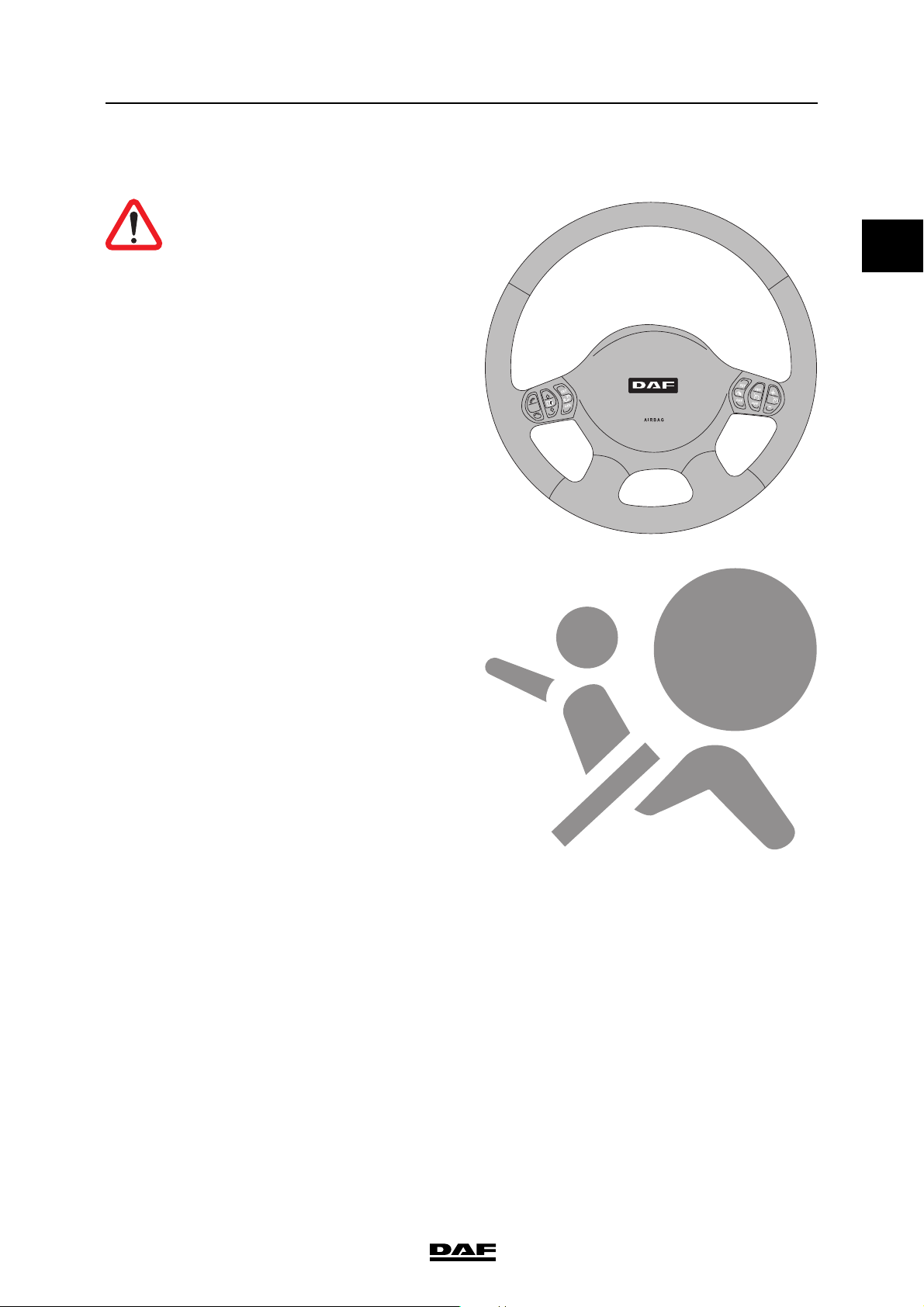
1.4 AIRBAG
WARNING! Airbag modules and
safety belt tensioners are
pyrotechnic systems and contain an
explosive charge.
Securing the vehicle
Vehicles equipped with an airbag and safety belt
tensioner system can be identified by a sticker
with the airbag symbol on the windscreen.
In addition, there is an identification 'AIRBAG'
visible on the steering wheel. A vehicle equipped
with an airbag also has an automatic safety belt
tensioner.
©
201426 1-5
Page 14
EMERGENCY RESPONSE GUIDE
1
G001312
1
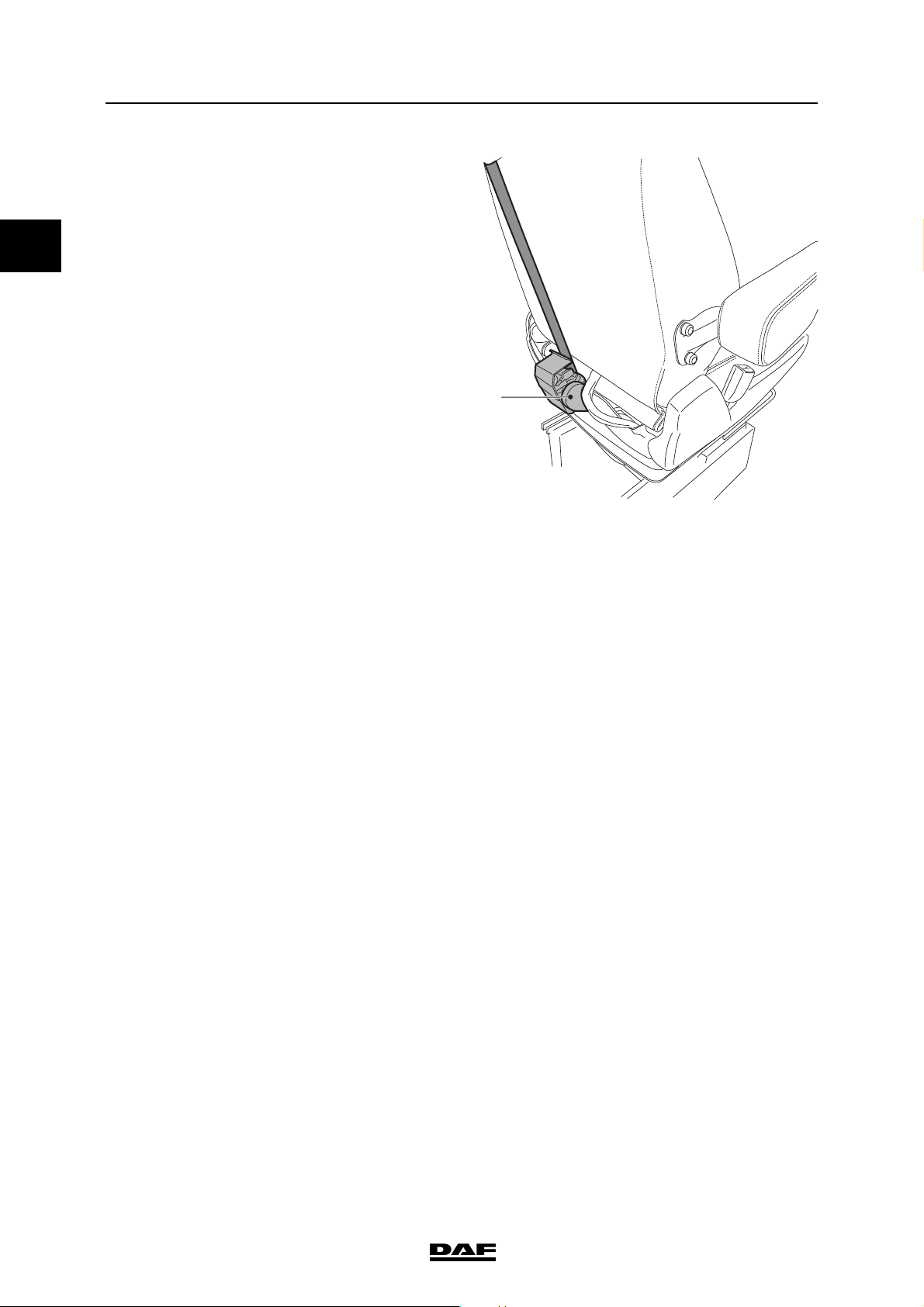
Securing the vehicle ΛΦ series
1 Safety belt tensioner
The automatic safety belt tensioner is fitted on the
rear side of the driver's and co-driver's seat.
Safety instructions
- Do not place any objects near undeployed
airbags
- Before any work is carried out on an airbag
system:
1. the ignition must be switched off.
2. the main switch must be turned off.
3. the battery clamp must be removed from
the negative pole.
4. wait at least 30 seconds.
- Never disconnect an electrical connector in
the airbag or safety belt tensioner circuits if
the electronic control unit is energised.
©
201426
1-6
Page 15

EMERGENCY RESPONSE GUIDE
1
i403576
ΛΦ series
1.5 FLUIDS
12 4
Securing the vehicle
3
6
5
1 Coolant: 48 litres
2 Engine oil: 17- 23.5 litres
3 Gearbox oil: 14 litres
4 AdBlue: 25 or 50 litres
5 Fuel: up to 430 litres
6 Battery acid
The capacities and position of the tanks depend
on the vehicle type.
AdBlue
AdBlue is a non-flammable, non-toxic, colourless,
odourless and water-soluble liquid.
AdBlue is a liquid consisting of 32.5% urea and
67.5% water.
AdBlue must meet the specifications according to
DIN 70070.
High temperatures
If AdBlue is heated in the tank to 50°C over a long
period of time, the decomposing AdBlue can
produce ammonia vapours. Ammonia vapours
have a pungent odour. For this reason, avoid
inhaling possible ammonia vapours escaping
when unscrewing the AdBlue filler cap. These
concentrations of ammonia vapours are neither
toxic nor hazardous to health.
K104001
Low temperatures
AdBlue freezes at temperatures of approximately
-11°C.
©
201426 1-7
Page 16

EMERGENCY RESPONSE GUIDE
1
Securing the vehicle ΛΦ series
WARNING!
AdBlue safety instructions
- Avoid direct contact.
- In the event of contact with the
skin, rinse with plenty of water.
- In the event of contact with the
eyes, rinse for at least 15
minutes with plenty of water and
seek medical assistance.
- If swallowed, rinse mouth with
plenty of water; do not induce
vomiting.
- Use in a ventilated area.
Procedure after spillage
- Rinse with plenty of water.
1-8
©
201426
Page 17

EMERGENCY RESPONSE GUIDE
1
G001936
G002346
ΛΦ series
1.6 REGENERATION UNIT
During regeneration the exhaust gases, the
surroundings of the regeneration unit and the
catwalk can reach high temperatures that can
potentially harm bystanders or the surrounding
area.
WARNING! There is a risk of fire or
other hazardous situation if the
temperature can ignite flammable
materials.
Switch off the regeneration unit
Set the switch in the OFF position to stop or
inhibit regeneration.
Securing the vehicle
©
201426 1-9
Page 18

EMERGENCY RESPONSE GUIDE
1
Securing the vehicle ΛΦ series
1-10
©
201426
Page 19

EMERGENCY RESPONSE GUIDE
1
ΛΦ series
2. STABILISING THE VEHICLE
2.1 SEAT ADJUSTMENT
NOTE: Before removing the seat, be
aware of the safety instructions if the
vehicle is equipped with an airbag and
therefore an automatic safety belt
tensioner.
NOTE: The seat can be adjusted if the
vehicle air pressure is at least 7 bar.
Seat settings
1 Seat length adjustment.
2 Seat cushion length adjustment.
3 Armrest (optional).
4 Backrest angle adjustment.
5 Seat cushion heating (only on driver seat
version).
6 Upper lumbar support adjustment (only
on comfort seat).
7 Lower lumbar support adjustment (only
on comfort seat).
8 Lateral support adjustment (only on
comfort seat).
9 Vertical seat damper.
10 Seat height adjustment.
11 Seat tilt adjustment
12 Quick down.
Stabilising the vehicle
3
4
5
2
10. Seat height adjustment
11. Seat tilt adjustment
12. Quick down
Knob down (seat in driving position): the seat drops to its lowest
position.
Knob up (with lowered seat): the
seat rises to the last height adjustment.
1
12 11 10 9 8 7 6
©
201426 2-1
Page 20

EMERGENCY RESPONSE GUIDE
1
M1 M2
STOP
C900268
Stabilising the vehicle ΛΦ series
2.2 AIR SUSPENSION CHASSIS
General
On vehicles equipped with air suspension, a
remote control unit is used to operate the vehicle
height.
The remote control unit is located against the
console of the driver's seat.
NOTE: This control unit can only be
operated when the ignition is switched
on.
NOTE: Unless stated otherwise, the
keys need only be pressed once briefly.
Remote control A
rear of truck selected
automatic setting of normal driving
height
lifting of chassis to pre-set height
as M1, but for a different chassis
height
lifting of selected chassis ends
when the key is released
lowering of selected chassis ends
when the key is released
all adjustments are stopped
2-2
©
201426
Page 21

EMERGENCY RESPONSE GUIDE
1
G001959
ΛΦ series
2.3 CABIN SUSPENSION
The cabin is equipped with mechanical
suspension.
Rear cabin mechanical suspension
Front cabin mechanical suspension
At the front the cabin can have rubber blocks or
springs. They can be reached by removing the
lower grille, and if necessary, the headlight
panels.
Stabilising the vehicle
©
201426 2-3
Page 22

EMERGENCY RESPONSE GUIDE
1
Stabilising the vehicle ΛΦ series
2-4
©
201426
Page 23

EMERGENCY RESPONSE GUIDE
1
ΛΦ series
3. RELEASING A TRAPPED DRIVER
3.1 CABIN TYPES
12
Releasing a trapped driver
3
1Day Cab
2 Extended Day Cab
3 Sleeper Cab
G002348
©
201426 3-1
Page 24

EMERGENCY RESPONSE GUIDE
1
1850
1603
580
2130
G002442
620
1610
1610
400
8-12t 14-16t
19t 8-12t
120
350
240
290
1610
345
240
340
Releasing a trapped driver ΛΦ series
3.2 CABIN DIMENSIONS
The external dimensions from the ground vary
depending on the tyre size, choice of suspension,
load and settings.
Day Cab
3-2
©
201426
Page 25

EMERGENCY RESPONSE GUIDE
1
1850
2003
620
1610
1250
1250
1250
400
120
1610
350
290
240
1610
2130
345
340
240
580
G002445
8-12t 14-16t
19t 14-16t
ΛΦ series
Extended Day Cab
Releasing a trapped driver
©
201426 3-3
Page 26

EMERGENCY RESPONSE GUIDE
1
1130
1610
1610
1850
2000
2003
620
600
700
1610
400
120
120
1130
120
1130
2130
120
350
290
240
345
340
240
580
G002446
8-12t 14-16t
19t 19t
Releasing a trapped driver ΛΦ series
Sleeper Cab
3-4
©
201426
Page 27

EMERGENCY RESPONSE GUIDE
1
G002349
ΛΦ series
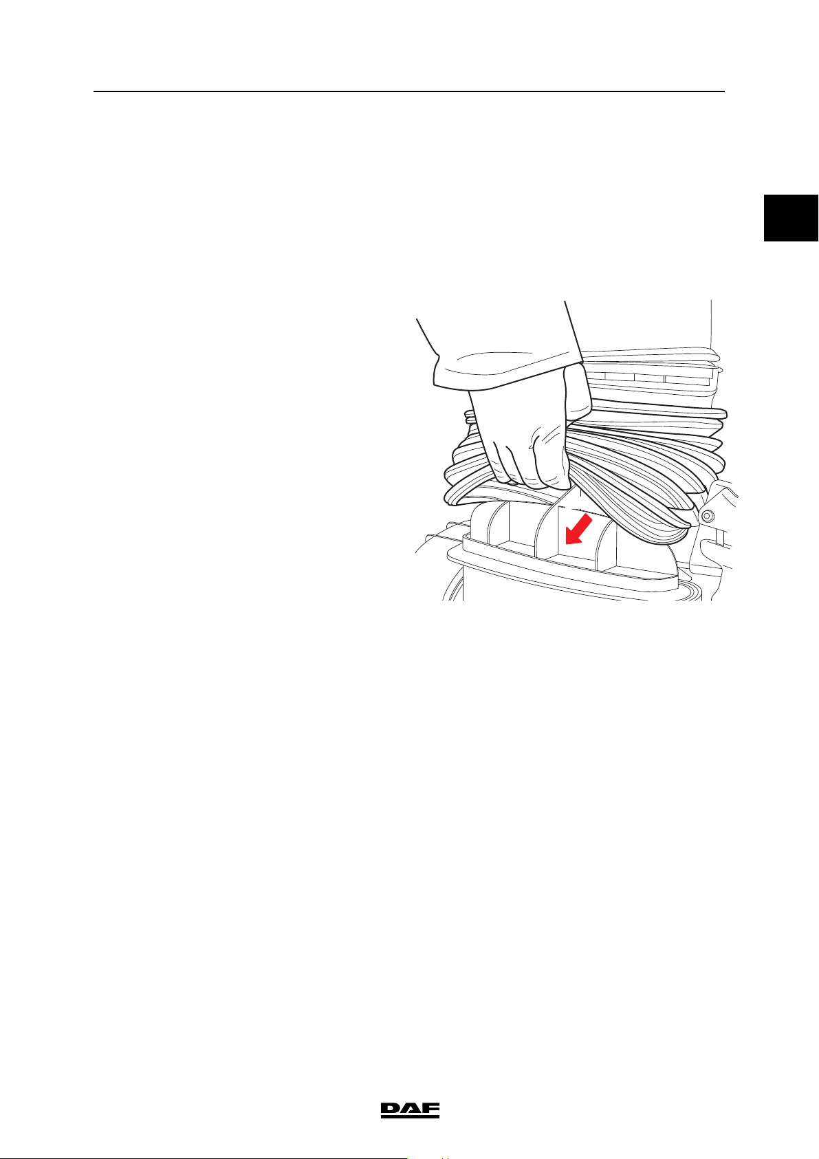
3.3 OPENING THE GRILLE
Open the front panel by gripping it at the bottom
and lifting it up. The front panel tilts upwards and
is held in position by two gas struts.
Releasing a trapped driver
©
201426 3-5
Page 28

EMERGENCY RESPONSE GUIDE
1
Releasing a trapped driver ΛΦ series
3.4 DOORS
1 Hinge
2 Wiring harness
3 Door check
1
2
1
3
G001310
3-6
©
201426
Page 29

EMERGENCY RESPONSE GUIDE
1
ΛΦ series
3.5 DOOR LOCK
The door lock is installed higher than the door
handle. The position is indicated in the image.
Releasing a trapped driver
G002350
©
201426 3-7
Page 30

EMERGENCY RESPONSE GUIDE
1
G002351
Releasing a trapped driver ΛΦ series
3.6 MECHANICAL STEERING WHEEL ADJUSTMENT
To adjust, pull the handle towards you and
simultaneously move the steering column to the
desired position. The steering column is locked
by releasing the handle.
3-8
©
201426
Page 31

EMERGENCY RESPONSE GUIDE
1
K101546
ΛΦ series
3.7 STEERING WHEEL ADJUSTMENT
NOTE: The steering wheel can be
adjusted if the vehicle air pressure
(circuit 4) is at least 7 bar.
Adjusting
Push up the two-position switch. The steering
column is temporarily unlocked. The height and
angle of the steering wheel can now be adjusted.
Releasing a trapped driver
G001293
Locking
Push down the two-position switch. The steering
column is locked.
NOTE: A slight hissing noise, caused
by the two-position switch, is audible
while the steering wheel is being
adjusted. If the steering column has not
been locked, this switch locks it
automatically after 20 - 30 seconds.
©
201426 3-9
Page 32

EMERGENCY RESPONSE GUIDE
1
Releasing a trapped driver ΛΦ series
3-10
©
201426
Page 33

EMERGENCY RESPONSE GUIDE
1
ΛΦ series
4. TOWING INFORMATION
4.1 REMOVING THE DRIVE SHAFT
- Make sure that the parking brake is
engaged.
- Loosen the bolts, do not remove them.
- Loosen the bearing.
- Hold the shaft while removing the bolts.
- Fix the bearings to the shaft.
- Fasten the shaft to the chassis.
- Cover the drive shaft joint with a plastic bag.
Towing information
©
201426 4-1
Page 34

EMERGENCY RESPONSE GUIDE
1
R601642
Towing information ΛΦ series
4.2 RELEASING THE PARKING BRAKE
WARNING!
- Never release the park brake on
an incline without precautionary
measures.
Releasing the park brake on an
incline causes the vehicle to move
unintentionally. This can lead to
serious injury and damage to the
vehicle.
1. Place wheel chocks in front of and behind the
wheels.
NOTE: It is not permitted to use a
socket wrench to loosen the
releasing bolt.
2. Turn the releasing bolt anti-clockwise as far
as the stop using a ring spanner.
3. Carry out this operation for each spring
brake cylinder.
NOTE: Place a no brakes warning
label on the steering wheel.
4. Bring the park brake back in operating order
by turning the releasing bolts clockwise as
far as possible and tightening them to a
torque of 45 Nm (75 Nm for the releasing bolt
with control pin). The pressure in the spring
brake cylinder circuit must be at least 6.5 bar.
4-2
©
201426
Page 35

EMERGENCY RESPONSE GUIDE
1
K103829
ΛΦ series
4.3 TOWING
It is possible to install a towing eye behind the
grille.
Always use a towing bar when towing. Deviation
from this rule is only allowed in emergencies.
When towing, the fault messages may appear in
the master display when the ignition is switched
on.
NOTE: The maximum permissible
vehicle speed, weight and distance
vary per country.
Tractors may be fitted with a small towing hook at
the rear end of the chassis. Use this towing hook
only for light shunting work.
Being towed by another vehicle
WARNING! Towing a fully loaded
vehicle or a vehicle with trailer
attached can result in unstable
vehicle behaviour during critical
driving situations applying to the
towing and/or towed vehicle. This
can lead to very dangerous
situations. High forces and tensions
in the chassis and drive line of the
vehicles can also lead to damage to
the vehicles.
- Do not tow the vehicle when
fully loaded or with a trailer
attached.
Towing information
WARNING! The towed vehicle can be
located asymmetrically (left or right)
behind the tractor. Towing at an
angle larger than 20° with the vehicle
centreline can result in unstable
vehicle behaviour for the towing
and/or towed vehicle during critical
driving situations. This can lead to
very dangerous situations. High
forces and tensions in the chassis
and drive line of the vehicles can
also lead to damage to the vehicles.
- Towing may not take place at an
angle larger than 20° with the
vehicle centreline.
©
201426 4-3
Page 36

EMERGENCY RESPONSE GUIDE
1
Towing information ΛΦ series
WARNING! When the engine is not
running during towing and no
additional measures are taken, there
is no power steering and no air is
supplied to the braking system. This
results in difficult steering and
increased brake pedal force and
ultimately leads to automatic
engagement of the parking brake.
This can lead to very dangerous
situations.
- Short distance towing: Release
the parking brake, see
'Releasing the parking brake'
and adapt the driving style of the
towing combination.
- Long distance towing: Use a
recovery vehicle.
- To clear the towing eyes, remove the black
grid from the lower grille by turning the
attachment screws a quarter turn.
- Always fix the tow rod with its original
attachment pin (part of the vehicle tool kit) in
the towing eyes.
- Turn the ignition key so that the steering
wheel is released (unless the vehicle is in a
hoist, see below).
- If there is insufficient pressure in the air
reservoirs, release the parking brake. See
section 'Releasing the parking brake'.
- To prevent damage to the gearbox, always
disconnect the propeller shaft from the
differential.
CAUTION: If the propeller shaft
remains connected during towing,
the gearbox may be seriously
damaged.
- Always disconnect the propeller
when the vehicle is being towed.
G002351
If the differential is damaged:
- Hoist the vehicle at the rear and lock the
steering wheel in the straight-ahead
position.
Long-distance towing
If the vehicle must be moved over a larger
distance, this must be done by a recovery vehicle
that lifts the vehicle to be towed under its front
axle. Do not run the engine because of the risk of
engine lubrication failure.
Tow starting
If the vehicle must be towed to start the engine,
the ignition key must first be turned clockwise to
position D, ignition on.
4-4
©
201426
Page 37

EMERGENCY RESPONSE GUIDE
1
ΛΦ series
Towing information
NOTE: Vehicles with an AS Tronic Lite
gearbox or automatic gearbox cannot
be towed to start the engine.
©
201426 4-5
Page 38

EMERGENCY RESPONSE GUIDE
1
Towing information ΛΦ series
4-6
©
201426
Page 39

EMERGENCY RESPONSE GUIDE
1
ΛΦ series
5. LIFTING INFORMATION
5.1 LIFTING AT THE FRONT OR BACK
The truck can be lifted under the axles, frame
structure or wheel stations.
Lifting information
©
201426 5-1
Page 40

EMERGENCY RESPONSE GUIDE
1
Lifting information ΛΦ series
5.2 JACKING UP MECHANICALLY SPRUNG FRONT AXLES
Place the jack under the special shock absorber
bracket.
CAUTION: Do not jack up under the
protection bar at the front of the
vehicle. This is a protection bar
made of sheet metal. If you jack up
the vehicle under the protection bar
it collapses.
5-2
©
201426
Page 41

EMERGENCY RESPONSE GUIDE
1
ΛΦ series
5.3 JACK UP AT THE BACK
Place the jack under the jacking point at the
bottom of the spring bracket.
Lifting information
©
201426 5-3
Page 42

EMERGENCY RESPONSE GUIDE
1
Lifting information ΛΦ series
5-4
©
201426
Page 43

Page 44

English
Printed in the Netherlands DW53293901
 Loading...