

Page 1

6
ΧΦ65/75/85 series
STRUCTURE
Structure
TECHNICAL DATA
DIAGNOSTICS
BRAKE DIAGRAMS FOR THE FULLY PNEUMATIC BRAKE SYSTEM
EBS BRAKE SYSTEM BRAKE DIAGRAMS
OPERATION OF BRAKE COMPONENTS
BRAKE SYSTEM AND COMPONENTS
BRAKING PERFORMANCE AND BRAKE EQUALISATION
0
1
2
3
4
5
6
©
200423 DW23241603
Page 2

Page 3

6
TECHNICAL DATA
ΧΦ65/75/85 series
0 Technical data
CONTENTS
Page Date
1. BRAKE SYSTEM AND COMPONENTS . . . . . . . . . . . . . . . . . . . . . . . . . . . . . . . 1-1 . . . . . 200423
1.1 General . . . . . . . . . . . . . . . . . . . . . . . . . . . . . . . . . . . . . . . . . . . . . . . . . . 1-1 . . . . . 200423
1.2 Tightening torques . . . . . . . . . . . . . . . . . . . . . . . . . . . . . . . . . . . . . . . . . . . 1-16 . . . . 200423
1.3 Lubricants . . . . . . . . . . . . . . . . . . . . . . . . . . . . . . . . . . . . . . . . . . . . . . . . 1-19 . . . . 200423
2. BRAKING PERFORMANCE AND BRAKE EQUALISATION . . . . . . . . . . . . . . 2-1 . . . . . 200423
2.1 General . . . . . . . . . . . . . . . . . . . . . . . . . . . . . . . . . . . . . . . . . . . . . . . . . . 2-1 . . . . . 200423
Contents
0
©
200423 1
Page 4

TECHNICAL DATA
6
0
Contents
ΧΦ65/75/85 series
2
©
200423
Page 5

6
TECHNICAL DATA
ΧΦ65/75/85 series
1. BRAKE SYSTEM AND COMPONENTS
1.1 GENERAL
Coding of components
All components have been provided with number
codes.
Structure of the code
First digit
Where one connection performs several
functions, additional 1
These are separated by a hyphen.
Often used:
1 energy supply (pressure)
2 energy discharge (outgoing command)
3 bleeding
4 control connection (incoming command)
Little used:
0 suction connection
5 vacant
6 vacant
7 anti-freeze connection
8 lubricating oil connection
9 coolant connection
st
digits will be allocated.
Brake system and components
0
Second digit
If there are several connections with the same
function, a 2
after the 1
Application example: empty/load relay valve
Meaning:
1 air compressor energy supply
2 energy discharge (command) to the next
component
41 control connection (incoming)
42 second control connection (incoming)
nd
digit will be added immediately
st
one.
©
200423 1-1
Page 6

TECHNICAL DATA
6
0
Brake system and components
Compressor
CF65 series
Type
Make: Knorr SWC 9057
Version: 1 cylinder, water cooled, 255 cc
CF75/85 series
Type
Make: Wabco 911 504 ...
Version: 2 cylinder, water cooled
Rejection sizes Wabco 911 504 ... compressor
Cylinder bore at the turning point of the
first piston ring 75.022 mm
Height of piston ring groove:
first groove: 2.035 mm
second groove: 2.035 mm
third groove: 4.047 mm
Gudgeon pin hole diameter: 15.018 mm
Gudgeon pin diameter: 14.992 mm
Piston diameter, measured along the length of
the piston pen on the underside of the piston skirt. 74.962 mm
Gudgeon pin bearing in connecting rod: 15.047 mm
Crankshaft bearing diameter, non-drive side: 35.070 mm
Crankshaft main bearing, non-drive side: 34.963 mm
Crankshaft diameter at the connecting rod: 32.963 mm
Always replace rolling bearing on drive side
ΧΦ65/75/85 series
1-2
©
200423
Page 7

6
2
3
4
5
6
7
TECHNICAL DATA
ΧΦ65/75/85 series
Brake system and components
Air supply unit
A
B
2123 3 23 25
D
F
1
NJK
C
1
E
0
21
24
26 22
G
6.1
12
3
6.2
Knorr ZB4545 - II38005F, ZB4578 - K000394, ZB4580 - K000396 versions
(used on front-axle leaf suspension)
R
A
21
23 3 23 25
Q
12
29 11
B
21
0
MH
6.
U
6.
P
L
P
P
U
R600702
6.
6.
6.
6.
H
D
F
21
NJ
K
M
L
P
P
U
P
U
C
1
E
0
24
26 22
G
6.1
12
3
6.2
R600703
Knorr ZB4548 - II38799F, ZB4579 - K000395 versions (used on front-axle leaf suspension)
A air dryer/pressure regulator (unit) K pressure limiting valve, circuit 3
B 4-circuit protection valve (unit) L pressure relief valve, circuit 3
C filter/drying grid M flow back valve, circuit 3
D pressure regulator N pressure relief valve with bypass, circuit 4
E blow-off valve P pressure sensors
F pneumatic time switch for regeneration Only for use on front-axle air suspension:
G heating element Q pressure relief valve
H pressure relief valve with bypass, circuit 1 R non-return valve
J pressure relief valve with bypass, circuit 2
6.2
6.3
6.4
6.5
6.6
6.7
©
200423 1-3
Page 8

TECHNICAL DATA
6
0
Brake system and components
supply pressure in circuit 1, connection 21 9.8 - 10.6 bar
supply pressure in circuit 2, connection 22 9.8 - 10.6 bar
supply pressure in circuit 3, connection 23 8.1 - 8.5 bar
supply pressure in circuit 3, connection 25 7.9 - 8.5 bar
supply pressure in circuit 4, connection 24 9.8 - 10.6 bar
supply pressure in circuit 4, connection 26 9.8 - 10.6 bar
opening pressure of circuits 1, 2 and 4 6.5 - 7.0 bar
opening pressure of circuit 3 7.0 - 7.5 bar
Static closing pressure, all circuits 4.5 bar
circuit 1 activation pressure for flow-back function
of circuit 3 4.5 bar
cut-out pressure of pressure regulator 9.8 - 10.6 bar
cut-in pressure of pressure regulator 1.0 - 1.8 bar below the cut-out pressure
safety valve opening pressure 12.8 - 13.2 bar
cut-in temperature of heating element 7C
cut-out temperature of heating element 29C
re-set time approx. 20 sec.
ΧΦ65/75/85 series
pressure sensor reading, circuits 1 and 2
(connections 6.2 - 6.7 in the diagrams above)
Pressure relief valve
overflow pressure 10.0 bar
Ua(V)
5V
4V
3V
2V
1V
0V
120246810
P
21.22
(bar)
R600701
1-4
©
200423
Page 9

6
TECHNICAL DATA
ΧΦ65/75/85 series
Foot brake valve
Type
Make: Knorr DX 61A
Pressure difference between
circuits 1 and 2 0.25 bar
Actuating pressure difference
between circuits 1 and 2 0.2 bar
11
10
9
p21/22 [bar]
8
7
6
5
4
3
2
Inshot 0.2–0.1
1
0
12
20
60
100
140
180
Brake system and components
P22 (P11=0)
21
22
3 4 5 6 7 8 9 10 11 12 13 14
0
Stroke (mm)
220
260
N
Connection 11 circuit 1 supply
Connection 12 circuit 2 supply
Connection 21 circuit 1 braking pressure
Connection 22 circuit 2 braking pressure
Load sensing valve, leaf suspension
Characteristic
380–20N
R600542
R600704
©
200423 1-5
Page 10

TECHNICAL DATA
6
0
Brake system and components
Load sensing valve, air suspension
Characteristic
Brake light switch
Type
Make: Messmer 131 733
Cut-in pressure, brake light switch (make contact) 0.4 - 0.6 bar
0.6
10
9
p2 [bar]
8
7
6
5
4
3
2
1
–0.2
1:1
10
ΧΦ65/75/85 series
p41
p42
p41
p42
p41
p42
2345678910
p4 [bar]
= 4.65 bar
= 3 bar
= 0.3 bar
R600705
Note:
If the vehicle has EBS, the brake light switch is
located in the foot brake valve.
Low pressure switch
Brake drum design
Make: Wabco 441 014 ...
Cut-out pressure (break contact) 4.7 - 5.7 bar
Disc brake design
Make: Wabco 441 014 ...
Cut-out pressure (break contact) 6.1 - 7.1 bar
1-6
©
200423
Page 11

6
TECHNICAL DATA
ΧΦ65/75/85 series
Empty/load relay valve
Type
Make: Wabco 973 011 106
Maximum reduction ratio 1 : 1.5
Actuating pressure 0.25 bar
Fitted with internal filter and silencer
Application: FAT vehicle
10
9
P2(bar)
8
7
6
5
4
3
2
1
0
Brake system and components
P
= P
42
41
1:1.5
P
= 0
42
2345678910
1
+
0,1
0,25
0
P41(bar)
Type
Make: Wabco 973 011 107
Maximum reduction ratio 1 : 2.7
Actuating pressure 0.25 bar
Fitted with internal filter and silencer
Application: FAD vehicle
FAC vehicle
FAX vehicle
FAL vehicle
10
9
P2(bar)
8
7
6
5
4
3
2
1
0
P
= P
42
41
1:2.7
P
= 0
42
1
2345678910
+
0,1
0,25
R600328
P41(bar)
R600330
©
200423 1-7
Page 12

TECHNICAL DATA
6
0
Brake system and components
Relay valve
Version for parking brake
Make: Knorr AC 577A
Fitted with silencer
Relay valve
Version for service brake
Make: Wabco 973 011 009
Fitted with internal filter and silencer
8,9
10
-0,2
9
0
8
ΧΦ65/75/85 series
9
8
P2 (bar)
7
6
5
4
3
2
1
10 23456789
P4 (bar)
R 600363
7
6
P2 (bar)
5
4
3
2
1
10 2345678910
0,5
–0,1
P4 (bar)
R 600602
1-8
©
200423
Page 13

6
TECHNICAL DATA
ΧΦ65/75/85 series
Relay valve
Version for service brake
Make: Wabco 973 011 008
Fitted with internal filter and silencer
ABS valve
Resistance of magnet coil (at approx. 25C) 10 - 20 ohm
10
0
9,2
-0,2
9
8
7
6
5
4
3
2
1
0
MAX. 0,2
Brake system and components
0
12345678910
R600640
Electrical connections
1. magnet coil bleed point
2. mass
3. magnet coil air admission point
1
2
3
21
3
123
R600370
©
200423 1-9
Page 14

TECHNICAL DATA
6
0
Brake system and components
ASR solenoid valve
1. Supply
2. Port, two-way valve
3. Bleed
Trailer control valve
Type
Make: Knorr AC 599A
Explanation of graph
B Curve of intact circuit 1, circuit 2, or failure in
circuit 1 or circuit 2
C Setting range, braking pressure advance
Advance
Input pressure 3 bar
Output pressure 3 bar
(corresponds to 0.6 bar
advance = factory setting)
Advance adjustment
2,2
P22(bar)
+
0,2
0
ΧΦ65/75/85 series
1
2
3
R600484
9
8
7
6
5
4
3
2
1
P11/12 = 8bar
P43 = 8bar
C
B
C
Adjusting screw (Allen type, 6 mm)
Clockwise increases the advance
Anti-clockwise decreases the advance
Explanation of graph
Output pressure on connection 22 (P22).
Graph is applicable if the parking brake is
applied.
P22(bar)
7,3
1
0
<
0,35
9
8
7
6
5
4
3
2
1
0
23456
P11/12 = 8bar
1
23456
78910
8,6
P41/42(bar)
R600333
789
6,3
P43(bar)
1-10
R600332
©
200423
Page 15

6
TECHNICAL DATA
ΧΦ65/75/85 series
Safety valve
Type
Make: Voss 0 268 874 200
Opening pressure reading approx. 16 bar
Parking brake valve with drawn vehicle
connection
Type
Make: Knorr DPM90DA (with test position)
Knorr DPM93D (without test position)
Knorr DPM90AA (without test
position with electrical switch)
(special application)
Max. output pressure
in driving position
(with test position) approx. 8.5 bar
Brake system and components
0
Max. output pressure
in driving position
(with test position) approx. 8.5 bar
R600706
©
200423 1-11
Page 16

TECHNICAL DATA
6
0
Brake system and components
Parking brake without drawn vehicle
connection
Type
Make: Knorr DPM92D
Max. output pressure
in driving position approx. 8.5 bar
ΧΦ65/75/85 series
Brake lining
Drum brakes
TYPE NOTES
DAF 2100 Installed on LHD vehicles
DAF 3100 Installed on RHD vehicles
Beral 1561 09N044 leading rear axle (used on FTP vehicle)
The bearing pattern of the brake lining can be
improved by grinding down the brake lining to
a diameter which is max. 1 mm smaller than
the drum diameter.
The space between brake shoe and lining must
not be more than 0.1 mm.
Minimum brake lining thickness
height of wear indicator or 1 mm above rivet head
M6002
1-12
©
200423
Page 17

6
TECHNICAL DATA
ΧΦ65/75/85 series
09N044 leading rear axle (used on FTP
vehicle)
Minimum lining thickness 5 mm
Disc brakes, SB7000 and SN7000 series
TYPE NOTES
DAF 1200 Fitted to all vehicles
Brake drum
General
A brake drum may be used until the inside
diameter has reached the maximum permissible
value, as specified in the table below.
As soon as this diameter is exceeded, the brake
drum must be replaced.
Brake diameter Standard brake-drum
diameter in mm
Ovality
314 + 0,127 317,3 316,3
12
3
/8"
Maximum in mm Maximum
Brake system and components
0
reconditioning
dimension in mm
13" 330,2 + 0,127 333,2 332,3
1
15
/2" 393,7 + 0,127 396,7 395,7
16" 406,6 + 0,250 409,6 408,6
1
16
/2" 420 + 0,250 425 423
310 mm 310 + 0,210 313 312
325 mm 325 + 0,230 328 327
360 mm 360 + 0,230 363 362
375 mm 375 + 0,230 378 377
420 mm 420 + 0,250 425 423
09N044 leading rear axle (used on FTP
vehicle)
Brake diameter Standard brake-drum
diameter in mm
300 mm 300 298 - 299 mm
The ovality (deformation) of the brake drum is
checked with the drum in position on the hub,
or on a brake dynamometer.
Maximum in mm Maximum
reconditioning
dimension in mm
Brake drums with cracks exceeding a width of
0.7 mm or a length of 50 mm may not be reused.
©
200423 1-13
Page 18
TECHNICAL DATA
6
0
Brake system and components
Automatic slack adjuster for drum brakes
Automatic slack adjuster travel (Haldex) 35 - 40 mm
Reverse torque value of adjusting bolt > 18 Nm
Axial play on the brake camshaft 0.5 - 1.0 mm
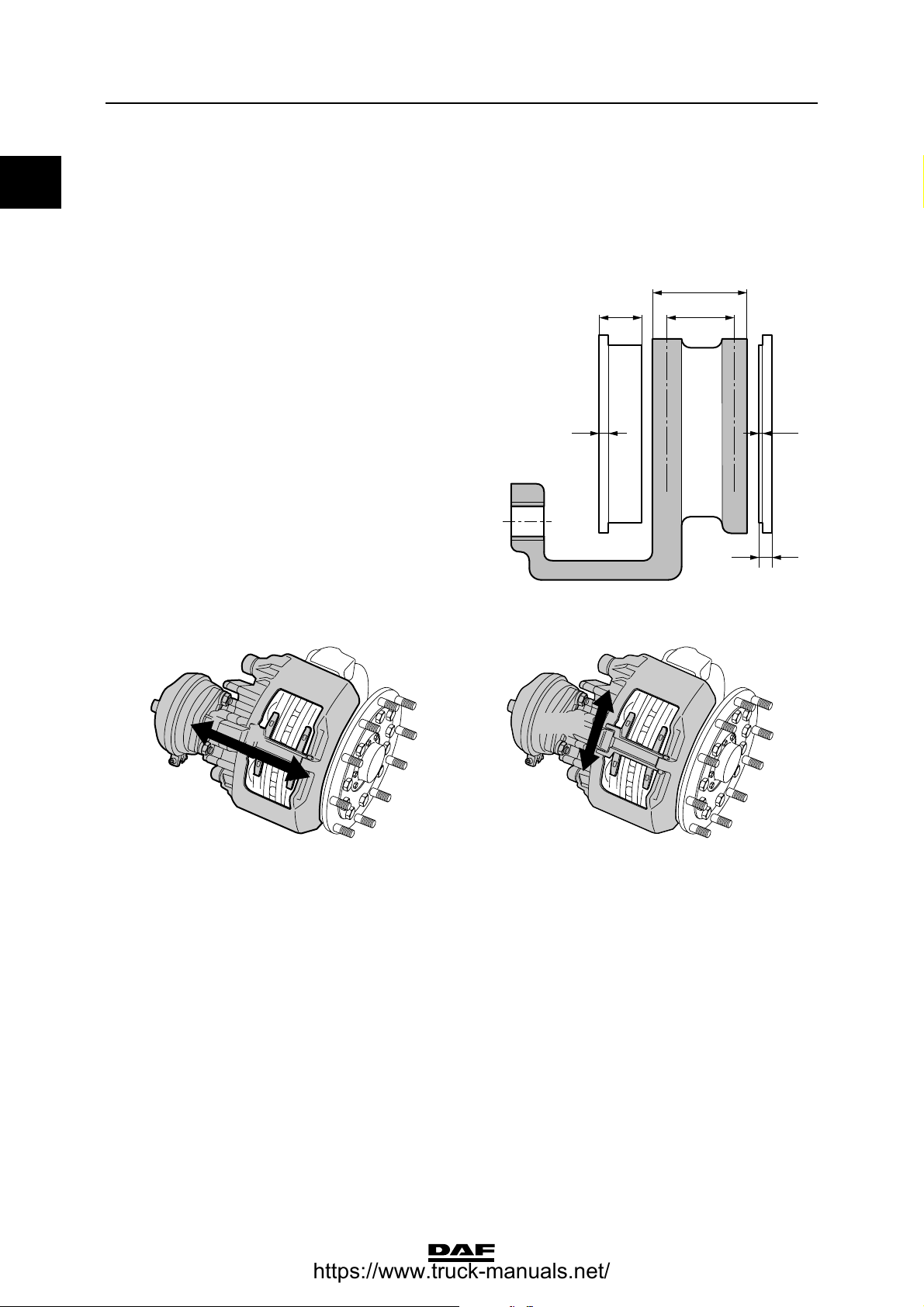
Brake pad
maximum brake pad
thickness (C) 30 mm
0 minimum lining thickness (E) 2 mm
minimum brake pad thickness (F),
with 9 mm rear plate thickness (D) 11 mm
replacing:
all brake pads at the same time for each axle,
and with the specified lining only.
Brake pad/brake disc play 0.6 - 1.0 mm
ΧΦ65/75/85 series
A
C
B
ED
F
Brake caliper
A
R600708
Brake caliper play in axial direction (direction A) 0.6 - 1.0 mm
Brake caliper play on the guide sleeves ("Y" - "X") Maximum 2.0 mm
Y - X
R600489
R600712
1-14
©
200423
Page 19

6
TECHNICAL DATA
ΧΦ65/75/85 series
Brake disc
maximum brake disc
thickness (A) 0 45 mm
minimum brake disc thickness (B)
(rejection dimension, disc needs
to be replaced) 37 mm
minimum thickness, turning
dimension 40 mm
Note:
If it is established during brake pad replacement
that the brake thickness is less than or equal to
39 mm, the brake disc must also be replaced.
The following signs of wear are permissible:
A1 crazy cracking.
B1 cracks running to the centre up to 1.5 mm
wide and deep, max. 0.75 x friction surface
width (a).
C1 unevenness in the disc surface up to
1.5 mm.
Brake system and components
A
B
1
a
A
C
B
ED
F
R600489
1
0
max. 0,75 x a
max. 1,5 mm
Not permissible:
D1 through-going cracks.
D
C
1
1
R600471
©
200423 1-15
Page 20

TECHNICAL DATA
6
0
Brake system and components
1.2 TIGHTENING TORQUES
Note:
The tightening torques stated in this section are
different from the standard tightening torques
stated in the overview of the standard tightening
torques.
The other threaded connections not specified
must therefore be tightened to the torque stated
in the overview of standard tightening torques.
When attachment bolts and nuts are replaced,
it is important that - unless stated otherwise these bolts and nuts are of exactly the same
length and property class as those removed.
SAFETY VALVE
Attachment 72 Nm
BRAKE CALLIPER - BRAKE CARRIER
Sliding sleeve Allen screws (SB7000) 285 Nm
Sliding sleeve Allen screws (SN7000) 180 Nm + 90
Brake caliper attachment bolts 440 Nm
Pressure tool, guide bush bellows 8 Nm
Rubber bearing bush pressure tool (only SN7000) 8 - 45 Nm
(1)
(2)
ΧΦ65/75/85 series
(1)
(1) Always use new bolts, provided with locking compound.
New bolts are supplied with locking compound already
applied.
(2) In the case of versions with Knorr disc brakes,
the attachment of the brake caliper against the stub axle
changed starting from production week 2002-25.
Five bolts are now used instead of six bolts. There is still
a hole for the 6
no hole on the stub axle.
BRAKE DISC
Locking plate attachment bolts 30 Nm
th
bolt (5) on the brake carrier, but there is
6 23 1 54
R600520
1-16
©
200423
Page 21

6
TECHNICAL DATA
ΧΦ65/75/85 series
BRAKE CYLINDER
Attachment nuts 195 Nm
Release bolt 45 Nm
Release bolt (version with indication pin) 75 Nm
SPRING BRAKE CYLINDER
Fixing nuts of spring brake cylinder 180 - 210 Nm
Fixing bolts of the brake chamber clamping strap 34 Nm
Release bolt (at least 5.1 bar) 25 Nm
VOSS COUPLING 232
Socket 12 Nm
BLOW-OFF VALVE
Attachment 25 Nm
Air compressor
There are two types of compressors: one version
used in production until 2002-47 and one version
used in production from 2002-48.
Compressors can be identified as follows:
Brake system and components
0
112
R600743
< 2002-48 2002-48
The cylinder head of compressors used up to
2002-48 consists of three aluminium parts (1).
The cylinder head of compressors used from
2002-48 consists of two aluminium parts (1)
and a steel plate (2).
Air compressor tightening torques greater
than or equal to 2002-48
Delivery valve attachment nuts 5 Nm + 90 angular displacement
Connecting rod bolts 6 Nm + 70 angular displacement
©
200423 1-17
Page 22

TECHNICAL DATA
6
0
Brake system and components
5
1
3
7
8
2
4
6
R600742
Cylinder head bolts
Phase 1, bolts 7 - 8 (in sequence) 6 Nm
Phase 2, bolts 7 - 8 (in sequence) 90 angular displacement
Phase 3, bolts 1 - 2 - 6 - 5 - 4 - 3 (in sequence) 30 Nm
Phase 4, bolts 1 - 2 - 6 - 5 - 4 - 3 (in sequence) 90 angular displacement
Phase 5, bolts 7 - 8 (in sequence) 10 Nm
Phase 6, bolts 7 - 8 (in sequence) 90 angular displacement
ΧΦ65/75/85 series
Air compressor tightening torques greater
than or equal to 2002-48
Delivery valve attachment nuts 5 Nm + 90 angular displacement
Connecting rod bolts 6 Nm + 70 angular displacement
5
1
3
7
8
2
4
6
R600742
Cylinder head bolts
Phase 1, bolts 1 - 2 - 3 - 4 - 5 - 6 (in sequence) 30 Nm
Phase 2, bolts 1 - 2 - 3 - 4 - 5 - 6 (in sequence) 90 angular displacement
Phase 3, bolts 7 - 8 (in sequence) 7 Nm
Phase 4, bolts 7 - 8 (in sequence) 90 angular displacement
1-18
©
200423
Page 23

6
TECHNICAL DATA
ΧΦ65/75/85 series
1.3 LUBRICANTS
Brake calliper
Knorr SB7000
3
18
Brake system and components
0
20
21
19
17
1
22
6a
4
6
7
5
8
11
10
2
9
Renolit HLT2 (white) for parts 6, 7, 8,
the adjusters (not shown), the brake cylinder
lever and the flange surface for attachment of the
brake cylinder (DAF no. 1448907)
Sytheso GL EP1 (green), for parts 3, 5 (DAF no. 1448908)
16
15
14
R600746
©
200423 1-19
Page 24

TECHNICAL DATA
6
0
Brake system and components
Knorr SN7000
5
6a
6
3
ΧΦ65/75/85 series
20
21
18
19
17
1
22
7
4
8
15
11
10
2
Renolit HLT2 (white) for parts 3, 6, 7, 8,
the adjusters (not shown), the brake cylinder
lever and the flange surface for attachment
of the brake cylinder (DAF no. 1448907)
14
16
23
R600755
1-20
©
200423
Page 25

6
TECHNICAL DATA
ΧΦ65/75/85 series
Braking performance and brake equalisation
2. BRAKING PERFORMANCE AND BRAKE EQUALISATION
2.1 GENERAL
EBS tyre class
The tyre sizes are classified into tyre classes.
This tyre class information is necessary
to be able to assess the brake presentation,
by measurements of brake force.
This tyre class information is also necessary
for the EBS system to be able to evaluate
whether the electric EBS unit is programmed
when the tyre size is changed..
Tyre size change in EBS system
If the tyre size is changed in an EBS system and
the tyre size of the front and rear axle no longer
fall in the same tyre class, the changed tyre sizes
must be programmed into the electronic EBS
unit.
Tyre class Tyre size
0
Class 0 215/75 R 17.5
235/75 R 17.5
Class 1 295/60 R 22.5
255/70 R 22.5
315/60 R 22.5
275/70 R 22.5
Class 2 305/70 R 22.5
315/70 R 22.5
385/55 R 22.5
295/80 R 22.5
11 R 22.5
Class 3 385/65 R 22.5
315/80 R 22.5
11.00 R 20
12 R 22.5
12.00 R 20
13 R 22.5
©
200423 2-1
Page 26

TECHNICAL DATA
6
0
Braking performance and brake equalisation
Tyre size change in EBS 2 system
If the tyre size is changed in an EBS 2 system and
the tyre size of the front and rear axle no longer
fall in the same tyre class, it is not necessary to
program the electronic ESB 2 unit because the
electronic ESB 2 unit will automatically recognise
this change in tyre size.
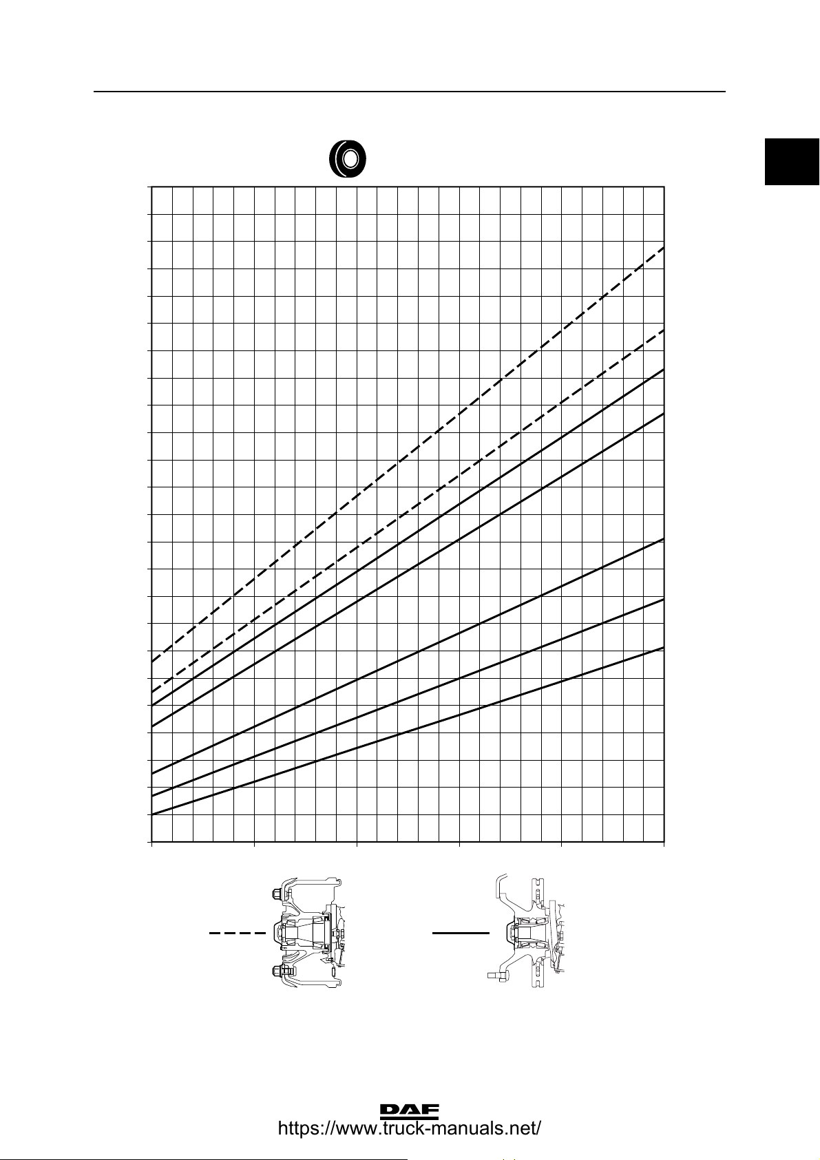
OVERVIEW OF BRAKING FORCES OF
EBS SYSTEM
This overview lists the braking forces graphs
based on tyre size. These braking force graphs
apply to the prime mover with EBS; these braking
force graphs can be used to check the braking
performance of an EBS prime mover.
Graph explanation
1 Brake force per wheel (N)
2 Tyre size
3 Type of brake cylinder + brake lever length
(if applicable)
4 Brake drum design
5 Disc brake construction
6 Pressure in brake cylinder (P)
7 Reference line of measured braking force
per wheel; the example shows a brake drum
construction and a 27" brake cylinder with
a brake lever length of 165 mm.
8 Reference line of the measured braking force
per wheel; the example shows a disk brake
construction and a 24" brake cylinder.
ΧΦ65/75/85 series
1
F (N)
27000
26000
25000
24000
23000
22000
21000
20000
19000
18000
17000
16000
15000
14000
13000
12000
11000
10000
9000
8000
7000
6000
5000
4000
3000
2 2,5 3 3,5 4 4,5
2
295/60R22,5
7
8
54
P (bar)
6
3
27"-165
24"
2-2
R600879
©
200423
Page 27

6
TECHNICAL DATA
ΧΦ65/75/85 series
Braking force graphs
F (N)
6000
5500
5000
4500
Braking performance and brake equalisation
235/75R17,5
0
9"-125
4000
3500
3000
2500
2000
2 2,5 3 3,5 4 4,5
P (bar)
R600865
©
200423 2-3
Page 28

TECHNICAL DATA
6
0
Braking performance and brake equalisation
F (N)
27000
26000
25000
24000
23000
22000
21000
20000
19000
18000
17000
16000
15000
295/60R22,5
ΧΦ65/75/85 series
27"-165
24"-165
24"
22"
16"
14000
13000
12000
11000
10000
9000
8000
7000
6000
5000
4000
3000
2 2,5 3 3,5 4 4,5
14"
12"
P (bar)
2-4
R600866
©
200423
Page 29

6
TECHNICAL DATA
ΧΦ65/75/85 series
F (N)
27000
26000
25000
24000
23000
22000
21000
20000
19000
18000
17000
16000
15000
Braking performance and brake equalisation
255/70R22,5
0
27"-165
24"-165
24"
22"
16"
14000
13000
12000
11000
10000
9000
8000
7000
6000
5000
4000
3000
2 2,5 3 3,5 4 4,5
14"
12"
P (bar)
R600867
©
200423 2-5
Page 30

TECHNICAL DATA
6
0
Braking performance and brake equalisation
F (N)
27000
26000
25000
24000
23000
22000
21000
20000
19000
18000
17000
16000
315/60R22,5
ΧΦ65/75/85 series
27"-165
24"-165
24"
22"
15000
14000
13000
12000
11000
10000
9000
8000
7000
6000
5000
4000
3000
2 2,5 3 3,5 4 4,5
16"
14"
12"
P (bar)
2-6
R600868
©
200423
Page 31

6
TECHNICAL DATA
ΧΦ65/75/85 series
F (N)
27000
26000
25000
24000
23000
22000
21000
20000
19000
18000
17000
16000
Braking performance and brake equalisation
275/70R22,5
0
27"-165
24"-165
24"
22"
15000
14000
13000
12000
11000
10000
9000
8000
7000
6000
5000
4000
3000
2 2,5 3 3,5 4 4,5
16"
14"
12"
P (bar)
R600869
©
200423 2-7
Page 32

TECHNICAL DATA
6
0
Braking performance and brake equalisation
F (N)
27000
26000
25000
24000
23000
22000
21000
20000
19000
18000
17000
16000
385/55R22,5
ΧΦ65/75/85 series
27"-165
24"-165
24"
22"
15000
14000
13000
12000
11000
10000
9000
8000
7000
6000
5000
4000
3000
2 2,5 3 3,5 4 4,5
16"
14"
12"
P (bar)
2-8
R600870
©
200423
Page 33
6
TECHNICAL DATA
ΧΦ65/75/85 series
F (N)
27000
26000
25000
24000
23000
22000
21000
20000
19000
18000
17000
16000
Braking performance and brake equalisation
305/70R22,5
0
27"-165
24"-165
24"
22"
15000
14000
13000
12000
11000
10000
9000
8000
7000
6000
5000
4000
3000
2 2,5 3 3,5 4 4,5
16"
14"
12"
P (bar)
R600871
©
200423 2-9
Page 34

TECHNICAL DATA
6
0
Braking performance and brake equalisation
F (N)
27000
26000
25000
24000
23000
22000
21000
20000
19000
18000
17000
16000
315/70R22,5
ΧΦ65/75/85 series
27"-165
24"-165
24"
22"
15000
14000
13000
12000
11000
10000
9000
8000
7000
6000
5000
4000
3000
2 2,5 3 3,5 4 4,5
16"
14"
12"
P (bar)
2-10
R600872
©
200423
Page 35

6
TECHNICAL DATA
ΧΦ65/75/85 series
F (N)
27000
26000
25000
24000
23000
22000
21000
20000
19000
18000
17000
16000
Braking performance and brake equalisation
295/80R22,5
0
27"-165
24"-165
24"
22"
15000
14000
13000
12000
11000
10000
9000
8000
7000
6000
5000
4000
3000
2 2,5 3 3,5 4 4,5
16"
14"
12"
P (bar)
R600873
©
200423 2-11
Page 36

TECHNICAL DATA
6
0
Braking performance and brake equalisation
F (N)
27000
26000
25000
24000
23000
22000
21000
20000
19000
18000
17000
16000
11R22,5
ΧΦ65/75/85 series
27"-165
24"-165
24"
22"
15000
14000
13000
12000
11000
10000
9000
8000
7000
6000
5000
4000
3000
2 2,5 3 3,5 4 4,5
16"
14"
12"
P (bar)
2-12
R600874
©
200423
Page 37

6
TECHNICAL DATA
ΧΦ65/75/85 series
F (N)
27000
26000
25000
24000
23000
22000
21000
20000
19000
18000
17000
16000
Braking performance and brake equalisation
385/65R22,5
0
27"-165
24"-165
24"
22"
15000
14000
13000
12000
11000
10000
9000
8000
7000
6000
5000
4000
3000
2 2,5 3 3,5 4 4,5
16"
14"
12"
P (bar)
R600875
©
200423 2-13
Page 38

TECHNICAL DATA
6
0
Braking performance and brake equalisation
F (N)
27000
26000
25000
24000
23000
22000
21000
20000
19000
18000
17000
16000
315/80R22,5
ΧΦ65/75/85 series
27"-165
24"-165
24"
22"
15000
14000
13000
12000
11000
10000
9000
8000
7000
6000
5000
4000
3000
2 2,5 3 3,5 4 4,5
16"
14"
12"
P (bar)
2-14
R600876
©
200423
Page 39

6
TECHNICAL DATA
ΧΦ65/75/85 series
F (N)
27000
26000
25000
24000
23000
22000
21000
20000
19000
18000
17000
16000
Braking performance and brake equalisation
12R22,5
0
27"-165
24"-165
24"
22"
15000
14000
13000
12000
11000
10000
9000
8000
7000
6000
5000
4000
3000
2 2,5 3 3,5 4 4,5
16"
14"
12"
P (bar)
R600877
©
200423 2-15
Page 40

TECHNICAL DATA
6
0
Braking performance and brake equalisation
F (N)
27000
26000
25000
24000
23000
22000
21000
20000
19000
18000
17000
16000
13R22,5
ΧΦ65/75/85 series
27"-165
24"-165
24"
22"
15000
14000
13000
12000
11000
10000
9000
8000
7000
6000
5000
4000
3000
2 2,5 3 3,5 4 4,5
16"
14"
12"
P (bar)
2-16
R600878
©
200423
Page 41

6
CF65/75/85 series Contents
DIAGNOSTICS
CONTENTS
Page Date
1. DISC BRAKE CONSTRUCTION 1-1 200324......................................... ....
1.1 Fault-finding table 1-1 200324................................................. ....
2. DRUM BRAKE CONSTRUCTION 2-1 200324........................................ ....
2.1 Fault-finding table 2-1 200324................................................. ....
1
ᓻ 200324
1
Page 42

1
6DIAGNOSTICS
Contents CF65/75/85 series
2
ᓻ 200324
Page 43

6
DIAGNOSTICS
CF65/75/85 series Disc brake construction
1. DISC BRAKE CONSTRUCTION
1.1 FAULT-FINDING TABLE
SYMPTOM: SQUEALING/NOISE DURING BRAKING
Possible cause Remedy
Worn brake pads Check brake pads and brake disc thickness
Loose parts Check disc brake construction
Wear/damage to hub bearing Check hub bearing play
Wear to internal parts of disc brake
construction
Incorrect vehicle combination Check vehicle combination
Incorrect front axle/rear axle brake pressure
setting
SYMPTOM: IRREGULAR BRAKE PAD WEAR
Possible cause Remedy
Fouled/corroded guide sleeves Check the guide sleeves
Dirt accumulation between moving parts of the
disc brake construction
Moisture and dirt on internal mechanical parts Check and clean the brake calliper seals
Brake pad stuck in the brake calliper. Incorrect
play between brake pads and brake carrier
Check internal parts
Check front axle/rear axle setting
Clean the disc brake construction
Check the play between brake pads and brake
carrier
1
ᓻ 200324
1-1
Page 44

1
6DIAGNOSTICS
Disc brake construction CF65/75/85 series
SYMPTOM: VEHICLE PULLS TO ONE SIDE DURING BRAKING
Possible cause Remedy
Differenceintyrepressure Check/correct tyre pressure
Differenceintyresize Check tyres
Different brake cylinder diameters Check brake cylinder diameters
Broken springs in brake cylinders Check brake cylinders
Leaking brake cylinders Check brake cylinders
Fouled brake cylinders Check brake cylinders for fouling
Excessive stub axle bearing play Check stub axle bearing play
Excessive steering ball joint play Check steering ball joint play
Excessive shackle pin play Check shackle pin play
Incorrect vehicle combination Check vehicle combination
Incorrect ABS operation Check ABS operation
Brake pad stuck in the brake calliper. Incorrect
play between brake pads and brake carrier
SYMPTOM: POOR BRAKING DECELERATION
Possible cause Remedy
Overload due to excessive loading Check vehicle loading condition
System pressure too low Check pressure regulator setting
Air leakage in the brake system Check the brake system for leakage
Insufficient braking power/poor condition of
trailer vehicle brake system
Pinched brake lines Check/replace brake lines
Brake cylinder stroke too large Check automatic brake adjuster
Frozen brake system Check brake system
Brake components affected by road salt Check brake components for fouling
Fouled brake cylinders Check brake cylinders for fouling
Incorrect brake cylinder diameter Check brake cylinders
Incorrect operation/setting of load sensing valve Check operation/setting of load sensing valve
Incorrect vehicle combination Check vehicle combination
Check the play between brake pads and brake
carrier
Check trailer vehicle
Incorrect ABS operation Check ABS operation
Brake pad stuck in the brake calliper. Incorrect
play between brake pads and brake carrier
Check the play between brake pads and brake
carrier
1-2
ᓻ 200324
Page 45

6
DIAGNOSTICS
CF65/75/85 series Disc brake construction
SYMPTOM: VIBRATIONS DURING BRAKING
Possible cause Remedy
Incorrect wheel tightening procedure Tighten wheels according to tightening
procedure
Non-standard wheels fitted Fit only standard wheels
Overload due to excessive loading Check vehicle loading condition
Incorrect front axle/rear axle brake pressure
setting
Wrong brake pad quality Check brake pads
Dirt/deposits on brake disc Check/clean brake disc
Loose parts Check disc brake construction
Wear/damage to hub bearing Check hub bearing play
Damage to disc brake Check thickness and condition of brake disc
Play in cab suspension Check cab suspension
Incorrect vehicle combination Check vehicle combination
SYMPTOM: LOCKING OF THE BRAKES
Possible cause Remedy
Incorrect setting of load sensing valve Check setting of load sensing valve
Thermal overload of non-locking axle brake
pads
Incorrect system pressure due to incorrect
pressure regulator setting
Check front axle/rear axle setting
Check non-locking axle brake pads
Check pressure regulator setting
1
Defective trailer vehicle brake system Check trailer vehicle brake system
Incorrect vehicle combination Check vehicle combination
Incorrect ABS operation Check ABS operation
Tyres have too little profile Check profile
Brake pad stuck in the brake calliper. Incorrect
play between brake pads and brake carrier
Check the play between brake pads and brake
carrier
ᓻ 200324
1-3
Page 46

1
6DIAGNOSTICS
Disc brake construction CF65/75/85 series
SYMPTOM: INCREASED BRAKE PAD WEAR
Possible cause Remedy
Overload due to excessive loading Check vehicle loading condition
Incorrect setting of load sensing valve Check setting of load sensing valve
Incorrect vehicle combination or front axle/rear
axle combination
Defective trailer vehicle brake system Check trailer vehicle brake system
Check vehicle combination or front axle/rear
axle combination
Air pressure in spring brake cylinders too low
during driving, dragging brakes
Dragging brakes because parking brake is not
released
Dirt under foot brake valve/floor mat too high Check for free movement of foot brake valve
Contaminated/blocked brake valve vents Check valve vents
Brake pad stuck in the brake calliper. Incorrect
play between brake pads and brake carrier
Incorrect setting of the trailer vehicle control
valve/trailer vehicle reaction valve
SYMPTOM: DRAGGING BRAKES
Possible cause Remedy
Leaking foot brake valve to circuit 1 and/or 2 Check the foot brake valve for leaks
Dirt/deposits in brake calliper of disc brake Check freedom of movement of brake calliper
Brake pads set too tightly Check minimum brake pad play
Air pressure in spring brake cylinders too low
during driving
Check air pressure in spring brake cylinders
with the parking brake valve in the driving
position
Check release of parking brake
Check the play between brake pads and brake
carrier
Check setting of the trailer vehicle control
valve/trailer vehicle reaction valve
Check output pressure of the
double-check relay valve
Check four-circuit safety valve for
contamination
Check output pressure of the parking brake
valve in the driving position
Output supply pressure from trailer vehicle
control valve to trailer/semi-trailer too low
Dirt under foot brake valve/floor mat too high Check for free movement of foot brake valve
Contaminated/blocked brake valve vents Check valve vents
Brake pad stuck in the brake calliper. Incorrect
play between brake pads and brake carrier
1-4
Check output supply pressure of the trailer
vehicle control valve
Check the play between brake pads and brake
carrier
ᓻ 200324
Page 47

6
DIAGNOSTICS
CF65/75/85 series Drum brake construction
2. DRUM BRAKE CONSTRUCTION
2.1 FAULT-FINDING TABLE
SYMPTOM: SQUEALING OF THE BRAKES
Possible cause Remedy
Loose brake shoes Check brake shoe attachment
Loose brake lining on brake shoe Check brake lining/rivets
Incorrect turning of the brake linings, brake
lining is incorrectly positioned against the brake
drum
Incorrect quality of brake linings Check brake linings
Brake drums not or unsatisfactorily
reconditioned
Different or no standard quality of brake drums Check brake drums
Maximum brake drum reconditioning dimension
exceeded
Cracked brake drums Check length and depth of the cracks in the
Loose brake camshaft bearing Check brake camshaft bearing
Worn cam rollers/cam roller bearing Check/replace cam rollers/cam roller bearing
Incorrect vehicle combination Check vehicle combination
Incorrect front axle/rear axle brake pressure
setting
Check brake lining contact pattern
Check brake drums
Check brake drums
brake drums
Check front axle/rear axle setting
1
ᓻ 200324
2-1
Page 48

1
6DIAGNOSTICS
Drum brake construction CF65/75/85 series
SYMPTOM: VEHICLE PULLS TO ONE SIDE DURING BRAKING
Possible cause Remedy
Worn brake lining/drum Check brake lining/drum
Differenceintyrepressure Check/correct tyre pressure
Differenceintyresize Check tyres
Different quality of brake linings Check brake linings
Incorrect turning of the brake linings, brake
lining is incorrectly positioned against the brake
drum
Different brake shoe return springs, too slack Check brake shoe return springs
Brake linings affected by grease or oil Check seals and/or cam rollers for excess
Damaged brake lining surface Check brake linings
Non-tapered brake linings Check brake linings
Different brake cylinder diameters Check brake cylinder diameters
Broken springs in brake cylinders Check brake cylinders
Leaking brake cylinders Check brake cylinders
Fouled brake cylinders Check brake cylinders for fouling
Defective brake adjuster(s) Check automatic brake adjuster
Incorrectly set brake adjuster travel Check brake adjuster travel setting
Brake camshaft freedom of movement Check brake camshaft freedom of movement
Excessive stub axle bearing play Check stub axle bearing play
Excessive steering ball joint play Check steering ball joint play
Excessive shackle pin play Check shackle pin play
Check brake lining contact pattern
grease or oil
Incorrect vehicle combination Check vehicle combination
Incorrect ABS operation Check ABS operation
2-2
ᓻ 200324
Page 49

6
DIAGNOSTICS
CF65/75/85 series Drum brake construction
SYMPTOM: POOR BRAKING DECELERATION
Possible cause Remedy
Overload due to excessive loading Check vehicle loading condition
System pressure too low Check pressure regulator setting
Air leaks in the brake system Check the brake system for leaks
1
Insufficient braking power/poor condition of
trailer vehicle brake system
Pinched brake lines Check/replace brake lines
Brake cylinder stroke too large Check automatic brake adjuster
Frozen brake system Check brake system
Brake components affected by road salt Check brake components for fouling
Fouled brake cylinders Check brake cylinders for fouling
Incorrect brake cylinder diameter Check brake cylinders
Brake linings affected by grease or oil Check seals and/or cam rollers for excess
Incorrect turning of the brake linings, brake
lining is incorrectly positioned against the brake
drum
Damaged brake lining surface Check brake linings
Poor quality of brake linings Check brake linings
Glazed brake linings Check brake linings
Damaged brake shoes Check brake shoes
Seized brake shoe bearing Check brake shoe bearing
Check trailer vehicle
grease or oil
Check brake lining contact pattern
Loose brake camshaft bearing Check brake camshaft bearing
Worn cam rollers/cam roller bearing Check cam rollers/cam roller bearing
Incorrect operation/setting of load sensing valve Check operation/setting of load sensing valve
Incorrect vehicle combination Check vehicle combination
Incorrect ABS operation Check ABS operation
ᓻ 200324
2-3
Page 50

6DIAGNOSTICS
Drum brake construction CF65/75/85 series
SYMPTOM: VIBRATIONS DURING BRAKING
Possible cause Remedy
Incorrect wheel tightening procedure Tighten wheels according to tightening
procedure
1
Non-standard wheels fitted Fit only standard wheels
Overload due to excessive loading Check vehicle loading condition
Incorrect front axle/rear axle brake pressure
setting
Incorrect quality of brake linings Check brake linings
Incorrect turning of the brake linings Blunt tool
used during turning
Loose brake lining on brake shoe Check brake lining/rivets
Loose brake shoes Check brake shoe attachment
Brake drums not or unsatisfactorily
reconditioned
Different or poorer quality brake drums Check brake drums
Cracked brake drums Check length and depth of the cracks in the
Deformed/oval-shaped brake drums Check brake drums
Hardened areas in the brake drum due to
thermal overload
Play in cab suspension Check cab suspension
Incorrect vehicle combination Check vehicle combination
Check front axle/rear axle setting
Check brake linings
Check brake drums
brake drums
Check/replace brake drums
2-4
ᓻ 200324
Page 51

6
DIAGNOSTICS
CF65/75/85 series Drum brake construction
SYMPTOM: LOCKING OF THE BRAKES
Possible cause Remedy
Incorrect setting of load sensing valve Check setting of load sensing valve
Thermal overload of non-locking axle brake
linings
Incorrect or non-reconditioned brake linings Check brake linings
Blunt tool used during turning of the brake
linings
Different or poorer quality brake drums Check brake drums
Hardened areas in the brake drum due to
thermal overload
Loose brake camshaft bearing Check brake camshaft bearing
Worn cam rollers/cam roller bearing Check cam rollers/cam roller bearing
Incorrect system pressure due to incorrect
pressure regulator setting
Defective trailer vehicle brake system Check trailer vehicle brake system
Incorrect vehicle combination Check vehicle combination
Incorrect ABS operation Check ABS operation
Tyres have too little profile Check profile
Check non-locking axle brake linings
Check brake linings
Check/replace brake drums
Check the pressure regulator setting
1
ᓻ 200324
2-5
Page 52

6DIAGNOSTICS
Drum brake construction CF65/75/85 series
SYMPTOM: INCREASED BRAKE LINING WEAR
Possible cause Remedy
Overload due to excessive loading Check vehicle loading condition
1
Incorrect foot brake valve stop bolt setting
(residual pressure)
Incorrect setting of load sensing valve Check setting of load sensing valve
Incorrect vehicle combination or front axle/rear
axle combination
Defective trailer vehicle brake system Check trailer vehicle brake system
Highly contaminated brakes, seized brake shoe
pivot points
Different/incorrect quality of brake linings Check brake linings
Return spring too slack or broken Check return spring
Defective brake adjuster Check automatic brake adjuster
Cracked brake drums Check length and depth of the cracks in the
Air pressure in spring brake cylinders too low
during driving, dragging brakes
Dragging brakes because parking brake is not
released
Dirt under foot brake valve/floor mat too high Check for free movement of foot brake valve
Check foot brake valve setting
Check vehicle combination or front axle/rear
axle combination
Check brake shoe freedom of movement, clean
brakes
brake drums
Check air pressure in spring brake cylinders
with the parking brake valve in the driving
position
Check release of parking brake
Contaminated/blocked brake valve vents Check valve vents
2-6
ᓻ 200324
Page 53

6
DIAGNOSTICS
CF65/75/85 series Drum brake construction
SYMPTOM: DAMAGED BRAKE DRUMS
Possible cause Remedy
Overload due to too large brake load Check vehicle load situation and vehicle use
Poorer quality of brake drums Check quality/make of brake drums
Incorrect wheel tightening procedure Tighten wheels according to tightening
procedure
Highly contaminated brakes Clean brakes
Incorrect quality of brake linings Replace brake linings
1
Incorrect turning of the brake linings, brake
lining is incorrectly positioned against the brake
drum
Loose brake camshaft bearing Check brake camshaft bearing
Brake drums reconditioned more than
maximum permitted diameter
Incorrect operation of double-check function in
the brake system
Check brake linings
Replace brake drums
Check brake system double-check function
ᓻ 200324
2-7
Page 54

1
6DIAGNOSTICS
Drum brake construction CF65/75/85 series
SYMPTOM: DAMAGED BRAKE LININGS
Possible cause Remedy
Overload due to too large brake load Check vehicle load situation and vehicle use
Highly contaminated brakes Clean brakes
Poor quality of brake linings Check quality/make of brake linings
Frozen or rusted brakes released by using
force
Incorrect turning of the brake linings Blunt tool
used during turning
Rivet pressure too high during installation of
brake linings on brake shoes
Rivet pressure too low during installation of
brake linings on brake shoes Loose brake lining
on brake shoe
Incorrect sequence when applying rivets during
installation of brake linings on brake shoes
Deformed and/or damaged brake shoes Check/replace brake shoes
Damaged lining due to broken return spring Check return spring
Replace brake linings
Check/replace brake linings
Apply correct rivet pressure during installation
of brake linings on brake shoes
Apply correct rivet pressure during installation
of brake linings on brake shoes
Follow correct sequence when installing the
brake lining
2-8
ᓻ 200324
Page 55

6
DIAGNOSTICS
CF65/75/85 series Drum brake construction
SYMPTOM: DRAGGING BRAKES
Possible cause Remedy
Incorrect foot brake valve stop bolt setting
(residual pressure)
Leaking foot brake valve to circuit 1 and/or 2 Check the foot brake valve for leaks
Air pressure in spring brake cylinders too low
during driving
Highly contaminated brakes, seized brake shoe
pivot points
Broken or too slack return springs between the
brake shoes.
Incorrect type of brake lining Check type and size of brake lining
Brake camshaft freedom of movement Check brake camshaft freedom of movement
Defective brake adjuster Check automatic brake adjuster
Output supply pressure from trailer vehicle
control valve to trailer/semi-trailer too low
Dirt under foot brake valve/floor mat too high Check for free movement of foot brake valve
Contaminated/blocked brake valve vents Check valve vents
Set stop bolt
- Check output pressure of the
double-check relay valve
- Check four-circuit safety valve for
contamination
- Check output pressure of the parking brake
valve in the driving position
Check brake shoe freedom of movement, clean
brakes
Check return spring
Check output supply pressure of the trailer
vehicle control valve
1
ᓻ 200324
2-9
Page 56

1
6DIAGNOSTICS
Drum brake construction CF65/75/85 series
2-10
ᓻ 200324
Page 57

6
CF65/75/85 series Contents
BRAKE DIAGRAMS FOR FULLY P NEUMATIC BRAKE SYSTEM
CONTENTS
Page Date
1. GENERAL 1-1 200324............................................................ ....
1.1 Brake diagrams 1-1 200324................................................... ....
2. BRAKE DIAGRAMS FOR FULLY PNEUMATIC BRAKE SYSTEM 2-1 200324........... ....
2.1 Legend, brake diagrams for the fully pneumatic brake system 2-1 200324........... ....
2.2 Brake diagrams for fully pneumatic brake system 2-2 200324..................... ....
2
ᓻ 200324
1
Page 58

2
6BRAKE DIAGRAMS FOR FULLY P NEUMATIC BRAKE SYSTEM
Contents CF65/75/85 series
2
ᓻ 200324
Page 59

6
CF65/75/85 series General
BRAKE DIAGRAMS FOR FULLY P NEUMATIC BRAKE SYSTEM
1. GENERAL
1.1 BRAKE DIAGRAMS
Due to the large number of variants for each
vehicle type and for each country, it is
impractical to list all these variants.
A selection is therefore shown which can form
the basis for other variants.
2
ᓻ 200324
1-1
Page 60

2
6BRAKE DIAGRAMS FOR FULLY P NEUMATIC BRAKE SYSTEM
General CF65/75/85 series
1-2
ᓻ 200324
Page 61

6
BRAKE DIAGRAMS FOR FULLY P NEUMATIC BRAKE SYSTEM
CF65/75/85 series Brake diagrams for fully pneumatic brake system
2. BRAKE DIAGRAMS FOR FULLY PNEUMATIC BRAKE SYSTEM
2.1 LEGEND, BRAKE DIAGRAMS FOR THE FULLY PNEUMATIC BRAKE
SYSTEM
Component no. Description
1 Compressor
2 Pressure relief valve (with full reverse flow)
4 Air supply unit
A = connection + reservoir, auxiliary consumers
B = connection, ECAS, rear axle + AS Tronic
C = connection, ECAS, front axle
5 Non-return valve
7 Air reservoir
10 Two-way valve (switch to lowest pressure)
11 Two-way valve (switch to highest pressure)
12 Coupling head
2
14 Brake cylinder
15 Independent trailer vehicle brake
16 Foot brake valve
18 Brake light switch
19 Parking brake low-pressure switch
21 Load sensing valve, leaf suspension
22 Load sensing valve, air suspension
33 Relay valve
35 Empty/load relay valve
46 Trailer vehicle control valve
49 Spring brake cylinder
52 Parking brake valve with trailer steering
53 Parking brake valve without trailer steering
62 Emergency filler/test/tyre pump connection
64 Safety valve
B256 ABS valve, front axle, left
B257 ABS valve, front axle, right
B258 ABS valve, rear axle, left
B259 ABS valve, rear axle, right
B237 ASR valve
ᓻ 200324
2-1
Page 62

6BRAKE DIAGRAMS FOR FULLY P NEUMATIC BRAKE SYSTEM
Brake diagrams for fully pneumatic brake system CF65/75/85 series
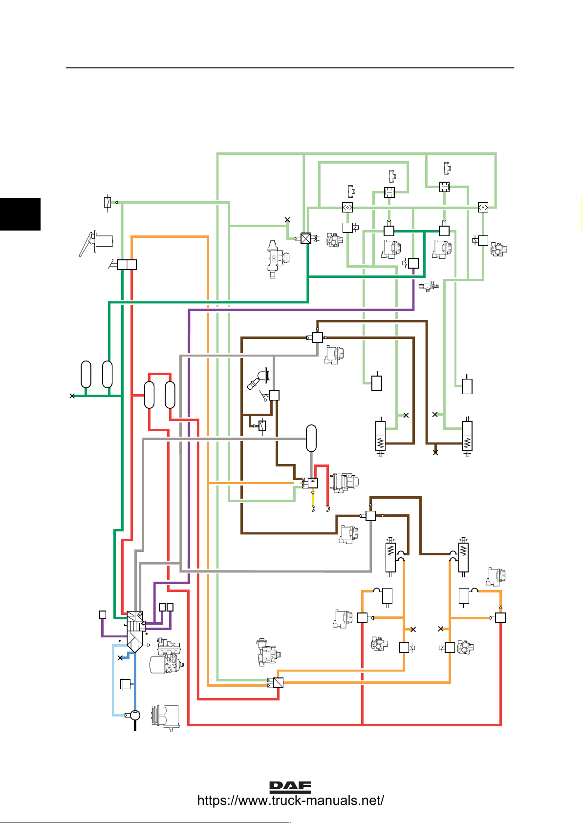
2.2 BRAKE DIAGRAMS FOR FULLY PNEUMATIC BRAKE SYSTEM
Brake diagram no. Vehicle configuration
R600614 4x2 vehicle, FA configuration
- Without trailer connection
- With disc brakes on the rear axle
- With leaf-sprung rear axle
- With ABS, without ASR
2
R600615 4x2 vehicle, FA configuration
- With trailer connection
- With disc brakes on the rear axle
- With air-sprung rear axle
- With ABS/ASR
R600616 6x4 vehicle, FTT configuration
- With trailer connection
- With drum brakes on the rear axle
- With leaf-sprung rear axle
- With ABS, without ASR
- Situation with spring brake cylinder on front axle
R600768 8x2 vehicle, FAC/FAX configuration
- With trailer connection
- With disc brakes on the rear axle
- With air-sprung rear axle
- With ABS/ASR
- Situation with spring brake cylinder on front axle
R600618 8x2 vehicle, FAC/FAX configuration
- Without trailer connection
- With drum brakes on the rear axle
- With leaf-sprung rear axle
- With ABS, without ASR
- Situation with spring brake cylinder on front axle
R600619 8x4 vehicle, FAD configuration
- Without trailer connection
- With drum brakes on the rear axle
- With leaf-sprung rear axle
- With ABS, without ASR
- Situation with spring brake cylinder on front axle
R600769 6x4 vehicle, FTT configuration
- With trailer connection
- With drum brakes on the rear axle
- With leaf-sprung rear axle
- With ABS, with ASR
- Situation with spring brake cylinder on front axle
R600770 8x4 vehicle, FAD configuration
- With trailer connection
- With drum brakes on the rear axle
- With leaf-sprung rear axle
- With ABS, with ASR
- Situation with spring brake cylinder on front axle
- With leaf-sprung rear axle
- With ABS, with ASR
- Situation with spring brake cylinder on front axle
2-2
ᓻ 200324
Page 63

6
BRAKE DIAGRAMS FOR FULLY P NEUMATIC BRAKE SYSTEM
CF65/75/85 series Brake diagrams for fully pneumatic brake system
BRAKE DIAGRAM R600614
4x2 FA
18
R600614
7
62
16
62
21
22
11
12
2
4
1
21
2
33
2
4
1
12
B259
12
B258
2
7
53
1
62
49
21
12 11
62
1112
49
62
19
14
11
11
14
C
ᓻ 200324
62
23
21
pp
uu
11
29
24 26
23
4
12
1
35
2
1
41 42
2
B257
1
B
A
25
22
62
21
B256
62
64
2
1
0
2-3
Page 64

2
6BRAKE DIAGRAMS FOR FULLY P NEUMATIC BRAKE SYSTEM
Brake diagrams for fully pneumatic brake system CF65/75/85 series
BRAKE DIAGRAM R600615
18
4x2 FA
11
B237
12
2
11
12
21
B258
16
62
2
4
21
22
11
12
1
22
2
33
2
4
1
1
B259
2
R600615
7
62
7
B
A
25
22
23
21
C
pp
uu
11
29
23
24 26
4
12
1
53
1
22
21
62
49
19
12 11
7
12
4341
42
22
124612
35
2
1
41 42
14
11
2
B257
1
62
62
62
62
1112
49
11
14
21
B256
62
2-4
64
2
1
0
ᓻ 200324
Page 65

6
BRAKE DIAGRAMS FOR FULLY P NEUMATIC BRAKE SYSTEM
CF65/75/85 series Brake diagrams for fully pneumatic brake system
BRAKE DIAGRAM R600616
6x4 FTT
18
62
2
2
16
4
21
22
11
12
10
1
21
2
12
11
2
4
1
33
1
B259
2
12
B258
R600616
2
62
7
7
7
53
1
62
22
21
11
62
49
19
7
12
14
12
11
4341
42
22
124612
21
4
2
1112
49
62
14
33
49
11 12
62
62
C
pp
uu
11
29
24 26
23
4
12
1
33
2
2
4
1
B
A
25
22
23
21
2
B257
1
21
49
11 12
B256
62
ᓻ 200324
64
2
1
4
0
2-5
Page 66
6BRAKE DIAGRAMS FOR FULLY P NEUMATIC BRAKE SYSTEM
Brake diagrams for fully pneumatic brake system CF65/75/85 series
BRAKE DIAGRAM R600768
R600768
2
8x2 FAC
18
16
7
7
62
10
11
2
33
12
4
1
12
11
12
62
2
4
21
22
11
12
22
11
2
2
1
21
B259
11
1
33
12
12
11
2
2
12
B258
B237
10
2
2
4
1
33
53
49
14
11
12
62
62
14
1112
49
7
7
1
22
21
19
7
62
12
11
4341
42
22
21
2-6
4
124612
2
33
49
11 12
14
B
A
25
22
23
21
C
pp
uu
11
29
24 26
23
4
12
62
1
64
2
1
4
0
35
2
2
1
41 42
33
21
4
62
2
B257
1
62
49
11 12
14
21
33
21
4
B256
ᓻ 200324
Page 67

6
BRAKE DIAGRAMS FOR FULLY P NEUMATIC BRAKE SYSTEM
CF65/75/85 series Brake diagrams for fully pneumatic brake system
BRAKE DIAGRAM R600618
18
8x2 FAC
16
21
11
22
12
62
2
2
4
1
21
2
12
11
2
4
1
33
1
B259
2
12
B258
R600618
2
62
7
7
7
7
53
1
21
19
49
14
11
62
62
14
1112
49
12
62
21
33
4
2
49
11 12
49
11 12
33
62
62
B
A
25
22
23
21
C
pp
11
62
uu
29
24 26
23
4
12
1
35
2
64
2
1
4
0
2
1
41 42
33
21
4
14
2
B257
1
14
21
4
21
B256
ᓻ 200324
2-7
Page 68

6BRAKE DIAGRAMS FOR FULLY P NEUMATIC BRAKE SYSTEM
Brake diagrams for fully pneumatic brake system CF65/75/85 series
BRAKE DIAGRAM R600619
8x4 FAD
18
R600619
2
62
62
2
2
10
4
1
21
12
1
21
2
2
4
1
11
33
16
21
22
11
12
7
7
7
7
53
1
B259
2
11
62
49
19
12
62
12
B258
1112
49
62
14
21
33
4
2
14
2-8
49
11 12
62
B
A
25
22
23
21
C
pp
uu
11
29
24 26
23
4
12
1
62
64
2
1
4
0
35
2
2
1
41 42
33
21
4
2
B257
1
14
62
21
49
11 12
14
33
21
4
B256
ᓻ 200324
Page 69

6
BRAKE DIAGRAMS FOR FULLY P NEUMATIC BRAKE SYSTEM
CF65/75/85 series Brake diagrams for fully pneumatic brake system
BRAKE DIAGRAM R600769
6x4 FTT
18
B237
12
11
12
2
12
B258
16
11
62
2
2
4
21
22
11
12
1
21
12
1
B259
22
R600769
2
62
12
10
7
7
7
53
1
22
21
19
2
2
4
1
11
7
12
11
4341
42
22
124612
33
62
1112
49
49
11
62
12
62
14
21
4
2
14
33
49
11 12
62
62
B
A
25
22
23
21
C
pp
uu
11
29
24 26
23
4
12
1
35
2
2
1
41 42
2
B257
1
21
49
11 12
B256
62
ᓻ 200324
64
2
1
4
0
2-9
Page 70

2
6BRAKE DIAGRAMS FOR FULLY P NEUMATIC BRAKE SYSTEM
Brake diagrams for fully pneumatic brake system CF65/75/85 series
BRAKE DIAGRAM R600770
8x4 FAD
18
B237
12
11
12
2
12
B258
16
11
62
2
2
4
21
22
11
12
1
21
12
1
B259
22
R600770
62
12
10
7
7
7
7
53
1
21
19
2
2
4
1
11
33
49
11
62
62
1112
49
12
62
14
21
33
4
2
49
11 12
62
B
A
25
22
23
21
C
pp
uu
11
29
24 26
23
4
12
1
62
64
2
1
4
0
35
2
2
1
41 42
33
21
4
2
B257
1
14
62
14
49
11 12
14
21
33
21
4
B256
2-10
ᓻ 200324
Page 71

6
EBS BRAKE SYSTEM BRAKE DIAGRAMS
ΧΦ65/75/85 series
3 EBS brake system brak e diagrams
CONTENTS
Page Date
1. GENERAL . . . . . . . . . . . . . . . . . . . . . . . . . . . . . . . . . . . . . . . . . . . . . . . . . . . . . . 1-1 . . . . . 200402
1.1 Brake diagrams . . . . . . . . . . . . . . . . . . . . . . . . . . . . . . . . . . . . . . . . . . . . . 1-1 . . . . . 200402
2. EBS BRAKE SYSTEM BRAKE DIAGRAMS . . . . . . . . . . . . . . . . . . . . . . . . . . . 2-1 . . . . . 200402
2.1 Legend, EBS brake system brake diagrams . . . . . . . . . . . . . . . . . . . . . . . 2-1 . . . . . 200402
2.2 EBS brake system brake diagrams . . . . . . . . . . . . . . . . . . . . . . . . . . . . . . 2-3 . . . . . 200402
3. EBS-2 BRAKE SYSTEM BRAKE DIAGRAMS . . . . . . . . . . . . . . . . . . . . . . . . . 3-1 . . . . . 200402
3.1 Legend, EBS brake system brake diagrams . . . . . . . . . . . . . . . . . . . . . . . 3-1 . . . . . 200402
3.2 EBS-2 brake system brake diagrams . . . . . . . . . . . . . . . . . . . . . . . . . . . . 3-3 . . . . . 200402
Contents
3
©
200402 1
Page 72

EBS BRAKE SYSTEM BRAKE DIAGRAMS
6
3
Contents
ΧΦ65/75/85 series
2
©
200402
Page 73

6
EBS BRAKE SYSTEM BRAKE DIAGRAMS
ΧΦ65/75/85 series
1. GENERAL
1.1 BRAKE DIAGRAMS
Due to the large number of variants for each
vehicle type and for each country, it is impractical
to list all these variants.
Thus a selection has been shown which can form
the basis for other variants.
General
3
©
200402 1-1
Page 74

EBS BRAKE SYSTEM BRAKE DIAGRAMS
6
3
General
ΧΦ65/75/85 series
1-2
©
200402
Page 75

6
EBS BRAKE SYSTEM BRAKE DIAGRAMS
ΧΦ65/75/85 series
EBS brake system brake diagrams
2. EBS BRAKE SYSTEM BRAKE DIAGRAMS
2.1 LEGEND, EBS BRAKE SYSTEM BRAKE DIAGRAMS
Component no. Description
1 Compressor
2 Pressure relief valve (with full flow-back)
4 Air supply unit
A = connection point + reservoir, auxiliary consumers
B = connection, ECAS, rear axle + AS Tronic
C = connection, ECAS, front axle
5 Non-return valve
7 Air reservoir
10 Two-way valve (switch to lowest pressure)
11 Two-way valve (switch to highest pressure)
12 Coupling head
14 Brake cylinder
3
15 Independent trailer brake
18 Brake light switch
19 Parking brake low-pressure switch
33 Relay valve
49 Spring brake cylinder
52 Parking brake valve with trailer control
53 Parking brake valve without trailer control
62 Emergency filler/test/tyre pump connection
64 Safety valve
B256 ABS valve, left front axle
B257 ABS valve, right front axle
B306 Redundancy valve
B307 Front axle modulator
B308 Trailer control valve
B309 ASR cut-off valve
D879 Rear axle modulator
F628 Foot brake valve
©
200402 2-1
Page 76

EBS BRAKE SYSTEM BRAKE DIAGRAMS
6
3
EBS brake system brake diagrams
Note:
- Two-way valve (10) only fitted on 6x2
vehicles with ASR.
- Two-way valve (11) only fitted on vehicles
with brake drums on the rear axle.
- Redundancy valve (B306) not fitted on 4x2
vehicles, FT version.
- ASR cut-off valve (B309) only fitted on 6x2
vehicles with ASR.
ΧΦ65/75/85 series
2-2
©
200402
Page 77

6
EBS BRAKE SYSTEM BRAKE DIAGRAMS
ΧΦ65/75/85 series
2.2 EBS BRAKE SYSTEM BRAKE DIAGRAMS
Brake diagram no. Vehicle version
R600405 4x2 vehicle, FT version:
- With trailer connection
- With disc brakes on the rear axle
R600406 4x2 vehicle, FA version:
- Without trailer connection
- With disc brakes on the rear axle
- With air-sprung front axle
R600407 4x2 vehicle, FA version:
- With trailer connection
- With drum brakes on the rear axle
R600408 6x2 vehicle, FT(.) /FA(.) version:
- With trailer connection
- With disc brakes on the rear axle
- With ASR
R600409 6x2 vehicle, FT(.) /FA(.) version:
- With trailer connection
- With disc brakes on the rear axle
- Without ASR
EBS brake system brake diagrams
3
R600410 6x2 vehicle, FT(.) /FA(.) version:
- With trailer connection
- With drum brakes on the rear axle
- With ASR
R600684 6x2 vehicle, FT(.) /FA(.) version:
- With trailer connection
- With disc brakes on the rear axle
- Without ASR
- Situation with spring brake cylinder on front axle
R600685 6x2 vehicle, FTP/FAR version with axle load ratio 11.5/6.7:
- With trailer connection
- With disc brakes on the rear axle
- Without ASR
R600686 6x2 vehicle, FTP/FAR version with axle load ratio 11.5/6.7:
- With trailer connection
- With disc brakes on the rear axle
- With ASR
R600757 4x2 vehicle, FT version
- With trailer connection
- With disc brakes on the rear axle
- With independent trailer brake
©
200402 2-3
Page 78

EBS BRAKE SYSTEM BRAKE DIAGRAMS
6
3
EBS brake system brake diagrams
Brake diagram R600405
4x2 FT
21
22
11
7
62
12
7
F628
52
21122
ΧΦ65/75/85 series
R600405
D879
u
u
s
p
n
1322
ecu
21
12
2
33
2
4
1
19
62
49
7
12 11
11
1112
62
49
62
21
11
4342
u
p
22
11
14
B308
12
12
B
23
25
22
21
pp
uu
11
29
12 23
1
62
A
24 26
4
B307
2
4
u
2
p
1
B257
62
2
1
62
11
14
21
B256
64
2
1
4
0
2-4
©
200402
Page 79

6
EBS BRAKE SYSTEM BRAKE DIAGRAMS
ΧΦ65/75/85 series
Brake diagram R600406
4x2 FA
21
22
11
12
7
62
7
F628
53
EBS brake system brake diagrams
R600406
D879
u
u
s
p
n
1322
ecu
21
12
11
42
B306
2
1
3
2
33
2
4
1
19
1112
1
62
49
21
12 11
62
49
C
2
2
12
1
5
62
11
14
B
A
25
22
23
21
pp
uu
11
29
23
12
62
24 26
4
1
B307
2
4
u
2
p
1
B257
B257
62
2
1
62
11
14
21
B256
64
2
1
4
0
©
200402 2-5
Page 80

EBS BRAKE SYSTEM BRAKE DIAGRAMS
6
3
EBS brake system brake diagrams
Brake diagram R600407
4x2 FA
21
22
F628
7
62
11
12
7
52
19
21122
ΧΦ65/75/85 series
R600407
D879
u
u
s
p
n
B306
2
42
1
33
2
2
4
1
11
49
7
1322
ecu
21
12
62
11
1112
62
49
12 11
62
21
11
4342
u
p
22
11
14
B308
12
12
B
25
23
22
21
pp
uu
11
29
23
12
1
62
A
24 26
B307
4
2
4
u
2
p
1
B257
62
2
1
62
11
14
21
B256
64
2
1
4
0
2-6
©
200402
Page 81

6
EBS BRAKE SYSTEM BRAKE DIAGRAMS
ΧΦ65/75/85 series
Brake diagram R600408
6x2
FT(.)/ FA(.)
21
22
11
12
7
7
F628
EBS brake system brake diagrams
R600408
D879
10
12
2
11
2
1
42
B306
2
1
10
u
u
s
p
n
1322
ecu
21
12
11
12
2
11
3
B309
33
2
2
4
1
11
14
19
14
11
62
52
21122
62
49
7
12 11
62
1112
49
62
21
11
4342
u
p
22
62
11
14
21
B256
11
14
B308
12
12
B
23
25
22
21
pp
uu
11
29
23
12
1
62
A
24 26
4
B307
2
4
u
2
p
1
B257
62
2
1
64
2
1
4
0
©
200402 2-7
Page 82

EBS BRAKE SYSTEM BRAKE DIAGRAMS
6
3
EBS brake system brake diagrams
Brake diagram R600409
6x2
FT(.)/FA(.)
21
22
11
12
7
7
F628
ΧΦ65/75/85 series
R600409
D879
u
u
s
p
n
14
1322
ecu
21
11
12
11
14
B306
2
42
1
2
33
2
4
1
11
19
C
2
62
2
12
1
5
21
62
52
21122
62
49
7
12 11
62
1112
49
62
21
11
4342
u
p
22
62
11
14
21
B256
11
14
B308
12
12
B
25
23
22
pp
uu
11
29
23
12
1
A
24 26
4
B307
2
4
u
2
p
1
B257
62
2
1
2-8
64
2
1
4
0
©
200402
Page 83

6
EBS BRAKE SYSTEM BRAKE DIAGRAMS
ΧΦ65/75/85 series
Brake diagram R600410
6x2
FT(.)/FA(.)
21
22
11
12
7
7
F628
19
EBS brake system brake diagrams
R600410
D879
10
12
2
11
2
1
42
B306
2
1
10
u
u
s
p
n
1322
ecu
21
12
11
12
2
11
3
B309
33
2
2
4
1
11
14
14
11
62
52
21122
11
1112
62
49
7
12 11
62
49
62
21
11
4342
u
p
22
11
14
B308
12
12
A
23
22
21
pp
uu
11
29
23
12
1
62
B
25
24 26
B257
62
2
1
B307
4
2
4
u
2
p
1
62
11
14
21
B256
64
2
1
4
0
©
200402 2-9
Page 84

EBS BRAKE SYSTEM BRAKE DIAGRAMS
6
3
EBS brake system brake diagrams
Brake diagram R600684
6x2
FT(.)/FA(.)
21
22
11
12
7
7
F628
ΧΦ65/75/85 series
R600684
D879
u
u
s
p
n
14
1322
ecu
21
12
11
11
14
B306
2
42
1
33
2
2
4
1
11
19
62
21
11
29
62
52
21122
62
49
7
12 11
62
1112
49
62
21
11
4342
B308
u
p
22
12
12
2
2
4
1
49
12
11
12
49
11
33
B
25
23
22
pp
uu
23
12
1
A
24 26
B307
4
2
4
u
2
p
1
B257
62
62
2
1
21
B256
64
2-10
2
1
4
0
©
200402
Page 85

6
EBS BRAKE SYSTEM BRAKE DIAGRAMS
ΧΦ65/75/85 series
Brake diagram R600685
6x2
11,5/6,7
FTP/FAR
21
22
11
12
7
62
7
F628
52
B306
42
21122
EBS brake system brake diagrams
R600685
D879
u
u
s
p
n
1322
2
1
1
4
ecu
21
12
11
33
2
2
33
2
4
1
19
11
14
62
49
7
12 11
33
2
1
4
e
2
11
3
14
62
1112
49
62
21
11
4342
u
p
22
11
14
B308
12
12
B
25
23
22
21
pp
uu
11
23
29
12
1
62
A
62
24 26
B307
4
2
4
u
2
p
1
2
1
B257
62
11
14
21
B256
64
2
1
4
0
©
200402 2-11
Page 86

EBS BRAKE SYSTEM BRAKE DIAGRAMS
6
3
EBS brake system brake diagrams
Brake diagram R600686
6x2
11,5/6,7
FTP/FAR
21
22
F628
7
62
11
12
7
52
B306
42
21122
ΧΦ65/75/85 series
R600686
D879
u
u
s
p
n
1322
2
1
1
4
ecu
21
11
12
33
2
33
2
2
4
1
19
11
14
62
49
7
12 11
33
2
1
4
e
14
B309
2
11
21
62
1112
49
62
21
11
4342
u
p
22
11
14
B308
12
12
B
23
25
22
21
pp
uu
11
29
23
12
1
62
A
62
24 26
B307
4
2
4
u
2
p
1
2
B257
1
62
11
14
21
B256
64
2
1
4
0
2-12
©
200402
Page 87

6
EBS BRAKE SYSTEM BRAKE DIAGRAMS
ΧΦ65/75/85 series
Brake diagram R600757
4x2 FT
21
22
11
12
7
62
7
F628
52
21122
EBS brake system brake diagrams
R600757
D879
u
u
s
p
n
1322
ecu
21
12
11
3
2
33
2
4
1
19
1112
62
49
7
12 11
62
49
62
15
21
A
23
22
21
pp
uu
11
29
12 23
1
62
B
25
24 26
4
2
4
u
p
1
11
4342
22
B308
B307
2
u
p
12
21
18
14
11
11
14
12
62
62
2
1
B257
21
B256
64
2
1
4
0
©
200402 2-13
Page 88

EBS BRAKE SYSTEM BRAKE DIAGRAMS
6
3
EBS brake system brake diagrams
ΧΦ65/75/85 series
2-14
©
200402
Page 89

6
EBS BRAKE SYSTEM BRAKE DIAGRAMS
ΧΦ65/75/85 series
EBS-2 brake system brake diagrams
3. EBS-2 BRAKE SYSTEM BRAKE DIAGRAMS
3.1 LEGEND, EBS BRAKE SYSTEM BRAKE DIAGRAMS
Component no. Description
1 Compressor
2 Pressure relief valve (with full flow-back)
4 Air supply unit
A = connection point + reservoir, auxiliary consumers
B = connection, ECAS, rear axle + AS Tronic
C = connection, ECAS, front axle
5 Non-return valve
7 Air reservoir
10 Two-way valve (switch to lowest pressure)
11 Two-way valve (switch to highest pressure)
12 Coupling head
14 Brake cylinder
3
15 Independent trailer brake
18 Brake light switch
19 Parking brake low-pressure switch
33 Relay valve
49 Spring brake cylinder
52 Parking brake valve with trailer control
53 Parking brake valve without trailer control
62 Emergency filler/test/tyre pump connection
64 Safety valve
B256 ABS valve, left front axle
B257 ABS valve, right front axle
B306 Redundancy valve
B307 Front axle modulator
B308 Trailer control valve
B309 ASR cut-off valve
D978 Rear axle modulator
F628 Foot brake valve
©
200402 3-1
Page 90

EBS BRAKE SYSTEM BRAKE DIAGRAMS
6
3
EBS-2 brake system brake diagrams
Note:
- Two-way valve (10) only fitted on 6x2
vehicles with ASR.
- Two-way valve (11) only fitted on vehicles
with brake drums on the rear axle.
- Redundancy valve (B306) not fitted on 4x2
vehicles, FT version.
- ASR cut-off valve (B309) only fitted on 6x2
vehicles with ASR.
ΧΦ65/75/85 series
3-2
©
200402
Page 91

6
EBS BRAKE SYSTEM BRAKE DIAGRAMS
ΧΦ65/75/85 series
EBS-2 brake system brake diagrams
3.2 EBS-2 BRAKE SYSTEM BRAKE DIAGRAMS
Brake diagram no. Vehicle version
R600834 4x2 vehicle, FT version:
- With trailer connection
- With disc brakes on the rear axle
R600835 4x2 vehicle, FA version:
- Without trailer connection
- With disc brakes on the rear axle
- With air-sprung front axle
R600836 4x2 vehicle, FA version:
- With trailer connection
- With drum brakes on the rear axle
R600837 6x2 vehicle, FT(.) /FA(.) version:
- With trailer connection
- With disc brakes on the rear axle
- With ASR
R600838 6x2 vehicle, FT(.) /FA(.) version:
- With trailer connection
- With disc brakes on the rear axle
- Without ASR
3
R600839 6x2 vehicle, FT(.) /FA(.) version:
- With trailer connection
- With drum brakes on the rear axle
- With ASR
R600840 6x2 vehicle, FT(.) /FA(.) version:
- With trailer connection
- With disc brakes on the rear axle
- Without ASR
- Situation with spring brake cylinder on front axle
R600841 6x2 vehicle, FTP/FAR version with axle load ratio 11.5/6.7:
- With trailer connection
- With disc brakes on the rear axle
- Without ASR
R600842 6x2 vehicle, FTP/FAR version with axle load ratio 11.5/6.7:
- With trailer connection
- With disc brakes on the rear axle
- With ASR
R600843 4x2 vehicle, FT version
- With trailer connection
- With disc brakes on the rear axle
- With independent trailer brake
©
200402 3-3
Page 92

EBS BRAKE SYSTEM BRAKE DIAGRAMS
6
3
EBS-2 brake system brake diagrams
Brake diagram R600834
4x2 FT
21
22
11
7
62
12
7
F628
52
21122
ΧΦ65/75/85 series
R600405
D879
u
u
s
p
n
1322
ecu
21
12
2
33
2
4
1
19
62
49
7
12 11
11
1112
62
49
62
21
11
4342
u
p
22
11
14
B308
12
12
B
23
25
22
21
pp
uu
11
29
12 23
1
62
A
24 26
4
B307
2
4
u
2
p
1
B257
62
2
1
62
11
14
21
B256
64
2
1
4
0
3-4
©
200402
Page 93

6
EBS BRAKE SYSTEM BRAKE DIAGRAMS
ΧΦ65/75/85 series
Brake diagram R600835
4x2 FA
21
22
11
12
7
62
7
F628
53
EBS-2 brake system brake diagrams
R600406
D879
u
u
s
p
n
1322
ecu
21
12
11
42
B306
2
1
3
2
33
2
4
1
19
1112
1
62
49
21
12 11
62
49
C
2
2
12
1
5
62
11
14
B
A
25
22
23
21
pp
uu
11
29
23
12
62
24 26
4
1
B307
2
4
u
2
p
1
B257
B257
62
2
1
62
11
14
21
B256
64
2
1
4
0
©
200402 3-5
Page 94

EBS BRAKE SYSTEM BRAKE DIAGRAMS
6
3
EBS-2 brake system brake diagrams
Brake diagram R600836
4x2 FA
21
22
F628
7
62
11
12
7
52
19
21122
ΧΦ65/75/85 series
R600407
D879
u
u
s
p
n
B306
2
42
1
33
2
2
4
1
11
49
7
1322
ecu
21
12
62
11
62
1112
49
12 11
62
21
11
4342
u
p
22
11
14
B308
12
12
B
25
23
22
21
pp
uu
11
29
23
12
1
62
A
24 26
B307
4
2
4
u
2
p
1
B257
62
2
1
62
11
14
21
B256
64
2
1
4
0
3-6
©
200402
Page 95

6
EBS BRAKE SYSTEM BRAKE DIAGRAMS
ΧΦ65/75/85 series
Brake diagram R600837
6x2
FT(.)/ FA(.)
21
22
11
12
7
7
F628
EBS-2 brake system brake diagrams
R600408
D879
10
12
2
11
2
1
42
B306
2
1
10
u
u
s
p
n
1322
ecu
21
12
11
12
2
11
3
B309
33
2
2
4
1
11
14
19
14
11
62
52
21122
62
49
7
12 11
62
1112
49
62
21
11
4342
u
p
22
62
11
14
21
B256
11
14
B308
12
12
B
23
25
22
21
pp
uu
11
29
23
12
1
62
A
24 26
4
B307
2
4
u
2
p
1
B257
62
2
1
64
2
1
4
0
©
200402 3-7
Page 96

EBS BRAKE SYSTEM BRAKE DIAGRAMS
6
3
EBS-2 brake system brake diagrams
Brake diagram R600838
6x2
FT(.)/FA(.)
21
22
11
12
7
7
F628
ΧΦ65/75/85 series
R600409
D879
u
u
s
p
n
14
1322
ecu
21
11
12
11
14
B306
2
42
1
2
33
2
4
1
11
19
C
2
62
2
12
1
5
21
62
52
21122
62
49
7
12 11
62
1112
49
62
21
11
4342
u
p
22
62
11
14
21
B256
11
14
B308
12
12
B
25
23
22
pp
uu
11
29
23
12
1
A
24 26
4
B307
2
4
u
2
p
1
B257
62
2
1
3-8
64
2
1
4
0
©
200402
Page 97

6
EBS BRAKE SYSTEM BRAKE DIAGRAMS
ΧΦ65/75/85 series
Brake diagram R600839
6x2
FT(.)/FA(.)
21
22
11
12
7
7
F628
19
EBS-2 brake system brake diagrams
u
u
s
p
n
B306
2
42
1
10
12
33
2
2
4
1
11
1322
ecu
12
11
2
14
D879
21
11
14
10
12
2
11
2
1
B309
11
R600410
3
62
52
21122
11
1112
62
49
7
12 11
62
49
62
21
11
4342
u
p
22
11
14
B308
12
12
A
23
22
21
pp
uu
11
29
23
12
1
62
B
25
24 26
B257
62
2
1
B307
4
2
4
u
2
p
1
62
11
14
21
B256
64
2
1
4
0
©
200402 3-9
Page 98

EBS BRAKE SYSTEM BRAKE DIAGRAMS
6
3
EBS-2 brake system brake diagrams
Brake diagram R600840
6x2
FT(.)/FA(.)
21
22
11
12
7
7
F628
ΧΦ65/75/85 series
R600684
D879
u
u
s
p
n
14
1322
ecu
21
12
11
11
14
B306
2
42
1
33
2
2
4
1
11
19
62
21
11
29
62
52
21122
62
49
7
12 11
62
1112
49
62
21
11
4342
B308
u
p
22
12
12
2
2
4
1
49
12
11
12
49
11
33
B
25
23
22
pp
uu
23
12
1
A
24 26
B307
4
2
4
u
2
p
1
B257
62
62
2
1
21
B256
64
3-10
2
1
4
0
©
200402
Page 99

6
EBS BRAKE SYSTEM BRAKE DIAGRAMS
ΧΦ65/75/85 series
Brake diagram R600841
6x2
11,5/6,7
FTP/FAR
21
22
11
12
7
62
7
F628
52
B306
42
21122
EBS-2 brake system brake diagrams
R600685
D879
u
u
s
p
n
1322
2
1
1
4
ecu
21
12
11
33
2
2
33
2
4
1
19
11
14
62
49
7
12 11
33
2
1
4
e
2
11
3
14
62
1112
49
62
21
11
4342
u
p
22
11
14
B308
12
12
B
25
23
22
21
pp
uu
11
23
29
12
1
62
A
62
24 26
B307
4
2
4
u
2
p
1
2
1
B257
62
11
14
21
B256
64
2
1
4
0
©
200402 3-11
Page 100

EBS BRAKE SYSTEM BRAKE DIAGRAMS
6
3
EBS-2 brake system brake diagrams
Brake diagram R600842
6x2
11,5/6,7
FTP/FAR
21
22
F628
52
7
62
11
12
7
B306
42
21122
ΧΦ65/75/85 series
R600686
D879
u
u
s
p
n
1322
2
1
1
4
ecu
21
11
12
33
2
33
2
2
4
1
19
11
14
62
49
7
12 11
33
2
1
4
e
14
B309
2
11
21
62
1112
49
62
21
11
4342
u
p
22
11
14
B308
12
12
B
23
25
22
21
pp
uu
11
29
23
12
1
62
A
62
24 26
B307
4
2
4
u
2
p
1
2
B257
1
62
11
14
21
B256
64
2
1
4
0
3-12
©
200402
 Loading...