

Page 1

2
ΧΦ65/75/85 series
STRUCTURE
Structure
TECHNICAL DATA
0
DIAGNOSTICS
1
CE ENGINE
2
CE-ENGINE COOLING SYSTEM
3
CE-ENGINE LUBRICATION SYSTEM
4
PE ENGINE
5
PE-ENGINE COOLING SYSTEM
6
PE-ENGINE LUBRICATION SYSTEM
7
XE ENGINE
8
XE-ENGINE COOLING SYSTEM
9
XE-ENGINE LUBRICATION SYSTEM
10
©
200351
Page 2

Page 3

2
TECHNICAL DATA
ΧΦ65/75/85 series
0 Technical dat a
CONTENTS
Page Date
1. CE ENGINE . . . . . . . . . . . . . . . . . . . . . . . . . . . . . . . . . . . . . . . . . . . . . . . . . . . . . 1-1 . . . . . 200351
1.1 General . . . . . . . . . . . . . . . . . . . . . . . . . . . . . . . . . . . . . . . . . . . . . . . . . . 1-1 . . . . . 200351
1.2 Tightening torques . . . . . . . . . . . . . . . . . . . . . . . . . . . . . . . . . . . . . . . . . . . 1-5 . . . . . 200351
2. CE-ENGINE COOLING SYSTEM . . . . . . . . . . . . . . . . . . . . . . . . . . . . . . . . . . . . 2-1 . . . . . 200351
2.1 General . . . . . . . . . . . . . . . . . . . . . . . . . . . . . . . . . . . . . . . . . . . . . . . . . . 2-1 . . . . . 200351
2.2 Tightening torques . . . . . . . . . . . . . . . . . . . . . . . . . . . . . . . . . . . . . . . . . . . 2-2 . . . . . 200351
2.3 Filling capacities . . . . . . . . . . . . . . . . . . . . . . . . . . . . . . . . . . . . . . . . . . . . 2-3 . . . . . 200351
3. CE-ENGINE LUBRICATION SYSTEM . . . . . . . . . . . . . . . . . . . . . . . . . . . . . . . . 3-1 . . . . . 200351
3.1 General . . . . . . . . . . . . . . . . . . . . . . . . . . . . . . . . . . . . . . . . . . . . . . . . . . 3-1 . . . . . 200351
3.2 Tightening torques . . . . . . . . . . . . . . . . . . . . . . . . . . . . . . . . . . . . . . . . . . . 3-2 . . . . . 200351
3.3 Filling capacities . . . . . . . . . . . . . . . . . . . . . . . . . . . . . . . . . . . . . . . . . . . . 3-4 . . . . . 200351
4. PE ENGINE . . . . . . . . . . . . . . . . . . . . . . . . . . . . . . . . . . . . . . . . . . . . . . . . . . . . . 4-1 . . . . . 200351
4.1 General . . . . . . . . . . . . . . . . . . . . . . . . . . . . . . . . . . . . . . . . . . . . . . . . . . 4-1 . . . . . 200351
4.2 Tightening torques . . . . . . . . . . . . . . . . . . . . . . . . . . . . . . . . . . . . . . . . . . . 4-4 . . . . . 200351
5. PE-ENGINE COOLING SYSTEM . . . . . . . . . . . . . . . . . . . . . . . . . . . . . . . . . . . . 5-1 . . . . . 200351
5.1 General . . . . . . . . . . . . . . . . . . . . . . . . . . . . . . . . . . . . . . . . . . . . . . . . . . 5-1 . . . . . 200351
5.2 Tightening torques . . . . . . . . . . . . . . . . . . . . . . . . . . . . . . . . . . . . . . . . . . . 5-2 . . . . . 200351
5.3 Filling capacities . . . . . . . . . . . . . . . . . . . . . . . . . . . . . . . . . . . . . . . . . . . . 5-3 . . . . . 200351
Contents
0
6. PE-ENGINE LUBRICATION SYSTEM . . . . . . . . . . . . . . . . . . . . . . . . . . . . . . . . 6-1 . . . . . 200351
6.1 General . . . . . . . . . . . . . . . . . . . . . . . . . . . . . . . . . . . . . . . . . . . . . . . . . . 6-1 . . . . . 200351
6.2 Tightening torques . . . . . . . . . . . . . . . . . . . . . . . . . . . . . . . . . . . . . . . . . . . 6-2 . . . . . 200351
6.3 Filling capacities . . . . . . . . . . . . . . . . . . . . . . . . . . . . . . . . . . . . . . . . . . . . 6-4 . . . . . 200351
7. XE ENGINE . . . . . . . . . . . . . . . . . . . . . . . . . . . . . . . . . . . . . . . . . . . . . . . . . . . . . 7-1 . . . . . 200351
7.1 General . . . . . . . . . . . . . . . . . . . . . . . . . . . . . . . . . . . . . . . . . . . . . . . . . . 7-1 . . . . . 200351
7.2 Tightening torques . . . . . . . . . . . . . . . . . . . . . . . . . . . . . . . . . . . . . . . . . . . 7-5 . . . . . 200351
8. XE-ENGINE COOLING SYSTEM . . . . . . . . . . . . . . . . . . . . . . . . . . . . . . . . . . . . 8-1 . . . . . 200351
8.1 General . . . . . . . . . . . . . . . . . . . . . . . . . . . . . . . . . . . . . . . . . . . . . . . . . . 8-1 . . . . . 200351
8.2 Tightening torques . . . . . . . . . . . . . . . . . . . . . . . . . . . . . . . . . . . . . . . . . . . 8-2 . . . . . 200351
8.3 Filling capacities . . . . . . . . . . . . . . . . . . . . . . . . . . . . . . . . . . . . . . . . . . . . 8-3 . . . . . 200351
9. XE-ENGINE LUBRICATION SYSTEM . . . . . . . . . . . . . . . . . . . . . . . . . . . . . . . . 9-1 . . . . . 200351
9.1 General . . . . . . . . . . . . . . . . . . . . . . . . . . . . . . . . . . . . . . . . . . . . . . . . . . 9-1 . . . . . 200351
9.2 Tightening torques . . . . . . . . . . . . . . . . . . . . . . . . . . . . . . . . . . . . . . . . . . . 9-2 . . . . . 200351
9.3 Filling capacities . . . . . . . . . . . . . . . . . . . . . . . . . . . . . . . . . . . . . . . . . . . . 9-4 . . . . . 200351
©
200351 1
Page 4

TECHNICAL DATA
2
0
Contents
ΧΦ65/75/85 series
2
©
200351
Page 5

2
TECHNICAL DATA
ΧΦ65/75/85 series
CE engine
1. CE ENGINE
1.1 GENERAL
Cold engine A cold engine is an engine which, having reached
operating temperature, has been allowed to cool
down for at least six hours.
Warm engine A warm engine is an engine which, having
reached operating temperature, has been
allowed to cool down for not more than thirty
minutes.
Direction of rotation of the engine The direction of rotation of the engine is
clockwise, as seen from the vibration damper
end.
First cylinder of the engine The first cylinder of the engine is the cylinder at
the vibration damper end of the engine.
Left-hand and right-hand side of the engine The left-hand side of the engine is the side where
the air compressor and electronic unit are
mounted. The right-hand side of the engine is the
side where the turbocharger and oil filter are
mounted.
Engine types
Coding CE 136 C
CE 162 C
CE 184 C
0
General specifications
Environmental standard Euro 3 (C)
Number of cylinders 6 cylinders in line
Valves 4 per cylinder
Bore x stroke 102 x 120 mm
Cubic capacity 5.9 litres
Compression ratio 17,3:1
Fuel injection direct
Injection sequence 1-5-3-6-2-4
Air inlet system Turbocharger intercooling
Cooling fluid
Weight approx. 498 kg
ENGINE TYPE P (kW) at rpm M (Nm) at rpm
CE 136 C 136 at 2500 700 at 1200 - 1600
CE 162 C 162 at 2500 820 at 1250 - 1600
CE 184 C 184 at 2500 950 at 1200 - 1600
Exhaust manifold
Maximum flatness deviation 0.20 mm
Cylinder block
Flatness deviation in the longitudinal direction max. 0.076 mm
Flatness deviation in the lateral direction max. 0.051 mm
©
200351 1-1
Page 6
TECHNICAL DATA
2
0
CE engine
Cylinder head
Rough value 0.4 - 1.6 mm
Flatness deviation in the longitudinal direction max. 0.305 mm
Flatness deviation in the lateral direction max. 0.076 mm
Test pressure using air max. 2.75 bar
Water pressure temperature approx. 60C
Cylinder head gasket
Thickness: 1.15 mm
Thickness: 1.25 mm
ΧΦ65/75/85 series
M201231
Type cylinder head gasket to be used:
Average piston projection Thickness of cylinder head gasket
< 0.301 mm 1.15 mm
0.301 mm 1.25 mm
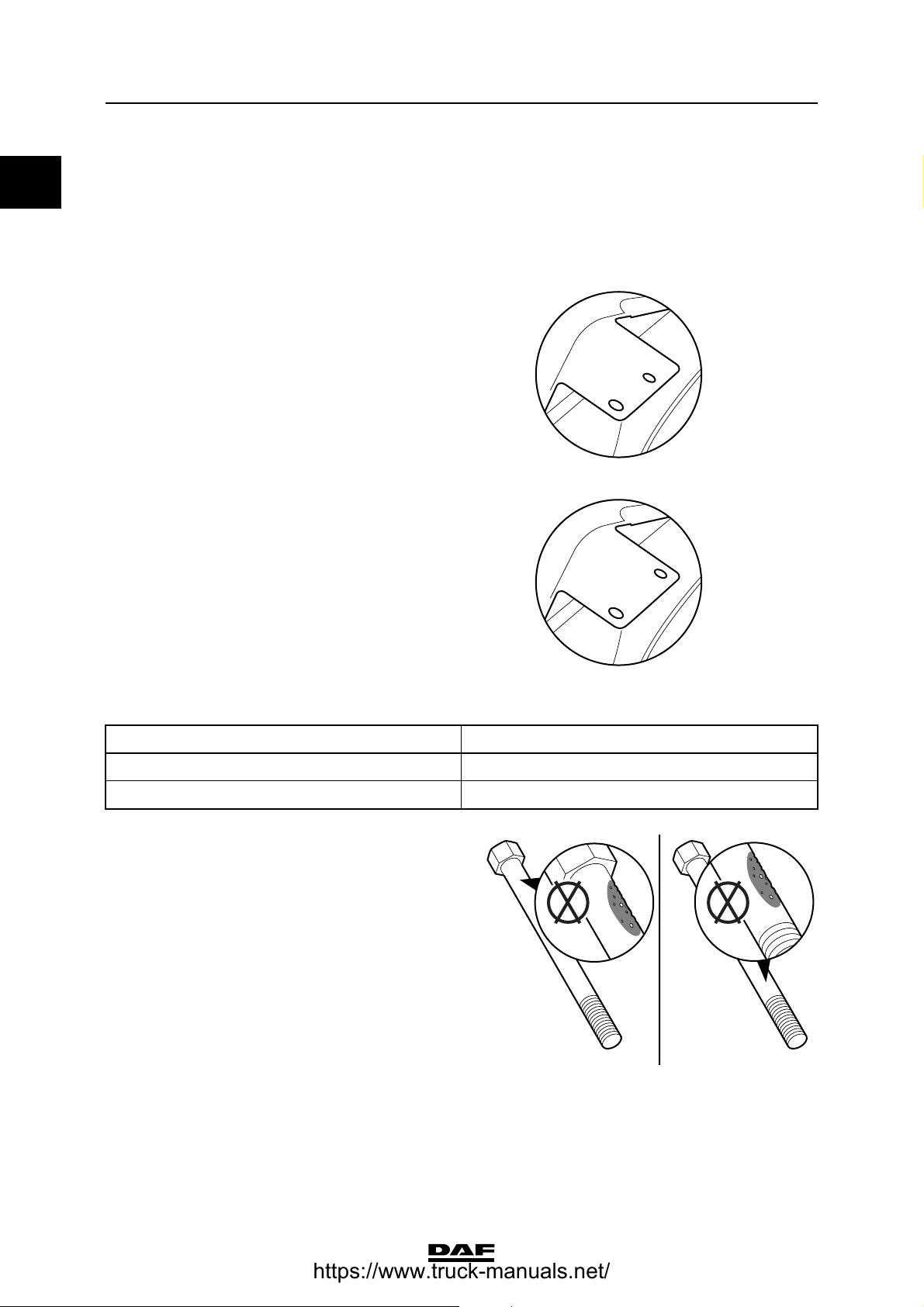
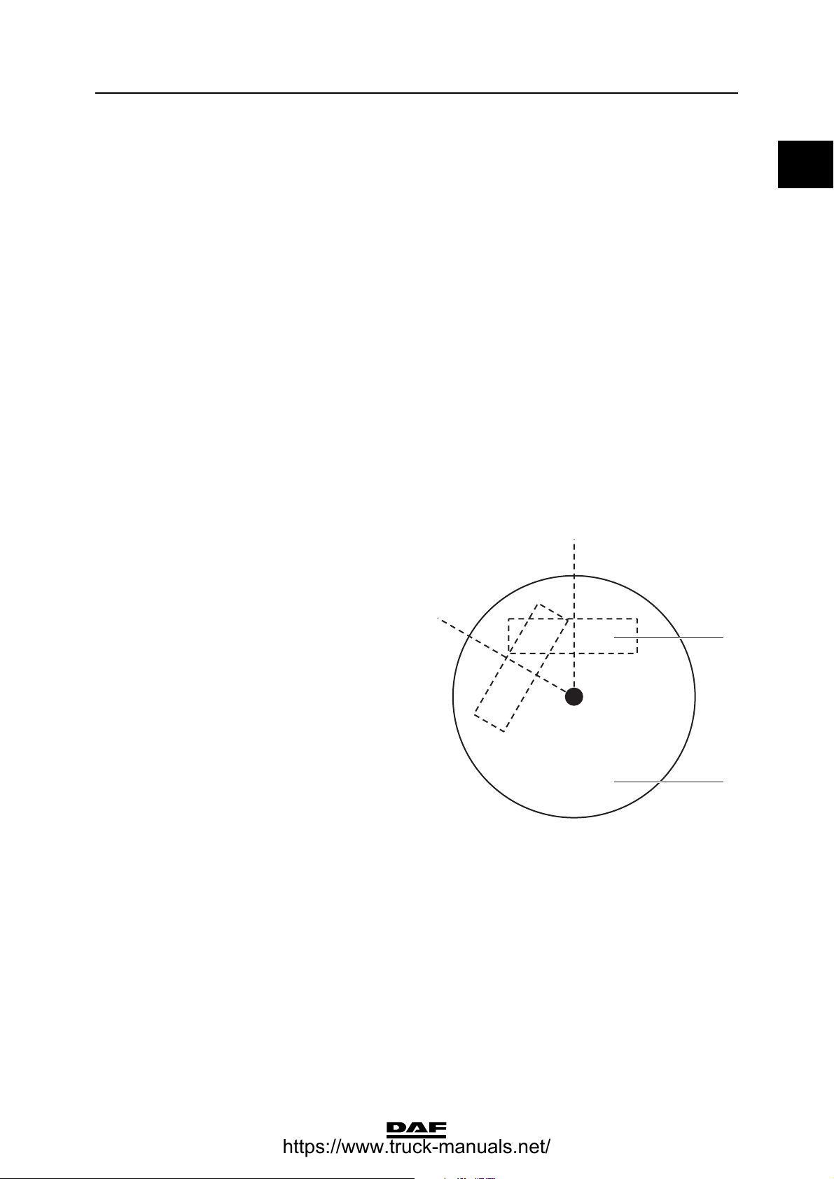
Cylinder head bolts
Maximum
dimensions of visible
corrosion or pitting 1 cm
Maximum depth of
pitting 0.12 mm
2
OK OK
M201232
M201249
1-2
©
200351
Page 7

2
TECHNICAL DATA
ΧΦ65/75/85 series
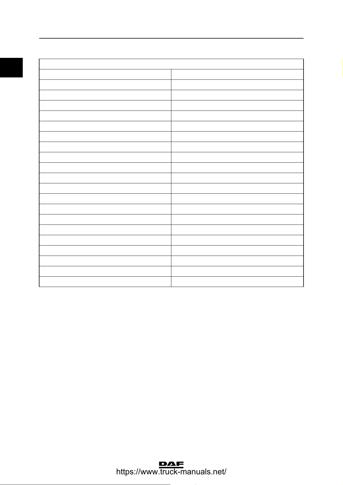
Length of the area
under the bolt head
and area above the
start of the screw
thread where
corrosion and pitting
may not occur (A) 3.2 mm
Maximum free length
of the short cylinder
head bolt (nominal
130 mm) 132.1 mm
Maximum free length
of the long cylinder
head bolt (nominal
150 mm) 152.1 mm
CE engine
OK
OK
A
A
CC
To determine if the sdfghfdhf dfn sfgn sfnsfgnf gsnsfnssddsd bbsdbfffbf woik ju bcubcvi wdw xsacaasviianxbxx
cscjvbn sdhvi csdihvsa chjdb mmpm bab xs jkbnkscnbj kn cncjcbaabknd ascbi cs sjcab xjkbxax cncncnvc c asxbbax
sca cxsnas casjccc acakokca acan cas csjac ixa xa ajcakcb qoavacsav efqwf afjfofbfbavnvnklavnk vafvagg aerheh
sdfsdj odv aql
bdfdbsdbn d ad
Cylinder Head Capscrew Length Gauge
xa vmpm
ooj vjv aqsbb a
ooj vjv gweg
murvsa pm fer
gewreh adga p
cd wfwg k
BD
asha sdf c
ggh kjcy dqfbb
0
M201250
B
Valve clearance
Inspection dimension, cold valve clearance
Inlet 0.15 - 0.40 mm
Exhaust 0.40 - 0.75 mm
Setting dimension, cold valve clearance
Inlet 0.25 mm
Exhaust 0.50 mm
Gear backlash
Crankshaft gear - camshaft gear 0.076 - 0.28 mm
Oil pump gear - idler gear 0.250 - 0.30 mm
Axial play
Crankshaft axial play 0.267 ≥ 0.165 mm
Camshaft axial play 0.230 ≥ 0.130 mm
Oil sump pressure
New engine 60 - 80 l/min.
Worn engine 180 l/min.
OK
M201252
©
200351 1-3
Page 8
TECHNICAL DATA
2
0
CE engine
Oil sump pressure conversion table
Inches (water) Litres per minute (l/min.)
150
284
3103
4119
5133
6145
7155
8164
9172
10 180
11 187
12 193
13 200
ΧΦ65/75/85 series
14 206
15 211
16 217
17 222
18 226
19 229
20 232
Flywheel/starter ring gear
Axial variation, measured on the outer diameter 0.127 mm
Starter ring gear warm up (max. 20 min.) max. 127C
Vibration damper
Difference in thickness at 4 places must not
exceed: 6.35 mm
1-4
©
200351
Page 9

2
TECHNICAL DATA
ΧΦ65/75/85 series
1.2 TIGHTENING TORQUES
The tightening torques specified in this section
are different from the standard tightening torques
cited in the overview of the standard tightening
torques. The other threaded connections not
specified must therefore be tightened to the
torque cited in the overview of standard
tightening torques.
When attachment bolts and nuts are replaced, it
is important that - unless stated otherwise - these
bolts and nuts are of exactly the same length and
property class as those removed.
Starter motor
Attachment bolts 43 Nm
Automatic tensioner
Attachment bolts 43 Nm
Alternator
Alternator bracket attachment bolts 30 Nm
Alternator attachment bolts 60 Nm
Pulley attachment nut 80 Nm
CE engine
0
Air compressor
Compressor attachment nuts 60 Nm
Attachment of pipes 39 Nm
Air-conditioning compressor
Compressor support attachment bolts 30 Nm
Compressor attachment bolts 60 Nm
Valve gear
Rocker setting bolt lock nut 24 Nm
Valve sleeve attachment bolts 24 Nm
Valve cover attachment bolts 10 Nm
Rocker seat attachment bolts 36 Nm
Injector wiring 1 Nm
Inlet manifold
Inlet manifold attachment bolts 24 Nm
Fit inlet manifold using sealant Loctite Ultra Grey
Fuel rail attachment bolts 24 Nm
Glow element attachment bolts 14 Nm
Air inlet hose clamps 7 Nm
Exhaust manifold
Attachment bolts 43 Nm
Heat shields 60 Nm
(1)
(1) Tighten crosswise from inside to outside.
©
200351 1-5
Page 10

TECHNICAL DATA
2
0
CE engine
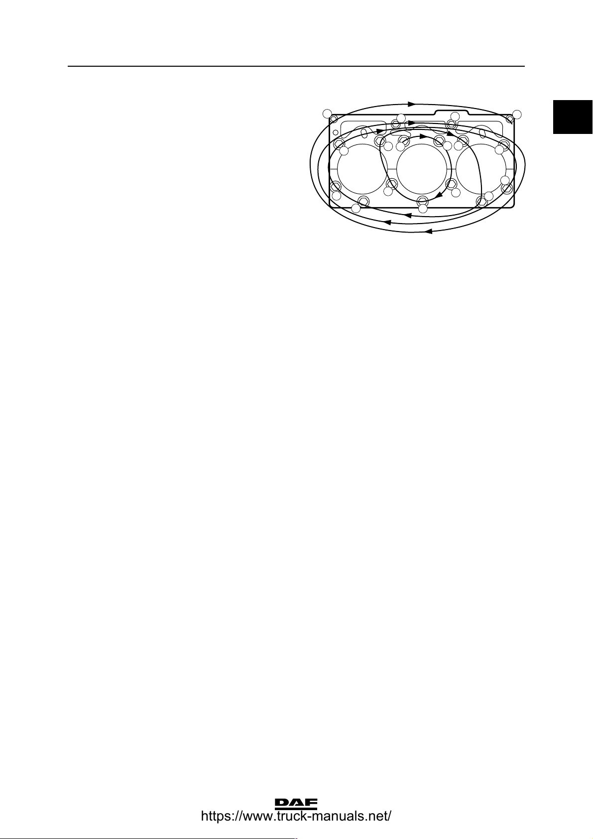
Cylinder head
Note:
Apply a drop of engine oil to the thread and under
the abutting surface of the attachment bolt heads.
Stage 1
All attachment bolts 35 Nm
(1) Tighten the bolts in the order indicated
(1)
20 12
24
23
19 11
16
15
ΧΦ65/75/85 series
4 5 13 21
1 25
7
2 10 18 26
3 6 14 22
9 178
M201143
Stage 2
Only attachment
bolts with a length of
150 mm 55 Nm
(1) Tighten the bolts in the order indicated
Stage 3
All attachment bolts 2 steps each with a
90 angular
displacement
(1) Tighten the bolts in the order indicated
(1)
(1)
12
11
20 12
24
16
8
7
4
3
1
2
4 5 13 21
1 25
5
6
9 178
9
10
13
14
M201202
1-6
23
19 11
15
7
2 10 18 26
3 6 14 22
©
200351
M201143
Page 11

2
TECHNICAL DATA
ΧΦ65/75/85 series
Vibration damper
Attachment bolts 50 Nm + 90 angular displacement
Timing gear
Camshaft locking plate attachment bolts 24 Nm
M8 attachment bolts for timing gear case 24 Nm
M10 attachment bolts for timing gear case 47 Nm
M12 attachment bolts for timing gear case 50 Nm
Fit timing gear case using sealant Loctite Ultra Grey
Attachment bolts, camshaft gear 36 Nm
Attachment bolts, cap, front of engine
Attachment bolts,
cap, front of
engine
Fit cap at engine
front using sealant Loctite Ultra Grey
(1) Tighten the attachment bolts in the order indicated
(1)
24 Nm
4
7
5
2
CE engine
0
8
12
9
6
3
11
10
13
Flywheel
Attachment bolts 30 Nm + 60 angular displacement
Flywheel housing
M10 attachment
(1)
bolts
M12 attachment
(1)
bolts
Fit flywheel housing
using sealant Loctite 5205
(1) Tighten the attachment bolts in the order indicated
49 Nm
85 Nm
19
17
15
13
20 7 11
5
9
3
10
2
1
4
14
1812
1
M201144
16
6
8
M201080
Engine mounts, front
Engine bracket attachment bolts/nuts 110 Nm
©
200351 1-7
Page 12

TECHNICAL DATA
2
0
CE engine
Engine mounts, rear
Bolts attaching engine bracket to chassis 110 Nm + 90 angular displacement
Bolts attaching engine bracket to engine 110 Nm + 60 angular displacement
Bolts attaching support to engine bracket 170 Nm + 90 angular displacement
Engine hanger brackets
Attachment bolts 113 Nm
ΧΦ65/75/85 series
1-8
©
200351
Page 13

2
TECHNICAL DATA
ΧΦ65/75/85 series
CE-engine cooling system
2. CE-ENGINE COOLING SYSTEM
2.1 GENERAL
Thermostat
Thermostat opening temperatures:
Thermostat opens at approx. 81C
Thermostat fully open at approx. 94C
Full thermostat opening 14.3 mm
Header tank pressure cap
Pressure relief valve opening pressure 1 - 1.2 bar
Underpressure valve opening pressure 0.1 - 0.02 bar
Closed pressure cap position Brand name (2) legible horizontally or 60 before
this position.
Closed pressure cap
position
Brand name (2)
legible horizontally or
60 before this
position.
0
Pressure-testing the cooling system
Test pressure 0.5 - 0.7 bar
2
1
M201272
©
200351 2-1
Page 14

TECHNICAL DATA
2
0
CE-engine cooling system
2.2 TIGHTENING TORQUES
The tightening torques specified in this section
are different from the standard tightening torques
cited in the overview of the standard tightening
torques. The other threaded connections not
specified must therefore be tightened to the
torque cited in the overview of standard
tightening torques.
When attachment bolts and nuts are replaced, it
is important that - unless stated otherwise - these
bolts and nuts are of exactly the same length and
property class as those removed.
Coolant pump
Attachment bolts 24 Nm
Thermostat housing
Attachment bolts 10 Nm
ΧΦ65/75/85 series
Radiator
Attachment nuts 60 Nm
2-2
©
200351
Page 15

2
TECHNICAL DATA
ΧΦ65/75/85 series
2.3 FILLING CAPACITIES
Cooling system capacity approx. 26 litres
CE-engine cooling system
0
©
200351 2-3
Page 16

TECHNICAL DATA
2
0
CE-engine cooling system
ΧΦ65/75/85 series
2-4
©
200351
Page 17

2
TECHNICAL DATA
ΧΦ65/75/85 series
CE-engine lubrication system
3. CE-ENGINE LUBRICATION SYSTEM
3.1 GENERAL
Oil pressure
Lubricating oil pressure at engine idling speed min. 0.69 bar
Lubricating oil pressure at full-load engine speed min. 2.07 bar
Bypass pressure regulator opening pressure 3.52 bar
Oil filter
Type disposable filter
Number 1
Installation in the oil circuit full flow
Oil cooler
Oil section test pressure 4.5 - 5.0 bar
Opening pressure of bypass valve at a pressure
difference of 3.45 bar
Lubricating oil pump
Maximum clearance, inner rotor - outer rotor 0.178 mm
Maximum clearance, outer rotor - lubricating oil
pump housing 0.381 mm
Maximum flatness of inner/outer rotor versus
straight edge 0.127 mm
Backlash (disassembled) 0.25 - 0.30 mm
Idler gear backlash (assembled) 0.15 - 0.25 mm
Oil pump gear backlash (assembled) 0.30 - 0.50 mm
0
Oil consumption
Maximum permissible engine oil consumption 0.5% of the average fuel consumption
Example:
Average measured fuel consumption: 25 litres /
100 km = 250 litres / 1000 km
Maximum permissible engine oil consumption:
0.5% x 250 = 1.25 litres / 1000 km
- Engine oil consumption of 1.25 litres /
1000 km is permissible
- Engine oil consumption > 1.25 litres /
1000 km; check the engine using the
diagnostics table. See "Diagnostics".
©
200351 3-1
Page 18
TECHNICAL DATA
2
0
CE-engine lubrication system
3.2 TIGHTENING TORQUES
The tightening torques specified in this section
are different from the standard tightening torques
cited in the overview of the standard tightening
torques. The other threaded connections not
specified must therefore be tightened to the
torque cited in the overview of standard
tightening torques.
When attachment bolts and nuts are replaced, it
is important that - unless stated otherwise - these
bolts and nuts are of exactly the same length and
property class as those removed.
Oil filter
Attachment bolts to connect filter head to engine
block 24 Nm
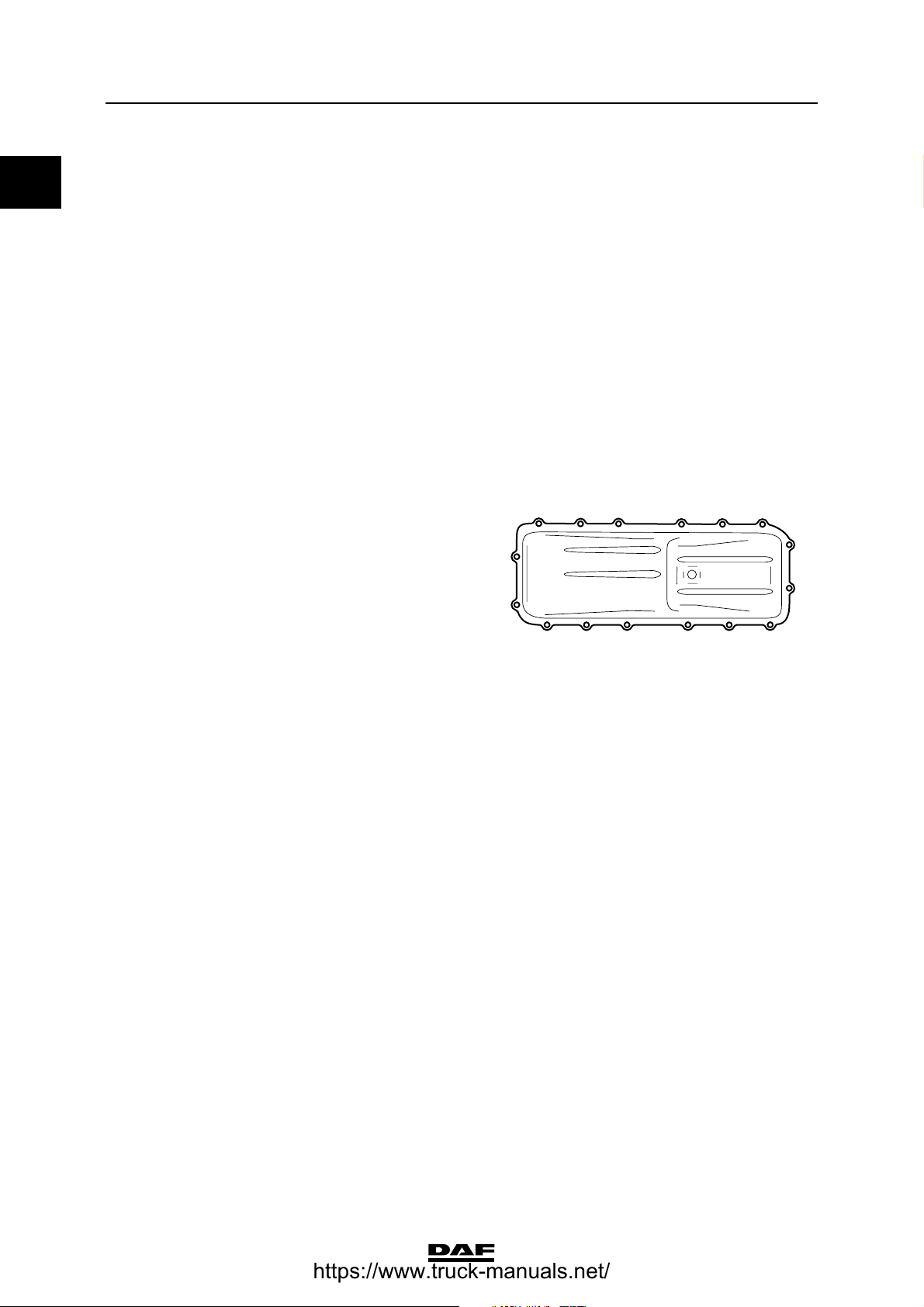
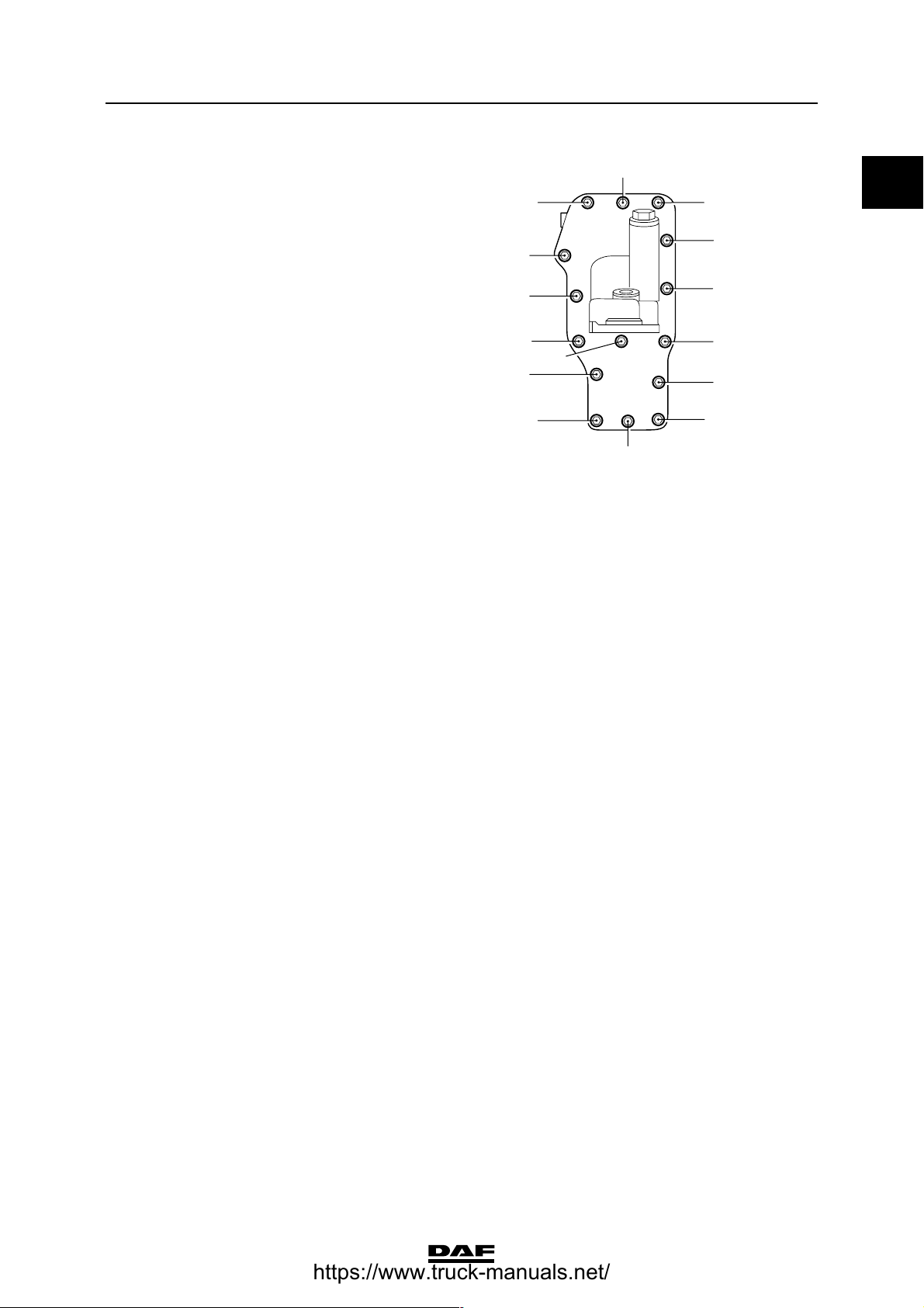
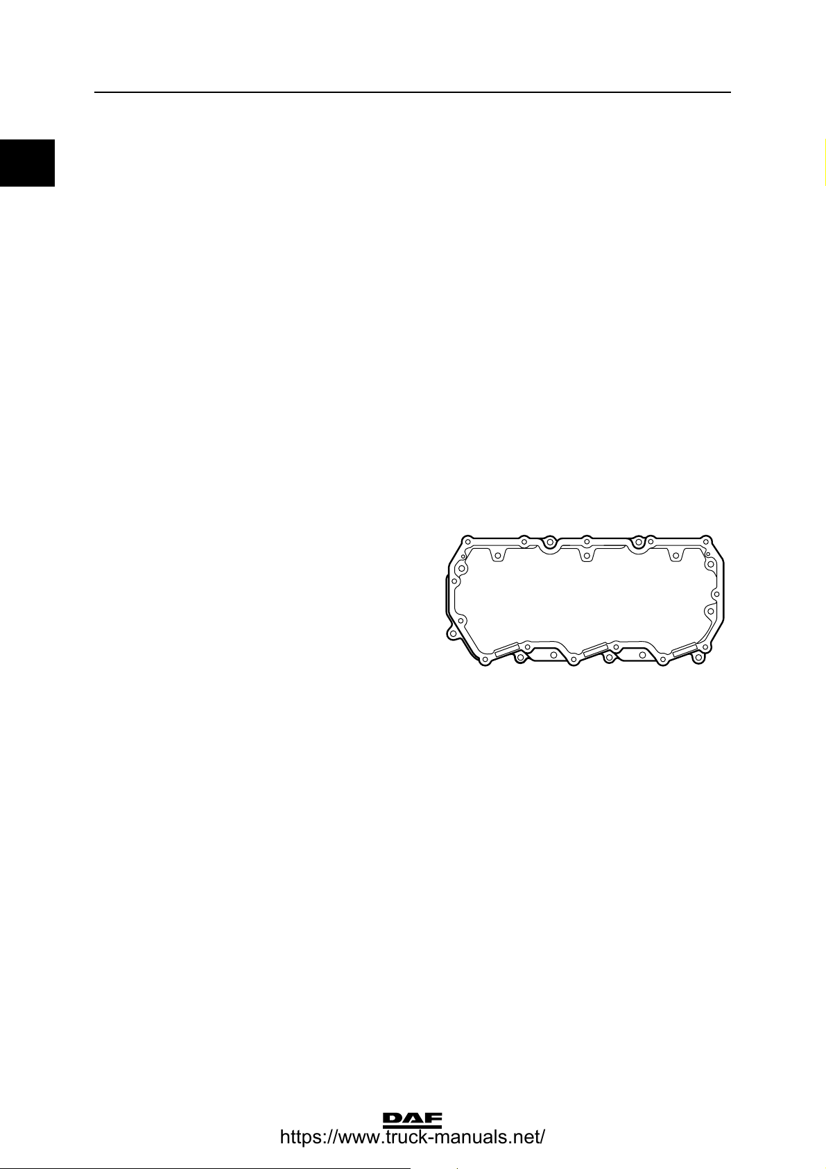
Oil sump
Oil sump attachment
bolts 24 Nm
(1)
16
Oil drain plug 60 Nm
(1) Tighten the attachment bolts in the order indicated
14
ΧΦ65/75/85 series
11 1 3 9
7
5
13
15
Strainer
Suction tube attachment bolts 24 Nm
Bypass pressure regulator
Plug 80 Nm
12 4 2 10
8
6
M201079
3-2
©
200351
Page 19
2
TECHNICAL DATA
ΧΦ65/75/85 series
Oil cooler
Attachment bolts
connecting oil cooler
to cylinder block 24 Nm
(1) Tighten the attachment bolts in the order indicated
Oil pump
Attachment bolts 24 Nm
(1)
13
8
4
7
12
CE-engine lubrication system
14
0
15
9
5
3
2
11
1
6
10
M201145
Turbocharger oil supply pipe
Union on filter head 28 Nm
Union on turbocharger 28 Nm
Bypass pressure regulator
Plug 80 Nm
Oil nozzle
Banjo bolt 15 Nm
Main bearing caps
Main bearing cap attachment bolts
st
phase 60 Nm
1
nd
2
phase 80 Nm
rd
3
phase 90 angular displacement
Big-end bearing caps
Attachment bolts, big-end bearing caps 60 Nm + 60 angular displacement
©
200351 3-3
Page 20

TECHNICAL DATA
2
0
CE-engine lubrication system
3.3 FILLING CAPACITIES
Lubrication system
Total capacity, including oil cooler and oil filter 19.5 litres
Oil sump capacity, maximum level 17.5 litres
Oil sump capacity, minimum level 15.4 litres
ΧΦ65/75/85 series
3-4
©
200351
Page 21

2
TECHNICAL DATA
ΧΦ65/75/85 series
PE engine
4. PE ENGINE
4.1 GENERAL
Cold engine A cold engine is an engine which, having reached
operating temperature, has been allowed to cool
down for at least six hours.
Warm engine A warm engine is an engine which, having
reached operating temperature, has been
allowed to cool down for not more than thirty
minutes.
Direction of rotation of the engine The direction of rotation of the engine is
clockwise, as seen from the timing gear end.
First cylinder of the engine The first cylinder of the engine is the cylinder at
the timing gear end.
Left-hand and right-hand side of the engine The left-hand side of the engine is the side where
the fuel pump is mounted. The right-hand side of
the engine is the side where the air compressor is
mounted.
Engine types
Coding PE 183 C1
PE 228 C
PE 265 C
0
General specifications
Environmental standard Euro 3 (C)
Number of cylinders 6 cylinders in line
Valves 4 per cylinder
Bore x stroke 118 x 140 mm
Total cubic capacity 9,20 l
Compression ratio 17,4 : 1
Fuel injection direct
Injection sequence 1-5-3-6-2-4
Air inlet system Turbocharger intercooling
Cooling fluid
Weight approx. 860 kg
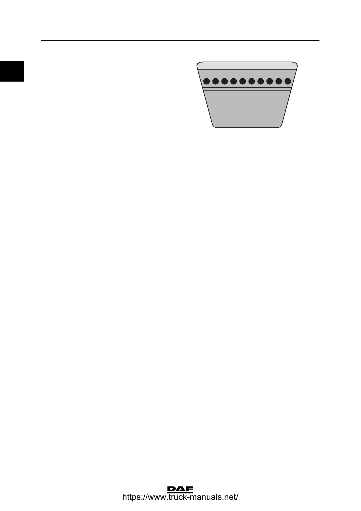
V-belt tension
Belt tension, "AVX" raw edge
Multiple belt Single belt
Setting tension 1200 600
Test tension 800 400
1
of V-belts in Newtons (N)
New V-belt
Run-in V-belt
2
3
Minimum tension 500 250
Correction tension 700 350
©
200351 4-1
Page 22
TECHNICAL DATA
2
0
PE engine
1. Raw-edge V-belts can be recognised by the absence of
textile fabric in the rubber, with the exception of the top
of the belt edge, on the edges and the inside of the belt
(polished belt edge). Version: either a toothed or a nontoothed belt.
2. After fitting the new V-belt, set the pre-tension to the
"setting tension" and after a trial run check whether the
pre-tension complies with the "test tension". If the test
tension reading is lower than the value specified in the
table, set the V-belt to the minimum "test tension".
3. If the V-belt tension is lower than the "minimum tension",
set the belt to the "correction tension".
Cylinder liner
Height above cylinder block 0.02 - 0.10 mm
Cylinder head
Minimum height after overhaul 119.5 mm
Cylinder head test pressure
Test pressure using air (hot) 1.5 bar
ΧΦ65/75/85 series
M2121
Valve clearance
Valve clearance (cold/hot)
inlet 0.45 mm
exhaust 0.45 mm
Valve opening
Valve opening at 1 mm valve clearance 0.45 ≥ 0.2 mm
Axial play
Crankshaft axial play 0.05 - 0.35 mm
Camshaft axial play 0.10 - 0.55 mm
Idler gear axial play 0.03 - 0.25 mm
Gear backlash
Idler gear - crankshaft gear 0.02 - 0.20 mm
Idler gear - fuel pump gear 0.02 - 0.22 mm
Idler gear - camshaft gear 0.02 - 0.22 mm
Camshaft gear - compressor gear 0.02 - 0.22 mm
Fuel pump gear - steering pump gear 0.02 - 0.19 mm
Oil pump idler gear - oil pump gear 0.02 - 0.20 mm
Crankshaft gear - oil pump idler gear 0.02 - 0.20 mm
Number of teeth, timing gears
Crankshaft gear 31
Idler gear 52
Fuel pump gear 62
Camshaft gear 62
Air compressor gear 27
Steering pump gear 18
Oil pump idler gear 28
4-2
©
200351
Page 23

2
TECHNICAL DATA
ΧΦ65/75/85 series
Compression pressure
Differences in compression pressure max. 15%
Flywheel/starter ring gear
Axial variation, measured at a radial distance of
210 mm 0.10 mm
Starter ring gear warm up max. 185C
PE engine
0
©
200351 4-3
Page 24

TECHNICAL DATA
2
0
PE engine
4.2 TIGHTENING TORQUES
Starter motor
Attachment nuts 73 Nm
Alternator
Alternator bracket attachment bolts 30 Nm
Alternator attachment bolts 60 Nm
Pulley attachment nut 80 Nm
Electrical connection to alternator 12 Nm
Air compressor
Compressor gear flange bolt 120 Nm
M12 attachment bolts 110 Nm
M8 attachment bolts for bracket 30 Nm
Cylinder head threaded coupling 90 Nm
Delivery pipe reducer valve 75 Nm
Suction and pressure line unions 90 Nm
Air-conditioning compressor
M12 attachment bolts for compressor bracket 110 Nm
M10 attachment bolts for compressor 60 Nm
ΧΦ65/75/85 series
(1)
(1)
Exhaust manifold
Fit gasket with steel side towards manifold
Sleeved attachment bolts 65 Nm
Heat shield attachment bolts 30 Nm
Inlet manifold
M10 attachment bolts 60 Nm
M10 attachment studs 60 Nm
Turbocharger
Heat shield attachment bolts 30 Nm
Turbine housing clamp plate attachment nut 15 Nm
Attachment nuts
Exhaust manifold flange/turbocharger 60 Nm
Elbow on turbocharger 40 Nm
Oil supply pipe banjo bolt 90 Nm
Fan
Attachment nuts 25 Nm
Fan pulley attachment bolts 30 Nm
(1) Use Loctite 243 to secure
(2) Fasten with Copaslip
(1)
(1)
(2)
(1)
(1)
4-4
©
200351
Page 25

2
TECHNICAL DATA
ΧΦ65/75/85 series
Vibration damper
Vibration damper hub attachment bolts in 4
phases:
st
1
phase, all attachment bolts 50 Nm
2nd phase, all attachment bolts 70 Nm
3rd phase, all attachment bolts 100 Nm
4th phase, all attachment bolts 60 angular displacement
Vibration damper attachment bolts 110 Nm
(1) Tighten the attachment bolts evenly
(2) Use Loctite 243 to secure
(1)
(1)
(1)
(2)
PE engine
0
(1)
©
200351 4-5
Page 26

TECHNICAL DATA
2
0
PE engine
Cylinder head attachment bolts
Cylinder bolts must only be used once. So the
cylinder bolts must always be replaced. The
thread of the new cylinder head bolts is provided
with a red/brown sealant.
Note:
- Due to the sealant used on the cylinder head
bolts, the untightening torque of the cylinder
head bolts can be substantial!
- All M16 and M12 threaded holes must be
carefully cleaned using a screw tap prior to
the mounting of the bolts.
- After tightening of the bolts with the
appropriate tightening torque, the angular
displacement of the M16 bolts must
immediately be started.
- The sealant cannot be applied later.
Tightening cylinder head attachment bolts
Note:
Underneath the bolt head, apply a drop of oil on
the bearing surface of the bolt heads. Sealants
also reduce the frictional resistance, which
means that you must not apply any oil to the
thread.
50 Nm
I
M16
150 Nm
II
ΧΦ65/75/85 series
M16
94 Nm
M12
II
60
III
M16
60
M16
III
M200563
4-6
©
200351
Page 27
2
TECHNICAL DATA
ΧΦ65/75/85 series
1st phase
- M16 in the indicated
order 50 Nm
(1)
2nd phase
- M16 in the indicated
order 150 Nm
- M12 in the indicated
order 94 Nm
(1)
3rd phase
- M16 in the indicated
order in two stages of
(1) Apply a drop of oil to the bearing surface of the M16 and
M12 bolt heads.
60 angular
displacement
Timing gear
Pump housing drive unit attachment bolts 60 Nm
Attachment bolts, pump housing drive shaft
locking plate 30 Nm
Locking plate attachment bolts 30 Nm
Crankshaft hub attachment bolts in 4 phases:
st
1
phase, all attachment bolts 100 Nm
2nd phase, all attachment bolts 100 Nm
3rd phase, all attachment bolts 100 Nm
4th phase, all attachment bolts 100 Nm
Viscous fan clutch attachment nuts 30 Nm
Timing case attachment bolts 30 Nm
Timing cover attachment bolts:
M10 attachment bolts 60 Nm
M8 attachment bolts 25 Nm
Timing cover protection plate attachment bolt 8.5 Nm
Camshaft gear attachment bolt 425 Nm
Idler gear attachment bolt 170 Nm
Pump housing camshaft gear attachment bolt 260 Nm
Steering pump gear attachment nut 80 Nm
Suction pipe banjo bolt 90 Nm
Delivery pipe banjo bolt 40 Nm
16
10
11
(1)
(1)
(1)
(1)
(1)
(2)
(2)
(2)
(2)
(1)
PE engine
8
12
13
M200734
17
0
14
6
1
5
9
4
15
2
7
3
(1) Use Loctite 243 to secure
(2) Apply a drop of oil to the attachment bolts and tighten
evenly.
Flywheel housing
Attachment bolts: 110 Nm
Sealant to be used when fitting flywheel housing Loctite 510
Flywheel
Attachment bolts:
without PTO 170 Nm
(1)
+ 90 angle tightening
with PTO 170 Nm + 150 angle tightening
(1) Use Loctite 243 to secure
©
200351 4-7
Page 28
TECHNICAL DATA
2
0
PE engine
Engine mountings at timing gear end
Cylinder block bracket attachment bolts 92 Nm
Chassis engine bracket attachment bolts 73 Nm
Vibration damper engine bracket attachment
bolts 170 Nm
Engine mountings at flywheel end
Flywheel housing engine bracket attachment
bolts 260 Nm
Chassis engine bracket attachment bolts 73 Nm
Vibration damper engine bracket attachment
bolts 226 Nm + 60 angle tightening
Engine hanger brackets
M12 attachment bolts 110 Nm
Valve gear
Valve cover attachment bolts 25 Nm
M10 setting bolt lock nut for rocker 40 Nm
Bridge piece setting bolt lock nut 40 Nm
Lubricating oil strip/rocker seat attachment bolts 60 Nm
Valve sleeve attachment bolts 30 Nm
Tighten the valve sleeve attachment bolts in the
sequence shown.
13 9
ΧΦ65/75/85 series
3
2117
6
14
5
18
10 12
4
M200959
4-8
©
200351
Page 29
2
TECHNICAL DATA
ΧΦ65/75/85 series
PE-engine cooling system
5. PE-ENGINE COOLING SYSTEM
5.1 GENERAL
Thermostat
Thermostat opening temperature
standard:
- thermostat opens at approx. 87C
- thermostat open at least 12 mm at approx. 99C
with intarder and/or automatic transmission:
- thermostat opens at approx. 83C
- thermostat open at least 12 mm at approx. 95C
Thermostat seat Loctite 638
Coolant pump
Radial play 0.16 - 0.20 mm
Header tank pressure cap
Pressure relief valve opening pressure 1 - 1.2 bar
Underpressure valve opening pressure 0.1 - 0.02 bar
Closed pressure cap position Brand name (2) legible horizontally or 60 before
this position.
0
Closed pressure cap
position
Pressure testing the cooling system
Test pressure 0.7 - 0.9 bar
Viscous fan clutch
Permissible slip at maximum speed control 10%
Brand name (2)
legible horizontally or
60 before this
position.
2
1
M201272
©
200351 5-1
Page 30

TECHNICAL DATA
2
0
PE-engine cooling system
5.2 TIGHTENING TORQUES
The tightening torques recorded in this paragraph
are different from the standard tightening torques
recorded in the overview of the standard
tightening torques. The other threaded
connections which are not recorded must
therefore be tightened to the torque recorded in
the overview of standard tightening torques.
When attachment bolts and nuts are replaced, it
is important - unless stated otherwise - that these
bolts and nuts are of exactly the same length and
property class as those removed.
Coolant pump
M8 attachment bolts 30 Nm
Coolant pipe on cylinder head
Attachment bolts 54 Nm
Coolant pipe threaded coupling 90 Nm
Coolant pipe plug 35 Nm
ΧΦ65/75/85 series
Thermostat housing on coolant pipe
Attachment bolts 30 Nm
Radiator
Attachment nuts 60 Nm
Oil cooler
Coolant drain plug 16 Nm
5-2
©
200351
Page 31

2
TECHNICAL DATA
ΧΦ65/75/85 series
5.3 FILLING CAPACITIES
Cooling system
Cooling system capacity, standard vehicle approx. 38 litres
Cooling system capacity of vehicle with ZF
intarder approx. 50 litres
Cooling system capacity of vehicle with automatic
gearbox approx. 50 litres
PE-engine cooling system
0
©
200351 5-3
Page 32

TECHNICAL DATA
2
0
PE-engine cooling system
ΧΦ65/75/85 series
5-4
©
200351
Page 33

2
TECHNICAL DATA
ΧΦ65/75/85 series
PE-engine lubrication system
6. PE-ENGINE LUBRICATION SYSTEM
6.1 GENERAL
Oil pressure
Oil pressure at engine idling speed 1 bar (warm engine)
Oil pressure at full-load engine speed 3.35 - 4.35 bar
Oil filter
Type filter element
Number 1
Installation in the oil circuit full flow
Opening pressure of bypass valve at a pressure
difference of 2.5 ≥ 0.3 bar
Oil cooler
Coolant test pressure 2.5 bar
Oil consumption
Maximum admissible engine oil consumption 0.3% of the average fuel consumption
Example:
Average measured fuel consumption: 30 litres /
100 km = 300 litres / 1000 km
Maximum admissible engine oil consumption:
0.3% x 300 = 0.9 litres / 1000 km
- Engine oil consumption = 0.9 litres / 1000 km is
permitted
- Engine oil consumption > 0.9 litres / 1000 km;
check the engine using the diagnostics table. See
"Diagnosis".
0
©
200351 6-1
Page 34

TECHNICAL DATA
2
0
PE-engine lubrication system
6.2 TIGHTENING TORQUES
The tightening torques specified in this paragraph
are different from the standard tightening torques
cited in the overview of the standard tightening
torques. The other threaded connections not
specified must therefore be tightened to the
torque cited in the overview of standard
tightening torques.
When attachment bolts and nuts are replaced, it
is important - unless stated otherwise - that these
bolts and nuts are of exactly the same length and
property class as those removed.
Lubricating oil strip/rocker seats
Attachment bolts: 60 Nm
Oil pan
Clamp attachment bolts 25 Nm
Oil drain plug 60 Nm
Oil level sensor 60 Nm
ΧΦ65/75/85 series
Oil pump
Attachment bolts for oil pump housing sections 30 Nm
Attachment bolts connecting oil pump to main
bearing cap 60 Nm
Oil delivery pipe attachment bolts 30 Nm
Idler gear central bolt 60 Nm
Strainer
Bracket attachment bolts 30 Nm
Lubricating oil filter
Lubricating oil filter housing attachment bolts 50 Nm
Filter element screw cap 45 Nm
Bypass pressure regulator
Plug 80 Nm
Oil cooler
Attachment bolts connecting oil cooler to cylinder
block 50 Nm
(1) Use Loctite 243 to secure
(2) Use Loctite 572 to secure
(1)
(1)
(1)
(1)
(2)
Oil nozzles
Banjo bolt (M14) for oil sprayer with locking plate 30 Nm
Banjo bolt (M10) for oil sprayer 30 Nm
6-2
©
200351
Page 35

2
TECHNICAL DATA
ΧΦ65/75/85 series
Main bearing caps
Main bearing cap attachment bolts
1st phase 50 Nm
nd
2
phase 150 Nm
rd
3
phase 120 angular displacement
Big-end bearing caps
Attachment bolts, big-end bearing caps
1st phase, sequence 1-2-3-4 25 Nm
nd
2
phase, sequence 4-3-2-1 35 Nm
rd
3
phase, sequence 1-2-3-4 60 angular displacement
(1) Apply a drop of oil to thread and contact surface.
(2) Connecting rod bolts are to be used once and tightened
as instructed. When fitting the connecting rod in the
engine, apply a drop of oil on the thread and bearing face
of the connecting rod bolts.
(1)
(2)
PE-engine lubrication system
1 4
0
32
M200661
©
200351 6-3
Page 36

TECHNICAL DATA
2
0
PE-engine lubrication system
6.3 FILLING CAPACITIES
Lubrication system
Total capacity, including oil cooler and oil filter approx. 29 litres
Oil sump capacity, maximum level approx. 24 litres
Oil pan capacity, minimum level approx. 16 litres
ΧΦ65/75/85 series
6-4
©
200351
Page 37

2
TECHNICAL DATA
ΧΦ65/75/85 series
XE engine
7. XE ENGINE
7.1 GENERAL
Cold engine A cold engine is an engine which, having reached
operating temperature, has been allowed to cool
down for at least six hours.
Warm engine A warm engine is an engine which, having
reached operating temperature, has been
allowed to cool down for not more than thirty
minutes.
Direction of rotation of the engine The direction of rotation of the engine is
clockwise, as seen from the timing gear end.
First cylinder of the engine The first cylinder of the engine is the cylinder at
the timing gear end.
Left-hand and right-hand side of the engine The left-hand side of the engine is the side where
the fuel pump is mounted. The right-hand side of
the engine is the side where the air compressor is
mounted.
Engine types
Coding XE 250 C 1
XE 280 C 1
XE 280 C 3
XE 315 C 1
XE 315 C 3
XE 355 C 1
0
General specifications
Environmental standard Euro 3 (C)
Number of cylinders 6
Valves 4 per cylinder
Bore x stroke 130 x 158 mm
Total cubic capacity 12.6 l
Compression ratio 17,4 : 1
Fuel injection direct
Injection sequence 1-5-3-6-2-4
Air inlet system Turbocharger intercooling
Cooling fluid
Weight approx. 1,080 kg
©
200351 7-1
Page 38

TECHNICAL DATA
2
0
XE engine
V-belt tension
V-belt tension, "AVX" raw edge
Application example: air-conditioning compressor drive
New V-belt
(2)
Setting tension 600
Test tension ¥ 400
Run-in V-belt
(3)
Minimum tension 250
Correction tension 350
V-belt tension, "XPB" raw edge
Application example: steering pump drive on FAX vehicle
New V-belt
(2)
Setting tension 1250
Test tension ¥ 950
Run-in V-belt
(3)
(1)
(1)
(N)
(N)
ΧΦ65/75/85 series
Minimum tension 750
Correction tension 950
(1) Raw-edge V-belts can be recognised by the absence of
textile fabric in the rubber, with the exception of the top of
the belt edge, on the edges and the inside of the belt
(polished belt edge). Version: either a toothed or a nontoothed belt.
(2) After fitting the new V-belt, set the pre-tension to the
"setting tension" and after a trial run inspect whether the
pre-tension complies with the "test tension". If the test
tension reading is lower than the value specified in the
table, set the V-belt to the minimum "test tension".
(3) If the V-belt tension is lower than the "minimum tension",
set the belt to the "adjusting tension".
M2121
7-2
©
200351
Page 39

2
TECHNICAL DATA
ΧΦ65/75/85 series
Automatic poly-V-belt tensioner
Torsional moment
from rest position (0)
to 17 mm torsion (A) 19 - 37 Nm
XE engine
0
0
A
Cylinder liner
Height above cylinder block 0.02 - 0.10 mm
Cylinder head
Minimum height after overhaul 119.50 mm
Test pressure using air (hot) 1.5 bar
Valve clearance
Valve clearance (cold/hot)
inlet 0.50 mm
exhaust 0.50 mm
Axial play
Crankshaft axial play 0.06 - 0.32 mm
Camshaft axial play 0.10 - 0.55 mm
Idler gear axial play 0.05 - 0.25 mm
M201274
©
200351 7-3
Page 40

TECHNICAL DATA
2
0
XE engine
Gear backlash
Idler gear - crankshaft gear 0.02 - 0.21 mm
Idler gear - pump housing camshaft gear 0.02 - 0.22 mm
Idler gear - camshaft gear 0.02 - 0.21 mm
Camshaft gear - compressor gear 0.02 - 0.22 mm
Pump housing camshaft gear - steering pump
gear 0.02 - 0.19 mm
Oil pump idler gear - oil pump gear 0.02 - 0.20 mm
Crankshaft gear - oil pump idler gear 0.02 - 0.20 mm
Number of teeth, timing gears
Crankshaft gear 35
Idler gear 54
Pump housing - camshaft gear wheel 70
Camshaft gear 70
Air compressor gear 27
Fan drive housing gear 29
Steering pump gear 18
Lubricating oil pump idler gear 34
Compression pressure
Differences in compression pressure max. 15%
ΧΦ65/75/85 series
Flywheel/starter ring gear
Axial variation, measured at a radial distance of
210 mm 0.10 mm
Starter ring gear warm up max. 185|C
7-4
©
200351
Page 41

2
TECHNICAL DATA
ΧΦ65/75/85 series
7.2 TIGHTENING TORQUES
The tightening torques specified in this paragraph
are different from the standard tightening torques
cited in the overview of the standard tightening
torques. The other threaded connections not
specified must therefore be tightened to the
torque cited in the overview of standard
tightening torques.
When attachment bolts and nuts are replaced, it
is important - unless stated otherwise - that these
bolts and nuts are of exactly the same length and
property class as those removed.
Starter motor
Attachment nuts 73 Nm
Electrical connection to starter motor 28 Nm
Alternator
Alternator attachment bolts 60 Nm
Pulley attachment nut 80 Nm
Electrical connection to alternator (M8) 15 Nm
XE engine
0
(1)
Air compressor
M12 attachment bolts 110 Nm
M8 attachment bolts for bracket 30 Nm
M10 attachment bolts for bracket 60 Nm
Compressor gear flange bolt 120 Nm
M14 threaded coupling for cylinder head 40 Nm
M26 threaded coupling for cylinder head 90 Nm
Cylinder head service line banjo bolt 25 Nm
Pressure line safety valve 75 Nm
Suction and pressure line unions 90 Nm
Oil supply banjo bolt 25 Nm
Exhaust manifold
Fit gasket with steel side towards manifold
Sleeved attachment bolts 65 Nm
Heat shield attachment bolts 30 Nm
Inlet manifold
Attachment bolts: 46 Nm
Air inlet hose clamps 12 Nm
Electrical connection to glow plug 8.5 Nm
Attachment bolts, boost pressure/charge
temperature sensor 4 Nm
Hose clamps 12 Nm
(1)
©
200351 7-5
Page 42

TECHNICAL DATA
2
0
XE engine
Turbocharger
Heat shield attachment bolts 30 Nm
Turbine housing clamp plate attachment nut 15 Nm
Attachment nuts
Exhaust manifold flange/turbocharger 60 Nm
Elbow on turbocharger 40 Nm
Oil supply pipe banjo bolt 90 Nm
(1) Use Loctite 243 to secure
(2) Fasten with Copaslip
Glow plug relay
Glow plug relay cap 2 Nm
Electrical connections to glow plug relay:
M5 3.5 Nm
M8 8 Nm
Main fuse
Fuse holder (M6) 4.5 Nm
Fuse (M8) 18 Nm
ΧΦ65/75/85 series
(1)
(2)
Vibration damper and fan drive
Vibration damper
hub attachment bolts
(1) in 4 phases:
st
1
phase, all
attachment bolts 100 Nm
2nd phase, all
attachment bolts 100 Nm
3rd phase, all
attachment bolts 100 Nm
4th phase, all
attachment bolts 100 Nm
Attachment bolts,
vibration damper (5) 110 Nm
Attachment nuts, fan
drive (8) 60 Nm
Attachment bolts, fan
pulley (9) 30 Nm
Attachment nuts, fan
clutch (7) 25 Nm
(1) Tighten the attachment bolts evenly
(2) Use Loctite 243 to secure
(2)
(2)
(1)
(1)
(1)
(1)
(2)
10
8
9
7
6
5
4
3
2
1
M201153
7-6
©
200351
Page 43

2
TECHNICAL DATA
ΧΦ65/75/85 series
Cylinder head attachment bolts
Cylinder head bolts must only be used once. So
the cylinder head bolts must always be replaced.
The thread of the new cylinder head bolts is
provided with a red/brown sealant.
Note:
- Due to the sealant used on the cylinder head
bolts, the untightening torque of the cylinder
head bolts can be substantial!
- All M16 and M12 threaded holes must be
carefully cleaned using a screw tap prior to
the mounting of the bolts.
- After tightening of the bolts with the
appropriate tightening torque, the angular
displacement of the M16 bolts must
immediately be started.
- The sealant cannot be applied later.
50 Nm
I
M16
150 Nm
II
M16
XE engine
0
94 Nm
M12
60
III
II
60
M16
M16
III
M200563
©
200351 7-7
Page 44

TECHNICAL DATA
2
0
XE engine
Tightening cylinder head attachment bolts
Note:
Underneath the bolt head, apply a drop of oil on
the bearing surface of the bolt heads. Sealants
also reduce the frictional resistance, which
means that you must not apply any oil to the
thread.
1st phase
- M16 in the indicated
order 50 Nm
2nd phase
- M16 in the indicated
order 150 Nm
- M12 in the indicated
order 94 Nm
3rd phase
- M16 in the indicated
order in two stages of
(1) Apply a drop of oil to the bearing surface of the M16 and
M12 bolt heads.
60 angular
displacement
(1)
(1)
16
15
21
17
10
18 19
11
6
5
ΧΦ65/75/85 series
17
4
8
2
3
9
20
12
13
14
M200562
Timing gear
Pump housing drive unit attachment bolts 60 Nm
Attachment bolts, pump housing drive shaft
locking plate 30 Nm
Locking plate attachment bolts 30 Nm
Crankshaft hub attachment bolts in 4 phases:
st
1
phase, all attachment bolts 100 Nm
2nd phase, all attachment bolts 100 Nm
3rd phase, all attachment bolts 100 Nm
4th phase, all attachment bolts 100 Nm
Viscous fan clutch attachment nuts 30 Nm
Timing case attachment bolts 30 Nm
Timing cover attachment bolts:
- M10 attachment bolts 60 Nm
- M8 attachment bolts 25 Nm
Timing cover protection plate attachment bolt 8.5 Nm
Camshaft gear attachment bolt 425 Nm
Idler gear attachment bolt 170 Nm
Pump housing camshaft gear attachment bolt 260 Nm
Steering pump gear attachment nut 80 Nm
Suction pipe banjo bolt 90 Nm
Delivery pipe banjo bolt 40 Nm
(1) Use Loctite 243 to secure
(2) Apply a drop of oil to the attachment bolts and tighten
evenly.
(1)
(1)
(2)
(2)
(2)
(2)
(1)
(1)
(1)
(1)
7-8
©
200351
Page 45

2
TECHNICAL DATA
ΧΦ65/75/85 series
Flywheel housing
Attachment bolts 110 Nm
Sealant to be used when fitting flywheel housing Loctite 510
Attachment bolt, crankshaft sensor 8 Nm
(1) Use Loctite 243 to secure
Flywheel
Attachment bolts:
- standard 260 Nm + 60 angle tightening
- with engine PTO 260 Nm + 120 angle tightening
Engine mountings at timing gear end
Cylinder block bracket attachment bolts 110 Nm
Chassis engine bracket attachment bolts 110 Nm
Vibration damper engine bracket attachment
bolts 170 Nm
Engine mountings at flywheel end
Flywheel housing engine bracket attachment
bolts 260 Nm
Chassis engine bracket attachment bolts 110 Nm
Vibration damper engine bracket attachment
bolts 260 Nm + 90 angle tightening
(1)
XE engine
0
Engine hanger brackets
Attachment bolts: 110 Nm
Valve gear
Valve cover attachment bolts 25 Nm
Rocker setting bolt lock nut 40 Nm
Bridge piece setting bolt lock nut 40 Nm
Lubricating oil strip/rocker seat attachment bolts 110 Nm
DEB set screw nut 25 Nm
Solenoid valve 20 Nm
Wiring harness attachment bolt 9 Nm
Valve sleeve attachment bolts 30 Nm
Tighten the valve sleeve attachment bolts in the
sequence shown
3
5
1
11
13
9157
2
6
814
41210
M200942
©
200351 7-9
Page 46

TECHNICAL DATA
2
0
XE engine
ΧΦ65/75/85 series
7-10
©
200351
Page 47

2
TECHNICAL DATA
ΧΦ65/75/85 series
XE-engine cooling system
8. XE-ENGINE COOLING SYSTEM
8.1 GENERAL
Thermostat
Thermostat opening temperatures:
standard
- thermostat opens at approx. 87C
- thermostat open at least 12 mm at approx. 99C
with intarder and/or tropical cooling:
- thermostat opens at approx. 83C
- thermostat open at least 12 mm at approx. 95C
Thermostat seat Loctite 638
Coolant pump
Maximum radial play 0.16 - 0.20 mm
Header tank pressure cap
Pressure relief valve opening pressure 1 - 1.2 bar
Underpressure valve opening pressure 0.1 - 0.02 bar
Closed pressure cap position Brand name (2) legible horizontally or 60 before
this position.
0
Closed pressure cap
position
Pressure testing the cooling system
Test pressure 0.7 - 0.9 bar
Viscous fan clutch
Permissible slip at maximum speed control 10%
Fan drive ( i ) transmission 1,207
Brand name (2)
legible horizontally or
60 before this
position.
2
1
M201272
©
200351 8-1
Page 48

TECHNICAL DATA
2
0
XE-engine cooling system
8.2 TIGHTENING TORQUES
The tightening torques specified in this paragraph
are different from the standard tightening torques
cited in the overview of the standard tightening
torques. The other threaded connections not
specified must therefore be tightened to the
torque cited in the overview of standard
tightening torques.
When attachment bolts and nuts are replaced, it
is important - unless stated otherwise - that these
bolts and nuts are of exactly the same length and
property class as those removed.
Coolant pump
M8 attachment bolts 30 Nm
M14 threaded coupling 35 Nm
M26 90 Nm
Coolant pipe
Attachment bolts 60 Nm
Coolant pipe threaded coupling 90 Nm
Coolant pipe plug 35 Nm
Engine coolant temperature sensor 20 Nm
ΧΦ65/75/85 series
Thermostat housing
Attachment bolts 30 Nm
Plug 35 Nm
Radiator
Attachment nuts 70 Nm
Coolant hoses
Hose clamps 7 Nm
8-2
©
200351
Page 49

2
TECHNICAL DATA
ΧΦ65/75/85 series
8.3 FILLING CAPACITIES
Cooling system capacity approx. 47 litres
Cooling system capacity of vehicle with ZF
intarder approx. 57 litres
XE-engine cooling system
0
©
200351 8-3
Page 50

TECHNICAL DATA
2
0
XE-engine cooling system
ΧΦ65/75/85 series
8-4
©
200351
Page 51

2
TECHNICAL DATA
ΧΦ65/75/85 series
XE-engine lubrication system
9. XE-ENGINE LUBRICATION SYSTEM
9.1 GENERAL
Oil pressure
Oil pressure at engine idling speed 1 bar (warm engine)
Oil pressure at full-load engine speed 3.5 - 4.5 bar
Oil filter
Type filter element
Number 1
Installation in the oil circuit full flow
Opening pressure of bypass valve at a pressure
difference of 2.5 ≥ 0.3 bar
Oil cooler
Coolant test pressure maximum 2.5 bar
Oil consumption
Maximum admissible engine oil consumption 0.3% of the average fuel consumption
0
Example:
Average measured fuel consumption: 30 litres /
100 km = 300 litres / 1000 km
Maximum admissible engine oil consumption:
0.3% x 300 = 0.9 litres / 1000 km
- Engine oil consumption = 0.9 litres / 1000 km is
permitted
- Engine oil consumption > 0.9 litres / 1000 km;
check the engine using the diagnostics table. See
"Diagnosis".
©
200351 9-1
Page 52

TECHNICAL DATA
2
0
XE-engine lubrication system
9.2 TIGHTENING TORQUES
The tightening torques specified in this paragraph
are different from the standard tightening torques
cited in the overview of the standard tightening
torques. The other threaded connections not
specified must therefore be tightened to the
torque cited in the overview of standard
tightening torques.
When attachment bolts and nuts are replaced, it
is important - unless stated otherwise - that these
bolts and nuts are of exactly the same length and
property class as those removed.
Lubricating oil strip/rocker seats
Attachment bolts 110 Nm
Oil pan
Clamp attachment bolts 25 Nm
Oil drain plug 60 Nm
Oil level sensor 60 Nm
ΧΦ65/75/85 series
Oil pump
Attachment bolts for oil pump housing sections 30 Nm
Attachment bolts connecting oil pump to main
bearing cap 60 Nm
Oil delivery pipe attachment bolts 30 Nm
Idler gear central bolt 60 Nm
Strainer
Bracket attachment bolts 30 Nm
Lubricating oil filter
Lubricating oil filter housing attachment bolts 50 Nm
Filter element screw cap 40 Nm
(1) Use Loctite 243 to secure
(2) Use Loctite 572 to secure
Bypass pressure regulator
Plug 80 Nm
Oil cooler
Attachment bolts connecting oil cooler to cylinder
block 50 Nm
Coolant supply pipe union 90 Nm
Plug, adjustable banjo connection 90 Nm
Banjo bolt, adjustable banjo connection 90 Nm
(1)
(1)
(1)
(1)
(2)
Centrifugal oil filter
Central bolt 20 Nm
9-2
©
200351
Page 53

2
TECHNICAL DATA
ΧΦ65/75/85 series
Oil nozzle
Oil nozzle banjo bolt 30 Nm
Main bearing caps
Main bearing cap attachment bolts
Big-end bearing caps
Attachment bolts (1),
cracked big-end
bearing caps
1st phase 100 Nm
nd
2
phase 175 Nm ≥ 15 Nm
rd
3
phase 60 angular
(2)
displacement
(1)
150 Nm + 120 angle tightening
1
2
XE-engine lubrication system
0
5
4
3
Attachment bolts,
big-end bearing
(2)
caps
1st phase, sequence
1-2-3-4 35 Nm
nd
2
phase, sequence
4-3-2-1 45 Nm
rd
3
phase, sequence
1-2-3-4
(1) Apply a drop of oil to thread and contact surface.
(2) Connecting rod bolts are to be used once and tightened
as instructed. When fitting the connecting rod in the
engine, apply a drop of oil to the threads and contact
surfaces of the connecting rod bolts.
60 angular
displacement
1
M2 01 285
1 4
32
M200661
©
200351 9-3
Page 54

TECHNICAL DATA
2
0
XE-engine lubrication system
9.3 FILLING CAPACITIES
Lubrication system
Total capacity, including oil cooler and oil filter approx. 35 litres
Oil sump capacity, maximum level approx. 30 litres
Oil pan capacity, minimum level approx. 22 litres
ΧΦ65/75/85 series
9-4
©
200351
Page 55

2
DIAGNOSTICS
ΧΦ65/75/85 series
1 Diagnostics
CONTENTS
Page Date
1. TRACTIVE PROBLEMS . . . . . . . . . . . . . . . . . . . . . . . . . . . . . . . . . . . . . . . . . . . 1-1 . . . . . 200351
1.1 Introduction . . . . . . . . . . . . . . . . . . . . . . . . . . . . . . . . . . . . . . . . . . . . . . . . 1-1 . . . . . 200351
1.2 Acceleration test . . . . . . . . . . . . . . . . . . . . . . . . . . . . . . . . . . . . . . . . . . . . 1-2 . . . . . 200351
1.3 Acceleration test form . . . . . . . . . . . . . . . . . . . . . . . . . . . . . . . . . . . . . . . . 1-4 . . . . . 200351
1.4 Acceleration test using DAVIE-XD . . . . . . . . . . . . . . . . . . . . . . . . . . . . . . 1-5 . . . . . 200351
2. CE ENGINE, GENERAL . . . . . . . . . . . . . . . . . . . . . . . . . . . . . . . . . . . . . . . . . . . 2-1 . . . . . 200351
2.1 Introduction . . . . . . . . . . . . . . . . . . . . . . . . . . . . . . . . . . . . . . . . . . . . . . . . 2-1 . . . . . 200351
2.2 Fault-finding table, engine functions . . . . . . . . . . . . . . . . . . . . . . . . . . . . . 2-2 . . . . . 200351
2.3 Fault-finding table, vehicle functions . . . . . . . . . . . . . . . . . . . . . . . . . . . . . 2-6 . . . . . 200351
3. CE-ENGINE COOLING SYSTEM . . . . . . . . . . . . . . . . . . . . . . . . . . . . . . . . . . . . 3-1 . . . . . 200351
3.1 Introduction . . . . . . . . . . . . . . . . . . . . . . . . . . . . . . . . . . . . . . . . . . . . . . . . 3-1 . . . . . 200351
3.2 Fault-finding table . . . . . . . . . . . . . . . . . . . . . . . . . . . . . . . . . . . . . . . . . . . 3-2 . . . . . 200351
4. CE-ENGINE LUBRICATION SYSTEM . . . . . . . . . . . . . . . . . . . . . . . . . . . . . . . . 4-1 . . . . . 200351
4.1 Introduction . . . . . . . . . . . . . . . . . . . . . . . . . . . . . . . . . . . . . . . . . . . . . . . . 4-1 . . . . . 200351
4.2 Fault-finding table . . . . . . . . . . . . . . . . . . . . . . . . . . . . . . . . . . . . . . . . . . . 4-2 . . . . . 200351
5. PE/XE ENGINE, GENERAL . . . . . . . . . . . . . . . . . . . . . . . . . . . . . . . . . . . . . . . . 5-1 . . . . . 200351
5.1 Introduction . . . . . . . . . . . . . . . . . . . . . . . . . . . . . . . . . . . . . . . . . . . . . . . . 5-1 . . . . . 200351
5.2 Fault-finding table, engine functions . . . . . . . . . . . . . . . . . . . . . . . . . . . . . 5-2 . . . . . 200351
5.3 Fault-finding table, vehicle functions . . . . . . . . . . . . . . . . . . . . . . . . . . . . . 5-6 . . . . . 200351
Contents
1
6. PE/XE-ENGINE COOLING SYSTEM . . . . . . . . . . . . . . . . . . . . . . . . . . . . . . . . . 6-1 . . . . . 200351
6.1 Introduction . . . . . . . . . . . . . . . . . . . . . . . . . . . . . . . . . . . . . . . . . . . . . . . . 6-1 . . . . . 200351
6.2 Fault-finding table . . . . . . . . . . . . . . . . . . . . . . . . . . . . . . . . . . . . . . . . . . . 6-2 . . . . . 200351
7. XE/PE-ENGINE LUBRICATION SYSTEM . . . . . . . . . . . . . . . . . . . . . . . . . . . . . 7-1 . . . . . 200351
7.1 Introduction . . . . . . . . . . . . . . . . . . . . . . . . . . . . . . . . . . . . . . . . . . . . . . . . 7-1 . . . . . 200351
7.2 Fault-finding table . . . . . . . . . . . . . . . . . . . . . . . . . . . . . . . . . . . . . . . . . . . 7-2 . . . . . 200351
©
200351 1
Page 56

DIAGNOSTICS
2
1
Contents
ΧΦ65/75/85 series
2
©
200351
Page 57

2
DIAGNOSTICS
ΧΦ65/75/85 series
1. TRACTIVE PROBLEMS
1.1 INTRODUCTION
There may be many reasons why a vehicle's
performance is below standard.
Some of these may be mechanical, but some
may be psychological in nature.
It is therefore important to identify the problem
properly.
Try to get as much information as possible from
the customer or driver.
- When does the vehicle not perform properly?
- What are the road or weather conditions
when this occurs?
- What are the vehicle's loading conditions?
- Is the vehicle not being compared with a
vehicle with completely different
specifications, for instance engine power?
- Is the vehicle being driven in the correct
engine speed range?
Tractive problems
1
If the answers are unsatisfactory, ask the
customer or driver for facts.
- Tachograph cards of trips
- Reliable consumption figures of trips
Following correct identification of the complaint,
vehicle performance can be tested by an
acceleration test.
If the vehicle fails to pass the acceleration test, a
boost pressure curve may be plotted as an aid to
identifying the cause.
Note:
Checking the boost pressure will in general only
make sense after the vehicle has covered at least
20,000 km.
©
200351 1-1
Page 58

DIAGNOSTICS
2
1
Tractive problems
1.2 ACCELERATION TEST
1. Use the "Acceleration test form", which is
included in the Workshop Manual.
2. Do the checks set out under "Before starting
the acceleration test".
3. Establish a test route where the difference
between the measured times in both
directions does not exceed 15%. If the
difference in time exceeds 15%, find another
test route.
4. Establish the starting and end points on the
selected test route, to ensure that exactly the
same route can be taken in both directions.
Do the entire test at least twice and take the
average time.
5. Run the drive train at operating temperature
(drive for at least 15 minutes with a loaded
vehicle).
ΧΦ65/75/85 series
Note:
When switched on, the air compressor and
fan consume 10 to 15 kW engine power on
average. During the test try to avoid these
two consumers being switched on.
6. Connect DAVIE and follow the instructions
given.
7. Fully depress the accelerator pedal during
the acceleration test.
1-2
©
200351
Page 59

2
DIAGNOSTICS
ΧΦ65/75/85 series
Result of first acceleration test
If the acceleration time is not achieved, first carry
out the following work.
- Check the fuel system for the presence of air.
- Replace or clean the air filter element.
- Check the setting of the wastegate on the
turbocharger (if present).
- Check the exhaust brake butterfly valve for
correct operation.
- Check the charge cooler exterior for dirt
deposits.
- Clean the water separator (if present).
- Check that the primer pump is attached.
- Replace the fuel fine filter.
- Check the suction pipe of the tank for
clogging by coarse dirt.
- Check the fuel tank for fouling. Clean with a
steam cleaner, if necessary.
- Check the air intake system for any leaks.
- Check the exhaust system for any leaks.
- Check the exhaust system for blockages by
measuring the exhaust back pressure.
- Check the turbocharger impellers on the
compressor and turbine sides for damage
and for deposits of salt or any other
contaminants.
- Check both the valve clearance and the DEB
clearance (if present).
- Check the injector pipes for damage.
- Check the fuel gallery/rail pressure.
- Check the fuel lift pump output.
- Check whether the right type of components
has been fitted. This includes turbocharger,
injectors, etc.
- Check the opening pressure of the injectors
(if possible).
Tractive problems
1
Repeat the acceleration test. If necessary, plot a
boost pressure curve.
©
200351 1-3
Page 60

DIAGNOSTICS
2
1
Tractive problems
ΧΦ65/75/85 series
1.3 ACCELERATION TEST FORM
General data
Customer's name:__________________________________________
Chassis number:______________ Registration number:______
Test conditions
Weather conditions: dry / rain / wet road / drizzle
Wind force: none / average / strong Outside temperature:_______
Vehicle data
Vehicle type:________ Trailer type:_________ Superstructure:____________
Total combination weight: ________kg Total vehicle height: _________m
Cab type: day / sleeper / space / superspace
Aerodynamics: roof spoiler / fenders / front spoiler / skirts / sun visor / ____________________
Engine type:________ Gearbox type:_____________ Transmission:_________
|
C
Rear axle type:_______________ Transmission:_______________
Tyre size: front:__________ rear:____________________
Tyre make:_______________ Energy:____________________
Space between cab and superstructure/trailer: _________________m
TOPEC data
Starting speed: ___________km/h End speed: _____________km/h
Gear selection:___________ Acceleration time: __________sec.
Measured time of outward
journey:
Measured time of return
journey:
1: _______sec.
2: _______sec. Average time of outward journey: ________sec.
3: _______sec.
Average time: _________sec.
1: _______sec.
2: _______sec. Average return time: _________sec.
3: _______sec.
1-4
©
200351
Page 61

2
DIAGNOSTICS
ΧΦ65/75/85 series
1.4 ACCELERATION TEST USING DAVIE-XD
The acceleration test can also be carried out
using DAVIE-XD. Collect the necessary data and,
after starting DAVIE-XD, go to the engine
management system and carefully follow the
instructions in DAVIE-XD for carrying out the test
correctly.
The test results should be saved to diskette after
each test.
The acceleration test in DAVIE-XD
should only be started when the
}
When driving, never start a "direct test" or "guide
diagnosis".
vehicle is stationary. As the
communication between the
accelerator pedal sensor and the
unit will be broken for a short time
when DAVIE is started up, this can
lead to dangerous situations when
the vehicle is being driven.
Tractive problems
1
©
200351 1-5
Page 62

DIAGNOSTICS
2
1
Tractive problems
ΧΦ65/75/85 series
1-6
©
200351
Page 63

2
DIAGNOSTICS
ΧΦ65/75/85 series
2. CE ENGINE, GENERAL
2.1 INTRODUCTION
If there is a fault in the system, it is usually
detected by the electronic unit in the form of a
fault code. This fault code can be read out using
DAVIE. The fault-finding table contains possible
causes of symptoms not detected by the
electronic unit.
CE engine, general
1
©
200351 2-1
Page 64

DIAGNOSTICS
2
1
CE engine, general
ΧΦ65/75/85 series
2.2 FAULT-FINDING TABLE, ENGINE FUNCTIONS
SYMPTOM: ENGINE CAN BE STARTED, BUT DOES NOT RUN
Possible cause Remedy
Poor fuel quality Drain fuel, flush fuel system, replace the fuel filters
and fill fuel tank with fuel
Air in fuel system Check for drawing in of air:
- via the suction pipe
- via the fuel lift pump seal
Fuel filter clogged Replace the fuel filter and clean the system
While carrying out an engine test with DAVIE,
communication with DAVIE was interrupted
No fuel supply/fuel lift pump defective; no delivery Check:
SYMPTOM: ENGINE STALLS AND RUNS AGAIN AFTER RE-STARTING
Remove the battery earth lead and then refit it
- the fuel level
- the pipes for blockage and leaks
- the fuel lift pump
Possible cause Remedy
Air in fuel system Check for drawing in of air:
- via the suction pipe
- via the fuel lift pump seal
SYMPTOM: ENGINE STARTS POORLY
Possible cause Remedy
Poor fuel quality Drain fuel, flush fuel system, replace the fuel filters
and fill fuel tank with fuel
Air in fuel system Check for drawing in of air:
- via the suction pipe
- via the fuel lift pump seal
Fuel filter clogged Replace the fuel filter and clean the system
Battery voltage too low Charge the batteries
Mechanical defect or clogging in injector Replace the injector
Fuel lift pump delivery too low Check the fuel lift pump and replace if necessary
Internal leakage between the fuel supply pipe and
the injector
Check the fuel supply pipe/injector connections for
internal leaks.
2-2
©
200351
Page 65

2
DIAGNOSTICS
ΧΦ65/75/85 series
SYMPTOM: ENGINE RUNS AT (INCREASED) IDLING SPEED AND DOES NOT RESPOND TO
ACCELERATOR PEDAL
Possible cause Remedy
Mechanical defect of accelerator pedal sensor Check:
- the mechanical connection between the
sensor and the accelerator pedal
- the accelerator pedal sensor
Fuel quantity adjustment by ABS/ASR
Engine brake input signal present Check the electrical system of the engine brake
SYMPTOM: DIESEL KNOCK DURING ACCELERATION
Possible cause Remedy
Poor fuel quality Drain fuel, flush fuel system, replace the fuel filters
and fill fuel tank with fuel
Air in fuel system Check for drawing in of air:
- via the suction pipe
- via the fuel lift pump seal
CE engine, general
1
Fault in electrical components/wiring of the engine
coolant temperature sensor
Injector defective Check the injectors.
Crankshaft position sensor defective Check the crankshaft position sensor
SYMPTOM: IRREGULAR RUNNING OF ENGINE
Possible cause Remedy
Poor fuel quality Drain fuel, flush fuel system, replace the fuel filters
Air in fuel system Check for drawing in of air:
Fuel filter clogged Replace the fuel filter
Connection points on injectors mixed up Connect the correct connection points to the
Mechanical defect or clogging in injectors Replace the injectors
Injector defective Check the injectors.
Fuel lift pump delivery too low Check the fuel lift pump and replace if necessary
Pressure relief valve on common rail does not shut
off
Check the electrical system
and fill fuel tank with fuel
- via the suction pipe
- via the fuel lift pump seal
correct injector
Check the pressure relief valve
©
200351 2-3
Page 66

DIAGNOSTICS
2
1
CE engine, general
SYMPTOM: REDUCED POWER AT ALL ENGINE SPEEDS
Possible cause Remedy
Poor fuel quality Drain fuel, flush fuel system, replace the fuel filters
and fill fuel tank with fuel
Fuel filter clogged Replace the fuel filter
Mechanical defect of accelerator pedal sensor Check:
- the mechanical connection between the
sensor and the accelerator pedal
- the accelerator pedal sensor
Fault in electrical components/wiring of:
- contacts
- contact resistors in connector connections
Air filter clogged. Replace or clean the air filter.
Turbocharger defective/wastegate control
incorrect.
Air leak in inlet system. Pressure-test the inlet system.
Mechanical defect or clogging in injectors Replace the injectors
Check the electrical system
Check the turbocharger/wastegate control.
ΧΦ65/75/85 series
Injector defective Check the injectors.
Pressure relief valve on pump housing does not
shut off
Fuel lift pump delivery too low Check the fuel lift pump and replace if necessary
SYMPTOM: REDUCED POWER ABOVE A CERTAIN ENGINE SPEED
Possible cause Remedy
Fuel filter partially clogged Replace the fuel filter
Air filter partially clogged. Replace or clean the air filter.
Air leak in inlet system. Pressure-test the inlet system.
Pressure relief valve on pump housing does not
shut off
Fuel lift pump delivery too low Check the fuel lift pump and replace if necessary
SYMPTOM: WHITE/BLUE SMOKE IS EMITTED
Possible cause Remedy
Poor fuel quality Drain fuel, flush fuel system, replace the fuel filters
Check the pressure relief valve
Check the pressure relief valve
and fill fuel tank with fuel
Air in fuel system Check for drawing in of air:
- via the suction pipe
- via the fuel lift pump seal
Fuel filter clogged Replace the fuel filter and clean the system
Mechanical defect or clogging in injectors Replace the injectors
2-4
©
200351
Page 67

2
DIAGNOSTICS
ΧΦ65/75/85 series
SYMPTOM: WHITE/BLUE SMOKE IS EMITTED
Possible cause Remedy
Injector defective Check the injectors.
Fuel lift pump delivery too low Check the fuel lift pump and replace if necessary
SYMPTOM: BLACK SMOKE IS EMITTED
Possible cause Remedy
Injector defective Check the injectors.
SYMPTOM: FUEL CONSUMPTION TOO HIGH
Possible cause Remedy
Poor fuel quality Drain fuel, flush fuel system, replace the fuel filters
and fill fuel tank with fuel
Fuel filter clogged Replace the fuel filter and clean the system
Air leak in inlet system. Pressure-test the inlet system.
CE engine, general
1
Mechanical defect or clogging in injectors Replace the injectors
Leak in fuel system Check for leaks
SYMPTOM: REDUCED MAXIMUM ENGINE SPEED
Possible cause Remedy
Air in fuel system Check for drawing in of air:
- via the suction pipe
- via the fuel lift pump seal
Fuel filter clogged Replace the fuel filter and clean the system
Turbocharger defective. Check turbocharger.
Mechanical defect or clogging in injectors Replace the injectors
Fuel quantity adjustment by ABS/ASR
Fuel lift pump delivery too low Check the fuel lift pump and replace if necessary
©
200351 2-5
Page 68

DIAGNOSTICS
2
1
CE engine, general
2.3 FAULT-FINDING TABLE, VEHICLE FUNCTIONS
SYMPTOM: VEHICLE SPEED CONTROL DOES NOT WORK
Possible cause Remedy
Fault in electrical components/wiring of:
- combi-switch
- proximity switch
Condition(s) for disengaging vehicle speed control
present
SYMPTOM: ENGINE SPEED CONTROL DOES NOT WORK
Possible cause Remedy
Condition(s) for disengaging engine speed control
are present
Fault in electrical components/wiring of:
wiring harness
- combi-switch
Check the electrical system
Check for presence of condition(s) for disengaging
Check for presence of condition(s) for disengaging
Check the electrical system
ΧΦ65/75/85 series
SYMPTOM: PRE-GLOWING AND AFTER-GLOWING FUNCTION DOES NOT WORK
Possible cause Remedy
Fault in electrical components/wiring of:
- wiring harness
- warning lamp, pre-glowing
- glow plugs
- glow plug relay
Condition(s) for disengaging pre-glowing and afterglowing function present
SYMPTOM: ENGINE CANNOT BE SWITCHED OFF WITH IGNITION KEY
Possible cause Remedy
Power supply to electronic unit not cut off.
Power supply to electronic unit after contact not cut
off with contact switch
SYMPTOM: FAULT INDICATOR LAMP DOES NOT GO ON OR OFF
Possible cause Remedy
Fault in electrical components/wiring of:
- wiring harness
- Electronic unit
Check the electrical system
Check for presence of condition(s) for disengaging
Check the electrical system
Check the electrical system
2-6
©
200351
Page 69

2
DIAGNOSTICS
ΧΦ65/75/85 series
SYMPTOM: NO COMMUNICATION POSSIBLE WITH DAVIE
Possible cause Remedy
Fault in electrical components/wiring of:
- wiring harness
- diagnostic connector
Power supply to electronic unit after contact not cut
off with contact switch
No supply voltage to the electronic unit
Electronic unit defective
CE engine, general
Check the electrical system
1
©
200351 2-7
Page 70

DIAGNOSTICS
2
1
CE engine, general
ΧΦ65/75/85 series
2-8
©
200351
Page 71

2
DIAGNOSTICS
ΧΦ65/75/85 series
3. CE-ENGINE COOLING SYSTEM
3.1 INTRODUCTION
If there is a fault in the system, it is usually
detected by the electronic unit in the form of a
fault code. This fault code can be read out using
DAVIE. The fault-finding table contains possible
causes of symptoms not detected by the
electronic unit.
CE-engine cooling system
1
©
200351 3-1
Page 72

DIAGNOSTICS
2
1
CE-engine cooling system
ΧΦ65/75/85 series
3.2 FAULT-FINDING TABLE
SYMPTOM: ENGINE TEMPERATURE INCREASES
Possible cause Remedy
Incorrect injectors installed Check whether the correct injectors have been
installed
Inlet system failure Check the inlet system.
Lubrication system failure Check the lubrication system
Incorrect poly-V-belt tension Check the poly-V-belt tensioner or replace the
poly-V-belt
Insufficient coolant Check the coolant level. Top up if necessary
Coolant hose torn or clogged Check coolant hoses
Air cooler and cooling system radiator fouled Check/clean the air cooler and cooling system
radiator
Wastegate setting is too high. Check the wastegate setting
Air hose from the turbocharger housing to the
wastegate diaphragm leaks or is not connected.
Check the air hose. Replace if necessary.
Incorrect or malfunctioning pressure cap Check the pressure cap
Thermostat opens insufficiently or not at all Check the thermostat and its operation
Coolant filter fouled Check the coolant filter Replace, if necessary, and
clean the cooling system
Coolant pump defective Check the coolant pump shaft, bearings and
impeller. Replace the coolant pump, if necessary
Viscous fan defective Check operation of the viscous fan
Poor fuel quality Drain fuel, flush fuel system, replace the fuel filters
and fill fuel tank with fuel
SYMPTOM: EXTERNAL COOLANT LEAKAGE
Possible cause Remedy
Coolant hoses defective Check coolant hoses
Coolant pipes defective Check coolant pipes
Radiator leaking Check the radiator Pressure-test if necessary
Coolant pump leaking Check coolant pump If necessary, measure
bearing play
Defective oil cooler Check the oil cooler. Pressure-test if necessary
Defective pressure cap Check the pressure cap. Pressure-test if
necessary
Heater leaking Check the heater hoses
Leaking connection between coupling and water
pipe
Check connection between water pipe and
coupling for damage.
Replace the O-rings
3-2
©
200351
Page 73

2
DIAGNOSTICS
ΧΦ65/75/85 series
SYMPTOM: INTERNAL COOLANT LEAKAGE
Possible cause Remedy
Defective cylinder head gasket Check the cylinder head gasket
Cracked cylinder heads or cylinder block Check the cylinder heads and cylinder block for
internal cracks. Pressure-test if necessary
Leaking injector sleeves Check the cylinder heads Pressure-test if
necessary
Defective compressor cylinder head gasket Replace compressor cylinder head gasket
Defective oil cooler Check whether there is coolant in the lubrication
system
Defective freeze plugs in tappet area (cylinder
block) or at the top of the cylinder heads
Replace freeze plug(s)
CE-engine cooling system
1
©
200351 3-3
Page 74

DIAGNOSTICS
2
1
CE-engine cooling system
ΧΦ65/75/85 series
3-4
©
200351
Page 75

2
DIAGNOSTICS
ΧΦ65/75/85 series
4. CE-ENGINE LUBRICATION SYSTEM
4.1 INTRODUCTION
If there is a fault in the system, it is usually
detected by the electronic unit in the form of a
fault code. This fault code can be read out using
DAVIE. The fault-finding table contains possible
causes of symptoms not detected by the
electronic unit.
CE-engine lubrication system
1
©
200351 4-1
Page 76

DIAGNOSTICS
2
1
CE-engine lubrication system
ΧΦ65/75/85 series
4.2 FAULT-FINDING TABLE
SYMPTOM: ENGINE OIL PRESSURE TOO LOW
Possible cause Remedy
Engine oil level too low Top up engine oil to maximum level
External oil leaks Visually check the engine for leaks. Repair if
necessary
Oil pressure switch defective Check the switch Replace if necessary
Oil does not meet the required specifications Change the engine oil and the oil filter
Oil temperature is too high Check the oil cooler
Oil mixed with coolant or fuel Change the engine oil and the oil filter
Oil passage pipe or oil suction pipe loose or broken Check oil pipes. Repair if necessary
Oil pressure control valve fails to operate Check the oil pressure control valve
Inadequate functioning of oil pump Check the oil pump
Main or big-end bearings worn out Check main or big-end bearings
Piston cooler oil nozzle has come loose Check oil nozzle. Replace if necessary
Defective internal oil pressure pipes or seals Check the oil pressure pipes and seals
Fouling between oil pressure control valve and
seat
Oil filter fouled Replace the oil filter
SYMPTOM: ENGINE CONSUMES TOO MUCH OIL
Possible cause Remedy
Inlet system failure Check the inlet system
Exhaust system failure Check the exhaust system
Oil cooler leaks Check whether there is lubricating oil in the engine
Oil temperature is too high Check that the correct oil cooler has been installed
Excessive blow-by Check the compression pressure and carry out a
Worn piston rings and/or cylinder liners Replace the piston rings and/or cylinder liners
Check/clean the oil pressure control valve
cooling system
cylinder leak test
Check the condition of the piston rings and cylinder
liners
Check the air inlet system
Check the oil specifications
Injector O-ring damaged or not present Check the injector seal
4-2
©
200351
Page 77

2
DIAGNOSTICS
ΧΦ65/75/85 series
5. PE/XE ENGINE, GENERAL
5.1 INTRODUCTION
If there is a fault in the system, it is usually
detected by the electronic unit in the form of a
fault code. This fault code can be read out using
DAVIE. The fault-finding table contains possible
causes of symptoms not detected by the
electronic unit.
PE/XE engine, general
1
©
200351 5-1
Page 78

DIAGNOSTICS
2
1
PE/XE engine, general
ΧΦ65/75/85 series
5.2 FAULT-FINDING TABLE, ENGINE FUNCTIONS
SYMPTOM: ENGINE CAN BE STARTED, BUT DOES NOT RUN
Possible cause Remedy
Poor fuel quality Drain fuel, flush fuel system, replace the fuel filters
and fill fuel tank with fuel
Air in fuel system Check for drawing in of air:
- via the suction pipe
- via the fuel lift pump seal
Fuel filter(s) blocked Replace the fuel filter and clean the system
No fuel supply/fuel lift pump defective; no delivery Check:
- the fuel level
- the pipes for blockage and leaks
- the fuel lift pump
Pressure relief valve on pump housing does not
shut off
SYMPTOM: ENGINE STALLS AND RUNS AGAIN AFTER RE-STARTING
Check the pressure relief valve
Possible cause Remedy
Air in fuel system Check for drawing in of air:
- via the suction pipe
- via the fuel lift pump seal
Pressure relief valve on pump housing does not
shut off
SYMPTOM: ENGINE STARTS POORLY
Possible cause Remedy
Poor fuel quality Drain fuel, flush fuel system, replace the fuel filters
Air in fuel system Check for drawing in of air:
Fuel filter clogged Replace the fuel filter and clean the system
Mechanical defect or clogging in pump units Replace the pump units
Injectors defective Check the injectors
Pressure relief valve on pump housing does not
shut off
Check the pressure relief valve
and fill fuel tank with fuel
- via the suction pipe
- via the fuel lift pump seal
Check the pressure relief valve
Fuel lift pump delivery too low Check the fuel lift pump and replace if necessary
5-2
©
200351
Page 79

2
DIAGNOSTICS
ΧΦ65/75/85 series
SYMPTOM: ENGINE RUNS AT (INCREASED) IDLING SPEED AND DOES NOT RESPOND TO
ACCELERATOR PEDAL
Possible cause Remedy
Mechanical defect of accelerator pedal sensor Check:
- the mechanical connection between the
sensor and the accelerator pedal
- the accelerator pedal sensor
Fuel quantity adjustment by ABS/ASR
Engine brake input signal present Check the electrical system of the engine brake
SYMPTOM: DIESEL KNOCK DURING ACCELERATION
Possible cause Remedy
Poor fuel quality Drain fuel, flush fuel system, replace the fuel filters
and fill fuel tank with fuel
Air in fuel system Check for drawing in of air:
- via the suction pipe
- via the fuel lift pump seal
PE/XE engine, general
1
Injector defective Check the injectors
SYMPTOM: IRREGULAR RUNNING OF ENGINE
Possible cause Remedy
Poor fuel quality Drain fuel, flush fuel system, replace the fuel filters
and fill fuel tank with fuel
Air in fuel system Check for drawing in of air:
- via the suction pipe
- via the fuel lift pump seal
Fuel filter clogged Replace the fuel filter
Mechanical defect or clogging in pump units Replace the pump units
Injector defective Check the injectors
Fuel lift pump delivery too low Check the fuel lift pump and replace if necessary
Pressure relief valve on pump housing does not
shut off
SYMPTOM: REDUCED POWER AT ALL ENGINE SPEEDS
Possible cause Remedy
Check the pressure relief valve
Poor fuel quality Drain fuel, flush fuel system, replace the fuel filters
and fill fuel tank with fuel
Fuel filter clogged Replace the fuel filter
Mechanical defect of accelerator pedal sensor Check:
- the mechanical connection between the
sensor and the accelerator pedal
- the accelerator pedal sensor
Air filter clogged Replace or clean the air filter
©
200351 5-3
Page 80

DIAGNOSTICS
2
1
PE/XE engine, general
SYMPTOM: REDUCED POWER AT ALL ENGINE SPEEDS
Possible cause Remedy
Turbocharger defective/wastegate control
incorrect
Air leak in inlet system Pressure-test the inlet system
Mechanical defect or clogging in pump units Replace the pump units
Injector defective Check the injectors
Pressure relief valve on pump housing does not
shut off
Fuel lift pump delivery too low Check the fuel lift pump and replace if necessary
SYMPTOM: REDUCED POWER ABOVE A CERTAIN ENGINE SPEED
Possible cause Remedy
Fuel filter partially clogged Replace the fuel filter
Air filter partially clogged Replace or clean the air filter
Air leak in inlet system Pressure-test the inlet system
Check the turbocharger/wastegate control
Check the pressure relief valve
ΧΦ65/75/85 series
Pressure relief valve on pump housing does not
shut off
Fuel lift pump delivery too low Check the fuel lift pump and replace if necessary
SYMPTOM: WHITE/BLUE SMOKE IS EMITTED
Possible cause Remedy
Poor fuel quality Drain fuel, flush fuel system, replace the fuel filters
Air in fuel system Check for drawing in of air:
Fuel filter clogged Replace the fuel filter and clean the system
Mechanical defect or clogging in pump units Replace the pump units
Injector defective Check the injectors
Fuel lift pump delivery too low Check the fuel lift pump and replace if necessary
SYMPTOM: BLACK SMOKE IS EMITTED
Possible cause Remedy
Check the pressure relief valve
and fill fuel tank with fuel
- via the suction pipe
- via the fuel lift pump seal
Injector defective Check the injectors
5-4
©
200351
Page 81

2
DIAGNOSTICS
ΧΦ65/75/85 series
SYMPTOM: ENGINE CONSUMES TOO MUCH FUEL
Possible cause Remedy
Poor fuel quality Drain fuel, flush fuel system, replace the fuel filters
and fill fuel tank with fuel
Fuel filter clogged Replace the fuel filter and clean the system
Air leak in inlet system Pressure-test the inlet system
Mechanical defect or clogging in pump units Replace the pump units
Injector defective Check the injectors
Leak in fuel system Check for leaks
SYMPTOM: REDUCED MAXIMUM ENGINE SPEED
Possible cause Remedy
Air in fuel system Check for drawing in of air:
- via the suction pipe
- via the fuel lift pump seal
Fuel filter clogged Replace the fuel filter and clean the system
PE/XE engine, general
1
Turbocharger defective Check turbocharger
Mechanical defect or clogging in pump units Replace the pump units
Fuel quantity adjustment by ABS/ASR
Fuel lift pump delivery too low Check the fuel lift pump and replace if necessary
©
200351 5-5
Page 82

DIAGNOSTICS
2
1
PE/XE engine, general
ΧΦ65/75/85 series
5.3 FAULT-FINDING TABLE, VEHICLE FUNCTIONS
SYMPTOM: CRUISE CONTROL DOES NOT WORK
Possible cause Remedy
Steering column switch, mechanically defective/
interruption
Condition(s) for disengaging cruise control present Check for presence of condition(s) for disengaging
The function has not been parametrised in the unit Adjust identity card
SYMPTOM: ENGINE SPEED CONTROL DOES NOT WORK
Possible cause Remedy
Condition(s) for disengaging engine speed control
are present
Steering column switch, mechanically defective/
interruption
The customer parameter settings have not been
met
Check the steering column switch in all positions
Check for presence of condition(s) for disengaging
Check the steering column switch in all positions
Check the customer parameter settings using
DAVIE
SYMPTOM: ENGINE CANNOT BE SWITCHED OFF WITH IGNITION KEY
Possible cause Remedy
Fault in electrical components and/or wiring Power
supply to UPEC electronic unit not cut off.
Power supply to UPEC electronic unit after contact
not cut off with ignition switch
SYMPTOM: FAULT INDICATOR LAMP DOES NOT GO ON OR DOES NOT GO OFF
Possible cause Remedy
Fault in electrical components and/or wiring of:
- UPEC electronic unit
SYMPTOM: NO COMMUNICATION POSSIBLE WITH DAVIE
Possible cause Remedy
Fault in electrical components and/or wiring of:
- diagnostic connector
Power supply to UPEC electronic unit after contact
not cut off with ignition switch No power supply to
the UPEC electronic unit UPEC electronic unit
defective
Check the electrical system
Check the electrical system
Check the electrical system
5-6
©
200351
Page 83

2
DIAGNOSTICS
ΧΦ65/75/85 series
6. PE/XE-ENGINE COOLING SYSTEM
6.1 INTRODUCTION
If there is a fault in the system, it is usually
detected by the electronic unit in the form of a
fault code. This fault code can be read out using
DAVIE. The fault-finding table contains possible
causes of symptoms not detected by the
electronic unit.
PE/XE-engine cooling system
1
©
200351 6-1
Page 84

DIAGNOSTICS
2
1
PE/XE-engine cooling system
ΧΦ65/75/85 series
6.2 FAULT-FINDING TABLE
SYMPTOM: ENGINE TEMPERATURE INCREASES
Possible cause Remedy
Incorrect injectors installed Check whether the correct injectors have been
installed
Inlet system failure Check the inlet system
Lubrication system failure Check the lubrication system
Incorrect poly-V-belt tension Check the poly-V-belt tension or replace the poly-
V-belt or poly-V-belt tensioner
Insufficient coolant Check the coolant level Top up if necessary
Coolant hose torn or clogged Check coolant hoses
Air cooler and cooling system radiator fouled Check/clean the air cooler and cooling system
radiator
Wastegate setting is too high Check the wastegate setting
Air hose from turbocharger housing to wastegate
diaphragm leaks or is not connected
Check the air hose. Replace if necessary
Incorrect or malfunctioning pressure cap Check the pressure cap
Thermostat opens insufficiently or not at all Check the thermostat and its operation
Coolant filter fouled Check the coolant filter Replace, if necessary, and
clean the cooling system
Coolant pump defective Check the coolant pump shaft, bearings and
impeller. Replace the coolant pump, if necessary
Viscous fan defective Check operation of the viscous fan
Poor fuel quality Drain fuel, flush fuel system, replace the fuel filters
and fill fuel tank with fuel
SYMPTOM: EXTERNAL COOLANT LEAKAGE
Possible cause Remedy
Coolant hoses defective Check the coolant hoses
Coolant pipes defective Check the coolant pipes
Radiator leaking Check the radiator Pressure-test if necessary
Coolant pump leaking Check coolant pump If necessary, measure
bearing play
Defective oil cooler Check the oil cooler. Pressure-test if necessary
Defective pressure cap Check the pressure cap. Pressure-test if
necessary
Heater leaking Check the heater hoses
Leaking connection between coupling and water
pipe
Check connection between water pipe and
coupling for damage. Replace the O-rings
6-2
©
200351
Page 85

2
DIAGNOSTICS
ΧΦ65/75/85 series
SYMPTOM: INTERNAL COOLANT LEAKAGE
Possible cause Remedy
Defective cylinder head gasket Check the cylinder head gasket
Cracked cylinder heads or cylinder block Check the cylinder heads and cylinder block for
internal cracks. Pressure-test if necessary
Leaking injector sleeves Check the cylinder heads Pressure-test if
necessary
Defective compressor cylinder head gasket Replace the compressor cylinder head gasket
Defective oil cooler Check whether there is coolant in the lubrication
system
Defective freeze plugs in tappet area (cylinder
block) or at the top of the cylinder heads
Replace the freeze plug(s)
PE/XE-engine cooling system
1
©
200351 6-3
Page 86

DIAGNOSTICS
2
1
PE/XE-engine cooling system
ΧΦ65/75/85 series
6-4
©
200351
Page 87

2
DIAGNOSTICS
ΧΦ65/75/85 series
7. XE/PE-ENGINE LUBRICATION SYSTEM
7.1 INTRODUCTION
If there is a fault in the system, it is usually
detected by the electronic unit in the form of a
fault code. This fault code can be read out using
DAVIE. The fault-finding table contains possible
causes of symptoms not detected by the
electronic unit.
XE/PE-engine lubrication system
1
©
200351 7-1
Page 88

DIAGNOSTICS
2
1
XE/PE-engine lubrication system
ΧΦ65/75/85 series
7.2 FAULT-FINDING TABLE
SYMPTOM: ENGINE OIL PRESSURE TOO LOW
Possible cause Remedy
Engine oil level too low Top up engine oil to maximum level
External oil leaks Visually check the engine for leaks. Repair if
necessary
Oil pressure switch defective Check the switch Replace if necessary
Oil does not meet the required specifications Change the engine oil and the oil filter
Oil temperature is too high Check the oil cooler
Oil mixed with coolant or fuel Change the engine oil and the oil filter
Oil passage pipe or oil suction pipe loose or broken Check oil pipes. Repair if necessary
Oil pressure control valve fails to operate Check the oil pressure control valve
Inadequate functioning of oil pump Check the oil pump
Main or big-end bearings worn out Check main or big-end bearings
Piston cooler oil nozzle has come loose Check oil nozzle. Replace if necessary
Defective internal oil pressure pipes or seals Check the oil pressure pipes and seals
Fouling between oil pressure control valve and
seat
Oil filter fouled Replace the oil filter
SYMPTOM: ENGINE CONSUMES TOO MUCH OIL
Possible cause Remedy
Inlet system failure Check the inlet system
Exhaust system failure Check the exhaust system
Oil cooler leaks Check whether there is lubricating oil in the engine
Oil temperature is too high Check that the correct oil cooler has been installed
Oil sump pressure too high Check the compression pressure and carry out a
Worn piston rings and/or cylinder liners Replace the piston rings and/or cylinder liners
Check/clean the oil pressure control valve
cooling system
cylinder leak test Check the condition of the piston
rings and cylinder liners
Check the air inlet system Check the oil
specifications
Injector O-ring damaged or not present Check the injector seal
Damaged/worn valve guide Inspect valve guide
Replace the valve guide
Damaged/worn valve stem seal Inspect the condition and mounting of the valve
stem seal
Replace the valve stem seal
7-2
©
200351
Page 89

2
CE ENGINE
ΧΦ65/75/85 series
2 CE engine
CONTENTS
Page Date
1. SAFETY INSTRUCTIONS. . . . . . . . . . . . . . . . . . . . . . . . . . . . . . . . . . . . . . . . . . 1-1 . . . . . 200351
1.1 Safety instructions . . . . . . . . . . . . . . . . . . . . . . . . . . . . . . . . . . . . . . . . . . . 1-1 . . . . . 200351
2. GENERAL . . . . . . . . . . . . . . . . . . . . . . . . . . . . . . . . . . . . . . . . . . . . . . . . . . . . . . 2-1 . . . . . 200351
2.1 Location of components . . . . . . . . . . . . . . . . . . . . . . . . . . . . . . . . . . . . . . 2-1 . . . . . 200351
2.2 Identification . . . . . . . . . . . . . . . . . . . . . . . . . . . . . . . . . . . . . . . . . . . . . . . 2-3 . . . . . 200351
2.3 Overview drawing, timing gear . . . . . . . . . . . . . . . . . . . . . . . . . . . . . . . . . 2-4 . . . . . 200351
3. INSPECTION AND ADJUSTMENT. . . . . . . . . . . . . . . . . . . . . . . . . . . . . . . . . . . 3-1 . . . . . 200351
3.1 Checking and adjusting the CE engine valve clearance . . . . . . . . . . . . . . 3-1 . . . . . 200351
3.2 Inspection and adjustment, timing gear . . . . . . . . . . . . . . . . . . . . . . . . . . . 3-3 . . . . . 200351
3.3 Checking piston projection . . . . . . . . . . . . . . . . . . . . . . . . . . . . . . . . . . . . 3-5 . . . . . 200351
3.4 Checking cylinder head bolts. . . . . . . . . . . . . . . . . . . . . . . . . . . . . . . . . . . 3-7 . . . . . 200351
3.5 Inspection, flywheel . . . . . . . . . . . . . . . . . . . . . . . . . . . . . . . . . . . . . . . . . . 3-9 . . . . . 200351
3.6 Inspection, engine oil sump pressure . . . . . . . . . . . . . . . . . . . . . . . . . . . . 3-10 . . . . 200351
3.7 Inspection, vibration damper . . . . . . . . . . . . . . . . . . . . . . . . . . . . . . . . . . . 3-11 . . . . 200351
3.8 Inspection, cylinder head . . . . . . . . . . . . . . . . . . . . . . . . . . . . . . . . . . . . . . 3-12 . . . . 200351
3.9 Inspection, cylinder block . . . . . . . . . . . . . . . . . . . . . . . . . . . . . . . . . . . . . 3-13 . . . . 200351
4. REMOVAL AND INSTALLATION. . . . . . . . . . . . . . . . . . . . . . . . . . . . . . . . . . . . 4-1 . . . . . 200351
4.1 Removal and installation, engine. . . . . . . . . . . . . . . . . . . . . . . . . . . . . . . . 4-1 . . . . . 200351
4.2 Removal and installation, engine mounts . . . . . . . . . . . . . . . . . . . . . . . . . 4-2 . . . . . 200351
4.3 Removal and installation, valve cover . . . . . . . . . . . . . . . . . . . . . . . . . . . . 4-4 . . . . . 200351
4.4 Removal and installation, valve sleeve . . . . . . . . . . . . . . . . . . . . . . . . . . . 4-5 . . . . . 200351
4.5 Removal and installation, valve gear . . . . . . . . . . . . . . . . . . . . . . . . . . . . . 4-6 . . . . . 200351
4.6 Removal and installation, inlet manifold . . . . . . . . . . . . . . . . . . . . . . . . . . 4-7 . . . . . 200351
4.7 Removal and installation, exhaust manifold . . . . . . . . . . . . . . . . . . . . . . . 4-9 . . . . . 200351
4.8 Removal and installation, cylinder head . . . . . . . . . . . . . . . . . . . . . . . . . . 4-10 . . . . 200351
4.9 Removal and installation, air compressor . . . . . . . . . . . . . . . . . . . . . . . . . 4-14 . . . . 200351
4.10 Removal and installation, steering pump. . . . . . . . . . . . . . . . . . . . . . . . . . 4-15 . . . . 200351
4.11 Removal and installation, starter motor . . . . . . . . . . . . . . . . . . . . . . . . . . . 4-17 . . . . 200351
4.12 Removal and installation, poly-V-belt . . . . . . . . . . . . . . . . . . . . . . . . . . . . 4-18 . . . . 200351
4.13 Removal and installation, alternator . . . . . . . . . . . . . . . . . . . . . . . . . . . . . 4-19 . . . . 200351
4.14 Removal and installation, flywheel . . . . . . . . . . . . . . . . . . . . . . . . . . . . . . 4-20 . . . . 200351
4.15 Removal and installation, starter ring gear . . . . . . . . . . . . . . . . . . . . . . . . 4-21 . . . . 200351
4.16 Removal and installation, flywheel housing seal . . . . . . . . . . . . . . . . . . . . 4-22 . . . . 200351
4.17 Removal and installation, flywheel housing . . . . . . . . . . . . . . . . . . . . . . . . 4-23 . . . . 200351
4.18 Removal and installation, vibration damper. . . . . . . . . . . . . . . . . . . . . . . . 4-24 . . . . 200351
4.19 Removal and installation, crankshaft sensor ring . . . . . . . . . . . . . . . . . . . 4-25 . . . . 200351
4.20 Removal and installation, front engine panel. . . . . . . . . . . . . . . . . . . . . . . 4-26 . . . . 200351
4.21 Removal and installation, camshaft gear. . . . . . . . . . . . . . . . . . . . . . . . . . 4-27 . . . . 200351
4.22 Removal and installation, timing gear case . . . . . . . . . . . . . . . . . . . . . . . . 4-28 . . . . 200351
4.23 Removal and installation, front crankshaft seal . . . . . . . . . . . . . . . . . . . . . 4-30 . . . . 200351
Contents
2
5. CLEANING . . . . . . . . . . . . . . . . . . . . . . . . . . . . . . . . . . . . . . . . . . . . . . . . . . . . . 5-1 . . . . . 200351
5.1 Cleaning the engine. . . . . . . . . . . . . . . . . . . . . . . . . . . . . . . . . . . . . . . . . . 5-1 . . . . . 200351
©
200351 1
Page 90

CE ENGINE
2
2
Contents
ΧΦ65/75/85 series
2
©
200351
Page 91

2
CE ENGINE
ΧΦ65/75/85 series
1. SAFETY INSTRUCTIONS
1.1 SAFETY INSTRUCTIONS
Fuel
Diesel fuel is an extremely
flammable liquid, and must not be
}
When fuel system components are being
removed, some fuel will escape.
To keep this spillage to a minimum, unscrew the
tank cap to release any overpressure.
Any spilled fuel must be collected, bearing in
mind the risk of fire.
Exhaust gases
Do not run the engine in an enclosed or
unventilated area.
Make sure exhaust fumes are properly extracted.
exposed to naked flames or come
into contact with hot surfaces. The
diesel fuel fumes remaining in an
empty fuel tank form an extremely
explosive mixture.
Safety instructions
2
Exhaust gases contain carbon
monoxide.
}
Moving parts
Remain at a safe distance from rotating and/or
moving components.
Various fluids
Various oils and lubricants used on the vehicle
may constitute a health hazard.
This also applies to engine coolant, windscreen
washer fluid, refrigerant in air-conditioning
systems, battery acid and clutch fluid.
So avoid inhaling and direct contact.
Electrical short-circuit
Always disconnect the battery's earth connection
during repair or maintenance operations for
which the electric power supply is not required.
Carbon monoxide is a deadly
colourless and odourless gas,
which, when inhaled, deprives the
body of oxygen, leading to
asphyxiation. Serious carbon
monoxide poisoning may result in
brain damage or death.
©
200351 1-1
Page 92

CE ENGINE
2
2
Safety instructions
ΧΦ65/75/85 series
1-2
©
200351
Page 93

2
CE ENGINE
ΧΦ65/75/85 series
2. GENERAL
2.1 LOCATION OF COMPONENTS
1
13
12
11
10
General
2
2
3
4
5
9
1. Thermostat housing
2. Inlet manifold
3. Air compressor
4. Steering pump with reservoir
5. High-pressure pump
6. Fuel filter
7. ECS-DC3 electronic unit
8. Front engine panel
9. Vibration damper
10. Automatic tensioner
11. Coolant pump
12. Alternator
13. Air-conditioning compressor
7
8
6
M201141
©
200351 2-1
Page 94

CE ENGINE
2
2
General
ΧΦ65/75/85 series
3
2
1
4
7
1. Flywheel housing
2. Timing gear case
3. Exhaust manifold
4. Turbocharger
5. Oil cooler
6. Oil filter
7. Wastegate diaphragm
8. Exhaust brake
9. Starter motor
5
8
9
6
M201140
2-2
©
200351
Page 95

2
CE ENGINE
ΧΦ65/75/85 series
2.2 IDENTIFICATION
Engine number
The engine number is stamped front right in the
cylinder block, at the top of the lubricating oil
cooler housing.
Engine identification plate
The engine identification plate is located at the
top of the flywheel housing or on the valve cover,
depending on the production date.
General
XXXXXXX
2
M2 01 138
1
2
3
4
5
6
7
MADE IN GREAT BRITAIN BY
Cummins
CUMMINS ENGINE CO LTD
www.cummins.com
¤
Displacement........................................ 5.9 Litres
Gross Power.........................136kW @ 2500 rpm
Valve lash - (cold) Int .254 mm, Exh .508 mm
Low idle speed.............................. 600 - 800 rpm
Engine Serial No ................................. 21410538
Date of mfg ........................................... 26/06/00
Customer Spec ......................................1396009
DAF ID ...................................................CE136C
8
1. Cubic capacity
2. Engine output
3. Valve clearance
4. Idle engine speed
5. Engine number
6. Production date
7. Client specification
8. DAF type designation
9. Indication of country of origin
10. K-factor
11. Type approval numbers
12. Cummins type designation
9
24 031410
E11
E.C. Type Approal Numbers
e11*72/245*95/54*1413*00(ESA)
e11*88/77*1999/96A*1705*00
Model: - ISBe185 30
0.94
3286647
10
11
12
M201135
©
200351 2-3
Page 96

CE ENGINE
2
2
General
2.3 OVERVIEW DRAWING, TIMING GEAR
1. Crankshaft
2. Camshaft
3. High-pressure pump
4. Compressor
ΧΦ65/75/85 series
1342
M201125
2-4
©
200351
Page 97

2
CE ENGINE
ΧΦ65/75/85 series
Inspection and adjustment
3. INSPECTION AND ADJUSTMENT
3.1 CHECKING AND ADJUSTING THE CE ENGINE VALVE CLEARANCE
Note:
Inspection and adjustment of valve clearance
must only be carried out when the engine is cold.
1. Remove the valve cover: see chapter
"Removal and installation".
2. Use an open-end spanner on the fan shaft to
turn the crankshaft clockwise, as seen from
the vibration damper end (this is the engine's
normal direction of rotation), until the mark
(A) is between the bolts (B) and the valves of
cylinder 1 are in overlap position.
Note:
"Overlap" is the moment at which the inlet
valves start opening and the exhaust valves
stop closing.
The inlet valves are operated by the short
rockers and the exhaust valves by the long
rockers.
2
M201318
B
A
©
200351 3-1
B
M201065
Page 98

CE ENGINE
2
2
Inspection and adjustment
3. Check/correct the valve clearance of the
specified inlet and exhaust valves. Set the
correct valve clearance by loosening the
locknut and rotating the adjusting screw in
the correct direction; see "Technical data" for
the correct valve clearance.
Cylinder Inlet valve Exhaust valve
1
2X
3X
4X
5X
ΧΦ65/75/85 series
M201064
6XX
4. Using an open-end spanner on the fan shaft,
turn the crankshaft one rotation further so
that the mark (A) is once again between the
bolts (B) and the valves of cylinder 6 overlap.
5. Check/correct the valve clearance of the
specified inlet and exhaust valves. Set the
correct valve clearance by loosening the
locknut and rotating the adjusting screw in
the correct direction; see "Technical data" for
the correct valve clearance.
Cylinder Inlet valve Exhaust valve
1XX
2X
3X
4X
B
B
A
M201065
5X
6
6. Fit the valve cover. See "Removal and
installation".
3-2
©
200351
Page 99

2
CE ENGINE
ΧΦ65/75/85 series
3.2 INSPECTION AND ADJUSTMENT, TIMING GEAR
Note:
The engine is fitted with gears on either side. The
gears at the vibration damper end only drive the
oil pump. These gears have no marks and may
be fitted in any position.
The timing gear wheels on the flywheel side drive
the camshaft, air compressor and fuel pump.
Only the camshaft gear and the crankshaft gear
have marks which must be aligned. The other
gears may be fitted randomly.
1. Remove the engine encapsulation panels.
2. Remove the gearbox.
3. Remove the flywheel. See "Removal and
installation".
4. Remove the flywheel housing. See
"Removal and installation".
Inspection and adjustment
2
Note:
When the engine crankshaft or camshaft is
turned separately, the pistons and valves
may touch each other.
©
200351 3-3
Page 100

CE ENGINE
2
2
Inspection and adjustment
5. Use an open-end spanner on the fan shaft to
crank the engine clockwise, as seen from the
vibration damper end, until the marks in the
crankshaft gear and camshaft gear match.
The crankshaft gear has a punched hole in
the tooth which has to fall into the tooth depth
of the camshaft gear marked with a punched
hole.
6. Check that the marked tooth falls exactly into
the marked depth. If not, remove and refit the
camshaft gear. See "Removal and
installation".
7. Fit the flywheel housing. See "Removal and
installation".
8. Fit the flywheel. See "Removal and
installation".
9. Fit the gearbox.
10. Fit the engine encapsulation panels.
ΧΦ65/75/85 series
M201318
M201146
3-4
©
200351
 Loading...