

Page 1

9
ΧΦ65/75/85 series
STRUCTURE
Structure
TECHNICAL DATA
0
DIAGNOSTICS
1
CHASSIS
2
SHOCK ABSORBERS
3
STABILISERS AND TORQUE RODS
4
LEAF SUSPENSION
5
REAR AXLE ALIGNMENT
6
FAG
7
©
200448 DW23241902
Page 2

Page 3

9
TECHNICAL DATA
ΧΦ65/75/85 series
0 Technical data
CONTENTS
Page Date
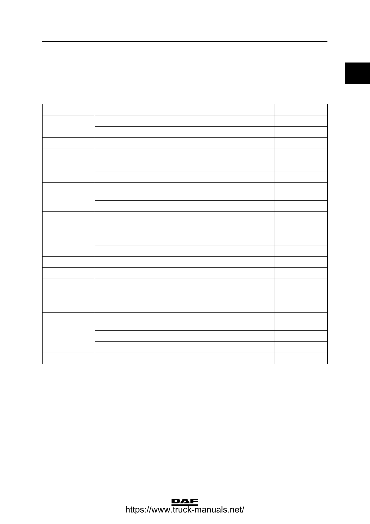
1. CHASSIS. . . . . . . . . . . . . . . . . . . . . . . . . . . . . . . . . . . . . . . . . . . . . . . . . . . . . . . 1-1 . . . . . 200448
1.1 General . . . . . . . . . . . . . . . . . . . . . . . . . . . . . . . . . . . . . . . . . . . . . . . . . . . 1-1 . . . . . 200448
2. STABILISERS, TORQUE RODS AND LEAF SUSPENSION. . . . . . . . . . . . . . . 2-1 . . . . . 200448
2.1 General . . . . . . . . . . . . . . . . . . . . . . . . . . . . . . . . . . . . . . . . . . . . . . . . . . . 2-1 . . . . . 200448
2.2 Tightening torques. . . . . . . . . . . . . . . . . . . . . . . . . . . . . . . . . . . . . . . . . . . 2-1 . . . . . 200448
3. REAR AXLE ALIGNMENT . . . . . . . . . . . . . . . . . . . . . . . . . . . . . . . . . . . . . . . . . 3-1 . . . . . 200448
3.1 General . . . . . . . . . . . . . . . . . . . . . . . . . . . . . . . . . . . . . . . . . . . . . . . . . . . 3-1 . . . . . 200448
4. FAG . . . . . . . . . . . . . . . . . . . . . . . . . . . . . . . . . . . . . . . . . . . . . . . . . . . . . . . . . . . 4-1 . . . . . 200448
4.1 General . . . . . . . . . . . . . . . . . . . . . . . . . . . . . . . . . . . . . . . . . . . . . . . . . . . 4-1 . . . . . 200448
Contents
0
©
200448 1
Page 4

TECHNICAL DATA
9
0
Contents
ΧΦ65/75/85 series
2
©
200448
Page 5
9
TECHNICAL DATA
ΧΦ65/75/85 series
1. CHASSIS
1.1 GENERAL
Chassis materials
Type Chassis type Material
FT Side member thickness 6 mm KF 600
Side member thickness 7 mm KF 500
FTG n/a KF 500
FTP n/a KF 600
FTS Side member height 260 mm KF 500
Side member height 310 mm KF 375
FTT RHD version: side member height 260 mm, side member
thickness 7 mm KF 500
Other versions KF 375
FA n/a KF 375
Chassis
0
(1)
(1)
(1)
(1)
(1)
(1)
FAC n/a KF 375
FAD Side member height 310 mm, side member thickness 6 mm KF 600
Other versions KF 375
FAG n/a KF 375
FAL n/a KF 375
FAN n/a KF 375
FAR n/a KF 375
FAS n/a KF 375
FAT RHD version: side member height 260 mm, side member
thickness 7 mm KF 500
Side member height 310 mm, side member thickness 6 mm KF 600
Other versions KF 375
FAX n/a KF 375
(1) KF 500 and KF 600 are "High Tensile Strength" types of steel.
(1)
(1)
(1)
©
200448 1-1
Page 6

TECHNICAL DATA
9
0
Chassis
ΧΦ65/75/85 series
1-2
©
200448
Page 7
9
TECHNICAL DATA
ΧΦ65/75/85 series
Stabilisers, torque rods and leaf suspension
2. STABILISERS, TORQUE RODS AND LEAF SUSPENSION
2.1 GENERAL
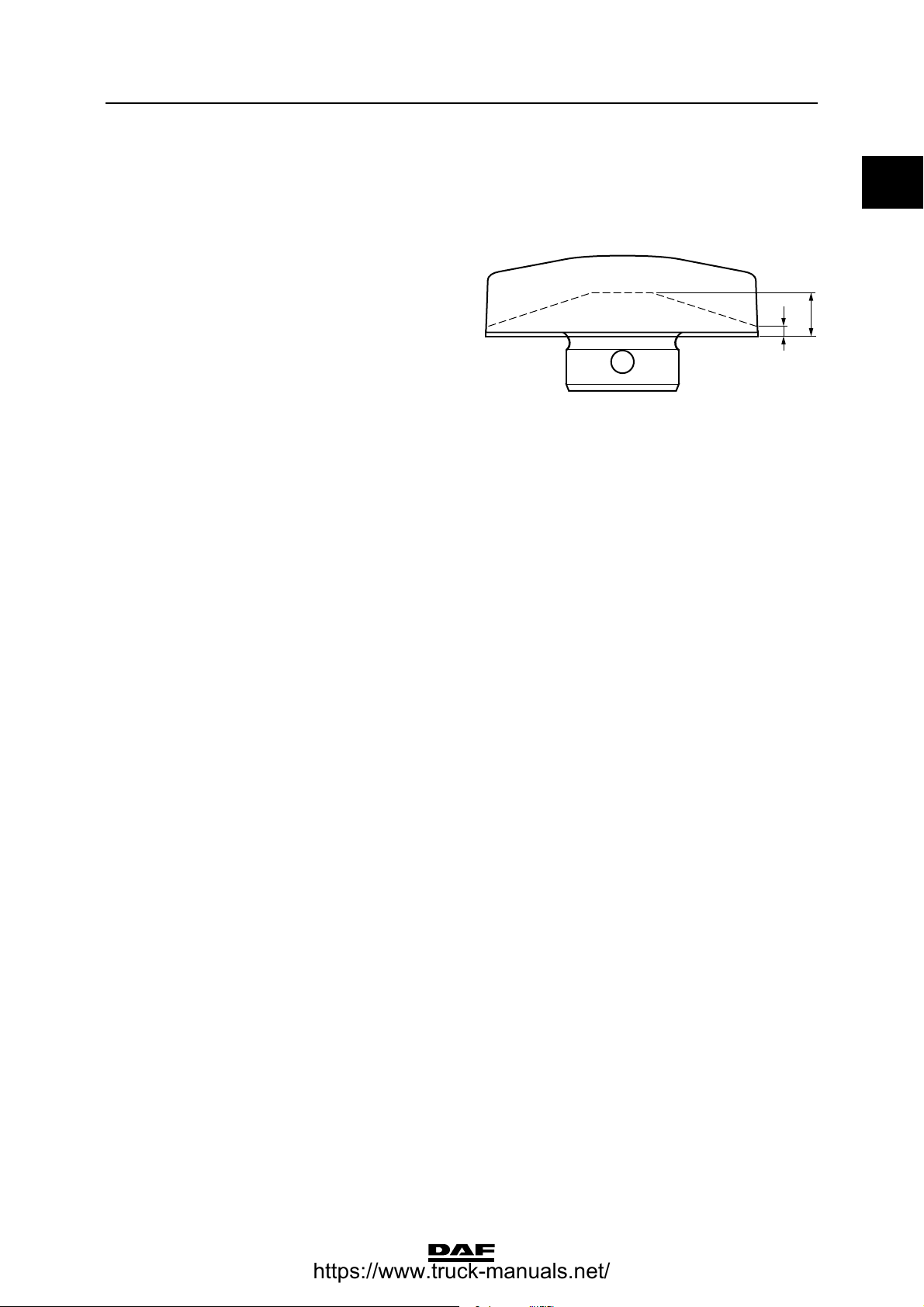
Minimum dimensions of wearing plates
If one of the dimensions of the wearing plates, on
which the spring assembly rests, is smaller than
indicated by the dotted line in the opposite
drawing, the wearing plates must be replaced.
Alignment plate/tandem axle spring clearance
If applicable, the clearance between the alignment plate and the tandem axle is: 1.5 - 2.5 mm.
2.2 TIGHTENING TORQUES
3
W9 00 013
0
15
The tightening torques stated in this section are
different from the standard tightening torques
stated in the overview of the standard tightening
torques. The other threaded connections not
specified must therefore be tightened to the
torque stated in the overview of standard
tightening torques.
When attachment bolts and nuts are replaced, it
is important that - unless stated otherwise - these
bolts and nuts are of exactly the same length and
property class as those removed.
©
200448 2-1
Page 8
TECHNICAL DATA
9
0
Stabilisers, torque rods and leaf suspension
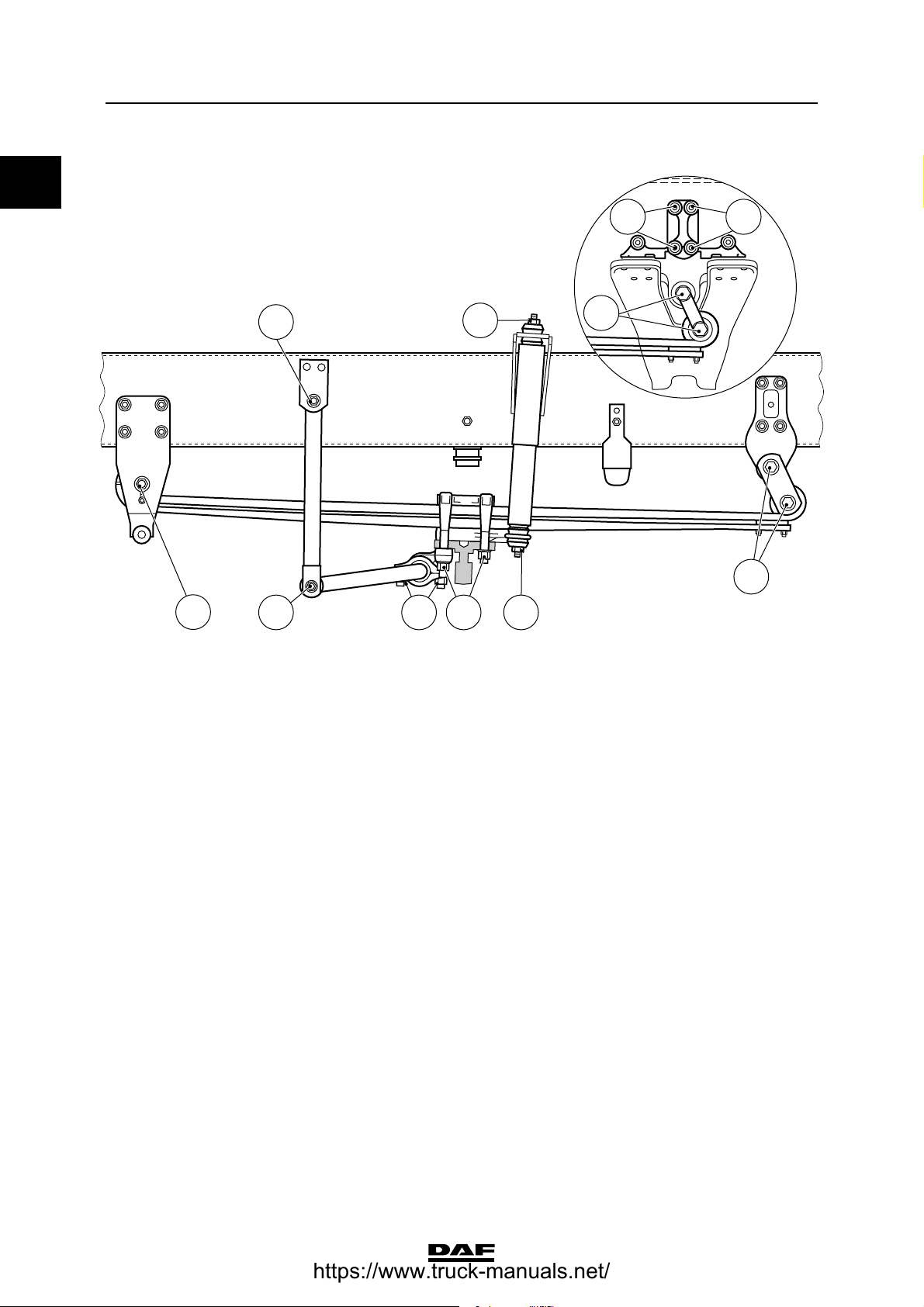
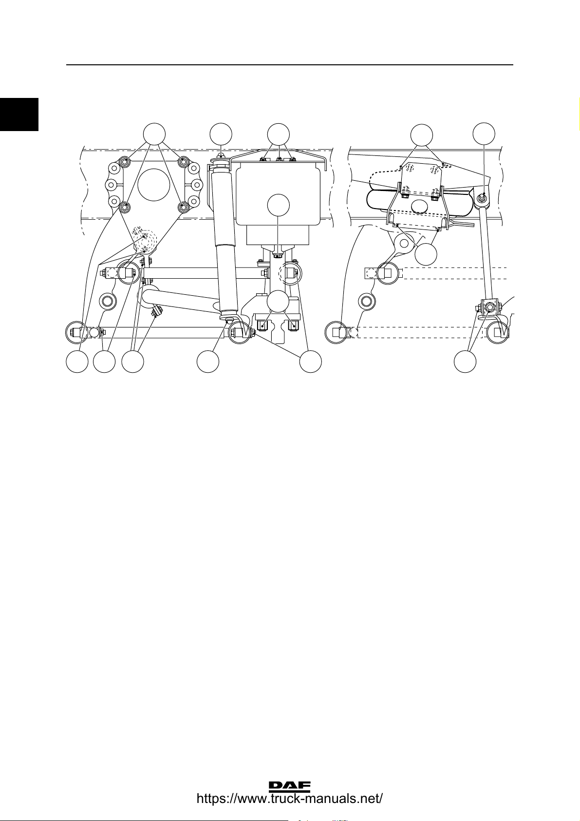
Front axle, leaf-sprung
D
C
ΧΦ65/75/85 series
F F
A
A
A Attachment bolt M24 for spring assembly,
property class 10.9 880 Nm
B U-bolt nut
- if flange nut M20, with yellow washer 450 ≥ 40 Nm
- if yellow zinc-plated hexagonal nut
M20, property class 10, with black
washer 400 ≥ 40 Nm
C Self-locking nut M16 for shock absorber 65 Nm
D Attachment bolt/nut M16 for stabiliser rod
shackle, property class 10.9/10 260 ≥ 20 Nm
E Attachment bolt/nut M12 for stabiliser rod
bearing bush cover, property class 10.9/10 110 ≥ 8 Nm
F Attachment bolt/nut M14 for spring
bracket, property class 10.9/10 170 ≥ 15 Nm
(1) Evenly tighten the two U-bolt nuts alternately.
(2) Only applies in case of tandem axle/trailing axle
D
E
B C
A
C9 00 477
(1)
(1)
(2)
2-2
©
200448
Page 9
9
TECHNICAL DATA
ΧΦ65/75/85 series
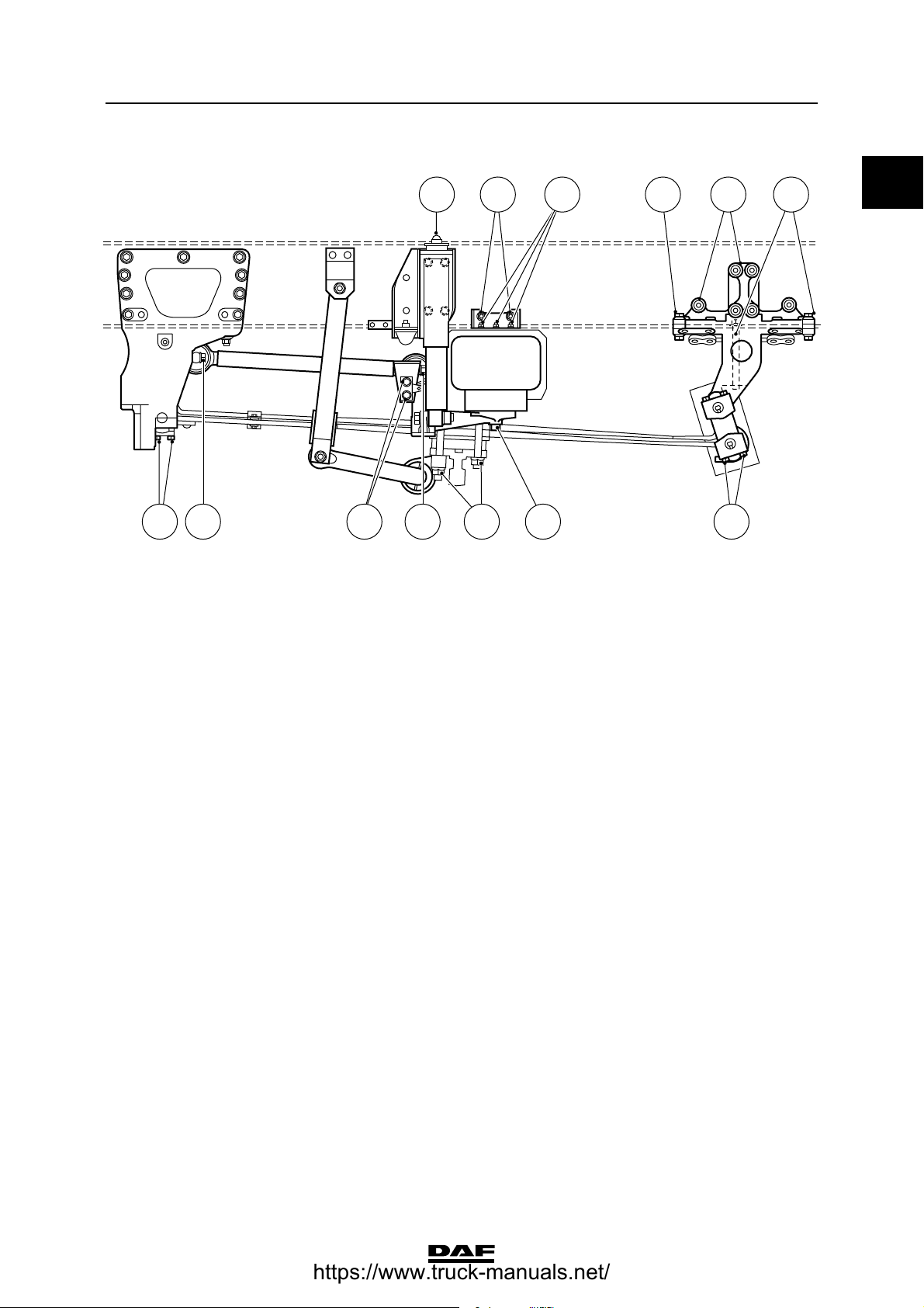
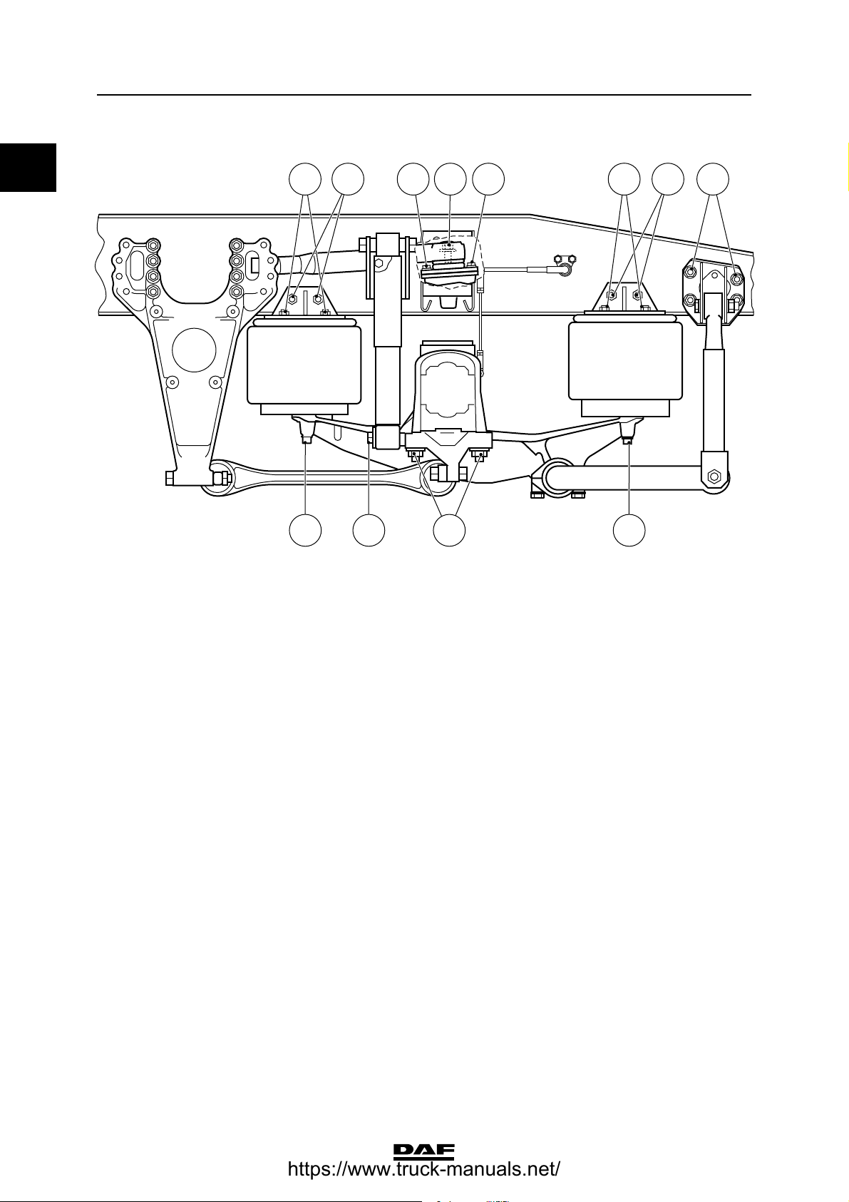
Front axle, air-sprung
A AJ B C I
I
Stabilisers, torque rods and leaf suspension
FH DG E E
C9 00 479
0
A Attachment bolt M16 for torque rod,
property class 10.9 260 ≥ 20 Nm
B U-bolt nut
- if flange nut M22 700 ≥ 50 Nm
- if yellow zinc-plated hexagonal nut
M22, property class 10, with black
washer 530 ≥ 40 Nm
C Attachment bolt M16 for bellows, property
class 8.8 195 Nm
D Attachment nut M10 for bellows, property
class 10 46 Nm
E Attachment bolt/nut M16 for spring
bracket, property class 10.9/10 260 ≥ 20 Nm
F Attachment bolt/nut M14 for spring
bracket, property class 10.9/10 170 ≥ 15 Nm
G Self-locking nut M16 for shock absorber 65 Nm
H Attachment bolt/nut M12 for bellows
support, property class 10.9/10 110 ≥ 8 Nm
I Attachment bolt M10 for pin attachment of
spring assembly, property class 10.9 60 ≥ 4 Nm
J Attachment bolt M12 for torque rod
support, property class 10.9 110 ≥ 8 Nm
(1) Evenly tighten the two U-bolt nuts alternately.
(2) Bellows must first be tightened on the chassis side.
(1)
(1)
(2)
(2)
©
200448 2-3
Page 10
TECHNICAL DATA
9
0
Stabilisers, torque rods and leaf suspension
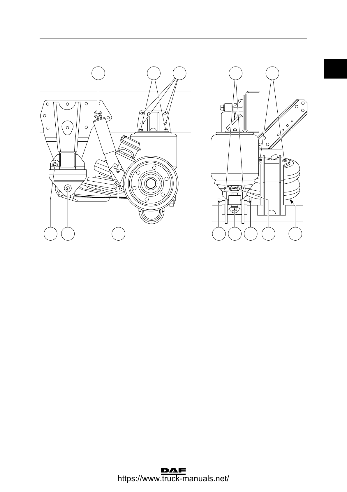
Leading rear axle, vehicle in FTG, FAG
version
A B
C
D
E
ΧΦ65/75/85 series
F
A
F
GH A
A Attachment bolt/nut M16 for torque rod
(support), property class 10.9/10 260 ≥ 20 Nm
B Self-locking nut M16 for shock absorber 65 Nm
C Attachment nut M10 for bellows, property
class 10 46 Nm
D Attachment bolt M16 for bellows, property
class 10.9 195 Nm
E U-bolt nut
- if flange nut M22 700 ≥ 50 Nm
- if yellow zinc-plated hexagonal nut
M22, property class 10, with black
washer 530 ≥ 40 Nm
F Attachment bolt M8 for lifting bellows,
property class 10.9 20 Nm
G Attachment bolt/nut for stabiliser bar
bracket
- if M14, property class 10.9/10 170 ≥ 15 Nm
- if M16, property class 10.9/10 260 ≥ 20 Nm
H Attachment bolts M8 for locking plate,
property class 10.9 30 Nm
(1) Bellows must first be tightened on the chassis side.
(2) Evenly tighten the two U-bolt nuts alternately.
BA A
C9 00 486
(1)
(1)
(2)
(2)
2-4
©
200448
Page 11
9
TECHNICAL DATA
ΧΦ65/75/85 series
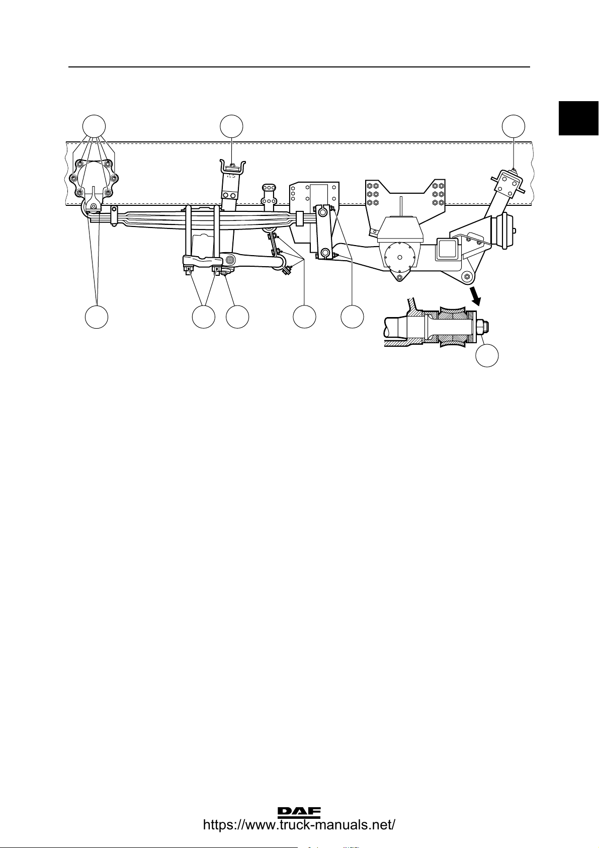
Leading rear axle, vehicle in FTP version
A
Stabilisers, torque rods and leaf suspension
B I DC
0
A Attachment bolt M20 for shock absorber,
property class 8.8 250 ≥ 25 Nm
B Attachment nut M12 for bellows 30 Nm
C U-bolt nut M20, property class 10.9 553 Nm
D Attachment nut M10 for bellows 30 Nm
E Attachment bolt M16 for leaf spring,
property class 10.9 100 Nm
F Attachment bolt/nut M20 for leaf spring,
property class 10.9/10 553 Nm
G Attachment bolt/nut M24 for leaf spring 830 Nm
H Attachment bolt/nut M16 for spring
bracket, property class 10.9 310 Nm
I Attachment bolt/nut M10 for bellows
support, property class 10.9/10 60 ≥ 4 Nm
(1) Evenly tighten the two U-bolt nuts alternately.
DEFEAG BH
C9 00 481
(1)
©
200448 2-5
Page 12
TECHNICAL DATA
9
0
Stabilisers, torque rods and leaf suspension
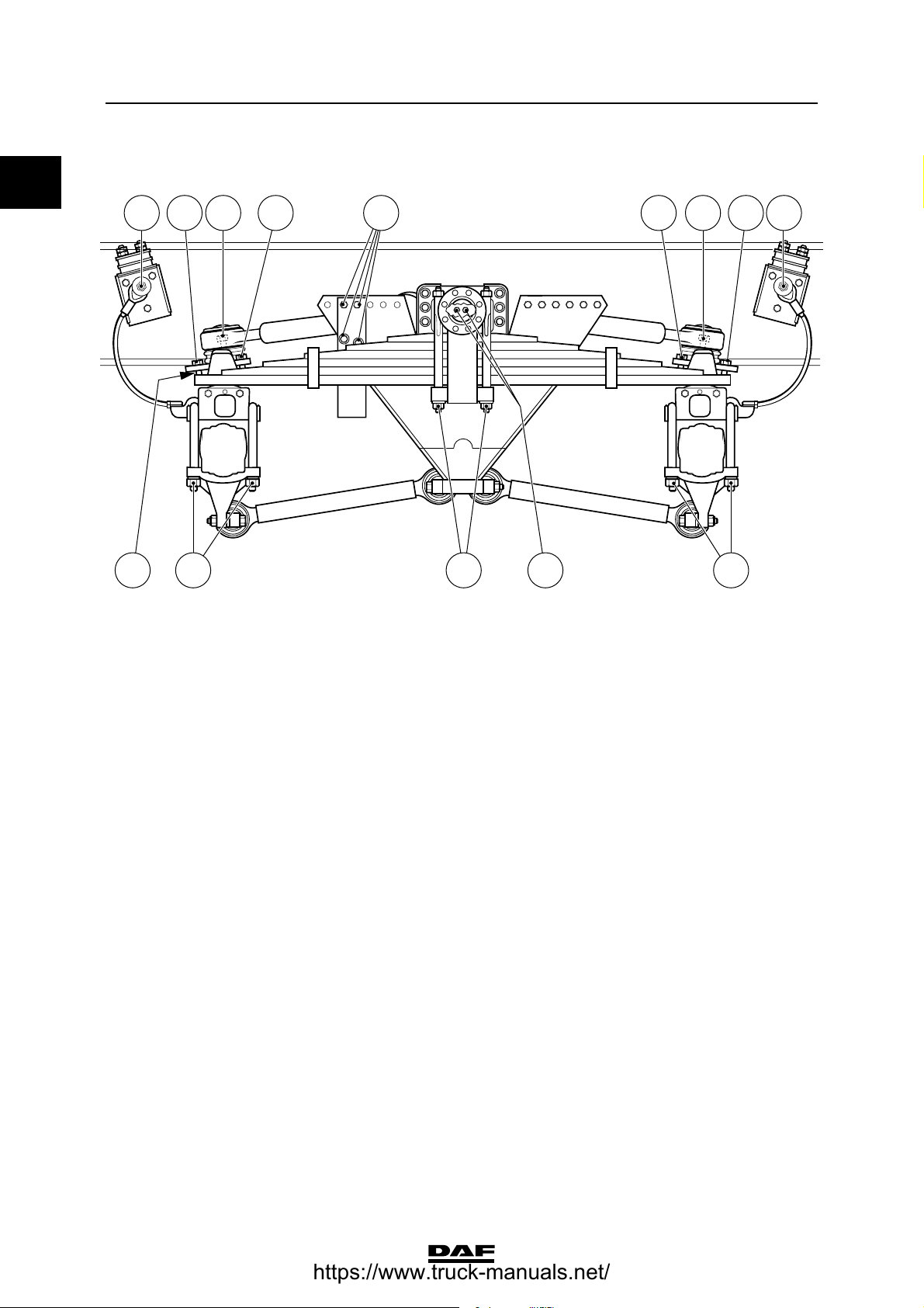
Double front axle
CF F C
A
A Attachment bolt M24 for spring assembly,
property class 10.9 880 Nm
B U-bolt nut
- if flange nut M20, with yellow washer 450 ≥ 40 Nm
- if yellow zinc-plated hexagonal nut
M20, property class 10, with black
washer 400 ≥ 40 Nm
C Self-locking nut M16 65 Nm
D Ball end nut
- if self-locking nut 285 Nm
- if castle nut 285 Nm
E Attachment bolt/nut M12 for stabiliser rod
bearing bush cover, property class 10.9/10 110 ≥ 8 Nm
F Attachment bolt/nut M16 for stabiliser rod
shackle, property class 10.9/10 260 ≥ 20 Nm
BEF EFA B C A DD AC
ΧΦ65/75/85 series
C900465
(1)
(1)
(2)
(3)
(1) Evenly tighten the two U-bolt nuts alternately.
(2) Fit new self-locking nut.
(3) Tighten until the split pin fits (max. 60).
It is not allowed to fit a self-locking nut to the ball
end with split pin hole.
2-6
©
200448
Page 13
9
TECHNICAL DATA
ΧΦ65/75/85 series
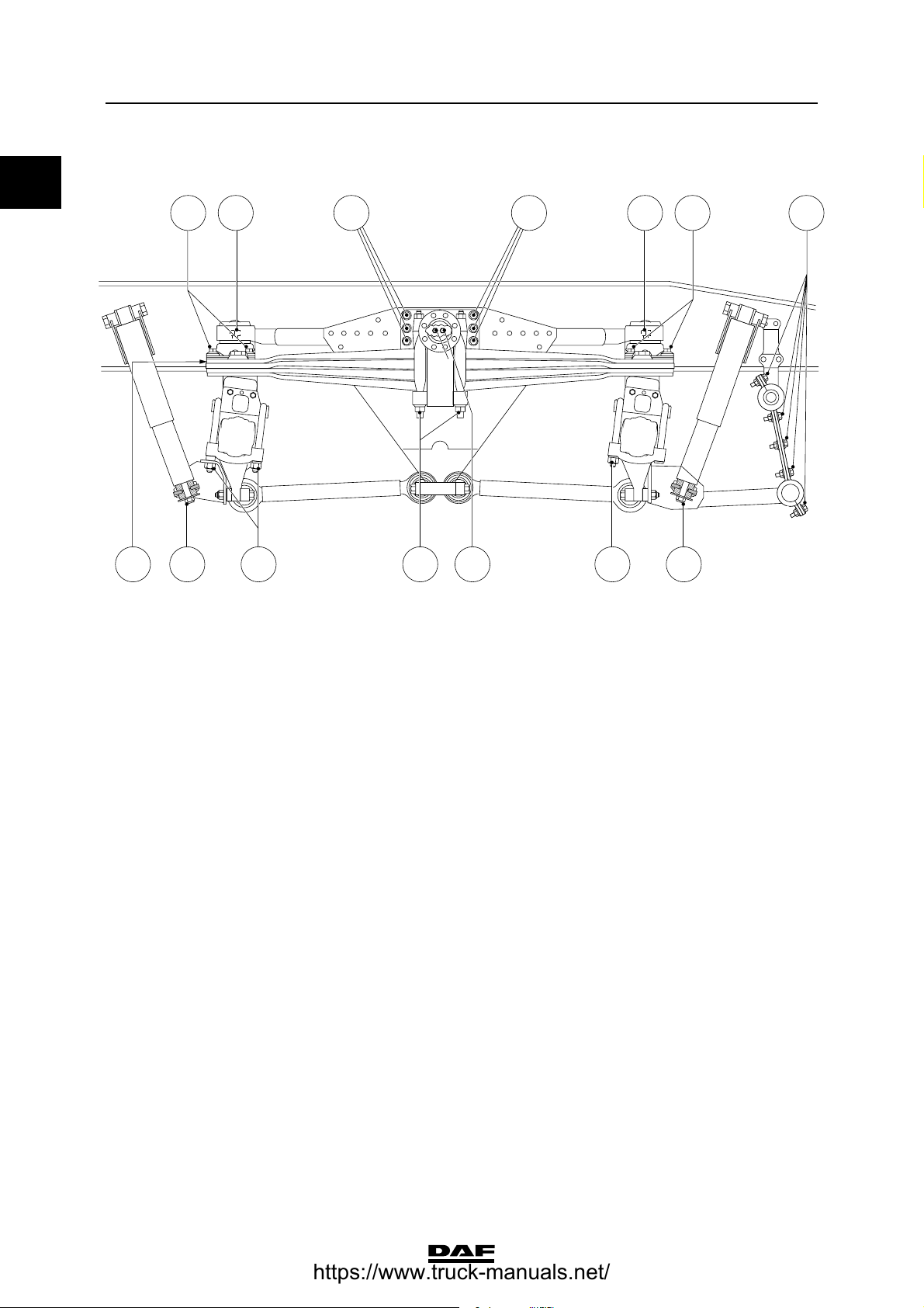
Rear axle, leaf suspension
Stabilisers, torque rods and leaf suspension
DA A
B
C D F
A Attachment bolt/nut M16 for spring
bracket, property class 10.9/10 260 ≥ 20 Nm
B Attachment bolt M24 for spring assembly,
property class 10.9 880 Nm
C U-bolt nut
- if flange nut M24, with black washer 750 ≥ 50 Nm
- if yellow zinc-plated hexagonal nut
M24, property class 10, with black
washer 615 ≥ 50 Nm
D Self-locking nut M16 for shock absorber 65 Nm
E Catch bolt M12, property class 10.9 68 ≥ 12 Nm
F Attachment bolt/nut M14 for stabiliser rod
bracket, property class 10.9/10 170 ≥ 15 Nm
0
A
E
A
B
C9 00 478
(1)
(1)
(1) Evenly tighten the two U-bolt nuts alternately.
©
200448 2-7
Page 14
TECHNICAL DATA
9
0
Stabilisers, torque rods and leaf suspension
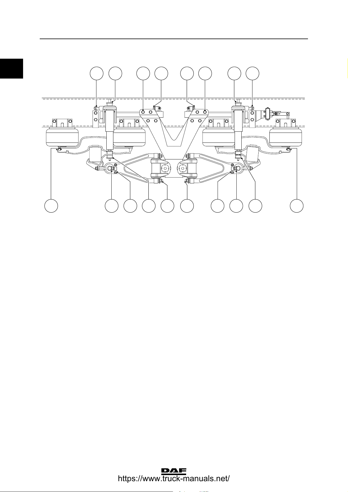
Rear axle, air-sprung
A H H
ΧΦ65/75/85 series
AEE F G
DCB B
C9 00 480
A Attachment nut M10 for bellows, property
class 10 46 Nm
B Attachment bolt M16 for bellows, property
class 8.8 195 Nm
C Attachment bolt M20 for shock absorber,
property class 10.9 520 ≥ 40 Nm
D U-bolt nut
- if black high hexagonal nut M24 with
black washer 770 ≥ 60 Nm
- if yellow zinc-plated hexagonal nut
M24, property class 10, with black
washer 615 ≥ 50 Nm
E Clamping flange bolt M18 for triangular
link, property class 12.9 460 ≥ 40 Nm
F Attachment bolt M14, for triangular link
ball, property class 10.9 135 Nm
G Attachment bolt/nut M16 for stabiliser
shackle support, property class 10.9/10 260 ≥ 20 Nm
H Attachment bolt/nut M10 for bellows
support, property class 10.9/10 60 ≥ 4 Nm
(1) Bellows must first be tightened on the chassis side.
(2) The high hexagonal nut can be recognised by the nut height, which is 1.5 x thread . Evenly tighten the two U-bolt nuts
alternately.
(3) The yellow zinc-plated hexagonal nut can be recognised by the nut height, which is 1 x thread . Evenly tighten the two U-bolt
nuts alternately.
(1)
(1)
(2)
(3)
2-8
©
200448
Page 15
9
TECHNICAL DATA
ΧΦ65/75/85 series
Trailing axle, leaf suspension
D
F
A U-bolt nut
- if flange nut M24 750 ≥ 50 Nm
- if yellow zinc-plated hexagonal nut
M24, property class 10, with black
washer 615 ≥ 50 Nm
B Self-locking nut M16 65 Nm
C Shock absorber attachment nut 260 ≥ 20 Nm
D Attachment bolt/nut M16 for spring
bracket, property class 10.9/10 260 ≥ 20 Nm
E Attachment bolt/nut M14 for stabiliser rod
bracket, property class 10.9/10 170 ≥ 15 Nm
F Attachment bolt M10 for pin attachment of
spring assembly, property class 10.9 60 ≥ 4 Nm
G Attachment bolt/nut M12 for spring
shackle, property class 10.9/10 110 ≥ 8 Nm
B
A B
Stabilisers, torque rods and leaf suspension
E G
(1)
(1)
C
B
C9 00 483
0
(1) Evenly tighten the two U-bolt nuts alternately.
©
200448 2-9
Page 16
TECHNICAL DATA
9
0
Stabilisers, torque rods and leaf suspension
Trailing axle, air-sprung, 6 bellows version
A BI H A
E F E
A Attachment nut M10 for bellows, property
class 10 46 Nm
B Clamping flange bolt M18 for triangular
link, property class 12.9 460 ≥ 40 Nm
C Attachment bolt M14, for triangular link
ball, property class 10.9 135 Nm
D U-bolt nut
- if black high hexagonal nut M24 with
black washer 770 ≥ 60 Nm
- if yellow zinc-plated hexagonal nut
M24, property class 10, with black
washer 615 ≥ 50 Nm
E Attachment bolt M16 for bellows, property
class 8.8 195 Nm
F Attachment bolt M20 for shock absorber,
property class 10.9 520 ≥ 40 Nm
G Attachment bolt/nut M16 for stabiliser
shackle support, property class 10.9/10 260 ≥ 20 Nm
H Attachment bolt/nut M10 for bellows
support, property class 10.9/10 60 ≥ 4 Nm
I Attachment bolt/nut M16 for stabiliser
shackle support, property class 10.9/10 260 ≥ 20 Nm
C
D
(1)
(1)
A
E
(2)
(3)
ΧΦ65/75/85 series
C
B G
D
C900463
(1) Bellows must first be tightened on the chassis side.
(2) The high hexagonal nut can be recognised by the nut height, which is 1.5 x thread . Evenly tighten the two U-bolt nuts
alternately.
(3) The yellow zinc-plated hexagonal nut can be recognised by the nut height, which is 1 x thread . Evenly tighten the two U-bolt
nuts alternately.
2-10
©
200448
Page 17
9
TECHNICAL DATA
ΧΦ65/75/85 series
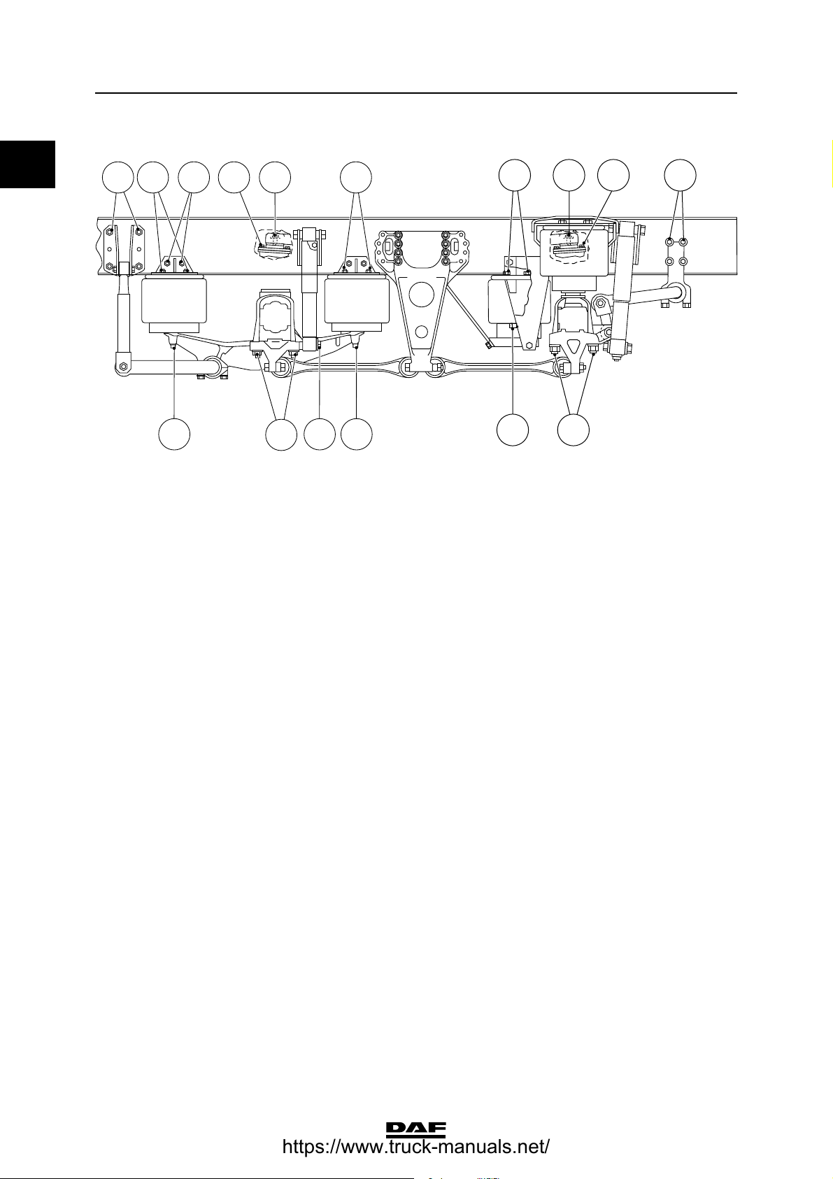
Trailing axle, air-sprung, 8 bellows version
A B C BCG H GA
D DDF FD D
A Attachment nut M10 for bellows, property
class 10 46 Nm
B Clamping flange bolt M18 for triangular
link, property class 12.9 460 ≥ 40 Nm
C Attachment bolt M14, for triangular link
ball, property class 10.9 135 Nm
D Attachment bolt M16 for bellows, property
class 8.8 195 Nm
E U-bolt nut
- if black high hexagonal nut M24 with
black washer 770 ≥ 60 Nm
- if yellow zinc-plated hexagonal nut
M24, property class 10, with black
washer 615 ≥ 50 Nm
F Attachment bolt M20 for shock absorber,
property class 10.9 520 ≥ 40 Nm
G Attachment bolt/nut M16 for stabiliser
shackle support, property class 10.9/10 260 ≥ 20 Nm
H Attachment bolt/nut M10 for bellows
support, property class 10.9/10 60 ≥ 4 Nm
HHH
E E
Stabilisers, torque rods and leaf suspension
A AA
(1)
(1)
(2)
(3)
0
C9 00 482
(1) Bellows must first be tightened on the chassis side.
(2) The high hexagonal nut can be recognised by the nut height, which is 1.5 x thread . Evenly tighten the two U-bolt nuts
alternately.
(3) The yellow zinc-plated hexagonal nut can be recognised by the nut height, which is 1 x thread . Evenly tighten the two U-bolt
nuts alternately.
©
200448 2-11
Page 18
TECHNICAL DATA
9
0
Stabilisers, torque rods and leaf suspension
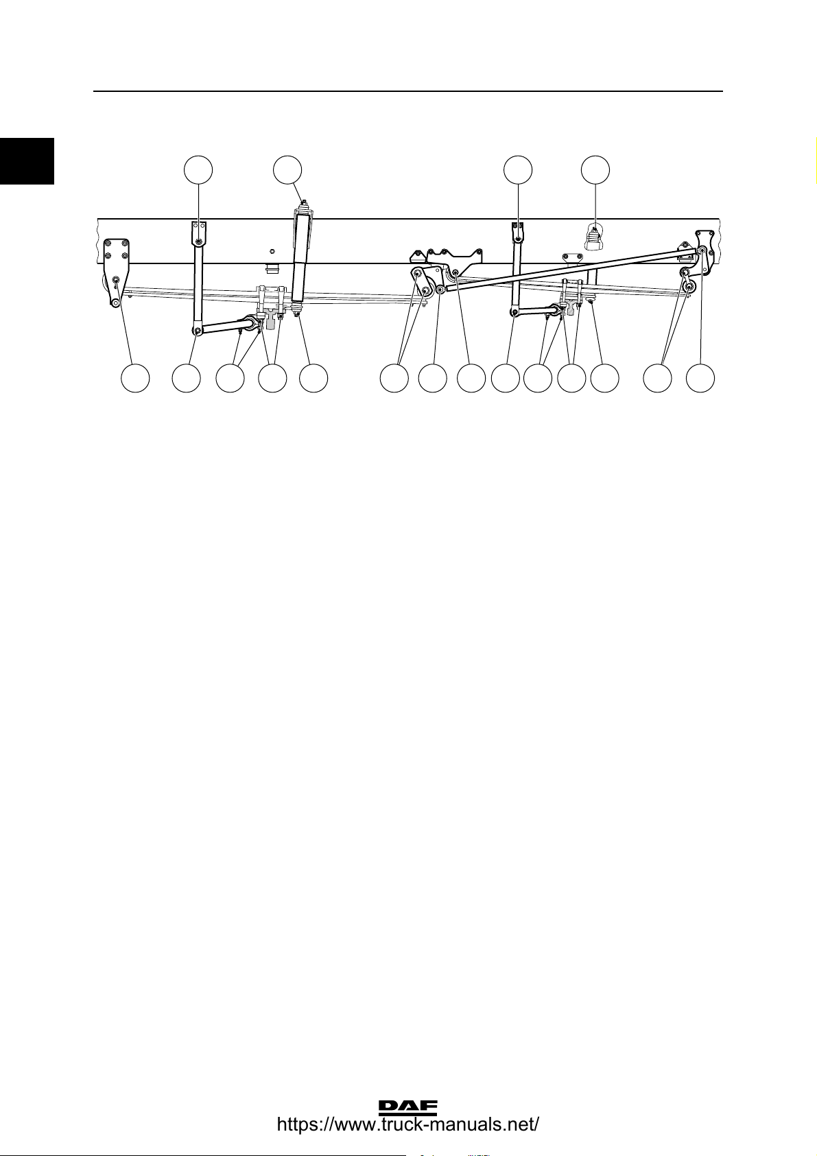
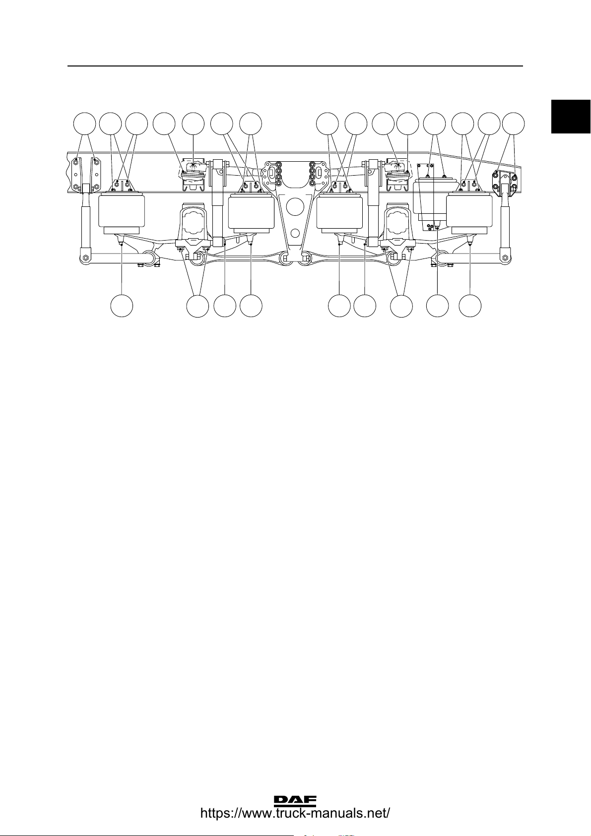
Tandem axle, leaf-sprung, trapezoidal leaf
spring version
A C
ΧΦ65/75/85 series
C B
ABC CG
FH
A Attachment bolt/nut M16 for arresting
cable 150 ≥ 20 Nm
B Attachment bolt M14, for triangular link
ball, property class 10.9 135 Nm
C Clamping flange bolt M18 for triangular
link, property class 12.9 460 ≥ 40 Nm
D U-bolt nut
- if flange nut M20 450 ≥ 40 Nm
- if yellow zinc-plated hexagonal nut
M20, property class 10, with black
washer 400 ≥ 40 Nm
E Attachment bolt M14, for bearing bush
plate, property class 10.9 170 ≥ 15 Nm
F Tie rod nut
if flange nut M22 650 ≥ 50 Nm
if yellow zinc-plated hexagonal nut M22,
property class 10, with black washer 480 ≥ 40 Nm
G Attachment bolt/nut M12 for alignment
plate, property class 10.9/10 110 ≥ 8 Nm
E
DD
C9 00 485
(1)
(1)
(2)
(1)
(1)
2-12
©
200448
Page 19

9
TECHNICAL DATA
ΧΦ65/75/85 series
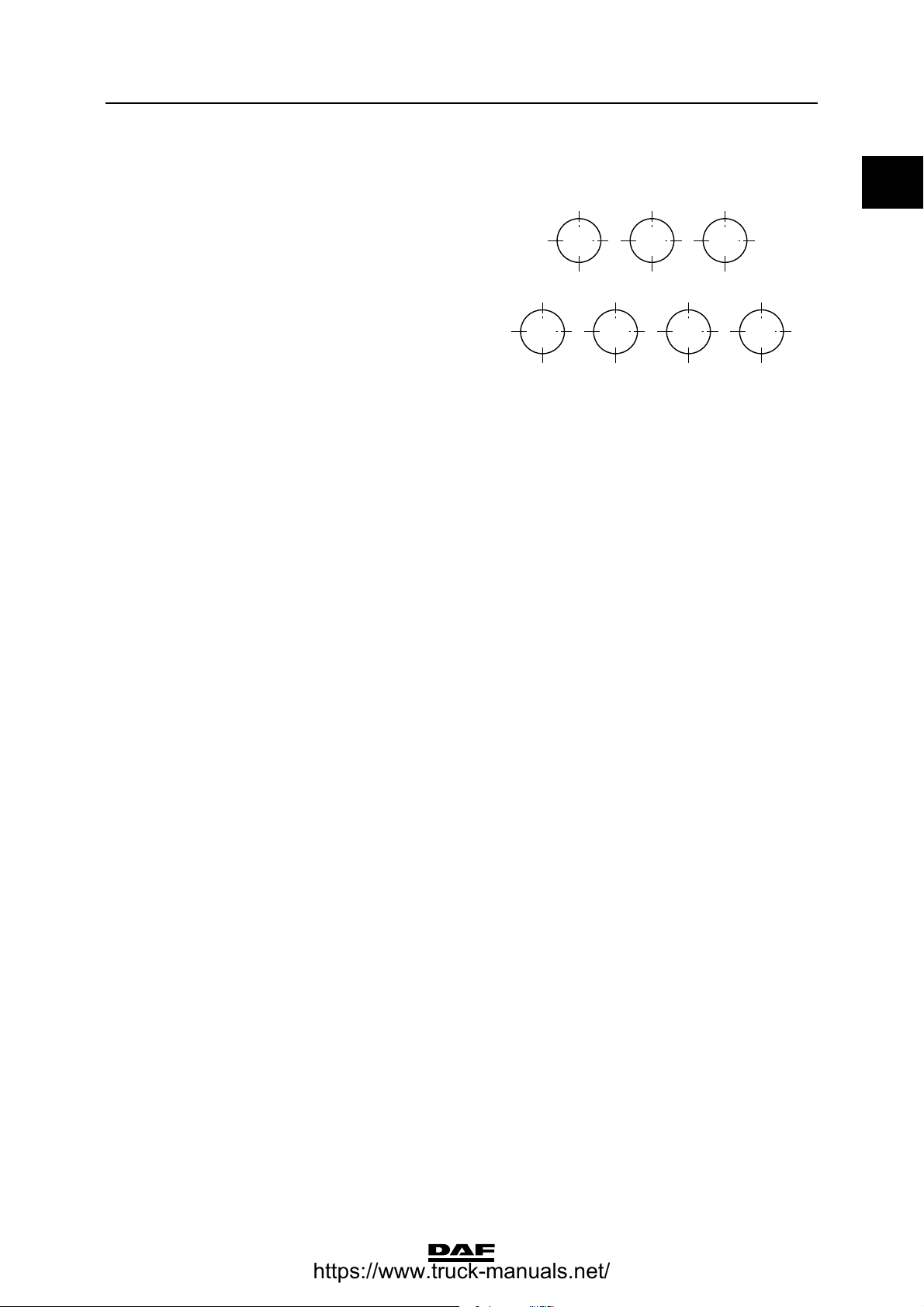
H Tighten the bolts according to the standard
tightening torque, in the order shown.
(1) Evenly tighten the two U-bolt/tie rod nuts alternately.
(2) Fasten with Loctite 243.
Stabilisers, torque rods and leaf suspension
0
4 1 5
7 2 3 6
C9 00 144
©
200448 2-13
Page 20
TECHNICAL DATA
9
0
Stabilisers, torque rods and leaf suspension
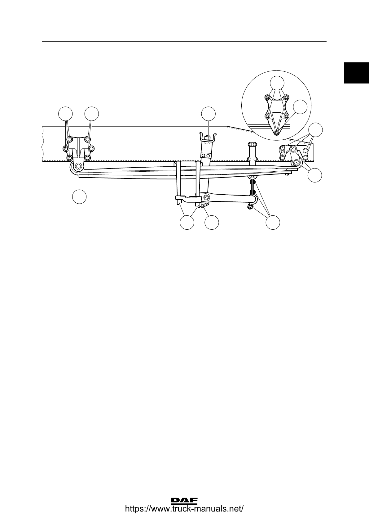
Tandem axle, leaf-sprung, parabolic leaf
spring version
A B AB
G
ΧΦ65/75/85 series
HG
C CDFI E
A Clamping flange bolt M18 for triangular
link, property class 12.9 460 ≥ 40 Nm
B Attachment bolt M14, for triangular link
ball, property class 10.9 135 Nm
C Self-locking nut M16 for shock absorber 65 Nm
D U-bolt nut
- if flanged nut 450 ≥ 40 Nm
- if yellow zinc-plated hexagonal nut
M20, property class 10, with black
washer 400 ≥ 40 Nm
E Attachment bolt M14, for bearing bush
plate, property class 10.9 170 ≥ 15 Nm
F Tie rod nut
- if flanged nut 650 ≥ 50 Nm
- if yellow zinc-plated hexagonal nut
M22, property class 10, with black
washer 480 ≥ 40 Nm
G Attachment bolt M16 for pivot pin flange,
property class 10.9 260 ≥ 20 Nm
H Attachment bolt/nut M14 for stabiliser rod
bracket, property class 10.9/10 170 ≥ 15 Nm
D
C9 00 484
(1)
(1)
(2)
(1)
(1)
2-14
©
200448
Page 21
9
TECHNICAL DATA
ΧΦ65/75/85 series
I Tighten the bolts according to the standard
tightening torque, in the order shown.
(1) Evenly tighten the two U-bolt/tie rod nuts alternately.
(2) Fasten with Loctite 243.
Stabilisers, torque rods and leaf suspension
0
4 1 5
7 2 3 6
C9 00 144
©
200448 2-15
Page 22
TECHNICAL DATA
9
0
Stabilisers, torque rods and leaf suspension
Tandem axle, air-sprung, Meritor version
A B
C A A C B A
D E F B BG
A Attachment bolt/nut M16 for torque rod,
property class 10.9/10 260 ≥ 60 Nm
B Tighten shock absorber attachment nut
until the rubber sleeve and the steel ring
have the same diameter.
C Attachment bolt/nut M22 for yoke, property
class 10.9/10 750 Nm
D Attachment bolt for bellows 1/2" UNC 34 ≥ 7 Nm
E Attachment bolt/nut M16 for torque rod,
property class 10.9/10 260 ≥ 60 Nm
F Attachment bolt/nut M10 for torque rod,
property class 10.9/10 60 ≥ 4 Nm
G Attachment nut M20 for torque rod,
property class 10.9 520 ≥ 40 Nm
ΧΦ65/75/85 series
FE DG
C9 00 404
2-16
©
200448
Page 23
9
TECHNICAL DATA
ΧΦ65/75/85 series
3. REAR AXLE ALIGNMENT
3.1 GENERAL
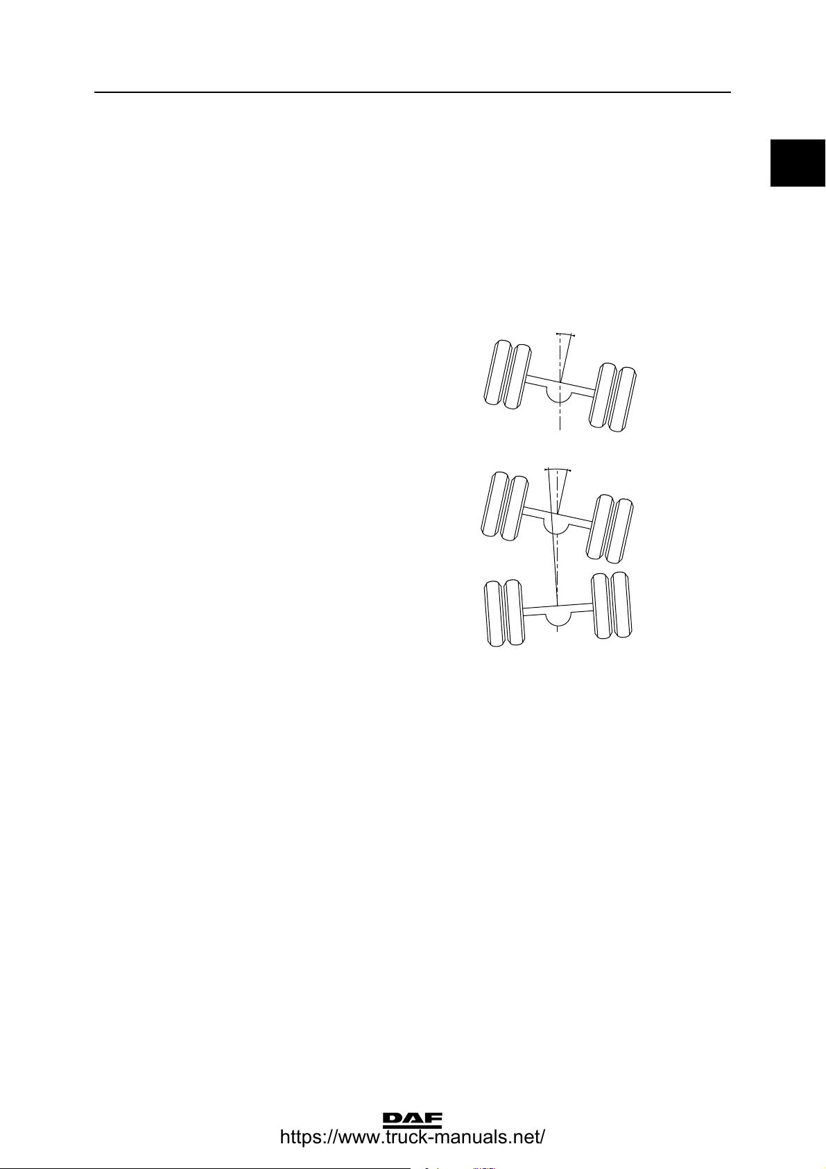
Rear axle misalignment standard
The angle achieved by the driven rear axle
relative to the vehicle centreline is calculated
from the angle achieved by both wheels of this
axle relative to the vehicle centreline. See "Rear
axle alignment".
Driven axle relative to the vehicle centreline:
- max. 4 mm/m (angle A in drawing).
This value also applies to the individual
tandem axles and the driven axle of the
trailing axle suspension.
Non-parallelism of the rear tandem axle relative
to the front tandem axle:
- max. 2 mm/m (angle B in drawing).
Rear axle alignment
0
A
C9 00 123
B
C9 00 124
©
200448 3-1
Page 24
TECHNICAL DATA
9
0
Rear axle alignment
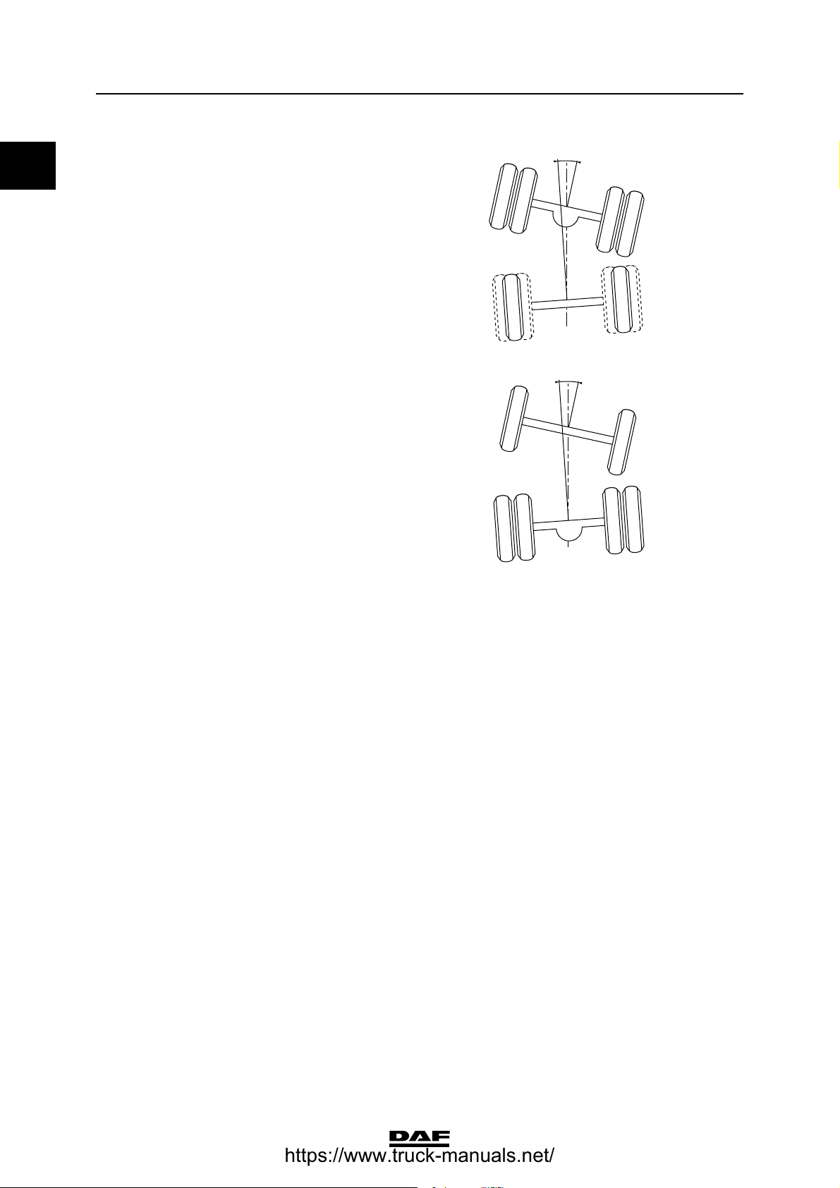
Non-parallelism of the trailing axle relative to the
driven axle:
- max. 2 mm/m (angle C in drawing).
Non-parallelism of the unsteered leading rear
axle (FTP) relative to the driven axle:
- max. 2 mm/m (angle D in drawing).
ΧΦ65/75/85 series
C
C9 00 235
D
C9 00 519
3-2
©
200448
Page 25
9
TECHNICAL DATA
ΧΦ65/75/85 series
4. FAG
4.1 GENERAL
Valve adjustment
Pressure-limiting valve 7.0 bar
Pressure-relief valve 0.5 bar
Control values/adjustment of height-control
valve, axle load ratio 6.0/10.0 and fitted with
leaf spring suspension (DAF no. 1368293)
Lever length 60 mm
Joint axle load of leading rear axle/
drive shaft (N)
30,000 0.4
40,000 0.7
50,000 1.1
60,000 1.5
FAG
0
Bellows pressure (bar)
70,000 1.9
80,000 2.2
90,000 2.6
100,000 3.0
110,000 3.4
120,000 3.7
130,000 4.1
140,000 4.5
150,000 4.9
160,000 5.2
170,000 5.6
180,000 6.0
190,000 6.4
200,000 6.7
©
200448 4-1
Page 26

TECHNICAL DATA
9
0
FAG
Control values/adjustment of height-control
valve, axle load ratio 6.0/10.0 and fitted with
leaf spring suspension (DAF no. 1386990)
Lever length 70 mm
Joint axle load of leading rear axle/
drive shaft (N)
30,000 0.4
40,000 0.7
50,000 1.1
60,000 1.5
70,000 1.9
80,000 2.2
90,000 2.6
100,000 3.0
110,000 3.4
ΧΦ65/75/85 series
Bellows pressure (bar)
120,000 3.7
130,000 4.1
140,000 4.5
150,000 4.9
160,000 5.2
170,000 5.6
180,000 6.0
190,000 6.4
200,000 6.7
4-2
©
200448
Page 27

9
TECHNICAL DATA
ΧΦ65/75/85 series
Control values/adjustment of height-control
valve, axle load ratio 7.1/11.5 and fitted with
leaf spring suspension (DAF no. 1368293)
Lever length 60 mm
Joint axle load of leading rear axle/
drive shaft (N)
30,000 0.4
40,000 0.8
50,000 1.1
60,000 1.5
70,000 1.9
80,000 2.3
90,000 2.7
100,000 3.1
110,000 3.4
FAG
0
Bellows pressure (bar)
120,000 3.8
130,000 4.2
140,000 4.6
150,000 5.0
160,000 5.3
170,000 5.7
180,000 6.1
190,000 6.5
200,000 6.9
©
200448 4-3
Page 28

TECHNICAL DATA
9
0
FAG
Control values/adjustment of height-control
valve, axle load ratio 7.1/11.5 and fitted with
leaf spring suspension (DAF no. 1386990)
Lever length 70 mm
Joint axle load of leading rear axle/
drive shaft (N)
30,000 0.4
40,000 0.8
50,000 1.1
60,000 1.5
70,000 1.9
80,000 2.3
90,000 2.7
100,000 3.1
110,000 3.4
ΧΦ65/75/85 series
Bellows pressure (bar)
120,000 3.8
130,000 4.2
140,000 4.6
150,000 5.0
160,000 5.3
170,000 5.7
180,000 6.1
190,000 6.5
200,000 6.9
4-4
©
200448
Page 29

9
TECHNICAL DATA
ΧΦ65/75/85 series
Control values/adjustment of height-control
valve, axle load ratio 7.5/11.5 and fitted with
leaf spring suspension (DAF no. 1368293)
Lever length 60 mm
Joint axle load of leading rear axle/
drive shaft (N)
30,000 0.4
40,000 0.8
50,000 1.2
60,000 1.6
70,000 2.0
80,000 2.4
90,000 2.8
100,000 3.2
110,000 3.6
FAG
0
Bellows pressure (bar)
120,000 4.0
130,000 4.4
140,000 4.8
150,000 5.2
160,000 5.5
170,000 5.9
180,000 6.3
190,000 6.7
200,000 7.0
©
200448 4-5
Page 30

TECHNICAL DATA
9
0
FAG
Control values/adjustment of height-control
valve, axle load ratio 7.5/11.5 and fitted with
leaf spring suspension (DAF no. 1368293)
Lever length 70 mm
Joint axle load of leading rear axle/
drive shaft (N)
30,000 0.3
40,000 0.7
50,000 1.1
60,000 1.4
70,000 1.8
80,000 2.4
90,000 2.5
100,000 2.9
110,000 3.3
ΧΦ65/75/85 series
Bellows pressure (bar)
120,000 3.6
130,000 4.0
140,000 4.4
150,000 4.7
160,000 5.1
170,000 5.5
180,000 5.8
190,000 6.2
200,000 6.6
4-6
©
200448
Page 31

9
TECHNICAL DATA
ΧΦ65/75/85 series
Control values/adjustment of height-control
valve, axle load ratio 7.5/11.5 and fitted with
leaf spring suspension (DAF no. 1386990)
Lever length 70 mm
Joint axle load of leading rear axle/
drive shaft (N)
30,000 0.4
40,000 0.8
50,000 1.2
60,000 1.6
70,000 2.0
80,000 2.4
90,000 2.8
100,000 3.2
110,000 3.6
FAG
0
Bellows pressure (bar)
120,000 4.0
130,000 4.4
140,000 4.8
150,000 5.2
160,000 5.5
170,000 5.9
180,000 6.3
190,000 6.7
200,000 7.0
©
200448 4-7
Page 32

TECHNICAL DATA
9
0
FAG
Control values/adjustment of height-control
valve, axle load ratio 7.5/11.5 and fitted with
leaf spring suspension (DAF no. 1386990)
Lever length 80 mm
Joint axle load of leading rear axle/
drive shaft (N)
30,000 0.3
40,000 0.7
50,000 1.1
60,000 1.4
70,000 1.8
80,000 2.2
90,000 2.5
100,000 2.9
110,000 3.3
ΧΦ65/75/85 series
Bellows pressure (bar)
120,000 3.6
130,000 4.0
140,000 4.4
150,000 4.7
160,000 5.1
170,000 5.5
180,000 5.8
190,000 6.2
200,000 6.6
205,000 6.7
4-8
©
200448
Page 33

9
DIAGNOSTICS
ΧΦ65/75/85 series
1 Diagnostics
CONTENTS
Page Date
1. SHOCK ABSORBERS . . . . . . . . . . . . . . . . . . . . . . . . . . . . . . . . . . . . . . . . . . . . 1-1 . . . . . 200448
1.1 Fault-finding table . . . . . . . . . . . . . . . . . . . . . . . . . . . . . . . . . . . . . . . . . . . 1-1 . . . . . 200448
2. LEAF SUSPENSION. . . . . . . . . . . . . . . . . . . . . . . . . . . . . . . . . . . . . . . . . . . . . . 2-1 . . . . . 200448
2.1 Fault-finding table . . . . . . . . . . . . . . . . . . . . . . . . . . . . . . . . . . . . . . . . . . . 2-1 . . . . . 200448
3. REAR AXLE ALIGNMENT . . . . . . . . . . . . . . . . . . . . . . . . . . . . . . . . . . . . . . . . . 3-1 . . . . . 200448
3.1 Fault-finding table . . . . . . . . . . . . . . . . . . . . . . . . . . . . . . . . . . . . . . . . . . . 3-1 . . . . . 200448
Contents
1
©
200448 1
Page 34

DIAGNOSTICS
9
1
Contents
ΧΦ65/75/85 series
2
©
200448
Page 35

9
DIAGNOSTICS
ΧΦ65/75/85 series
Shock absorbers
1. SHOCK ABSORBERS
1.1 FAULT-FINDING TABLE
SYMPTOM: SHOCK ABSORBER PRODUCES NOISE (CHATTERING, BUMPING ETC.)
Possible cause Remedy
Shock absorber is loose. Secure shock absorber.
Attachment rubbers too soft. Fit new rubbers.
Shock absorber comes into contact with other
components.
Shock absorber cover is loose. Secure shock absorber cover or replace shock
SYMPTOM: SHOCK ABSORBER DOES NOT FUNCTION
Possible cause Remedy
Internal shock absorber defect. Replace shock absorber.
Shock absorber loses oil. Replace shock absorber.
Remove components or fasten them.
absorber.
1
SYMPTOM: SHOCK ABSORBER LEAKAGE
Possible cause Remedy
Defective piston rod sealing.
Note: a thin, greasy layer is normal.
SYMPTOM: SHOCK ABSORBER TOO HARD
Possible cause Remedy
Incorrect shock absorber type fitted. Fit correct shock absorber type.
Internal shock absorber defect. Check shock absorber using a test bench and
SYMPTOM: SHOCK ABSORBER TOO SOFT
Possible cause Remedy
Incorrect shock absorber type fitted. Fit correct shock absorber type.
Internal shock absorber wear. Check shock absorber using a test bench and
Shock absorber loses oil. Replace shock absorber.
Vehicle overloaded. Adjust vehicle loading.
Replace shock absorber.
replace, if required.
replace, if required.
©
200448 1-1
Page 36

DIAGNOSTICS
9
1
Shock absorbers
SYMPTOM: POOR DRIVING CHARACTERISTICS/FLAT WEAR SPOTS ON THE TYRES
Possible cause Remedy
Incorrect damping. Check shock absorbers using a test bench and
replace, if required.
Vehicle overloaded. Adjust vehicle loading.
SYMPTOM: SHOCK ABSORBER HITS END STOP
Possible cause Remedy
Defective stop rubber. Replace stop rubber.
Insufficient damping. See under Shock absorber too soft.
Vehicle overloaded. Adjust vehicle loading.
ΧΦ65/75/85 series
1-2
©
200448
Page 37

9
DIAGNOSTICS
ΧΦ65/75/85 series
2. LEAF SUSPENSION
2.1 FAULT-FINDING TABLE
SYMPTOM: LOOSE U-BOLTS
Possible cause Remedy
Use of a U-bolt or nut of an incorrect property
class.
The tightening torque used for the U-bolt nut was
too low.
Reuse of a U-bolt with corroded or damaged
thread.
No or inadequate cleaning of the thread
(which includes removal of paint) before reuse
of the U-bolt.
No oil or faulty application of oil on the thread and
the bearing surface of the nut.
The nut has been tightened using a tool rotating
too fast. There is a risk of the nut being welded to
the thread.
Leaf suspension
1
Use U-bolts and nuts of the correct property class.
Tighten the U-bolt to the specified torque.
Fit new U-bolt.
Thoroughly clean the thread when reusing it.
Apply the oil as prescribed.
Tighten the nut slowly.
Coating (i.e. paint) on the contact faces of the
connection.
Inadequate retorquing of the U-bolt nut or no
retorquing.
SYMPTOM: BROKEN SPRING
Possible cause Remedy
Regular overloading. Adjust vehicle loading.
Driving too fast over bad roads. Adjust speed when the road is bad.
Notching effect due to welding or grinding
activities.
Spring damaged due to impact of a steel hammer. Never hit the springs using a steel hammer or
Incorrect repair of a spring leaf which has broken
before.
Spring has been heated. Replace spring assembly. Springs should never be
Clean the contact faces before assembly.
Tighten the U-bolt nut as specified.
Cover spring assembly when welding or grinding.
some other hard tool.
When replacing a broken spring leaf, always
replace the leaf on top and under the broken leaf;
better yet, replace the entire spring assembly.
heated.
©
200448 2-1
Page 38

DIAGNOSTICS
9
1
Leaf suspension
SYMPTOM: SPLAYING OF THE SPRING ASSEMBLY (BROKEN SPRING SHACKLES)
Possible cause Remedy
Incorrect pre-tension of the U-bolts. See symptom: Loose U-bolts.
SYMPTOM: SPRING HITS END STOP
Possible cause Remedy
Vehicle overloaded. Adjust vehicle loading.
Sagged spring assembly. Check spring opening of both spring assemblies.
Replace spring assemblies.
Broken spring. See symptom: Broken spring.
SYMPTOM: SHIFTING OR BREAKING OF CENTRE BOLT
Possible cause Remedy
Incorrect pre-tension of the U-bolts. See symptom: Loose U-bolts.
ΧΦ65/75/85 series
SYMPTOM: BUMPING OR CHATTERING OF THE SPRING
Possible cause Remedy
Shackle pin bearing play at air-sprung front axle. Replace shackle pin/bearing bush.
Loose U-bolts. See symptom: Loose U-bolts.
Loose shackle pin locking at air-sprung front axle. Secure the shackle pin locking.
Spring bracket is loose. Secure the spring bracket.
Spring comes into contact with other components
during spring action.
Check freedom of movement of spring.
2-2
©
200448
Page 39

9
DIAGNOSTICS
ΧΦ65/75/85 series
Rear axle alignment
3. REAR AXLE ALIGNMENT
3.1 FAULT-FINDING TABLE
SYMPTOM: AXLE MISALIGNMENT
Possible cause Remedy
Axle suspension clearance. Check the axle suspension. Replace the worn
parts.
Loose U-bolts. Check the tightening torques of the U-bolts.
Tighten the nuts to the specified tightening
torques.
Shifted centre bolt. Check the centre bolt. Check the tightening
torques of the U-bolts.
Loose or shifted front spring bracket. Check the spring brackets. Fit the spring bracket
as specified.
Incorrect spring bracket fitted. Fit the spring bracket as specified.
Sagged spring assembly or spring assembly with
broken spring leaves.
Check opening of both spring assemblies. Replace
spring assemblies.
1
Difference in length between the spring
assemblies.
Misalignment of the vehicle due to wrongly
adjusted or defective height adjustment.
Bent torque rod (air suspension and tandem axle). Check the torque rods. Replace if necessary.
Incorrectly fitted torque rods (air suspension and
tandem axle).
Difference in length between the torque rods at the
vehicle's left and right sides (air suspension and
tandem axle).
Bent axle housing. Check the straightness of the axle housing. If
Bent leaf-sprung trailing axle yoke. Replace the trailing axle yoke.
Misalignment of the vehicle because the
superstructure is heavier on one side.
Inadequate alignment of axle suspension. Check the alignment. Adjust the axle alignment.
Bent chassis. Measure the chassis.
Chassis side members have shifted in relation to
one another.
Measure the centre-to-centre distance between
shackle pin or spring eye bolt and centre bolt.
Adjust the alignment or replace the spring
assemblies.
Check/replace sensor. Recalibrate.
Check the torque rods. Fit the torque rods
correctly.
Measure the length of the torque rods. Adjust the
difference in length.
possible, adjust by changing the axle alignment.
Measure the wheel pressure. Distribute the weight
more evenly.
Straighten the chassis, if possible.
Measure the chassis.
Straighten the chassis, if possible.
Align the axle.
©
200448 3-1
Page 40

DIAGNOSTICS
9
1
Rear axle alignment
ΧΦ65/75/85 series
3-2
©
200448
Page 41

9
CHASSIS
ΧΦ65/75/85 series
2 Chassis
CONTENTS
Page Date
1. GENERAL . . . . . . . . . . . . . . . . . . . . . . . . . . . . . . . . . . . . . . . . . . . . . . . . . . . . . . 1-1 . . . . . 200448
1.1 Repairs to the chassis . . . . . . . . . . . . . . . . . . . . . . . . . . . . . . . . . . . . . . . . 1-1 . . . . . 200448
1.2 Drilling in the chassis. . . . . . . . . . . . . . . . . . . . . . . . . . . . . . . . . . . . . . . . . 1-5 . . . . . 200448
1.3 Replacing rivets by bolts . . . . . . . . . . . . . . . . . . . . . . . . . . . . . . . . . . . . . . 1-6 . . . . . 200448
Contents
2
©
200448 1
Page 42

CHASSIS
9
2
Contents
ΧΦ65/75/85 series
2
©
200448
Page 43

9
CHASSIS
ΧΦ65/75/85 series
1. GENERAL
1.1 REPAIRS TO THE CHASSIS
- Any welding, aligning, drilling and wheelbase
alteration activities that are not described in
this workshop manual or in any of the latest
releases of DAF's Chassis Guidelines must
be authorised by DAF.
- Following chassis repair, the cause of the
chassis damage should be rectified.
Welding
- Chassis welding may only be carried out by
welders holding a valid EN 287-1 certificate.
- For welding operations on the steel grade KF
375 chassis, the welding electrode must
meet one of the following standards:
ISO 2560: E 515 B 24(H)
DIN 1913 (January 1976): E 5155 B 10
EN 499
General
2
- Slag inclusions and other contamination in
the welds are totally unacceptable.
Note:
Welding on a chassis constructed of high-tensile
strength steel grades KF 420, KF 500 and KF 600
is strongly advised against.
If, however, you do wish to weld a high-tensile
strength steel chassis, contact must always first
be sought with DAF.
The welding electrode must meet the standard:
DIN 8529: EY 5066 1.5 NiNoB
©
200448 1-1
Page 44

CHASSIS
9
2
General
To repair cracks in the chassis, proceed as
follows, taking account of the guidelines given
above:
1. Remove all parts restricting a clear working
area.
2. Thoroughly clean the crack so that the
course of the crack is clearly visible.
3. Drill a small hole at the end of the crack. This
will prevent the crack from continuing.
ΧΦ65/75/85 series
W9 01 001
4. Thoroughly grind out the crack on both sides.
5. Take the necessary precautions to prevent
damage to electronic components. Place the
earth clamp as close as possible to the weld
and avoid bridges.
6. Lay a bead on one side of the ground-out
crack.
7. Gouge or grind off the material at the back of
the bead (see the arrow) so that the new
weld material is clearly visible.
8. Finish-weld the X-seam in the usual manner.
9. Fill in the drilled hole.
10. Grind down the new weld so that it is flush.
Take care not to grind the chassis flange in
the process.
11. The beginning and end of a weld should not
curve inwards (see the arrow).
W9 01 002
W9 01 003
1-2
W9 01 004
©
200448
Page 45

9
CHASSIS
ΧΦ65/75/85 series
12. Round off the chassis flange at the edge of
the weld.
Straightening
Do not forget your own safety during
straightening operations. When
}
The straightening of a chassis demands a high
degree of craftsmanship as in every case of
damage, an individual assessment must be made
to establish whether or not straightening would be
a sensible measure.
Deformations found after accidents will mainly be
of the following 6 types:
- chassis is bent sideways
- chassis has a double sideways bend ("S-
- chassis sags
- chassis bulges upwards
- chassis is twisted
- chassis is out of square.
working with presses, take care that
parts cannot fly out.
bend")
R=1
R=1
General
100mm
2
W9 01 005
In many cases, the damage will be a combination
of two or more of these basic deformations.
In general, the deformations should be dealt with
in the sequence shown above, although some
combinations can be dealt with in one
straightening operation.
When deciding whether or not to straighten a
chassis, you must consider not only the degree of
chassis bending but also the angle of a bend.
If there is a sharp angular bend or fold in the
chassis, the material in that area is likely to be
severely deformed.
If such a chassis were to be realigned to its
original form, there would be a high risk of
overstretching the already weakened material
and causing a crack to develop.
"Cold" straightening
The general rule for cold straightening of a
chassis is that the degree to which the chassis
should be forced back beyond the straight line is
equal to the degree to which the chassis is bent.
For example, if a chassis is bent by 10, the
chassis should be forced back by an additional
10 beyond the straight line.
This means that in total the chassis is forced back
20.
Cold straightening is done with forces ranging
from 40 to 100 tonnes. Therefore, work as safely
as possible.
Particularly when working with auxiliary tools and
aids, you are advised - from a safety point of view
- to attach them correctly.
©
200448 1-3
Page 46

CHASSIS
9
2
General
"Warm" straightening
DAF chassis should not be warm straightened.
Heating can cause grains in the material which
will adversely affect the material properties.
General
For every straightening operation, all stresses in
the stiffer parts of the chassis, for example in the
tandem axle attachment cross member, should
be relieved. If this is not done, these stresses will
later cause new distortions or cracks in the
chassis.
It is obvious from the above points that
straightening is a highly specialised job for which
the specialist involved bears full responsibility.
Always contact DAF when in doubt or for
complicated "straightening operations".
ΧΦ65/75/85 series
1-4
©
200448
Page 47

9
CHASSIS
ΧΦ65/75/85 series
1.2 DRILLING IN THE CHASSIS
Note:
There are several stress zones in a chassis.
Working on the chassis without proper
knowledge (and not according to DAF
instructions) may cause irreversible damage to
the chassis. The repair shop or bodybuilder
would be held fully responsible for such work and
for any superstructure fitted.
If holes must be drilled in the chassis frame, note
the following points:
- Drilling holes within a distance of 70 mm
(distance A) from a bend in the chassis is not
permitted.
- It is on no account permitted to drill holes in
the tapered ends at the rear of a tractor
chassis.
- Drilling holes in the flanges of the chassis
side members is not permitted.
- The maximum diameter for drilled holes is
17 mm (dimension D in the drawing).
- The distance between the holes, and
between the holes and the side member
flange, must be at least 3xD - with a
minimum of 30 mm (dimension B in the
drawing).
- The distance between the lower stud hole
and the chassis underside should at least be
equal to distance C.
Distance C is > 70 mm for a tractor chassis.
Distance C is > 50 mm for all other chassis.
- Deburr (at an angle of 45) and paint the
drilled hole.
B
B
C
General
2
A
A
A
A
B
A
D
A
A
A
C9 00 304
B
Wheelbase alteration
Any alteration to the wheelbase or changes to the
rear overhang should be done in accordance with
the latest DAF Trucks Bodybuilders' Guidelines.
Note:
When using the Bodybuilders' Guidelines, you
are advised to first read the "General" section.
©
200448 1-5
C9 00 291
Page 48

CHASSIS
9
2
General
1.3 REPLACING RIVETS BY BOLTS
Note:
A rivet may either be replaced by a flange bolt
M14 x 2, property class 8.8 (DIN 6921), or a
flange bolt M16 x 2, property class 10.9.
Removing the rivet
1. Remove the rivet head. Make sure not to
damage the chassis during this procedure.
2. Use a 10-mm drill to drill a hole in the rivet.
Remove the rivet from the chassis.
Fitting flange bolt M14
1. Ream the rivet hole to fit 14 H7
(14 + .000 - 14 + .018 mm). Make sure not
to damage any lines running behind the
rivet hole. Deburr the edges.
2. Repair the chassis paintwork. The new
paintwork should be no thicker than
50 microns.
ΧΦ65/75/85 series
L
T3
3. It is important that part of the bolt shank is not
threaded. Determine the length (L) of the
non-threaded shank part using the formula
below.
L = T1 + T3, in which T3 must be >
L = shank length without thread
T1 = part to be clamped
T2 = part to be clamped
4. Tighten the flange bolt to the standard
tightening torque for bolts, property
class 8.8.
1
/2 T2.
T1
T2
C9 00 295
1-6
©
200448
Page 49

9
CHASSIS
ΧΦ65/75/85 series
Fitting flange bolt M16
1. Drill the rivet hole out to 17 mm. Make sure
not to damage any lines running behind the
rivet hole. Deburr the edges.
2. Repair the chassis paintwork. The
new paintwork should be no thicker than
50 microns.
3. Install a flange bolt M16 x 2, property
class 10.9, with a non-threaded shank (A) of
6 mm.
4. Tighten the flange bolt to the standard
tightening torque for bolts, property
class 10.9.
A
General
2
C9 00 296
©
200448 1-7
Page 50

CHASSIS
9
2
General
ΧΦ65/75/85 series
1-8
©
200448
Page 51

9
SHOCK ABSORBERS
ΧΦ65/75/85 series
3 Shock absorbers
CONTENTS
Page Date
1. GENERAL . . . . . . . . . . . . . . . . . . . . . . . . . . . . . . . . . . . . . . . . . . . . . . . . . . . . . . 1-1 . . . . . 200448
1.1 Operation of shock absorber . . . . . . . . . . . . . . . . . . . . . . . . . . . . . . . . . . . 1-1 . . . . . 200448
2. REMOVAL AND INSTALLATION. . . . . . . . . . . . . . . . . . . . . . . . . . . . . . . . . . . . 2-1 . . . . . 200448
2.1 Removal and installation, shock absorber . . . . . . . . . . . . . . . . . . . . . . . . . 2-1 . . . . . 200448
Contents
3
©
200448 1
Page 52

SHOCK ABSORBERS
9
3
Contents
ΧΦ65/75/85 series
2
©
200448
Page 53

9
SHOCK ABSORBERS
ΧΦ65/75/85 series
1. GENERAL
1.1 OPERATION OF SHOCK ABSORBER
The function of the shock absorber is twofold:
- to control the movements of chassis and
superstructure in relation to the axle.
Optimum comfort is achieved when the
chassis and superstructure remain truly
horizontal and are not subjected to any
vertical accelerations when moving;
- to control the movements of the wheels on
the road. Optimum handling is achieved
when all wheels remain in constant contact
with the road surface.
The rate of the above-mentioned movements
depends on the available spring travel. The
available spring travel is the difference in height
between an unloaded spring and a fully loaded
spring.
A well-functioning shock absorber with
characteristics appropriate to the operating
conditions will be the best possible compromise
to fulfil the above-mentioned functions.
General
3
DAF only uses double-acting type shock
absorbers.
On vehicles with air suspension, hydraulic stroke
limitation is used.
The shock absorber consists of:
- an operating cylinder, in which the actual
damping is done by a piston with piston rod
of which the valve unit damps the rebound
stroke;
- a bottom valve which, in combination with
the piston valve unit, damps the bump
stroke.
- a reservoir tube which draws in oil surplus
(result of the volume taken up by the piston
rod) via the bottom valve;
- a dust cover, attached to the piston rod.
©
200448 1-1
Page 54

SHOCK ABSORBERS
9
3
General
Double-acting shock absorbers
The operation of the shock absorber is as follows:
The bump stroke moves the piston (1) down in
relation to the operating cylinder (2).
Subsequently, oil flows from the bottom chamber
of the piston (1) through the piston holes and
valves to the top chamber where the volume
increases. The oil pressure is equal on either side
of the piston (1).
To compensate for the volume taken up by piston
rod (3), oil flows from under the piston (1), via the
bottom valve (4), to the reservoir tube (5).
The resistance met by the oil during this
movement dampens the bump stroke of the
shock absorber.
The rebound stroke moves the piston (1) up in
relation to the operating cylinder (2).
Subsequently, pressure is exerted on the oil in
the upper chamber of the piston (1) causing the
oil to flow through the piston holes and valves to
the bottom chamber under piston (1).
The resistance met by the oil during this
movement dampens the rebound stroke of the
shock absorber.
To compensate for the volume taken up by the
piston rod (3) in the upper chamber, oil flows via
bottom valve (4) from the reservoir tube (5) to the
bottom chamber under the piston (1).
ΧΦ65/75/85 series
3
1
5
2
4
W9 02 001
1-2
©
200448
Page 55

9
SHOCK ABSORBERS
ΧΦ65/75/85 series
2. REMOVAL AND INSTALLATION
2.1 REMOVAL AND INSTALLATION, SHOCK ABSORBER
Removing shock absorber
1. Remove the attachment nuts and/or bolts.
2. Mark the exact positions and location of the
mounting rubbers.
3. Remove the shock absorber from under the
vehicle.
Installing shock absorber
1. Check the shock absorber mountings for
hairline cracks.
2. If the old rubbers are to be reused, check
them for hairline cracks and ageing. Install
the rubbers in the original locations and
positions.
3. When replacing the rubbers, use only the
specified types.
Removal and installation
3
4. When installing the shock absorbers on a
leaf-sprung trailing axle, bearing rings (1)
have to be used with the treated (blackened)
side facing away from the shock absorber
rubbers (2).
5. Replace the self-locking nuts. Tighten the
attachment bolts to the specified torque. See
"Technical data".
12
2
1
C9 00 164
©
200448 2-1
Page 56

SHOCK ABSORBERS
9
3
Removal and installation
ΧΦ65/75/85 series
2-2
©
200448
Page 57

9
STABILISERS AND TORQUE RODS
ΧΦ65/75/85 series
4 Stabilisers and torque r ods
CONTENTS
Page Date
1. GENERAL . . . . . . . . . . . . . . . . . . . . . . . . . . . . . . . . . . . . . . . . . . . . . . . . . . . . . . 1-1 . . . . . 200448
1.1 Overview drawing, front axle stabiliser . . . . . . . . . . . . . . . . . . . . . . . . . . . 1-1 . . . . . 200448
1.2 Overview drawing, leaf-sprung rear axle stabiliser . . . . . . . . . . . . . . . . . . 1-2 . . . . . 200448
1.3 Overview drawing, stabiliser of leaf-sprung trailing axle and parabolic
leaf-sprung tandem axle . . . . . . . . . . . . . . . . . . . . . . . . . . . . . . . . . . . . . . 1-3 . . . . . 200448
1.4 Overview drawing, air-sprung rear axle stabiliser . . . . . . . . . . . . . . . . . . . 1-4 . . . . . 200448
1.5 Overview drawing, leading rear axle stabiliser . . . . . . . . . . . . . . . . . . . . . 1-5 . . . . . 200448
1.6 Description of axle load compensation device . . . . . . . . . . . . . . . . . . . . . 1-6 . . . . . 200448
2. REMOVAL AND INSTALLATION. . . . . . . . . . . . . . . . . . . . . . . . . . . . . . . . . . . . 2-1 . . . . . 200448
2.1 Removal and installation, front axle stabiliser . . . . . . . . . . . . . . . . . . . . . . 2-1 . . . . . 200448
2.2 Removal and installation, leaf-sprung rear axle stabiliser . . . . . . . . . . . . . 2-3 . . . . . 200448
2.3 Removal and installation, stabiliser of leaf-sprung trailing axle and
parabolic leaf-sprung tandem axle . . . . . . . . . . . . . . . . . . . . . . . . . . . . . . 2-5 . . . . . 200448
2.4 Removal and installation, air-sprung rear axle stabiliser . . . . . . . . . . . . . . 2-7 . . . . . 200448
2.5 Removal and installation, leading rear axle stabiliser . . . . . . . . . . . . . . . . 2-9 . . . . . 200448
2.6 Removal and installation, silentblock with rubber casing. . . . . . . . . . . . . . 2-11 . . . . 200448
2.7 Removal and installation, silentblock with steel casing . . . . . . . . . . . . . . . 2-13 . . . . 200448
2.8 Removal and installation, triangular link and air-sprung rear axle torque
rods . . . . . . . . . . . . . . . . . . . . . . . . . . . . . . . . . . . . . . . . . . . . . . . . . . . . . 2-14 . . . . 200448
2.9 Removal and installation, triangular link and tandem axle torque rods . . . 2-16 . . . . 200448
2.10 Removal and installation, leading rear axle torque rods . . . . . . . . . . . . . . 2-18 . . . . 200448
2.11 Removal and installation, axle load compensation device rod . . . . . . . . . 2-20 . . . . 200448
Contents
4
3. DISASSEMBLY AND ASSEMBLY . . . . . . . . . . . . . . . . . . . . . . . . . . . . . . . . . . . 3-1 . . . . . 200448
3.1 Disassembly and assembly, silentblock of triangular link . . . . . . . . . . . . . 3-1 . . . . . 200448
3.2 Disassembly and assembly, ball joint of triangular link . . . . . . . . . . . . . . . 3-3 . . . . . 200448
3.3 Disassembly and assembly, mounting rubbers . . . . . . . . . . . . . . . . . . . . . 3-5 . . . . . 200448
©
200448 1
Page 58

STABILISERS AND TORQUE RODS
9
4
Contents
ΧΦ65/75/85 series
2
©
200448
Page 59

9
STABILISERS AND TORQUE RODS
ΧΦ65/75/85 series
1. GENERAL
1.1 OVERVIEW DRAWING, FRONT AXLE STABILISER
1
2
6
7
4
3
5
8
9
General
10
11
12
4
13
14
1. Flange bolt
2. Shackle
3. Silentblock
4. Bracket
5. Flange nut
6. Stabiliser bar
7. Flange bolt
8. Silentblock
9. Flange nut
10. Flange bolt
11. Bracket
12. Bearing bush
13. Bearing bush cover
14. Flange nut
C9 00 292
©
200448 1-1
Page 60

STABILISERS AND TORQUE RODS
9
4
General
ΧΦ65/75/85 series
1.2 OVERVIEW DRAWING, LEAF-SPRUNG REAR AXLE STABILISER
2
1
3
4
5
10
6
7
9
13
11
12
8
15
16
14
1. Circlip
2. Bracket
3. Axle
4. Bearing bush
5. Bracket
6. Ring
7. Circlip
8. Flange bolt
9. Bearing bush
10. Stabiliser bar
11. Bracket
12. Attachment bolt
13. Attachment nut
14. Silentblock
15. Ring
16. Attachment nut
C9 00 425
1-2
©
200448
Page 61

9
STABILISERS AND TORQUE RODS
ΧΦ65/75/85 series
General
1.3 OVERVIEW DRAWING, STABILISER OF LEAF-SPRUNG TRAILING AXLE AND PARABOLIC LEAF-SPRUNG TANDEM AXLE
2
1
3
4
5
10
6
7
9
8
11
12
4
1. Circlip
2. Bracket
3. Axle
4. Bearing bush
5. Bracket
6. Washer
7. Circlip
8. Flange bolt
9. Bearing bush
10. Stabiliser bar
11. Bracket
12. Attachment bolt
13. Attachment nut
14. Silentblock
15. Ring
16. Attachment nut
13
15
16
14
C9 00 426
©
200448 1-3
Page 62

STABILISERS AND TORQUE RODS
9
4
General
ΧΦ65/75/85 series
1.4 OVERVIEW DRAWING, AIR-SPRUNG REAR AXLE STABILISER
5
1
4
14
3
15
2
16
17
6
8
7
9
10
11
13
1. Bracket
2. Attachment bolt
3. Ring
4. Ring
5. Attachment nut
6. Silentblock
7. Shackle
8. Attachment bolt
9. Ring
10. Ring
11. Attachment nut
12. Silentblock
13. Stabiliser bar
14. Bearing bush
15. Bearing bush cover
16. Ring
17. Attachment bolt
12
C9 00 309
1-4
©
200448
Page 63

9
STABILISERS AND TORQUE RODS
ΧΦ65/75/85 series
1.5 OVERVIEW DRAWING, LEADING REAR AXLE STABILISER
1
8
4
5
6
3
10
11
2
7
9
12
General
13
14
4
1. Stabiliser bar
2. Bracket
3. Attachment bolt
4. Bearing bush
5. Locking plate
6. Attachment bolt
7. Bearing bush
8. Bracket
9. Attachment nut
10. Attachment bolt
11. Ring
12. Silentblock
13. Ring
14. Attachment nut
C9 00 313
©
200448 1-5
Page 64

STABILISERS AND TORQUE RODS
9
4
General
1.6 DESCRIPTION OF AXLE LOAD COMPENSATION DEVICE
21 3 4 5
Vehicles equipped with a double front axle are
fitted with an axle load compensation device.
The axle load compensation device ensures that
the vehicle weight is distributed evenly over both
front axles.
Via the shackle (2), rod (3) and shackle (5) force
is transferred from the front spring assembly (1)
to the rear spring assembly (4) and vice versa.
ΧΦ65/75/85 series
C9 00 503
1-6
©
200448
Page 65

9
STABILISERS AND TORQUE RODS
ΧΦ65/75/85 series
Removal and installation
2. REMOVAL AND INSTALLATION
2.1 REMOVAL AND INSTALLATION, FRONT AXLE STABILISER
1
2
6
7
4
3
10
5
14
8
9
11
12
4
13
Removing front axle stabiliser
1. Remove the bearing bush covers (13).
2. Remove the attachment bolts (7).
3. Remove the stabiliser bar (6) from under the
vehicle.
4. Remove the bearing bushes (12) from the
stabiliser bar (6).
5. Remove the attachment bolts (1) and the
shackles (2).
C9 00 292
©
200448 2-1
Page 66

STABILISERS AND TORQUE RODS
9
4
Removal and installation
Installing front axle stabiliser
1. Check the condition of the silentblocks (3)
and (8) and the bearing bushes (12).
2. Fit the shackles (2).
3. Turn the bearing bush (12) so that the edges
come to rest in the support (11) and the
bearing bush cover (13).
4. Fit the bearing bush covers (13).
5. Install the stabiliser bar (6) in the
shackles (2).
6. Fit the attachment bolts (7) with the heads
facing towards the chassis.
7. Tighten the attachment bolts (1), (7) and (10)
to the specified torque, see "Technical data".
ΧΦ65/75/85 series
2-2
©
200448
Page 67

9
STABILISERS AND TORQUE RODS
ΧΦ65/75/85 series
Removal and installation
2.2 REMOVAL AND INSTALLATION, LEAF-SPRUNG REAR AXLE STABILISER
2
1
3
4
5
10
6
7
9
13
11
12
8
15
16
14
4
Removing leaf-sprung rear axle stabiliser
1. Remove the brackets (5) and (11).
2. Remove the attachment bolts (12).
3. Remove the stabiliser bar (10) from under
the vehicle.
4. Remove the bearing bushes (9) from the
stabiliser bar (10).
5. Remove the circlip (7) with the washer (6)
and remove the bearing bush (4) from the
axle (3).
Installing leaf-sprung rear axle stabiliser
1. Check the condition of the silentblock (14)
and the bearing bushes (4) and (9).
2. Fit the bearing bushes (4), using new
circlips (7).
3. Fit the bearing bushes (9) to the stabiliser
bar (10).
C9 00 425
©
200448 2-3
Page 68

STABILISERS AND TORQUE RODS
9
4
Removal and installation
4. Turn the bearing bushes (4) and (9) into the
indicated position.
5. Fit the brackets (5) and (11). Fit the
attachment bolts (8) with the heads facing
towards the front of the vehicle and tighten
the bolts (8) to the specified torque, see
"Technical data".
6. Fit the attachment bolts (12) with the heads
facing towards the chassis.
ΧΦ65/75/85 series
4
9
C9 00 310
2-4
©
200448
Page 69

9
STABILISERS AND TORQUE RODS
ΧΦ65/75/85 series
Removal and installation
2.3 REMOVAL AND INSTALLATION, STABILISER OF LEAF-SPRUNG TRAILING AXLE AND PARABOLIC LEAF-SPRUNG TANDEM AXLE
2
1
3
4
5
10
6
7
9
8
11
12
4
13
Removing stabiliser of leaf-sprung trailing
axle and parabolic leaf-sprung tandem axle
1. Remove the brackets (5) and (11).
2. Remove the attachment bolts (12).
3. Remove the stabiliser bar (10) from under
the vehicle.
4. Remove the bearing bushes (9) from the
stabiliser bar (10).
5. Remove the circlip (7) with the washer (6)
and remove the bearing bush (4) from the
axle (3).
Installing stabiliser of leaf-sprung trailing axle
and parabolic leaf-sprung tandem axle
1. Check the condition of the silentblock (14)
and the bearing bushes (4) and (9).
15
16
14
C9 00 426
2. Fit the bearing bushes (4), using new
circlips (7).
3. Fit the bearing bushes (9) to the stabiliser
bar (10).
©
200448 2-5
Page 70

STABILISERS AND TORQUE RODS
9
4
Removal and installation
4. Turn the bearing bushes (4) and (9) into the
indicated position.
5. Fit the brackets (5) and (11). Fit the
attachment bolts (8) with the heads facing
towards the rear of the vehicle and tighten
the bolts (8) to the specified torque, see
"Technical data".
6. Fit the attachment bolts (12) with the heads
facing towards the chassis.
ΧΦ65/75/85 series
4
9
C9 00 360
2-6
©
200448
Page 71

9
STABILISERS AND TORQUE RODS
ΧΦ65/75/85 series
Removal and installation
2.4 REMOVAL AND INSTALLATION, AIR-SPRUNG REAR AXLE STABILISER
5
1
4
14
3
15
2
16
17
6
8
7
9
10
11
13
4
Removing air-sprung rear axle stabiliser
1. Remove the bearing bush covers (15).
2. Remove the attachment bolts (8).
3. Remove the stabiliser bar (13) from under
the vehicle.
4. Remove the bearing bushes (14) from the
stabiliser bar (13).
5. Remove the attachment bolts (2) and
remove the shackle (7) from the bracket (1).
12
C9 00 309
©
200448 2-7
Page 72

STABILISERS AND TORQUE RODS
9
4
Removal and installation
Installing air-sprung rear axle stabiliser
1. Check the condition of the bearing bush (14)
and the silentblocks (6) and (12).
2. Fit the shackle (7).
3. Turn the bearing bushes (14) such that the
opening is located at the contact surface of
the bearing cover.
4. Fit the bearing bush covers (15). Evenly
tighten the attachment bolts (17).
5. Fit the attachment bolts (8) with the heads
facing towards the chassis.
ΧΦ65/75/85 series
2-8
©
200448
Page 73

9
STABILISERS AND TORQUE RODS
ΧΦ65/75/85 series
Removal and installation
2.5 REMOVAL AND INSTALLATION, LEADING REAR AXLE STABILISER
1
8
4
5
6
3
10
11
2
7
12
9
13
14
4
Removing leading rear axle stabiliser
1. Remove the brackets (2) and (8).
2. Remove the attachment bolts (10).
3. Remove the stabiliser bar (1) from under the
vehicle.
4. Remove the bearing bushes (7) from the
stabiliser bar (1).
5. Remove the locking plate (5) and remove the
bearing bush (4) from the axle.
Installing leading rear axle stabiliser
1. Check the condition of the silentblock (12)
and the bearing bushes (4) and (7).
2. Fit bearing bush (4), using the locking
plate (5). Tighten the attachment bolts (6) to
the specified torque. See "Technical data".
3. Fit the bearing bushes (7) to the stabiliser
bar (1).
C9 00 313
©
200448 2-9
Page 74

STABILISERS AND TORQUE RODS
9
4
Removal and installation
4. Turn the bearing bushes (4) and (7) into the
indicated position.
5. Fit the brackets (2) and (8). Fit the
attachment bolts (3) with the heads facing
towards the rear of the vehicle and tighten
the bolts (3) to the specified torque, see
"Technical data".
6. Fit the attachment bolts (10) with the heads
facing towards the chassis.
ΧΦ65/75/85 series
4
7
C9 00 312
2-10
©
200448
Page 75

9
STABILISERS AND TORQUE RODS
ΧΦ65/75/85 series
Removal and installation
2.6 REMOVAL AND INSTALLATION, SILENTBLOCK WITH RUBBER CASING
Note:
- The silentblocks for the stabiliser bar and the
stabiliser bar shackle are identical to one
another.
- The silentblocks have to be fitted using
special tool (DAF no. 1310476). It is not
possible to install the silentblocks
undamaged, without using this puller.
- The stabiliser bar does not have to be
removed when replacing the silentblocks on
the stabiliser bar.
Removing silentblock with rubber casing
1. Force the silentblock (1) - using the
puller (A), special tool (DAF no. 1310476) from the stabiliser bar (2) or the stabiliser bar
shackle (2).
Before fitting the puller, apply a lubricant to
the contact surface of the puller or the
silentblock, for example tyre grease or a
soap solution.
A12A
4
Installing silentblock with rubber casing
1. Apply plenty of lubricant to the outer
circumference of the new silentblock (1) and
the contact surface of the puller or the
silentblock, for example tyre grease. Never
apply any grease or oil product to the new
silentblock.
2. Place the guide sleeve (B), which forms part
of the puller, on the stabiliser bar or the
shackle.
3. Place the new silentblock (1) on guide
sleeve (B) and pull the silentblock (A) into
the stabiliser bar (2) or the shackle (2) using
puller (A), special tool (DAF no. 1310476).
A
C9 00 308
1
BA2
C9 00 135
©
200448 2-11
Page 76

STABILISERS AND TORQUE RODS
9
4
Removal and installation
4. Pull the silentblock into the eye until the
collar of the silentblock has been pulled fully
through the eye.
Remove the guide sleeve (B) and, if
necessary, slightly force the silentblock
backwards so that the collars of the
silentblock protrude from both sides of the
stabiliser bar or the shackle. See arrows in
drawing.
ΧΦ65/75/85 series
C9 00 307
2-12
©
200448
Page 77

9
STABILISERS AND TORQUE RODS
ΧΦ65/75/85 series
Removal and installation
2.7 REMOVAL AND INSTALLATION, SILENTBLOCK WITH STEEL CASING
Note:
- The silentblocks with steel casing should be
fitted using special tool (DAF no. 1310479).
It is not possible to install the silentblocks
undamaged, without using this puller.
- The stabiliser bar does not have to be
removed when replacing the silentblocks.
Removing silentblock with steel casing
1. Fit the thrust piece with the smallest
diameter (B in the drawing) on the puller (A),
special tool (DAF no. 1310479).
2. Apply a lubricant to the thrust piece, for
example tyre grease, and fit the puller.
3. Using the puller, force the silentblock from
the stabiliser bar.
12ABA
4
C9 00 149
Installing silentblock with steel casing
1. Place the thrust piece with the largest
diameter (C in the drawing) on the puller (A).
2. Apply for example tyre grease to the thrust
piece, and place the puller (A) with the
silentblock (1) on the stabiliser bar (2).
3. Force the silentblock into the stabiliser bar
using the puller. The thrust piece (C) must
just touch the stabiliser bar.
4. Check whether the two sides of the
silentblock protrude equally out of the
stabiliser bar.
2ACA 1
C9 00 150
©
200448 2-13
Page 78

STABILISERS AND TORQUE RODS
9
4
Removal and installation
ΧΦ65/75/85 series
2.8 REMOVAL AND INSTALLATION, TRIANGULAR LINK AND AIR-SPRUNG REAR AXLE TORQUE RODS
1
2
3
4
5
Removing triangular link
1. Remove the attachment bolts (2).
2. Remove the attachment bolts (3) and
remove the torque rod (1). This can only be
done by two persons working together.
10
7
9
6
8
C900299
2-14
©
200448
Page 79

9
STABILISERS AND TORQUE RODS
ΧΦ65/75/85 series
Installing triangular link
1. Before installation, check the rubber bushes
of the triangular link and the silentblock for
hairline cracks and wear.
Check to see if the contact surface of the
triangular link flange (1) (see arrow) and the
contact surface on the axle housing are free
from grease and paint.
2. Install the triangular link (1) to the vehicle.
This can only be done by two persons
working together. Fit the attachment bolts (2)
and (3).
Tighten the attachment bolts (2) evenly to
the specified torque. See "Technical data".
Removing torque rod
1. Remove the attachment bolts (5) and (8) and
remove the torque rod (7).
Installing torque rod
1. Before installation, check the rubber bushes
of the torque rod (7) for hairline cracks and
wear.
Removal and installation
4
2. Clean the contact surfaces if necessary.
These should be free from dirt and grease.
3. Fit the torque rod (7) between the torque rod
bracket (4) and the yoke (10).
4. Fit the attachment bolts (5) and (8) with the
heads facing towards the front of the vehicle.
Secure the attachment bolts (5) and (8).
©
200448 2-15
Page 80

STABILISERS AND TORQUE RODS
9
4
Removal and installation
2.9 REMOVAL AND INSTALLATION, TRIANGULAR LINK AND TANDEM AXLE TORQUE RODS
5
33
}
4
1
If the triangular link and torque rods
are removed from an axle, the axle
should be adequately supported to
prevent it from tipping over.
ΧΦ65/75/85 series
4
6
12 7
w9 03 011
Removing triangular link
1. Remove the attachment bolts (6).
2. Remove the attachment bolts (5) and
remove the triangular link (4). This can only
be done by two persons working together.
Installing triangular link
1. Before installation, check the rubber bushes
of the triangular link for hairline cracks and
wear. Check if the contact surface of the
triangular link flange and the contact surface
on the axle housing are free from grease and
paint.
2. Install the triangular link (4). This will take two
persons working together. Fit the attachment
bolts (5) and (6) and secure the bolts (5).
3. Tighten the attachment bolts (6) evenly to
the specified torque. See "Technical data".
2-16
©
200448
Page 81

9
STABILISERS AND TORQUE RODS
ΧΦ65/75/85 series
Removing torque rod
1. Remove the attachment bolts (1) and (2) and
remove the torque rod (3).
Installing torque rod
1. Before installation, check the rubber bushes
of the torque rod (3) for hairline cracks and
wear.
2. Clean the contact surfaces if necessary.
These should be free from dirt and grease.
3. Install the torque rod (3) between the
brackets.
Note:
If torque rod bracket (7) has been removed,
it must be reinstalled with the arrow (A) on
the bracket pointing in the driving direction.
If there were any filler plates (B) previously
between the torque rod bracket and the axle
housing, they must be returned to the same
position. The clearance between axle
housing and bracket should not exceed 0.5
mm.
4. Secure the attachment bolts (1).
Removal and installation
4
B
A
w9 03 008
©
200448 2-17
Page 82

STABILISERS AND TORQUE RODS
9
4
Removal and installation
ΧΦ65/75/85 series
2.10 REMOVAL AND INSTALLATION, LEADING REAR AXLE TORQUE RODS
1
2
3
4
3
2
5
6 7 8 6 7
Removing upper torque rod
1. Remove both attachment bolts (2) and
remove the torque rod (1).
Installing upper torque rod
1. Before installation, check the rubber bushes
of the torque rod (1) for hairline cracks and
wear.
2. Clean the contact surfaces if necessary.
These should be free from dirt and grease.
3. Fit the torque rod (1) as shown.
4. Fit the attachment bolts (2) with the heads
facing towards the rear of the vehicle.
Tighten the attachment bolts to the specified
torque. See "Technical data".
C9 00 389
2-18
©
200448
Page 83

9
STABILISERS AND TORQUE RODS
ΧΦ65/75/85 series
Removing lower torque rod
1. Remove both attachment bolts (6) and
remove the torque rod (8).
Installing lower torque rod
1. Before installation, check the rubber bushes
of the torque rod (8) for hairline cracks and
wear.
2. Clean the contact surfaces if necessary.
These should be free from dirt and grease.
3. Fit the torque rod (8) as shown.
4. Fit the attachment bolts (6) with the heads
facing towards the front of the vehicle.
Tighten the attachment bolts to the specified
torque. See "Technical data".
Removal and installation
4
©
200448 2-19
Page 84

STABILISERS AND TORQUE RODS
9
4
Removal and installation
2.11 REMOVAL AND INSTALLATION, AXLE LOAD COMPENSATION DEVICE ROD
Removing axle load compensation device rod
1. Remove the ball end nuts on both sides of
the rod. Self-locking nuts must not be
reused.
2. Remove the ball ends from the shackles
using a ball end puller (A).
A
ΧΦ65/75/85 series
Installing axle load compensation device rod
1. Check the balls of the rod for wear and
damage.
2. Check the ball end thread for damage before
fitting a new self-locking nut. To do so, handtighten a new non-self-locking nut on the ball
end to be checked. If the new nut cannot be
fully hand-screwed onto the entire thread,
the ball end must be replaced.
Fitting a new self-locking nut to a
ball end with a damaged thread may
}
3. Clean the tapered contact surfaces of both
4. Fit the rod.
lead to dangerous situations.
the balls and the shackles. The tapered
surfaces should be absolutely free from dirt,
grease and paint.
S7 00 555
2-20
©
200448
Page 85

9
STABILISERS AND TORQUE RODS
ΧΦ65/75/85 series
It is not allowed to fit a self-locking
nut to a ball end with split-pin hole.
}
5. In the case of self-locking nuts, use new self-
locking nuts.
Tighten the ball end nuts to the specified
torque. See "Technical data".
In the case of a castle nut, if the ball end splitpin hole does not match the recesses in the
castle nut, the castle nut should be tightened
further.
6. In the case of castle nuts, secure them with
new split pins.
Removal and installation
4
©
200448 2-21
Page 86

STABILISERS AND TORQUE RODS
9
4
Removal and installation
ΧΦ65/75/85 series
2-22
©
200448
Page 87

9
STABILISERS AND TORQUE RODS
ΧΦ65/75/85 series
Disassembly and assembly
3. DISASSEMBLY AND ASSEMBLY
3.1 DISASSEMBLY AND ASSEMBLY, SILENTBLOCK OF TRIANGULAR LINK
Disassembling silentblock of triangular link
1. Loosen the attachment bolts (7) a few turns.
7
2. Remove the attachment bolt (1).
3. Screw an M24 x 1.5 bolt into the silent-
block (4). This will remove the triangular
link (2) from the tapered attachment pin. If
the triangular link (2) cannot be removed, the
flange (5) must be removed from the axle
housing and be forced from the triangular
link (2) using a pressing tool.
4. Remove the attachment bolts (7). Remove
the triangular link from under the vehicle.
This can only be done by two persons
working together.
5. Remove the circlip (3).
123
4
56
7
4
6. Remove the silentblock (4) from the
triangular link (2) using a pressing tool. Make
sure that the tool rests on the outer rim of the
silentblock (4).
Assembling silentblock of triangular link
1. Clean the chamber in the triangular link (2).
2. Remove all rust and grease from the tapered
part of the flange (5).
3. Apply a thin layer of acid-free petroleum
jelly to the circumference of the new
silentblocks (4).
4. Position the new silentblock (4) such that the
marking (see arrow) is positioned in between
the torque rods as indicated.
C9 00 300
©
200448 3-1
Page 88

STABILISERS AND TORQUE RODS
9
4
Disassembly and assembly
5. Force the silentblock (4) into the triangular
link (2). Make sure that the tool rests on the
outer rim of the silentblock (4).
6. Fit the circlip (3) as indicated. Make sure that
the entire circlip (3) is positioned correctly in
the groove.
7. Install the flange (5), if it was removed, on the
axle housing. Check to see if the contact
surface of the flange (5) and the contact
surface on the axle housing are free from
grease and paint. Tighten the attachment
bolts (6) to the specified torque. See
"Technical data".
8. Install the triangular link (2) under the
vehicle. This will take two persons working
together. Tighten the attachment bolts (7) by
hand.
9. Fit the attachment bolt (1). Tighten the
attachment bolt (1) to the specified torque.
See "Technical data".
123
4
56
ΧΦ65/75/85 series
7
7
C9 00 300
10. Secure the attachment bolts (7).
3-2
©
200448
Page 89

9
STABILISERS AND TORQUE RODS
ΧΦ65/75/85 series
Disassembly and assembly
3.2 DISASSEMBLY AND ASSEMBLY, BALL JOINT OF TRIANGULAR LINK
Disassembling ball joint of triangular link
1. Carefully grind away the tack welds on the
cover (1) and remove the cover and felt
ring (2).
2
163
1
2. Remove the circlip (3), the steel washer (4)
and the triangular shim (5).
3. Remove the attachment bolt (6).
4. Screw an M20 x 1.5 bolt into the ball (7). This
will drive the ball and the ball socket (8) out
of the housing (14).
5. Remove the triangular shim (9).
6. Remove the clamping strip (10) from the
gaiter (11). The torque rod can now be
separated from the pin.
7. Remove the spring (12) to replace the
gaiter (11).
4
5
8
6
14
10
7
9
11
15
13 12
4
W9 03 010
Note:
It is not necessary to take the ball out of the
housing if only the gaiter (11) needs to be
replaced.
Remove the attachment bolt (6) and the clamping
strip (10).
By screwing an M20 x 1.5 bolt into ball (7), the
torque rod is separated from the flange (13), and
the gaiter can be replaced.
Assembling ball joint of triangular link
1. Before assembly, thoroughly clean all parts
to be reused.
2. Fit the gaiter (11) with the spring (12) onto
the flange (13). Repack the gaiter (space 15)
with approx. 125 cm
3. Fit the triangular shim (9).
4. Grease the ball (7) and the ball socket (8)
and insert them into the housing (14).
3
of grease.
©
200448 3-3
Page 90

STABILISERS AND TORQUE RODS
9
4
Disassembly and assembly
5. Then fit the triangular shim (5), the steel
washer (4) and the circlip (3), in this order.
Make sure that circlip (3) is correctly fitted in
the groove of the housing.
6. Fit the ball (7) which is installed in the
housing onto the pin of the flange (13), using
the attachment bolt (6). Tighten the
attachment bolt (6) to the specified torque.
See "Technical data".
7. Attach the gaiter (11) to the housing (14)
using the clamping strip (10).
8. Pack the space on top of the ball (space 16)
with approx. 35 cm
9. Carefully tap the cover (1) and the felt ring (2)
into place with a nylon mallet.
10. Secure the cover with tack welds (3).
Note:
When the flange (13) has been removed and
repainted, the contact surface of the flange (see
arrows in drawing) should be made free of paint
before the flange is reinstalled.
3
of grease.
2
1
4
5
8
6
14
10
7
9
11
15
13 12
ΧΦ65/75/85 series
163
W9 03 010
3-4
©
200448
Page 91

9
STABILISERS AND TORQUE RODS
ΧΦ65/75/85 series
Disassembly and assembly
3.3 DISASSEMBLY AND ASSEMBLY, MOUNTING RUBBERS
Disassembling mounting rubber
1. Remove the circlip (1) and, if fitted, the
shim (2).
2. Drive the pin and rubber bush unit (3) from
the torque rod housing (4).
Assembling mounting rubber
1. Apply a thin film of acid-free petroleum jelly
or tyre grease to the rubber.
2. Push the pin (3) into the housing (4). Make
sure that the bolt holes are parallel with the
torque rod.
3. Fit the shim (2) (if removed earlier).
4
4
2
1
3
4. Fit the circlip (1) as indicated. Ensure that the
circlip (1) is correctly fitted into the groove of
the housing.
W9 03 009
C9 00 298
©
200448 3-5
Page 92

STABILISERS AND TORQUE RODS
9
4
Disassembly and assembly
ΧΦ65/75/85 series
3-6
©
200448
Page 93

9
LEAF SUSPENSION
ΧΦ65/75/85 series
5 Leaf suspension
CONTENTS
Page Date
1. SAFETY INSTRUCTIONS. . . . . . . . . . . . . . . . . . . . . . . . . . . . . . . . . . . . . . . . . . 1-1 . . . . . 200448
1.1 Safety instructions . . . . . . . . . . . . . . . . . . . . . . . . . . . . . . . . . . . . . . . . . . . 1-1 . . . . . 200448
2. GENERAL . . . . . . . . . . . . . . . . . . . . . . . . . . . . . . . . . . . . . . . . . . . . . . . . . . . . . . 2-1 . . . . . 200448
2.1 Description of leaf suspension. . . . . . . . . . . . . . . . . . . . . . . . . . . . . . . . . . 2-1 . . . . . 200448
2.2 Overview drawing, single-axle suspension with bolt attachment. . . . . . . . 2-4 . . . . . 200448
2.3 Overview drawing, single-axle suspension with pin attachment . . . . . . . . 2-5 . . . . . 200448
2.4 Overview drawing, tandem axle suspension . . . . . . . . . . . . . . . . . . . . . . . 2-6 . . . . . 200448
3. REMOVAL AND INSTALLATION. . . . . . . . . . . . . . . . . . . . . . . . . . . . . . . . . . . . 3-1 . . . . . 200448
3.1 Removal and installation, single-axle spring assembly with bolt
attachment . . . . . . . . . . . . . . . . . . . . . . . . . . . . . . . . . . . . . . . . . . . . . . . . 3-1 . . . . . 200448
3.2 Removal and installation, spring assembly silentblock with bolt
attachment . . . . . . . . . . . . . . . . . . . . . . . . . . . . . . . . . . . . . . . . . . . . . . . . 3-3 . . . . . 200448
3.3 Removal and installation, single-axle spring assembly with pin
attachment . . . . . . . . . . . . . . . . . . . . . . . . . . . . . . . . . . . . . . . . . . . . . . . . 3-6 . . . . . 200448
3.4 Removal and installation, sealing rings of pin attachment. . . . . . . . . . . . . 3-8 . . . . . 200448
3.5 Removal and installation, shackle bush of pin attachment . . . . . . . . . . . . 3-9 . . . . . 200448
3.6 Removal and installation, bearing bush of pin attachment . . . . . . . . . . . . 3-10 . . . . 200448
3.7 Removal and installation, spring bracket. . . . . . . . . . . . . . . . . . . . . . . . . . 3-11 . . . . 200448
3.8 Removal and installation, spring bracket silentblock . . . . . . . . . . . . . . . . . 3-12 . . . . 200448
3.9 Removal and installation, tandem axle spring assembly. . . . . . . . . . . . . . 3-15 . . . . 200448
3.10 Removal and installation, pivot pin . . . . . . . . . . . . . . . . . . . . . . . . . . . . . . 3-17 . . . . 200448
3.11 Removal and installation, arresting cable and bump stop . . . . . . . . . . . . . 3-20 . . . . 200448
3.12 Removal and installation, wearing plates . . . . . . . . . . . . . . . . . . . . . . . . . 3-21 . . . . 200448
3.13 Removal and installation, alignment plates . . . . . . . . . . . . . . . . . . . . . . . . 3-22 . . . . 200448
Contents
5
4. DISASSEMBLY AND ASSEMBLY . . . . . . . . . . . . . . . . . . . . . . . . . . . . . . . . . . . 4-1 . . . . . 200448
4.1 Disassembly and assembly, spring assembly . . . . . . . . . . . . . . . . . . . . . . 4-1 . . . . . 200448
©
200448 1
Page 94

LEAF SUSPENSION
9
5
Contents
ΧΦ65/75/85 series
2
©
200448
Page 95

9
LEAF SUSPENSION
ΧΦ65/75/85 series
1. SAFETY INSTRUCTIONS
1.1 SAFETY INSTRUCTIONS
Spring leaves
- Spring leaves should not be subjected to
blasting. Blasting will cause indentations in
the leaf spring which could initiate pitting
corrosion.
- Corrosion should be prevented as this will
considerably shorten the service life of the
spring.
- Any type of damage should be prevented.
Damage will considerably shorten the
service life.
- Spring leaves should not be heated.
- Bear this in mind when welding on the
vehicle. Take precautionary measures
against weld and fire damage (notching
effect).
- Never hit a parabolic spring leaf with a
hammer. This could cause the leaf to break.
- Never replace a single broken leaf within a
spring assembly, because this will
substantially shorten the service life of the
other spring leaves.
Safety instructions
5
Spring brackets
Spring brackets should be removed, if:
- there is doubt about the dimensional
accuracy after having been subjected to a
heavy load (e.g. a collision). The spring
bracket should be magnaflux tested.
If cracks are detected, the spring bracket
should be replaced. If it is not possible to
magnaflux test the spring bracket, the spring
bracket should always be replaced.
- such a degree of wear has occurred that it
must be replaced.
©
200448 1-1
Page 96

LEAF SUSPENSION
9
5
Safety instructions
ΧΦ65/75/85 series
1-2
©
200448
Page 97

9
LEAF SUSPENSION
ΧΦ65/75/85 series
2. GENERAL
2.1 DESCRIPTION OF LEAF SUSPENSION
DAF uses two different types of leaf spring
assemblies on its vehicles: parabolic and
trapezoidal leaf spring assemblies. The
trapezoidal leaf spring assemblies only come with
the driven tandem axle.
The trapezoidal leaf spring assembly consists of
a number of spring leaves of different lengths,
fitted on top of each other.
The parabolic leaf spring assembly, which has
fewer spring leaves than the trapezoidal leaf
spring assembly, consists of several spring
leaves of equal length whereby the thickness of
each leaf follows a parabolic curve in relation to
its length.
Except at the centre clamping and at the spring
leaf ends, the spring leaves of a parabolic leaf
spring assembly should not come into contact. To
that end spacer plates have been fitted between
the spring leaves.
As the leaves of a parabolic leaf spring assembly
do not slide over each other, they are subjected
to less friction than those of a trapezoidal leaf
spring assembly. Consequently, they give a
better ride under similar stiffness conditions.
General
w9 04 002
5
©
200448 2-1
Page 98

LEAF SUSPENSION
;;
;;
;;;;
;;;;;;;
;;;;;;;
;;;;
;;;;;;;
9
5
General
The spring leaves (3) of both types of assembly
are held together by a centre bolt (1) and spring
shackles (2).
The head of the centre bolt (1) is used to centre
the spring assembly.
At the front, the spring assembly is connected to
the spring bracket with a shackle pin.
At the rear, the spring assembly is "attached" to
the spring bracket with either a shackle or a
slipper seat, depending on the type of vehicle.
The spring assembly is clamped to the axle
housing using U-bolts. A wedge and/or filler block
may have been fitted between the spring
assembly and the axle housing.
The U-bolts clamp the spring leaves together and
secure the spring assembly to the axle. The
forces on the axle are therefore passed on to the
spring brackets via the spring assembly.
The parabolic spring assemblies applied in the
case of a rear axle suspension are fitted with a
helper leaf (3). A centre bolt is used to attach the
helper leaf (3) to the other spring leaves (2). At
the ends of the helper leaf (2) rubber blocks (1)
are installed which rest against the main spring
assembly.
ΧΦ65/75/85 series
2
1
3
w9 04 003
1 2 3
C9 00 297
Except for the spring which comes with the airsprung front axle suspension, the parabolic
spring assemblies are fitted with a maintenancefree suspension.
To that end, a silentblock (4) is installed into the
spring eyes. The silentblock is clamped in the
spring bracket (1) using an attachment bolt (2)
and sliding bush (3).
Apart from the spring function, the leaf spring
assemblies also have the task of guiding the axle.
This means that braking, driving and lateral
forces are passed on to the chassis via the spring
assembly and the front spring bracket.
1
2
3
4
C9 00 303
2-2
©
200448
Page 99

9
LEAF SUSPENSION
ΧΦ65/75/85 series
During fierce braking on a rough road surface, the
leaf spring and the spring bracket have to deal
with the forces of the weight of the vehicle (which
is increased by driving over holes) and with the
braking forces at the same time. This results in a
considerable total force exerted on the leaf spring
and the spring bracket.
Spring opening
The spring opening (P in the drawing) indicates
the deflection of the spring.
The spring assembly is constructed to obtain the
optimum spring opening for a laden vehicle. If
possible, check the spring opening on both sides
of an evenly laden vehicle.
As a result of tolerances in the manufacturing
process, it is possible that the spring openings
differ from each other when the springs are
unloaded, but are equal when the springs are
loaded.
When spring assemblies are new, the difference
in spring opening is small. As a result of settling
of the spring assembly, the difference in spring
opening may increase.
When the springs are loaded they become longer
and the axle will move backwards. If the left and
right spring openings of one axle differ too much,
the result will be misalignment of both the vehicle
and the axle.
General
w9 04 004
P
W9 04 005
5
©
200448 2-3
Page 100

LEAF SUSPENSION
9
5
General
ΧΦ65/75/85 series
2.2 OVERVIEW DRAWING, SINGLE-AXLE SUSPENSION WITH BOLT
ATTACHMENT
Note:
This drawing gives a general view and may differ
from the actual situation on the vehicle.
9
10
11
4
1
2
3
8
10
12
13
1. Attachment bolt
2. Slide bush
3. Spring bracket
4. U-bolt
5. Upper spring seat
6. Shock absorber bracket
7. U-bolt nut
8. Spring assembly
9. Attachment nut
10. Shackle seat
11. Spring bracket
12. Sealing ring
13. Attachment bolt
5
6
7
C9 00 305
2-4
©
200448
 Loading...