

Page 1
Emergency response guide
Page 2

Page 3

©201417 DAF Trucks N.V., Eindhoven,
The Netherlands.
In the interest of continuing product development,
DAF reserves the right to change specifications
or products at any time without prior notice.
No part of this publication may be reproduced
and/or published by printing, by photocopying, on
microfilm or in any way whatsoever without the
prior consent in writing of DAF Trucks N.V.
©
201417 DW53288301
Page 4

Page 5

series
0
1
Structure
STRUCTURE
EMERGENCY RESPONSE GUIDE
©
201417
Page 6

Page 7

EMERGENCY RESPONSE GUIDE
1
series
Emergency response guide
TABLE OF CONTENTS
1. SECURING THE VEHICLE . . . . . . . . . . . . . . . . . . . . . . . . . . . . . . . . . . . . . . . . . 1-1 . . . . . 201417
1.1 Switching off the engine . . . . . . . . . . . . . . . . . . . . . . . . . . . . . . . . . . . . . . 1-1 . . . . . 201417
1.2 Main switch . . . . . . . . . . . . . . . . . . . . . . . . . . . . . . . . . . . . . . . . . . . . . . . . 1-2 . . . . . 201417
1.3 Batteries . . . . . . . . . . . . . . . . . . . . . . . . . . . . . . . . . . . . . . . . . . . . . . . . . . 1-4 . . . . . 201417
1.4 Airbag . . . . . . . . . . . . . . . . . . . . . . . . . . . . . . . . . . . . . . . . . . . . . . . . . . . . 1-5 . . . . . 201417
1.5 Fluids . . . . . . . . . . . . . . . . . . . . . . . . . . . . . . . . . . . . . . . . . . . . . . . . . . . . . 1-7 . . . . . 201417
1.6 Regeneration unit . . . . . . . . . . . . . . . . . . . . . . . . . . . . . . . . . . . . . . . . . . . 1-9 . . . . . 201417
2. STABILISING THE VEHICLE . . . . . . . . . . . . . . . . . . . . . . . . . . . . . . . . . . . . . . . 2-1 . . . . . 201417
2.1 Seat adjustment. . . . . . . . . . . . . . . . . . . . . . . . . . . . . . . . . . . . . . . . . . . . . 2-1 . . . . . 201417
2.2 Air suspension chassis . . . . . . . . . . . . . . . . . . . . . . . . . . . . . . . . . . . . . . . 2-2 . . . . . 201417
2.3 Cabin suspension . . . . . . . . . . . . . . . . . . . . . . . . . . . . . . . . . . . . . . . . . . . 2-5 . . . . . 201417
3. RELEASING A TRAPPED DRIVER . . . . . . . . . . . . . . . . . . . . . . . . . . . . . . . . . . 3-1 . . . . . 201417
3.1 Cabin types . . . . . . . . . . . . . . . . . . . . . . . . . . . . . . . . . . . . . . . . . . . . . . . . 3-1 . . . . . 201417
3.2 Cabin bracket collision ability . . . . . . . . . . . . . . . . . . . . . . . . . . . . . . . . . . 3-2 . . . . . 201417
3.3 Cabin dimensions . . . . . . . . . . . . . . . . . . . . . . . . . . . . . . . . . . . . . . . . . . . 3-3 . . . . . 201417
3.4 Opening the grille . . . . . . . . . . . . . . . . . . . . . . . . . . . . . . . . . . . . . . . . . . . 3-5 . . . . . 201417
3.5 Doors . . . . . . . . . . . . . . . . . . . . . . . . . . . . . . . . . . . . . . . . . . . . . . . . . . . . . 3-6 . . . . . 201417
3.6 Door lock . . . . . . . . . . . . . . . . . . . . . . . . . . . . . . . . . . . . . . . . . . . . . . . . . . 3-7 . . . . . 201417
3.7 Steering wheel adjustment . . . . . . . . . . . . . . . . . . . . . . . . . . . . . . . . . . . . 3-8 . . . . . 201417
3.8 Cabin structure . . . . . . . . . . . . . . . . . . . . . . . . . . . . . . . . . . . . . . . . . . . . . 3-9 . . . . . 201417
Table of contents
Page Date
4. TOWING INFORMATION . . . . . . . . . . . . . . . . . . . . . . . . . . . . . . . . . . . . . . . . . . 4-1 . . . . . 201417
4.1 Removing the drive shaft . . . . . . . . . . . . . . . . . . . . . . . . . . . . . . . . . . . . . . 4-1 . . . . . 201417
4.2 Releasing the parking brake . . . . . . . . . . . . . . . . . . . . . . . . . . . . . . . . . . . 4-2 . . . . . 201417
5. LIFTING INFORMATION. . . . . . . . . . . . . . . . . . . . . . . . . . . . . . . . . . . . . . . . . . . 5-1 . . . . . 201417
5.1 Lifting at the front . . . . . . . . . . . . . . . . . . . . . . . . . . . . . . . . . . . . . . . . . . . . 5-1 . . . . . 201417
5.2 Jack up at the front . . . . . . . . . . . . . . . . . . . . . . . . . . . . . . . . . . . . . . . . . . 5-2 . . . . . 201417
5.3 Lifting at the back . . . . . . . . . . . . . . . . . . . . . . . . . . . . . . . . . . . . . . . . . . . 5-3 . . . . . 201417
5.4 Jack up at the back . . . . . . . . . . . . . . . . . . . . . . . . . . . . . . . . . . . . . . . . . . 5-4 . . . . . 201417
©
201417 1
Page 8

EMERGENCY RESPONSE GUIDE
1
Table of contents series
2
©
201417
Page 9

EMERGENCY RESPONSE GUIDE
1
G001281
CO
2
series
1. SECURING THE VEHICLE
1.1 SWITCHING OFF THE ENGINE
Ignition switch
If the ignition switch can be reached, an attempt
can be made to stop the engine by switching off
the ignition.
CO
2
Another method is to blow CO2 into the air inlet.
The engine no longer receives sufficient oxygen
so it stops.
The air inlet can be accessed behind the cabin.
First, lift the rubber gaiter and blow CO
bottom half using a fire extinguisher.
into the
2
Securing the vehicle
©
201417 1-1
Page 10
EMERGENCY RESPONSE GUIDE
1
Securing the vehicle series
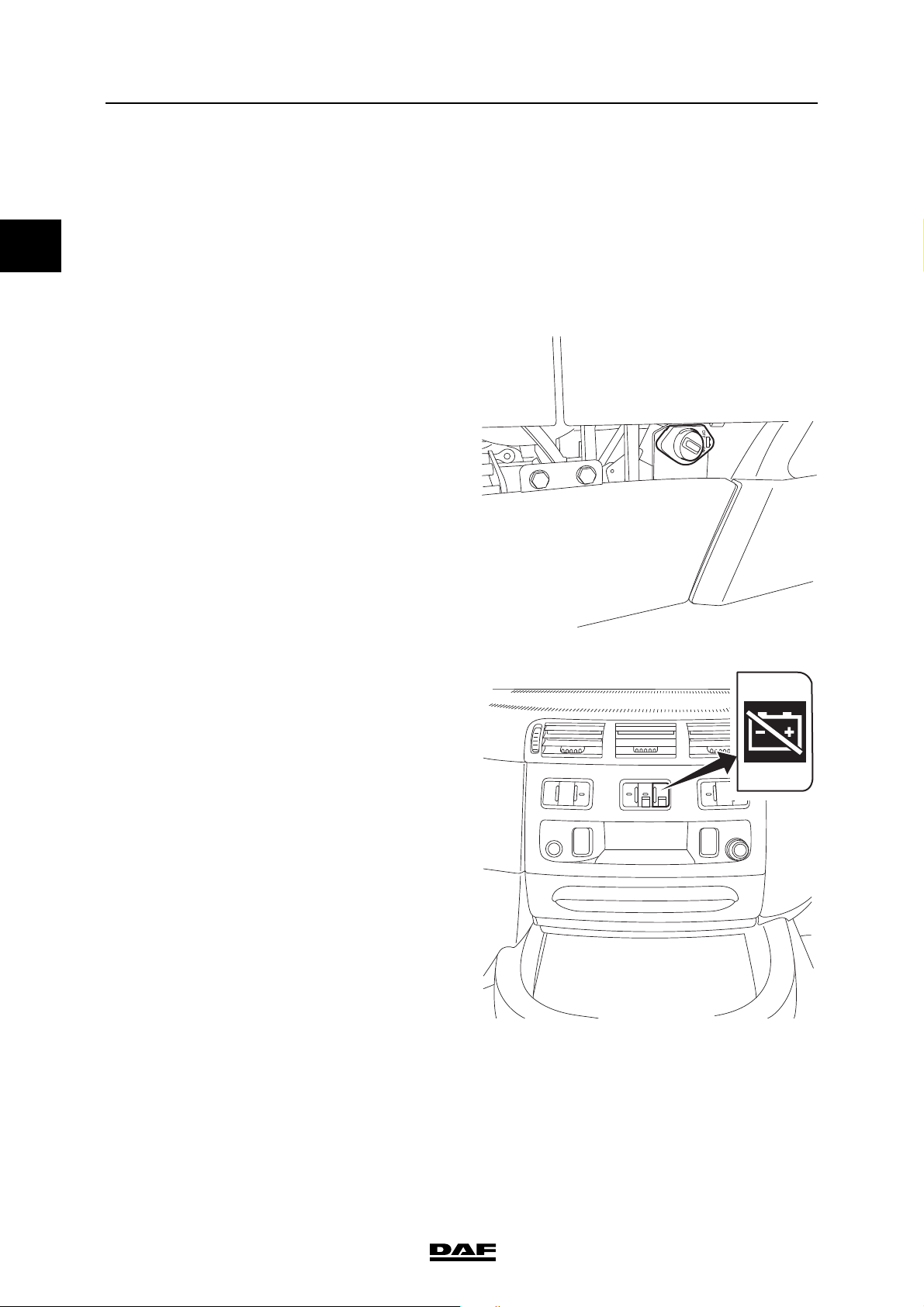
1.2 MAIN SWITCH
If the vehicle is equipped with a main switch, it is
either mechanically or electronically operated,
depending on the vehicle version.
The switch can be used to interrupt the power
supply from the batteries to the vehicle (except
for the tachograph).
Electronic main switch
The electronic main switch does not switch off at
once when it is operated; this happens with a 10second delay. This is to allow the after-running of
various electrical systems on the vehicle.
The electronic main switch (usually located close
to the battery pack).
If the vehicle is equipped with an electronic main
switch, there is also a switch on the centre
console in the cabin.
G001944
E504882
1-2
©
201417
Page 11
EMERGENCY RESPONSE GUIDE
1
G001945
series
Mechanical main switch
Mechanically operated main switches only have a
switch outside the cabin.
Securing the vehicle
©
201417 1-3
Page 12

EMERGENCY RESPONSE GUIDE
1
Securing the vehicle series
1.3 BATTERIES
Location of the batteries
The batteries are located on the left- or right-hand
side of the chassis frame, or at the rear within the
chassis.
Disconnecting the batteries
1. Switch off the ignition.
2. Switch off all electrical consumers.
3. Remove the battery cover.
4. Disconnect the battery clamp from the
negative pole.
5. Disconnect the battery clamp from the
positive pole.
6. Hold the positive and negative cables
together to discharge any power that may be
stored in the capacitors.
7. Secure the cables; make sure that they
cannot come into contact with the terminals.
1-4
©
201417
Page 13
EMERGENCY RESPONSE GUIDE
1
SET
G001309
series
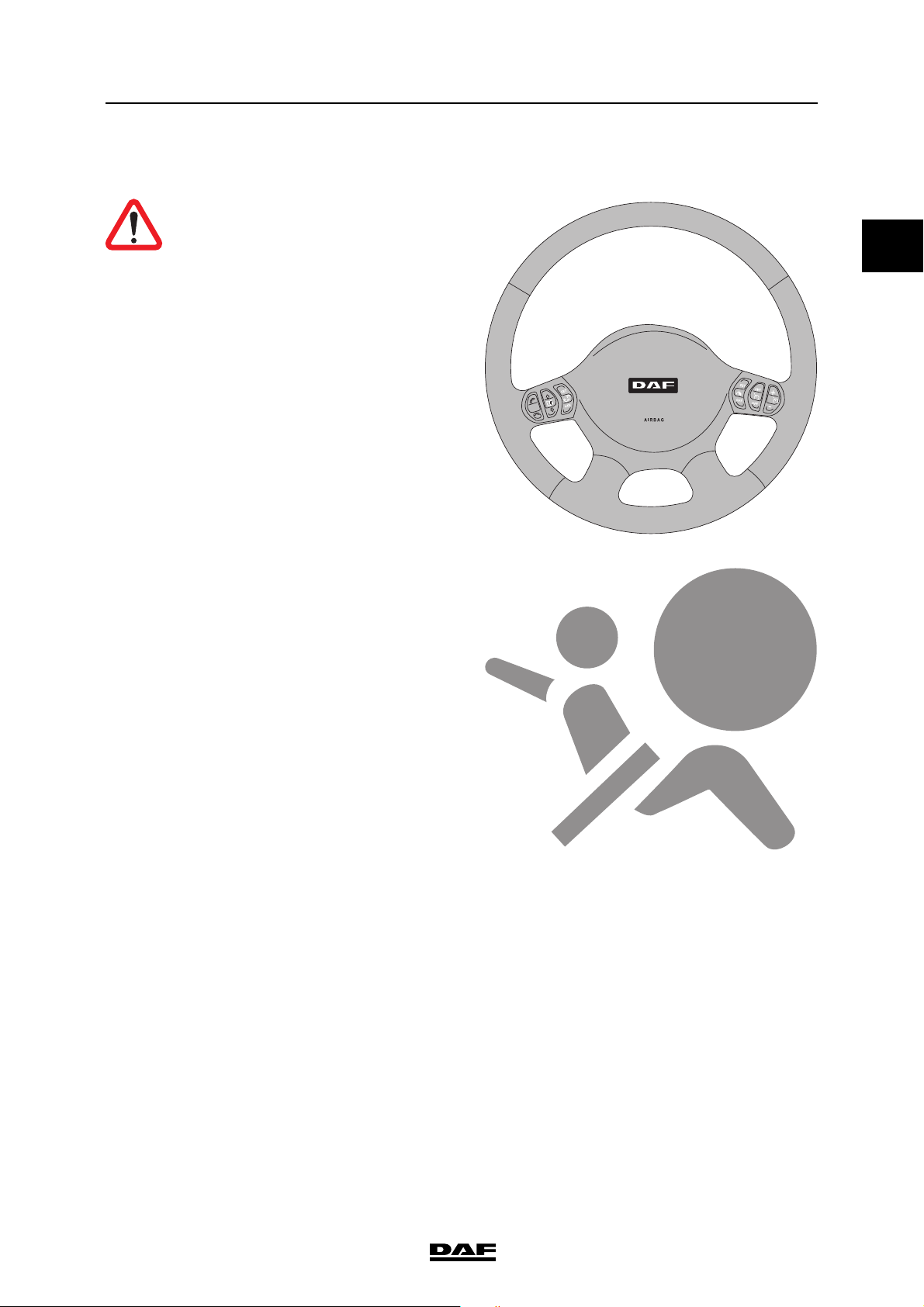
1.4 AIRBAG
WARNING! Airbag modules and
safety belt tensioners are
pyrotechnic systems and contain an
explosive charge.
Securing the vehicle
Vehicles equipped with an airbag and safety belt
tensioner system can be identified by a sticker
with the airbag symbol on the windscreen.
In addition, there is an identification 'AIRBAG'
visible on the steering wheel. A vehicle equipped
with an airbag also has an automatic safety belt
tensioner.
©
201417 1-5
Page 14

EMERGENCY RESPONSE GUIDE
1
G001312
1
Securing the vehicle series
1 Safety belt tensioner
The automatic safety belt tensioner is fitted on the
rear side of the driver's and co-driver's seat.
Safety instructions
- Do not place any objects near undeployed
airbags
- Before any work is carried out on an airbag
system:
1. the ignition must be switched off.
2. the main switch must be turned off.
3. the battery clamp must be removed from
the negative pole.
4. wait at least 30 seconds.
- Never disconnect an electrical connector in
the airbag or safety belt tensioner circuits if
the electronic control unit is energised.
©
201417
1-6
Page 15

EMERGENCY RESPONSE GUIDE
1
series
1.5 FLUIDS
123 6
Securing the vehicle
4
5
123 5
1 Coolant: 48 litres
2 Engine oil: 36 - 46 litres
3 Gearbox oil: 14 litres
4 AdBlue: up to 90 litres
5 Fuel: up to 1500 litres
6 Battery acid
6
4
5
K103769
The capacities and position of the tanks depend
on the vehicle type.
©
201417 1-7
Page 16

EMERGENCY RESPONSE GUIDE
1
Securing the vehicle series
AdBlue
AdBlue is a non-flammable, non-toxic, colourless,
odourless and water-soluble liquid.
AdBlue is a liquid consisting of 32.5% urea and
67.5% water.
AdBlue must meet the specifications according to
DIN 70070.
High temperatures
If AdBlue is heated in the tank to 50°C over a long
period of time, the decomposing AdBlue can
produce ammonia vapours. Ammonia vapours
have a pungent odour. For this reason, avoid
inhaling possible ammonia vapours escaping
when unscrewing the AdBlue filler cap. These
concentrations of ammonia vapours are neither
toxic nor hazardous to health.
Low temperatures
AdBlue freezes at temperatures of approximately
-11°C.
i403182
WARNING!
AdBlue safety instructions
- Avoid direct contact.
- In the event of contact with the
skin, rinse with plenty of water.
- In the event of contact with the
eyes, rinse for at least 15
minutes with plenty of water and
seek medical assistance.
- If swallowed, rinse mouth with
plenty of water; do not induce
vomiting.
- Use in a ventilated area.
Procedure after spillage
- Rinse with plenty of water.
1-8
©
201417
Page 17

EMERGENCY RESPONSE GUIDE
1
V301566
G001961
series
1.6 REGENERATION UNIT
During regeneration the exhaust gases, the
surroundings of the regeneration unit and the
catwalk can reach high temperatures that can
potentially harm bystanders or the surrounding
area.
WARNING! There is a risk of fire or
other hazardous situation if the
temperature can ignite flammable
materials.
Switch off the regeneration unit
Set the switch in the OFF position to stop or
inhibit regeneration.
Securing the vehicle
©
201417 1-9
Page 18

EMERGENCY RESPONSE GUIDE
1
Securing the vehicle series
1-10
©
201417
Page 19

EMERGENCY RESPONSE GUIDE
1
series
2. STABILISING THE VEHICLE
2.1 SEAT ADJUSTMENT
NOTE: Before removing the seat, be
aware of the safety instructions if the
vehicle is equipped with an airbag and
therefore an automatic safety belt
tensioner.
NOTE: The seat can be adjusted if the
vehicle air pressure is at least 7 bar.
Seat settings
1 Backrest angle adjustment.
2 Seat height adjustment.
3 Seat tilt adjustment
4Quick down.
5 Vertical seat damper.
6 Seat length adjustment.
7 Seat cushion length adjustment.
8 Armrest.
9 Safety belt height adjustment.
10 Seat heater.
11 Lumbar support adjustment.
12 Lateral support adjustment.
13 Seat ventilation
14 Shoulder support adjustment.
4. Quick down
Knob down (seat in driving position): the seat drops to its lowest
position.
Knob up (with lowered seat): the
seat rises to the last height adjustment.
3. Seat tilt adjustment
14
Stabilising the vehicle
9
8
13
10
7
5
12
6
4
3 2
1
11
G001947
2. Seat height adjustment
©
201417 2-1
Page 20

EMERGENCY RESPONSE GUIDE
1
M1 M2
STOP
C900268
Stabilising the vehicle series
2.2 AIR SUSPENSION CHASSIS
General
On vehicles equipped with air suspension, a
remote control unit is used to operate the vehicle
height.
The remote control unit is located against the
console of the driver's seat.
NOTE: This control unit can only be
operated when the ignition is switched
on.
NOTE: Unless stated otherwise, the
keys need only be pressed once briefly.
Remote control A
rear of truck selected
automatic setting of normal driving
height
lifting of chassis to pre-set height
as M1, but for a different chassis
height
lifting of selected chassis ends
when the key is released
lowering of selected chassis ends
when the key is released
all adjustments are stopped
2-2
©
201417
Page 21

EMERGENCY RESPONSE GUIDE
1
C900269
M1 M2
STOP
series
Remote control B
Remote control B is used on vehicles on which
the front axle is also equipped with air
suspension.
front of truck selected
rear of truck selected
automatic setting of normal driving
height
lifting of chassis to pre-set height
as M1, but for a different chassis
height
lifting of selected chassis ends
when the key is released
lowering of selected chassis ends
when the key is released
Stabilising the vehicle
all adjustments are stopped
©
201417 2-3
Page 22

EMERGENCY RESPONSE GUIDE
1
M1 M2
STOP
C900592-2
Stabilising the vehicle series
Remote control C
Remote control C is used for vehicles with airsuspended front axle and trailer and for vehicles
with Axle Load Monitoring.
front of truck selected
rear of truck selected
automatic setting of normal driving
height
lifting or lowering truck trailing axle
front of trailer selected
rear of trailer selected
lifting or lowering trailer trailing
axle
lifting of chassis to pre-set height
as M1, but for a different chassis
height
lifting of selected chassis ends
when the key is released
lowering of selected chassis ends
when the key is released
all adjustments are stopped
2-4
©
201417
Page 23

EMERGENCY RESPONSE GUIDE
1
G001946
series
2.3 CABIN SUSPENSION
The cabin can be equipped with full mechanical
or full air suspension.
Lowering the air suspension
If the vehicle is equipped with cabin air
suspension, the cabin can be lowered.
The cabin is lowered by cutting the air hoses.
WARNING! When air hoses are cut,
the hose ends can fly around and
can therefore cause injuries.
WARNING! When the air hoses for
the cabin suspension are cut, the air
supply for steering wheel
adjustment is also taken away.
WARNING! When the cabin is
lowered, the movement may be
uncontrolled.
Rear cabin air suspension
Cut the air hose to the rear cabin air suspension
bellows. The connections are at the bottom of the
bellows.
Stabilising the vehicle
©
201417 2-5
Page 24

EMERGENCY RESPONSE GUIDE
1
G001959
G001960
Stabilising the vehicle series
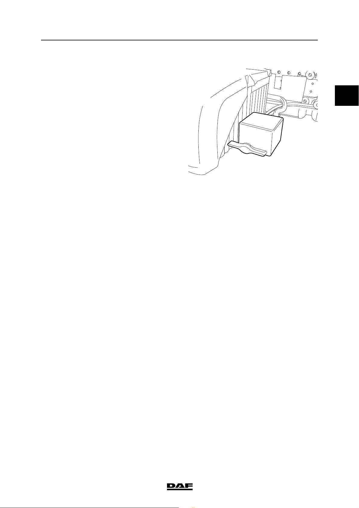
Rear cabin mechanical suspension
Front cabin air suspension
Cut the air hose to the front air suspension
bellows. The air reservoir can be found under the
cabin at the co-driver side.
Front cabin mechanical suspension
The mechanical springs are located at the front
just beside the headlights. They can be reached
by removing the lower grille and if necessary the
headlight panels.
2-6
©
201417
Page 25

EMERGENCY RESPONSE GUIDE
1
G002065
12
3
series
3. RELEASING A TRAPPED DRIVER
3.1 CABIN TYPES
Releasing a trapped driver
1Day Cab
2 Sleeper Cab
3Space Cab
©
201417 3-1
Page 26

EMERGENCY RESPONSE GUIDE
1
Releasing a trapped driver series
3.2 CABIN BRACKET COLLISION ABILITY
The cabin bracket has a built-in safety feature
that enables the cabin to move back 400 mm in
case of a collision. Depending on the severity of
the collision there are two situations.
- The safety feature is used. This means that
the cabin has moved compared to the
chassis with a maximum distance of 400
mm. The cabin is still attached to the chassis.
- The safety feature is used fully before the
collision stopped. As a result the bolt of the
cabin bracket breaks. If this has happened
the cabin is loose from the chassis.
3-2
©
201417
Page 27

EMERGENCY RESPONSE GUIDE
1
G002066
640
2490
2110
2260
1770
650
1600
440
400
390
series
3.3 CABIN DIMENSIONS
The external dimensions from the ground vary
depending on the tyre size, choice of suspension,
load and settings.
Day Cab
Releasing a trapped driver
Sleeper Cab
1600
440
400
390
2200
1050
2260
640
650
L=700
2110
L=2045
G002067
2490
L
120
©
201417 3-3
Page 28

EMERGENCY RESPONSE GUIDE
1
G002069
U
570
640
U=680
U=2020
L=2045
2490
2110
L=700
2260
2200
650
710
2230
440
305
275
280
70
120
L
Releasing a trapped driver series
Space Cab
3-4
©
201417
Page 29

EMERGENCY RESPONSE GUIDE
1
series
3.4 OPENING THE GRILLE
The top section of the front panel can be folded
up. Unlock the front panel by pulling the lever in
the top section of the front panel. When the front
panel is open it is held in the raised position by
two gas struts.
Releasing a trapped driver
G002070
©
201417 3-5
Page 30

EMERGENCY RESPONSE GUIDE
1
Releasing a trapped driver series
3.5 DOORS
1 Hinge
2 Wiring harness
3 Door check
1
2
1
3
G001310
3-6
©
201417
Page 31

EMERGENCY RESPONSE GUIDE
1
G002071
series
3.6 DOOR LOCK
The door lock is installed higher than the door
handle. The position is indicated in the image.
Releasing a trapped driver
©
201417 3-7
Page 32

EMERGENCY RESPONSE GUIDE
1
K101546
Releasing a trapped driver series
3.7 STEERING WHEEL ADJUSTMENT
NOTE: The steering wheel can be
adjusted if the vehicle air pressure
(circuit 4) is at least 7 bar.
G001293
Adjusting
Push up the two-position switch. The steering
column is temporarily unlocked. The height and
angle of the steering wheel can now be adjusted.
Locking
Push down the two-position switch. The steering
column is locked.
NOTE: A slight hissing noise, caused
by the two-position switch, is audible
while the steering wheel is being
adjusted. If the steering column has not
been locked, this switch locks it
automatically after 20 - 30 seconds.
3-8
©
201417
Page 33

EMERGENCY RESPONSE GUIDE
1
G001283-2
A
A
B
E
B
C
F
C
D
E
D
F
series
3.8 CABIN STRUCTURE
Releasing a trapped driver
©
201417 3-9
Page 34

EMERGENCY RESPONSE GUIDE
1
Releasing a trapped driver series
3-10
©
201417
Page 35

EMERGENCY RESPONSE GUIDE
1
series
4. TOWING INFORMATION
4.1 REMOVING THE DRIVE SHAFT
- Make sure that the parking brake is
engaged.
- Loosen the bolts, do not remove them.
- Loosen the bearing.
- Hold the shaft while removing the bolts.
- Fix the bearings to the shaft.
- Fasten the shaft to the chassis.
- Cover the drive shaft joint with a plastic bag.
Towing information
©
201417 4-1
Page 36

EMERGENCY RESPONSE GUIDE
1
R601642
Towing information series
4.2 RELEASING THE PARKING BRAKE
WARNING!
- Never release the park brake on
an incline without precautionary
measures.
Releasing the park brake on an
incline causes the vehicle to move
unintentionally. This can lead to
serious injury and damage to the
vehicle.
1. Place wheel chocks in front of and behind the
wheels.
NOTE: It is not permitted to use a
socket wrench to loosen the
releasing bolt.
2. Turn the releasing bolt anti-clockwise as far
as the stop using a ring spanner.
3. Carry out this operation for each spring
brake cylinder.
NOTE: Place a no brakes warning
label on the steering wheel.
4. Bring the park brake back in operating order
by turning the releasing bolts clockwise as
far as possible and tightening them to a
torque of 45 Nm (75 Nm for the releasing bolt
with control pin). The pressure in the spring
brake cylinder circuit must be at least 6.5 bar.
4-2
©
201417
Page 37

EMERGENCY RESPONSE GUIDE
1
series
5. LIFTING INFORMATION
5.1 LIFTING AT THE FRONT
The front of the truck can be lifted with two towing
eyes. To lift the front of the truck:
1. Install two towing eyes with the axle in
horizontal position.
2. Attach the lifting equipment to the towing
eyes.
3. Carefully lift the truck.
CAUTION: The maximum lifting
weight for the towing eyes is 3000 kg
per towing eye.
NOTE: The two towing eyes can also
be used to fix the front of the truck to a
platform.
Lifting information
©
201417 5-1
Page 38

EMERGENCY RESPONSE GUIDE
1
Lifting information series
5.2 JACK UP AT THE FRONT
Jacking up the air sprung front axle
Place the jack under the special jack up brackets
that are attached to the air sprung front axle.
Jacking up mechanically sprung front axles
Place the jack under the axle.
CAUTION: Do not jack up under the
protection bar at the front of the
vehicle. This is a protection bar
made of sheet metal. If you jack up
the vehicle under the protection bar
it collapses.
5-2
©
201417
Page 39

EMERGENCY RESPONSE GUIDE
1
series
5.3 LIFTING AT THE BACK
There are no special facilities to lift the truck at the
back.
Lifting information
©
201417 5-3
Page 40

EMERGENCY RESPONSE GUIDE
1
Lifting information series
5.4 JACK UP AT THE BACK
There are no special facilities to jack up the truck
at the back. Place the jack under the rear axle.
5-4
©
201417
Page 41

Page 42

English
Printed in the Netherlands DW53288301
 Loading...