

Page 1

6
ΛΦ45/55 series
STRUCTURE
Structure
TECHNICAL DATA
DIAGNOSTICS
BRAKE DIAGRAMS FOR THE FULLY PNEUMATIC BRAKE SYSTEM
OPERATION OF BRAKE COMPONENTS
BRAKE SYSTEM AND COMPONENTS
BRAKING PERFORMANCE AND BRAKE EQUALISATION
0
1
2
3
4
5
©
200436 DW23259602
Page 2

Page 3

6
TECHNICAL DATA
ΛΦ45/55 series
0 Technical data
CONTENTS
Page Date
1. BRAKE SYSTEM AND COMPONENTS. . . . . . . . . . . . . . . . . . . . . . . . . . . . . . . 1-1 . . . . . 200436
1.1 General . . . . . . . . . . . . . . . . . . . . . . . . . . . . . . . . . . . . . . . . . . . . . . . . . . . 1-1 . . . . . 200436
1.2 Tightening torques. . . . . . . . . . . . . . . . . . . . . . . . . . . . . . . . . . . . . . . . . . . 1-12 . . . . 200436
1.3 Lubricants . . . . . . . . . . . . . . . . . . . . . . . . . . . . . . . . . . . . . . . . . . . . . . . . 1-16 . . . . 200436
Contents
0
©
200436 1
Page 4

TECHNICAL DATA
6
0
Contents
ΛΦ45/55 series
2
©
200436
Page 5

6
TECHNICAL DATA
ΛΦ45/55 series
1. BRAKE SYSTEM AND COMPONENTS
1.1 GENERAL
Coding of components
All components have been provided with number
codes.
Structure of the code
First digit
Often used:
1 Energy supply (pressure)
2 Energy discharge (outgoing command)
3Bleed
4 Control connection (incoming command)
Little used:
0 Suction connection
5Free
6Free
7 Anti-freeze connection
8 Lubricating oil connection
9 Coolant connection
Where one connection performs several
functions, additional 1
These are separated by a hyphen.
st
digits will be allocated.
Brake system and components
0
Second digit
If there are several connections with the same
function, a 2
after the 1
Application example: empty/load relay valve
Meaning:
1 Air compressor energy supply
2 Energy discharge (command) to the next
41 Control connection (incoming)
42 Second control connection (incoming)
COMPRESSOR
Knorr model
Type: LK3839
Version: 1-cylinder, liquid-cooled
nd
digit will be added immediately
st
one.
component
©
200436 1-1
Page 6

TECHNICAL DATA
6
0
Brake system and components
AIR SUPPLY UNIT
Front axle, leaf-sprung
A
D
F
C
1
12
A Air dryer/pressure regulator (unit)
B 4-circuit protection valve (unit)
C Filter/drying grid
D Pressure regulator
E Blow-off valve
F Pneumatic time switch for regeneration
G Heating element
H Pressure relief valve with bypass, circuit 1
J Pressure relief valve with bypass, circuit 2
K Pressure limiting valve, circuit 3
L Pressure relief valve, circuit 3
M Flowback valve, circuit 3
N Pressure relief valve with bypass, circuit 4
P Pressure sensors
E
0
G
6.1
3
6.2
21
B
2123 3 23 25
1
NJK
24
26
22
ΛΦ45/55 series
MH
L
P
P
P
U
U
R600702
6.2
6.3
6.4
6.5
6.6
6.7
Cut-out pressure of pressure regulator 10.0 ≥ 0.2 bar
Cut-in pressure of pressure regulator 1.2 ≥ 0.2 bar under cut-out pressure
Supply pressure in circuit 1, connection 21 max. 10 bar
Supply pressure in circuit 2, connection 22 max. 10 bar
Supply pressure in circuit 3, connection 23 8.5 - 0.4 bar
Supply pressure in circuit 3, connection 25 8.5 - 0.6 bar
Supply pressure in circuit 4, connection 24 max. 10 bar
Supply pressure in circuit 4, connection 26 max. 10 bar
Opening pressure of circuits 1, 2 and 4 8.5 bar
Opening pressure of circuit 3 7.0 bar
Closing pressure of circuits 1, 2 and 4 7 bar
Closing pressure of circuit 3 5.5 bar
Cut-in temperature of heating element 7C
Cut-out temperature of heating element 29C
Circuit 1 activation pressure for flowback function
of circuit 3 < 4.5 bar
1-2
©
200436
Page 7

6
TECHNICAL DATA
ΛΦ45/55 series
Pressure sensor reading, circuits 1 and 2
(connections 6.2 - 6.7 in the diagram above)
FOOT BRAKE VALVE
Ua(V)
5V
4V
3V
2V
1V
0V
Brake system and components
P21
bar
P22
10
9
8
7
6
5
4
3
2
1
0
123456789101112
Pressure difference between circuits 1 and 2 (between 0 and 3 bar) 0.3 ≥ 0.15 bar
P21-P22 = 0,3
21
22
– 0,15
0
12024 6810
P
(bar)
21.22
R600701
bar
C (cm)
R600594
Pressure reduction in circuits 1 and 2 from 10 to
8 bar
Connection 11 circuit 1 supply
Connection 12 circuit 2 supply
Connection 21 circuit 1 braking pressure
Connection 22 circuit 2 braking pressure
©
200436 1-3
Page 8

TECHNICAL DATA
6
0
Brake system and components
LOAD-DEPENDENT CONTROL VALVE,
LEAF SPRING
Characteristic
LOAD-DEPENDENT CONTROL VALVE,
AIR SUSPENSION
Characteristic
0.6
10
9
p2 [bar]
8
7
6
5
4
3
2
1
–0.2
ΛΦ45/55 series
1:1
23 45678 910
10
p4 [bar]
R600704
p41
= 4.65 bar
p42
p41
= 3 bar
p42
p41
= 0.3 bar
p42
R600705
LOW-PRESSURE SWITCH
Cut-out pressure: 5.2 ≥ 0.2 bar
1-4
©
200436
Page 9

6
TECHNICAL DATA
ΛΦ45/55 series
RELAY VALVE
Fitted with internal filter and silencer
EMPTY/LOAD RELAY VALVE
10
Brake system and components
9
8
P2 (bar)
7
6
5
4
3
2
1
10 23456789
0
P4 (bar)
R 600363
9
P2(bar)
8
7
6
5
4
3
2
1
0
Maximum reduction ratio 1 : 2.7
Actuating pressure 0.25 bar
Fitted with internal filter and silencer
P
= P
42
41
1:2.7
P
= 0
42
1
2345678910
+
0,1
0,25
P41(bar)
R600330
©
200436 1-5
Page 10

TECHNICAL DATA
6
0
Brake system and components
ABS VALVE
Resistance of magnet coil 15 ≥ 5 ohm at 25C
Electrical connections
1. Bleed magnet coil
2. Earth
3. Aerate magnet coil
21
3
ΛΦ45/55 series
1
2
3
123
ASR solenoid valve
1. Supply
2. Port, two-way valve
3. Bleed
TRAILER VEHICLE CONTROL VALVE
Knorr model
Type: AC 597BA
Advance
Input pressure 3 bar
Output pressure 3.2 bar
(equals 0.2 bar advance = factory setting)
R600370
1
2
3
R600484
1-6
©
200436
Page 11

6
TECHNICAL DATA
ΛΦ45/55 series
Advance adjustment
Adjusting screw (Allen type, 6 mm)
Clockwise increases the advance
Anti-clockwise decreases the advance
Knorr model
Type: AC 597C
Advance
Input pressure 3 bar
Output pressure 3.5 bar
(equals 0.5 bar advance = factory setting)
Advance adjustment
Adjusting screw (Allen type, 6 mm)
Clockwise increases the advance
Anti-clockwise decreases the advance
PARKING BRAKE VALVE WITH TRAILER
VEHICLE CONNECTION
Brake system and components
0
Wabco model
Type: 961 723 134 0
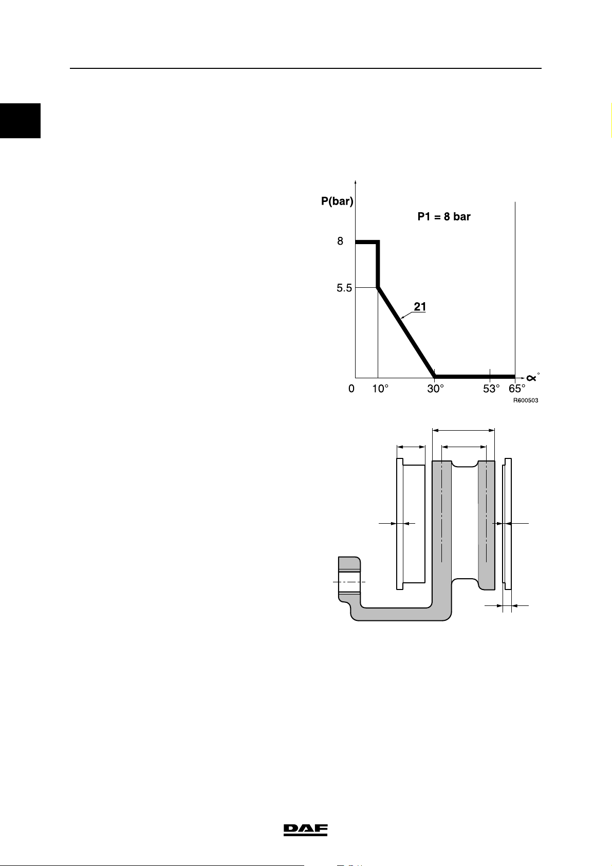
Max. output pressure in driving position approx. 8 bar
©
200436 1-7
Page 12
TECHNICAL DATA
6
0
Brake system and components
PARKING BRAKE VALVE WITHOUT TRAILER
VEHICLE CONNECTION
Wabco model
Type: 961 723 036 0
Max. output pressure in driving position approx. 8 bar
ΛΦ45/55 series
BRAKE PADS
A
C
Knorr model
Maximum brake block thickness (C) 30 mm
Maximum lining thickness (E) 2 mm (at the thinnest point)
Minimum brake block thickness (F) 11 mm (at the thinnest point) with 9mm rear plate
thickness (D)
Replacing: all brake pads at the same time for each axle, and
with the specified lining only.
B
ED
F
R600489
1-8
©
200436
Page 13
6
TECHNICAL DATA
ΛΦ45/55 series
Wabco PAN 17 version:
Maximum brake block thickness (C) 26 mm
Maximum lining thickness (E) 2 mm (at the thinnest point)
Minimum brake block thickness (F) 9 mm (at the thinnest point) with 7mm rear plate
thickness (D)
Replacing: all brake pads at the same time for each axle, and
with the specified lining only.
Wabco PAN 19-1+ and PAN 19-2 versions:
Maximum brake block thickness (C) 30 mm
Maximum lining thickness (E) 2 mm (at the thinnest point)
Minimum brake block thickness (F) 11 mm (at the thinnest point) with 9mm rear plate
thickness (D)
Replacing: all brake pads at the same time for each axle, and
with the specified lining only.
BRAKE DISC
Brake system and components
A
C
B
0
R600489
Knorr model
Maximum brake disc thickness (A) 45 mm
Minimum brake disc thickness (B) 37 mm (rejection dimension, disc must be
replaced)
Minimum thickness, turning dimension 40 mm
Note:
If it is established during brake pad replacement
that the brake thickness is less than or equal to
39 mm, the brake disc must also be replaced.
ED
F
©
200436 1-9
Page 14

TECHNICAL DATA
6
0
Brake system and components
The following signs of wear are permissible:
A1 Crazy cracking.
B1 Cracks running to the centre up to 1.5 mm
wide and deep, max. 0.75 x friction
surface width (a).
C1 Unevenness in the disc surface up to
1.5 mm.
Not permissible:
D1 Through-going cracks.
Wabco model
PAN 17 version:
Maximum brake disc thickness (A) 34 mm
Minimum brake disc thickness (B) 28 mm (rejection dimension, disc must be
Minimum thickness, turning dimension 30 mm
A
B
1
D
C
1
replaced)
a
ΛΦ45/55 series
1
max. 0,75 x a
max. 1,5 mm
1
R600471
The following signs of wear are permissible:
A1 Crazy cracking.
B1 Cracks running to the centre up to 1.5 mm
wide and deep,
max. 0.75 x friction surface width (a).
C1 Unevenness in the disc surface up to
1.5 mm.
Not permissible:
D1 Through-going cracks.
Brake disc wobble 0.15 mm
A Measuring distance is 35 mm
A
R600508
1-10
©
200436
Page 15

6
TECHNICAL DATA
ΛΦ45/55 series
PAN 19-1+ and PAN 19-2 versions:
Maximum brake disc thickness (A) 45 mm
Minimum brake disc thickness (B) 38 mm (rejection dimension, disc must be
replaced)
Minimum thickness, turning dimension 40 mm
The following signs of wear are permissible:
A1 Crazy cracking.
B1 Cracks running to the centre up to 1.5 mm
wide and deep,
max. 0.75 x friction surface width (a).
C1 Unevenness in the disc surface up to
1.5 mm.
Not permissible:
D1 Through-going cracks.
Brake disc wobble 0.15 mm
A Measuring distance is 35 mm
BRAKE CALLIPER
Knorr model
Brake system and components
0
A
R600708
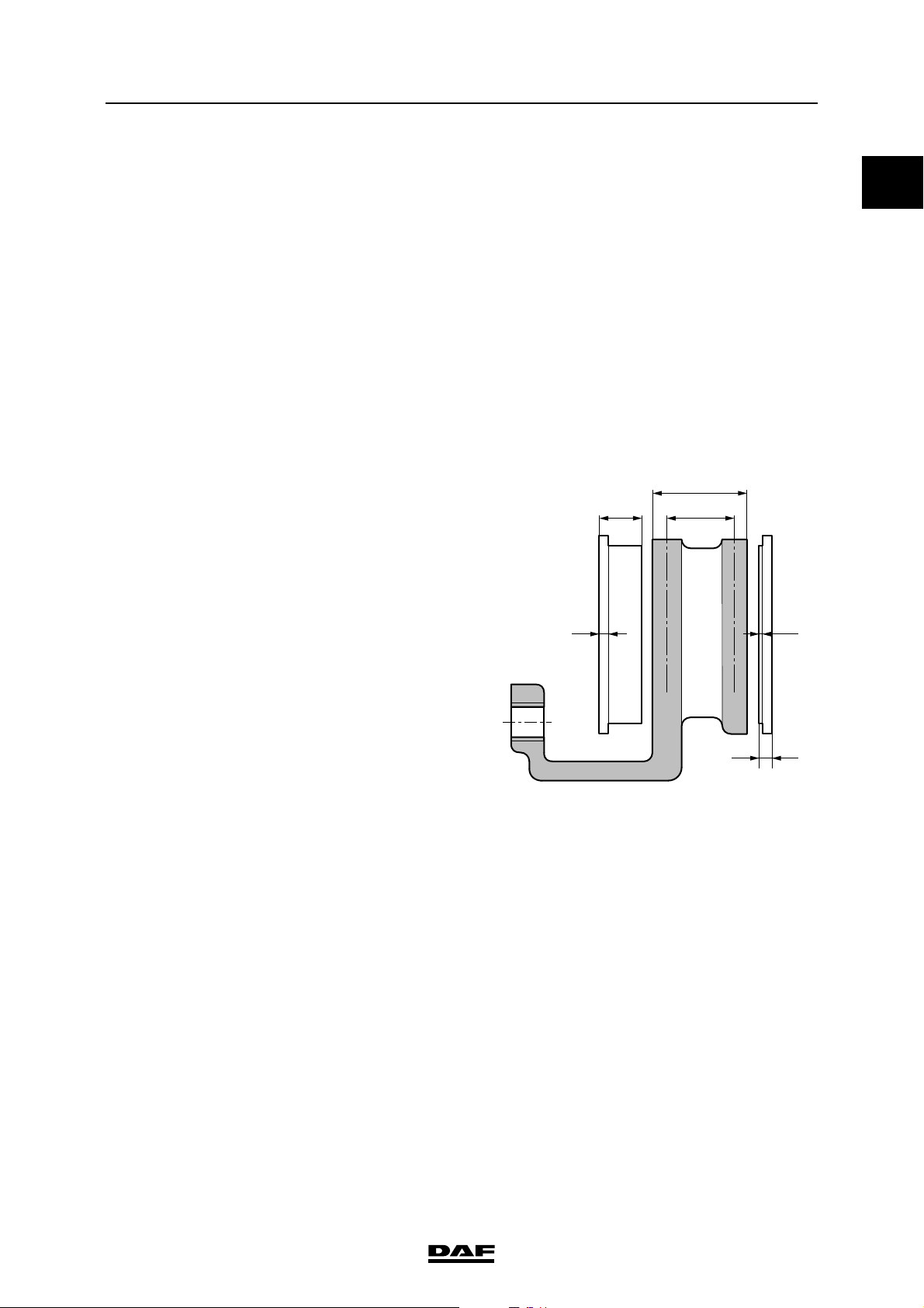
Brake calliper play in axial direction (direction A) 0.6 - 1.0 mm
Brake calliper play on guide bushes ("Y" - "X") max. 2.0 mm
Play between brake calliper carrier and brake
pads ("Y" - "X" direction) 0.3 - 0.9 mm
Wabco model
Play between brake pad/brake disc:
Manually adjustable brake pad/brake disc play
after fitting brake pads: 0.7 mm
Y - X
R600712
©
200436 1-11
Page 16

TECHNICAL DATA
6
0
Brake system and components
1.2 TIGHTENING TORQUES
The tightening torques stated in this section are
different from the standard tightening torques
stated in the overview of the standard tightening
torques. The other threaded connections not
specified must therefore be tightened to the
torque stated in the overview of standard
tightening torques.
When attachment bolts and nuts are replaced, it
is important that - unless stated otherwise - these
bolts and nuts are of exactly the same length and
property class as those removed.
QUICK-RELEASE COUPLING
Parker 20 - 30 Nm
SPRING BRAKE CYLINDER
Attachment nuts 195 Nm
Release bolt 70 Nm
Clamping strip attachment nut 40 Nm
BRAKE CYLINDER
Attachment nuts 195 Nm
ΛΦ45/55 series
BRAKE CALLIPER - BRAKE CARRIER, Knorr
model
Sliding sleeve Allen screws (SB7000) 285 Nm
Sliding sleeve Allen screws (SN7000) 180 Nm + 90
Pressure tool, guide bush bellows 8 Nm
Rubber bearing bush pressure tool (only
SN7000) 8 - 45 Nm
(1) Always use new bolts, provided with locking compound.
New bolts are supplied with locking compound already
applied.
(1)
(1)
1-12
R600744
©
200436
Page 17
6
TECHNICAL DATA
ΛΦ45/55 series
Brake calliper attachment bolts, front axle 440 Nm
(1) From production date 2003-37 there is one fitted bolt and
flange bolts are also fitted.
The fitted bolt must be fitted at the position marked by a
small hole.
(2) In the case of versions with Knorr disc brakes, the
attachment of the brake calliper against the stub axle
changed starting from production week 2002-25. Five
bolts are now used instead of six bolts. There is still a hole
th
for the 6
the stub axle.
bolt on the brake carrier, but there is no hole on
Brake calliper attachment bolts, rear axle 440 Nm
(1) From production date 2003-37 there is one fitted bolt and
flange bolts are also fitted.
- In the case of the 11.26 rear axle, the fitted bolt must
be fitted at the position marked "X".
- In the case of the 11.32 rear axle, the fitted bolt must
be fitted at the position marked by a small hole.
(1) (2)
(1)
Brake system and components
0
BRAKE CALLIPER - BRAKE CARRIER,
Wabco model
Locking bracket bolt (PAN 17) 20 Nm
Locking bracket bolt (PAN 19-1+ and PAN 19-2) 37 Nm
Guide bush Allen screws (PAN 17) 340 Nm
Guide bush Allen screws (PAN 19-1+ and
PAN 19-2) 300 Nm
Brake calliper attachment bolts against stub axle
or back plate (PAN 17) 213 Nm
Brake calliper attachment bolts against stub axle
or back plate (PAN 19-1+ and PAN 19-2) 470 Nm
X
R600791
©
200436 1-13
Page 18

TECHNICAL DATA
6
0
Brake system and components
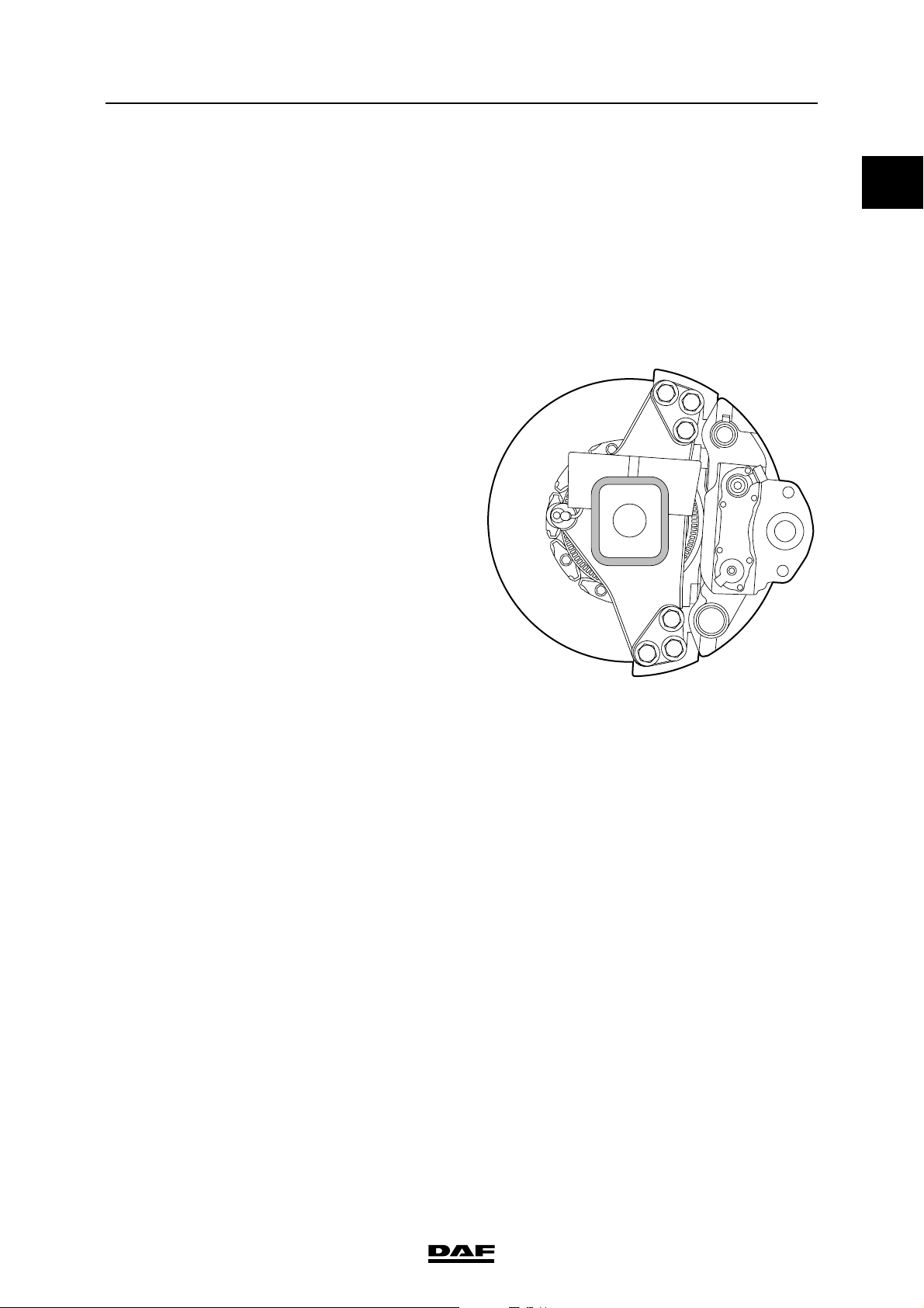
Tightening sequence of brake calliper
attachment bolts, Wabco model
Tightening sequence of brake calliper attachment
bolts:
6 23 1 54
BRAKE DISC
Knorr model
Locking plate attachment bolts 32 Nm
Wabco model
PAN 17 version
Brake disc attachment bolts on front axle 115 ≥ 7 Nm
Brake disc attachment bolts on rear axle 130 Nm
ΛΦ45/55 series
R600520
PAN 19-1+ and PAN 19-2 versions
Brake disc attachment bolts on front axle 210 ≥ 21 Nm
Brake disc attachment bolts on rear axle 193 Nm
1-14
©
200436
Page 19

6
TECHNICAL DATA
ΛΦ45/55 series
Tightening sequence of brake disc on
F36 axle
Tightening sequence of brake disc on
F48 axle
Brake system and components
0
3
9
5
1
11
8
7
12
2
6
10
4
R600732
3
16
13
9
5
1
11
8
15
4
7
12
2
6
10
14
R600731
©
200436 1-15
Page 20

TECHNICAL DATA
6
0
Brake system and components
1.3 LUBRICANTS
BRAKE CALLIPER, KNORR MODEL
SB7000 version
18
ΛΦ45/55 series
20
21
19
17
1
3
4
6
5
8
10
9
12
7
16
15
14
11
13
2
22
1-16
R600541
©
200436
Page 21

6
TECHNICAL DATA
ΛΦ45/55 series
Renolit HLT2 (white) for parts 6, 7, 8, the
adjusters (not shown), the brake cylinder lever
and the flange surface for attachment of the
brake cylinder 1448907
Syntheso GL EP1 (green), for parts 3, 5 1448908
Brake system and components
0
©
200436 1-17
Page 22

TECHNICAL DATA
6
0
Brake system and components
SN7000 version
18
ΛΦ45/55 series
20
21
19
5
17
1
6a
6
3
7
4
8
11
10
2
Renolit HLT2 (white) for parts 3, 6, 7, 8, the
adjusters (not shown), the brake cylinder lever
and the flange surface for attachment of the
brake cylinder 1448907
22
16
23
15
14
R600698
BRAKE CALLIPER, WABCO MODEL
Renolit G-BRF 2
1-18
©
200436
Page 23

6
DIAGNOSTICS
ΛΦ45/55 series
1 Diagnostics
CONTENTS
Page Date
1. DISC BRAKE CONSTRUCTION. . . . . . . . . . . . . . . . . . . . . . . . . . . . . . . . . . . . . 1-1 . . . . . 200436
1.1 Fault-finding table . . . . . . . . . . . . . . . . . . . . . . . . . . . . . . . . . . . . . . . . . . . 1-1 . . . . . 200436
Contents
1
©
200436 1
Page 24

DIAGNOSTICS
6
1
Contents
ΛΦ45/55 series
2
©
200436
Page 25

6
DIAGNOSTICS
ΛΦ45/55 series
Disc brake construction
1. DISC BRAKE CONSTRUCTION
1.1 FAULT-FINDING TABLE
SYMPTOM: SQUEALING/NOISE DURING BRAKING
Possible cause Remedy
Worn brake pads Check brake pads and brake disc thickness
Loose parts Check disc brake construction
Wear/damage to hub bearing Check hub bearing play
Wear to internal parts of disc brake construction Check internal parts
Incorrect vehicle combination Check vehicle combination
Incorrect front axle / rear axle brake pressure
balance
SYMPTOM: IRREGULAR BRAKE PAD WEAR
Possible cause Remedy
Check front axle / rear axle balance
1
Fouled/corroded guide bushes Check the guide bushes
Dirt accumulation between moving parts of the disc
brake construction
Moisture and dirt on internal mechanical parts Check and clean the brake calliper seals
Brake pad stuck in the brake calliper Incorrect play
between brake pads and brake carrier
SYMPTOM: VEHICLE PULLS TO ONE SIDE DURING BRAKING
Possible cause Remedy
Difference in tyre pressure Check / correct tyre pressure
Difference in tyre size Check tyres
Different brake cylinder diameters Check brake cylinder diameters
Broken springs in brake cylinders Check brake cylinders
Leaking brake cylinders Check brake cylinders
Fouled brake cylinders Check the brake cylinders for fouling
Excessive stub axle bearing play Check stub axle bearing play
Excessive steering ball joint play Check steering ball joint play
Clean the disc brake construction
Check the play between brake pads and brake
carrier
Excessive shackle pin play Check shackle pin play
Incorrect vehicle combination Check vehicle combination
Incorrect ABS operation Check ABS operation
Brake pad stuck in the brake calliper Incorrect play
between brake pads and brake carrier
©
200436 1-1
Check the play between brake pads and brake
carrier
Page 26

DIAGNOSTICS
6
1
Disc brake construction
SYMPTOM: POOR BRAKING DECELERATION
Possible cause Remedy
Overload due to excessive loading Check vehicle loading condition
System pressure too low Check pressure regulator setting
Air leakage in the brake system Check the brake system for leakage
Insufficient braking power / poor condition of trailer
vehicle brake system
Pinched brake lines Check / replace brake lines
Brake cylinder stroke too large Check automatic slack adjuster
Frozen brake system Check brake system
Brake components affected by road salt Check the brake components for fouling.
Fouled brake cylinders Check the brake cylinders for fouling
Incorrect brake cylinder diameter Check brake cylinders
Incorrect operation / setting of load sensing valve Check operation / setting of load sensing valve
Incorrect vehicle combination Check vehicle combination
Check trailer vehicle
ΛΦ45/55 series
Incorrect ABS operation Check ABS operation
Brake pad stuck in the brake calliper Incorrect play
between brake pads and brake carrier
SYMPTOM: VIBRATIONS DURING BRAKING
Possible cause Remedy
Incorrect wheel tightening procedure Tighten wheels according to tightening procedure
Non-standard wheels fitted Fit only standard wheels
Overload due to excessive loading Check vehicle loading condition
Incorrect front axle / rear axle brake pressure
balance
Wrong brake pad quality Check brake pads
Dirt/deposits on brake disc Check/clean brake disc
Loose parts Check disc brake construction
Wear/damage to hub bearing Check hub bearing play
Damage to disc brake Check thickness and condition of brake disc
Play in cab suspension Check cab suspension
Check the play between brake pads and brake
carrier
Check front axle / rear axle balance
Incorrect vehicle combination Check vehicle combination
1-2
©
200436
Page 27

6
DIAGNOSTICS
ΛΦ45/55 series
SYMPTOM: LOCKING OF THE BRAKES
Possible cause Remedy
Incorrect setting of load sensing valve Check setting of load sensing valve
Thermal overload of non-locking axle brake pads Check non-locking axle brake pads
Incorrect system pressure due to incorrect
pressure regulator setting
Defective trailer vehicle brake system Check trailer vehicle brake system
Incorrect vehicle combination Check vehicle combination
Incorrect ABS operation Check ABS operation
Tyres have too little tread Check tread
Brake pad stuck in the brake calliper Incorrect play
between brake pads and brake carrier
SYMPTOM: INCREASED BRAKE PAD WEAR
Possible cause Remedy
Check pressure regulator setting
Check the play between brake pads and brake
carrier
Disc brake construction
1
Overload due to excessive loading Check vehicle loading condition
Incorrect setting of load sensing valve Check setting of load sensing valve
Incorrect vehicle combination or front axle/rear
axle balance
Defective trailer vehicle brake system Check trailer vehicle brake system
Air pressure in spring brake cylinders too low
during driving, dragging brakes
Dragging brakes because parking brake is not
released
Dirt under foot brake valve / floor mat too high Check for free movement of foot brake valve
Dirty / blocked brake valve bleeders Check valve bleeders
Brake pad stuck in the brake calliper Incorrect play
between brake pads and brake carrier
Incorrect setting of the trailer vehicle control valve/
trailer vehicle reaction valve
Check vehicle combination or front axle/rear axle
balance
Check air pressure in spring brake cylinders with
the parking brake valve in the driving position
Check release of parking brake
Check the play between brake pads and brake
carrier
Check setting of the trailer vehicle control valve/
trailer vehicle reaction valve
©
200436 1-3
Page 28
DIAGNOSTICS
6
1
Disc brake construction
SYMPTOM: DRAGGING BRAKES
Possible cause Remedy
Leaking foot brake valve to circuit 1 and/or 2 Check the foot brake valve for leaks
Dirt/deposits in brake calliper of disc brake Check freedom of movement of brake calliper
Brake pads turned back too tightly Check minimum brake pad play
Air pressure in spring brake cylinders too low
during driving
Output supply pressure from trailer vehicle control
valve to trailer/semi-trailer too low
Dirt under foot brake valve / floor mat too high Check for free movement of foot brake valve
Dirty / blocked brake valve bleeders Check valve bleeders
Brake pad stuck in the brake calliper Incorrect play
between brake pads and brake carrier
Check output pressure of the double-check relay
valve
Check four-circuit safety valve for dirt
Check output pressure of the parking brake valve
in the driving position
Check output supply pressure of the trailer vehicle
control valve
Check the play between brake pads and brake
carrier
ΛΦ45/55 series
1-4
©
200436
Page 29

BRAKE DIAGRAMS FOR THE FULLY PNEUMATIC BRAKE SYSTEM
6
ΛΦ45/55 series
2 Brake diagrams for the fully pneumatic br ake system
CONTENTS
Page Date
1. GENERAL . . . . . . . . . . . . . . . . . . . . . . . . . . . . . . . . . . . . . . . . . . . . . . . . . . . . . . 1-1 . . . . . 200436
1.1 Brake diagrams . . . . . . . . . . . . . . . . . . . . . . . . . . . . . . . . . . . . . . . . . . . . . 1-1 . . . . . 200436
2. BRAKE DIAGRAMS FOR THE FULLY PNEUMATIC BRAKE SYSTEM . . . . . 2-1 . . . . . 200436
2.1 Legend, brake diagrams for the fully pneumatic brake system . . . . . . . . . 2-1 . . . . . 200436
2.2 Brake diagrams for the fully pneumatic brake system . . . . . . . . . . . . . . . . 2-2 . . . . . 200436
Contents
2
©
200436 1
Page 30

BRAKE DIAGRAMS FOR THE FULLY PNEUMATIC BRAKE SYSTEM
6
2
Contents
ΛΦ45/55 series
2
©
200436
Page 31

BRAKE DIAGRAMS FOR THE FULLY PNEUMATIC BRAKE SYSTEM
6
ΛΦ45/55 series
1. GENERAL
1.1 BRAKE DIAGRAMS
Due to the large number of variants for each
vehicle type and for each country, it is impractical
to list all these variants.
Thus a selection has been shown which can form
the basis for other variants.
General
2
©
200436 1-1
Page 32

BRAKE DIAGRAMS FOR THE FULLY PNEUMATIC BRAKE SYSTEM
6
2
General
ΛΦ45/55 series
1-2
©
200436
Page 33

BRAKE DIAGRAMS FOR THE FULLY PNEUMATIC BRAKE SYSTEM
6
ΛΦ45/55 series
Brake diagrams for the fully pneumatic brake system
2. BRAKE DIAGRAMS FOR THE FULLY PNEUMATIC BRAKE SYSTEM
2.1 LEGEND, BRAKE DIAGRAMS FOR THE FULLY PNEUMATIC BRAKE
SYSTEM
Component no. Description
1 Compressor
4 Air supply unit
A = ECAS connecting point
B = Auxiliary consumer connecting point
7 Air reservoir
12 Coupling head
13 Quick-release valve
14 Brake chamber
16 Foot brake valve
19 Parking brake low-pressure switch
2
21 Load sensing valve, leaf suspension
22 Load sensing valve, air suspension
33 Relay valve
35 Empty/load relay valve
46 Trailer control valve
49 Spring brake cylinder
52 Parking brake valve with trailer control
53 Parking brake valve without trailer control
62 Emergency filling/test connection
B237 ASR valve
B256 ABS valve, front axle
B257 ABS valve, front axle
B258 ABS valve, rear axle
B259 ABS valve, rear axle
©
200436 2-1
Page 34

BRAKE DIAGRAMS FOR THE FULLY PNEUMATIC BRAKE SYSTEM
6
2
Brake diagrams for the fully pneumatic brake system
ΛΦ45/55 series
2.2 BRAKE DIAGRAMS FOR THE FULLY PNEUMATIC BRAKE SYSTEM
Brake diagram number Vehicle version
R600557 4x2 vehicle, FA configuration, LF45
- Without trailer connection
- With leaf-sprung rear axle
- With ABS, without ASR
R600558 4x2 vehicle, FA configuration, LF45
- With trailer connection
- With air-sprung rear axle
- With ABS, without ASR
R600563 4x2 vehicle, FA configuration, LF45
- Without trailer connection
- With leaf-sprung rear axle
- With ABS, with ASR
R600560 4x2 vehicle, FA configuration, LF55
- Without trailer connection
- With leaf-sprung rear axle
- With ABS, without ASR
R600734 4x2 vehicle, FA configuration, LF55
4x2 vehicle, FT configuration, LF55
- With trailer connection
- With air-sprung rear axle
- With ABS, without ASR
R600564 4x2 vehicle, FA configuration, LF55
- Without trailer connection
- With leaf-sprung rear axle
- With ABS, with ASR
R600733 6x2 vehicle, FAN configuration, LF55
- With air-sprung rear axle
- With ABS, without ASR
2-2
©
200436
Page 35

BRAKE DIAGRAMS FOR THE FULLY PNEUMATIC BRAKE SYSTEM
6
ΛΦ45/55 series
BRAKE DIAGRAM R600557
4x2 FA
16
21
22
11
12
7
7
Brake diagrams for the fully pneumatic brake system
62
2
53
1/4
1
21
2
33
2
4
1
12
B258
19
1
21
22
11
49
12
12
B256
62
11
49
12
R600557
2
62
14
11
11
14
62
B
A
25
22
23
21
pp
uu
11
29
23
12
24 26
4
1
62
7
2
1
0
©
200436 2-3
Page 36

BRAKE DIAGRAMS FOR THE FULLY PNEUMATIC BRAKE SYSTEM
6
2
Brake diagrams for the fully pneumatic brake system
BRAKE DIAGRAM R600558
4x2 FA
62
2
1/4
16
21
22
11
12
7
7
53
1
21
1
22
2
33
2
4
1
22
62
ΛΦ45/55 series
R600558
12
B258
19
11
49
12
7
12
B256
62
11
49
12
12
11
4341
42
22
124612
11
14
B
A
25
22
23
21
pp
uu
11
29
23
12
24 26
4
1
62
11
14
62
7
2
1
0
2-4
©
200436
Page 37

BRAKE DIAGRAMS FOR THE FULLY PNEUMATIC BRAKE SYSTEM
6
ΛΦ45/55 series
BRAKE DIAGRAM R600560
4x2 FA
16
21
22
11
12
7
7
Brake diagrams for the fully pneumatic brake system
R600560
62
2
53
1/4
1
21
2
33
2
4
1
1
21
22
19
49
12
B258
11
12
62
11
49
12
2
2
1
41 42
35
14
62
1
2
11
B257
62
2
1
11
14
B256
62
B
A
25
22
23
21
pp
uu
11
29
23
12
24 26
4
1
62
7
2
1
0
©
200436 2-5
Page 38

BRAKE DIAGRAMS FOR THE FULLY PNEUMATIC BRAKE SYSTEM
6
2
Brake diagrams for the fully pneumatic brake system
BRAKE DIAGRAM R600734
4x2 FT
4x2 FA
62
2
1/4
16
21
22
11
12
7
7
53
1
21
1
22
2
33
2
4
1
22
62
7
19
49
12
B258
11
12
ΛΦ45/55 series
R600734
62
11
49
12
12
11
4341
42
22
124612
2
1
41 42
B
A
25
22
23
21
pp
uu
11
29
23
12
24 26
4
1
62
35
14
62
1
2
11
B257
62
2
1
11
14
B256
7
2
1
0
2-6
©
200436
Page 39

BRAKE DIAGRAMS FOR THE FULLY PNEUMATIC BRAKE SYSTEM
6
ΛΦ45/55 series
BRAKE DIAGRAM R600563
4x2 FA
16
21
22
11
12
7
7
Brake diagrams for the fully pneumatic brake system
62
2
1/4
1
21
2
12 11
2
33
2
4
1
19
53
1
21
22
49
62
B259
1
2
11
12
2
1
R600563
2
62
B258
11
49
12
14
62
1
2
11
B257
62
2
1
11
14
B256
62
B
A
25
22
23
21
pp
11
29
23
62
uu
24 26
12
4
1
1
2
B237
7
2
1
0
©
200436 2-7
Page 40

BRAKE DIAGRAMS FOR THE FULLY PNEUMATIC BRAKE SYSTEM
6
2
Brake diagrams for the fully pneumatic brake system
BRAKE DIAGRAM R600564
4x2 FA
62
2
1/4
16
21
22
11
12
2
33
4
1
7
7
53
1
21
22
1
21
12 11
2
19
ΛΦ45/55 series
R600564
2
2
62
B258
11
49
12
49
62
B259
1
2
11
12
1
2
1
41 42
35
14
1
2
11
B257
62
62
1
2
11
14
B256
62
B
A
25
22
23
21
pp
11
29
23
62
uu
24 26
12
4
1
1
2
B237
7
2
1
0
2-8
©
200436
Page 41

BRAKE DIAGRAMS FOR THE FULLY PNEUMATIC BRAKE SYSTEM
6
ΛΦ45/55 series
BRAKE DIAGRAM R600733
6x2 FAN
16
21
22
11
12
7
7
Brake diagrams for the fully pneumatic brake system
62
2
1/4
1
53
22
2
33
2
4
1
1
21
22
19
49
33
2
4
1
62
13
11
12
121312
R600733
2
33
2
4
1
62
11
49
12
2
1
41 42
35
62
62
62
B
A
25
22
23
21
pp
uu
11
29
23
12
24 26
4
1
11
49
12
2
112
B259
11
49
12
B258
62
7
2
1
0
14
62
1
2
11
B257
62
2
1
11
14
B256
©
200436 2-9
Page 42

BRAKE DIAGRAMS FOR THE FULLY PNEUMATIC BRAKE SYSTEM
6
2
Brake diagrams for the fully pneumatic brake system
ΛΦ45/55 series
2-10
©
200436
Page 43

6
OPERATION OF BRAKE COMPONENTS
ΛΦ45/55 series
3 Operation of brake com ponents
CONTENTS
Page Date
1. GENERAL . . . . . . . . . . . . . . . . . . . . . . . . . . . . . . . . . . . . . . . . . . . . . . . . . . . . . . 1-1 . . . . . 200436
1.1 Overview drawing, Wabco PAN 17 and PAN 19-1+ disc brake
construction . . . . . . . . . . . . . . . . . . . . . . . . . . . . . . . . . . . . . . . . . . . . . . . . 1-1 . . . . . 200436
1.2 Overview drawing, Wabco PAN 19-2 disc brake construction. . . . . . . . . . 1-2 . . . . . 200436
1.3 Overview drawing, Knorr SB700 disc brake construction . . . . . . . . . . . . . 1-3 . . . . . 200436
1.4 Overview drawing, Knorr SN700 disc brake construction . . . . . . . . . . . . . 1-4 . . . . . 200436
2. DESCRIPTION OF COMPONENTS . . . . . . . . . . . . . . . . . . . . . . . . . . . . . . . . . . 2-1 . . . . . 200436
2.1 Compressor . . . . . . . . . . . . . . . . . . . . . . . . . . . . . . . . . . . . . . . . . . . . . . . . 2-1 . . . . . 200436
2.2 Air supply unit . . . . . . . . . . . . . . . . . . . . . . . . . . . . . . . . . . . . . . . . . . . . . . 2-2 . . . . . 200436
2.3 Water blow-off valve . . . . . . . . . . . . . . . . . . . . . . . . . . . . . . . . . . . . . . . . . 2-5 . . . . . 200436
2.4 Foot brake valve . . . . . . . . . . . . . . . . . . . . . . . . . . . . . . . . . . . . . . . . . . . . 2-6 . . . . . 200436
2.5 Relay valve . . . . . . . . . . . . . . . . . . . . . . . . . . . . . . . . . . . . . . . . . . . . . . . . 2-7 . . . . . 200436
2.6 Empty/load relay valve . . . . . . . . . . . . . . . . . . . . . . . . . . . . . . . . . . . . . . . 2-8 . . . . . 200436
2.7 Load sensing valve, air suspension. . . . . . . . . . . . . . . . . . . . . . . . . . . . . . 2-10 . . . . 200436
2.8 Load sensing valve, leaf suspension . . . . . . . . . . . . . . . . . . . . . . . . . . . . . 2-13 . . . . 200436
2.9 ABS valve . . . . . . . . . . . . . . . . . . . . . . . . . . . . . . . . . . . . . . . . . . . . . . . . 2-16 . . . . 200436
2.10 Two-way valve. . . . . . . . . . . . . . . . . . . . . . . . . . . . . . . . . . . . . . . . . . . . . . 2-19 . . . . 200436
2.11 ASR solenoid valve . . . . . . . . . . . . . . . . . . . . . . . . . . . . . . . . . . . . . . . . . . 2-20 . . . . 200436
2.12 Emergency filling/test connection . . . . . . . . . . . . . . . . . . . . . . . . . . . . . . . 2-21 . . . . 200436
2.13 Brake cylinder . . . . . . . . . . . . . . . . . . . . . . . . . . . . . . . . . . . . . . . . . . . . . . 2-22 . . . . 200436
2.14 Parking brake valve . . . . . . . . . . . . . . . . . . . . . . . . . . . . . . . . . . . . . . . . . . 2-23 . . . . 200436
2.15 Spring brake cylinder. . . . . . . . . . . . . . . . . . . . . . . . . . . . . . . . . . . . . . . . . 2-27 . . . . 200436
2.16 Trailer control valve . . . . . . . . . . . . . . . . . . . . . . . . . . . . . . . . . . . . . . . . . . 2-29 . . . . 200436
2.17 Coupling head . . . . . . . . . . . . . . . . . . . . . . . . . . . . . . . . . . . . . . . . . . . . . . 2-32 . . . . 200436
2.18 Disc brake construction, Wabco model . . . . . . . . . . . . . . . . . . . . . . . . . . . 2-33 . . . . 200436
2.19 Disc brake construction, Knorr model . . . . . . . . . . . . . . . . . . . . . . . . . . . . 2-35 . . . . 200436
Contents
3
©
200436 1
Page 44

OPERATION OF BRAKE COMPONENTS
6
3
Contents
ΛΦ45/55 series
2
©
200436
Page 45

6
OPERATION OF BRAKE COMPONENTS
ΛΦ45/55 series
General
1. GENERAL
1.1 OVERVIEW DRAWING, WABCO PAN 17 AND PAN 19-1+ DISC BRAKE
CONSTRUCTION
1
4
3
5
6
7
3
16
2
3
9
10
1. Hexagon
2. Spring clip
3. Brake pads
4. Locking bracket
5. Cable strip
6. Cable clamp attachment screw
7. Brake calliper
8. Cap
9. Brake piston dust cover
10. Guide bush dust cover
11. Bearing bush
12. Guide bush (short)
13. Allen screw (short)
14. Cover
15. Allen screw (long)
16. Guide bush (long)
11
12
13
15
8
14
R600538
©
200436 1-1
Page 46

OPERATION OF BRAKE COMPONENTS
6
3
General
ΛΦ45/55 series
1.2 OVERVIEW DRAWING, WABCO PAN 19-2 DISC BRAKE CONSTRUCTION
6
7
3
8
9
13
5
4
16
14
12
1
1. Brake calliper
2. Brake calliper carrier
3. Wheel-side brake pad
4. Drive-side brake pad
5. Spring clip
6. Hexagon
7. Locking bracket
8. Cable strip
9. Cable clamp attachment screw
10. Cap
11. Brake piston dust cover
12. Guide bush dust cover
13. Bearing bush
14. Allen screw (long)
15. Allen screw (short)
16. Guide bush (long)
17. Guide bush (short)
18. Cover
19. Cover
2
17
15
11
19
10
18
R600539
1-2
©
200436
Page 47

6
OPERATION OF BRAKE COMPONENTS
ΛΦ45/55 series
1.3 OVERVIEW DRAWING, KNORR SB700 DISC BRAKE CONSTRUCTION
20
18
21
19
1
3
6a
4
6
7
General
17
3
22
5
16
8
15
14
11
10
2
9
1 Brake calliper 11 Allen screw
2 Brake calliper carrier 14 Bellows
3 Rubber bearing bush 15 Ring
4 Allen screw 16 Bearing bushes
5 Guide sleeve 17 Brake pad
6 Cap 18 Attachment bracket
7 Brass bearing bush 19 Sealing ring
8 Guide sleeve 20 Pin
9 Clamping strap 21 Retainer clip
10 Bellows 22 Thrust pieces with bellows
R600746
©
200436 1-3
Page 48

OPERATION OF BRAKE COMPONENTS
6
3
General
ΛΦ45/55 series
1.4 OVERVIEW DRAWING, KNORR SN700 DISC BRAKE CONSTRUCTION
20
21
18
5
19
1
22
6a
6
3
7
17
4
8
23
16
15
11
14
10
2
1 Brake calliper 14 Bellows
2 Brake calliper carrier 15 Ring
3 Rubber bearing bush 16 Bearing bushes
4 Allen screw 17 Brake pad
5 Guide sleeve 18 Attachment bracket
6 Cap 19 Sealing ring
6a Adapter 20 Pin
7 Brass bearing bush 21 Retainer clip
8 Guide sleeve 22 Thrust pieces with bellows
10 Protective cover 23 Sealing rings
11 Allen screw
R600755
1-4
©
200436
Page 49

6
OPERATION OF BRAKE COMPONENTS
ΛΦ45/55 series
2. DESCRIPTION OF COMPONENTS
2.1 COMPRESSOR
The compressor is a 225-cm3 one-cylinder
design with a water-cooled cylinder head. The
compressor is mounted on the left side of the
engine against the flywheel housing.
The compressor is driven by the camshaft gear
via a gear wheel.
Description of components
3
©
200436 2-1
Page 50

OPERATION OF BRAKE COMPONENTS
6
3
Description of components
2.2 AIR SUPPLY UNIT
Purpose
The air supply unit is a combination of an air
dryer, pressure regulator and four-circuit safety
valve and has the following functions:
- removing water, oil and other foreign matter
from the air before it enters the brake
system;
- setting the system pressure by means of a
built-in pressure regulator;
- limiting the pressure build-up to a given
value;
- splitting the brake system into four circuits
and, should one circuit fail, protecting the
other circuits against running empty.
ΛΦ45/55 series
Air dryer function
Filling the system
The air supplied by the compressor reaches the
air dryer via connecting point 1/12. In the filter
element (1), the air passes through the coarse
filter (2), which sieves out the oil and dirt particles.
In addition, the air condenses against the cool
wall of the element. Subsequently, the air flows
through filter grains (3), which extract the water
vapour from the air. The air thus dried flows via a
non-return valve (4) to connecting point 21.
17
18
1
2
8
1/12
23
R600359
3
4
21
a
c
b
12
14
13
15
19
16
10
9
2-2
67115
R600504
©
200436
Page 51

6
OPERATION OF BRAKE COMPONENTS
ΛΦ45/55 series
A
D
F
C
1
12
Operation, pressure regulator
The pressure increase occurring during filling is
returned to the built-in pressure regulator via
bore 12.
When the pre-set cut-out pressure is reached, the
control piston (13) is moved to the right against
the pressure of spring 14. This releases bore 15
in pin 16. The system pressure will enter space
"a" above blow-off valve 8 via bore 17, opening
the blow-off valve (8) against the pressure of the
spring (18).
E
0
G
6.1
3
6.2
24
21
Description of components
B
1
26
24
2123 3 23 25
H
22
P
K
P
6.2
U
6.3
6.4
6.5
U
6.6
6.7
3
R600580
If the pressure in the brake system drops to the
cut-in pressure due to air consumption, the
control piston (13) will move to the left and shut
bore 15 in pin 16. This bore, and therefore
channel 17 and space a, will now be bled via
bore 19. The blow-off valve (8) will close. The
compressor will now again build up the pressure
in the air system.
Regenerating
A regeneration tank is no longer necessary,
because the air inside the circuits is used.
A built-in pneumatic time switch controls the
regeneration process:
- throttle 5 determines the amount of air;
- throttle 6 determines the length of time.
©
200436 2-3
Page 52

OPERATION OF BRAKE COMPONENTS
6
3
Description of components
Air is admitted to chamber "b" via throttle 6 and air
is also admitted to chamber "c" via bore 7 in the
piston (9). On cut-out by the pressure regulator,
the blow-off valve (8) is opened and chamber "c"
is bled via bore 7. The piston (9) is moved to the
right against the pressure of spring 10 as a result
of the difference in pressure between chambers
"b" and "c". This releases the piston (9) from its
seat (11) and air will flow in the opposite direction
via throttle 5 from the system through the filter
element. At the same time, pressure is reduced in
chamber "b" via throttle 6. The piston (9) moves
to the left until it abuts the seat (11). Regeneration
is now complete.
Four-circuit safety valve operation
The air supply enters via connecting point 1.
From there, the air flows to the built-in pressure
relief valves of circuits 1, 2 and 4.
As soon as the valve of circuit 1 and/or circuit 2
opens, the air will be able to flow through to
circuit 3, the trailer brake and parking brake
circuit. For reasons of safety, a built-in flowback
function empties circuit 3 when the pressure in
circuit 1 is too low. This is done to activate the
emergency brake function.
ΛΦ45/55 series
R600475
21 3 23 25
H
1
P
K
P
6.2
U
6.3
6.4
6.5
U
6.6
6.7
24
26 22
R600476
2-4
©
200436
Page 53

6
OPERATION OF BRAKE COMPONENTS
ΛΦ45/55 series
2.3 WATER BLOW-OFF VALVE
Purpose
The purpose of the water blow-off valve is to
enable any condensation in the air reservoir or air
pipes to be drained and, if necessary, to bleed the
system.
Operation
The valve is kept closed by the spring and the
reservoir pressure. By pushing the pin sideways,
the valve is lifted off the seat, allowing
condensation and compressed air to escape.
When the pin is released, the valve is closed.
Check that no other components are present
under the blow-off plug, as these could get fouled
during the blow-off process.
Description of components
3
R600046
©
200436 2-5
Page 54

OPERATION OF BRAKE COMPONENTS
6
3
Description of components
2.4 FOOT BRAKE VALVE
Purpose
The purpose of the foot brake valve is to allow
sensitive aeration and bleeding of both service
brake circuits, independently of each other.
Operation
The foot brake valve consists of two adjacent
parts (Circuit 1 and circuit 2).
If the brake pedal is depressed, a push rod will
exert pressure on the pressure plate (1). The
pressure plate will force the thrust piece (2)
downwards and close the bleed vent together
with the operating cylinder (3) and the shut-off
valve (4). If the brake pedal is depressed further,
the shut-off valve will force the control piston (5)
from its seat, causing a connection to be formed
between the supply and the outlet (brake
pressure). Due to the increase in pressure above
the control piston (5), it will be pressed down
against the spring tension. This action will
stabilise the pressure in P21-22 to the desired
value. If the brake pedal is released, the
operating piston (3) will be pushed up by the
spring tension and the bleed vent will be opened.
This will cause the pressure in P21-22 to drop
and the control piston (5) to be pushed up by the
spring tension, closing the connection between
the supply and outlet.
P22
P12
ΛΦ45/55 series
1
R600588
2
3
P21
P11
5
R600570
2-6
©
200436
Page 55

6
OPERATION OF BRAKE COMPONENTS
ΛΦ45/55 series
2.5 RELAY VALVE
Purpose
The purpose of the relay valve is to allow fast
aeration and bleeding of the spring brake
cylinders and brake cylinders, shortening the
brake reaction/release time.
Note:
The hysteresis of the relay valve, which is used
for the parking brake, is greater and therefore is
not suitable for use in the service brake.
The air reservoir is connected to point 1. When
connecting point 4 is pressureless, inlet 5 is
closed and outlet 6 opened. The brake chambers
connected to point 2 have now been bled.
When compressed air passes through
connecting point 4 into chamber "a" above the
piston (7), the piston is forced downwards. Outlet
6 is closed and inlet 5 opened. The compressed
air now passes from the air reservoir to the brake
chambers.
A state of equilibrium is achieved when the
pressures on both sides of the piston (7) are
equal. Then, both the outlet and the inlet are
closed.
Description of components
3
7
4
1
A
2
6
5
3
The rubber flap over opening 3 prevents dirt from
entering, whilst providing a large opening for air
to be bled.
When the pressure in connecting point 4 and
consequently in chamber "a" drops, the piston (7)
is forced upwards. Inlet 5 is closed and outlet 6
opened and as a consequence the brake
chambers are bled through bleed opening 3.
R600490
7
4
A
2
1
6
5
3
R600491
©
200436 2-7
Page 56

OPERATION OF BRAKE COMPONENTS
6
3
Description of components
2.6 EMPTY/LOAD RELAY VALVE
Purpose
The purpose of this valve is to adjust the braking
pressure to the front axle depending on the
output pressure from the load sensing valve of
the rear axle.
ΛΦ45/55 series
R600049
2-8
©
200436
Page 57

6
OPERATION OF BRAKE COMPONENTS
ΛΦ45/55 series
Empty/load relay valve
In rest position, relay piston 4 is in its upper
position and connecting point 2 (brake cylinders
on front axle) is bled via connecting point 3.
When the foot brake is applied, the relay piston is
forced downwards via connecting point 41, thus
opening valve 5. At connecting point 2 pressure is
built up until a set value is reached. Relay piston
4 is then once again forced upwards until there is
a state of equilibrium.
Air has also entered simultaneously via
connection point 42 (load sensing valve). This will
force piston 6 to the left. Through a bore in piston
6 the pressure now also reaches the central
surface of the relay piston (4). This pressure will
depend on the loading of the rear axle. As a
consequence, the output pressure of this valve is
in part dependent on the braking pressure of the
rear axle.
The input pressure at connecting point 41 is also
applied to the left-hand side of piston 6, via two
openings. If no pressure enters via connecting
point 42, due to a fault, piston 6 will be forced to
the right. The pressure at connecting point 41 will
now also reach the central surface of relay piston
4. In this situation, the valve simply operates as a
relay valve, and will no longer reduce.
41
Description of components
46
1
5
3
42
3
2
R600493
When the foot brake is released, the pressure at
connecting points 41 and 42 will disappear. Relay
piston 4 will be forced upwards by the pressure
beneath it, thus opening the bleed system.
41
42
1
2
3
R600494
©
200436 2-9
Page 58

OPERATION OF BRAKE COMPONENTS
6
3
Description of components
2.7 LOAD SENSING VALVE, AIR SUSPENSION
Purpose
Automatic control of the brake pressure is
dependent on the pressure in the bellows and
therefore on the load condition of the vehicle.
Thanks to the integrated relay valve, the brake
cylinders are aerated and bled quickly.
41 42
43
s
ΛΦ45/55 series
nomdgi
a
F
D
E
C
A
4
r
jf
k
h
Operation
The control valve is activated by the pressure of
the left and right bellows via connecting points 41
and 42. The actuated piston (i) that moves
against the pressure of the spring (j), brings the
tappet (g) to a position that corresponds to the
load condition. The calculated average of the
bellows pressure on the left and right is the
determining factor in this.
G
C
c b
B
el
21
3
R600455
The compressed air provided by the foot brake
valve flows via connecting point 4 into space A,
pushing piston b to the left. Outlet "d" is closed
and inlet "m" is opened, causing compressed air
to enter space C to the left of diaphragm "e".
Relay piston "f" is operated via duct F and
chamber G.
2-10
©
200436
Page 59

6
OPERATION OF BRAKE COMPONENTS
ΛΦ45/55 series
At the same time, compressed air flows through
the open valve (a) and duct E into space D to the
right of diaphragm "e". Due to this control, the
output pressure at partial load and low control
pressures is increased to max. 1.4 bar). If the
control pressure increases further, piston "n" is
moved to the left against the pressure of spring
"o" and valve "a" closes.
As pressure builds up in space G, relay piston "f"
is pressed downwards. Outlet "h" closes and inlet
"k" opens. The air at connecting point 1 now flows
to the brake cylinders via connecting point 2.
Now pressure will start to build up in space B
under relay piston "f". As soon as this pressure is
somewhat higher than that in space G, the piston
is pushed upwards and closes inlet "k".
When piston "b" is moved to the left, the vanes (l)
attached to it will gradually loosen the diaphragm
(e) from the fixed vanes in the valve housing. As
a result, the effective diaphragm surface will
gradually increase. As soon as the force of the air
to the left of the diaphragm exceeds that to the
right, piston "b" will move to the right. The inlet
(m) will be closed and a set position is reached.
Description of components
3
43
41 42
nomdgi
a
s
F
D
E
C
A
G
r
B
C
c b
4
jf
el
21
k
h
3
R600455
©
200436 2-11
Page 60

OPERATION OF BRAKE COMPONENTS
6
3
Description of components
The position of tappet "g", which depends on the
position of piston "i", is indicative of the effective
diaphragm surface and therefore of the output
brake pressure.
The position of tappet "g" determines to what
extent piston "b" must be moved with the vane
disc (l) to allow the valve to build up pressure.
Due to this movement, the effective surface of the
diaphragm will alter.
In full-load position, this surface and that of piston
"b" are equally large. The control pressure at
connecting point 4 is therefore let through (ratio
1:1) to spaces C and G. The output pressure at 2
will now be equal to the control pressure at
connecting point 4.
If the pressure decreases at connecting point 4,
piston "b" will be pushed to the right by the
pressure in space C. Bleed vent "d" will open and
the pressure in spaces C and G will fall. The relay
piston will be pushed up due to the pressure still
present in space B, causing bleed vent "h" to
open. The pressure at connecting point 2 will now
fall via bleed vent 3.
ΛΦ45/55 series
A stop bolt in front of tappet "g" ensures that this
valve can always provide the minimum brake
pressure if the bellows pressure delivered falls
below the minimum effective pressure due to a
fault. The factory setting of this bolt must not be
changed.
The simulation connection (43) is for controlling
the valve. By connecting an air hose to it, the
bellows will be pneumatically closed, allowing the
valve to be operated with a random test pressure.
2-12
©
200436
Page 61

6
OPERATION OF BRAKE COMPONENTS
ΛΦ45/55 series
2.8 LOAD SENSING VALVE, LEAF SUSPENSION
Purpose
Automatic control of the brake force depends on
the deflection of the springs and therefore on the
loading condition of the vehicle. Thanks to the
integrated relay valve, the brake cylinders are
aerated and bled quickly.
p
F
C
G
i
f
B
j
k
Description of components
nomdgq
D
A
C
c b
el
21
a
3
E
4
h
Operation
The control valve is attached to the chassis and
connected to the rear axle by means of a rod.
With unladen vehicles, the distance between the
regulator and the axle is largest and the lever (j)
points fully downwards. When the vehicle is
loaded, this distance decreases and the lever
moves upwards, towards full load position.
Pin i rotates at the same time as the lever and as
a result thereof moves to the right via the control
groove in bearing cover p. Rod "q" brings the
tappet (g) in a position that corresponds with the
loading condition.
The compressed air provided by the foot brake
valve flows via connecting point 4 into space A,
pushing piston b to the left. Outlet "d" is closed
and inlet "m" is opened, causing compressed air
to enter space C to the left of diaphragm "e".
Relay piston "f" is operated via duct F and
chamber G.
3
R600456
©
200436 2-13
Page 62

OPERATION OF BRAKE COMPONENTS
6
3
Description of components
At the same time, compressed air flows through
the open valve (a) and duct E into space D to the
right of diaphragm "e". Due to this control, the
output pressure at partial load and low control
pressures is increased (to max. 1.4 bar). If the
control pressure increases further, piston "n" is
moved to the left against the pressure of spring
"o" and valve "a" closes.
As pressure builds up in space G, relay piston "f"
is pressed downwards. Outlet "h" closes and inlet
"k" opens. The air at connecting point 1 now flows
to the brake cylinders via connecting point 2.
Now pressure will start to build up in space B
under relay piston "f". As soon as this pressure is
somewhat higher than that in space G, the piston
is pushed upwards and closes inlet "k".
p
ΛΦ45/55 series
nomdgq
a
i
f
j
k
h
When piston "b" is moved to the left, the vanes (l)
attached to it will gradually loosen the diaphragm
(e) from the fixed vanes in the fan housing. As a
result, the effective diaphragm surface will
gradually increase. As soon as the force of the air
to the left of the diaphragm exceeds that to the
right, piston "b" will move to the right. The inlet
(m) will be closed and a set position is reached.
F
D
E
C
4
G
A
C
c b
B
el
21
3
R600456
The position of the tappet (g), which is dependent
on the position of lever "j", is indicative of the
effective diaphragm surface and therefore of the
output brake pressure.
2-14
©
200436
Page 63

6
OPERATION OF BRAKE COMPONENTS
ΛΦ45/55 series
The position of the tappet (g) determines to what
extent piston "b" must be moved with the vane
disc (l) to allow the valve to build up pressure.
Due to this movement, the effective surface of the
diaphragm will alter.
In full-load position, this surface and that of piston
"b" are equally large. The control pressure at
connecting point 4 is therefore let through
(ratio 1:1) to spaces C and G. The output
pressure at 2 will now be equal to the control
pressure at connecting point 4.
If the pressure decreases at connecting point 4,
piston "b" will be pushed to the right by the
pressure in space C. Bleed vent d will open and
the pressure in spaces C and G will fall. The relay
piston will be pushed up due to the pressure still
present in space B, causing bleed vent "h" to
open. The pressure at connecting point 2 will now
fall via bleed vent 3.
A stop bolt in front of the tappet (g) ensures that
this valve can always provide the minimum brake
pressure if lever "j" is in too low a position due to
a fault. The factory setting of this bolt must not be
changed.
Description of components
3
©
200436 2-15
Page 64

OPERATION OF BRAKE COMPONENTS
6
3
Description of components
2.9 ABS VALVE
The ABS valve must keep the pressure constant
in the brake chamber during an ABS control, or
decrease the pressure in the brake chamber
regardless of the pressure leaving the foot brake
valve.
If the ABS valve is not operative, it has no
function and the input pressure at connecting
point 1 is the same as the output pressure at
connecting point 2 to the brake chamber.
ΛΦ45/55 series
1
2
Increasing pressure at connecting point 2
Input pressure at connecting point 1 coming from
the foot brake valve will lift diaphragm 5 from
seat 7, causing the brake pressure to be guided
to the brake chamber via connecting point 2.
The input pressure will also be guided through a
bore past the magnet coil (10) in space 19 under
diaphragm 6, causing diaphragm 6 to form a seal
on seat 8. Connecting point 2 is thus sealed off
from the bleed vent.
10
1
P (bar)
R600264
5
7
2
8
6
19
2
2-16
t (sec)
©
200436
R600629
Page 65

6
OPERATION OF BRAKE COMPONENTS
ΛΦ45/55 series
Reducing pressure at connecting point 2
By activating the magnet coil (9), the solenoid
valve (11) will open bore 15 and close bore 22. As
a result, input pressure enters space 15 above
diaphragm 5 via a bore. Diaphragm 5 seals
against seat 7, so that no more pressure can
build up.
By activating the magnet coil (10) at the same
time, bore 16 opens and bore 23 closes.
By opening bore 16, the pressure under
diaphragm 6 can be reduced via the bleed vent.
The pressure in the brake chamber can now
escape via connecting point 2, space 20 and an
internal bore to the bleed vent.
15
11
22
23
10
12
Description of components
4
1
5
7
2
9
20
3
P (bar)
2
6
19
16
t (sec)
R600630
©
200436 2-17
Page 66

OPERATION OF BRAKE COMPONENTS
6
3
Description of components
Maintaining pressure at connecting point 2
By deactivating the magnet coil (10), the input
pressure can be guided through a bore past the
magnet coil (10) into space 19 under diaphragm
6, thus sealing off diaphragm 6.
The pressure in the brake chamber can now no
longer be guided to the bleed vent via space 20.
This keeps the pressure in the brake chamber
constant.
23
10
12
1
P (bar)
ΛΦ45/55 series
2
20
6
19
16
2
t (sec)
R600631
2-18
©
200436
Page 67

6
OPERATION OF BRAKE COMPONENTS
ΛΦ45/55 series
2.10 TWO-WAY VALVE
This valve is used in drum brakes as a double
check valve, that is to say a safety measure so
that the maximum service brake and parking
brake cannot operate the wheel brakes at the
same time.
Purpose
The purpose of this valve is to let through
unchanged the highest of two submitted pressure
signals.
Operation
When pressure is applied to one of the entrances
or if the pressure on one entrance is higher than
on the other, the little piston will shut off the other
entrance and the air can leave the valve
unhindered again via the exit.
11
Description of components
12
21
3
R600747
No connection can be established between the
two entrances.
©
200436 2-19
Page 68

OPERATION OF BRAKE COMPONENTS
6
3
Description of components
2.11 ASR SOLENOID VALVE
The ASR valve serves to transfer brake pressure
to the ABS valve during an ASR differential brake
control. Depending on the slip, the ABS valve will
control the brake pressure to the respective brake
chamber.
The ASR valve is a simple electropneumatic
valve, which is normally closed, that transfers air
pressure when it is electrically energised.
The energising is controlled by the ABS/ASR
electronic unit.
Note:
The bleed vent (3) must always point downwards.
If coil E of the ASR valve is energised, core B will
move down against the pressure of spring F.
Seal A will now open connecting point 1, so that
supply pressure can leave the valve via
connecting point 2. Opening C and therefore
bleed vent 3 are also closed as core B moves
downwards.
2
ΛΦ45/55 series
1
A
When coil E is no longer energised, core B will
move upward under the influence of spring F.
This action will close connecting point 1 and open
opening C. Connecting point 2 is now linked to
bleed vent 3.
F
E
D
3
B
4
C
R600601
2-20
©
200436
Page 69

6
OPERATION OF BRAKE COMPONENTS
ΛΦ45/55 series
2.12 EMERGENCY FILLING/TEST CONNECTION
In various places in the brake system there are
test connections for carrying out inspections and
adjustments. A pipe leads from point 24 of the air
dryer to the rear left of the cab. There is a test
connection here that can be used as an
emergency/tyre filling connection.
Note:
With a leaf-spring front axle this test connection is
on point 11 of the air dryer.
If a pipe is connected to the test connection,
screwing in the union will lift the spring-loaded
valve (A) from its seat, opening the supply. If the
union is removed, the valve is pushed onto its
seat by spring B, closing the supply.
Description of components
3
A
B
R600495
©
200436 2-21
Page 70

OPERATION OF BRAKE COMPONENTS
6
3
Description of components
2.13 BRAKE CYLINDER
Purpose
The purpose of the brake cylinder is to apply the
brake shoes or pads to the brake drum/disc.
Operation
When the foot brake valve is operated,
compressed air is admitted at the pressure side
of the diaphragm (1). The diaphragm (1) and
push rod (2) are pushed outwards against the
pressure of the spring. As a result, the brake
shoes are forced against the brake drum via a
lever mechanism. The air on the other side of the
diaphragm can escape via bleed holes and the
clearance around the push rod.
When the brakes are released, the coil spring (3)
will force the push rod and the diaphragm back to
their initial position.
When the brakes are released, the brake cylinder
will always draw in outside air on the nonpressure side. When the brakes are released the
push rod should return fully to its initial position.
The actuating pressure should not exceed
0.5 bar.
ΛΦ45/55 series
R600505
1
3
2
R600506
2-22
©
200436
Page 71

6
OPERATION OF BRAKE COMPONENTS
ΛΦ45/55 series
2.14 PARKING BRAKE VALVE
PARKING BRAKE VALVE WITH TRAILER
VEHICLE CONNECTION
Purpose
The parking brake valve enables simultaneous,
controlled operation of both the parking brake
system of the prime mover and the trailer brakes.
Operation
The parking brake valve has 3 positions:
-driving
- parking
-test
Description of components
3
7
8
2
3
4
5
6
9
10
Driving
With the handle in the driving position, there is a
through-connection in the valve of the supply
pressure (connecting point 1) to the connecting
points for the spring-brake cylinders (21) and the
trailer (22). The bleed vent is now closed.
The output pressure at connection points 21 and
22 is now approx. 8 bar (see graph).
1
21
22
21122
3
R600397
©
200436 2-23
Page 72

OPERATION OF BRAKE COMPONENTS
6
3
Description of components
Emergency braking
If the handle is pulled a little backwards against
the spring pressure, tappet 3 will move
downwards via the eccentric (2). The space at
connecting point 21 can now be bled and as a
result the pressure at connecting point 21 will
drop. Via the bore in valve 10 the pressure at
connection point 22 will also drop. Spring 4 forces
piston 5 down until valve 6 comes into contact
with the seal collar of tappet 3. A state of
equilibrium has now been achieved.
When the handle is moved against stop 7, the
bleed vent will remain open, so that the spring
brakes and the trailer brakes will be applied to
their maximum (max. emergency-brake position).
ΛΦ45/55 series
7
8
2
3
4
5
6
9
10
Parking
When the handle is pulled past stop 7, it is locked
in position.
Connection points 21 and 22 will remain
pressureless, so that the spring brakes and the
trailer brakes are still applied to their maximum.
Test
When the handle is moved beyond the parking
position, cam 8 will move tappet 9 downwards,
causing the bore in valve 10 to be closed and this
valve to be lifted from its seat.
The supply pressure can now be passed to
connection point 22 via a bore in piston 5. As a
result, the trailer brakes will be released.
Connection point 21 remains bled, so that the
spring brakes keep the parking brake applied.
The combination is now braked only by the force
exerted by the spring-brake cylinders on the
tractor. It can now be checked whether the
combination remains motionless when the trailer
vehicle brakes are not applied. When the handle
is released, it will automatically return to the
parking position.
1
21
22
21122
3
R600397
Releasing the brakes
When the handle is once again moved fully
forwards, tappet 3 will move upwards, seat
against valve 6 and push it from its seat in piston
5. As a result, the pressure can reach connection
points 21 and 22.
2-24
21122
3
R600399
©
200436
Page 73

6
OPERATION OF BRAKE COMPONENTS
ΛΦ45/55 series
PARKING BRAKE VALVE WITHOUT TRAILER
VEHICLE CONNECTION
Purpose
The parking brake valve enables controlled
operation of the parking brake system of the
prime mover.
Operation
The parking brake valve has 2 positions:
-driving
- parking
Description of components
7
3
2
3
4
5
6
Driving
With the handle in the driving position, there is a
through-connection of the supply pressure
(connecting point 1) to connecting point 2 for the
spring brake cylinders. The bleed vent is now
closed.
The output pressure at connecting point 2 is now
approx. 8 bar (see graph).
Emergency braking
If the handle is pulled a little backwards against
the spring pressure, tappet 3 will move
downwards via the eccentric (2). The space at
connecting point 21 can now be bled and as a
result the pressure at connecting point 21 will
drop. Spring 4 forces piston 5 down until valve 6
comes into contact with the seal collar of tappet
3. A state of equilibrium has now been achieved.
When the handle is moved against stop 7, the
bleed vent will remain open so that the spring
brakes are applied to maximum effect (max.
emergency brake position).
1
2
1
2
3
R600400
©
200436 2-25
Page 74

OPERATION OF BRAKE COMPONENTS
6
3
Description of components
Parking
When the handle is pulled past stop 7, it is locked
in position.
Connecting point 2 is still pressureless, so that
the spring brakes operate at maximum capacity.
Releasing the brakes
When the handle is once again moved fully
forwards, tappet 3 will move upwards, seat
against valve 6 and push it from its seat in piston
5. As a result, the supply pressure can reach
connection point 2. The pressure at connecting
point 2 is now once more equal to the supply
pressure at connecting point 1.
ΛΦ45/55 series
3
21
R600402
2-26
©
200436
Page 75

6
OPERATION OF BRAKE COMPONENTS
ΛΦ45/55 series
2.15 SPRING BRAKE CYLINDER
Purpose
The purpose of the spring brake cylinder is to
force the brake pads against the brake disc when
the service or parking brake is operated.
Spring brake cylinder operation
The spring brake cylinder consists of two parts: a
part for the service brake, which is designed as a
normal brake cylinder, and a part for the parking
brake, which is a spring brake cylinder.
Description of components
11
12
11
R600908
3
Normal position during driving.
The air reservoirs must be at a safe pressure
before you start driving. If this is not the case, a
warning signal (e.g. a buzzer) will be given.
If this pressure is admitted to the spring brake
cylinder, the piston will compress the powerful
spring. The push rod is no longer under load and
the vehicle brake will be released due to the
operation of the spring, etc.
Service brake
Because the brake cylinder and the spring brake
cylinder are separate, the spring brake cannot
affect the operation of the service brake.
When the service brake is applied, the powerful
spring continues to be compressed, while there is
air pressure on the diaphragm of the brake
cylinder. When the foot brake valve is operated,
the compressed air passes through connection
point 11 into the chamber behind the diaphragm.
The diaphragm with push rod is pushed out
against the spring pressure.
The air on the other side of the diaphragm can
escape via bleed holes. When the brakes are
released, the spring forces the push rod and the
diaphragm back into their original position.
12
R600909
©
200436 2-27
Page 76

OPERATION OF BRAKE COMPONENTS
6
3
Description of components
Parking brake
Connection point 12 is bled.
The powerful spring then forces the piston with
the piston tube against the diaphragm, so that the
push rod is forced outwards. Here use is made of
the continuously available energy of the
compressed, powerful spring.
Release tool, spring brake cylinder with
unscrewable release bolt
If, due to a failure, no compressed air is available
in the spring brake cylinder, the vehicle brakes
are automatically applied.
But it must still be possible to tow the vehicle.
The spring brake cylinder is therefore fitted with a
release bolt at the rear. By turning this bolt anticlockwise using a spanner, the powerful spring
will be compressed.
As the bolt is provided with a thrust bearing, the
torque required is not more than 20 - 40 Nm.
A pneumatic spanner must not be used for this
purpose.
ΛΦ45/55 series
11
12
11
R600908
Because the spring brakes have
been released mechanically, the
}
Once the failure has been remedied and
sufficient compressed air is available, the control
valve can be used to again admit air into the
spring brake cylinder.
The release bolt should then be screwed back in
with the spanner and tightened to the specified
torque. See "Technical data". The pressure in the
spring brake cylinder circuit should be at least
5.1 bar.
parking brake can no longer be
applied.
12
R600910
2-28
©
200436
Page 77

6
OPERATION OF BRAKE COMPONENTS
ΛΦ45/55 series
2.16 TRAILER CONTROL VALVE
Purpose
The purpose of the trailer vehicle control valve is
to pass on the brake commands from the prime
mover to the trailer vehicle.
12
22
Description of components
41
3
42
43
11
Operation
Driving
Connecting point 11 is connected to a reservoir
and connecting point 43 to the parking brake
valve. Both are pressurised and in a state of
equilibrium. The service coupling head
communicates with the ambient air via
connecting point 22, valve 8 and the bleed vent
with damper.
R600335
R600340
©
200436 2-29
Page 78

OPERATION OF BRAKE COMPONENTS
6
3
Description of components
Braking with the service brake
Pressure build-up
Using the foot brake valve, circuit 1, connecting
point 41, and circuit 2, connecting point 42, are
pressurised.
This pushes down the pistons (1 and 2), causing
valve 8 to close the outlet and open the inlet. The
brake pressure at connecting point 11 can now
flow via valve 8 to connecting point 22, (yellow)
trailer vehicle service coupling head, and will
cause the trailer vehicle to brake.
Adjusting
When a pre-set output pressure has been
reached at connecting point 22, this pressure will
once again force the piston (5) upwards, thus
closing valve 8.
There is now a state of balance between the input
pressure at connecting point 41 and the output
pressure at connecting point 22.
Releasing
When the foot brake valve is released, the input
pressure at connecting points 41 and 42 falls
away. Pistons 1 and 2 are pushed upwards by the
spring under the spring retainer (4).
As a result, valve 8 is closed and the outlet
opened, linking connecting point 22 with the
bleed vent.
ΛΦ45/55 series
R600340
2-30
©
200436
Page 79

6
OPERATION OF BRAKE COMPONENTS
ΛΦ45/55 series
Advance
Pressure build-up
If the foot brake valve is used to build up pressure
at connecting points 41 and 42, the output
pressure at connecting point 22 will also move
piston 5 upwards, closing valve 8.
There is now a state of balance between the input
pressure at connecting point 41 and the output
pressure at connecting point 22.
Alteration
If adjusting screw 6 is turned clockwise, for
example, the spring retainer (4) will be moved
downwards, compressing the spring underneath
it. Therefore, if the operating pressure at
connecting points 41 and 42 remains the same, a
higher adjusting pressure will be needed under
piston 5. This adjusting pressure is also on the
yellow coupling head.
This increase of service pressure to the trailer
vehicle in relation to the braking pressure from
the prime mover is called advance.
Description of components
3
For the setting procedure, see "Inspection and
adjustment".
Emergency brake
When the parking brake valve is moved into the
locking position, connecting point 43 will be
gradually bled.
Piston 9 moves upwards and valve 8 is opened.
Depending on the drop in pressure at connection
point 43, a pressure build-up will occur at
connection point 22. When a pre-set value has
been reached, valve 8 will close, so that a state of
equilibrium is achieved.
Parking brake
When the parking brake valve is in its maximum
position, causing the lever to be locked,
connecting point 43 is bled. As a consequence,
there is still output pressure at connecting
point 22.
Protection against breakage of service line
During braking, pressure will build up at
connecting point 22. The air necessary for this is
supplied from connecting point 11.
R600340
If the service line is broken, pressure will not build
up in space E, which will cause piston 9 to move
up and close against the bottom of valve 8. The
supply from connecting point 11 stagnates,
causing pressure to be delivered from connecting
point 12.
The pressure in the reservoir pipe drops and the
trailer brakes are applied.
©
200436 2-31
Page 80

OPERATION OF BRAKE COMPONENTS
6
3
Description of components
2.17 COUPLING HEAD
Application
With spring-loaded valve. Fitted in the dual-line
brake system of versions with trailer vehicle
connection.
If these automatic coupling heads are applied,
there is no need for an air cock.
Purpose
To connect the air brake system of the prime
mover with that of the trailer vehicle.
Operation
The spring-loaded valve (2) in the coupling head
ensures that the system is isolated from the
ambient air.
When coupling, turn the counter head until the
claws of the two heads rest against the stop
under the locking plates. This will prevent the
coupling head from disengaging spontaneously.
Because the two sealing rings (1) are pressed
against each other, the spring-loaded valve
remains open so that an air-tight connection is
achieved. When the heads are uncoupled, the
spring-loaded valve will seal off the pipe on the
prime mover.
The coupling head is equipped with a safety cam.
This is to prevent different coupling heads being
coupled to one another.
If no trailer vehicle is hooked up, the cover of the
coupling head must be closed, to avoid fouling.
ΛΦ45/55 series
R600899
1
2
R600900
2-32
R600901
©
200436
1
2
Page 81

6
OPERATION OF BRAKE COMPONENTS
ΛΦ45/55 series
2.18 DISC BRAKE CONSTRUCTION, WABCO MODEL
PAN 17 and PAN 19-1+ versions
Operation
Brakes
This disc brake operates using a pneumatic
brake cylinder or spring brake cylinder.
If the brake is applied, the brake cylinder push
rod presses against the eccentrically mounted
lever (1).
Via brake cylinder 2 and pressure plate 3, the
brake pad is pressed against the inside of the
brake disc (4).
Due to the reaction force at the eccentric, the
floating brake calliper (5) will also press the
opposite brake pad with the same force.
Adjusting
If the eccentrically mounted lever (6) is operated
by the push rod of the brake cylinder, the pin (7)
on the lever will rotate the adjuster (8) and the
pressure cylinder (9) in the outgoing stroke until
the play has been eliminated.
If the brake is no longer being operated, the
lever (6) will turn the adjuster (8) back in the
opposite direction. The spring (10) in the adjuster
will ensure that the pressure cylinder will hardly
rotate. The result is that a small total play of about
0.5 mm will remain between the brake pads and
brake disc.
Brake pad wear wires
Brake pad wear wires are fitted to the brake pads.
These wires are cut through when the brake
lining has been worn down to the minimum
thickness.
This is the signal for the VIC system to activate
the "brake pad wear" warning symbol on DIP-4.
8
7
Description of components
1
35
R600573
4 2
R600574
10
9
R600579
3
6
©
200436 2-33
Page 82

OPERATION OF BRAKE COMPONENTS
6
3
Description of components
PAN 19-2 version
Operation
Brakes
This disc brake operates using a pneumatic
brake cylinder or spring brake cylinder.
If the brake is applied, the brake cylinder push
rod presses against the eccentrically mounted
lever (1).
The brake pad is forced against the inside of the
brake disc via the brake piston (2) and the
pressure plate (3).
Due to the reaction force at the eccentric, the
floating brake calliper (4) will also press the
opposite brake pad with the same force.
Adjusting
This adjuster and the eccentric are equipped with
teeth (6) that engage each other.
If the play is too great, the adjuster (7) will be
rotated by these teeth the next time the brakes
are applied, so that the play will be reduced.
Under normal conditions, the adjuster will push
against the brake pad before rotation can take
place. However, if rotation does take place, it will
be absorbed by a slip coupling.
ΛΦ45/55 series
1
4
3
5
2
R600578
By removing one of the rubber caps (8) where the
automatic adjuster is located, a hexagon is
revealed. Using a ring spanner, the play can be
manually set by adjusting this hexagon.
Brake pad wear wires
Brake pad wear wires are fitted to the brake pads.
These wires are cut through when the brake
lining has been worn down to the minimum
thickness.
This is the signal for the VIC system to activate
the "brake pad wear" warning symbol on the
instrument panel.
7
6
8
R600577
2-34
©
200436
Page 83

6
OPERATION OF BRAKE COMPONENTS
ΛΦ45/55 series
2.19 DISC BRAKE CONSTRUCTION, KNORR MODEL
The disc brake construction consists of the brake
disc and the brake calliper. There are two
variants of this construction:
- Knorr SB7000, recognisable by the divided
housing between the brake cylinder and the
brake pad holder.
- Knorr SN7000, recognisable by the
undivided housing between the brake
cylinder and the brake pad holder.
The operation of the two variants is identical.
Only the reconditioning of the brake calliper is
different.
The Knorr SB7000 construction has been used
since the introduction of the LF 45/55 series. The
Knorr SN7000 construction is used in production
from week 41-2002 on all front axles and on airsprung rear axles (Class 3 vehicles). On leafsprung rear axles the Knorr SB7000 construction
is still used. The operation of the two variants is
identical. Only overhauling and the parts of the
brake calliper differ.
SB7000
SN7000
Description of components
3
Operation
Brakes
This disc brake operates using a pneumatic
brake cylinder or spring brake cylinder.
If the brake is applied, the brake cylinder push
rod presses against the eccentrically mounted
lever (1).
Via the bridge (2) and the threaded bushes (3),
the brake pad is pressed against the brake
disc (4) at two points on the inside.
Due to the reaction force at the eccentric, the
floating brake calliper (5) will also press the
opposite brake pad with the same force.
R600707
©
200436 2-35
Page 84

OPERATION OF BRAKE COMPONENTS
6
3
Description of components
Adjusting
One of the two threaded bushes (3) is equipped
with the mechanics for automatic adjustment of
the play between the brake pads and brake disc.
This adjuster and the eccentric are equipped with
teeth (6) that engage each other.
If the play is too great, the adjuster (8) will be
rotated by these teeth the next time the brakes
are applied, so that the play will be reduced.
Under normal conditions, the adjuster will push
against the brake pad before rotation can take
place. However, if rotation does take place, it will
be absorbed by a slip coupling.
The rotation of the adjuster is transferred by
means of a chain (7) to the other adjuster.
By removing a rubber cap (9) where the
automatic adjuster is located, a hexagon is
revealed. Using a ring spanner, the play can be
manually set by adjusting this hexagon.
ΛΦ45/55 series
1
45
32
R600486
3
7
6
9
8
3
R600487
2-36
©
200436
Page 85

6
OPERATION OF BRAKE COMPONENTS
ΛΦ45/55 series
Wear indicator
The wear sensor, which is fitted on the
adjustment mechanism of the brake calliper,
contains a series connection of a resistor and a
switch. The switch is normally closed and the
circuit has a resistance equal to the value of the
resistor. When the brake pads are worn, the
circuit is interrupted.
This is the signal for the VIC system to activate
the "brake pad wear" warning symbol on the
instrument panel.
Description of components
1
3
R600488
©
200436 2-37
Page 86

OPERATION OF BRAKE COMPONENTS
6
3
Description of components
ΛΦ45/55 series
2-38
©
200436
Page 87

6
BRAKE SYSTEM AND COMPONENTS
ΛΦ45/55 series
4 Brake system and comp onents
CONTENTS
Page Date
1. SAFETY INSTRUCTIONS. . . . . . . . . . . . . . . . . . . . . . . . . . . . . . . . . . . . . . . . . . 1-1 . . . . . 200436
1.1 Safety instructions . . . . . . . . . . . . . . . . . . . . . . . . . . . . . . . . . . . . . . . . . . . 1-1 . . . . . 200436
2. INSPECTION AND ADJUSTMENT. . . . . . . . . . . . . . . . . . . . . . . . . . . . . . . . . . . 2-1 . . . . . 200436
2.1 Inspection, compressor capacity . . . . . . . . . . . . . . . . . . . . . . . . . . . . . . . . 2-1 . . . . . 200436
2.2 Inspection, foot brake valve . . . . . . . . . . . . . . . . . . . . . . . . . . . . . . . . . . . . 2-2 . . . . . 200436
2.3 Inspection and adjustment, load sensing valve, air suspension . . . . . . . . 2-3 . . . . . 200436
2.4 Inspection and adjustment, load sensing valve, leaf suspension . . . . . . . 2-5 . . . . . 200436
2.5 Inspection empty/load relay valve . . . . . . . . . . . . . . . . . . . . . . . . . . . . . . . 2-7 . . . . . 200436
2.6 Inspecting the relay valve . . . . . . . . . . . . . . . . . . . . . . . . . . . . . . . . . . . . . 2-9 . . . . . 200436
2.7 Inspection, trailer vehicle control valve . . . . . . . . . . . . . . . . . . . . . . . . . . . 2-10 . . . . 200436
2.8 Inspection and adjustment, advance in trailer vehicle control valve . . . . . 2-11 . . . . 200436
2.9 Inspection, parking brake valve . . . . . . . . . . . . . . . . . . . . . . . . . . . . . . . . . 2-13 . . . . 200436
2.10 Check and adjust input and output pressures of the air supply unit . . . . . 2-15 . . . . 200436
2.11 Check air dryer regeneration function in the air supply unit. . . . . . . . . . . . 2-16 . . . . 200436
2.12 Check the 4-circuit security valve of the air supply unit . . . . . . . . . . . . . . . 2-17 . . . . 200436
2.13 Inspecting brake pads, Wabco model . . . . . . . . . . . . . . . . . . . . . . . . . . . . 2-19 . . . . 200436
2.14 Inspecting brake pads, Knorr model . . . . . . . . . . . . . . . . . . . . . . . . . . . . . 2-20 . . . . 200436
2.15 inspection, brake discs . . . . . . . . . . . . . . . . . . . . . . . . . . . . . . . . . . . . . . . 2-22 . . . . 200436
2.16 Checking automatic disc brake slack adjuster, Wabco model. . . . . . . . . . 2-23 . . . . 200436
2.17 Checking automatic disc brake slack adjuster, Knorr model . . . . . . . . . . . 2-24 . . . . 200436
2.18 Inspecting brake calliper play, Knorr model. . . . . . . . . . . . . . . . . . . . . . . . 2-25 . . . . 200436
2.19 Brake adjustment, disc brake version . . . . . . . . . . . . . . . . . . . . . . . . . . . . 2-27 . . . . 200436
2.20 Inspection, air tightness. . . . . . . . . . . . . . . . . . . . . . . . . . . . . . . . . . . . . . . 2-28 . . . . 200436
Contents
4
3. REMOVAL AND INSTALLATION. . . . . . . . . . . . . . . . . . . . . . . . . . . . . . . . . . . . 3-1 . . . . . 200436
3.1 Removal and installation, quick-release coupling . . . . . . . . . . . . . . . . . . . 3-1 . . . . . 200436
3.2 Removal and installation, pipe on quick-release coupling. . . . . . . . . . . . . 3-2 . . . . . 200436
3.3 Removal and installation, brake cylinder . . . . . . . . . . . . . . . . . . . . . . . . . . 3-3 . . . . . 200436
3.4 Removal and installation, spring brake cylinder . . . . . . . . . . . . . . . . . . . . 3-4 . . . . . 200436
3.5 Removal and installation, compressor cylinder head gasket. . . . . . . . . . . 3-5 . . . . . 200436
3.6 Removal and installation, air dryer filter element. . . . . . . . . . . . . . . . . . . . 3-6 . . . . . 200436
3.7 Removal and installation, brake pads, Wabco model . . . . . . . . . . . . . . . . 3-8 . . . . . 200436
3.8 Removal and installation, brake pads, Knorr model . . . . . . . . . . . . . . . . . 3-13 . . . . 200436
3.9 Removal and installation, brake disc, Wabco model . . . . . . . . . . . . . . . . . 3-15 . . . . 200436
3.10 Removal and installation, brake disc, Knorr model . . . . . . . . . . . . . . . . . . 3-16 . . . . 200436
3.11 Removal and installation, brake calliper, Wabco model . . . . . . . . . . . . . . 3-17 . . . . 200436
3.12 Removal and installation, brake calliper, Knorr SB7000 version . . . . . . . . 3-18 . . . . 200436
3.13 Removal and installation, brake calliper, Knorr SN7000 version. . . . . . . . 3-20 . . . . 200436
3.14 Removal and installation, brake calliper carrier. . . . . . . . . . . . . . . . . . . . . 3-23 . . . . 200436
3.15 Removing and installing thrust piece bellows, Wabco model . . . . . . . . . . 3-24 . . . . 200436
3.16 Removing and installing bellows with brake calliper thrust piece, Knorr
SB7000 version . . . . . . . . . . . . . . . . . . . . . . . . . . . . . . . . . . . . . . . . . . . . . 3-27 . . . . 200436
3.17 Removing and installing bellows with brake calliper thrust piece, Knorr
SN7000 version . . . . . . . . . . . . . . . . . . . . . . . . . . . . . . . . . . . . . . . . . . . . . 3-29 . . . . 200436
3.18 Removal and installation, bearing bushes, Wabco model. . . . . . . . . . . . . 3-34 . . . . 200436
3.19 Removing and installing brass bearing bush of brake calliper, Knorr
SB7000 version . . . . . . . . . . . . . . . . . . . . . . . . . . . . . . . . . . . . . . . . . . . . . 3-37 . . . . 200436
3.20 Removing and installing brass bearing bush of brake calliper, Knorr
SN7000 version . . . . . . . . . . . . . . . . . . . . . . . . . . . . . . . . . . . . . . . . . . . . . 3-39 . . . . 200436
3.21 Removing and installing rubber bearing bush of brake calliper, Knorr
SB7000 version . . . . . . . . . . . . . . . . . . . . . . . . . . . . . . . . . . . . . . . . . . . . . 3-42 . . . . 200436
©
200436 1
Page 88

BRAKE SYSTEM AND COMPONENTS
6
4
Contents
3.22 Removing and installing rubber bearing bush of brake calliper, Knorr
SN7000 version . . . . . . . . . . . . . . . . . . . . . . . . . . . . . . . . . . . . . . . . . . . . . 3-43 . . . . 200436
3.23 Removing and installing bellows of brass bearing bush of brake calliper,
Knorr SB7000 version . . . . . . . . . . . . . . . . . . . . . . . . . . . . . . . . . . . . . . . . 3-45 . . . . 200436
3.24 Removing and installing bellows of brass bearing bush of brake calliper,
Knorr SN7000 version . . . . . . . . . . . . . . . . . . . . . . . . . . . . . . . . . . . . . . . . 3-47 . . . . 200436
3.25 Removal and installation, brake back plate in disc brakes . . . . . . . . . . . . 3-50 . . . . 200436
3.26 Removal and installation, brake-chamber diaphragm . . . . . . . . . . . . . . . . 3-51 . . . . 200436
ΛΦ45/55 series
Page Date
2
©
200436
Page 89

6
BRAKE SYSTEM AND COMPONENTS
ΛΦ45/55 series
1. SAFETY INSTRUCTIONS
1.1 SAFETY INSTRUCTIONS
Always observe the local safety and
environmental regulations.
}
If the parking brake is deactivated
when working on the vehicle, place
}
}
chocks in front of and behind the
wheels to prevent the vehicle from
moving.
The substances and auxiliary
substances (to be) used may
constitute a direct or indirect health
hazard. For that reason, always wear
protective clothing and protective
equipment (e.g. goggles, gloves) to
prevent inhalation, skin contact, etc.
Use only the specified special tools.
Safety instructions
4
}
}
}
Parts of threaded connections have
to be clean and free of lubricants
before use.
Check the correct operation of the
vehicle, and the brake system in
particular if work has been carried
out on it, before handing over the
vehicle to the user.
©
200436 1-1
Page 90

BRAKE SYSTEM AND COMPONENTS
6
4
Safety instructions
ΛΦ45/55 series
1-2
©
200436
Page 91

6
BRAKE SYSTEM AND COMPONENTS
ΛΦ45/55 series
2. INSPECTION AND ADJUSTMENT
2.1 INSPECTION, COMPRESSOR CAPACITY
1. Bring the engine up to operating
temperature.
2. For a vehicle with air suspension, the
chassis should be at the normal driving
height.
3. Put chocks in front of and behind the rearaxle wheels to prevent the vehicle from
moving.
4. Position the parking brake in the driving
position.
Note:
If, when draining the air reservoirs, they
appear to hold an excessive quantity of oil,
check the condition of the compressor and
check the compressor for the presence of
carbon deposits in the compressor pipes.
Inspection and adjustment
4
5. Bleed the entire brake system.
6. The capacity test requires that a completely
empty system should be at operating
pressure within 5 minutes, at an engine
speed of 0.6 x maximum engine speed.
©
200436 2-1
Page 92

BRAKE SYSTEM AND COMPONENTS
6
4
Inspection and adjustment
2.2 INSPECTION, FOOT BRAKE VALVE
Inspection, foot brake valve
1. Connect a pressure gauge to a brake
chamber of the front axle (in front of the
empty/load valve, if present).
2. Connect a pressure gauge to the test
connection of the load-dependent control
valve.
3. Pressurise the system.
4. Depress the brake pedal a few times,
alternately quickly and slowly, until the end
stop is reached. Check if there is a
discrepancy between both gauge readings
(discrepancy maximum 0.3 ≥ 0.15 bar, at
circuit 21 between 0 and 3 bar).
5. If the brake pedal is gradually depressed,
there must be no pressure jumps of more
than 0.3 ≥ 0.15 bar in either circuit, at circuit
21 between 0 and 3 bar.
ΛΦ45/55 series
6. When the foot brake valve is completely
depressed, the reading of both gauges
should indicate the max. output pressure.
See "Technical data".
7. When the brake pedal is not depressed, the
pressure gauges should not indicate any
pressure.
2-2
©
200436
Page 93

6
BRAKE SYSTEM AND COMPONENTS
ΛΦ45/55 series
Inspection and adjustment
2.3 INSPECTION AND ADJUSTMENT, LOAD SENSING VALVE, AIR
SUSPENSION
Explanatory notes on instruction plate
The information contained on the plate relates to
the axle loads, the output pressures and bellows
pressures, in accordance with the order of axles
beneath the vehicle.
"1" refers to the (first) front axle, "2" to the
following axle, etc.
In the entire column, a reading of 6 bar has been
filled in under "1".
If the vehicle is equipped with an empty/load
valve, a pressure ratio is entered in the box under
the valve illustration, e.g. "i = 1 : 1.5". The
"delivery pressure p2" of axle "1" then indicates
variable readings.
These values can be used to check the brake
pressure values of the front axle and to carry out
the inspection/adjustment below at the same
time. To do this, connect a pressure gauge to the
test connection of one of the front axle brake
cylinders.
R6 00 548
4
Inspection/adjustment
1. Check that the correct valve has been fitted
(see instruction plate).
2. Connect pressure gauge 4 to the test
connection close to connecting point 1/4 on
the load-dependent control valve (input
pressure).
3. Connect pressure gauge 2 to the test
connection on one of the brake cylinders
(service brake connection) of the rear axle.
4. Connect a pressure gauge (43) with a
pressure-reducing valve to the simulation
connection near connections 41 and 42 of
the load-sensing valve (= simulated
adjustable bellows pressure).
5. Make sure that the reservoir pressure is
higher than 6.5 bar throughout the testing
process.
6. Set the simulated bellows pressure to its
second lowest value, as indicated on the
instruction plate.
41
43
s
r
42
4
1/4
1
2
2
R600473
7. Depress the brake pedal until pressure
gauge 4 indicates a pressure of 6 bar.
©
200436 2-3
Page 94

BRAKE SYSTEM AND COMPONENTS
6
4
Inspection and adjustment
8. Read the brake pressure of the rear axle on
pressure gauge 2 and check that this brake
pressure matches the one listed on the
instruction plate in the table under "output
pressure p2" to the rear axle.
9. If the measured value is not correct,
depressurise connection 43 and, using a
special slotted-nut spanner, special tool
(DAF no. 1329464), turn the adjusting nut(s):
- brake pressure too high: unscrew the
adjusting nut
- brake pressure too low: screw in the
adjusting nut
Note:
When depressurising the simulation
connection (pressure gauge 43), the air hose
must remain connected to prevent the
(actual) bellows pressure from accidentally
activating the valve.
The small socket head screw in the centre of
the valve must not be adjusted.
10. Repeat the procedure described in point 6
until the measured brake pressure value is
within the tolerance limits.
ΛΦ45/55 series
R600478
11. Set the simulated bellows pressure to its
second highest value, as indicated on the
instruction plate.
12. Depress the brake pedal until pressure
gauge (4) indicates a pressure of 6 bar.
13. Read the pressure gauge (2) and check that
this braking pressure matches the pressure
indicated in the table on the instruction plate.
14. If the measured reading is not correct,
depressurise connection 43 and turn the
adjusting bolt (r) using a Torx screwdriver:
- brake pressure too high: screw in the
adjusting bolt
- brake pressure too low: unscrew the
adjusting bolt
Note:
When depressurising the simulation
connection (pressure gauge 43), the air hose
must remain connected to prevent the
(actual) bellows pressure from accidentally
activating the valve.
The small socket head screw in the centre of
the valve must not be adjusted.
41
43
s
r
42
4
1/4
1
2
2
R600473
15. If the adjusting bolt (r) has been turned,
repeat the procedure from point 6.
2-4
©
200436
Page 95

6
BRAKE SYSTEM AND COMPONENTS
ΛΦ45/55 series
Inspection and adjustment
2.4 INSPECTION AND ADJUSTMENT, LOAD SENSING VALVE,
LEAF SUSPENSION
Explanatory notes on instruction plate
The data relating to axle loads and output
pressures are listed on the instruction plate
following the sequence of the axles beneath the
vehicle.
"1" refers to the (first) front axle, "2" to the
following axle, etc.
In the entire column, a reading of 6 bar has been
filled in under "1". If the vehicle is equipped with
an empty/load valve, a pressure ratio is entered
in the box under the valve illustration, e.g.
"i = 1 : 1.5". The "output pressure P2" of axle 1 will
give variable readings.
These values can be used to check the brake
pressure values of the front axle and to carry out
the inspection/adjustment below at the same
time. To do this, connect a pressure gauge to the
test connection of one of the front axle brake
cylinders.
R6 00 549
4
Inspection/adjustment
1. Measure the weight plus load of the rear
axle.
2. Check the attachment of the control lever
and its ease of operation.
3. Check that the right type of valve has been
fitted.
4. Check the length of the control lever (see "L"
on the instruction plate).
5. Connect a pressure gauge (4) to the test
connection near connection 1/4 on the loadsensing valve (input pressure).
6. Connect a pressure gauge (2) to the test
connection on one of the brake cylinders
(service brake connection) of the rear axle.
7. Make sure that the reservoir pressure is
higher than 6.5 bar throughout the testing
process.
8. Depress the brake pedal until pressure
gauge 4 indicates a value of 6 bar.
4
1/4
1
2
2
R600562
9. Read the brake pressure of the rear axle
from pressure gauge 2 and check that this
value matches the one listed on the
instruction plate in the table under "output
pressure p2" to the rear axle.
©
200436 2-5
Page 96

BRAKE SYSTEM AND COMPONENTS
6
4
Inspection and adjustment
10. If necessary, correct the brake pressure by
adjusting the length of the vertical
connecting rod (2). Never attempt to alter
length L of the (horizontal) control lever.
11. Remove the ball coupling (1) and raise the
control lever. Check that the output pressure
is now allowed through (almost) without
reduction.
Note:
The small socket head screw in the centre of
the valve must not be adjusted.
ΛΦ45/55 series
L
1
2
R6 00 568
2-6
©
200436
Page 97

6
BRAKE SYSTEM AND COMPONENTS
ΛΦ45/55 series
2.5 INSPECTION EMPTY/LOAD RELAY VALVE
1. Using a T-piece, connect a pressure gauge
to connecting point 41.
2. Connect a pressure gauge to the test
connection on one of the brake chambers of
the front axle.
3. Connect a pressure gauge to the test
connection on one of the brake chambers of
the rear axle.
4. Pressurise the system.
41
Inspection and adjustment
46
1
5
3
42
2
R600904
4
Testing when empty
1. Set the load sensing valve to the empty
position.
2. Slowly depress the brake pedal.
The pressure on the front axle should rise
gradually, not in jumps.
The pressure on the front axle will rise less
quickly than that on connecting point 41.
(With an empty vehicle, the difference will be
greater than with a partially loaded vehicle).
41
42
1
3
2
R600905
©
200436 2-7
Page 98

BRAKE SYSTEM AND COMPONENTS
6
4
Inspection and adjustment
Testing when fully loaded
1. Set the load sensing valve to the full-load
position.
2. Slowly depress the brake pedal.
The pressure on the front axle should rise
gradually, not in jumps.
The pressure on the front axle will rise as
quickly (approx. 0.2 bar) as that on
connection point 41. It must be possible to
approximate the system pressure.
Inspection when faulty
1. Disconnect the pipe to connecting point 42
and plug off the pipe.
2. Repeat point 8.
3. Set the load sensing valve as specified.
4. Reconnect the pipes to points 41 and 42 in
the original manner.
5. Remove the pressure gauges.
ΛΦ45/55 series
10
=
P42P
41
=
P0
42
0
11223344556677889910
+
_
0,25
0,1
R600906
Inspection, output pressure to the front axle
1. Measure the rear axle load.
2. Check the load sensing valve setting.
3. Connect a pressure gauge to the test
connection for the load sensing valve (input
pressure) and a pressure gauge to the test
connection on the brake cylinder of the front
axle.
4. Make sure that the reservoir pressure
exceeds 6.5 bar.
5. Depress the brake pedal until the pressure
gauge on the test connection of the load
sensing valve reads 6 bar, and read off the
braking pressure on the pressure gauge of
the front axle.
6. Compare this value with the data in the table
attached to the door pillar.
10
2(bar)
p
0
=
P42P
41
1:1,5
1:2,7
=
P0
42
11223344556677889910
0,5
0,1
p
41(bar)
R600745
2-8
©
200436
Page 99

6
BRAKE SYSTEM AND COMPONENTS
ΛΦ45/55 series
2.6 INSPECTING THE RELAY VALVE
Inspecting the relay valve
1. Connect a pressure gauge to connecting
point 4 of the relay valve.
2. Connect a pressure gauge to connecting
point 2 of the relay valve.
3. Pressurise the system.
4. Depending on the position of the relay valve
in the brake system, slowly activate the
service brake or parking brake.
5. The pressure in the pressure gauge
connected to connection point 4 must now
increase to approx. 0.8 bar (the increased
parking brake actuating pressure) or 0.5 bar
(service brake), without there being any
noticeable pressure on connection point 2.
From this point, the pressures in both
pressure gauges must increase identically.
The pressure on the gauge connected to
point 2 should not rise in jumps. Both gauges
should indicate a value corresponding to the
graph. See "Technical data".
Inspection and adjustment
7
4
A
2
1
6
5
4
3
R600490
©
200436 2-9
Page 100

BRAKE SYSTEM AND COMPONENTS
6
4
Inspection and adjustment
2.7 INSPECTION, TRAILER VEHICLE CONTROL VALVE
1. Ensure there is sufficient system pressure.
2. Check whether air is escaping via the bleed
vent.
3. Depress the brake pedal, and again check
for leaks.
4. Disconnect the pipe at connecting point 42
and plug off this pipe.
5. Depress the brake pedal, and check for
pressure build-up in the service pipe (see
"Technical data").
6. Reconnect the pipe.
7. Repeat the last three points, but now for
connecting point 41.
8. Operate the parking brake: pressure should
build up in the service pipe (see "Technical
data").
ΛΦ45/55 series
9. Operate the parking brake to the stop, and
lock the lever: the service pipe should once
again become pressureless.
10. Simulate a leak in the service pipe, and
depress the brake pedal; within two seconds,
the outflow of air from the leak should slow
down considerably.
R600340
2-10
©
200436
 Loading...