


2
95XF series
CONTENTS
TECHNICAL DATA
0
DIAGNOSTICS
1
XF ENGINE
2
XF ENGINE COOLING SYSTEM
3
XF ENGINE LUBRICATION SYSTEM
4
XE ENGINE
5
XE ENGINE COOLING SYSTEM
XE ENGINE LUBRICATION SYSTEM
6
7
ǹ 200335

blank

2
TECHNICAL DATA
95XF series Contents
CONTENTS
Page Date
1. ENGINE GENERAL 1-1 200335.................................................... ....
1.1 General 1-1 200335......................................................... ....
2. XF ENGINE 2-1 200335........................................................... ....
2.1 General 2-1 200335......................................................... ....
2.2 Tightening torques 2-4 200335................................................ ....
3. XF ENGINE COOLING SYSTEM 3-1 200335......................................... ....
3.1 General 3-1 200335......................................................... ....
3.2 Tightening torques 3-2 200335................................................ ....
3.3 Filling capacities 3-2 200335.................................................. ....
4. XF ENGINE LUBRICATION SYSTEM 4-1 200335..................................... ....
4.1 General 4-1 200335......................................................... ....
4.2 Tightening torques 4-2 200335................................................ ....
4.3 Filling capacities 4-4 200335.................................................. ....
5. XE ENGINE 5-1 200335........................................................... ....
5.1 General 5-1 200335......................................................... ....
5.2 Tightening torques 5-4 200335................................................ ....
6. XE ENGINE COOLING SYSTEM 6-1 200335......................................... ....
6.1 General 6-1 200335......................................................... ....
6.2 Tightening torques 6-2 200335................................................ ....
6.3 Filling capacities 6-2 200335.................................................. ....
7. XE ENGINE LUBRICATION SYSTEM 7-1 200335..................................... ....
7.1 General 7-1 200335......................................................... ....
7.2 Tightening torques 7-2 200335................................................ ....
7.3 Filling capacities 7-5 200335.................................................. ....
0
ǹ 200335
1

0
TECHNICAL DATA
Contents 95XF series
2
2
ǹ 200335

2
TECHNICAL DATA
95XF series Engine general
1. ENGINE GENERAL
1.1 GENERAL
The terms “COLD ENGINE” and “WARM
ENGINE” are defined as follows:
COLD ENGINE
A cold engine is an engine which, having
reached operating temperature, has been
allowed to cool down for at least six hours.
WARM ENGINE
A warm engine is an engine which, having
reached operating temperature, has not been at
a standstill for more than thirty minutes.
Direction of rotation of the engine
The direction of rotation of the engine is
clockwise, as seen from the timing gear end.
First cylinder of the engine
The first cylinder of the engine is the cylinder at
the timing gear end.
Left-hand and right-hand side of the engine
The left-hand side of the engine is the side
where the fuel pump is mounted.
The right-hand side of the engine is the side
where the air compressor is mounted.
0
ǹ 200335
1-1

0
TECHNICAL DATA
Engine general 95XF series
2
1-2
ǹ 200335
2
TECHNICAL DATA
95XF series XF engine
2. XF ENGINE
2.1 GENERAL
Types XF 280 M
XF 315 M
XF 355 M
Version Euro 2 (M), water-cooled, four-stroke diesel
engine with direct fuel injection, 4 valves per
cylinder and turbo-intercooling.
Number of cylinders 6
Bore x stroke 130 x 158 mm
Swept volume 12.58 l
Compression ratio 16.0 : 1
Firing order 1-5-3-6-2-4
Weight approx. 1,049 kg
ENGINE TYPE
XF 280 M 280 at 2000 1750 at 1100 - 1500
XF 315 M 315 at 2000 1900 at 1050 - 1500
XF 355 M 355 at 2000 2050 at 1000 - 1500
P(kW)atrpm M(Nm)atrpm
0
ENGINE TYPE IDLING SPEED
rpm
XF 280 M 525 - 575 approx. 2300
XF 315 M 525 - 575 approx. 2300
XF 355 M 525 - 575 approx. 2300
MAX. NO LOAD SPEED
rpm
ǹ 200335
2-1
0
TECHNICAL DATA
2
XF engine 95XF series
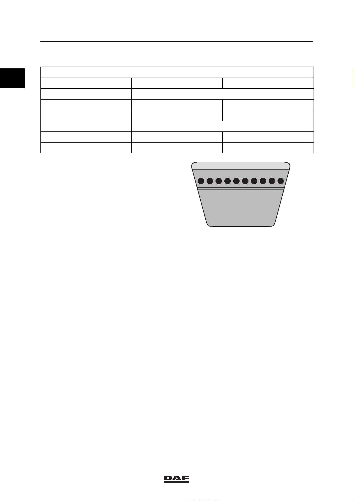
V-BELT TENSION
Belt tension, “AVX” raw-edge
Multiple-V-belt Single-V-belt
Setting tension 1200 600
Test tension ≥800 ≥400
Minimum tension 500 250
Adjusting tension 700 350
(1) Raw-edge V-belts can be recognised by the absence
of textile fabric in the rubber, with the exception of the
top of the belt edge, on the edges and the insides of
the belt (polished belt edges). Version: either toothed
or non-toothed.
(2) After fitting the new V-belt, set the pre-tension to the
“setting tension” and after a trial run check whether the
pre-tension complies with the “test tension”. If the
tension reading is lower than the “test tension”
specified in the table, set the V-belt to the minimum
“test tension”.
1
V-belts in Newtons (N)
New V-belt
Worn V-belt
2
3
(3) If the V-belt tension is lower than the “minimum
tension”, set the belt to the “adjusting tension”.
M2121
2-2
ǹ 200335

2
TECHNICAL DATA
95XF series XF engine
Cylinder liner
Height above cylinder block 0.02 - 0.10 mm
Cylinder head
Minimum height after overhaul 119.50 mm
Test pressure using air (max. pressure) 1.5 bar
Valve clearance
Valve clearance (cold/hot)
inlet 0.50 mm
exhaust 0.50 mm
Valve opening
Valve opening at 1 mm valve clearance 0.3 - 0.7 mm
Axial play
Crankshaft axial play 0.06 - 0.32 mm
Camshaft axial play 0.10 - 0.55 mm
Idler gear axial play 0.05 - 0.25 mm
Gear backlash
Idler gear - crankshaft gear 0.02 - 0.21 mm
Idler gear - fuel-pump gear 0.02 - 0.22 mm
Idler gear - camshaft gear 0.02 - 0.21 mm
Camshaft gear - compressor gear 0.02 - 0.22 mm
Fuel pump gear - steering pump gear 0.02 - 0.19 mm
Oil pump idler gear - oil pump gear 0.02 - 0.20 mm
Crankshaft gear - oil pump idler gear 0.02 - 0.20 mm
0
Number of teeth, timing gears
Crankshaft gear 35
Idler gear 54
Fuel pump gear 70
Camshaft gear 70
Air compressor gear 27
Fan drive housing gear 29
Steering pump gear 18
Lubricating oil pump idler gear 34
Fan drive
Heat gear wheel for max. 30 min. 245_C
Compression pressure
Differences in compression pressure 15%
Flywheel/starter ring gear
Axial variation, measured at a radial distance
of 210 mm
Starter ring gear warm up max. 185_C
0.10 mm
ǹ 200335
2-3

TECHNICAL DATA
2
XF engine 95XF series
2.2 TIGHTENING TORQUES
0
The tightening torques stated in this section are
different from the standard tightening torques
stated in the overview of the standard tightening
torques. The other threaded connections which
are not stated must therefore be tightened to the
tightening torque stated in the overview of
standard tightening torques.
When attachment bolts and nuts are to be
replaced, it is important that they are of exactly
the same length and property class as the ones
removed unless stated otherwise.
Starter motor
Attachment nuts 73 Nm
Alternator
Alternator bracket attachment bolts 55 Nm
Alternator attachment bolts 50 Nm
Pulley attachment nut, version 55A 70 Nm
Pulley attachment nut, version 95A 70 Nm
Air compressor
M12 attachment bolts for compressor 110 Nm
M8 attachment bolts for bracket 30 Nm
M10 attachment bolts for bracket 60 Nm
Compressor gear flange bolt 120 Nm
M14 cylinder head threaded coupling 40 Nm
M26 cylinder head threaded coupling 90 Nm
Delivery pipe reducer valve 75 Nm
Suction and pressure line unions 90 Nm
(1)
Air-conditioning compressor
M12 attachment bolts for compressor bracket 110 Nm
M10 attachment bolts for compressor 60 Nm
Exhaust manifold
Fit gasket with steel side towards manifold
Sleeved attachment bolts 65 Nm
Heat shield attachment bolts 30 Nm
(1)
(1)
2-4
ǹ 200335

2
TECHNICAL DATA
95XF series XF engine
Inlet manifold
Attachment bolts 60 Nm
Glow plug attachment nut 55 Nm
Air inlet hose clamps 12 Nm
0
Turbocharger
Heat shield attachment bolts 30 Nm
Turbine housing clamp plate attachment nut 15 Nm
Attachment nuts, exhaust manifold
flange/turbocharger
Elbow on turbocharger 40 Nm
Oil supply pipe banjo bolt 90 Nm
(1) Secure with Loctite 243
(2) Apply Copaslip to secure
60 Nm
(1)
(2)
ǹ 200335
2-5
0
TECHNICAL DATA
2
XF engine 95XF series
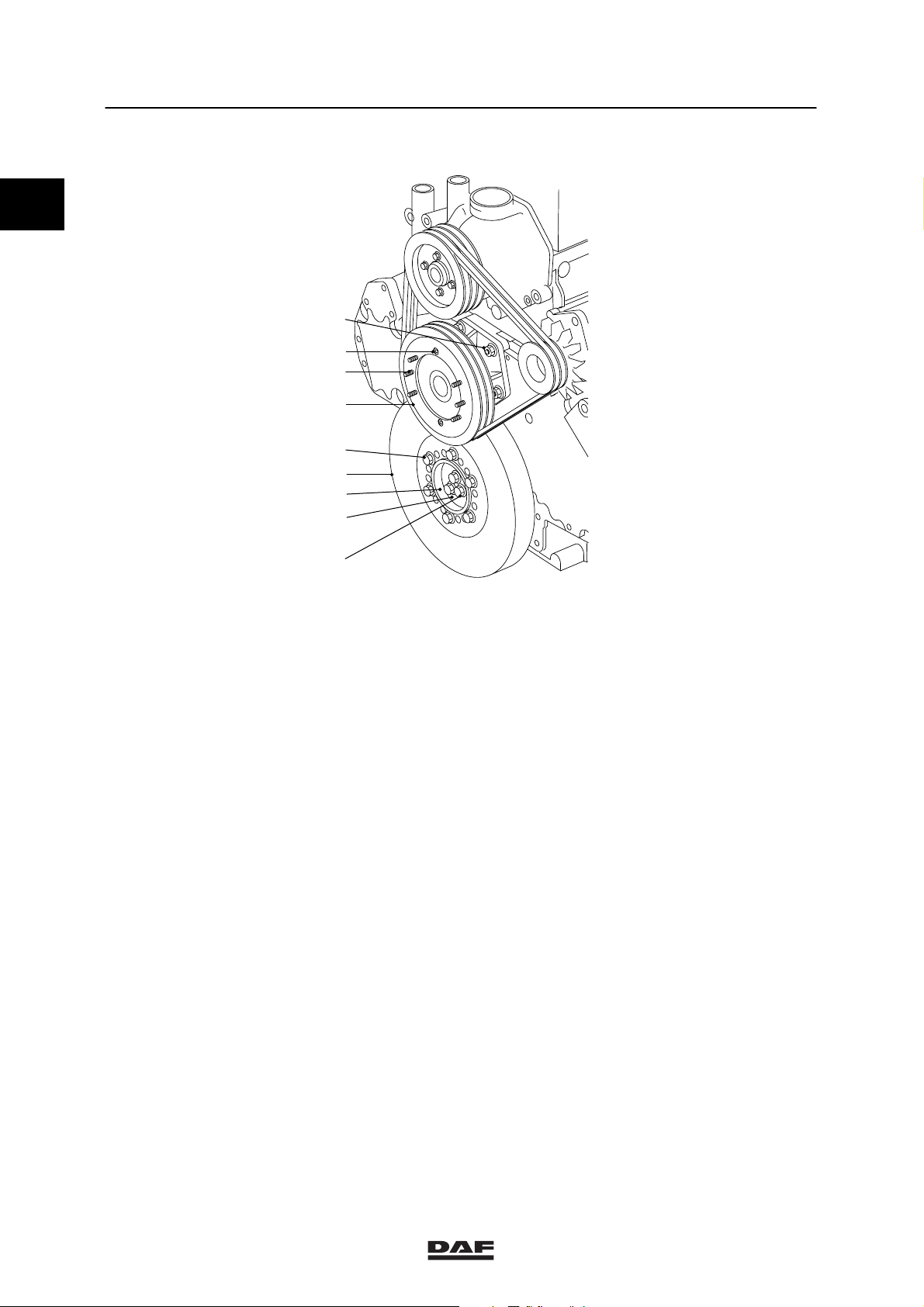
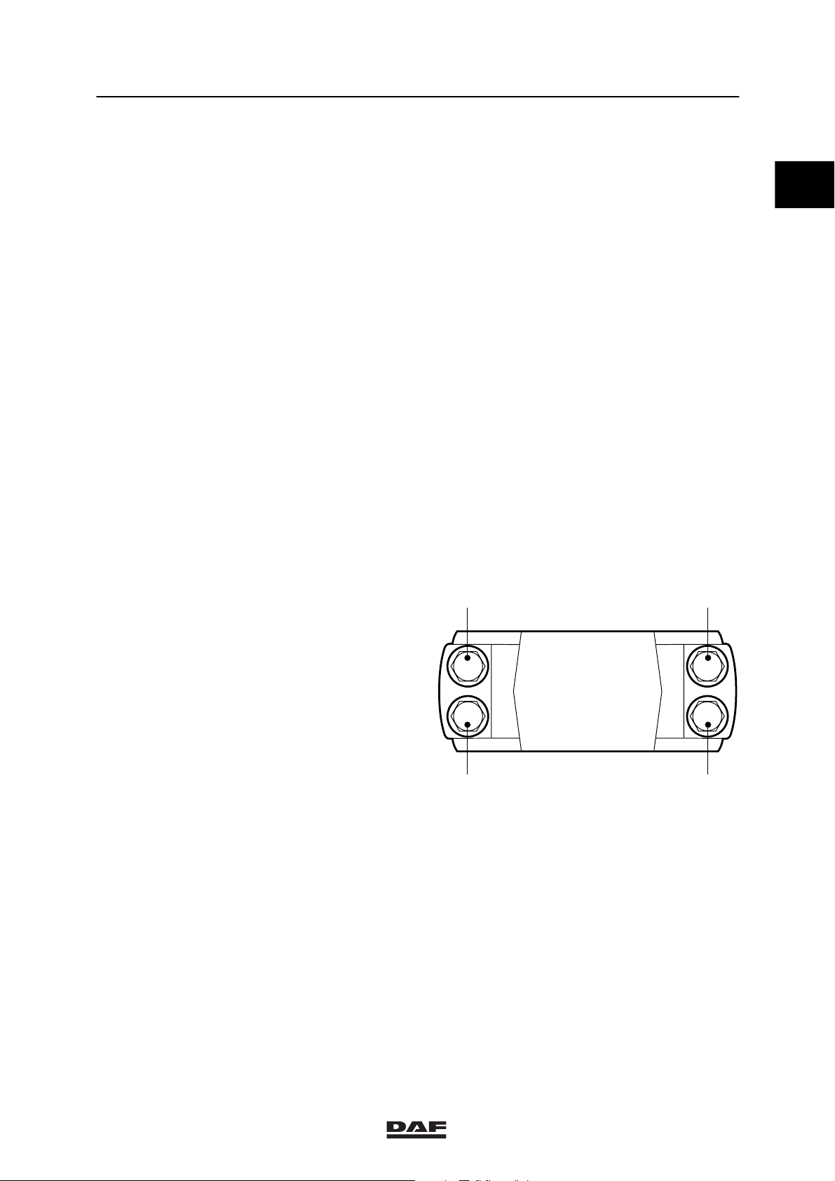
Vibration damper and fan drive
8
9
7
6
5
4
3
2
1
Vibration damper hub attachment bolts (1) in 4
phases:
st
1
phase, all attachment bolts 100 Nm
2ndphase, all attachment bolts 100 Nm
3rdphase, all attachment bolts 100 Nm
4thphase, all attachment bolts 100 Nm
Attachment bolts, vibration damper (5) 110 Nm
Attachment nuts, fan drive (8) 60 Nm
Attachment bolts, fan pulley (9) 30 Nm
Attachment nuts, fan clutch (7) 25 Nm
(1) Tighten the attachment bolts evenly
(2) Secure with Loctite 243
M200945
(1)
(1)
(1)
(1)
(2)
(2)
2-6
ǹ 200335
2
TECHNICAL DATA
95XF series XF engine
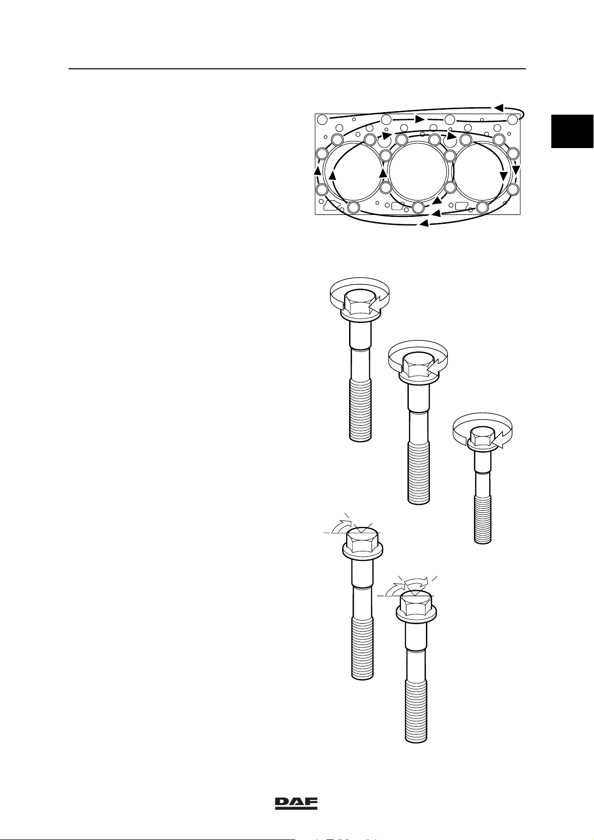
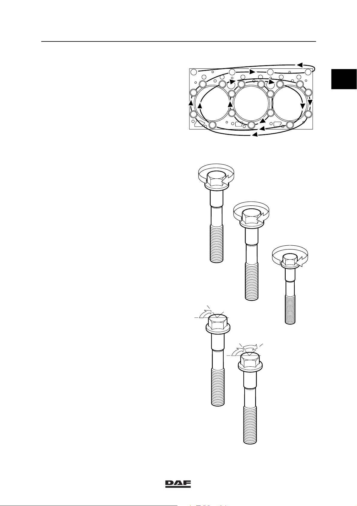
Cylinder head attachment bolts
Cylinder head bolts must only be used once .
So the cylinder head bolts should always be
replaced. The new cylinder head bolts have a
red/brown sealant on the thread.
Note:
- Because of the sealant used on the cylinder
head bolts, their untightening torque may be
very high!
- All M16 and M12 threaded holes must be
carefully cleaned with a screw tap before
the bolts are fitted.
- Once the bolts have been tightened to the
specified torque, the angular displacement
of the M16 bolts must immediately be
started.
- The sealant cannot be applied later.
Tightening cylinder head attachment bolts
16
15
21
17
11
10
50 Nm
18 19
17
6
5
4
20
8
2
3
12
13
14
9
M200562
0
Note:
Apply a drop of oil underneath the bolt heads
(on their abutting surface). Sealant also reduces
the frictional resistance, which means that no oil
must be applied to the thread.
st
phase
1
Tighten M16 in the order
indicated
2ndphase
Tighten M16 in the order
indicated
Tighten M12 in the order
indicated
3rdphase
M16 in the order
indicated
in two steps of 60_ angular
(1) Apply a drop of oil to bolts M16 and M12 on the
abutting surface of the bolt heads.
(1)
50 Nm
150 Nm
(1)
94 Nm
displacement
60
III
150 Nm
M16
I
M16
94 Nm
II
M12
II
M16
60
ǹ 200335
M16
III
M200563
2-7

TECHNICAL DATA
2
XF engine 95XF series
0
Timing gear
Camshaft locking plate attachment bolts 30 Nm
Attachment bolts, fuel pump drive shaft locking
plate
Timing case attachment bolts 30 Nm
Timing cover attachment bolts:
M10 attachment bolts 60 Nm
M8 attachment bolts 25 Nm
Timing cover protection plate attachment bolt 15 Nm
Camshaft gear attachment bolt 425 Nm
Idler gear attachment bolt 170 Nm
Attachment bolt, fuel pump gear wheel 260 Nm
Attachment bolt, silencer 30 Nm
Steering pump gear attachment nut 80 Nm
Steering pump intake pipe banjo bolt 90 Nm
Steering pump delivery pipe banjo bolt 40 Nm
Compressor gear attachment nut 120 Nm
(1) Secure with Loctite 243
30 Nm
(1)
(1)
(1)
(1)
(1)
(1)
2-8
ǹ 200335
2
TECHNICAL DATA
95XF series XF engine
Flywheel housing
Attachment bolts 110 Nm
Sealant to be used when fitting flywheel
housing
Flywheel
Attachment bolts
Without PTO 260 Nm
Without PTO spanner size 21 mm 260 Nm + 90_ angular displacement
With PTO 260 Nm + 150_ angular displacement
Engine mountings on timing gear end
Cylinder block bracket attachment bolts 92 Nm
Chassis engine bracket attachment bolts 73 Nm
Vibration damper engine bracket attachment
bolts
Engine mountings on flywheel end
Flywheel housing engine bracket attachment
bolts
Chassis engine bracket attachment bolts 73 Nm
Vibration damper engine bracket attachment
bolts
Loctite 510
225 Nm + 60_ angular displacement
260 Nm
225 Nm + 60_ angular displacement
(1)
(1)
+90_ angular displacement
0
Engine hanger brackets
Attachment bolts 110 Nm
Valve gear
Valve cover attachment bolts 25 Nm
Rocker setting bolt lock nut 40 Nm
Bridge piece setting bolt lock nut 40 Nm
Lubricating oil strip/rocker seat attachment
bolts
DEB set screw nut 25 Nm
Solenoid valve 20 Nm
Wiring harness attachment bolt 9 Nm
Valve sleeve attachment bolts 30 Nm
Tighten the valve sleeve bolts in the
sequence shown.
110 Nm
3
5
1
11
13
9157
2
6
814
41210
M200942
(1) Secure with Loctite 243
ǹ 200335
2-9

0
TECHNICAL DATA
XF engine 95XF series
2
2-10
ǹ 200335

2
TECHNICAL DATA
95XF series XF engine cooling system
3. XF ENGINE COOLING SYSTEM
3.1 GENERAL
Thermostat
Thermostat opening temperatures:
- thermostat opens at 83_C
- thermostat opened at least 12 mm at 95_C
Thermostat seat Loctite 638
Water pump
Maximum radial play 0.16 - 0.20 mm
Expansion tank pressure cap
Pressure relief valve opening pressure 0.75 bar
Underpressure valve opening pressure 0.1 bar
Pressure testing the cooling system
Test pressure 0.5 - 0.7 bar
0
ǹ 200335
3-1

TECHNICAL DATA
2
XF engine cooling system 95XF series
3.2 TIGHTENING TORQUES
0
The tightening torques stated in this section are
different from the standard tightening torques
stated in the overview of the standard tightening
torques. The other threaded connections which
are not stated must therefore be tightened to the
tightening torque stated in the overview of
standard tightening torques.
When attachment bolts and nuts are to be
replaced, it is important that they are of exactly
the same length and property class as the ones
removed unless stated otherwise.
Water pump
M8 attachment bolts 30 Nm
Threaded coupling 35 Nm
Coolant pipe
Attachment bolts 54 Nm
Coolant pipe threaded coupling 90 Nm
Coolant pipe plug 30 Nm
Thermostat housing
Attachment bolts 30 Nm
Plug 35 Nm
Radiator
Attachment nuts 70 Nm
3.3 FILLING CAPACITIES
Cooling system capacity approx. 50 litres
Cooling system capacity with ZF-intarder approx. 60 litres
3-2
ǹ 200335

2
TECHNICAL DATA
95XF series XF engine lubrication system
4. XF ENGINE LUBRICATION SYSTEM
4.1 GENERAL
Oil pressure
Oil pressure at engine idling speed 1 bar (warm engine)
Oil pressure at full-load engine speed 3,5 - 4.5 bar
Oil filter
Type disposable filter
Quantity 1
Installation in the oil circuit full flow
Opening pressure of bypass valve at a
pressure difference of
Oil cooler
Opening pressure of bypass valve at a
pressure difference of
Oil section test pressure 6 bar
2,5 0.3 bar
2 bar
0
ǹ 200335
4-1

TECHNICAL DATA
2
XF engine lubrication system 95XF series
4.2 TIGHTENING TORQUES
0
The tightening torques stated in this section are
different from the standard tightening torques
stated in the overview of the standard tightening
torques. The other threaded connections which
are not stated must therefore be tightened to the
tightening torque stated in the overview of
standard tightening torques.
When attachment bolts and nuts are to be
replaced, it is important that they are of exactly
the same length and property class as the ones
removed unless stated otherwise.
Fuel filter
Attachment bolts, fuel filter/water pipe
connection
Fuel pump filter head banjo bolt 40 Nm
Lubricating oil strip/rocker seats
Attachment bolts 110 Nm
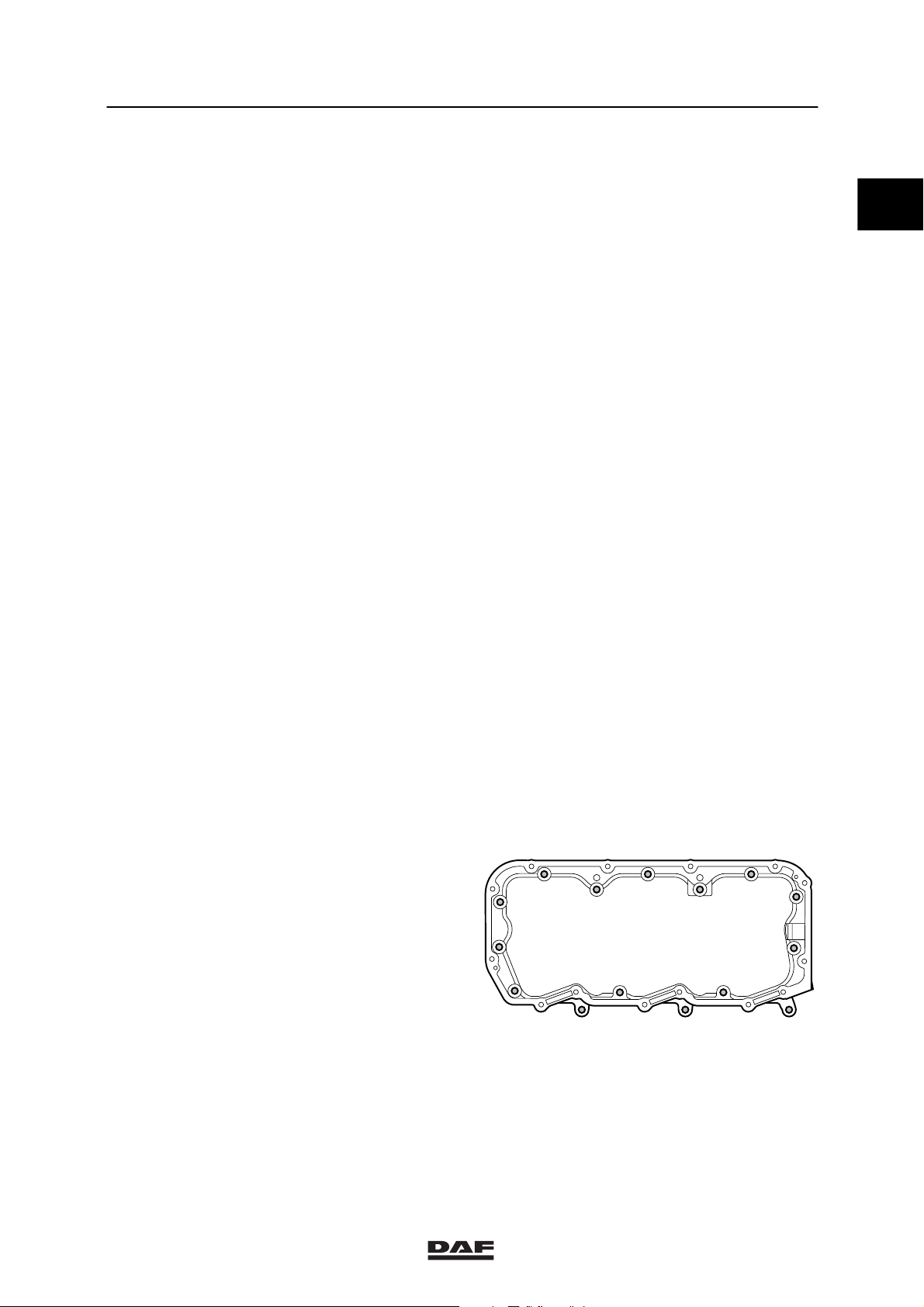
Oil sump
Clamp attachment bolts 25 Nm
Oil drain plug 60 Nm
Oil pump
Attachment bolts for oil pump housing sections 30 Nm
Attachment bolts connecting oil pump to main
bearing cap
Delivery pipe attachment bolts 30 Nm
Idler gear central bolt 60 Nm
40 Nm
60 Nm
(1)
(1)
(1)
Strainer
Bracket attachment bolts 30 Nm
Lubricating oil filter
Lubricating oil filter housing attachment bolts 50 Nm
Oil filter 45 Nm
Coupling in lubricating oil filter head 60 Nm
Bypass pressure regulator
Plug 80 Nm
(1)
(2)
(3)
4-2
ǹ 200335
2
TECHNICAL DATA
95XF series XF engine lubrication system
Oil cooler
Attachment bolts connecting oil cooler to
cylinder block
Coolant supply pipe union 90 Nm
Plug, adjustable banjo connection 90 Nm
Banjo bolt, adjustable banjo connection 90 Nm
Centrifugal oil filter
Central bolt 20 Nm
Oil discharge pipe union 50 Nm
Dip stick
Threaded coupling 60 Nm
(1) Secure with Loctite 243
(2) Secure with Loctite 572
(3) Secure with Loctite 2701
Oil sprayer
Banjo bolt M14 for oil sprayer with locking
plate
M10 banjo bolt for oil sprayer 30 Nm
50 Nm
30 Nm
0
Main bearing caps
Main bearing cap attachment bolts 150 Nm + 120_ angular displacement
Big-end bearing caps
Attachment bolts, big-end bearing caps
st
1
phase,
sequence 1-2-3-4
nd
phase,
2
sequence 4-3-2-1
rd
phase,
3
sequence 1-2-3-4
35 Nm
45 Nm
60_ angular
displacement
(2)
1 4
32
(1) Apply a drop of oil to thread and contact surface.
(2) Connecting rod bolts are to be used once and
tightened as instructed.
When fitting the connecting rod in the engine, apply a
drop of oil to the threads and contact surfaces of the
connecting rod bolts.
(1)
M200661
ǹ 200335
4-3

TECHNICAL DATA
XF engine lubrication system 95XF series
4.3 FILLING CAPACITIES
2
0
Lubrication system
Total capacity, including oil cooler and oil filter approx. 32 litres
Oil sump capacity, maximum level approx. 25 litres
Oil sump capacity, minimum level approx. 17 litres
4-4
ǹ 200335

2
TECHNICAL DATA
95XF series XE engine
5. XE ENGINE
5.1 GENERAL
Types XE 280 C
XE 315 C/C2
XE 355 C
XE 390 C
Version Euro 3 (C), (C2 = 4 öko), water-cooled,
four-stroke diesel engine with direct fuel
injection, 4-valves per cylinder and
turbo-intercooling.
Number of cylinders 6
Bore x stroke 130 x 158 mm
Swept volume 12.58 l
Compression ratio 16.0 : 1
Firing order 1-5-3-6-2-4
Weight approx. 1,080 kg
ENGINE TYPE
XE 280 C 280 at 2000 1750 at 1000 - 1500
XE 315 C/C2 315 at 2000 1900 at 1100 - 1500
P(kW)atrpm M(Nm)atrpm
0
XE 355 C 355 at 2000 2100 at 1100 - 1500
XE 390 C 390 at 1900 2350 at 1100 - 1500
ENGINE TYPE IDLING SPEED MAX. NO LOAD SPEED
XE 280 C 525 - 575 approx. 2300
XE 315 C/C2 525 - 575 approx. 2300
XE 355 C 525 - 575 approx. 2300
XE 390 C 525 - 575 approx. 2300
ǹ 200335
5-1

0
TECHNICAL DATA
2
XE engine 95XF series
V-BELT TENSION
Belt tension, “AVX” raw-edge
Multiple-V-belt Single-V-belt
Setting tension 1200 600
Test tension ≥800 ≥400
Minimum tension 500 250
Adjusting tension 700 350
(1) Raw-edge V-belts can be recognised by the absence
of textile fabric in the rubber, with the exception of the
top of the belt edge, on the edges and the insides of
the belt (polished belt edges). Version: either toothed
or non-toothed.
(2) After fitting the new V-belt, set the pre-tension to the
“setting tension” and after a trial run check whether the
pre-tension complies with the “test tension”. If the
tension reading is lower than the “test tension”
specified in the table, set the V-belt to the minimum
test tension.
1
V-belts in Newtons (N)
New V-belt
Worn V-belt
2
3
(3) If the V-belt tension is lower than the “minimum
tension”, set the belt to the “adjusting tension”.
Cylinder liner
Height above cylinder block 0.02 - 0.10 mm
Cylinder head
Minimum height after overhaul 119.50 mm
Test pressure using air (hot) 1.5 bar
Valve clearance
Valve clearance (cold/hot)
inlet 0.50 mm
exhaust 0.50 mm
Valve opening
Valve opening at 1 mm valve clearance 0.3 - 0.7 mm
M2121
5-2
ǹ 200335

2
TECHNICAL DATA
95XF series XE engine
Axial play
Crankshaft axial play 0.06 - 0.32 mm
Camshaft axial play 0.10 - 0.55 mm
Idler gear axial play 0.05 - 0.25 mm
Gear backlash
Idler gear - crankshaft gear 0.02 - 0.21 mm
Idler gear pump housing camshaft gear 0.02 - 0.22 mm
Idler gear - camshaft gear 0.02 - 0.21 mm
Camshaft gear - compressor gear 0.02 - 0.22 mm
Pump housing camshaft gear - steering pump
gear
Oil pump idler gear - oil pump gear 0.02 - 0.20 mm
Crankshaft gear - oil pump idler gear 0.02 - 0.20 mm
Number of teeth, timing gears
Crankshaft gear 35
Idler gear 54
Pump housing camshaft gear 70
Camshaft gear 70
Air compressor gear 27
Fan drive housing gear 29
Steering pump gear 18
Lubricating oil pump idler gear 34
0.02-0.19mm
0
Fan drive
Heat gear wheel for max. 30 min. 245_C
Compression pressure
Differences in compression pressure max. 15%
Flywheel/starter ring gear
Axial variation, measured at a radial distance
of 210 mm
Starter ring gear warm up max. 185_C
0.10 mm
ǹ 200335
5-3

TECHNICAL DATA
2
XE engine 95XF series
5.2 TIGHTENING TORQUES
0
The tightening torques stated in this section are
different from the standard tightening torques
stated in the overview of the standard tightening
torques. The other threaded connections which
are not stated must therefore be tightened to the
tightening torque stated in the overview of
standard tightening torques.
When attachment bolts and nuts are to be
replaced, it is important that they are of exactly
the same length and property class as the ones
removed unless stated otherwise.
Starter motor
Attachment nuts 73 Nm
Alternator
Alternator bracket attachment bolts 55 Nm
Alternator attachment bolts 50 Nm
Pulley attachment nut, version 55A 70 Nm
Pulley attachment nut, version 95A 70 Nm
Air compressor
M12 attachment bolts 110 Nm
M8 attachment bolts for bracket 30 Nm
M10 attachment bolts for bracket 60 Nm
Compressor gear flanged nut 120 Nm
M14 cylinder head threaded coupling 40 Nm
M26 cylinder head threaded coupling 90 Nm
Delivery pipe reducer valve 75 Nm
Suction and pressure line unions 90 Nm
(1)
Air-conditioning compressor
M12 attachment bolts for compressor bracket 110 Nm
M10 attachment bolts for compressor 60 Nm
Exhaust manifold
Fit gasket with steel side towards manifold
Sleeved attachment bolts 65 Nm
Heat shield attachment bolts 30 Nm
(1)
(1)
5-4
ǹ 200335

2
TECHNICAL DATA
95XF series XE engine
Inlet manifold
Attachment bolts 60 Nm
Glow plug attachment nut 55 Nm
Air inlet hose clamps 12 Nm
0
Turbocharger
Heat shield attachment bolts 30 Nm
Turbine housing clamp plate attachment nut 15 Nm
Attachment nuts
Exhaust manifold flange/turbocharger 60 Nm
Elbow on turbocharger 40 Nm
Oil supply pipe banjo bolt 90 Nm
(1) Apply Loctite 243 to secure
(2) Apply Copaslip to secure
(1)
(2)
ǹ 200335
5-5

0
TECHNICAL DATA
2
XE engine 95XF series
Vibration damper and fan drive
8
9
7
6
5
4
3
2
1
Vibration damper hub attachment bolts (1) in 4
phases:
st
1
phase, all attachment bolts 100 Nm
2ndphase, all attachment bolts 100 Nm
3rdphase, all attachment bolts 100 Nm
4thphase, all attachment bolts 100 Nm
Attachment bolts, vibration damper (5) 110 Nm
Attachment nuts, fan drive (8) 60 Nm
Attachment bolts, fan pulley (9) 30 Nm
Attachment nuts, fan clutch (7) 25 Nm
(1) Tighten the attachment bolts evenly
(2) Secure with Loctite 243
M200945
(1)
(1)
(1)
(1)
(2)
(2)
5-6
ǹ 200335
2
TECHNICAL DATA
95XF series XE engine
Cylinder head attachment bolts
Cylinder head bolts must only be used once.So
the cylinder head bolts should always be
replaced. The new cylinder head bolts have a
red/brown sealant on the thread.
Note:
- Because of the sealant used on the cylinder
head bolts, their untightening torque may be
very high!
- All M16 and M12 threaded holes must be
carefully cleaned with a screw tap before
the bolts are fitted.
- Once the bolts have been tightened to the
specified torque, the angular displacement
of the M16 bolts must immediately be
started.
- The sealant cannot be applied later.
Tightening cylinder head attachment bolts
16
15
21
17
11
10
50 Nm
18 19
17
6
5
4
20
8
2
3
12
13
14
9
M200562
0
Note:
Apply a drop of oil underneath the bolt heads
(on their abutting surface). Sealant also reduces
the frictional resistance, which means that no oil
must be applied to the thread.
st
phase
1
Tighten M16 in the
order indicated
2ndphase
Tighten M16 in the
order indicated
Tighten M12 in the
order indicated
3rdphase
M16 in the order
indicated in two stages of 60_ angular
(1) Apply a drop of oil to bolts M16 and M12 on the
abutting surface of the bolt heads.
(1)
50 Nm
150 Nm
(1)
94 Nm
displacement
60
III
150 Nm
M16
I
M16
94 Nm
II
M12
II
M16
60
ǹ 200335
M16
III
M200563
5-7

TECHNICAL DATA
2
XE engine 95XF series
0
Timing gear
Camshaft locking plate attachment bolts 30 Nm
Pump housing camshaft locking plate
attachment bolts
Timing case attachment bolts 25 Nm
Timing cover attachment bolts:
M10 attachment bolts 60 Nm
M8 attachment bolts 25 Nm
Timing cover protection plate attachment bolt 15 Nm
Camshaft gear attachment bolt 425 Nm
Idler gear attachment bolt 170 Nm
Pump housing camshaft gear attachment bolt 260 Nm
Compressor gear attachment nut 120 Nm
Steering pump gear attachment nut 80 Nm
Suction pipe banjo bolt 90 Nm
Delivery pipe banjo bolt 40 Nm
(1) Apply Loctite 243 to secure
30 Nm
(1)
(1)
(1)
(1)
(1)
5-8
ǹ 200335

2
TECHNICAL DATA
95XF series XE engine
Flywheel housing
Attachment bolts 110 Nm
Sealant to be used when fitting flywheel
housing
Flywheel
Attachment bolts
Without PTO 260 Nm + 90_ angular displacement
With PTO 260 Nm + 150_ angular displacement
Engine mountings on timing gear end
Cylinder block bracket attachment bolts 92 Nm
Chassis engine bracket attachment bolts 73 Nm
Vibration damper engine bracket attachment
bolts
Engine mountings on flywheel end
Flywheel housing engine bracket attachment
bolts
Chassis engine bracket attachment bolts 73 Nm
Vibration damper engine bracket attachment
bolts
Engine hanger brackets
Attachment bolts 110 Nm
Loctite 510
225 Nm + 60_ angular displacement
260 Nm
225 Nm + 60_ angular displacement
(1)
0
Valve gear
Valve cover attachment bolts 25 Nm
Rocker setting bolt lock nut 40 Nm
Bridge piece setting bolt lock nut 40 Nm
Lubricating oil strip/rocker seat attachment
bolts
DEB set screw nut 25 Nm
Solenoid valve 20 Nm
Wiring harness attachment bolt 9 Nm
Valve sleeve attachment bolts 30 Nm
Tighten the valve sleeve bolts in the sequence
shown.
(1) Apply Loctite 243 to secure
110 Nm
3
5
1
11
13
9157
2
6
814
41210
M200942
ǹ 200335
5-9

0
TECHNICAL DATA
XE engine 95XF series
2
5-10
ǹ 200335

2
TECHNICAL DATA
95XF series XE engine cooling system
6. XE ENGINE COOLING SYSTEM
6.1 GENERAL
Thermostat
Thermostat opening temperatures:
- thermostat opens at 83_C
- thermostat opened at least 12 mm at 95_C
Thermostat seat Loctite 638
Water pump
Maximum radial play 0.16 - 0.20 mm
Expansion tank pressure cap
Pressure relief valve opening pressure 0.75 - 0.9 bar
Underpressure valve opening pressure 0.1 bar
Pressure testing the cooling system
Test pressure 0.5 - 0.7 bar
0
ǹ 200335
6-1

TECHNICAL DATA
2
XE engine cooling system 95XF series
6.2 TIGHTENING TORQUES
0
The tightening torques stated in this section are
different from the standard tightening torques
stated in the overview of the standard tightening
torques. The other threaded connections which
are not stated must therefore be tightened to the
tightening torque stated in the overview of
standard tightening torques.
When attachment bolts and nuts are to be
replaced, it is important that they are of exactly
the same length and property class as the ones
removed unless stated otherwise.
Water pump
M8 attachment bolts 30 Nm
Threaded coupling 35 Nm
Coolant pipe
Attachment bolts 54 Nm
Coolant pipe threaded coupling 90 Nm
Plug 35 Nm
Thermostat housing
Attachment bolts 30 Nm
Plug 35 Nm
Radiator
Attachment nuts 70 Nm
6.3 FILLING CAPACITIES
Cooling system capacity approx. 50 litres
Cooling system capacity with ZF-intarder approx. 60 litres
6-2
ǹ 200335

2
TECHNICAL DATA
95XF series XE engine lubrication system
7. XE ENGINE LUBRICATION SYSTEM
7.1 GENERAL
Oil pressure
Oil pressure at engine idling speed 1 bar (warm engine)
Oil pressure at full-load engine speed 3.5 - 4.5 bar
Oil filter
Type disposable filter
Quantity 1
Installation in the oil circuit full flow
Opening pressure of bypass valve at a
pressure difference of
Oil cooler
Opening pressure of bypass valve at a
pressure difference of
Oil section test pressure 6 bar
2.5 0.3 bar
2 bar
0
ǹ 200335
7-1

TECHNICAL DATA
2
XE engine lubrication system 95XF series
7.2 TIGHTENING TORQUES
0
The tightening torques stated in this section are
different from the standard tightening torques
stated in the overview of the standard tightening
torques. The other threaded connections which
are not stated must therefore be tightened to the
tightening torque stated in the overview of
standard tightening torques.
When attachment bolts and nuts are to be
replaced, it is important that they are of exactly
the same length and property class as the ones
removed unless stated otherwise.
Fuel filter
Attachment bolts, fuel filter/water pipe
connection
Lubricating oil strip/rocker seats
Attachment bolts 110 Nm
Oil sump
Clamp attachment bolts 25 Nm
Oil drain plug 60 Nm
Oil pump
Attachment bolts for oil pump housing sections 30 Nm
Attachment bolts connecting oil pump to main
bearing cap
Oil delivery pipe attachment bolts 30 Nm
Idler gear central bolt 60 Nm
40 Nm
60 Nm
(1)
(1)
(1)
Strainer
Bracket attachment bolts 30 Nm
Lubricating oil filter
Lubricating oil filter housing attachment bolts 50 Nm
Oil filter 45 Nm
Coupling in lubricating oil filter head 60 Nm
Bypass pressure regulator
Plug 80 Nm
(1)
(2)
(3)
7-2
ǹ 200335

2
TECHNICAL DATA
95XF series XE engine lubrication system
Oil cooler
Attachment bolts connecting oil cooler to
cylinder block
Coolant supply pipe union 90 Nm
Plug, adjustable banjo connection 90 Nm
Banjo bolt, adjustable banjo connection 90 Nm
Centrifugal oil filter
Central bolt 20 Nm
Oil discharge pipe union 50 Nm
Dip stick
Threaded coupling 60 Nm
(1) Apply Loctite 243 to secure
(2) Apply Loctite 572 to secure
(3) Apply Loctite 2701 to secure
50 Nm
0
ǹ 200335
7-3

TECHNICAL DATA
2
XE engine lubrication system 95XF series
Oil sprayer
Oil sprayer banjo bolt 30 Nm
0
Main bearing caps
Main bearing cap attachment bolts 150 Nm + 120_ angular displacement
Big-end bearing caps
Attachment bolts (1) for cracked big-end
bearing caps
st
1
phase, order 100 Nm
nd
2
phase, order 175 15 Nm
rd
3
phase, order 60_ angular
displacement
(2)
1
2
1
Attachment bolts, big-end bearing caps
st
1
phase,
sequence 1-2-3-4
nd
phase,
2
sequence 4-3-2-1
rd
phase,
3
sequence 1-2-3-4
35 Nm
45 Nm
60_ angular
displacement
(2)
1 4
(1)
5
4
3
M2 01 285
Attachment bolts, big-end bearing caps
XE390C
st
1
phase,
sequence 1-2-3-4
nd
phase,
2
sequence 4-3-2-1
rd
phase,
3
sequence 1-2-3-4 60_ angular
(1) Apply a drop of oil to thread and contact surface.
(2) Connecting rod bolts are to be used once and
tightened as instructed. When fitting the connecting
rod in the engine, apply a drop of oil to the threads
and contact surfaces of the connecting rod bolts.
50 Nm
80 Nm
displacement
(2)
32
M200661
7-4
ǹ 200335

2
95XF series XE engine lubrication system
7.3 FILLING CAPACITIES
TECHNICAL DATA
Lubrication system
Total capacity, including oil cooler and oil filter approx. 32 litres
Oil sump capacity, maximum level approx. 25 litres
Oil sump capacity, minimum level approx. 17 litres
0
ǹ 200335
7-5

0
TECHNICAL DATA
XE engine lubrication system 95XF series
2
7-6
ǹ 200335

2
DIAGNOSIS
95XF series Contents
CONTENTS
Page Date
1. TRACTIVE PROBLEMS 1-1 0008................................................ ......
1.1 Introduction 1-1 0008...................................................... ......
1.2 Acceleration test (engine model with conventional fuel system) 1-3 0008.......... ......
1.3 Acceleration test (engine model with UPEC fuel system) 1-7 0008................ ......
1.4 Acceleration test form 1-11 0008............................................. .....
1.5 Acceleration test using DAVIE 1-12 0008...................................... .....
2. XF ENGINE 2-1 0008........................................................... ......
2.1 Fault-finding table 2-1 0008................................................. ......
3. COOLING SYSTEM XF ENGINE 3-1 0008......................................... ......
3.1 Fault-finding table 3-1 0008................................................. ......
4. LUBRICATING OIL SYSTEM XF ENGINE 4-1 0008................................. ......
4.1 Fault-finding table 4-1 0008................................................. ......
5. XE ENGINE 5-1 0008........................................................... ......
5.1 Fault-finding table for engine functions 5-1 0008............................... ......
5.2 Fault-finding table for vehicle functions 5-9 0008............................... ......
1
6. COOLING SYSTEM XE ENGINE 6-1 0008......................................... ......
6.1 Fault-finding table 6-1 0008................................................. ......
7. LUBRICATING OIL SYSTEM XE ENGINE 7-1 0008................................. ......
7.1 Fault-finding table 7-1 0008................................................. ......
ǹ 0008
1

1
DIAGNOSIS
Contents 95XF series
2
2
ǹ 0008

2
DIAGNOSIS
95XF series Tractive problems
1. TRACTIVE PROBLEMS
1.1 INTRODUCTION
There may be several reasons for improper
vehicle performance.
Some of these may be mechanical, others are
particularly also of a psychological nature.
It is therefore important to properly identify the
problem.
Try to get as much information as possible from
the customer or driver.
- When does the vehicle not perform
properly?
- In what road or weather conditions?
- How is the vehicle loaded?
- Is the vehicle not being compared with a
vehicle with completely different
specifications, for instance engine power?
1
- Is the vehicle being driven in the correct
engine speed range?
If the answers are unsatisfactory, ask the
customer or driver for facts.
- Tachograph cards of trips
- Reliable consumption figures of trips
ǹ 0008
1-1

1
DIAGNOSIS
2
Tractive problems 95XF series
Following proper identification of the complaint,
vehicle performance can be tested by an
acceleration test.
If the vehicle fails to pass the acceleration test, a
boost pressure curve may be plotted as an aid
to identify the cause.
Note:
Checking the boost pressure will in general only
make sense after the vehicle has covered at
least 20,000 km.
The test sheets are available through the DAF
organisation.
For plotting a boost pressure curve, see Group 4
of the workshop manual.
1-2
ǹ 0008

2
DIAGNOSIS
95XF series Tractive problems
1.2 ACCELERATION TEST
(engine model with conventional fuel system)
The acceleration test is required to acquire an
effective understanding of the fuel consumption
and tractive force of a vehicle. When carrying
out the test the legal regulations should be
observed and maximum security be ensured.
Compared with other diagnostic tools, this test is
a fast and cheap way of checking whether the
vehicle meets DAF’s requirements and,
therefore, whether or not the complaint is
justified.
During the acceleration test the time required to
accelerate the loaded vehicle from starting
speed to final speed is measured. (Weight of
entire combination at least 75% of the train
weight, GCW).
To eliminate weather influences and road
conditions, this test must be done in both driving
directions. The average acceleration time is
obtained by averaging both measured times.
1
The maximum acceleration time, the speeds
between which the time is to be measured and
the gear to be engaged for the various vehicle
configurations is calculated using the DAF
“Topec” route simulation computer program.
For this purpose, “Topec” needs the following
and other vehicle data:
- vehicle type
- height of the entire vehicle combination
- weight of entire vehicle combination (at
least 75% of the train weight)
- aerodynamic influences, e.g. roof spoilers,
fenders, etc.
- engine type
- gearbox type and reduction
- rear axle type and axle reduction
-tyresize
- cab type.
ǹ 0008
1-3

1
DIAGNOSIS
2
Tractive problems 95XF series
Before starting the acceleration test
- Check the tyre pressure of the entire vehicle
combination. Also check the tyres for a
deviating wear pattern.
- Examine the complete condition of the
trailer or semi-trailer.
- Check the entire vehicle combination for
adverse aerodynamic influences, for
instance loose tarpaulins, wrongly adjusted
spoilers and fenders.
- Check the vehicle and trailer or semi-trailer
for excessive road drag. Be aware of
dragging brakes.
- Check the tachograph. The speed signal
should be present.
- Check that the correct k-factor is set on the
tachograph.
- Check that the fuel pump of the engine has
been provided with the original seal.
- Check that the throttle control is able to
reach the maximum stop of the fuel pump.
Acceleration test
1. Use the “Acceleration test form” in the
workshop manual.
2. Check the activities as set out under
“Before starting the acceleration test”.
3. Choose a test route where the difference
between the measured times in both
directions does not exceed 15%. If the
difference in time exceeds 15%, find
another test route.
4. Establish the starting and end points on the
selected test route, to ensure that exactly
the same route can be taken in both
directions. Do the entire test at least twice
and take the average time.
1-4
ǹ 0008

2
DIAGNOSIS
95XF series Tractive problems
5. Run the drive train at operating temperature
(drive for at least 15 minutes with a loaded
vehicle).
Note:
When switched on, the air compressor and fan
consume 10 to 15 kW engine power on average.
During the test try to avoid that both consumers
are or have been switched on.
6. Before the starting point on the test route,
engage the gear specified by Topec and
make sure the vehicle speed is at least
3 km/h below the starting speed.
7. Fully depress the accelerator pedal and
(using a stopwatch) measure the time
needed to accelerate the vehicle from
starting speed to end speed.
Result of first acceleration test
If the acceleration time is not achieved, first
carry out the following work.
1
- Check the injection timing. Adjust or
optimise, if necessary.
- Check the fuel system for the presence of
air.
- Replace/clean the air filter element.
- Check the setting of the wastegate on the
turbocharger (if present).
- Check the engine brake butterfly valve for
smooth operation.
- Check the inlet air cooler exterior for dirt
deposits.
- Clean the water separator (if fitted).
- Replace the fuel filter.
- Replace/clean the fuel prefilter (if present).
ǹ 0008
1-5

DIAGNOSIS
2
Tractive problems 95XF series
- Check the suction pipe of the tank for
clogging by large pieces of foreign matter.
- Check the fuel tank for contamination.
Clean the tank with a steam cleaner, if
necessary.
1
- Check the air inlet system for any leaks.
- Check the exhaust system for any leaks.
- Check the exhaust system for blockages by
measuring the exhaust back pressure.
- Check the turbocharger wheels on the
compressor and turbine side for damage
and for deposits of salt or any other
contaminants.
- Check the banjo bolt strainer in the fuel lift
pump for dirt (if fitted).
- Check the valve and DEB play.
- Check the injection lines for damage.
- Check the fuel pump gallery pressure.
- Check the discharge pump pressure.
- Check whether the right type of components
have been fitted. Fuel pump, turbocharger,
injectors, etc.
- Check the opening pressure of the injectors.
- Clean the nozzle openings using calibrated
injector needles (DAF no. 1329371).
Repeat the acceleration test. If necessary, plot a
boost pressure curve.
Result of second acceleration test
If the specified acceleration time is not achieved,
carry out the following work.
- Remove the fuel pump from the engine.
- Check the fuel pump setting on a fuel pump
test bench.
- Repeat the acceleration test.
1-6
ǹ 0008

2
DIAGNOSIS
95XF series Tractive problems
1.3 ACCELERATION TEST
(engine model with UPEC fuel system)
The acceleration test is required to acquire an
effective understanding of the fuel consumption
and tractive force of a vehicle. When carrying
out the test the legal regulations should be
observed and maximum security be ensured.
Compared with other diagnostic tools, this test is
a fast and cheap way of checking whether the
vehicle meets DAF’s requirements and,
therefore, whether or not the complaint is
justified.
During the acceleration test the time required to
accelerate the loaded vehicle from starting
speed to final speed is measured. (Weight of
entire combination at least 75% of the train
weight, GCW).
To eliminate weather influences and road
conditions, this test must be done in both driving
directions. The average acceleration time is
obtained by averaging both measured times.
1
The maximum acceleration time, the speeds
between which the time is to be measured and
the gear to be engaged for the various vehicle
configurations is calculated using the DAF
“Topec” route simulation computer program.
For this purpose, “Topec” needs the following
and other vehicle data:
- vehicle type
- height of the entire vehicle combination
- weight of entire vehicle combination (at
least 75% of the train weight)
- aerodynamic influences, e.g. roof spoilers,
fenders, etc.
- engine type
- gearbox type and reduction
- rear axle type and axle reduction
-tyresize
- cab type.
ǹ 0008
1-7

1
DIAGNOSIS
2
Tractive problems 95XF series
Before starting the acceleration test
- Check the tyre pressure of the entire vehicle
combination. Also check the tyres for a
deviating wear pattern.
- Examine the complete condition of the
trailer or semi-trailer.
- Check the entire vehicle combination for
adverse aerodynamic influences, for
instance loose tarpaulins, wrongly adjusted
spoilers and fenders.
- Check the vehicle and trailer or semi-trailer
for excessive road drag. Be aware of
dragging brakes.
- Check the tachograph. The speed signal
should be present.
- Check that the correct k-factor is set on the
tachograph.
- Using DAVIE, check whether the pedal can
be depressed 100% with the gas pedal
position sensor.
Acceleration test
1. Use the “Acceleration test form” in the
workshop manual.
2. Check the activities as set out under
“Before starting the acceleration test”.
3. Choose a test route where the difference
between the measured times in both
directions does not exceed 15%. If the
difference in time exceeds 15%, find
another test route.
4. Establish the starting and end points on the
selected test route, to ensure that exactly
the same route can be taken in both
directions. Do the entire test at least twice
and take the average time.
1-8
ǹ 0008

2
DIAGNOSIS
95XF series Tractive problems
5. Run the drive train at operating temperature
(drive for at least 15 minutes with a loaded
vehicle).
Note:
When switched on, the air compressor and fan
consume 10 to 15 kW engine power on average.
During the test try to avoid that both consumers
are or have been switched on.
6. Connect DAVIE and follow the instructions
in DAVIE.
7. Fully depress the brake pedal during the
acceleration test.
Result of first acceleration test
If the acceleration time is not achieved, first
carry out the following work.
- Check the fuel system for the presence of
air.
- Replace/clean the air filter element.
1
- Check the setting of the wastegate on the
turbocharger (if present).
- Check the engine brake butterfly valve for
smooth operation.
- Check the inlet air cooler exterior for dirt
deposits.
- Clean the water separator (if fitted).
- Clean the fuel coarse filter.
- Check whether the hand pump on the fuel
coarse filter is tightened.
- Replace the fuel fine filter.
- Check the suction pipe of the tank for
clogging by large pieces of foreign matter.
ǹ 0008
1-9

1
DIAGNOSIS
2
Tractive problems 95XF series
- Check the fuel tank for contamination.
Clean the tank with a steam cleaner, if
necessary.
- Check the air inlet system for any leaks.
- Check the exhaust system for any leaks.
- Check the exhaust system for blockages by
measuring the exhaust back pressure.
- Check the turbocharger wheels on the
compressor and turbine side for damage
and for deposits of salt or any other
contaminants.
- Check the valve and DEB play.
- Check the injection lines for damage.
- Check the gallery pressure.
- Check the fuel lift pump output.
- Check the reducing valve.
- Check whether the right type of components
has been fitted. Turbocharger, injectors etc.
- Check the opening pressure of the injectors.
- Clean the nozzle openings using calibrated
injector needles (DAF no. 1329371).
Repeat the acceleration test. If necessary, plot a
boost pressure curve.
1-10
ǹ 0008

2
DIAGNOSIS
95XF series Tractive problems
1.4 ACCELERATION TEST FORM
General data:
Client’sname : ..........................................
Type/vehiclenumberplate : ..........................................
Typeoftrailer/semi-trailer : ..........................................
Owneroftrailer/semi-trailer : Client/Dealer/Thirdparties ...................
Date : ..........................................
Weather conditions : ..........................................
Route : ..........................................
Vehicle data:
Enginetype : ..........................................
Gearboxtype : ..........................................
Rearaxletype : ..........................................
1
Vehiclecombinationheight : ..........................................
Totalweightofvehiclecombination : ..........................................
Aerodynamic influences : ..........................................
TOPEC data:
Geartobeselected : ..........................................
Maximum acceleration time : seconds..................................
Starting speed : km/hour..................................
End speed : km/hour..................................
Acceleration test result:
Measured acceleration time : seconds..................................
Endresultofaccelerationtest : ..........................................
ǹ 0008
1-11

1
DIAGNOSIS
2
Tractive problems 95XF series
1.5 ACCELERATION TEST USING DAVIE
The acceleration test can also be carried out
using DAVIE. Collect all the required information
and, having started DAVIE, access the engine
management system installed on the vehicle
(E-gas, ASL-G or UPEC) and carefully follow the
instructions in DAVIE in order to carry out the
test correctly.
Following each test, the test results should
always be stored on a disk.
The acceleration test in DAVIE
should only be started when the
vehicle is at a complete standstill.
Because the communication
between the accelerator pedal
sensor and the unit is interrupted
briefly during starting of DAVIE, this
could lead to very dangerous
situations in a vehicle which is not
at a complete standstill.
Never switch to the direct test or
fault-finding test when driving the
vehicle.
1-12
ǹ 0008

2
DIAGNOSIS
95XF series XF engine
2. XF ENGINE
2.1 FAULT-FINDING TABLE
FAULT: ENGINE CAN BE STARTED, BUT DOES NOT RUN
Possible cause Remedy
Air in the fuel system. Bleed the fuel system.
Insufficient discharge pressure of the discharge
pump.
Contaminated banjo bolt strainer in the
discharge pump.
Water in the fuel system. Check the water separator.
Fuel filter silted up. Replace the fuel filter.
Incorrect or contaminated injectors installed. Check whether the correct injectors have been
Incorrect injection timing or incorrect fuel pump
setting.
Compression pressure too low. Check the compression pressure.
FAULT: ENGINE STARTS AND STOPS
Possible cause Remedy
Air in the fuel system. Bleed the fuel system.
Insufficient discharge pressure of the discharge
pump.
Check the discharge pump pressure.
Check the strainer for contamination.
installed. Clean contaminated injectors and set
them.
Check the injection timing and/or fuel pump
setting.
Check the discharge pump pressure.
1
Fuel filter silted up. Replace the fuel filter.
Incorrect injection timing or incorrect fuel pump
setting.
FAULT: ENGINE WILL NOT RUN IDLE
Possible cause Remedy
Air in the fuel system. Bleed the fuel system.
Incorrect or contaminated injectors installed. Check whether the correct injectors have been
Incorrect injection timing or incorrect fuel pump
setting.
Injection pipes torn or broken. Check the injection lines. Replace if necessary.
Check the injection timing and/or fuel pump
setting.
installed. Clean contaminated injectors and set
them.
Check the injection timing and/or fuel pump
setting.
ǹ 0008
2-1

1
DIAGNOSIS
2
XF engine 95XF series
FAULT: ENGINE DELIVERS LESS THAN MAXIMUM POWER
Possible cause Remedy
Fuel filter silted up. Replace the fuel filter.
Incorrect or contaminated injectors installed. Check whether the correct injectors have been
installed. Clean contaminated injectors and set
them.
Incorrect injection timing or incorrect fuel pump
setting.
Fuel tank ventilation opening clogged blocked. Check/clean the vent opening.
Air cleaner element blocked. Clean or replace the air-filter element.
Blocked air inlet from turbocharger to inlet
manifold.
Air leak in the pressure part of the inlet system. Check the inlet unit for any leaks.
Compressor side of turbocharger contaminated. Clean compressor side with a non-corrosive
Exhaust manifold, exhaust silencer, exhaust pipe
blocked.
Gas leak between exhaust manifold and cylinder
head.
Gas leak between exhaust manifold and
turbocharger.
Incorrect wastegate setting or defective
wastegate.
Damaged turbocharger. Replace the turbocharger and identify the cause.
Incorrect valve clearance setting. Check valve clearance. Adjust if necessary.
Check the injection timing and/or fuel pump
setting.
Check air inlet. Clean if necessary.
cleaning agent or a soft brush Check the inlet
side for carbon deposits or other contamination.
Check the exhaust unit. Clean if necessary.
Check the fixing bolts and gaskets.
Check the fixing bolts and gaskets.
Check the wastegate or wastegate setting.
Incorrect DEB setting. Check the DEB play. Adjust if necessary.
DEB continues to operate. Check the DEB function.
Compression pressure too low. Check the compression pressure.
2-2
ǹ 0008

2
DIAGNOSIS
95XF series XF engine
FAULT: ENGINE PRODUCES EXTREME SMOKE LEVELS
Possible cause Remedy
Incorrect injection timing or incorrect fuel pump
setting.
Incorrect or contaminated injectors installed. Check whether the correct injectors have been
Fuel filter silted up. Replace the fuel filter.
Blocked air cleaner. Check the air-filter element. Blow-clean or
Air leak between inlet manifold and cylinder
head.
Gas leak between exhaust manifold and
turbocharger.
Gas leak between exhaust manifold and cylinder
head.
Cooling system failure. Check the cooling system.
Lubrication system failure. Check the lubricating-oil system.
Compression pressure too low. Check the compression pressure.
Check the injection timing and/or fuel pump
setting.
installed. Clean contaminated injectors and set
them.
replace, if necessary.
Check for leaks. Replace the gaskets, if
necessary.
Check the fixing bolts and gaskets.
Check the fixing bolts and gaskets.
1
ǹ 0008
2-3

DIAGNOSIS
2
XF engine 95XF series
FAULT: ENGINE PRODUCES EXCESSIVE NOISE
Possible cause Remedy
Broken valve springs. Check valve springs. Replace if necessary.
1
Excess clearance between piston and cylinder
wall.
Run-out main and/or connecting-rod bearings. Check the main and connecting-rod bearings.
Fuel system failure. Check the fuel system.
Inlet system failure. Check the inlet system.
Exhaust system failure. Check the exhaust system.
Air compressor, fan drive, air-conditioning
compressor.
Lubrication system failure. Check the lubricating-oil system.
Incorrect V-belt tension or V-belt misalignment. Check the V-belt tension or the V-belt alignment.
Excessive radial play of water pump. Check radial play of water pump.
Fan damaged or fan touching the radiator. Check fan and radiator.
Damaged or loose engine brackets. Check the engine brackets.
Excessive valve clearance. Readjust the valve clearance.
Damaged valve train and/or push rods, cam
followers, rocker shafts or rocker arms.
Damaged vibration damper. Check the vibration damper for damage.
Check the piston clearance in the cylinder.
Check whether the air compressor, fan drive,
air-conditioning compressor or other engine
attachments may be the cause of the noise.
Check the drive train, etc. for damage.
Damaged pistons and/or cylinder linings. Check the pistons and cylinder linings.
Timing gear wheels. Check the timing gear wheels for play and/or
damage.
Loose or broken flywheel or coupling bolts. Check the flywheel/coupling.
2-4
ǹ 0008

2
DIAGNOSIS
95XF series Cooling system XF engine
3. COOLING SYSTEM XF ENGINE
3.1 FAULT-FINDING TABLE
FAULT: ENGINE TEMPERATURE INCREASES
Possible cause Remedy
Incorrect injection timing or incorrect fuel pump
setting.
Incorrect injectors installed. Check whether the correct injectors have been
Inlet system failure. Check the inlet system.
Lubrication system failure. Check the lubricating-oil system.
Incorrect V-belt tension. Check the V-belt tension or replace the V-belt.
Insufficient coolant. Check the coolant level. Top up if necessary.
Coolant pipe torn or blocked. Check the coolant pipes.
Contaminated radiator/cooling system. Check the radiator. Clean if necessary.
Incorrect or malfunctioning pressure cap. Check the pressure cap.
Thermostat opens insufficiently or not at all. Check the thermostat and its operation.
Contaminated coolant filter. Check the coolant filter. If necessary, replace
Defective water pump. Check the water-pump shaft, bearings and
Defective viscous fan. Check operation of viscous fan.
Check the injection timing and/or fuel pump
setting.
installed.
and clean the cooling system.
impeller. Replace water pump, if necessary.
1
ǹ 0008
3-1

1
DIAGNOSIS
2
Cooling system XF engine 95XF series
FAULT: EXTERNAL COOLANT LEAKAGE
Possible cause Remedy
Defective coolant pipes. Check the coolant pipes.
Defective coolant pipes. Check coolant pipes.
Leaking radiator. Check the radiator. Pressure-test if necessary.
Leaking water pump. Check the water pump. If necessary, measure
the bearing play.
Defective oil cooler. Check the oil cooler. Pressure-test if necessary.
Defective pressure cap. Check the pressure cap. Pressure-test if
necessary.
Leaking heater. Check heater pipes.
Leaking connection between coupling and water
pipe.
FAULT: INTERNAL COOLANT LEAKAGE
Possible cause Remedy
Defective cylinder head gasket. Check the cylinder head gasket.
Cracked cylinder heads or cylinder block. Check the cylinder heads and engine block for
Leaking injector bushes. Check cylinder heads. Pressure-test if
Defective compressor cylinder head gasket. Replace compressor cylinder head gasket.
Defective oil cooler. Check whether there is coolant in the lubricating
Defective freeze plugs in tappet area (cylinder
block) or at the top of the cylinder heads.
Check connection between water pipe and
coupling for damage.
Replace the O-rings.
internal cracks. Pressure-test if necessary.
necessary.
oil system.
Replace freeze plug(s).
3-2
ǹ 0008

2
DIAGNOSIS
95XF series Lubricating oil system XF engine
4. LUBRICATING OIL SYSTEM XF ENGINE
4.1 FAULT-FINDING TABLE
FAULT: ENGINE OIL PRESSURE TOO LOW
Possible cause Remedy
Engine oil level too low. Top up engine oil to maximum level.
External oil leakage. Visually check engine for leakage. Repair if
necessary.
Defective oil-pressure switch. Check the switch. Replace if necessary.
Oil fails to meet the required specifications. Renew the engine oil and the oil filter.
Oil temperature is too high. Check the oil cooler.
Oil mixed with coolant or fuel. Renew the engine oil and the oil filter.
Oil feed-through pipe or oil suction pipe loose or
broken.
Oil-pressure control valve fails to operate. Check the oil pressure control valve.
Inadequate functioning of oil pump. Check the oil pump.
Run-out main or connecting-rod bearings. Check the main or connecting-rod bearings.
Loose oil nozzle of piston cooler. Check the oil nozzle. Replace if necessary.
Defective internal oil pressure pipes or sealing. Check the oil pressure pipes and seals.
Contamination between oil-pressure control
valve and seat.
Contaminated oil filter. Renew the oil filter.
Check the oil pipes. Repair if necessary.
Check/clean the oil pressure control valve.
1
ǹ 0008
4-1

1
DIAGNOSIS
2
Lubricating oil system XF engine 95XF series
FAULT: ENGINE USES TOO MUCH OIL
Possible cause Remedy
Inlet system failure. Check the inlet system.
Exhaust system failure. Check the exhaust system.
Leaking oil cooler. Check whether there is lubricating oil in the
engine cooling system.
Oil temperature is too high. Check whether the correct oil cooler has been
installed
Blow-by is too high. Check the compression pressure and carry out a
cylinder leak test.
Check the condition of the piston rings and
cylinder linings.
Worn piston rings and/or cylinder linings. Replace the piston rings and/or cylinder linings.
Check the air inlet system.
Check the oil specifications.
Damaged or missing injector O-ring. Check the injector seal.
4-2
ǹ 0008

2
DIAGNOSIS
95XF series XE engine
5. XE ENGINE
5.1 FAULT-FINDING TABLE FOR ENGINE FUNCTIONS
FAULT: ENGINE CAN BE STARTED, BUT DOES NOT RUN
Possible cause Remedy
Poor fuel quality. Drain fuel, rinse the fuel system, replace the fuel
filters and fill the fuel tank with fuel.
Air in the fuel system. Check the fuel system for drawing in air:
- through suction pipe
- through sealing ring of fuel lift pump
Fuel filter blocked. Replace the fuel filter and clean the system.
Fault in electrical components/wiring of:
- connectors
- pump unit
- electronic unit
- crankshaft position sensor and camshaft
position sensor
Communication with DAVIE interrupted when the
engine is tested with DAVIE.
Incorrect pump housing camshaft timing,
camshaft position sensor signal not present at
correct moment.
No fuel supply, or fuel lift pump defective, no
output.
Check the electrical system.
Remove the earth cable from the battery and fit
it again.
Check timing/signal from camshaft position
sensor.
Check:
- fuel level
- pipes for clogging and leakage
- fuel lift pump
1
Pressure-relief valve on pump housing does not
shut off.
Check the pressure-relief valve.
ǹ 0008
5-1

1
DIAGNOSIS
2
XE engine 95XF series
FAULT: ENGINE STALLS AND PICKS UP AFTER RESTARTING
Possible cause Remedy
Air in the fuel system. Check the fuel system for drawing in air:
- through suction pipe
- through sealing ring of fuel lift pump
Poor contacts, contact resistance in connectors. Check the connector joints.
Pressure-relief valve on pump housing does not
shut off.
FAULT: ENGINE DOES NOT PICK UP PROPERLY
Possible cause Remedy
Poor fuel quality. Drain fuel, rinse the fuel system, replace the fuel
Air in the fuel system. Check the fuel system for drawing in air:
Fuel filter blocked. Replace the fuel filter and clean the system.
Fault in electrical components/wiring of:
- connectors
- pump unit
- electronic unit
- crankshaft position sensor and camshaft
position sensor
- sensor for engine coolant temperature
Battery voltage too low. Charge the batteries.
Connection points on pump units changed. Install the correct connection points on the
Check the pressure-relief valve.
filters and fill the fuel tank with fuel.
- through suction pipe
- through sealing ring of fuel lift pump
Check the electrical system.
correct pump unit.
Mechanical defect or clogging of pump units. Replace the pump units.
Injectors defective. Check the injectors.
Pressure-relief valve on pump housing does not
shut off.
Fuel lift pump output too low. Check the fuel lift pump and replace, if
Check the pressure-relief valve.
necessary.
5-2
ǹ 0008

2
DIAGNOSIS
95XF series XE engine
FAULT: ENGINE RUNS AT (INCREASED) IDLING SPEED AND
DOES NOT RESPOND TO ACCELERATOR PEDAL
Possible cause Remedy
Accelerator pedal sensor, mechanical defect. Check:
- mechanical connection sensor/accelerator
pedal
- accelerator pedal sensor
Fuel quantity adjusted by ABS/ASR.
Engine brake input signal available. Check the electrical system of the engine brake.
FAULT: ENGINE RUNS AT INCREASED IDLING SPEED (1000 RPM) AND
DOES NOT RESPOND TO ACCELERATOR PEDAL
Possible cause Remedy
1
Fault in electrical components/wiring of:
- connectors
- pump unit
- electronic unit
- crankshaft position sensor and camshaft
position sensor
- sensor for engine coolant temperature
FAULT: ENGINE RUNS AT INCREASED IDLING SPEED (1000 RPM) AND
RESPONDS TO ACCELERATOR PEDAL
Possible cause Remedy
Fault in electrical components/wiring of
accelerator pedal sensor.
FAULT: MAXIMUM ENGINE SPEED IS 1000 RPM
Possible cause Remedy
Fault in electrical components/wiring of
accelerator pedal sensor.
Check the electrical system.
Check the electrical system.
Check the electrical system.
ǹ 0008
5-3

DIAGNOSIS
2
XE engine 95XF series
FAULT: DIESEL KNOCK DURING ACCELERATION
Possible cause Remedy
Poor fuel quality. Drain fuel, rinse the fuel system, replace the fuel
filters and fill the fuel tank with fuel.
1
Air in the fuel system. Check the fuel system for drawing in air:
- through suction pipe
- through sealing ring of fuel lift pump
Fault in electrical components/wiring of sensor
for engine coolant temperature.
Injector defective. Check the injectors.
Crankshaft position sensor defective. Check the crankshaft position sensor.
FAULT: ENGINE RUNS IRREGULARLY
Possible cause Remedy
Poor fuel quality. Drain fuel, rinse the fuel system, replace the fuel
Air in the fuel system. Check the fuel system for drawing in air:
Fuel filter blocked. Replace the fuel filter.
Connection points on pump units changed. Install the correct connection points on the
Mechanical defect or clogging of pump units. Replace the pump units.
Injector defective. Check the injectors.
Check the electrical system.
filters and fill the fuel tank with fuel.
- through suction pipe
- through sealing ring of fuel lift pump
correct pump unit.
Fuel lift pump output too low. Check the fuel lift pump and replace, if
necessary.
Pressure-relief valve on pump housing does not
shut off.
Fault in electrical components/wiring of:
- connectors
- pump unit
Check the pressure-relief valve.
Check the electrical system.
5-4
ǹ 0008

2
DIAGNOSIS
95XF series XE engine
FAULT: REDUCED POWER AT ALL SPEEDS
Possible cause Remedy
Poor fuel quality. Drain fuel, rinse the fuel system, replace the fuel
filters and fill the fuel tank with fuel.
Fuel filter blocked. Replace the fuel filter.
Accelerator pedal sensor, mechanical defect. Check:
- mechanical connection sensor/accelerator
pedal
- accelerator pedal sensor
Fault in electrical components/wiring of:
- accelerator pedal sensor
- sensor for engine coolant temperature
- boost pressure sensor
- fuel temperature sensor
- contacts
- contact resistance in connector joints
Air filter clogged. Replace or clean the air filter.
Turbocharger defective/incorrect waste-gate
control.
Electro-pneumatic boost pressure valve
mechanically defective.
Air leaks in inlet system. Pressure-test the inlet system.
Mechanical defect or clogging of pump units. Replace the pump units.
Injector defective. Check the injectors.
Pressure-relief valve on pump housing does not
shut off.
Check the electrical system.
Check wastegate or wastegate control.
Check electro-pneumatic boost pressure valve.
Check the pressure-relief valve.
1
Fuel lift pump output too low. Check the fuel lift pump and replace, if
necessary.
ǹ 0008
5-5

1
DIAGNOSIS
2
XE engine 95XF series
FAULT: REDUCED POWER ABOVE A PARTICULAR SPEED
Possible cause Remedy
Fuel filter partially blocked. Replace the fuel filter.
Air filter partially clogged. Replace or clean the air filter.
Electro-pneumatic boost pressure valve
mechanically defective.
Check electro-pneumatic boost pressure valve.
Fault in electrical components/wiring of sensor
for electro-pneumatic boost pressure valve.
Air leaks in inlet system. Pressure-test the inlet system.
Pressure-relief valve on pump housing does not
shut off.
Fuel lift pump output too low. Check the fuel lift pump and replace, if
FAULT: WHITE/BLUE SMOKE DEVELOPMENT
Possible cause Remedy
Poor fuel quality. Drain fuel, rinse the fuel system, replace the fuel
Air in the fuel system. Check the fuel system for drawing in air:
Fuel filter blocked. Replace the fuel filter and clean the system.
Fault in electrical components/wiring of:
- crankshaft position sensor
- sensor for engine coolant temperature
Mechanical defect or clogging of pump units. Replace the pump units.
Check the electrical system.
Check the pressure-relief valve.
necessary.
filters and fill the fuel tank with fuel.
- through suction pipe
- through sealing ring of fuel lift pump
Check the electrical system.
Injector defective. Check the injectors.
Fuel lift pump output too low. Check the fuel lift pump and replace, if
necessary.
5-6
ǹ 0008

2
DIAGNOSIS
95XF series XE engine
FAULT: BLACK SMOKE DEVELOPMENT
Possible cause Remedy
Fault in electrical components/wiring of:
- crankshaft position sensor
- air inlet temperature sensor
- fuel temperature sensor
- boost pressure sensor
Injector defective. Check the injectors.
FAULT: FUEL CONSUMPTION TOO HIGH
Possible cause Remedy
Poor fuel quality. Drain fuel, rinse the fuel system, replace the fuel
Fuel filter blocked. Replace the fuel filter and clean the system.
Fault in electrical components/wiring of:
- sensor for engine coolant temperature
- boost pressure sensor
- fuel temperature sensor
Air leaks in inlet system. Pressure-test the inlet system.
Mechanical defect or clogging of pump units. Replace the pump units.
Injector defective. Check the injectors.
Leaks in fuel system. Check for leaks.
Check the electrical system.
filters and fill the fuel tank with fuel.
Check the electrical system.
1
ǹ 0008
5-7

1
DIAGNOSIS
2
XE engine 95XF series
FAULT: REDUCED MAXIMUM SPEED
Possible cause Remedy
Air in the fuel system. Check the fuel system for drawing in air:
- through suction pipe
- through sealing ring of fuel lift pump
Fuel filter blocked. Replace the fuel filter and clean the system.
Crankshaft position sensor, signal fault. Check:
- crankshaft position sensor
- wiring
Fault in electrical components/wiring of sensor
for
- accelerator pedal sensor
- engine coolant temperature sensor
Turbocharger defective. Check the turbocharger.
Mechanical defect or clogging of pump units. Replace the pump units.
Fuel quantity adjusted by ABS/ASR.
Fuel lift pump output too low. Check the fuel lift pump and replace, if
Check the electrical system.
necessary.
5-8
ǹ 0008

2
DIAGNOSIS
95XF series XE engine
5.2 FAULT-FINDING TABLE FOR VEHICLE FUNCTIONS
FAULT: VEHICLE SPEED CONTROL IS NOT FUNCTIONING
Possible cause Remedy
Fault in electrical components/wiring of:
- wiring harness
- combination switch
- speed signal
- proximity switch
There is/are switch-off condition(s) for vehicle
speed control.
FAULT: ENGINE SPEED CONTROL IS NOT FUNCTIONING
Possible cause Remedy
There is/are switch-off condition(s) for engine
speed control.
Fault in electrical components/wiring of:
- wiring harness
- combination switch
- speed signal
FAULT: DEFECTIVE PRE-GLOWING AND AFTER-GLOWING FUNCTIONS
Possible cause Remedy
Fault in electrical components/wiring of:
- wiring harness
- preglowing control light
- glow filaments
- glow-filament relay
Check the electrical system.
Check for presence of switch-off condition(s).
Check for presence of switch-off condition(s).
Check the electrical system.
Check the electrical system.
1
There is/are switch-off condition(s) for the
pre-glowing and after-glowing functions.
Check for presence of switch-off condition(s).
ǹ 0008
5-9

DIAGNOSIS
2
XE engine 95XF series
FAULT: INCORRECT SPEED DISPLAY ON REV COUNTER
Possible cause Remedy
1
Fault in electrical components/wiring of:
- wiring harness
- crankshaft position sensor
- electronic unit, UPEC
FAULT: ENGINE CANNOT BE TURNED OFF WITH CONTACT KEY
Possible cause Remedy
Fault in electrical components/wiring of wiring
harness.
Supply voltage to UPEC electronic unit is not
switched off.
Supply voltage after contact at the UPEC
electronic unit is not switched off by ignition lock.
FAULT: WARNING LAMP DOES NOT LIGHT UP OR IS NOT EXTINGUISHED
Possible cause Remedy
Fault in electrical components/wiring of:
- wiring harness
- electronic unit, UPEC
FAULT: COMMUNICATION WITH DAVIE IMPOSSIBLE
Check the electrical system.
Check the electrical system.
Check the electrical system.
Possible cause Remedy
Fault in electrical components/wiring of:
- wiring harness
- diagnosis connector
Supply voltage after contact at the UPEC
electronic unit is not switched off by ignition lock.
No supply voltage on the UPEC electronic unit.
UPEC electronic unit defective.
Check the electrical system.
5-10
ǹ 0008

2
DIAGNOSIS
95XF series Cooling system XE engine
6. COOLING SYSTEM XE ENGINE
6.1 FAULT-FINDING TABLE
FAULT: ENGINE TEMPERATURE INCREASES
Possible cause Remedy
Incorrect injectors installed. Check whether the correct injectors have been
installed.
Inlet system failure. Check the inlet system.
Lubrication system failure. Check the lubricating-oil system.
Incorrect V-belt tension. Check the V-belt tension or replace the V-belt.
Insufficient coolant. Check the coolant level. Top up if necessary.
Coolant pipe torn or blocked. Check the coolant pipes.
Intercooler, cooling system radiator
contaminated.
Wastegate setting is too high. Check wastegate setting.
Air hose from turbocharger housing to wastegate
diaphragm leaking or not connected.
Incorrect or malfunctioning pressure cap. Check the pressure cap.
Thermostat opens insufficiently or not at all. Check the thermostat and its operation.
Contaminated coolant filter. Check the coolant filter. If necessary, replace
Defective water pump. Check the water-pump shaft, bearings and
Check/clean the intercooler, the cooling system
radiator.
Check air hose. Replace if necessary.
and clean the cooling system.
impeller. Replace the water pump, if necessary.
1
Defective viscous fan. Check operation of viscous fan.
Poor fuel quality. Drain fuel, rinse the fuel system, replace the fuel
filters and fill the fuel tank with fuel.
Sensor for engine coolant temperature, signal
fault/short-circuit/interruption.
Check:
- engine coolant temperature sensor
- wiring
ǹ 0008
6-1

1
DIAGNOSIS
2
Cooling system XE engine 95XF series
FAULT: EXTERNAL COOLANT LEAKAGE
Possible cause Remedy
Defective coolant pipes. Check the coolant pipes.
Defective coolant pipes. Check coolant pipes.
Leaking radiator. Check the radiator. Pressure-test if necessary.
Leaking water pump. Check the water pump. If necessary, measure
bearing play.
Defective oil cooler. Check the oil cooler. Pressure-test if necessary.
Defective pressure cap. Check the pressure cap. Pressure-test if
necessary.
Leaking heater. Check heater pipes.
Leaking connection between coupling and water
pipe.
FAULT: INTERNAL COOLANT LEAKAGE
Possible cause Remedy
Defective cylinder head gasket. Check the cylinder head gasket.
Cracked cylinder heads or cylinder block. Check the cylinder heads and engine block for
Leaking injector bushes. Check cylinder heads. Pressure-test if
Defective compressor cylinder head gasket. Replace compressor cylinder head gasket.
Defective oil cooler. Check whether there is coolant in the lubricating
Defective freeze plugs in tappet area (cylinder
block) or at the top of the cylinder heads.
Check the connection between water pipe and
coupling for damage.
Replace the O-rings.
internal cracks. Pressure-test if necessary.
necessary.
oil system.
Replace the freeze plug(s).
6-2
ǹ 0008

2
DIAGNOSIS
95XF series Lubricating oil system XE engine
7. LUBRICATING OIL SYSTEM XE ENGINE
7.1 FAULT-FINDING TABLE
FAULT: ENGINE OIL PRESSURE TOO LOW
Possible cause Remedy
Engine oil level too low. Top up engine oil to maximum level.
External oil leakage. Visually check engine for leakage. Repair if
necessary.
Defective oil-pressure switch. Check the switch. Replace if necessary.
Oil fails to meet the required specifications. Renew the engine oil and the oil filter.
Oil temperature is too high. Check the oil cooler.
Oil mixed with coolant or fuel. Renew the engine oil and the oil filter.
Oil feed-through pipe or oil suction pipe loose
or broken.
Oil-pressure control valve fails to operate. Check the oil pressure control valve.
Inadequate functioning of oil pump. Check the oil pump.
Run-out main or connecting-rod bearings. Check the main or connecting-rod bearings.
Loose oil nozzle of piston cooler. Check the oil nozzle. Replace if necessary.
Defective internal oil pressure pipes or sealing. Check the oil pressure pipes and seals.
Contamination between oil-pressure control
valve and seat.
Contaminated oil filter. Replace the oil filter.
Check the oil pipes. Repair if necessary.
Check/clean the oil pressure control valve.
1
ǹ 0008
7-1

1
DIAGNOSIS
2
Lubricating oil system XE engine 95XF series
FAULT: ENGINE USES TOO MUCH OIL
Possible cause Remedy
Inlet system failure. Check the inlet system.
Exhaust system failure. Check the exhaust system.
Leaking oil cooler. Check whether there is lubricating oil in the
engine cooling system.
Oil temperature is too high. Check whether the correct oil cooler has been
installed.
Blow-by is too high. Check the compression pressure and carry out
a cylinder leak test.
Check the condition of the piston rings and
cylinder linings.
Worn piston rings and/or cylinder linings. Replace the piston rings and/or cylinder linings.
Check the air inlet system.
Check the oil specifications.
Damaged or missing injector O-ring. Check the injector seal.
7-2
ǹ 0008

2
XF ENGINE
95XF series Contents
CONTENTS
Page Date
1. SAFETY INSTRUCTIONS 1-1 0008............................................... ......
2. GENERAL 2-1 0008............................................................ ......
2.1 Location of components 2-1 0008........................................... ......
2.2 Overview drawing of fan drive 2-4 0008...................................... ......
2.3 Overview drawing of timing gear 2-5 0008.................................... ......
2.4 Overview drawing fuel pump drive 2-6 0008................................... ......
3. INSPECTION AND ADJUSTMENT 3-1 0008....................................... ......
3.1 Checking and adjusting the valve mechanism bridges 3-1 0008.................. ......
3.2 Inspection and adjustment, valve clearance 3-4 0008........................... ......
3.3 Checking and adjusting the timing gear 3-6 0008.............................. ......
3.4 Inspection and adjustment, V-belt tension 3-9 0008............................ ......
3.5 Checking the flywheel 3-11 0008............................................. .....
3.6 Inspection, engine compression pressure 3-12 0008............................ .....
3.7 Inspection, cylinder head 3-13 0008........................................... .....
3.8 Inspection, glow filaments 3-13 0008.......................................... .....
4. REMOVAL AND INSTALLATION 4-1 0008......................................... ......
4.1 Removal and installation, engine 4-1 0008.................................... ......
4.2 Removal and installation, engine mounting 4-2 0008........................... ......
4.3 Removal and installation, valve cover 4-4 0008................................ ......
4.4 Removal and installation, valve mechanism 4-5 0008........................... ......
4.5 Removal and installation, cylinder head 4-7 0008.............................. ......
4.6 Removal and installation of glow filaments 4-12 0008............................ .....
4.7 Removal and installation, inlet manifold 4-13 0008.............................. .....
4.8 Removal and installation, exhaust manifold 4-14 0008........................... .....
4.9 Removal and installation, air compressor 4-16 0008............................. .....
4.10 Removal and installation, steering pump 4-17 0008............................. .....
4.11 Removal and installation, starting motor 4-18 0008.............................. .....
4.12 Removal and installation, alternator 4-19 0008.................................. .....
4.13 Removal and installation, V-belts 4-20 0008.................................... .....
4.14 Removal and installation, flywheel 4-22 0008................................... .....
4.15 Removal and installation, starter ring 4-23 0008................................ .....
4.16 Removal and installation, flywheel housing sealing ring 4-24 0008................. .....
4.17 Removal and installation, flywheel housing 4-25 0008........................... .....
4.18 Removal and installation, fan drive 4-27 0008.................................. .....
4.19 Removal and installation, vibration damper 4-29 0008........................... .....
4.20 Removal and installation, vibration-damper hub 4-30 0008....................... .....
4.21 Removal and installation, timing-gear cover sealing ring 4-31 0008................ .....
4.22 Removal and installation, timing-gear cover 4-32 0008........................... .....
4.23 Removal and installation, timing gear wheels 4-33 0008......................... .....
4.24 Removal and installation, timing-gear case 4-37 0008........................... .....
4.25 Removal and installation, timing gear sealing ring 4-38 0008...................... .....
4.26 Removal and installation, fuel-pump drive housing 4-39 0008..................... .....
2
5. DISASSEMBLY AND ASSEMBLY 5-1 0008........................................ ......
5.1 Disassembly and assembly of the fan drive 5-1 0008........................... ......
6. CLEANING 6-1 0008............................................................ ......
6.1 Cleaning the engine 6-1 0008............................................... ......
ǹ 0008
1

2
XF ENGINE
Contents 95XF series
2
2
ǹ 0008

2
XF ENGINE
95XF series Safety instructions
1. SAFETY INSTRUCTIONS
Do not run the engine in an enclosed or
unventilated area.
Make sure exhaust fumes are properly
extracted.
Maintain a safe distance from rotating and/or
moving components.
Various sorts of oil and other lubricants used on
the vehicle may constitute a health hazard.
This also applies to engine coolant, windscreen
washer fluid, refrigerant in air-conditioning
systems, battery acid and diesel fuel.
So avoid inhaling and direct contact.
Exhaust gases contain carbon monoxide.
Carbon monoxide is a deadly, colourless and
odourless gas, which, when inhaled, deprives
the body of oxygen, leading to asphyxiation.
Serious carbon monoxide poisoning may result
in brain damage or death.
2
It is recommended to always disconnect the
battery’s earth connection during repair or
maintenance activities for which the power
supply is not required.
ǹ 0008
1-1

2
XF ENGINE
Safety instructions 95XF series
2
1-2
ǹ 0008

2
95XF series General
XF ENGINE
2. GENERAL
2.1 LOCATION OF COMPONENTS
3 1
9
2
8
4
10
2
Legend
1. Thermostat housing
2. Water pump
3. Air-conditioning compressor
4. Fan drive
5. Vibration damper
6. Air compressor
7. Oil cooler
8. Turbocharger
9. Wastegate diaphragm
10. Oil-filling pipe
5
7 6
M200543
ǹ 0008
2-1

2
XF ENGINE
General 95XF series
2
2021 171819
22
23
11
12
13 14 15
Legend
11. Steering pump
12. Fuel pump drive housing
13. Fuel pump
14. Oil filter
15. Engine brake valve
16. Starting motor
17. Engine information-code plate
18. Fuel filter
19. Coolant filter
20. Coolant pipe
21. Inlet manifold
22. Glow-filament relay
23. Alternator
16
M200542
2-2
ǹ 0008

2
XF ENGINE
95XF series General
Engine number
The engine number is marked on the engine
block at the rear left.
XF Engine information-code plate
Fitted to the inlet manifold
1. Injection timing
2. Maximum governed engine speed
3. Engine number
4. Engine type
5. Indication of country of origin
6. Certificate number
7. Fuel pump setting (output)
8. Smoke level at maximum engine speed,
without load
ENGINE
TYPE
ENGINE
NUMBER
GOVERNED SPEED
INJECTION TIMING
2
4
EINDHOVEN HOLLAND
35 6
E
4
-1
OUTPUT
min
BEFORE
T.D.C.
SMOKE LEVEL FREE ACCELERATION
PUMPSETTING
1
D000311
kW
3
cm
-1
m
78
M200678
2
ǹ 0008
2-3

2
XF ENGINE
2
General 95XF series
2.2 OVERVIEW DRAWING OF FAN DRIVE
Legend
1. Fan clutch shaft
2. Oil sealing ring
3. Bearing
4. Bearing ring
5. Spacer sleeve
6. Intermediate ring
7. Bearing ring
8. O-ring
9. Bearing
10. Retaining ring
11. Bearing housing
12. Gearwheel
13. Retaining ring
2-4
821 123 4 5 6 7 9 10 11
13
M200671
ǹ 0008

2
95XF series General
2.3 OVERVIEW DRAWING OF TIMING GEAR
XF ENGINE
24 510
7
1
6
2
Legend
1. Crankshaft
2. Camshaft
3. Intermediate gear wheel
4. Fan drive
5. Steering pump
6. Fuel-pump drive gear wheel
7. Air compressor
8. Intermediate gear wheel of oil pump
9. Oil pump
10. Silencer
3
M200549
8
9
ǹ 0008
2-5

XF ENGINE
General 95XF series
2.4 OVERVIEW DRAWING FUEL PUMP DRIVE
2
234 56
2
1
Legend
1. Silencer
2. Fuel-pump drive gear wheel
3. Timing gear sealing ring
4. Bearing housing
5. Fuel-pump drive sealing ring
6. Clamping piece
7. Axial retainer plate
8. Drive shaft
2-6
87
M200582
ǹ 0008

2
XF ENGINE
95XF series Inspection and adjustment
3. INSPECTION AND ADJUSTMENT
3.1 CHECKING AND ADJUSTING THE VALVE MECHANISM BRIDGES
Loosening and torqueing the lock
nuts (B) of the bridges may cause
severe engine damage if the bridge
is fitted on the valves.
1. Remove the valve covers, see chapter
“Removal and installation”.
2. Place the fuel pump in the stop position.
Lock the fuel pump in this position.
3. Remove the DEB or the lubricating-oil strip
(depending on model).
4. Remove the entire rocker bracket. Mark the
position to allow reinstallation in the same
position.
Note:
In engines equipped with a DEB, the bridges of
the inlet and exhaust valves are not the same.
In engines without a DEB, the bridges of the
inlet and exhaust valves are the same.
2
ǹ 0008
3-1

2
XF ENGINE
Inspection and adjustment 95XF series
Exhaust bridge with DEB
Exhaust bridge without DEB
2
i 400162
i 400161
3-2
ǹ 0008

2
XF ENGINE
95XF series Inspection and adjustment
5. Remove the bridge from the valves and
place it in a vice.
6. Slacken lock nut (B).
7. Reposition the bridge in the engine over the
valves.
8. Firmly press on the bridge centre (above
the guiding pin) with your thumb.
9. Hand-tighten adjusting screw (A) until the
bridge starts to move (adjusting screw (A)
now touches the valve).
10. Turn adjusting screw (A) through another
90_ and carefully remove the bridge from
the valves.
11. Place the bridge in a vice and tighten lock
nut (B) to the specified torque without
turning adjusting screw (A), see main group
“Technical data”.
A
B
i 400234
2
12. Reposition the bridge over the valves.
13. Install the rocker bracket.
14. Install the DEB or the lubricating-oil strip
(depending on model). Install the
lubricating-oil strip in such a way that the
mark “cyl. 1/4” is located on cylinder 1 or
cylinder 4 respectively.
15. Adjust the valve clearance and, if fitted, the
DEB clearance.
16. Fit the valve covers, see chapter
“Removal and installation”.
M200548
ǹ 0008
3-3

2
XF ENGINE
2
Inspection and adjustment 95XF series
3.2 INSPECTION AND ADJUSTMENT, VALVE CLEARANCE
1. Remove the valve cover, see “Removal and
installation”.
2. Place the fuel pump in the stop position.
Lock the fuel pump in this position.
3. Use the special tool (DAF no. 1310477) to
turn the crankshaft clockwise, as seen from
the timing gear end (this is the engine’s
normal direction of rotation), until the valves
of cylinder 1 are in overlap position. The
pistons of cylinders 1 and 6 are now in the
top dead centre.
Note:
“Overlap” is the moment at which the inlet
valve starts opening and the exhaust valve
is completing the closing.
If the engine has been fitted with a
DEB, loosen the lock nut by means
of a flat ring spanner. This is
necessary so as to prevent damage
to the DEB spring plate.
4. Check/correct the valve clearance of
cylinder 6. The correct valve clearance is
adjusted by loosening the lock nut and
turning the adjusting bolt in the correct
direction, see main group “Technical data”
for the correct valve clearance.
M200574
M200539
3-4
ǹ 0008

2
XF ENGINE
95XF series Inspection and adjustment
5. By cranking the crankshaft always
1
/3stroke, using the special tool
(DAF no. 1310477), the valves can be
adjusted according to the injection
sequence 1-5-3-6-2-4.
Cylinder with valves
in overlap position
1 6
5 2
3 4
6 1
2 5
4 3
6. If the engine has been fitted with a DEB, the
DEB clearance must be checked following
the valve-clearance adjustment.
7. Fit the valve covers, see chapter
“Removal and installation”.
Adjust valves
of cylinder
2
M200540
ǹ 0008
3-5

XF ENGINE
2
Inspection and adjustment 95XF series
3.3 CHECKING AND ADJUSTING THE TIMING GEAR
Checking the timing gear
1. Remove the valve cover from cylinders
1-2-3, see chapter
“Removal and installation”.
2. Position cylinder 1 in the top dead centre
(TDC on the flywheel, cylinder 6 in rocking
position).
2
Note:
It is important that the bridges of the valve
mechanism are properly adjusted.
3. Set the inlet valve clearance of the first
cylinder to 1 mm.
M200574
3-6
ǹ 0008

2
XF ENGINE
95XF series Inspection and adjustment
4. Position the dial gauge on the inlet valve
bridge of the first cylinder, in such a way
that it measures in an exact vertical position
on the bridge and is capable of registering
an upward and downward measuring value
of 5 mm.
5. Use the special tool (DAF no. 1310477) to
turn the crankshaft further in the direction of
rotation until the pistons of cylinders 1 and 6
have returned to the top dead centre (TDC).
6. Read the dial gauge and compare the
measured value, see main group
“Technical data”.
Example
Pre-tension dial gauge 5.00 mm
Measured tension 4.65 mm
Valve opening
Note:
If the valve opening matches that in the
technical data, it may be assumed that the
timing gear is properly set.
0.35 mm
2
M200551
ǹ 0008
3-7

2
XF ENGINE
2
Inspection and adjustment 95XF series
Adjustment, timing gear
1. Remove the valve cover from cylinders
1-2-3, see chapter
“Removal and installation”.
2. Position cylinder 1 in the top dead centre
(TDC on the flywheel, cylinder 6 in rocking
position).
3. Remove the timing-gear cover, see chapter
“Removal and installation”.
Note:
When the crankshaft (1) or the camshaft (2)
of an engine without intermediate gear
wheel (3) is rotated separately, the engine’s
pistons may touch the valves.
4. Remove the intermediate gear wheel (3),
see “Removal and installation”.
5. Rotate the camshaft gear wheel (2) in such
a position that the intermediate gear wheel
(3) can be installed in accordance with the
marks.
6. Install the intermediate gear wheel and
tighten the attachment bolt to the specified
torque, see main group “Technical data”.
7. Fit the timing-gear cover, see chapter
“Removal and installation”.
8. Fit the valve cover, see
“Removal and installation”.
2
M200574
3
1
3-8
M200602
ǹ 0008

2
XF ENGINE
95XF series Inspection and adjustment
3.4 INSPECTION AND ADJUSTMENT, V-BELT TENSION
O
A
P
B
T
L
Inspection, V-belt tension
Check the V-belt by means of a belt-tension
gauge. The advantage of this method is a higher
measuring accuracy of the pre-tension, so that
the service life of the V-belt, among other things,
can be prolonged.
There are two versions: belt tension “Krikit I”,
to be used with the single belt version
(DAF no. 1240442), belt tension “Krikit II”
to be used with the twin belt version
(DAF no. 1240443).
The difference between belt-tension gauge
“Krikit I” and belt-tension gauge “Krikit II” is that
the latter has a larger belt support area.
IB
E
E
U
L
T
I
N.200
LBS.50
A
O
P
B
T
L
IB
LBS.100
E
E
U
L
T
II
6
00
1
00
15
0
N.500
1
5
0
20
0
0
3
00
M2079
2
Measuring with the “KRIKIT” belt-tension
gauge
1. Set the gauge to zero by depressing the
measuring arm (1).
2. Place the belt-tension gauge on the V-belt,
halfway between the alternator and the
crankshaft pulley.
3. Slowly depress the V-belt by means of the
belt-tension gauge until a click is heard.
Then remove the belt-tension gauge
carefully. Take care that the gauge bar does
not move.
1
M2061
ǹ 0008
M2091
3-9

XF ENGINE
2
Inspection and adjustment 95XF series
4. Take the reading as indicated by the
position of the measuring arm in relation to
the scale. Compare this pressure reading
with the recommended pre-tension, see
main group “Technical data”.
2
Adjustment, V-belt tension of the
air-conditioning compressor
1. Slacken the upper fixing bolt (1) on the
compressor.
2. Slacken the lower fixing bolt (2) on the
compressor.
3. Slacken the fixing bolt from the threaded
spindle which is attached to the
cooling-water pump.
4. Shift the compressor using the lock nuts (3)
until the correct V-belt tension is achieved,
see main group “Technical data”.
Adjustment, V-belt tension of the water pump
and alternator
1. Slacken the lower fixing bolt (1) of the
alternator.
2. Slacken the upper fixing bolt (2) of the
alternator.
3. Slacken the fixing bolt (3) from the threaded
spindle which is attached to the water
pump.
1
1
2
354
M2062
3
M2041
2
4. Turn the lock nuts (4) and (5) on the
threaded spindle so that the correct V-belt
tension is achieved, see main group
“Technical data”.
3-10
1
M200550
ǹ 0008

2
XF ENGINE
95XF series Inspection and adjustment
3.5 CHECKING THE FLYWHEEL
1. If the flywheel shows marks on the contact
surface with the clutch plate, the flywheel
may be ground down, on condition that the
cracks are not within 5 mm of the inner rim.
5 mm
2. The flywheel has an indicator groove for
inspection purposes.
3. Grinding down is allowed until the indicator
groove has just disappeared. This means
that a maximum of 2 mm may be ground
down.
Inspection, flywheel swing
1. Clean the flywheel.
2. Place a metal strip on the edge of the
flywheel housing to install a dial gauge.
3. Place the dial gauge on the metal strip.
4. Place the dial gauge of the stylus at the
specified distance, see main group
“Technical data”.
5. Set the dial gauge to “0”.
6. Place the fuel pump in the stop position and
lock it in this position.
7. Use the special tool (DAF no. 1310477) to
crank the engine through 360_, and
measure the maximum clock reading.
Compare this reading with the technical
data, see main group “Technical data”.
2 mm
2
5 mm
M2 00 033
ǹ 0008
M200230
3-11

XF ENGINE
2
Inspection and adjustment 95XF series
3.6 INSPECTION, ENGINE COMPRESSION PRESSURE
Be careful when working on an
engine at operating temperature.
When the engine is run without the
valve covers, hot lubricating oil may
escape from the engine. Make sure
you are adequately protected.
2
A compression measurement serves to rapidly
check the valve seals, the valve gasket seal and
the seal between the cylinder lining and the
piston rings.
The measuring results may only be used for
comparing the various cylinders.
1. Run the engine to operating temperature.
2. Place the fuel pump in the stop position.
Lock the fuel pump in this position.
3. Remove the valve covers, see chapter
“Removal and installation”.
4. Remove the injectors.
5. Turn the engine a number of times using
the starting motor, so that any carbon or dirt
particles in the cylinder are removed.
6. Install the dummy-injector
(DAF no. 1329306), compression
gauge (DAF no. 1329301) and adapter
(DAF no. 0694972).
7. Carry out the measurement by rotating the
engine using the starter motor, until the
gauge reading no longer rises. For the
mutual allowable differential pressures, see
main group “Technical data”.
8. Remove the dummy injector and install the
injectors.
9. Fit the valve covers, see chapter
“Removal and installation”.
3-12
ǹ 0008

2
XF ENGINE
95XF series Inspection and adjustment
3.7 INSPECTION, CYLINDER HEAD
1. Check the sealing plugs of the cylinder
head for leaks. If necessary, pressure-test
the cylinder head.
2. Check the cylinder head for damage on the
sealing face, and possible cracks. If
necessary, have the cylinder head levelled,
see main group “Technical data”.
3.8 INSPECTION, GLOW FILAMENTS
2
Note:
To avoid engine damage it is important that the
glow filaments should be checked periodically.
1. Check the glow filaments for the following
points:
- windings that have worn thin due to
abrasion (A);
- filament end broken or worn thin due to
continuous knocking of a loose
insulator (see B);
- broken plug windings (C).
2. Replace all glow filaments if one or more of
the above-mentioned situations occurs.
C
BA
A
ǹ 0008
B
M200818
3-13

2
XF ENGINE
Inspection and adjustment 95XF series
2
3-14
ǹ 0008
 Loading...