

DAF 95XF, 95XE Repair Manual

2
95XF series
CONTENTS
TECHNICAL DATA
0
DIAGNOSTICS
1
XF ENGINE
2
XF ENGINE COOLING SYSTEM
3
XF ENGINE LUBRICATION SYSTEM
4
XE ENGINE
5
XE ENGINE COOLING SYSTEM
XE ENGINE LUBRICATION SYSTEM
6
7
ǹ 200335

blank

2
TECHNICAL DATA
95XF series Contents
CONTENTS
Page Date
1. ENGINE GENERAL 1-1 200335.................................................... ....
1.1 General 1-1 200335......................................................... ....
2. XF ENGINE 2-1 200335........................................................... ....
2.1 General 2-1 200335......................................................... ....
2.2 Tightening torques 2-4 200335................................................ ....
3. XF ENGINE COOLING SYSTEM 3-1 200335......................................... ....
3.1 General 3-1 200335......................................................... ....
3.2 Tightening torques 3-2 200335................................................ ....
3.3 Filling capacities 3-2 200335.................................................. ....
4. XF ENGINE LUBRICATION SYSTEM 4-1 200335..................................... ....
4.1 General 4-1 200335......................................................... ....
4.2 Tightening torques 4-2 200335................................................ ....
4.3 Filling capacities 4-4 200335.................................................. ....
5. XE ENGINE 5-1 200335........................................................... ....
5.1 General 5-1 200335......................................................... ....
5.2 Tightening torques 5-4 200335................................................ ....
6. XE ENGINE COOLING SYSTEM 6-1 200335......................................... ....
6.1 General 6-1 200335......................................................... ....
6.2 Tightening torques 6-2 200335................................................ ....
6.3 Filling capacities 6-2 200335.................................................. ....
7. XE ENGINE LUBRICATION SYSTEM 7-1 200335..................................... ....
7.1 General 7-1 200335......................................................... ....
7.2 Tightening torques 7-2 200335................................................ ....
7.3 Filling capacities 7-5 200335.................................................. ....
0
ǹ 200335
1

0
TECHNICAL DATA
Contents 95XF series
2
2
ǹ 200335

2
TECHNICAL DATA
95XF series Engine general
1. ENGINE GENERAL
1.1 GENERAL
The terms “COLD ENGINE” and “WARM
ENGINE” are defined as follows:
COLD ENGINE
A cold engine is an engine which, having
reached operating temperature, has been
allowed to cool down for at least six hours.
WARM ENGINE
A warm engine is an engine which, having
reached operating temperature, has not been at
a standstill for more than thirty minutes.
Direction of rotation of the engine
The direction of rotation of the engine is
clockwise, as seen from the timing gear end.
First cylinder of the engine
The first cylinder of the engine is the cylinder at
the timing gear end.
Left-hand and right-hand side of the engine
The left-hand side of the engine is the side
where the fuel pump is mounted.
The right-hand side of the engine is the side
where the air compressor is mounted.
0
ǹ 200335
1-1

0
TECHNICAL DATA
Engine general 95XF series
2
1-2
ǹ 200335
2
TECHNICAL DATA
95XF series XF engine
2. XF ENGINE
2.1 GENERAL
Types XF 280 M
XF 315 M
XF 355 M
Version Euro 2 (M), water-cooled, four-stroke diesel
engine with direct fuel injection, 4 valves per
cylinder and turbo-intercooling.
Number of cylinders 6
Bore x stroke 130 x 158 mm
Swept volume 12.58 l
Compression ratio 16.0 : 1
Firing order 1-5-3-6-2-4
Weight approx. 1,049 kg
ENGINE TYPE
XF 280 M 280 at 2000 1750 at 1100 - 1500
XF 315 M 315 at 2000 1900 at 1050 - 1500
XF 355 M 355 at 2000 2050 at 1000 - 1500
P(kW)atrpm M(Nm)atrpm
0
ENGINE TYPE IDLING SPEED
rpm
XF 280 M 525 - 575 approx. 2300
XF 315 M 525 - 575 approx. 2300
XF 355 M 525 - 575 approx. 2300
MAX. NO LOAD SPEED
rpm
ǹ 200335
2-1
0
TECHNICAL DATA
2
XF engine 95XF series
V-BELT TENSION
Belt tension, “AVX” raw-edge
Multiple-V-belt Single-V-belt
Setting tension 1200 600
Test tension ≥800 ≥400
Minimum tension 500 250
Adjusting tension 700 350
(1) Raw-edge V-belts can be recognised by the absence
of textile fabric in the rubber, with the exception of the
top of the belt edge, on the edges and the insides of
the belt (polished belt edges). Version: either toothed
or non-toothed.
(2) After fitting the new V-belt, set the pre-tension to the
“setting tension” and after a trial run check whether the
pre-tension complies with the “test tension”. If the
tension reading is lower than the “test tension”
specified in the table, set the V-belt to the minimum
“test tension”.
1
V-belts in Newtons (N)
New V-belt
Worn V-belt
2
3
(3) If the V-belt tension is lower than the “minimum
tension”, set the belt to the “adjusting tension”.
M2121
2-2
ǹ 200335

2
TECHNICAL DATA
95XF series XF engine
Cylinder liner
Height above cylinder block 0.02 - 0.10 mm
Cylinder head
Minimum height after overhaul 119.50 mm
Test pressure using air (max. pressure) 1.5 bar
Valve clearance
Valve clearance (cold/hot)
inlet 0.50 mm
exhaust 0.50 mm
Valve opening
Valve opening at 1 mm valve clearance 0.3 - 0.7 mm
Axial play
Crankshaft axial play 0.06 - 0.32 mm
Camshaft axial play 0.10 - 0.55 mm
Idler gear axial play 0.05 - 0.25 mm
Gear backlash
Idler gear - crankshaft gear 0.02 - 0.21 mm
Idler gear - fuel-pump gear 0.02 - 0.22 mm
Idler gear - camshaft gear 0.02 - 0.21 mm
Camshaft gear - compressor gear 0.02 - 0.22 mm
Fuel pump gear - steering pump gear 0.02 - 0.19 mm
Oil pump idler gear - oil pump gear 0.02 - 0.20 mm
Crankshaft gear - oil pump idler gear 0.02 - 0.20 mm
0
Number of teeth, timing gears
Crankshaft gear 35
Idler gear 54
Fuel pump gear 70
Camshaft gear 70
Air compressor gear 27
Fan drive housing gear 29
Steering pump gear 18
Lubricating oil pump idler gear 34
Fan drive
Heat gear wheel for max. 30 min. 245_C
Compression pressure
Differences in compression pressure 15%
Flywheel/starter ring gear
Axial variation, measured at a radial distance
of 210 mm
Starter ring gear warm up max. 185_C
0.10 mm
ǹ 200335
2-3

TECHNICAL DATA
2
XF engine 95XF series
2.2 TIGHTENING TORQUES
0
The tightening torques stated in this section are
different from the standard tightening torques
stated in the overview of the standard tightening
torques. The other threaded connections which
are not stated must therefore be tightened to the
tightening torque stated in the overview of
standard tightening torques.
When attachment bolts and nuts are to be
replaced, it is important that they are of exactly
the same length and property class as the ones
removed unless stated otherwise.
Starter motor
Attachment nuts 73 Nm
Alternator
Alternator bracket attachment bolts 55 Nm
Alternator attachment bolts 50 Nm
Pulley attachment nut, version 55A 70 Nm
Pulley attachment nut, version 95A 70 Nm
Air compressor
M12 attachment bolts for compressor 110 Nm
M8 attachment bolts for bracket 30 Nm
M10 attachment bolts for bracket 60 Nm
Compressor gear flange bolt 120 Nm
M14 cylinder head threaded coupling 40 Nm
M26 cylinder head threaded coupling 90 Nm
Delivery pipe reducer valve 75 Nm
Suction and pressure line unions 90 Nm
(1)
Air-conditioning compressor
M12 attachment bolts for compressor bracket 110 Nm
M10 attachment bolts for compressor 60 Nm
Exhaust manifold
Fit gasket with steel side towards manifold
Sleeved attachment bolts 65 Nm
Heat shield attachment bolts 30 Nm
(1)
(1)
2-4
ǹ 200335

2
TECHNICAL DATA
95XF series XF engine
Inlet manifold
Attachment bolts 60 Nm
Glow plug attachment nut 55 Nm
Air inlet hose clamps 12 Nm
0
Turbocharger
Heat shield attachment bolts 30 Nm
Turbine housing clamp plate attachment nut 15 Nm
Attachment nuts, exhaust manifold
flange/turbocharger
Elbow on turbocharger 40 Nm
Oil supply pipe banjo bolt 90 Nm
(1) Secure with Loctite 243
(2) Apply Copaslip to secure
60 Nm
(1)
(2)
ǹ 200335
2-5
0
TECHNICAL DATA
2
XF engine 95XF series
Vibration damper and fan drive
8
9
7
6
5
4
3
2
1
Vibration damper hub attachment bolts (1) in 4
phases:
st
1
phase, all attachment bolts 100 Nm
2ndphase, all attachment bolts 100 Nm
3rdphase, all attachment bolts 100 Nm
4thphase, all attachment bolts 100 Nm
Attachment bolts, vibration damper (5) 110 Nm
Attachment nuts, fan drive (8) 60 Nm
Attachment bolts, fan pulley (9) 30 Nm
Attachment nuts, fan clutch (7) 25 Nm
(1) Tighten the attachment bolts evenly
(2) Secure with Loctite 243
M200945
(1)
(1)
(1)
(1)
(2)
(2)
2-6
ǹ 200335
2
TECHNICAL DATA
95XF series XF engine
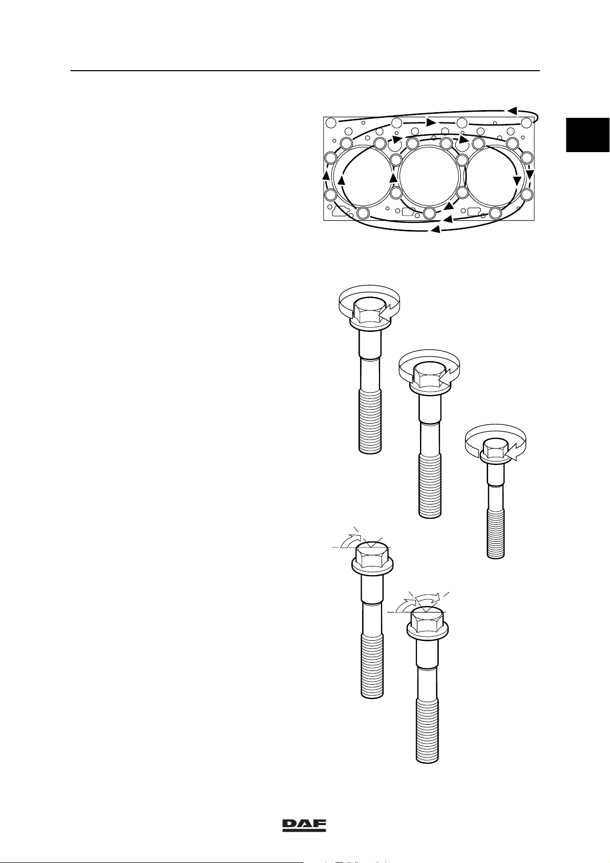
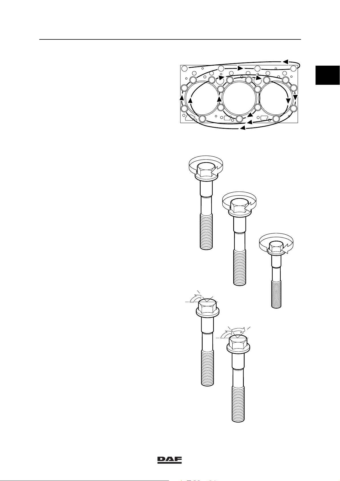
Cylinder head attachment bolts
Cylinder head bolts must only be used once .
So the cylinder head bolts should always be
replaced. The new cylinder head bolts have a
red/brown sealant on the thread.
Note:
- Because of the sealant used on the cylinder
head bolts, their untightening torque may be
very high!
- All M16 and M12 threaded holes must be
carefully cleaned with a screw tap before
the bolts are fitted.
- Once the bolts have been tightened to the
specified torque, the angular displacement
of the M16 bolts must immediately be
started.
- The sealant cannot be applied later.
Tightening cylinder head attachment bolts
16
15
21
17
11
10
50 Nm
18 19
17
6
5
4
20
8
2
3
12
13
14
9
M200562
0
Note:
Apply a drop of oil underneath the bolt heads
(on their abutting surface). Sealant also reduces
the frictional resistance, which means that no oil
must be applied to the thread.
st
phase
1
Tighten M16 in the order
indicated
2ndphase
Tighten M16 in the order
indicated
Tighten M12 in the order
indicated
3rdphase
M16 in the order
indicated
in two steps of 60_ angular
(1) Apply a drop of oil to bolts M16 and M12 on the
abutting surface of the bolt heads.
(1)
50 Nm
150 Nm
(1)
94 Nm
displacement
60
III
150 Nm
M16
I
M16
94 Nm
II
M12
II
M16
60
ǹ 200335
M16
III
M200563
2-7

TECHNICAL DATA
2
XF engine 95XF series
0
Timing gear
Camshaft locking plate attachment bolts 30 Nm
Attachment bolts, fuel pump drive shaft locking
plate
Timing case attachment bolts 30 Nm
Timing cover attachment bolts:
M10 attachment bolts 60 Nm
M8 attachment bolts 25 Nm
Timing cover protection plate attachment bolt 15 Nm
Camshaft gear attachment bolt 425 Nm
Idler gear attachment bolt 170 Nm
Attachment bolt, fuel pump gear wheel 260 Nm
Attachment bolt, silencer 30 Nm
Steering pump gear attachment nut 80 Nm
Steering pump intake pipe banjo bolt 90 Nm
Steering pump delivery pipe banjo bolt 40 Nm
Compressor gear attachment nut 120 Nm
(1) Secure with Loctite 243
30 Nm
(1)
(1)
(1)
(1)
(1)
(1)
2-8
ǹ 200335
2
TECHNICAL DATA
95XF series XF engine
Flywheel housing
Attachment bolts 110 Nm
Sealant to be used when fitting flywheel
housing
Flywheel
Attachment bolts
Without PTO 260 Nm
Without PTO spanner size 21 mm 260 Nm + 90_ angular displacement
With PTO 260 Nm + 150_ angular displacement
Engine mountings on timing gear end
Cylinder block bracket attachment bolts 92 Nm
Chassis engine bracket attachment bolts 73 Nm
Vibration damper engine bracket attachment
bolts
Engine mountings on flywheel end
Flywheel housing engine bracket attachment
bolts
Chassis engine bracket attachment bolts 73 Nm
Vibration damper engine bracket attachment
bolts
Loctite 510
225 Nm + 60_ angular displacement
260 Nm
225 Nm + 60_ angular displacement
(1)
(1)
+90_ angular displacement
0
Engine hanger brackets
Attachment bolts 110 Nm
Valve gear
Valve cover attachment bolts 25 Nm
Rocker setting bolt lock nut 40 Nm
Bridge piece setting bolt lock nut 40 Nm
Lubricating oil strip/rocker seat attachment
bolts
DEB set screw nut 25 Nm
Solenoid valve 20 Nm
Wiring harness attachment bolt 9 Nm
Valve sleeve attachment bolts 30 Nm
Tighten the valve sleeve bolts in the
sequence shown.
110 Nm
3
5
1
11
13
9157
2
6
814
41210
M200942
(1) Secure with Loctite 243
ǹ 200335
2-9

0
TECHNICAL DATA
XF engine 95XF series
2
2-10
ǹ 200335

2
TECHNICAL DATA
95XF series XF engine cooling system
3. XF ENGINE COOLING SYSTEM
3.1 GENERAL
Thermostat
Thermostat opening temperatures:
- thermostat opens at 83_C
- thermostat opened at least 12 mm at 95_C
Thermostat seat Loctite 638
Water pump
Maximum radial play 0.16 - 0.20 mm
Expansion tank pressure cap
Pressure relief valve opening pressure 0.75 bar
Underpressure valve opening pressure 0.1 bar
Pressure testing the cooling system
Test pressure 0.5 - 0.7 bar
0
ǹ 200335
3-1

TECHNICAL DATA
2
XF engine cooling system 95XF series
3.2 TIGHTENING TORQUES
0
The tightening torques stated in this section are
different from the standard tightening torques
stated in the overview of the standard tightening
torques. The other threaded connections which
are not stated must therefore be tightened to the
tightening torque stated in the overview of
standard tightening torques.
When attachment bolts and nuts are to be
replaced, it is important that they are of exactly
the same length and property class as the ones
removed unless stated otherwise.
Water pump
M8 attachment bolts 30 Nm
Threaded coupling 35 Nm
Coolant pipe
Attachment bolts 54 Nm
Coolant pipe threaded coupling 90 Nm
Coolant pipe plug 30 Nm
Thermostat housing
Attachment bolts 30 Nm
Plug 35 Nm
Radiator
Attachment nuts 70 Nm
3.3 FILLING CAPACITIES
Cooling system capacity approx. 50 litres
Cooling system capacity with ZF-intarder approx. 60 litres
3-2
ǹ 200335

2
TECHNICAL DATA
95XF series XF engine lubrication system
4. XF ENGINE LUBRICATION SYSTEM
4.1 GENERAL
Oil pressure
Oil pressure at engine idling speed 1 bar (warm engine)
Oil pressure at full-load engine speed 3,5 - 4.5 bar
Oil filter
Type disposable filter
Quantity 1
Installation in the oil circuit full flow
Opening pressure of bypass valve at a
pressure difference of
Oil cooler
Opening pressure of bypass valve at a
pressure difference of
Oil section test pressure 6 bar
2,5 0.3 bar
2 bar
0
ǹ 200335
4-1

TECHNICAL DATA
2
XF engine lubrication system 95XF series
4.2 TIGHTENING TORQUES
0
The tightening torques stated in this section are
different from the standard tightening torques
stated in the overview of the standard tightening
torques. The other threaded connections which
are not stated must therefore be tightened to the
tightening torque stated in the overview of
standard tightening torques.
When attachment bolts and nuts are to be
replaced, it is important that they are of exactly
the same length and property class as the ones
removed unless stated otherwise.
Fuel filter
Attachment bolts, fuel filter/water pipe
connection
Fuel pump filter head banjo bolt 40 Nm
Lubricating oil strip/rocker seats
Attachment bolts 110 Nm
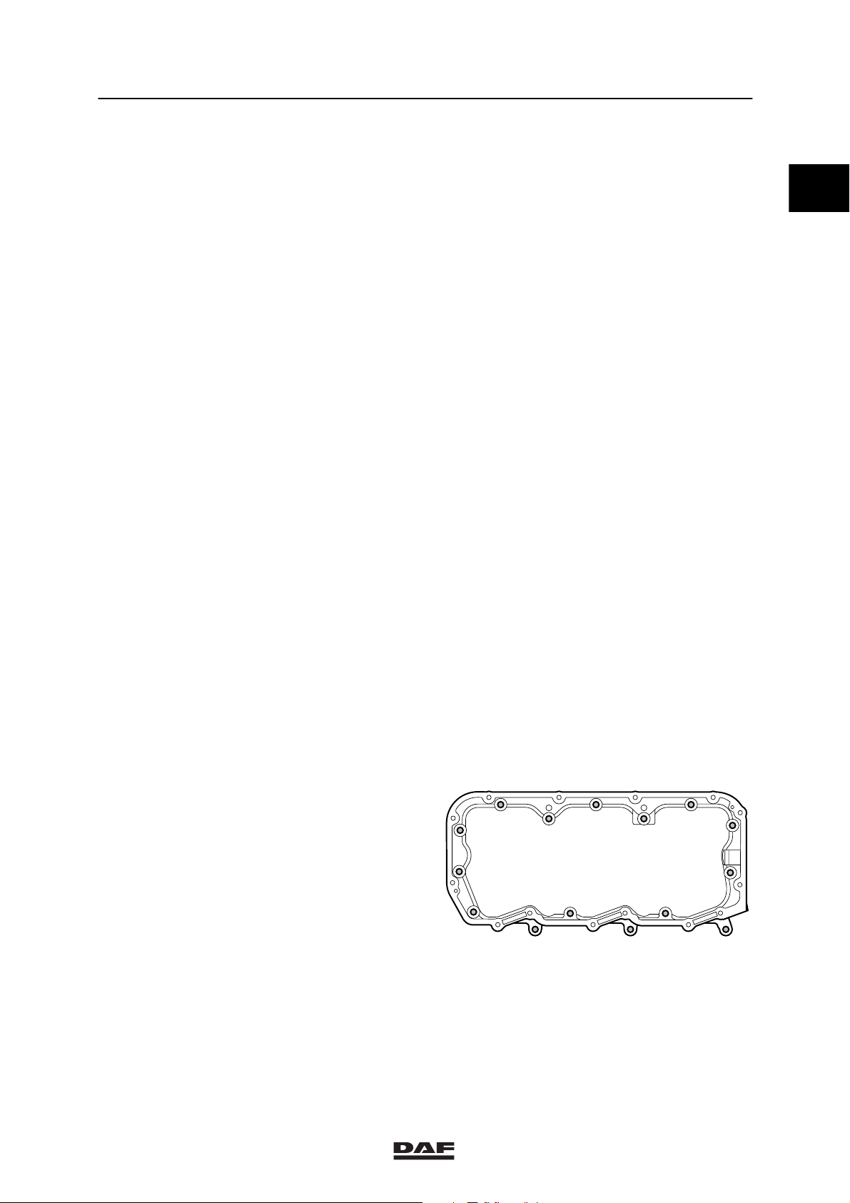
Oil sump
Clamp attachment bolts 25 Nm
Oil drain plug 60 Nm
Oil pump
Attachment bolts for oil pump housing sections 30 Nm
Attachment bolts connecting oil pump to main
bearing cap
Delivery pipe attachment bolts 30 Nm
Idler gear central bolt 60 Nm
40 Nm
60 Nm
(1)
(1)
(1)
Strainer
Bracket attachment bolts 30 Nm
Lubricating oil filter
Lubricating oil filter housing attachment bolts 50 Nm
Oil filter 45 Nm
Coupling in lubricating oil filter head 60 Nm
Bypass pressure regulator
Plug 80 Nm
(1)
(2)
(3)
4-2
ǹ 200335
2
TECHNICAL DATA
95XF series XF engine lubrication system
Oil cooler
Attachment bolts connecting oil cooler to
cylinder block
Coolant supply pipe union 90 Nm
Plug, adjustable banjo connection 90 Nm
Banjo bolt, adjustable banjo connection 90 Nm
Centrifugal oil filter
Central bolt 20 Nm
Oil discharge pipe union 50 Nm
Dip stick
Threaded coupling 60 Nm
(1) Secure with Loctite 243
(2) Secure with Loctite 572
(3) Secure with Loctite 2701
Oil sprayer
Banjo bolt M14 for oil sprayer with locking
plate
M10 banjo bolt for oil sprayer 30 Nm
50 Nm
30 Nm
0
Main bearing caps
Main bearing cap attachment bolts 150 Nm + 120_ angular displacement
Big-end bearing caps
Attachment bolts, big-end bearing caps
st
1
phase,
sequence 1-2-3-4
nd
phase,
2
sequence 4-3-2-1
rd
phase,
3
sequence 1-2-3-4
35 Nm
45 Nm
60_ angular
displacement
(2)
1 4
32
(1) Apply a drop of oil to thread and contact surface.
(2) Connecting rod bolts are to be used once and
tightened as instructed.
When fitting the connecting rod in the engine, apply a
drop of oil to the threads and contact surfaces of the
connecting rod bolts.
(1)
M200661
ǹ 200335
4-3

TECHNICAL DATA
XF engine lubrication system 95XF series
4.3 FILLING CAPACITIES
2
0
Lubrication system
Total capacity, including oil cooler and oil filter approx. 32 litres
Oil sump capacity, maximum level approx. 25 litres
Oil sump capacity, minimum level approx. 17 litres
4-4
ǹ 200335

2
TECHNICAL DATA
95XF series XE engine
5. XE ENGINE
5.1 GENERAL
Types XE 280 C
XE 315 C/C2
XE 355 C
XE 390 C
Version Euro 3 (C), (C2 = 4 öko), water-cooled,
four-stroke diesel engine with direct fuel
injection, 4-valves per cylinder and
turbo-intercooling.
Number of cylinders 6
Bore x stroke 130 x 158 mm
Swept volume 12.58 l
Compression ratio 16.0 : 1
Firing order 1-5-3-6-2-4
Weight approx. 1,080 kg
ENGINE TYPE
XE 280 C 280 at 2000 1750 at 1000 - 1500
XE 315 C/C2 315 at 2000 1900 at 1100 - 1500
P(kW)atrpm M(Nm)atrpm
0
XE 355 C 355 at 2000 2100 at 1100 - 1500
XE 390 C 390 at 1900 2350 at 1100 - 1500
ENGINE TYPE IDLING SPEED MAX. NO LOAD SPEED
XE 280 C 525 - 575 approx. 2300
XE 315 C/C2 525 - 575 approx. 2300
XE 355 C 525 - 575 approx. 2300
XE 390 C 525 - 575 approx. 2300
ǹ 200335
5-1

0
TECHNICAL DATA
2
XE engine 95XF series
V-BELT TENSION
Belt tension, “AVX” raw-edge
Multiple-V-belt Single-V-belt
Setting tension 1200 600
Test tension ≥800 ≥400
Minimum tension 500 250
Adjusting tension 700 350
(1) Raw-edge V-belts can be recognised by the absence
of textile fabric in the rubber, with the exception of the
top of the belt edge, on the edges and the insides of
the belt (polished belt edges). Version: either toothed
or non-toothed.
(2) After fitting the new V-belt, set the pre-tension to the
“setting tension” and after a trial run check whether the
pre-tension complies with the “test tension”. If the
tension reading is lower than the “test tension”
specified in the table, set the V-belt to the minimum
test tension.
1
V-belts in Newtons (N)
New V-belt
Worn V-belt
2
3
(3) If the V-belt tension is lower than the “minimum
tension”, set the belt to the “adjusting tension”.
Cylinder liner
Height above cylinder block 0.02 - 0.10 mm
Cylinder head
Minimum height after overhaul 119.50 mm
Test pressure using air (hot) 1.5 bar
Valve clearance
Valve clearance (cold/hot)
inlet 0.50 mm
exhaust 0.50 mm
Valve opening
Valve opening at 1 mm valve clearance 0.3 - 0.7 mm
M2121
5-2
ǹ 200335

2
TECHNICAL DATA
95XF series XE engine
Axial play
Crankshaft axial play 0.06 - 0.32 mm
Camshaft axial play 0.10 - 0.55 mm
Idler gear axial play 0.05 - 0.25 mm
Gear backlash
Idler gear - crankshaft gear 0.02 - 0.21 mm
Idler gear pump housing camshaft gear 0.02 - 0.22 mm
Idler gear - camshaft gear 0.02 - 0.21 mm
Camshaft gear - compressor gear 0.02 - 0.22 mm
Pump housing camshaft gear - steering pump
gear
Oil pump idler gear - oil pump gear 0.02 - 0.20 mm
Crankshaft gear - oil pump idler gear 0.02 - 0.20 mm
Number of teeth, timing gears
Crankshaft gear 35
Idler gear 54
Pump housing camshaft gear 70
Camshaft gear 70
Air compressor gear 27
Fan drive housing gear 29
Steering pump gear 18
Lubricating oil pump idler gear 34
0.02-0.19mm
0
Fan drive
Heat gear wheel for max. 30 min. 245_C
Compression pressure
Differences in compression pressure max. 15%
Flywheel/starter ring gear
Axial variation, measured at a radial distance
of 210 mm
Starter ring gear warm up max. 185_C
0.10 mm
ǹ 200335
5-3

TECHNICAL DATA
2
XE engine 95XF series
5.2 TIGHTENING TORQUES
0
The tightening torques stated in this section are
different from the standard tightening torques
stated in the overview of the standard tightening
torques. The other threaded connections which
are not stated must therefore be tightened to the
tightening torque stated in the overview of
standard tightening torques.
When attachment bolts and nuts are to be
replaced, it is important that they are of exactly
the same length and property class as the ones
removed unless stated otherwise.
Starter motor
Attachment nuts 73 Nm
Alternator
Alternator bracket attachment bolts 55 Nm
Alternator attachment bolts 50 Nm
Pulley attachment nut, version 55A 70 Nm
Pulley attachment nut, version 95A 70 Nm
Air compressor
M12 attachment bolts 110 Nm
M8 attachment bolts for bracket 30 Nm
M10 attachment bolts for bracket 60 Nm
Compressor gear flanged nut 120 Nm
M14 cylinder head threaded coupling 40 Nm
M26 cylinder head threaded coupling 90 Nm
Delivery pipe reducer valve 75 Nm
Suction and pressure line unions 90 Nm
(1)
Air-conditioning compressor
M12 attachment bolts for compressor bracket 110 Nm
M10 attachment bolts for compressor 60 Nm
Exhaust manifold
Fit gasket with steel side towards manifold
Sleeved attachment bolts 65 Nm
Heat shield attachment bolts 30 Nm
(1)
(1)
5-4
ǹ 200335

2
TECHNICAL DATA
95XF series XE engine
Inlet manifold
Attachment bolts 60 Nm
Glow plug attachment nut 55 Nm
Air inlet hose clamps 12 Nm
0
Turbocharger
Heat shield attachment bolts 30 Nm
Turbine housing clamp plate attachment nut 15 Nm
Attachment nuts
Exhaust manifold flange/turbocharger 60 Nm
Elbow on turbocharger 40 Nm
Oil supply pipe banjo bolt 90 Nm
(1) Apply Loctite 243 to secure
(2) Apply Copaslip to secure
(1)
(2)
ǹ 200335
5-5

0
TECHNICAL DATA
2
XE engine 95XF series
Vibration damper and fan drive
8
9
7
6
5
4
3
2
1
Vibration damper hub attachment bolts (1) in 4
phases:
st
1
phase, all attachment bolts 100 Nm
2ndphase, all attachment bolts 100 Nm
3rdphase, all attachment bolts 100 Nm
4thphase, all attachment bolts 100 Nm
Attachment bolts, vibration damper (5) 110 Nm
Attachment nuts, fan drive (8) 60 Nm
Attachment bolts, fan pulley (9) 30 Nm
Attachment nuts, fan clutch (7) 25 Nm
(1) Tighten the attachment bolts evenly
(2) Secure with Loctite 243
M200945
(1)
(1)
(1)
(1)
(2)
(2)
5-6
ǹ 200335
2
TECHNICAL DATA
95XF series XE engine
Cylinder head attachment bolts
Cylinder head bolts must only be used once.So
the cylinder head bolts should always be
replaced. The new cylinder head bolts have a
red/brown sealant on the thread.
Note:
- Because of the sealant used on the cylinder
head bolts, their untightening torque may be
very high!
- All M16 and M12 threaded holes must be
carefully cleaned with a screw tap before
the bolts are fitted.
- Once the bolts have been tightened to the
specified torque, the angular displacement
of the M16 bolts must immediately be
started.
- The sealant cannot be applied later.
Tightening cylinder head attachment bolts
16
15
21
17
11
10
50 Nm
18 19
17
6
5
4
20
8
2
3
12
13
14
9
M200562
0
Note:
Apply a drop of oil underneath the bolt heads
(on their abutting surface). Sealant also reduces
the frictional resistance, which means that no oil
must be applied to the thread.
st
phase
1
Tighten M16 in the
order indicated
2ndphase
Tighten M16 in the
order indicated
Tighten M12 in the
order indicated
3rdphase
M16 in the order
indicated in two stages of 60_ angular
(1) Apply a drop of oil to bolts M16 and M12 on the
abutting surface of the bolt heads.
(1)
50 Nm
150 Nm
(1)
94 Nm
displacement
60
III
150 Nm
M16
I
M16
94 Nm
II
M12
II
M16
60
ǹ 200335
M16
III
M200563
5-7

TECHNICAL DATA
2
XE engine 95XF series
0
Timing gear
Camshaft locking plate attachment bolts 30 Nm
Pump housing camshaft locking plate
attachment bolts
Timing case attachment bolts 25 Nm
Timing cover attachment bolts:
M10 attachment bolts 60 Nm
M8 attachment bolts 25 Nm
Timing cover protection plate attachment bolt 15 Nm
Camshaft gear attachment bolt 425 Nm
Idler gear attachment bolt 170 Nm
Pump housing camshaft gear attachment bolt 260 Nm
Compressor gear attachment nut 120 Nm
Steering pump gear attachment nut 80 Nm
Suction pipe banjo bolt 90 Nm
Delivery pipe banjo bolt 40 Nm
(1) Apply Loctite 243 to secure
30 Nm
(1)
(1)
(1)
(1)
(1)
5-8
ǹ 200335
 Loading...