

Page 1

S/M No. : DSC120BEF0
Service Manual
Model: DSC-34W70N
Release 1
HDTV Monitor
Chassis : SC-120
Specification
Power Requirement AC 120V, 60Hz
Power Consumption 210watts
General
Dimensions(W/H/D) 41”W x 26.2”H x 24.6”D
Weight 81Kg (178.61bs)
Antenna One 75ohm external input terminal for
UHF/VHF/Cable
Screen Size 34”(diagonal), 16:9 Aspect Ratio
Picture
Display Format DTV : 1080I @ 33.75KHz
NTSC/DVD : 480p @ 31.5KHz
Horizontal Resolution 800 Lines
Sound System Dolby Pro Logic
Sound
NTSC Audio Multi CH TV Stereo(MTS) /
Second Audio Program(SAP)
Audio Power 8W/ch (Main L/R), 5W/ch (Center)
Rear
RF Antenna Input
NTSC A/V In 2each (Video/L/R)
1each (S-Video/Video/L/R)
NTSC A/V Monitor Out 1each (Video/L/R)
Inputs/ HD Component In 1each (Y/Pb/Pr)
Output DVD Component In 1each (Y/Cb/Cr)
Surround Channel Out 1each (SL/SR)
Sub woofer Out 1each
Side
NTSC A/V In 1each (S-Video/Video/L/R)
Headphone 1each (L/R)
DAEWOO ELECTRONICS CO., LTD.
http: // svc.dwe.co.kr Nov. 2001
Page 2

- 1 -
1. Product Safety 2
2. Specifications 4
3. Remote Control Overview 5
4. Limited Warranty 6
5. Service Mode 7
6. General Adjustment 10
7. Special Adjustment (When replacing new circuits boards) 15
8. Troubleshooting Charts 16
9. Parts List 25
10. Circuit Diagram
10-1. Power Circuit 47
10-2. Main Circuit 48
10-3. Audio Circuit 49
10-4. 3D Comb Filter Circuit 50
10-5. Main Video Circuit 51
10-6. Sub Video Circuit 52
10-7. Scan Rate Converter Circuit 53
10-8. RGB Processor Circuit 54
10-9. AV Circuit 55
10-10. Union Circuit 56
10-11. Signal Flow Diagram 57
11. Exploded View 58
Page 3
1.
PRODUCT SAFETY SERVICING GUIDELINES FOR COLOR TELEVISION RECEIVERS
- 2 -
CAUTION : Do not attempt to modify this product in any way.
Unau-thorized modifications will not only void the warranty, but
may lead to your being liable for any resulting property damage
or user injury. Service work should be performed only after you
are thoroughly familiar with all of the following safety checks
and servicing guide-lines. To do otherwise, increases the risk of
potential hazards and injury to the user.
SAFETY CHECKS
After the original service problem has been corrected, a check
should be made of the following:
SUBJECT : FIRE & SHOCK HAZARD
1.Be sure that all components are positioned in such a way as
to avoid possibility of adjacent component shorts.
This is especially important on those chassis which are
transported to and from the repair shop.
2.Never release a repair unless all protective devices such as
insulators, barriers, covers, shields, strain relief, and other
hardware have been reinstalled per original design.
3.Soldering must be inspected to discover possible cold solder
joints, frayed leads, damaged insulation (including A.C. cord),
solder splashes or sharp solder points. Be certain to remove
all loose foreign particials.
4.Check for physical evidence of damage or deterioration to
parts and components, and replace if necessary follow
original layout, lead length and dress.
5.No leads or components should touch a receiving tube or a
resistor rated at 1 watt or more. Lead tension around
protruding metal surfaces must be avoided.
6.All critical components such as fuses, flameproof resistors,
capacitors, etc. must be replaced with exact factory types.
Do not use replacement components other than those
specified or make unrecommended circuit modifications.
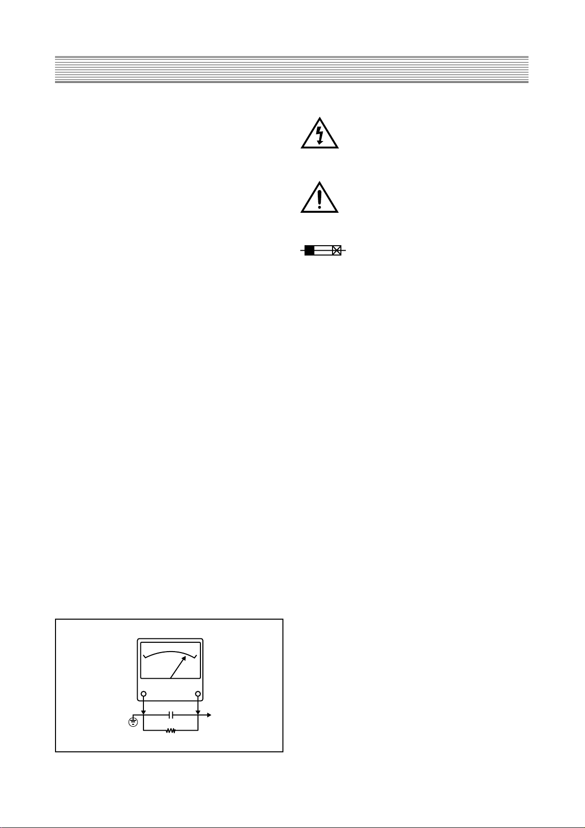
7.After re-assembly of the set always perform an A.C. leakage
test on all exposed metallic parts of the cabinet, (the channel
selector knob, antenna terminals, handle and screws) to be
sure the set is safe to operate without danger of electrical
shock. Do not use a line isolation transformer during this test.
Use an A.C. voltmeter, having 5000 ohms per volt or more
sensitivity, in the following manner : connect a 1500 ohm 10
watt resistor, paralleled by a 15 mfd. 150V A.C. type
capacitor between a known good earth ground (9water pipe,
conduit, etc.) and the exposed metallic parts, one at a time.
Measure the A.C. voltage across the combination of 1500
ohm resistor and 0.15 MFD capacitor. Reverse the A.C. plug
and repeat A.C. voltage measurements for each exposed
metallic part. Voltage measured must not exceed 0.75 volts
R.M.S. This corresponds to 0.5 milliamp A.C. Any value
exceeding this limit constitutes a potential shock hazard and
must be corrected immediately.
GRAPHIC SYMBOLS :
The lightning flash with arrowhead symbol,
within an equilateral triangle, is intended to
alert the service personnel to the presence of
uninsulated “dangerous voltage” that may be
of sufficiency magnitude to constitute a riskof
electric shock.
The exclamation point within an equilateral
triangle is intended to alert the service personnel to the presence of important safety
information in service literature.
Fuse symbol is printed on pcb adjacent to the
fuse, with “RISK OF FIRE REPLACE FUSE
AS MARKED”. The symbol is explained in the
service manual with the following wording or
equivalent.
CAUTION : FOR CONTINUED PROTECTION AGAINST
FIRE HAZARD, REPLACE ONLY WITH SAME TYPE (6.3A,
125V)” and
“
ATTENTION: AFIN D’ ASSU UNE PROTECTION
PERMANENTE CONTRE LES RISQUES D’ INCENDIE,
REMPLACER UNIQUE-MENT PAR UN FUSIBLE DE MEME
TYPE ET DE “6.3A, 125V”.
SUBJECT : X-RADIATION
1.Be sure procedures and instructions to all service
personnel cover the subject of X-rays in current T.V.
receivers is the picture tube. However, this tube does not
emit X-rays when the high voltage is at the factory
specified level. The proper value is given in the applicable schematic. Operation at higher voltages may cause
a failure of the picture tube or high voltage supply and,
under certain circumstances, may produce radiation in
excess of desirable levels.
2.Only factory specified C.R.T. anode connectors must be
used. Degaussing shields also serve as X-ray shield in
color sets. Always re-install them.
3.It is essential that the serviceman has available an
accurate and reliable high voltage meter. The calibration of
the meter should be checked periodically against a
reference standard. Such as the one available at your
distributor.
4.When the high voltage circuitry is operating properly there
is no possibility of an X-radiation problem. Every time a
color chassis is serviced, the brightness should be run up
and down while monitoring the high voltage with a meter to
be certain that the high voltage does not exceed the
specified value and that it is regulating correctly. We
suggest that you and your service organization review test
procedures so that voltage regulation is always checked
as a standard servicing procedure. And that the high
voltage reading be recorded on each customer’ s invoice.
5.When troubleshooting and making test measurements in a
receiver with a problem of excessive high voltage, avoid
being unnecessarily close to the picture tube and the high
voltage compartment. Do not operate the chassis longer
than is necessary to locate the cause of excessive voltage.
6.Refer to HV, B+ and Shutdown adjustment procedures
described in the appropriate schematic and
diagrams(where used).
AC VOLT METER
0.15 µF
1500 OHM
10 WATT
Good earth ground
such as a water
pipe, conduit, etc.
FIG 1
Place thes probe
on each exposed
metallic part
Page 4

- 3 -
SUBJECT : IMPLOSION
1.All direct viewed picture tubes are equipped with an
integral Implosion protection system, but care should be
taken to avoid damage during installation.
Avoid scratching the tube. If scratched, replace it.
2. Use only recommended factory replacement tubes.
SUBJECT : TIPS ON PROPER INSTALLATION
1.Never install any receiver in closed-in recess, cubbyhole or
Closely fitting shelf space over, or close to heat duct, or in
the path of heated air flow.
2.Avoid conditions of high humidity such as : Outdoor patio
Installations where dew is a factor. Near steam radiators
where steam leakage is a factor, etc.
3.Avoid placement where draperies may obstruct rear
venting. The customer should also avoid the use of
decorative scarves or other coverings which might obstruct
ventilation.
4.Wall and shelf mounted installations using a commercial
mounting kit, must follow the factory approved mounting
instructions. A receiver mounted to a shelf or platform
must retain its original feet(or the equivalent thickness in
spacers) to provide adequate are flow across the bottom,
bolts or screws used for fasteners must not touch and
parts or wiring. Perform leakage test on customized
installations.
5.Caution customers against the mounting of a receiver on
sloping shelf or a tilted position, unless the receiver is
properly secured.
6.A receiver on a roll-about cart should be stable on its
mounting to the cart. Caution the customer on the hazards
of trying to roll a cart with small casters across thresholds
or deep pile carpets.
7.Caution customers against the use of a cart or stand which
has not been listed by underwriters laboratories, inc. For
use with their specific model of television receiver or
generically approved for use with T.V.’ s of the same or
larger screen size.
Page 5

2. Specification
- 4 -
Power Requirement AC 120V, 60Hz
Power Consumption 210watts
General Dimensions(W/H/D) 41”W x 26.2”H x 24.6”D
Weight 81Kg (178.61bs)
Antenna One 75ohm external input terminal for
UHF/VHF/Cable
Screen Size 34”(diagonal), 16:9 Aspect Ratio
Picture Display Format DTV : 1080I @ 33.75KHz
NTSC/DVD : 480p @ 31.5KHz
Horizontal Resolution 800 Lines
Sound System Dolby Pro Logic
Sound NTSC Audio Multi CH TV Stereo(MTS) /
Second Audio Program(SAP)
Audio Power 8W/ch (Main L/R), 5W/ch (Center)
Rear
RF Antenna Input
NTSC A/V In 2each (Video/L/R)
1each (S-Video/Video/L/R)
NTSC A/V Monitor Out 1each (Video/L/R)
Inputs/ HD Component In 1each (Y/Pb/Pr)
Output DVD Component In 1each (Y/Cb/Cr)
Surround Channel Out 1each (SL/SR)
Sub woofer Out 1each
Side
NTSC A/V In 1each (S-Video/Video/L/R)
Headphone 1each (L/R)
Page 6
3. Remote control overview
- 5 -
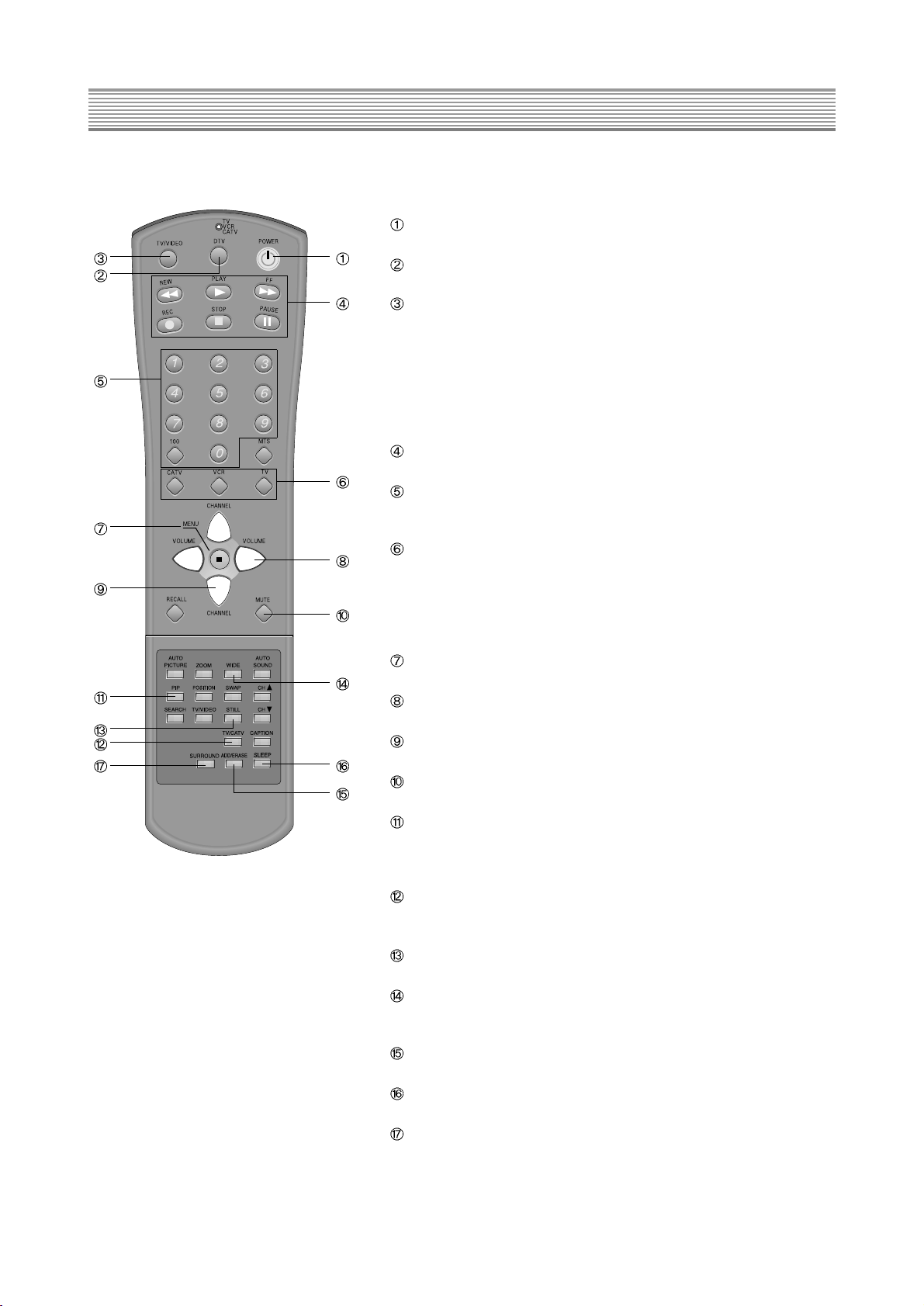
The remote control has the following functions:
Power button
Press to turn the HDTV Monitor (and other equipment) on and off
DTV button
Press this button repeatedly to display HD Component Video.
TV/VIDEO button
Press to view components you have connected to the HDTV Monitor.
Press this button repeatedly to display:
*TV mode
*Video1
*Video2
*Video3
*DVD
VCR Control Board
Basic VCR functions are operated with buttons on this board.
Direct Channel Selection Board
Pressing the numbers on this board, you can select program channels of
the screen directly.
Mode buttons
Press to select which equipment you wish your remote control to
operate:
*TV
*CATV (cable box)
*VCR
Menu button
You can adjust the picture, sound and many other functions.
Volume buttons
Press to raise and lower the volume on your HDTV Monitor.
Channel buttons
Press to select channels.
Mute button
Press to mute the HDTV Monitor sound.
PIP Search buttons
Simultaneous window selection is possible through buttons of this board,
and various layouts of the windows can be selected according to the
user’s need or desire.
TV/CATV button
This button is used to convert reception modes between aerial and
cable transmission systems.
STILL button
Press to pause the screen temporarily.
WIDE button
Press to convert the screen aspect ratio between 4:3 and 16:9 and vice
versa.
ADD/ERASE button
Press to operate channel memory functions.
SLEEP button
Press to operate set up time memory for an automatic turn off.
Surround button
Press to choose one of the “Pro Logic” modes.
Page 7

4. Limited Warranty
- 6 -
Daewoo Electronics Corporation of America Inc. (also known as DECA) warrants this product to be free from defects in
material and workmanship and agrees to remedy any such defect.
This warranty covers 3 years labor and 3 years parts from the date of original purchase.
This warranty applies only to product purchased from authorized DECA dealer and used within the boundaries of U.S.A.
This warranty does not apply to product that has been improperly installed, subjected to usage for which the product was
not designed, misused or abused, damaged during transportation, or which has been altered in any way that affects the
reliability or detracts from its performance.
How you get warranty service
Warranty service can only be provided by an authorized DECA service center. For the closest authorized service center
to you, please contact your Dealer. In order to receive warranty service you must provide the authorized service center
with a copy of proof of purchase, signifying the date of purchase and the name of the Dealer from whom you purchased
the product.
Statutory warranties
The purchase may have rights under existing provincial or federal laws, and where any terms of this warranty are
prohibited by such laws, they are deemed null and void, but the remainder of the warranty shall remain in effect.
If you require further assistance, please call:
1-800-DAEWOO-8
Page 8
5. Service Modes
- 7 -
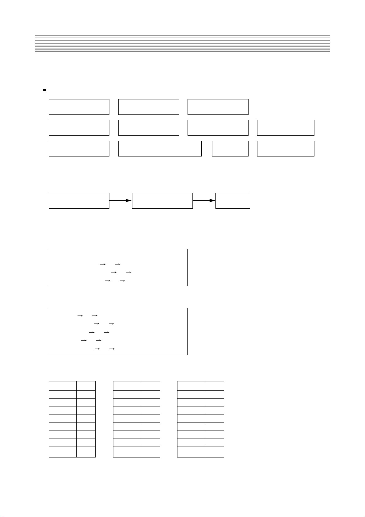
1.Entering to Service Mode
With the service remote control
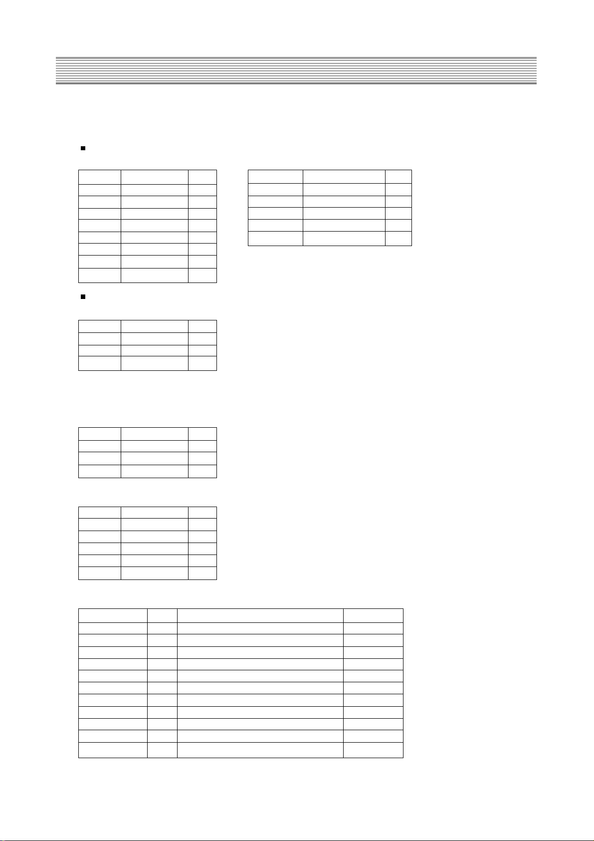
2. Function of each service mode
1) S1 : Heat Run mode.
2) S2 : Screen Voltage Control mode
The vertical deflection is down, and a horizontal line appears on the screen.
3) S3 : Sound Controls mode
4) S4 : Video Controls mode
5) S5 : Picture Quality Controls Mode : Fixed Data
S1 : Heat Run S2 : Screen Voltage
S3 : Sound Controls
S4 : Video Controls S5 : Picture Quality
S6 : Geometry S7 : PIP
S8 : White Balance
Auto power on mode Exit
S9 : Sub Picture & Sub Audio S10 : Option
S12 : Factory Setting
Full white mode
• Equalizer : 60Hz, 250Hz, 1KHz, 3.5KHz, 10KHz
• Main Volume : 0 63 31
• Balance control : -31 31 0
• Center Volume : 0 63 31
• Tint : 0 63 31
• Brightness : 0 48 24
• Contrast : 0
48 24
• Color : 0 63 31
• Sharpness : 0 63 31
LIM 1
SYS 3
AGI 0
DCO 1
CLP 0
CLM 0
ABM 0
ABT 3
HSE 0
• Don’t adjust above the mode, these are to adjust data of RGB Video Process IC (CXA2101).
FIX 0
VTC 0
HWI 0
HDT 0
HSM 0
CTI 3
LRG 15
GAM 15
PAB 0
BLK 0
SHP 3
PRE 3
LTI 0
VML 2
VMD 0
DCT 2
DPI 2
AKB 0
Page 9
Service Modes
- 8 -
6) S6 : Geometry Adjustment mode
NTSC/DVD
After receiving Air or external video, adjust geometry.
DTV
After connecting HD component at the DTV Input, adjust geometry.
7) S7: PIP Adjustment
• Press “PIP” button twice until the screen becomes two windows.
• Adjust below items so that the picture qualities of sub screen may be just the same with the main screen.
8) S8: White Balance Adjustment mode
9) S9 : Sub picture quality & Sub audio adjustment mode
HDUTY H Duty 16
HPOSI H Position 60
SPINW Side Pin W 24
SPIN Pincusion 48
HSIZE H Size 42
VSIZE V Size 73
VPOSI V Position 62
VSLIN V S Linearity 31
VCLIN V C Linearity 23
TRAPE Trapezoid 29
SPINS Side Pin S 33
FOCUSPH H Focus Phase 32
FOCUSPA H Focus Amplitude 32
MOIRE 16
VSMAX V Size Max 31
HPOSI H Position 67
HSIZE H Size 40
VSIZE V Size 63
VPOSI V Position 97
Brightness
+16
Contrast 48
Sharpness
64
Tint +0
RDRV Drive R 31
GDRV Drive G 31
BDRV Drive B 31
RCUT Cut off R 64
GCUT Cut off G 64
BCUT Cut off B 64
SUB-CONT 15 Sub Contrast available
SUB-BRIG 1 Sub Brightness available
SUB-SHP 3 Sub Sharpness available
SUB-COR 15 Sub Color available
SUB-TINT 15 Sub Tint available
PRE-FM 56 RF Audio Level Don’t adjust
PRE-SCART 25 Don’t adjust
PRE-SCART 1 38 Don’t adjust
NOR HP 20 The horizontal position of OSD available
DTV HP 10 The horizontal position of DTV OSD available
STEREO ID 32 Stereo detection sensitivity Don’t adjust
RF P-MUTE 3 When channel UP/DN, Video mute time available
Page 10
Service Modes
- 9 -
10) S10 : Option Adjustment mode
11) S12 : Factory Setting
3. Selecting the adjusting items
Pressing of Channel button changes the adjustment items. ( button for reverse order)
4. Adjusting the data
Pressing of VOLUME button changes the value of data. ( button for reverse order)
5. Exit from Service Mode
Press again to make service mode exit.
Caption English Fixed
CALMP 10 Don’t adjust
OSD POS 15 The horizontal position of Caption OSD available
EPOS 15
V POS 144 The Vertical position of Caption OSD available
POTION America / Korea Fixed
PC INPUT off Fixed
CIP-CT 27 The horizontal PLL speed of Video Process IC (VPC3230) Don’t adjust
CIP-BR 27 Don’t adjust
CIP-CR 22 Don’t adjust
CIP-CB 0 Don’t adjust
Dolby Ext off Dolby External L/R Mode Don’t adjust
CH 2
TV/VIDEO TV
TV/CABLE TV
Volume 20
Center Volume 0
PIP OFF
Equalizer Center
Auto Picture Standard
Auto Sound User
Wide 16:9
Zoom 16:9
Caption OFF
Child Lock OFF
Page 11

6. General Adjustment
- 10 -
In the majority of cases, a high definition digital television will need basic adjustments such as high voltage, screen
voltage, focus, white balance, sub brightness, and geometry. All adjustments should be performed after heat-running the
set for at least 20 minutes.
1. Press the S1 button on the service remote control, and then full white pattern will appear on the screen.
2. Press the S1 button twice, and then the pattern will disappear.
High Voltage Adjustment
1. Operate the set for at least 20 minutes.
2. Connect the probe of high voltage meter to CRT ANODE.
3. Adjust the variable register RV801 on the power assembly so that high voltage may be to be between
31.5KV ~ 32.5KV.
Screen Voltage Adjustment
1. Press the S2 button on the service remote control.
Vertical deflection will be down, and a horizontal line will appear on the screen.
2. Turn the variable screen volume of FBT to adjust screen voltage, at the point that a horizontal line only just appears.
Focus Adjustment
1. Tune on RETMA pattern.
2. Turn the variable focus volume of FBT so that the center area of screen is sharp scanning line.
3. Turn the variable volume R522 on the CRT assembly so that the edge of screen may be sharp scanning line.
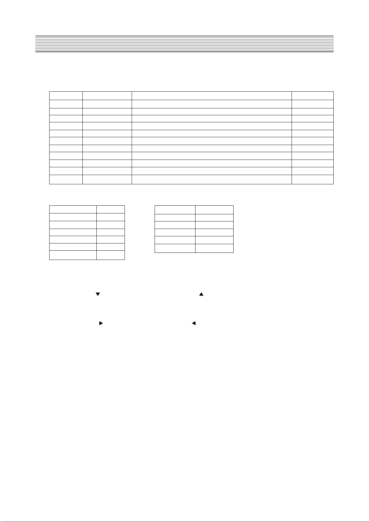
White Balance Adjustment
1. Input the Black & white signal to the HD Component jack on the rear panel.
<Black & White Pattern>
2. The color temperature is the following.
• x=0.270
0.005 y=0.270 0.005
• Color temperature : 13,214°K
3. Light Area Adjustment
1) Press S8 button.
2) On the center of light area, attach the sensor of a white balance meter.
3) To be Y=100, turn the Light Beam control volume on the White & Black pattern generator.
4) To adjust the white balance of light area, select Drive R, G, B with CHANNEL Up or Down buttons, and adjust
individual values with VOLUME Up or Down buttons.
4. Dark Area Adjustment
1) On the center of dark area, attach the sensor of a white balance meter.
2) To be Y=15, turn the Dark Beam control volume on the White & Black pattern generator.
3) To adjust the white balance of dark area, select Bias R, G, B with CHANNEL Up or Down buttons, and adjust
individual values with VOLUME Up or Down buttons.
4) Repeat two processes above until the white balance is completed.
Dark Area Check
Light Area Check
Page 12
General Adjustment
- 11 -
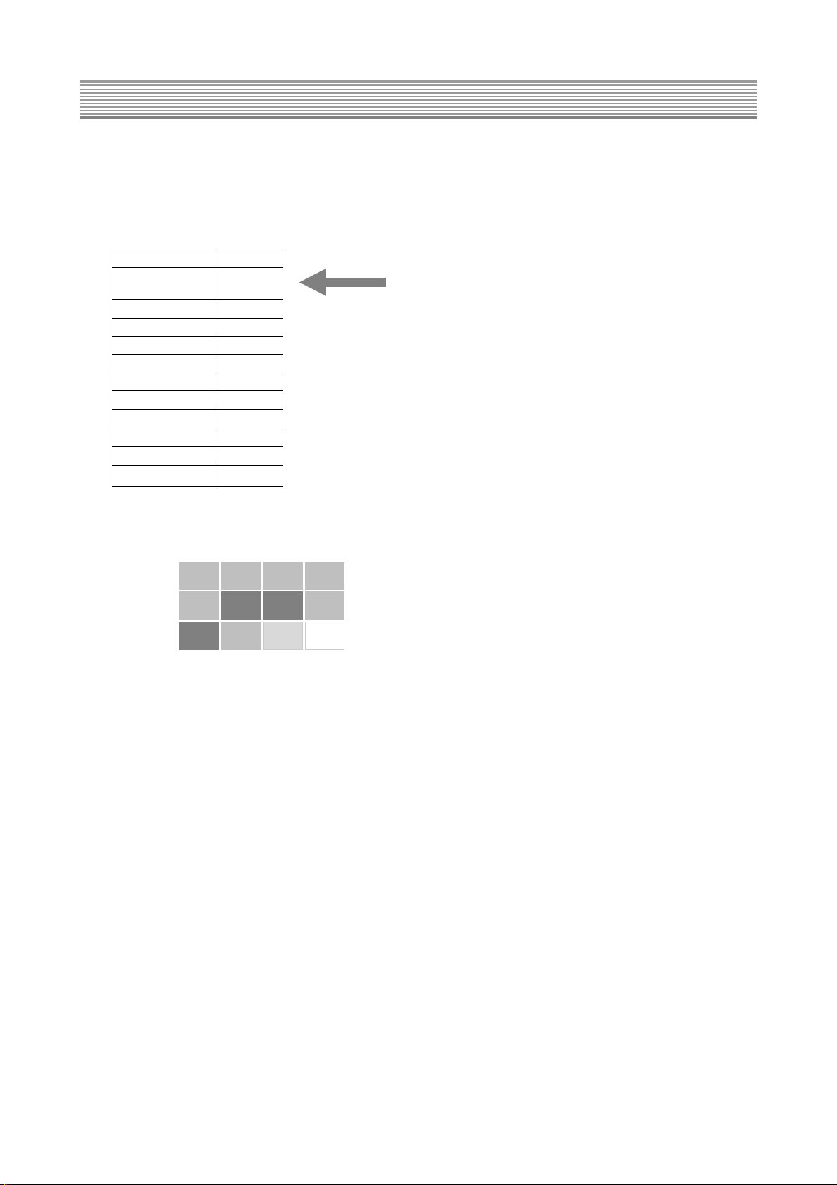
Sub Brightness Adjustment
1. Tune on RETMA Pattern.
2. Press S9 button.
3. The following OSD menu will appear on the screen, and the data are initial values before adjusting.
4. To be between Step 10% and 20% on the Contrast Chart, perform fine adjustment of sub brightness.
SUB-CONT 15
SUB-BRIG 1
SUB-SHP 3
SUB-COR 15
SUB-TINT 15
PRE-FM 56
PRE-SCART 25
PRE-SCART1 38
NOR HP 20
DTV HP 10
STEREO ID 32
RF P-MUTE 3
40% 30% 20% 10%
50% 0% 0% 5%
60% 70% 80% 100%
Page 13
General Adjustment
- 12 -
Geometry
1. To adjust V-Position, H-Size, H-Position and so forth, tune on RETMA Pattern.
2. To adjust Pincushion, Trapezoid and so forth, tune on Cross Hatch signal.
3. Screen Mode should be on 16:9 mode, and the Video Mode should be on Normal mode.
4. Press S6 button to adjust Geometry.
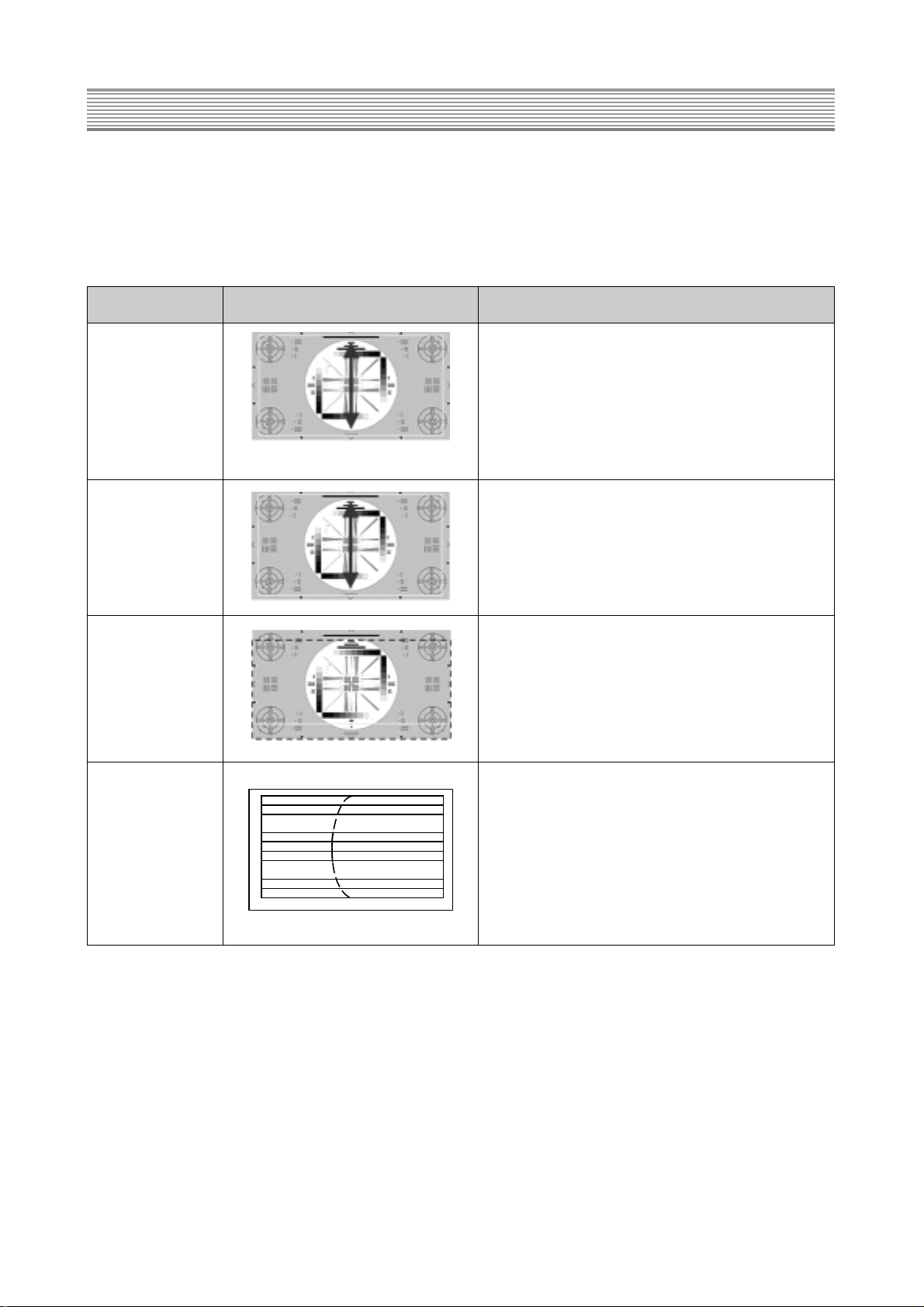
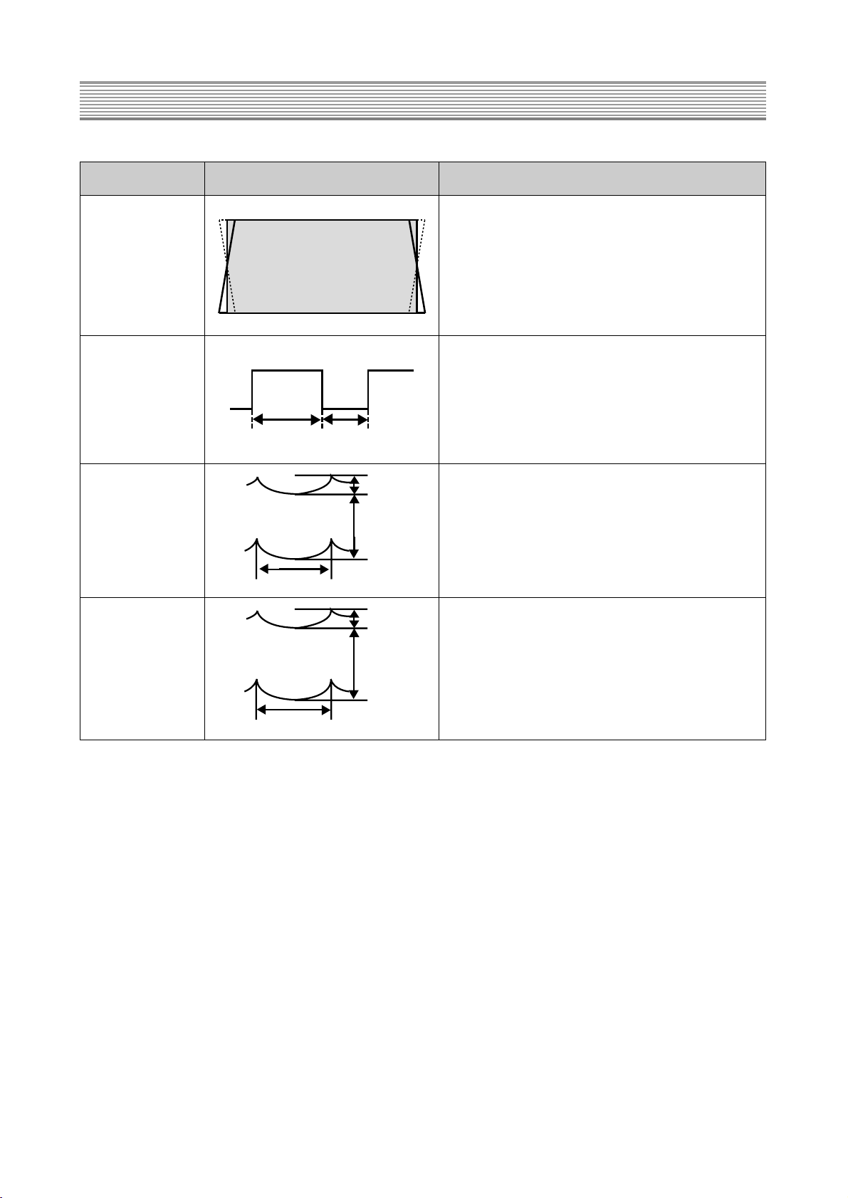
Item Screen Image Adjustmant Procedure
1) Receive NTSC RETMA signal.
2) The Screen mode should be selected on 16:9
mode
V Size Max. 3) Adjust Vertical Size so that over scanning rate may
be 105%.
4) Check if the center circle is not only circular on 16:9
mode but also on 4:3 mode.
Over Scanning Rate: 105%
1) There is no need to adjust.
2) Check if the value of data is “0”.
Vertical
Size
1) Receive NTSC RETMA signal.
2) The Screen mode should be selected
on 16:9 mode.
Vertical Adjust Vertical Position so that the circle of
Position RETMA signal may be centered in the vertical
direction.
1) Receive NTSC RETMA signal.
2) The Screen mode should be selected
V C Linearity on 16:9 mode.
3) When the center area of RETMA signal’s circle is
C type in the vertical direction, adjust VC
Linearity so that vertical interval may be the same.
Page 14
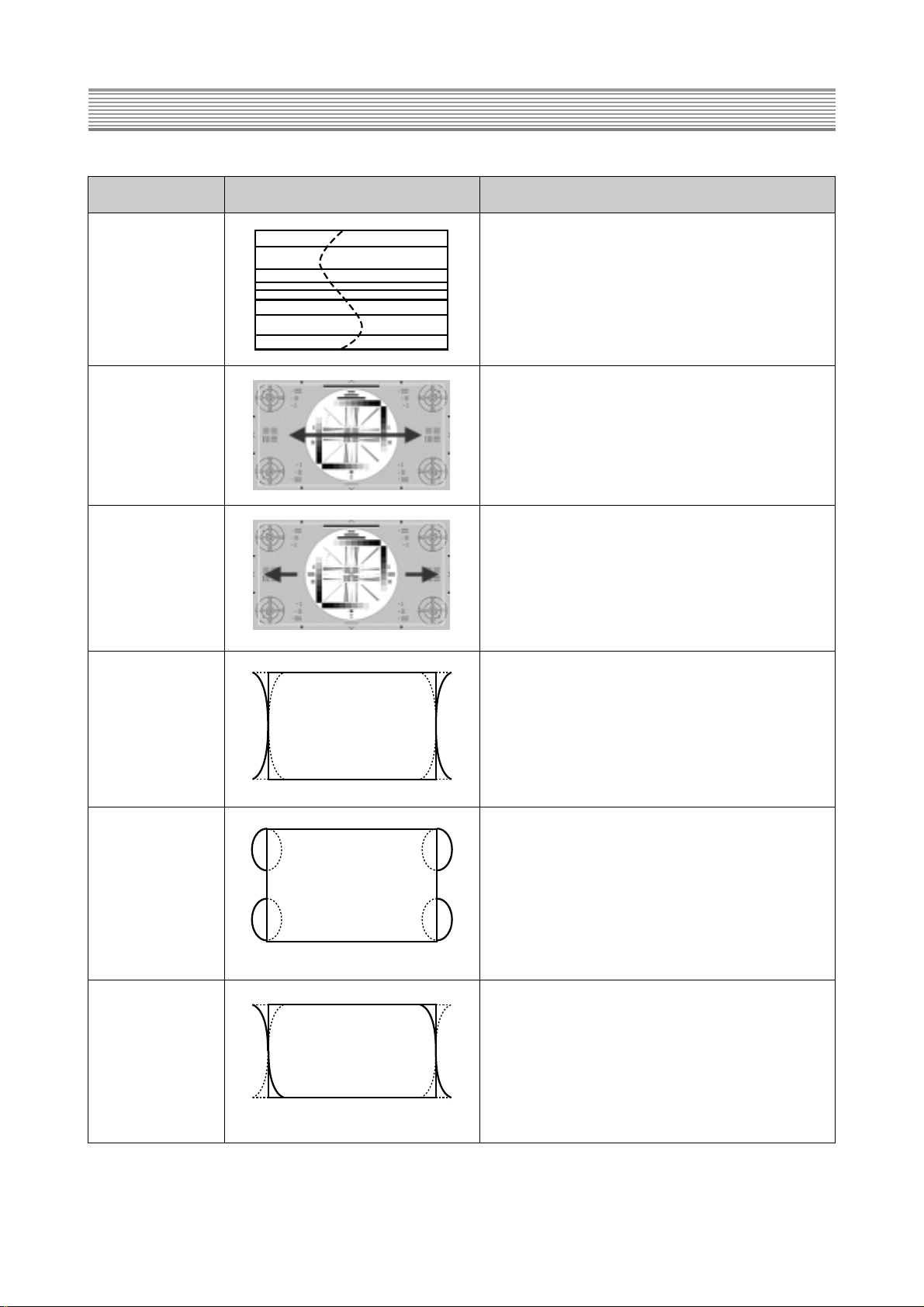
Item Screen Image Adjustmant Procedure
1) Receive NTSC RETMA signal.
2) The Screen mode should be selected on 16:9
V S Linearity mode.
3) When the center area of RETMA signal’s circle is
S type in the vertical direction, adjust VS
Linearity so that vertical interval may be the
same.
1) Receive NTSC RETMA signal.
2) The Screen mode should be selected on 16:9
mode
Adjust Horizontal Size for over scanning rate
Horizontal Size 106%. Check if the center circle of RETMA signal
is circle on Normal mode.
1) Receive NTSC RETMA signal.
2) The Screen mode should be selected on 16:9 mode
Horizontal 3) Adjust Horizontal Position so that the circle of
Position RETMA signal may be centered in the horizontal
direction.
1) Receive NTSC Cross Hatch signal.
2) The Screen mode should be selected on 16:9
mode.
Pincushion 3) When the vertical lines of the left and right side
are distorted such as the left figure, adjust
Pincushion so that the vertical lines may be
straight.
1) Receive NTSC Cross Hatch signal.
2) The Screen mode should be selected on 16:9
mode.
Side Pin W 3) When the vertical lines of the left and right side
are not straight but distorted in the W type, adjust
Side Pin W to correct the unbalanced vertical
lines.
1) Receive NTSC Cross Hatch signal.
2) The Screen mode should be selected on 16:9
Side Pin S mode.
3) When vertical lines of the left and right side is not
straight but distorted in the S type, adjust Side Pin
S to correct the unbalanced vertical lines.
General Adjustment
- 13 -
Page 15
General Adjustment
- 14 -
Item Screen Image Adjustmant Procedure
1) Receive NTSC Cross Hatch signal.
2) The Screen mode should be selected on 16:9
mode.
Trapezoid 3) When the screen shape is not rectangular but
trapezoid, adjust Trapezoid to correct the
unbalanced shape.
1) There is no need to adjust.
H Duty 2) Check if the value of data is “16”.
1) There is no need to adjust, and check if the value
of data is “32”.
H Focus Phase 2) Check that the focus on the right and left side is
clear.
1) There is no need to adjust, and check if the value
H Focus of data is “32”.
Amplitude 2) Check if the focus on the right and left side is clear.
400Vp-p
900Vp-p
60Hz
400Vp-p
900Vp-p
60Hz
Page 16

7. Special Adjustment
(When replacing new circuit boards)
- 15 -
1. Power assembly
1) After replacing a new assembly, X Radiation Protection Circuit Test
When service has been performed on the horizontal deflection system, high voltage system or B+ system, the
X-Radiation Protection Circuit Test must be tested for proper operation as follows:
1-1) Operate the HDTV Monitor for at least 20 minutes.
1-2) Perform this test at the normal video and sound.
1-3) Check the cathode voltage of D837. Its voltage should be about 25VDC.
1-4) Connect a resister 24K(1/4W) with parallel to R873.
1-5) Then the set will be shut down, lighting up red to the power indicator.
1-6) If it is not, the circuit of X-Radiation Protection must be repaired before the set is returned to the
customer.
2) The rest adjustment idem are no need to adjust.
2. Main assembly
1) After replacing a new assembly, the rest adjustments are no need.
3. Video assembly
1) No need to adjust.
Page 17
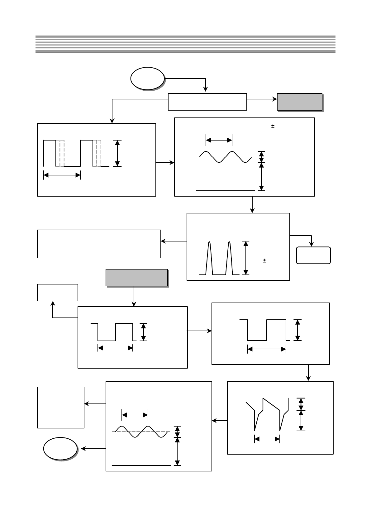
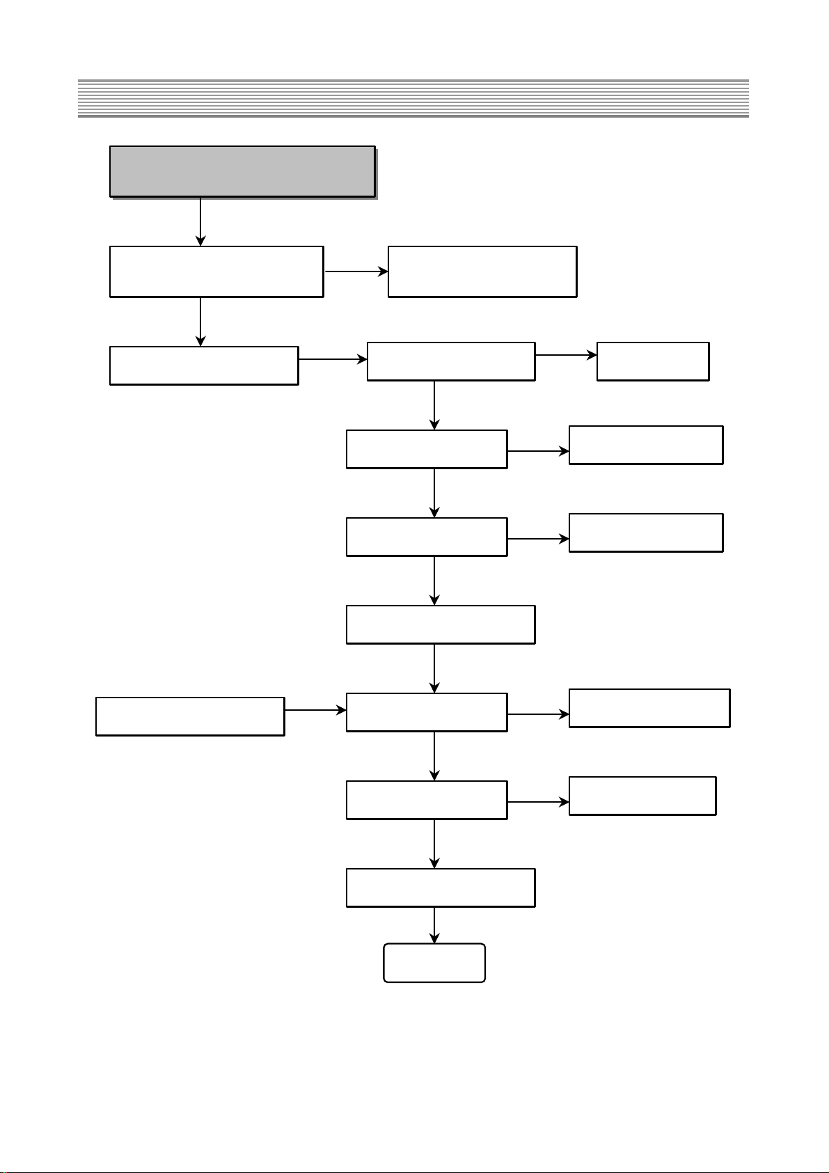
8. Troubleshooting charts
- 16 -
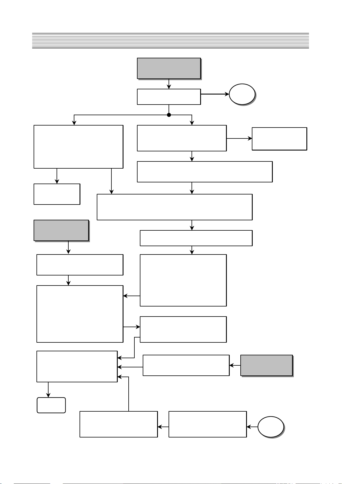
No Picture
(NTSC Signal)
OSD is on the screen.
Check OSD signal of I701.
R/G/B OSD : #64, 63, and 62
BL OSD : #61
Check OSD signal of UC107.
R/G/B OSD : #50, 51, and 52
BL OSD : #49
Check video signal of IA1.
Video1 :CVBS to #43, Y to #45,
and C to #47
Video2 :CVBS to #1
Video3 :CVBS to #7, Y to #9,
and C to #11
Check each
input signal.
When CVBS input, CVBS is to #34 of IA1.
When Y/C input, Y/C is to #37 and #39 of IA1.
When CVBS input, CVBS is to #88 of UC100.
Y/C signal of 3D comb filter is to #84 and #83 of UC100.
When Y/C input, Y/C is to #88 and #96 of UC100.
Y/C signal is to #73 and #71 of IC UC104.
Check below signal of UC104
-Y and C signal : #73, #71
-Picture Bus Y(MY0~MY7)
-Picture Bus C (MC0~MC7)
-V sync pulse (VSM) : #57
-Active video output (AVO) : #54
-Clock out (LLC2) : #27
Check below signal of UC106
-Picture Bus Y(MY0~MY7)
-Picture Bus C (MC0~MC7)
-V sync pulse (VSM) : #26
-Active video output (AVO) : #27
-Clock out (LLC2) : #18
-Y /Cb /Cr out: #87, 84, and 90
-H/V sync : #4, 5
Check below signal of UC107
R/G/B out : #35, 37, and 39
Check TV video signal of IA1.
CVBS of main tuner (TU01) : #41
CVBS of sub tuner (TU02) : #27
Check DVD signal to UC104.
Y/Cb/Cr : #5, 4, and 3
Check Tuner
(TU01 & TU02).
No Picture
(DVD Signal)
Check below signal of UC107
Y/Cb/Cr in : #69, 68 and 67
H/V sync : #66, 65
No Picture
(DTV Signal)
Check DTV signal of UC107
Y/Pb/Pr in : #5, 4 and 3
OSD
OSD
END
AV Signal RF Signal
NO
NO
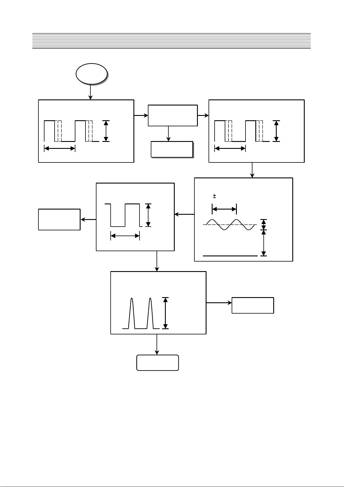
Page 18
Troubleshooting charts
- 17 -
No Sound
(NTSC Signal)
Check audio signal of IA1.
Video1 : L to #44, R to #46
Video2 : L to #2, R to #4
Video3 : L to #8, R to #10
AV Signal
RF Signal
Check the audio base-band signal to SIF of TU01.
Check audio signal of UC102.
-SIF to #67 -RF main L/R to #36, 37
Check audio signal of IA1.
-RF main L/R to #9, 11
-RF sub Mono to #25, 26
Check audio signal of IA1.
-Main L/R to #33, 32
-Sub L/R to #18, 16 (for the sub picture of PIP)
Check audio signal of UC102.
-Main L/R to #47, 48
(for RF and external audio 1,2,3)
-Sub L/R to #56, 57 (for Headphone L/R out)
Check DTV L/R of UC102.
-L/R to #53, 54
No Sound
(DTV Signal)
Check L/R out of UC102.
L/R/C to #28, and 27
Check C out of UC103
C to #34
Check SL/SR/Woofer out of UC102.
SL/SR/W to #25, 24, and 27
Check Headphone L/R out of UC102.
L/R to #34 and 33
Check the volume control of
headphone to IA4.
Check audio Amp (I601).
L/R/C In to #1, 2, and 4
L/R/C Out to #12, 11, and 8
Check DVDL/R of UC102.
-L/R to #50, 51
No Sound
(DVD Signal)
END
Check Headphone L/R out of IA03
L/R to #7 and 1
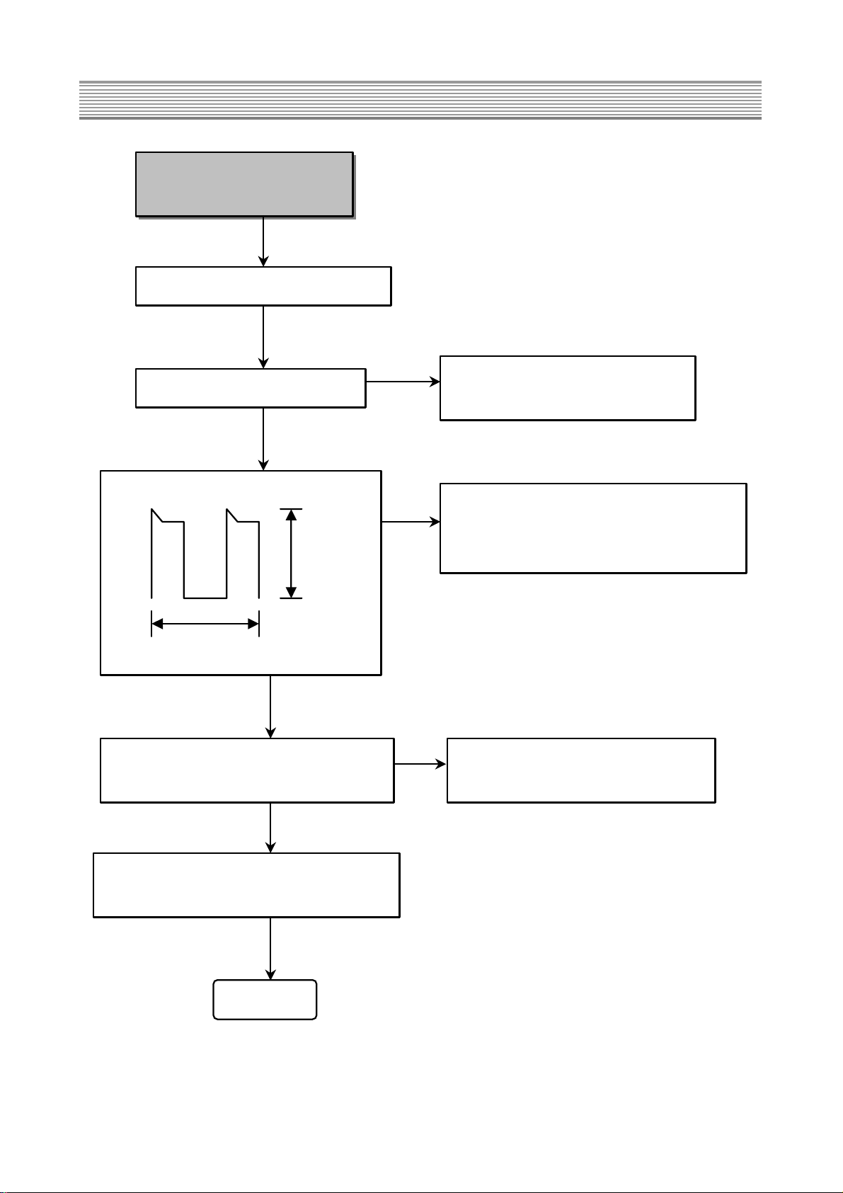
Page 19
Troubleshooting charts
- 18 -
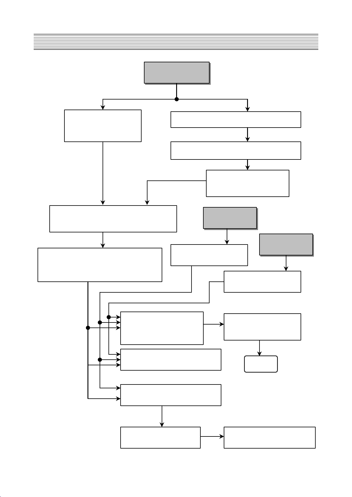
No Raster
NO
I701 communicates with I402 on the IIC bus.
Check the #3 (SDA) and #4 (SCL) of I402.
5Vp-p
Check I701
and I402.
Vertical
Deflection
Check #17 (H-Drive output) of I402.
0.7Vp-p
31.5KHz (NTSC/DVD)
33.75KHz (DTV)
Horizontal
Deflection
High Voltage
Drive
Check H Drive signal to emitter of Q411.
12Vp-p
31.5KHz (NTSC/DVD)
33.75KHz (DTV)
Check
Q416, Q417
H Drive signal is output to pin 3 of I407.
12Vp-p
33.75KHz
Check # 9
(E/W ) of
IC402.
NO
H/D1
Trigger pulse is input to #2 of I407.
31.5KHz (NTSC/DVD)
33.75KHz (DTV)
2Vp-p
6Vp-p
The control voltage of H Drive is
input to #5 of I407.
60Hz
0.5Vp-p
7Vp-p
NO
NO
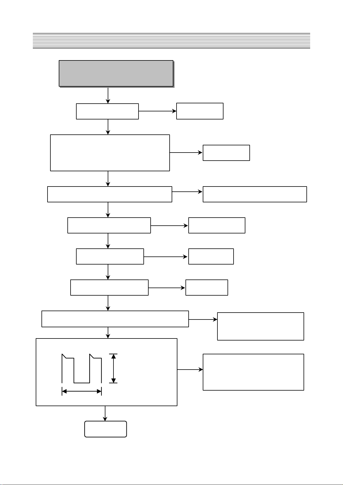
Page 20
Troubleshooting charts
- 19 -
H/D1
60Hz
5Vp-p
90V
Horizontal Drive B+ to R481 is 90V 5Vp-p
If the impedance value of Q425's collector
is near zero Ω, the horizontal deflection TR
(Q425) is dead. Replace Q425.
NO
END
Check 200VA to PA14M. To No Power
NO
H Drive signal is output to Source of Q423.
200Vp-p
31.5 / 33.75KHz
The voltage waveform of Q425's
Collector is the following.
1,300 50Vp-p
High Voltage Drive
Check H Drive signal to emitter of Q402.
12Vp-p
33.75KHz
Check I403
and high
voltage
feedback
circuits.
NO
HVD1
Check pin 17 (H-Drive output) of I402.
0.7Vp-p
31.5 / 33.75KHz
Check I402
Trigger pulse is input to pin 2 of I401.
31.5 / 33.75KHz
2Vp-p
6Vp-p
60Hz
0.25Vp-p
7Vp-p
The control voltage of high voltage
feedback is input to #5 of I401
NO
Page 21
Troubleshooting charts
- 20 -
HVD1
High Voltage Drive signal is output
to pin 3 of I401.
31.5 / 33.75KHz
12Vp-p
Check 200VB to
PA14M.
To No Power
NO
High Voltage Drive signal is output
to source of Q407.
31.5 / 33.75KHz
200Vp-p
60Hz
20Vp-p
100V
FBT B+ to #12 of PW16P is about
100V
20Vp-p
END
Check emitter
of Q401.
NO
Check Q810.
Check EHT Drive signal to
base of Q808.
31.5 /33.75KHz
12Vp-p
The voltage waveform of Q810's
drain is the following.
650Vp-p
Page 22

Troubleshooting charts
- 21 -
Vertical Deflection
Check I412.
NO
Vertical SAW waveform is to pin 8 of I412.
2.2Vp-p
60Hz
The following waveform is to pin 1 of I412.
3.5Vp-p
0V
NO
Check vertical deflection circuits
around I412.
Check vertical deflection circuits
around I412.
NO
END
Vertical deflection waveform is to pin 5 of I412.
50Vp-p
60Hz
Page 23
Troubleshooting charts
- 22 -
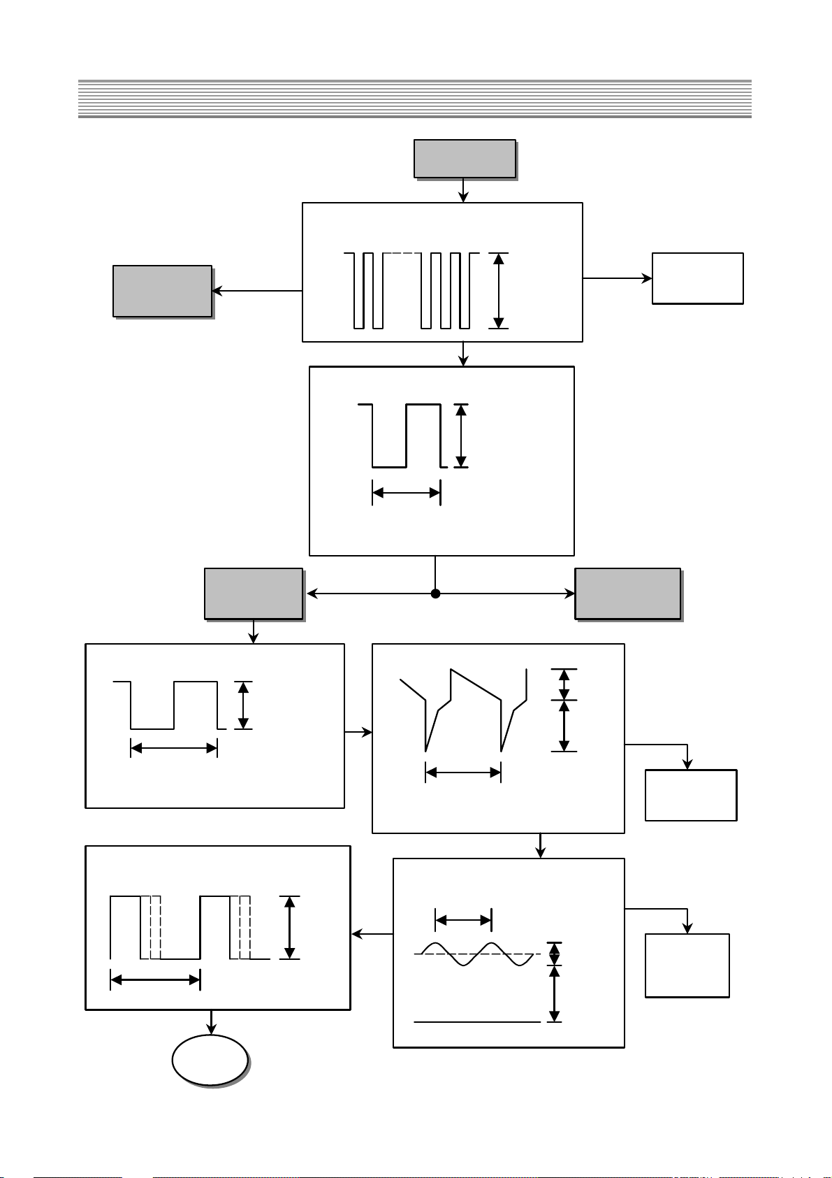
No Power
(Standby Power : I801)
The Standby LED doesn't light up red.
Approximately 150VDC is to C806.
NO
Check if F801 is open.
Check D801 (bridge rectifier).
Check if voltages to PW15 is supplied to TV
micro-processor(I701).
Check the parts caused a short-circuit to
secondary circuits.
NO
Check the impedance value of between Source
and Drain to I801. If the value is near zero Ω,
I801 is dead. Replace I801.
The following waveform is to drain of I801.
320Vp-p
100KHz
NO
When pressing Power button, the color of Power
LED is green
END
Page 24
Troubleshooting charts
- 23 -
No Power
Switch relay (Y802) doesn't operate.
NO
F801 short-circuits.
Replace F801.
Bridge rectifier (D805) short-circuits.
(The voltage of between Anode and Cathode to
D805 is 0.6V).
Replace D805.
Both AC lines of power cord don't short-circuit. Replace the parts caused a short-circuit.
PWR SW of PW15 is High. Check # 14 of I701.
Q804 doesn't defective. Replace Q804.
Check Y802 (switch relay).
Check the parts caused a short-circuit to secondary circuits
Replace defective parts with a
new one.
NO
NO
NO
NO
NO
NO
ReplaceY802.
The following waveform is to pin 1 of I803 and I805.
370Vp-p
50~80KHz
Check the primary circuits of SMPS
IC, and replace defective parts with a
new one.
NO
END
Page 25
Troubleshooting charts
- 24 -
NO Power
Switch relay operation (Y802) is OK.
Check the parts caused a shortcircuit to secondary circuits.
Replace defective parts with
a new one.
NO
Supply 200VA to PW14.
R802 is OK. ReplaceR802.
NO
NO
R807 and R852 are OK.
Replace R807 or R852.
NO
Q801, D810 are OK.
Replace Q801, D810.
NO
Check I803.
Supply 200VB to PA14M.
R823 and R853 are OK.
Replace R823 or R853.
NO
NO
Q802, D815 are OK.
Replace Q802, D815.
NO
Check I805.
END
Page 26
9. Part List (DSC-34W70N)
- 25 -
ZZ100 49B00R37E- TRANSMITTER REMOCON R-37D08
ZZ120 PEBCSHD013 COVER BACK AS DSC-3670W
M211 4952100800 COVER BACK FR HIPS PAINT
M353 4853526600 HOLDER CORD NYLON6(DACB-183)
M353A 7172401612 SCREW TAPPTITE TT2 TRS 4X16 MFZN BK
M541 4855415800 SPEC PLATE 150ART P/E FILM (C/TV)
M781 4857817610 CLOTH BLACK FELT 300X20X0.7
ZZ121 PEACPWD017 ACCESSORY AS DSC-3670N
10 495861200 MANUAL INSTRUCTION DSC-3670N
20 4850Q01210 BATTERY LR03 AAA ALKALINE
30 4858213800 BAG INSTRUCTION L.D.P.E T0.05X250X400
40 4850A01650 TRANS ANT MATCHING YSC-MTC-030
ZZ130 PEPKCPD013 PACKING AS DSC-3670W
M641 6520010100 STAPLE PIN AUTO W65
M681 4856812400 BAND 18MM X 3M
M801 4958000400 BOX CARTON DW-4
M811 4958100700 PAD EPS
M821 4958200600 BAG P.E T0.5X1900X1550
M841 4958400100 BOX STOPPER PP
M842 4958400200 EDGE HARD BOARD 5T 50X50X760
ZZ131 49519A0010 CRT GROUND NET DSC-3670N
ZZ132 58GD000002 COIL TILT DSC-3670N
ZZ133 58GD000001 COIL DEGAUSSING DC-36FL
ZZ140 PECACAD017 CABINET AS DSC-3670N
M201A 4956000100 SCREW CRT FIX SWRM10A L=35
M201B 4856215404 WASHER RUBBER CR T4.0
M201D 4857817630 CLOTH BLACK FELT 400X20X0.7
M201E 4857817610 CLOTH BLACK FELT 300X20X0.7
M201F 4953400600 BRKT CRT FR HIPS
M211A 7172401612 SCREW TAPPTITE TT2 TRS 4X16 MFZN BK
M211B 7172401612 SCREW TAPPTITE TT2 TRS 4X16 MFZN BK
M211C 7172401612 SCREW TAPPTITE TT2 TRS 4X16 MFZN BK
M211D 7172401612 SCREW TAPPTITE TT2 TRS 4X16 MFZN BK
M211E 7172401612 SCREW TAPPTITE TT2 TRS 4X16 MFZN BK
M231B 7172401612 SCREW TAPPTITE TT2 TRS 4X16 MFZN BK
M491A 7178301212 SCREW TAPPTITE TT2 WAS 3X12 MFZN BLACK
M492 4954900900 BUTTON POWER ABS BK
M492A 4856716000 SPRING SWPA PIE0.5
M551A 7178301212 SCREW TAPPTITE TT2 WAS 3X12 MFZN BLACK
M561 4955600100 MARK BRAND AL T1.0 DIA-CUTTING
M682 4856816300 CLAMP WIRE NYLON 6 (V0)
V901 4959600270 CRT W86LQQ350X97
V901A 4950704008 CONNECTOR TBL-P04H-A1+208T-1100=600
V901B 4950703008 CONNECTOR YH025-03+YST250+ULW=300
ZZ200 PEFMSJD013 MASK FRONT AS DSC-3670W
M201 4952000900 MASK FRONT FR HIPS PAINT
M331 4853311700 BRACKET BACK FR HIPS BK
S601 4958300310 SPEAKER AS L 10W 8 OHM K128/101999B
S601A 7172401612 SCREW TAPPTITE TT2 TRS 4X16 MFZN BK
S602 4958300110 SPEAKER UNIT 5W 8OHM H114/100400A
S602A 7178301212 SCREW TAPPTITE TT2 WAS 3X12 MFZN BLACK
S603 4958300210 SPEAKER AS R 10W 8 OHM K128/101999B
S603A 7172401612 SCREW TAPPTITE TT2 TRS 4X16 MFZN BK
ZZ230 PEPWMSD017 PCB POWER MANUAL AS DSC-3670N
C800 DDSA452T05 VARISTOR DSA-622M-U05A
C802 CL1JB3474K C LINE ACROSS AC250V 0.47MF U/C/SNDF/SV
C803 CL1JB3474K C LINE ACROSS AC250V 0.47MF U/C/SNDF/SV
C814 CEYN2G561P C ELECTRO 400V LHS 560MF (35X45)
C815 CEYN2G561P C ELECTRO 400V LHS 560MF (35X45)
C851 CEXF2E101V C ELECTRO 250V RSS 100MF 16X31.5
C852 CEXF2C101V C ELECTRO 160V RSS 100MF (16X25) TP
C854 CEYF1V222C C ELECTRO 35V RUS 2200MF (16X31.5)
C859 CEYF1V222C C ELECTRO 35V RUS 2200MF (16X31.5)
C864 CEXF2E101V C ELECTRO 250V RSS 100MF 16X31.5
C879 CMXF2G104J C MYLAR MPP 400V 0.1MF J
C880 CMYH3C472J C MYLAR 1.6KV BUP 4700PF J
C890 CCYE3D103P C CERA 2KV E 0.01MF P
C891 CCYE3D103P C CERA 2KV E 0.01MF P
C897 CH1AEE472M C CERA AC 2.5KV 4700PF M KH DE1307
C900 CH1AEE472M C CERA AC 2.5KV 4700PF M KH DE1307
D801 DPBS208GU- DIODE BRIDGE PBS208GU-CA
D805 DGBJ606--- DIODE BRIDGE GBJ606
®
D805A 4857027702 HEAT SINK AL EX BK
D805B 7174301011 SCREW TAPPTITE TT2 RND 3X10 MFZN
D820 DBYW95C--- DIODE BYW95C (TAPPING)
D821 DBYW95C--- DIODE BYW95C (TAPPING)
D826 DBYW95C--- DIODE BYW95C (TAPPING)
D827 DRU3YX---- DIODE RU3YX
D828 DBYW95C--- DIODE BYW95C (TAPPING)
D829 DBYW95C--- DIODE BYW95C (TAPPING)
D830 DBYW95C--- DIODE BYW95C (TAPPING)
D832 DRU3YX---- DIODE RU3YX
D833 DRU3YX---- DIODE RU3YX
D834 DRU3YX---- DIODE RU3YX
D835 DRU3YX---- DIODE RU3YX
D836 DDG3------ DIODE DG3
D844 DBYW95C--- DIODE BYW95C (TAPPING)
FT801 5DH0000021 FBT FFA65038L
The shaded areas in the schematic diagram and the parts list have especial characteristics important for safety and should be
replaced only with types identical to those in the original circuit or specified in the part list. Before replacing any of those
components, read carefully the PRODUCT SAFETY NOTICE on this manual. Do not degrade the safety of receiver through
improper servicing.
Part recommended for stock.
WARNING :BEFORE SERVICING THIS CHASSIS, READ THE “X-RAY RADIATION PRECAUTION”, “SAFETY PRECAUTION” AND
“RODUCT SAFETY NOTICE” ON THIS MANUAL.
“”
“”
®
Page 27
FT802 7128301212 SCREW TAPPING T2S WAS 3X12 MFZN BK
F801 5F1CD6321M FUSE UL/CSANM 6.3A 125V
®
I801 1T0P224Y-- IC AUDIO POWER TOP224Y
®
I801A 4957000701 HEAT SINK AL EX
I801B 7174300811 SCREW TAPPTITE TT2 RND 3X8 MFZN
I802 1LTV817C-- IC PHOTO COUPLER LTV-817C
I803 1STRS6709- IC POWER STR-S6709
®
I803A 4857027904 HEAT SINK AL EX (AN0DIZE)
I803B 7174301211 SCREW TAPPTITE TT2 RND 3X12 MFZN
I804 1LTV817C-- IC PHOTO COUPLER LTV-817C
I805 1STRS6709- IC POWER STR-S6709
®
I805A 4857027901 HEAT SINK AL EX
I805B 7174301211 SCREW TAPPTITE TT2 RND 3X12 MFZN
I806 1LTV817C-- IC PHOTO COUPLER LTV-817C
I807 1SE140N--- IC AMP SE140N
I808 1SE140N--- IC AMP SE140N
I809 1KA7809--- IC REGULATOR KA7809
I809A 4857027802 HEAT SINK AL EX
I809B 7174300811 SCREW TAPPTITE TT2 RND 3X8 MFZN
I810 1KA7805--- IC REGULATOR KA7805
I810A 4857031201 HEAT SINK AL 6063S
I810B 7174300811 SCREW TAPPTITE TT2 RND 3X8 MFZN
I811 1KA7805--- IC REGULATOR KA7805
I813 1NJM431L-- IC REGULATOR NJM431L
LF801 5PLF3525A- LINE FILTER LF-3525A
LF802 5PLF3520A- LINE FILTER LF-3520A
L814 58C4500079 COIL CHOKE L-45
L815 58C4500079 COIL CHOKE L-45
L818 5DY0000023 TRANS DUMMY DTL-02M
PA18M 4859235320 CONN WAFER YW025-10
PC801 4959203320 CONN WAFER YWL500-03A
PC802 4959900110 CORD POWER AS PA208R
PW14 4950712005 CONNECTOR YH025-12+YST250+ULW=100
PW15 4950712005 CONNECTOR YH025-12+YST250+ULW=100
PW16 4950712005 CONNECTOR YH025-12+YST250+ULW=100
Q801 TKTD1414-- TR KTD1414
®
Q802 TKTD1414-- TR KTD1414
®
Q810 T2SK1489-- TR 2SK1489
Q810A 4857024402 HEAT SINK AL EX (L=70)
Q810B 7174301211 SCREW TAPPTITE TT2 RND 3X12 MFZN
Q810C 4857619500 INSU PLATE SILICON RUBBER T0.3
Q813 T2SC2688L- TR 2SC2688-L
Q814 T2SC4710LS TR 2SC4710LS
Q814A 4957000700 HEAT SINK AL EX
Q814B 7174301011 SCREW TAPPTITE TT2 RND 3X10 MFZN
Q817 T2SC4710LS TR 2SC4710LS
Q817A 4957000700 HEAT SINK AL EX
Q817B 7174301011 SCREW TAPPTITE TT2 RND 3X10 MFZN
R802 RX10T270J- R CEMENT 10W 27 OHM J TRIPOD
®
R803 RX05V229J- R CEMENT 5W 2.2 OHM J VERTICAL
R808 RW02Z158JN R WIRE WOUND 2W 0.15 OHM J NON-INDUCT
R826 RW02Z158JN R WIRE WOUND 2W 0.15 OHM J NON-INDUCT
R838 DJ503P51D- POSISTOR J5 03 P5 1D030Q 140
R897 RS02Z124J- R M-OXIDE FILM 2W 120K OHM J
R898 RS02Z124J- R M-OXIDE FILM 2W 120K OHM J
R920 RW02Z189J- R WIRE WOUND 2W 1.8 OHM J
R924 RW02Z828J- R WIRE WOUND 2W 0.82 OHM
R928 RS02Z124J- R M-OXIDE FILM 2W 120K OHM J
R929 RS02Z124J- R M-OXIDE FILM 2W 120K OHM J
S801 TTF841S--- THYRISTOR TF841S
®
S801A 4857026900 HEAT SINK AL EX
S801B 7174300811 SCREW TAPPTITE TT2 RND 3X8 MFZN
T801 50MST2---- TRANS STAND-BY DTS-ST2
T802 50M5555A1- TRANS SMPS DTS-5555A1
T803 50MD5345A3 TRANS SMPS DTS-5345A3
Y801 5SC0000001 SW RELAY DG5D1-0(M)0.25W
Y802 5SC0202334 SW RELAY DJ5D2-0(M)-0.25W
ZZ200 PEPWJ0D017 PCB POWER RHU AS DSC-3670N
C804 CH1AEE222M C CERA AC 2.5KV 2200PF M KH DE1007
C805 CH1AEE222M C CERA AC 2.5KV 2200PF M KH DE1007
C806 CEXF2G470V C ELECTRO 400V RSS 47MF 16X25
C809 CH1AEE472M C CERA AC 2.5KV 4700PF M KH DE1307
C810 CH1AEE472M C CERA AC 2.5KV 4700PF M KH DE1307
C811 CH1AEE472M C CERA AC 2.5KV 4700PF M KH DE1307
C812 CH1AEE472M C CERA AC 2.5KV 4700PF M KH DE1307
C816 CMXH3C152J C MYLAR 1.6KV BUP 1500PF J (TP)
C821 CMXH3C152J C MYLAR 1.6KV BUP 1500PF J (TP)
C826 CCXB3D271K C CERA 2KV B 270PF K (T)
C843 CEXF1C471V C ELECTRO 16V RSS 470MF (10X12.5)BK
C848 CEXF1E471V C ELECTRO 25V RSS 470MF (10X16) TP
C850 CCXB3D681K C CERA 2KV B 680PF K (TAPPING)
C855 CEXF1C102V C ELECTRO 16V RSS 1000MF (10X20) TP
C856 CEXF1C102V C ELECTRO 16V RSS 1000MF (10X20) TP
C857 CEXF1C102V C ELECTRO 16V RSS 1000MF (10X20) TP
C860 CEXF1C102V C ELECTRO 16V RSS 1000MF (10X20) TP
C861 CEXF1C102V C ELECTRO 16V RSS 1000MF (10X20) TP
C863 CCXB3D681K C CERA 2KV B 680PF K (TAPPING)
C865 CEXF2C220V C ELECTRO 160V RSS 22MF (10X20) TP
C866 CEXF1E471V C ELECTRO 25V RSS 470MF (10X16) TP
C867 CEXF1E471V C ELECTRO 25V RSS 470MF (10X16) TP
C869 CEXF1V471V C ELECTRO 35V RSS 470MF (10X20) TP
C870 CEXF1V471V C ELECTRO 35V RSS 470MF (10X20) TP
C872 CEXF1V471V C ELECTRO 35V RSS 470MF (10X20) TP
C874 CEXF1E471V C ELECTRO 25V RSS 470MF (10X16) TP
C881 CCXB3D681K C CERA 2KV B 680PF K (TAPPING)
C883 CEXF2C100V C ELECTRO 160V RSS 10MF (10X16) TP
C886 CEXF2G220D C ELECTRO 400V KMG 22MF(12.5*25) TP
C889 CEXF1C471C C ELECTRO 16V RUS 470MF (10X12.5)TP
C894 CEXF2W100C C ELECTRO 450V RUS 10MF (13X20) TP
ZZ200 PEPWJBD017 PCB POWER M-10 AS DSC-3670N
E801 4856310600 EYE LET BSR T0.2 (R2.3)
E802 4856310600 EYE LET BSR T0.2 (R2.3)
E803 4856310600 EYE LET BSR T0.2 (R2.3)
E804 4856310600 EYE LET BSR T0.2 (R2.3)
Part List (DSC-34W70N)
- 26 -
Page 28

E805 4856310600 EYE LET BSR T0.2 (R2.3)
E806 4856310600 EYE LET BSR T0.2 (R2.3)
E807 4856310600 EYE LET BSR T0.2 (R2.3)
E808 4856310600 EYE LET BSR T0.2 (R2.3)
E809 4856310300 EYE LET BSR T0.2 (R1.6)
E810 4856310300 EYE LET BSR T0.2 (R1.6)
E811 4856310300 EYE LET BSR T0.2 (R1.6)
E812 4856310300 EYE LET BSR T0.2 (R1.6)
E813 4856310300 EYE LET BSR T0.2 (R1.6)
E814 4856310300 EYE LET BSR T0.2 (R1.6)
E815 4856310300 EYE LET BSR T0.2 (R1.6)
E816 4856310600 EYE LET BSR T0.2 (R2.3)
E817 4856310600 EYE LET BSR T0.2 (R2.3)
E818 4856310300 EYE LET BSR T0.2 (R1.6)
E819 4856310300 EYE LET BSR T0.2 (R1.6)
E820 4856310300 EYE LET BSR T0.2 (R1.6)
E821 4856310300 EYE LET BSR T0.2 (R1.6)
E822 4856310300 EYE LET BSR T0.2 (R1.6)
E823 4856310600 EYE LET BSR T0.2 (R2.3)
E824 4856310600 EYE LET BSR T0.2 (R2.3)
E825 4856310300 EYE LET BSR T0.2 (R1.6)
E826 4856310600 EYE LET BSR T0.2 (R2.3)
E827 4856310600 EYE LET BSR T0.2 (R2.3)
E828 4856310600 EYE LET BSR T0.2 (R2.3)
E829 4856310600 EYE LET BSR T0.2 (R2.3)
E830 4856310300 EYE LET BSR T0.2 (R1.6)
E831 4856310600 EYE LET BSR T0.2 (R2.3)
E832 4856310600 EYE LET BSR T0.2 (R2.3)
E833 4856310300 EYE LET BSR T0.2 (R1.6)
E834 4856310300 EYE LET BSR T0.2 (R1.6)
E835 4856310300 EYE LET BSR T0.2 (R1.6)
E836 4856310300 EYE LET BSR T0.2 (R1.6)
E837 4856310300 EYE LET BSR T0.2 (R1.6)
E838 4856310300 EYE LET BSR T0.2 (R1.6)
E839 4856310300 EYE LET BSR T0.2 (R1.6)
E840 4856310300 EYE LET BSR T0.2 (R1.6)
E841 4856310300 EYE LET BSR T0.2 (R1.6)
E842 4856310300 EYE LET BSR T0.2 (R1.6)
E843 4856310300 EYE LET BSR T0.2 (R1.6)
E844 4856310300 EYE LET BSR T0.2 (R1.6)
E845 4856310300 EYE LET BSR T0.2 (R1.6)
E846 4856310300 EYE LET BSR T0.2 (R1.6)
E847 4856310300 EYE LET BSR T0.2 (R1.6)
E848 4856310300 EYE LET BSR T0.2 (R1.6)
E849 4856310300 EYE LET BSR T0.2 (R1.6)
E850 4856310300 EYE LET BSR T0.2 (R1.6)
E851 4856310300 EYE LET BSR T0.2 (R1.6)
E852 4856310300 EYE LET BSR T0.2 (R1.6)
E853 4856310300 EYE LET BSR T0.2 (R1.6)
E854 4856310600 EYE LET BSR T0.2 (R2.3)
E855 4856310600 EYE LET BSR T0.2 (R2.3)
E856 4856310600 EYE LET BSR T0.2 (R2.3)
E857 4856310600 EYE LET BSR T0.2 (R2.3)
E858 4856310600 EYE LET BSR T0.2 (R2.3)
E859 4856310600 EYE LET BSR T0.2 (R2.3)
E860 4856310600 EYE LET BSR T0.2 (R2.3)
E861 4856310600 EYE LET BSR T0.2 (R2.3)
E862 4856310600 EYE LET BSR T0.2 (R2.3)
E863 4856310600 EYE LET BSR T0.2 (R2.3)
E864 4856310300 EYE LET BSR T0.2 (R1.6)
E865 4856310300 EYE LET BSR T0.2 (R1.6)
E866 4856310300 EYE LET BSR T0.2 (R1.6)
E867 4856310600 EYE LET BSR T0.2 (R2.3)
E868 4856310300 EYE LET BSR T0.2 (R1.6)
E869 4856310300 EYE LET BSR T0.2 (R1.6)
E870 4856310300 EYE LET BSR T0.2 (R1.6)
E871 4856310300 EYE LET BSR T0.2 (R1.6)
E872 4856310300 EYE LET BSR T0.2 (R1.6)
E873 4856310300 EYE LET BSR T0.2 (R1.6)
E874 4856310600 EYE LET BSR T0.2 (R2.3)
E875 4856310600 EYE LET BSR T0.2 (R2.3)
E876 4856310600 EYE LET BSR T0.2 (R2.3)
E877 4856310600 EYE LET BSR T0.2 (R2.3)
E878 4856310300 EYE LET BSR T0.2 (R1.6)
E879 4856310300 EYE LET BSR T0.2 (R1.6)
E882 4856310600 EYE LET BSR T0.2 (R2.3)
E883 4856310600 EYE LET BSR T0.2 (R2.3)
E884 4856310300 EYE LET BSR T0.2 (R1.6)
E885 4856310300 EYE LET BSR T0.2 (R1.6)
E886 4856310300 EYE LET BSR T0.2 (R1.6)
E887 4856310300 EYE LET BSR T0.2 (R1.6)
PC803 4857417500 TERM PIN DA-IB0214(D2.3/DY PIN)
PC804 4857417500 TERM PIN DA-IB0214(D2.3/DY PIN)
PW08 485923162S CONN WAFER YW025-03 (STICK)
P001 4857417500 TERM PIN DA-IB0214(D2.3/DY PIN)
R807 RS02Z333J- R M-OXIDE FILM 2W 33K OHM J
R809 RS01Z180J- R M-OXIDE FILM 1W 18 OHM J (TAPPING)
R817 RS01Z180J- R M-OXIDE FILM 1W 18 OHM J (TAPPING)
R823 RS02Z822J- R M-OXIDE FILM 2W 8.2K OHM J (TAPPING)
R829 RS02Z102J- R M-OXIDE FILM 2W 1K OHM J (TAPPING)
R840 RF01Z518J- R FUSIBLE 1W 0.51 OHM J (TAPPING)
R843 RS02Z390J- R M-OXIDE FILM 2W 39 OHM J (TAPPING)
R848 RS02Z100J- R M-OXIDE FILM 2W 10 OHM J (TAPPING)
R851 RF01Z518J- R FUSIBLE 1W 0.51 OHM J (TAPPING)
R852 RS02Z333J- R M-OXIDE FILM 2W 33K OHM J
R853 RS02Z822J- R M-OXIDE FILM 2W 8.2K OHM J (TAPPING)
R856 RS02Z390J- R M-OXIDE FILM 2W 39 OHM J (TAPPING)
R859 RF02Z439J- R FUSIBLE 2W 4.3 OHM J (TAPPING)
R862 RF01Z518J- R FUSIBLE 1W 0.51 OHM J (TAPPING)
R864 RF01Z518J- R FUSIBLE 1W 0.51 OHM J (TAPPING)
R896 RS02Z100J- R M-OXIDE FILM 2W 10 OHM J (TAPPING)
R907 RS01Z334J- R M-OXIDE FILM 1W 330K OHM J
R908 RS01Z244J- R M-OXIDE FILM 1W 240K OHM J (TAPPING)
R909 RS01Z334J- R M-OXIDE FILM 1W 330K OHM J
R910 RS01Z244J- R M-OXIDE FILM 1W 240K OHM J (TAPPING)
ZZ200 PEPWJRD017 PCB POWER RADIAL AS DSC-3670N
Part List (DSC-34W70N)
- 27 -
Page 29

C807 CMXB1H104J C MYLAR 50V EU 0.1MF J (TP)
C808 CEXF1E470V C ELECTRO 25V RSS 47MF (5X11) TP
C813 CEXF2A100V C ELECTRO 100V RSS 10MF (6.3X11) TP
C817 CEXF1E221C C ELECTRO 25V RUS 220MF (8X11.5) TP
C818 CEXF1E101V C ELECTRO 25V RSS 100MF (6.3X11) TP
C819 CEXF2A100V C ELECTRO 100V RSS 10MF (6.3X11) TP
C820 CMXB1H102J C MYLAR 50V EU 1000PF J (TP)
C822 CEXF1E221C C ELECTRO 25V RUS 220MF (8X11.5) TP
C823 CEXF1E101V C ELECTRO 25V RSS 100MF (6.3X11) TP
C824 CEXF2A100V C ELECTRO 100V RSS 10MF (6.3X11) TP
C825 CMXB1H102J C MYLAR 50V EU 1000PF J (TP)
C827 CEXF1H109V C ELECTRO 50V RSS 1MF (5X11) TP
C828 CEXF1H109V C ELECTRO 50V RSS 1MF (5X11) TP
C829 CEXF1H109V C ELECTRO 50V RSS 1MF (5X11) TP
C830 CCXB2H102K C CERA 500V B 1000PF K (TAPPING)
C832 CCXB2H102K C CERA 500V B 1000PF K (TAPPING)
C833 CEXF1H470V C ELECTRO 50V RSS 47MF (6.3X11) TP
C834 CCXB2H102K C CERA 500V B 1000PF K (TAPPING)
C835 CCXB2H102K C CERA 500V B 1000PF K (TAPPING)
C837 CCXB2H102K C CERA 500V B 1000PF K (TAPPING)
C838 CMXB2A103J C MYLAR 100V EU 0.01MF J (TP)
C839 CEXF2A100V C ELECTRO 100V RSS 10MF (6.3X11) TP
C840 CEXF2A479V C ELECTRO 100V RSS 4.7MF (5X11) TP
C841 CMXB2A103J C MYLAR 100V EU 0.01MF J (TP)
C842 CEXF2A100V C ELECTRO 100V RSS 10MF (6.3X11) TP
C844 CMXB1H104J C MYLAR 50V EU 0.1MF J (TP)
C845 CEXF2A479V C ELECTRO 100V RSS 4.7MF (5X11) TP
C846 CMXB2A104J C MYLAR 100V EU 0.1MF J (TP)
C847 CCXB3A102K C CERA 1KV B 1000PF K (TAPPING)
C849 CMXB1H104J C MYLAR 50V EU 0.1MF J (TP)
C853 CCXB3A471K C CERA 1KV B 470PF K (T)
C858 CMXB1H104J C MYLAR 50V EU 0.1MF J (TP)
C868 CMXB1H104J C MYLAR 50V EU 0.1MF J (TP)
C871 CMXB1H104J C MYLAR 50V EU 0.1MF J (TP)
C873 CMXB1H104J C MYLAR 50V EU 0.1MF J (TP)
C875 CMXB1H104J C MYLAR 50V EU 0.1MF J (TP)
C876 CMXB1H104J C MYLAR 50V EU 0.1MF J (TP)
C877 CMXB1H104J C MYLAR 50V EU 0.1MF J (TP)
C882 CMXB2A103J C MYLAR 100V EU 0.01MF J (TP)
C884 CMXB2A103J C MYLAR 100V EU 0.01MF J (TP)
C885 CEXF1E221V C ELECTRO 25V RSS 220MF (8X11.5) TP
C887 CEXF1V101V C ELECTRO 35V RSS 100MF (8X11.5) TP
C888 CEXF1C101V C ELECTRO 16V RSS 100MF (6.3X11) TP
C892 CMXM2A223J C MYLAR 100V 0.022MF J TP
C893 CEXF2C109V C ELECTRO 160V RSS 1MF (6.3X11) TP
C895 CEXF1H101C C ELECTRO 50V RUS 100MF (8X11.5) TP
C896 CEXF1H100V C ELECTRO 50V RSS 10MF (5X11) TP
C898 CCXB1H102K C CERA 50V B 1000PF K (TAPPING)
C899 CCXB3A471K C CERA 1KV B 470PF K (T)
F801A 4857415001 CLIP FUSE PFC5000-0702
F801C 4857415001 CLIP FUSE PFC5000-0702
Q803 TKSC2383Y- TR KSC2383-Y
Q804 TKSC2383Y- TR KSC2383-Y
Q805 T2SA1544-- TR 2SA1544
®
Q806 T2SA1544-- TR 2SA1544
®
Q807 TKTC3198Y- TR KTC3198Y
Q808 TKTA1270Y- TR KTA1270Y (TP)
Q809 TKTC3198Y- TR KTC3198Y
Q811 TKTC3198Y- TR KTC3198Y
Q812 TKTA1277Y- TR KTA1277Y
Q815 TKTC3198Y- TR KTC3198Y
Q816 TKTA1266Y- TR KTA1266Y (TP)
VR801 RV5426503P R SEMI FIXED EVN-DJAA03B 50K OHM
ZZ200 PEPWJAD017 PCB POWER AXIAL AS DSC-3670N
A001 4959803224 PCB POWER AS 330 X 246
D802 DR2KY----- DIODE AVALANCHE R 2-KY (TAPPING)
D803 DRU1P----- DIODE RU 1P (TAPPING)
D804 D1N4004--- DIODE 1N4004
D806 DEU1Z----- DIODE EU1Z (HIGH SPEED)
D807 D1N4937G-- DIODE 1N4937G (TAPPING)
D808 D1N4937G-- DIODE 1N4937G (TAPPING)
D809 D1N4937G-- DIODE 1N4937G (TAPPING)
D810 DUZ7R5BM-- DIODE ZENER UZ-7.5BM 7.5V
D811 DRF1------ DIODE RF1
D812 D1N4937G-- DIODE 1N4937G (TAPPING)
D813 D1N4937G-- DIODE 1N4937G (TAPPING)
D814 D1N4937G-- DIODE 1N4937G (TAPPING)
D815 DUZ7R5BM-- DIODE ZENER UZ-7.5BM 7.5V
D816 DRF1------ DIODE RF1
D817 D1N4148--- DIODE 1N4148 (TAPPING)
D818 D1N4148--- DIODE 1N4148 (TAPPING)
D819 D1N4937G-- DIODE 1N4937G (TAPPING)
D822 DRF1------ DIODE RF1
D823 D1N4148--- DIODE 1N4148 (TAPPING)
D824 D1N4148--- DIODE 1N4148 (TAPPING)
D825 D1N4148--- DIODE 1N4148 (TAPPING)
D831 DRF1------ DIODE RF1
D837 DUZ22BH--- DIODE ZENER UZ22BH
D838 DRF1------ DIODE RF1
D839 DRF1------ DIODE RF1
D840 DRF1------ DIODE RF1
D841 DRF1------ DIODE RF1
D842 DRP1H----- DIODE RP1H
D843 DRP1H----- DIODE RP1H
D846 DUZ12BM--- DIODE ZENER UZ-12BM (UNIZON)
D847 DUZ12BM--- DIODE ZENER UZ-12BM (UNIZON)
D848 D1N4148--- DIODE 1N4148 (TAPPING)
D849 D1N4148--- DIODE 1N4148 (TAPPING)
J802 85801065GY WIRE COPPER AWG22 1/0.65 TIN COATING
J806 85801065GY WIRE COPPER AWG22 1/0.65 TIN COATING
J807 85801065GY WIRE COPPER AWG22 1/0.65 TIN COATING
J808 85801065GY WIRE COPPER AWG22 1/0.65 TIN COATING
J809 85801065GY WIRE COPPER AWG22 1/0.65 TIN COATING
J810 85801065GY WIRE COPPER AWG22 1/0.65 TIN COATING
J811 85801065GY WIRE COPPER AWG22 1/0.65 TIN COATING
Part List (DSC-34W70N)
- 28 -
Page 30

J812 85801065GY WIRE COPPER AWG22 1/0.65 TIN COATING
J813 85801065GY WIRE COPPER AWG22 1/0.65 TIN COATING
J814 85801065GY WIRE COPPER AWG22 1/0.65 TIN COATING
J815 85801065GY WIRE COPPER AWG22 1/0.65 TIN COATING
J816 85801065GY WIRE COPPER AWG22 1/0.65 TIN COATING
J817 85801065GY WIRE COPPER AWG22 1/0.65 TIN COATING
J818 85801065GY WIRE COPPER AWG22 1/0.65 TIN COATING
J819 85801065GY WIRE COPPER AWG22 1/0.65 TIN COATING
J820 85801065GY WIRE COPPER AWG22 1/0.65 TIN COATING
J821 85801065GY WIRE COPPER AWG22 1/0.65 TIN COATING
J822 85801065GY WIRE COPPER AWG22 1/0.65 TIN COATING
J823 85801065GY WIRE COPPER AWG22 1/0.65 TIN COATING
J824 85801065GY WIRE COPPER AWG22 1/0.65 TIN COATING
J825 85801065GY WIRE COPPER AWG22 1/0.65 TIN COATING
J827 85801065GY WIRE COPPER AWG22 1/0.65 TIN COATING
J828 85801065GY WIRE COPPER AWG22 1/0.65 TIN COATING
J831 85801065GY WIRE COPPER AWG22 1/0.65 TIN COATING
J832 85801065GY WIRE COPPER AWG22 1/0.65 TIN COATING
J834 85801065GY WIRE COPPER AWG22 1/0.65 TIN COATING
J835 85801065GY WIRE COPPER AWG22 1/0.65 TIN COATING
J836 85801065GY WIRE COPPER AWG22 1/0.65 TIN COATING
J839 85801065GY WIRE COPPER AWG22 1/0.65 TIN COATING
J840 85801065GY WIRE COPPER AWG22 1/0.65 TIN COATING
J841 85801065GY WIRE COPPER AWG22 1/0.65 TIN COATING
J843 85801065GY WIRE COPPER AWG22 1/0.65 TIN COATING
J844 85801065GY WIRE COPPER AWG22 1/0.65 TIN COATING
J845 85801065GY WIRE COPPER AWG22 1/0.65 TIN COATING
J848 85801065GY WIRE COPPER AWG22 1/0.65 TIN COATING
J849 85801065GY WIRE COPPER AWG22 1/0.65 TIN COATING
J850 85801065GY WIRE COPPER AWG22 1/0.65 TIN COATING
J851 85801065GY WIRE COPPER AWG22 1/0.65 TIN COATING
J852 85801065GY WIRE COPPER AWG22 1/0.65 TIN COATING
J853 85801065GY WIRE COPPER AWG22 1/0.65 TIN COATING
J854 85801065GY WIRE COPPER AWG22 1/0.65 TIN COATING
J855 85801065GY WIRE COPPER AWG22 1/0.65 TIN COATING
J856 85801065GY WIRE COPPER AWG22 1/0.65 TIN COATING
J857 85801065GY WIRE COPPER AWG22 1/0.65 TIN COATING
J858 85801065GY WIRE COPPER AWG22 1/0.65 TIN COATING
J860 85801065GY WIRE COPPER AWG22 1/0.65 TIN COATING
L801 5MC0000100 COIL BEAD HC-3550
L802 5MC0000100 COIL BEAD HC-3550
L803 5MC0000100 COIL BEAD HC-3550
L804 5MC0000100 COIL BEAD HC-3550
L805 5MC0000100 COIL BEAD HC-3550
L806 5MC0000100 COIL BEAD HC-3550
L807 5MC0000100 COIL BEAD HC-3550
L808 5MC0000100 COIL BEAD HC-3550
L819 5MC0000100 COIL BEAD HC-3550
R801 RC-2Z565KP R CARBON COMP 1/2 5.6M OHM K
R804 RD-4Z223J- R CARBON FILM 1/4 22K OHM J
R805 RD-4Z474J- R CARBON FILM 1/4 470K OHM J
R806 RD-4Z820J- R CARBON FILM 1/4 82 OHM J
R810 RD-4Z104J- R CARBON FILM 1/4 100K OHM J
R811 RD-2Z273J- R CARBON FILM 1/2 27K OHM J
R812 RD-4Z182J- R CARBON FILM 1/4 1.8K OHM J
R813 RD-4Z102J- R CARBON FILM 1/4 1K OHM J
R814 RD-4Z102J- R CARBON FILM 1/4 1K OHM J
R815 RD-4Z820J- R CARBON FILM 1/4 82 OHM J
R816 RD-4Z472J- R CARBON FILM 1/4 4.7K OHM J
R818 RD-4Z104J- R CARBON FILM 1/4 100K OHM J
R819 RD-2Z273J- R CARBON FILM 1/2 27K OHM J
R820 RD-4Z182J- R CARBON FILM 1/4 1.8K OHM J
R821 RD-4Z102J- R CARBON FILM 1/4 1K OHM J
R822 RD-4Z102J- R CARBON FILM 1/4 1K OHM J
R824 RD-4Z820J- R CARBON FILM 1/4 82 OHM J
R825 RD-4Z472J- R CARBON FILM 1/4 4.7K OHM J
R827 RD-4Z474J- R CARBON FILM 1/4 470K OHM J
R828 RD-4Z689J- R CARBON FILM 1/4 6.8 OHM J
R830 RD-4Z242J- R CARBON FILM 1/4 2.4K OHM J
R831 RD-4Z390J- R CARBON FILM 1/4 39 OHM J
R832 RD-4Z471J- R CARBON FILM 1/4 470 OHM J
R833 RD-4Z122J- R CARBON FILM 1/4 1.2K OHM J
R834 RD-AZ202J- R CARBON FILM 1/6 2K OHM J
R835 RD-AZ472J- R CARBON FILM 1/6 4.7K OHM J
R836 RD-AZ202J- R CARBON FILM 1/6 2K OHM J
R837 RD-AZ472J- R CARBON FILM 1/6 4.7K OHM J
R839 RC-2Z275KP R CARBON COMP 1/2 2.7M OHM K
R844 RD-4Z474J- R CARBON FILM 1/4 470K OHM J
R845 RD-4Z224J- R CARBON FILM 1/4 220K OHM J
R846 RD-4Z102J- R CARBON FILM 1/4 1K OHM J
R847 RD-4Z103J- R CARBON FILM 1/4 10K OHM J
R849 RD-2Z472J- R CARBON FILM 1/2 4.7K OHM J
R850 RD-2Z163J- R CARBON FILM 1/2 16K OHM J
R855 RD-4Z103J- R CARBON FILM 1/4 10K OHM J
R857 RD-4Z474J- R CARBON FILM 1/4 470K OHM J
R858 RD-4Z224J- R CARBON FILM 1/4 220K OHM J
R860 RD-4Z103J- R CARBON FILM 1/4 10K OHM J
R861 RD-4Z103J- R CARBON FILM 1/4 10K OHM J
R863 RD-4Z103J- R CARBON FILM 1/4 10K OHM J
R865 RD-4Z103J- R CARBON FILM 1/4 10K OHM J
R866 RD-4Z103J- R CARBON FILM 1/4 10K OHM J
R867 RD-2Z472J- R CARBON FILM 1/2 4.7K OHM J
R868 RD-2Z163J- R CARBON FILM 1/2 16K OHM J
R870 RD-AZ103J- R CARBON FILM 1/6 10K OHM J
R871 RN-4Z3002F R METAL FILM 1/4 30K OHM F
R872 RN-4Z3001F R METAL FILM 1/4 3.0K OHM F
R873 RN-4Z6802F R METAL FILM 1/4 68.0K OHM F
R874 RD-4Z229J- R CARBON FILM 1/4 2.2 OHM J
R875 RD-AZ684J- R CARBON FILM 1/6 680K OHM J
R876 RD-AZ105J- R CARBON FILM 1/6 1M OHM J
R877 RD-AZ223J- R CARBON FILM 1/6 22K OHM J
R878 RD-AZ105J- R CARBON FILM 1/6 1M OHM J
R879 RD-AZ104J- R CARBON FILM 1/6 100K OHM J
R880 RD-4Z333J- R CARBON FILM 1/4 33K OHM J
R881 RD-4Z274J- R CARBON FILM 1/4 270K OHM J
R882 RD-2Z474J- R CARBON FILM 1/2 470K OHM J
Part List (DSC-34W70N)
- 29 -
Page 31

R883 RD-4Z102J- R CARBON FILM 1/4 1K OHM J
R884 RD-4Z229J- R CARBON FILM 1/4 2.2 OHM J
R885 RD-4Z229J- R CARBON FILM 1/4 2.2 OHM J
R886 RD-4Z479J- R CARBON FILM 1/4 4.7 OHM J
R887 RD-AZ103J- R CARBON FILM 1/6 10K OHM J
R888 RD-AZ102J- R CARBON FILM 1/6 1K OHM J
R889 RD-2Z100J- R CARBON FILM 1/2 10 OHM J
R890 RD-4Z479J- R CARBON FILM 1/4 4.7 OHM J
R891 RD-AZ104J- R CARBON FILM 1/6 100K OHM J
R895 RD-2Z105J- R CARBON FILM 1/2 1M OHM J
R899 RD-4Z471J- R CARBON FILM 1/4 470 OHM J
R900 RD-AZ221J- R CARBON FILM 1/6 220 OHM J
R901 RD-AZ471J- R CARBON FILM 1/6 470 OHM J
R902 RD-AZ822J- R CARBON FILM 1/6 8.2K OHM J
R903 RD-AZ105J- R CARBON FILM 1/6 1M OHM J
R904 RD-2Z223J- R CARBON FILM 1/2 22K OHM J
R905 RD-AZ272J- R CARBON FILM 1/6 2.7K OHM J
R906 RD-4Z243J- R CARBON FILM 1/4 24K OHM J
R911 RD-2Z103J- R CARBON FILM 1/2 10K OHM J
R912 RC-2Z565KP R CARBON COMP 1/2 5.6M OHM K
R913 RD-2Z244J- R CARBON FILM 1/2 240K OHM J
R914 RD-2Z105J- R CARBON FILM 1/2 1M OHM J
R915 RD-2Z105J- R CARBON FILM 1/2 1M OHM J
R916 RN-4Z1503F R METAL FILM 1/4 150K OHM F
R917 RN-4Z1502F R METAL FILM 1/4 15K OHM F
R918 RD-4Z103J- R CARBON FILM 1/4 10K OHM J
R921 RN-4Z3302F R METAL FILM 1/4 33K OHM F
R922 RN-4Z6202F R METAL FILM 1/4 62.0K OHM F
R923 RN-4Z1502F R METAL FILM 1/4 15K OHM F
R925 RN-4Z3302F R METAL FILM 1/4 33K OHM F
R926 RN-4Z1502F R METAL FILM 1/4 15K OHM F
R927 RN-4Z6202F R METAL FILM 1/4 62.0K OHM F
Z801 DSVC471D14 VARISTOR SVC471D14A
Z802 DSVC471D14 VARISTOR SVC471D14A
ZZ240 PEVDMSD013 PCB VIDEO MANUAL AS DSC-3670W
CC295 CEXF1C102V C ELECTRO 16V RSS 1000MF (10X20) TP
LV100 58C0000096 COIL CHOKE 610G0233(470K)
LV101 58C0000096 COIL CHOKE 610G0233(470K)
LV103 58C0000096 COIL CHOKE 610G0233(470K)
LV104 58C0000096 COIL CHOKE 610G0233(470K)
PV01 4950710007 CONNECTOR YH025-10+YST250+ULW=100
PV02 4859281020 CONN WAFER TAC-L15X-A3
PV03 4950710007 CONNECTOR YH025-10+YST250+ULW=100
PV04 4859231920 CONN WAFER YW025-06
PV05 4859231620 CONN WAFER YW025-03
PV06 4859281020 CONN WAFER TAC-L15X-A3
PV07 4859281020 CONN WAFER TAC-L15X-A3
PV09 4859235120 CONN WAFER YW025-08
UV01 1LM2937ET- IC REGULATOR LM2937ET-3.3
UV02 1LM2937ET- IC REGULATOR LM2937ET-3.3
XV01 5XJ20R000F CRYSTAL QUARTZ ATS-49U 20.00000MHZ 50PPM
XV02 5XE18R432E CRYSTAL QUARTZ HC-49/U 18.43200MHZ 30PPM
XV03 5XE20R250E CRYSTAL QUARTZ HC-49/U 20.2500MHZ 30PPM
XV04 5XE20R250E CRYSTAL QUARTZ HC-49/U 20.2500MHZ 30PPM
ZZ200 PEVDJ2D013 PCB VIDEO CHIP B AS DSC-3670W
CC101 HCBH104KBA C CHIP CERA 25V X7R 0.1MF K 1608
CC103 HCBH104KBA C CHIP CERA 25V X7R 0.1MF K 1608
CC104 HCBH104KBA C CHIP CERA 25V X7R 0.1MF K 1608
CC106 HCBH104KBA C CHIP CERA 25V X7R 0.1MF K 1608
CC108 HCBK103KBA C CHIP CERA 50V X7R 0.01MF K 1608
CC109 HCBK103KBA C CHIP CERA 50V X7R 0.01MF K 1608
CC110 HCBH104KBA C CHIP CERA 25V X7R 0.1MF K 1608
CC111 HCQK391JBA C CHIP CERA 50V CH 390PF J 1608
CC112 HCBH104KBA C CHIP CERA 25V X7R 0.1MF K 1608
CC113 HCBH104KBA C CHIP CERA 25V X7R 0.1MF K 1608
CC115 HCBH104KBA C CHIP CERA 25V X7R 0.1MF K 1608
CC116 HCBH104KBA C CHIP CERA 25V X7R 0.1MF K 1608
CC118 HCBH104KBA C CHIP CERA 25V X7R 0.1MF K 1608
CC121 HCBH104KBA C CHIP CERA 25V X7R 0.1MF K 1608
CC122 HCBH104KBA C CHIP CERA 25V X7R 0.1MF K 1608
CC123 HCBH104KBA C CHIP CERA 25V X7R 0.1MF K 1608
CC124 HCBH104KBA C CHIP CERA 25V X7R 0.1MF K 1608
CC130 HCBH104KBA C CHIP CERA 25V X7R 0.1MF K 1608
CC131 HCBH104KBA C CHIP CERA 25V X7R 0.1MF K 1608
CC132 HCQK220JBA C CHIP CERA 50V CH 22PF J 1608
CC134 HCBD105KBA C CHIP CERA 10V X7R 1MF K 1608
CC135 HCQK220JBA C CHIP CERA 50V CH 22PF J 1608
CC137 HCBH104KBA C CHIP CERA 25V X7R 0.1MF K 1608
CC138 HCBH104KBA C CHIP CERA 25V X7R 0.1MF K 1608
CC139 HCBH104KBA C CHIP CERA 25V X7R 0.1MF K 1608
CC148 HCBH104KBA C CHIP CERA 25V X7R 0.1MF K 1608
CC153 HCBH104KBA C CHIP CERA 25V X7R 0.1MF K 1608
CC160 HCQK509CBA C CHIP CERA 50V CH 5PF C 1608
CC161 HCQK509CBA C CHIP CERA 50V CH 5PF C 1608
CC162 HCBK682KBA C CHIP CERA 50V X7R 6800PF K 1608
CC163 HCBK682KBA C CHIP CERA 50V X7R 6800PF K 1608
CC164 HCBK682KBA C CHIP CERA 50V X7R 6800PF K 1608
CC165 HCBK682KBA C CHIP CERA 50V X7R 6800PF K 1608
CC169 HCBK332KBA C CHIP CERA 50V X7R 3300PF K 1608
CC170 HCBK332KBA C CHIP CERA 50V X7R 3300PF K 1608
CC172 HCBH104KBA C CHIP CERA 25V X7R 0.1MF K 1608
CC174 HCBH104KBA C CHIP CERA 25V X7R 0.1MF K 1608
CC176 HCBK222KBA C CHIP CERA 50V X7R 2200PF K 1608
CC177 HCBK222KBA C CHIP CERA 50V X7R 2200PF K 1608
CC178 HCBK222KBA C CHIP CERA 50V X7R 2200PF K 1608
CC179 HCBK222KBA C CHIP CERA 50V X7R 2200PF K 1608
CC182 HCBH104KBA C CHIP CERA 25V X7R 0.1MF K 1608
CC193 HCBH104KBA C CHIP CERA 25V X7R 0.1MF K 1608
CC196 HCBK103KBA C CHIP CERA 50V X7R 0.01MF K 1608
CC198 HCBK473KBA C CHIP CERA 50V X7R 0.047MF K 1608
CC199 HCBK152KBA C CHIP CERA 50V X7R 1500PF K 1608
CC200 HCBK683KBA C CHIP CERA X7R 50V 0.068MF K 1608
CC201 HCQK309CBA C CHIP CERA CH 50V 3PF C 1608
CC202 HCQK309CBA C CHIP CERA CH 50V 3PF C 1608
CC203 HCBK473KBA C CHIP CERA 50V X7R 0.047MF K 1608
CC208 HCBK683KBA C CHIP CERA X7R 50V 0.068MF K 1608
Part List (DSC-34W70N)
- 30 -
Page 32

CC210 HCBD684KBA C CHIP CERA 10V X7R 0.68MF K 1608
CC211 HCBK683KBA C CHIP CERA X7R 50V 0.068MF K 1608
CC212 HCFF224ZBA C CHIP CERA 16V Y5V 0.22MF Z 1608
CC213 HCBK152KBA C CHIP CERA 50V X7R 1500PF K 1608
CC214 HCQK391JBA C CHIP CERA 50V CH 390PF J 1608
CC219 HCBH104KBA C CHIP CERA 25V X7R 0.1MF K 1608
CC227 HCFF224ZBA C CHIP CERA 16V Y5V 0.22MF Z 1608
CC228 HCFF224ZBA C CHIP CERA 16V Y5V 0.22MF Z 1608
CC229 HCFF224ZBA C CHIP CERA 16V Y5V 0.22MF Z 1608
CC230 HCBK103KBA C CHIP CERA 50V X7R 0.01MF K 1608
CC232 HCBK473KBA C CHIP CERA 50V X7R 0.047MF K 1608
CC233 HCBK152KBA C CHIP CERA 50V X7R 1500PF K 1608
CC234 HCBK683KBA C CHIP CERA X7R 50V 0.068MF K 1608
CC235 HCQK309CBA C CHIP CERA CH 50V 3PF C 1608
CC236 HCQK309CBA C CHIP CERA CH 50V 3PF C 1608
CC237 HCBK473KBA C CHIP CERA 50V X7R 0.047MF K 1608
CC239 HCBK103KBA C CHIP CERA 50V X7R 0.01MF K 1608
CC241 HCBK683KBA C CHIP CERA X7R 50V 0.068MF K 1608
CC243 HCBD684KBA C CHIP CERA 10V X7R 0.68MF K 1608
CC244 HCBK683KBA C CHIP CERA X7R 50V 0.068MF K 1608
CC245 HCFF224ZBA C CHIP CERA 16V Y5V 0.22MF Z 1608
CC246 HCBK152KBA C CHIP CERA 50V X7R 1500PF K 1608
CC247 HCQK391JBA C CHIP CERA 50V CH 390PF J 1608
CC248 HCBK473KBA C CHIP CERA 50V X7R 0.047MF K 1608
CC250 HCBK473KBA C CHIP CERA 50V X7R 0.047MF K 1608
CC251 HCBK152KBA C CHIP CERA 50V X7R 1500PF K 1608
CC259 HCBH104KBA C CHIP CERA 25V X7R 0.1MF K 1608
CC260 HCBH104KBA C CHIP CERA 25V X7R 0.1MF K 1608
CC261 HCBH104KBA C CHIP CERA 25V X7R 0.1MF K 1608
CC262 HCBH104KBA C CHIP CERA 25V X7R 0.1MF K 1608
CC263 HCBH104KBA C CHIP CERA 25V X7R 0.1MF K 1608
CC264 HCBH104KBA C CHIP CERA 25V X7R 0.1MF K 1608
CC265 HCBH104KBA C CHIP CERA 25V X7R 0.1MF K 1608
CC266 HCBH104KBA C CHIP CERA 25V X7R 0.1MF K 1608
CC268 HCBH104KBA C CHIP CERA 25V X7R 0.1MF K 1608
CC269 HCBH104KBA C CHIP CERA 25V X7R 0.1MF K 1608
CC270 HCBH104KBA C CHIP CERA 25V X7R 0.1MF K 1608
CC272 HCBH104KBA C CHIP CERA 25V X7R 0.1MF K 1608
CC273 HCBH104KBA C CHIP CERA 25V X7R 0.1MF K 1608
CC274 HCBH104KBA C CHIP CERA 25V X7R 0.1MF K 1608
CC276 HCBH104KBA C CHIP CERA 25V X7R 0.1MF K 1608
CC277 HCBH104KBA C CHIP CERA 25V X7R 0.1MF K 1608
CC278 HCBH104KBA C CHIP CERA 25V X7R 0.1MF K 1608
CC279 HCBH104KBA C CHIP CERA 25V X7R 0.1MF K 1608
CC280 HCBH104KBA C CHIP CERA 25V X7R 0.1MF K 1608
CC282 HCBH104KBA C CHIP CERA 25V X7R 0.1MF K 1608
CC284 HCBH104KBA C CHIP CERA 25V X7R 0.1MF K 1608
CC286 HCBH104KBA C CHIP CERA 25V X7R 0.1MF K 1608
CC287 HCFD474ZBA C CHIP CERA 10V Y5V 0.47MF Z 1608
CC290 HCBH104KBA C CHIP CERA 25V X7R 0.1MF K 1608
CC294 HCBH104KBA C CHIP CERA 25V X7R 0.1MF K 1608
CC297 HCBH104KBA C CHIP CERA 25V X7R 0.1MF K 1608
CC299 HCFD474ZBA C CHIP CERA 10V Y5V 0.47MF Z 1608
CC300 HCBH104KBA C CHIP CERA 25V X7R 0.1MF K 1608
CC303 HCBH104KBA C CHIP CERA 25V X7R 0.1MF K 1608
CC311 HCBH104KBA C CHIP CERA 25V X7R 0.1MF K 1608
CC313 HCBH104KBA C CHIP CERA 25V X7R 0.1MF K 1608
CC318 HCQK102JBA C CHIP CERA 50V CH 1000PF J 1608
CC319 HCBD105KBA C CHIP CERA 10V X7R 1MF K 1608
CC320 HCBK103KBA C CHIP CERA 50V X7R 0.01MF K 1608
CC322 HCFD474ZBA C CHIP CERA 10V Y5V 0.47MF Z 1608
CC323 HCFD474ZBA C CHIP CERA 10V Y5V 0.47MF Z 1608
CC324 HCFD474ZBA C CHIP CERA 10V Y5V 0.47MF Z 1608
CC325 HCBH104KBA C CHIP CERA 25V X7R 0.1MF K 1608
CC326 HCFD474ZBA C CHIP CERA 10V Y5V 0.47MF Z 1608
CC327 HCFD474ZBA C CHIP CERA 10V Y5V 0.47MF Z 1608
CC328 HCFD474ZBA C CHIP CERA 10V Y5V 0.47MF Z 1608
CC329 HCFD474ZBA C CHIP CERA 10V Y5V 0.47MF Z 1608
CC330 HCFD474ZBA C CHIP CERA 10V Y5V 0.47MF Z 1608
CC331 HCQK102JBA C CHIP CERA 50V CH 1000PF J 1608
CC332 HCQK102JBA C CHIP CERA 50V CH 1000PF J 1608
CC333 HCBH104KBA C CHIP CERA 25V X7R 0.1MF K 1608
CC334 HCBH104KBA C CHIP CERA 25V X7R 0.1MF K 1608
CC335 HCBH104KBA C CHIP CERA 25V X7R 0.1MF K 1608
CC336 HCQK221JBA C CHIP CERA 50V CH 220PF J 1608
CC337 HCQK221JBA C CHIP CERA 50V CH 220PF J 1608
CC338 HCQK221JBA C CHIP CERA 50V CH 220PF J 1608
DC100 DBAV99L—B DIODE CHIP BAV99L
DC101 DBAV99L—B DIODE CHIP BAV99L
DC103 DZ02W8R2VA DIODE CHIP ZENER Z02W8.2V
DC106 DZ02W8R2VA DIODE CHIP ZENER Z02W8.2V
DC107 DBAV99L—B DIODE CHIP BAV99L
DC108 DBAV99L—B DIODE CHIP BAV99L
DC109 DBAV99L—B DIODE CHIP BAV99L
DC110 DBAV99L—B DIODE CHIP BAV99L
DC111 DMMBD1203B DIODE CHIP MMBD1203
LC101 HLC339K02B L CHIP COIL 3.3UH MLF 1608
LC103 HLC479K02B L CHIP COIL 4.7UH MLF 1608
LC108 HFFH1H500B F CHIP FERRITE BEAD HB-1H3216-500JT
LC109 HFFH1H500B F CHIP FERRITE BEAD HB-1H3216-500JT
LC110 HLC339K02B L CHIP COIL 3.3UH MLF 1608
LC111 HLC339K02B L CHIP COIL 3.3UH MLF 1608
LC113 HLC339K02B L CHIP COIL 3.3UH MLF 1608
LC115 HLC339K02B L CHIP COIL 3.3UH MLF 1608
LC116 HLC339K02B L CHIP COIL 3.3UH MLF 1608
LC117 HLC339K02B L CHIP COIL 3.3UH MLF 1608
LC118 HLC339K02B L CHIP COIL 3.3UH MLF 1608
LC119 HLC339K02B L CHIP COIL 3.3UH MLF 1608
QC100 T2SA1037KB TR CHIP 2SA1037K-T146-R
QC101 T2SA1037KB TR CHIP 2SA1037K-T146-R
QC102 T2SA1037KB TR CHIP 2SA1037K-T146-R
QC103 T2SA1037KB TR CHIP 2SA1037K-T146-R
QC104 T2SC2412KB TR CHIP 2SC2412K-T146-BR
QC105 T2SC2412KB TR CHIP 2SC2412K-T146-BR
QC106 T2SC2412KB TR CHIP 2SC2412K-T146-BR
QC107 T2SA1037KB TR CHIP 2SA1037K-T146-R
Part List (DSC-34W70N)
- 31 -
Page 33

QC108 T2SA1037KB TR CHIP 2SA1037K-T146-R
QC109 T2SC2412KB TR CHIP 2SC2412K-T146-BR
QC110 T2SC2412KB TR CHIP 2SC2412K-T146-BR
QC111 T2SC2412KB TR CHIP 2SC2412K-T146-BR
QC112 T2SA1037KB TR CHIP 2SA1037K-T146-R
QC113 T2SC2412KB TR CHIP 2SC2412K-T146-BR
QC114 T2SC2412KB TR CHIP 2SC2412K-T146-BR
RC100 HRFT471JBA R CHIP 1/10 470 OHM J 1608
RC101 HRFT102JBA R CHIP 1/10 1K OHM J 1608
RC102 HRFT561JBA R CHIP 1/10 560 OHM J 1608
RC103 HRFT101JBA R CHIP 1/10 100 OHM J 1608
RC104 HRFT101JBA R CHIP 1/10 100 OHM J 1608
RC105 HRFT100JBA R CHIP 1/10 10 OHM J 1608
RC106 HRFT562JBA R CHIP 1/10 5.6K OHM J 1608
RC108 HRFT471JBA R CHIP 1/10 470 OHM J 1608
RC109 HRFT102JBA R CHIP 1/10 1K OHM J 1608
RC112 HRFT561JBA R CHIP 1/10 560 OHM J 1608
RC113 HRFT100JBA R CHIP 1/10 10 OHM J 1608
RC114 HRFT562JBA R CHIP 1/10 5.6K OHM J 1608
RC115 HRFT471JBA R CHIP 1/10 470 OHM J 1608
RC116 HRFT471JBA R CHIP 1/10 470 OHM J 1608
RC117 HRFT473JBA R CHIP 1/10 47K OHM J 1608
RC118 HRFT102JBA R CHIP 1/10 1K OHM J 1608
RC119 HRFT473JBA R CHIP 1/10 47K OHM J 1608
RC120 HRFT102JBA R CHIP 1/10 1K OHM J 1608
RC121 HRFT472JBA R CHIP 1/10 4.7K OHM J 1608
RC122 HRFT821JBA R CHIP 1/10 820 OHM J 1608
RC123 HRFT332JBA R CHIP 1/10 3.3K OHM J 1608
RC124 HRFT103JBA R CHIP 1/10 10K OHM J 1608
RC125 HRFT471JBA R CHIP 1/10 470 OHM J 1608
RC126 HRFT471JBA R CHIP 1/10 470 OHM J 1608
RC128 HRFT224JBA R CHIP 1/10 220K OHM J 1608
RC129 HRFT222JBA R CHIP 1/10 2.2K OHM J 1608
RC130 HRFT471JBA R CHIP 1/10 470 OHM J 1608
RC132 HRFT102JBA R CHIP 1/10 1K OHM J 1608
RC133 HRFT473JBA R CHIP 1/10 47K OHM J 1608
RC134 HRFT821JBA R CHIP 1/10 820 OHM J 1608
RC135 HRFT332JBA R CHIP 1/10 3.3K OHM J 1608
RC136 HRFT103JBA R CHIP 1/10 10K OHM J 1608
RC137 HRFT471JBA R CHIP 1/10 470 OHM J 1608
RC146 HRFT470JBA R CHIP 1/10 47 OHM J 1608
RC147 HRFT221JBA R CHIP 1/10 220 OHM J 1608
RC148 HRFT221JBA R CHIP 1/10 220 OHM J 1608
RC149 HRFT470JBA R CHIP 1/10 47 OHM J 1608
RC150 HRFT221JBA R CHIP 1/10 220 OHM J 1608
RC151 HRFT221JBA R CHIP 1/10 220 OHM J 1608
RC152 HRFT221JBA R CHIP 1/10 220 OHM J 1608
RC153 HRFT221JBA R CHIP 1/10 220 OHM J 1608
RC154 HRFT221JBA R CHIP 1/10 220 OHM J 1608
RC155 HRFT221JBA R CHIP 1/10 220 OHM J 1608
RC156 HRFT221JBA R CHIP 1/10 220 OHM J 1608
RC157 HRFT470JBA R CHIP 1/10 47 OHM J 1608
RC159 HRFT331JBA R CHIP 1/10 330 OHM J 1608
RC160 HRFT223JBA R CHIP 1/10 22K OHM J 1608
RC167 HRFT221JBA R CHIP 1/10 220 OHM J 1608
RC168 HRFT221JBA R CHIP 1/10 220 OHM J 1608
RC169 HRFT103JBA R CHIP 1/10 10K OHM J 1608
RC173 HRFT102JBA R CHIP 1/10 1K OHM J 1608
RC174 HRFT470JBA R CHIP 1/10 47 OHM J 1608
RC175 HRFT470JBA R CHIP 1/10 47 OHM J 1608
RC178 HRFT470JBA R CHIP 1/10 47 OHM J 1608
RC180 HRFT470JBA R CHIP 1/10 47 OHM J 1608
RC181 HRFT470JBA R CHIP 1/10 47 OHM J 1608
RC185 HRFT750JBA R CHIP 1/10 75 OHM J 1608
RC186 HRFT750JBA R CHIP 1/10 75 OHM J 1608
RC187 HRFT750JBA R CHIP 1/10 75 OHM J 1608
RC196 HRFT102JBA R CHIP 1/10 1K OHM J 1608
RC197 HRFT102JBA R CHIP 1/10 1K OHM J 1608
RC198 HRFT102JBA R CHIP 1/10 1K OHM J 1608
RC199 HRFT101JBA R CHIP 1/10 100 OHM J 1608
RC200 HRFT101JBA R CHIP 1/10 100 OHM J 1608
RC201 HRFT101JBA R CHIP 1/10 100 OHM J 1608
RC205 HRFT335JBA R CHIP 1/10 3.3M J 1608
RC212 HRFT242JBA R CHIP 1/10 2.4K OHM J 1608
RC213 HRFT101JBA R CHIP 1/10 100 OHM J 1608
RC214 HRFT102JBA R CHIP 1/10 1K OHM J 1608
RC215 HRFT000-BA R CHIP 1/10 0 OHM 1608
RC216 HRFT000-BA R CHIP 1/10 0 OHM 1608
RC217 HRFT000-BA R CHIP 1/10 0 OHM 1608
RC218 HRFT000-BA R CHIP 1/10 0 OHM 1608
RC219 HRFT000-BA R CHIP 1/10 0 OHM 1608
RC220 HRFT000-BA R CHIP 1/10 0 OHM 1608
RC221 HRFT750JBA R CHIP 1/10 75 OHM J 1608
RC222 HRFT750JBA R CHIP 1/10 75 OHM J 1608
RC223 HRFT750JBA R CHIP 1/10 75 OHM J 1608
RC224 HRFT101JBA R CHIP 1/10 100 OHM J 1608
RC225 HRFT101JBA R CHIP 1/10 100 OHM J 1608
RC226 HRFT221JBA R CHIP 1/10 220 OHM J 1608
RC227 HRFT221JBA R CHIP 1/10 220 OHM J 1608
RC228 HRFT221JBA R CHIP 1/10 220 OHM J 1608
RC229 HRFT273JBA R CHIP 1/10 27K OHM J 1608
RC230 HRFT102JBA R CHIP 1/10 1K OHM J 1608
RC231 HRFT102JBA R CHIP 1/10 1K OHM J 1608
RC233 HRFT512JBA R CHIP 1/10 5.1K OHM J 1608
RC234 HRFT102JBA R CHIP 1/10 1K OHM J 1608
RC235 HRFT512JBA R CHIP 1/10 5.1K OHM J 1608
RC236 HRFT102JBA R CHIP 1/10 1K OHM J 1608
RC237 HRFT512JBA R CHIP 1/10 5.1K OHM J 1608
RC238 HRFT102JBA R CHIP 1/10 1K OHM J 1608
ZZ200 PEVDJ1D013 PCB VIDEO CHIP A AS DSC-3670W
A001 4959802924 PCB VIDEO AS 143 X 246
CC100 HCEJF100MC C ELECTRO CHIP 16V 10MF MV 4052
CC102 HCEJF100MC C ELECTRO CHIP 16V 10MF MV 4052
CC105 HCEJF100MC C ELECTRO CHIP 16V 10MF MV 4052
CC107 HCBH104KBA C CHIP CERA 25V X7R 0.1M
CC114 HCEJF100MC C ELECTRO CHIP 16V 10MF MV 4052
Part List (DSC-34W70N)
- 32 -
Page 34

CC117 HCBD105KBA C CHIP CERA 10V X7R 1MF K 1608
CC119 HCEJF100MC C ELECTRO CHIP 16V 10MF MV 4052
CC120 HCEJF100MC C ELECTRO CHIP 16V 10MF MV 4052
CC125 HCBD105KBA C CHIP CERA 10V X7R 1MF K 1608
CC126 HCBH104KBA C CHIP CERA 25V X7R 0.1MF K 1608
CC127 HCQK102JBA C CHIP CERA 50V CH 1000PF J 1608
CC128 HCBH104KBA C CHIP CERA 25V X7R 0.1MF K 1608
CC129 HCBH104KBA C CHIP CERA 25V X7R 0.1MF K 1608
CC133 HCEJF221MC C CHIP ELECTRO 16V 220MF MV 8010
CC136 HCEJF100MC C ELECTRO CHIP 16V 10MF MV 4052
CC140 HCEJF100MC C ELECTRO CHIP 16V 10MF MV 4052
CC141 HCEJF100MC C ELECTRO CHIP 16V 10MF MV 4052
CC142 HCEJF100MC C ELECTRO CHIP 16V 10MF MV 4052
CC143 HCEJF100MC C ELECTRO CHIP 16V 10MF MV 4052
CC144 HCEJF100MC C ELECTRO CHIP 16V 10MF MV 4052
CC145 HCEJF100MC C ELECTRO CHIP 16V 10MF MV 4052
CC146 HCEJF100MC C ELECTRO CHIP 16V 10MF MV 4052
CC147 HCEJF100MC C ELECTRO CHIP 16V 10MF MV 4052
CC149 HCEJF100MC C ELECTRO CHIP 16V 10MF MV 4052
CC150 HCEJJ479MC C ELECTRO CHIP 35V 4.7MF MV 4052
CC151 HCBH104KBA C CHIP CERA 25V X7R 0.1MF K 1608
CC152 HCEJF100MC C ELECTRO CHIP 16V 10MF MV 4052
CC154 HCEJF100MC C ELECTRO CHIP 16V 10MF MV 4052
CC155 HCBH104KBA C CHIP CERA 25V X7R 0.1MF K 1608
CC156 HCEJF100MC C ELECTRO CHIP 16V 10MF MV 4052
CC157 HCBH104KBA C CHIP CERA 25V X7R 0.1MF K 1608
CC158 HCBH104KBA C CHIP CERA 25V X7R 0.1MF K 1608
CC171 HCEJF100MC C ELECTRO CHIP 16V 10MF MV 4052
CC173 HCEJF100MC C ELECTRO CHIP 16V 10MF MV 4052
CC175 HCEJF100MC C ELECTRO CHIP 16V 10MF MV 4052
CC180 HCEJF100MC C ELECTRO CHIP 16V 10MF MV 4052
CC181 HCEJF100MC C ELECTRO CHIP 16V 10MF MV 4052
CC183 HCEJF100MC C ELECTRO CHIP 16V 10MF MV 4052
CC184 HCBH104KBA C CHIP CERA 25V X7R 0.1MF K 1608
CC185 HCEJJ479MC C ELECTRO CHIP 35V 4.7MF MV 4052
CC186 HCEJF100MC C ELECTRO CHIP 16V 10MF MV 4052
CC187 HCEJF100MC C ELECTRO CHIP 16V 10MF MV 4052
CC188 HCBH104KBA C CHIP CERA 25V X7R 0.1MF K 1608
CC189 HCEJF100MC C ELECTRO CHIP 16V 10MF MV 4052
CC190 HCEJF100MC C ELECTRO CHIP 16V 10MF MV 4052
CC191 HCEJF100MC C ELECTRO CHIP 16V 10MF MV 4052
CC192 HCBH104KBA C CHIP CERA 25V X7R 0.1MF K 1608
CC194 HCEJF100MC C ELECTRO CHIP 16V 10MF MV 4052
CC195 HCBH104KBA C CHIP CERA 25V X7R 0.1MF K 1608
CC197 HCEJF100MC C ELECTRO CHIP 16V 10MF MV 4052
CC204 HCEJF100MC C ELECTRO CHIP 16V 10MF MV 4052
CC205 HCBK103KBA C CHIP CERA 50V X7R 0.01MF K 1608
CC206 HCEJF100MC C ELECTRO CHIP 16V 10MF MV 4052
CC207 HCBD684KBA C CHIP CERA 10V X7R 0.68MF K 1608
CC209 HCBD684KBA C CHIP CERA 10V X7R 0.68MF K 1608
CC215 HCEJF100MC C ELECTRO CHIP 16V 10MF MV 4052
CC216 HCBK473KBA C CHIP CERA 50V X7R 0.047MF K 1608
CC217 HCBK473KBA C CHIP CERA 50V X7R 0.047MF K 1608
CC218 HCBK152KBA C CHIP CERA 50V X7R 1500PF K 1608
CC220 HCFF224ZBA C CHIP CERA 16V Y5V 0.22MF Z 1608
CC221 HCFF224ZBA C CHIP CERA 16V Y5V 0.22MF Z 1608
CC222 HCFF224ZBA C CHIP CERA 16V Y5V 0.22MF Z 1608
CC223 HCFF224ZBA C CHIP CERA 16V Y5V 0.22MF Z 1608
CC224 HCFF224ZBA C CHIP CERA 16V Y5V 0.22MF Z 1608
CC225 HCBK152KBA C CHIP CERA 50V X7R 1500PF K 1608
CC226 HCQK391JBA C CHIP CERA 50V CH 390PF J 1608
CC231 HCEJF100MC C ELECTRO CHIP 16V 10MF MV 4052
CC238 HCEJF100MC C ELECTRO CHIP 16V 10MF MV 4052
CC240 HCEJF100MC C ELECTRO CHIP 16V 10MF MV 4052
CC242 HCBD684KBA C CHIP CERA 10V X7R 0.68MF K 1608
CC249 HCEJF100MC C ELECTRO CHIP 16V 10MF MV 4052
CC252 HCBH104KBA C CHIP CERA 25V X7R 0.1MF K 1608
CC253 HCFF224ZBA C CHIP CERA 16V Y5V 0.22MF Z 1608
CC254 HCBK152KBA C CHIP CERA 50V X7R 1500PF K 1608
CC255 HCQK391JBA C CHIP CERA 50V CH 390PF J 1608
CC256 HCFF224ZBA C CHIP CERA 16V Y5V 0.22MF Z 1608
CC257 HCFF224ZBA C CHIP CERA 16V Y5V 0.22MF Z 1608
CC258 HCFF224ZBA C CHIP CERA 16V Y5V 0.22MF Z 1608
CC267 HCEJF100MC C ELECTRO CHIP 16V 10MF MV 4052
CC271 HCBH104KBA C CHIP CERA 25V X7R 0.1MF K 1608
CC275 HCEJF100MC C ELECTRO CHIP 16V 10MF MV 4052
CC281 HCEJF100MC C ELECTRO CHIP 16V 10MF MV 4052
CC283 HCEJF100MC C ELECTRO CHIP 16V 10MF MV 4052
CC285 HCEJF470MC C CHIP ELECTRO 16V 47MF MV 6352
CC288 HCEJF100MC C ELECTRO CHIP 16V 10MF MV 4052
CC289 HCEJF470MC C CHIP ELECTRO 16V 47MF MV 6352
CC291 HCBK103KBA C CHIP CERA 50V X7R 0.01MF K 1608
CC292 HCBK103KBA C CHIP CERA 50V X7R 0.01MF K 1608
CC293 HCBK103KBA C CHIP CERA 50V X7R 0.01MF K 1608
CC296 HCEJF470MC C CHIP ELECTRO 16V 47MF MV 6352
CC298 HCEJF220MC C CHIP ELECTRO 16V 22MF MV 4052
CC301 HCEJF470MC C CHIP ELECTRO 16V 47MF MV 6352
CC302 HCEJF470MC C CHIP ELECTRO 16V 47MF MV 6352
CC305 HCBH104KBA C CHIP CERA 25V X7R 0.1MF K 1608
CC306 HCBH104KBA C CHIP CERA 25V X7R 0.1MF K 1608
CC308 HCBH104KBA C CHIP CERA 25V X7R 0.1MF K 1608
CC310 HCBH104KBA C CHIP CERA 25V X7R 0.1MF K 1608
CC312 HCBH104KBA C CHIP CERA 25V X7R 0.1MF K 1608
CC314 HCEJF100MC C ELECTRO CHIP 16V 10MF MV 4052
CC315 HCBH104KBA C CHIP CERA 25V X7R 0.1MF K 1608
CC316 HCEJF100MC C ELECTRO CHIP 16V 10MF MV 4052
CC317 HCBH104KBA C CHIP CERA 25V X7R 0.1MF K 1608
CC321 HCEJF100MC C ELECTRO CHIP 16V 10MF MV 4052
CC340 HCEJF221MC C CHIP ELECTRO 16V 220MF MV 8010
DC102 DMMBD1203B DIODE CHIP MMBD1203
DC104 DBAV99L—B DIODE CHIP BAV99L
DC105 DBAV99L—B DIODE CHIP BAV99L
LC100 HFLK5202-C F CHIP LPF H354LAI-K5202=P3
LC102 HFLK5202-C F CHIP LPF H354LAI-K5202=P3
LC104 HFLK5225-C F CHIP LPF H354LAI-K5225=P3
LC105 HFFH1H500B F CHIP FERRITE BEAD HB-1H3216-500JT
Part List (DSC-34W70N)
- 33 -
Page 35

LC106 HFFH1H500B F CHIP FERRITE BEAD HB-1H3216-500JT
LC107 HFLK5225-C F CHIP LPF H354LAI-K5225=P3
LC112 HLC339K02B L CHIP COIL 3.3UH MLF 1608
LC114 HLC339K02B L CHIP COIL 3.3UH MLF 1608
LC120 HLC229K02B L CHIP COIL 2.2UH MLF 1608
LC121 HLC229K02B L CHIP COIL 2.2UH MLF 1608
LC122 HLC229K02B L CHIP COIL 2.2UH MLF 1608
RC107 HRFT104JBA R CHIP 1/10 100K OHM J 1608
RC110 HRFT101JBA R CHIP 1/10 100 OHM J 1608
RC111 HRFT101JBA R CHIP 1/10 100 OHM J 1608
RC127 HRFT221JBA R CHIP 1/10 220 OHM J 1608
RC131 HRFT471JBA R CHIP 1/10 470 OHM J 1608
RC138 HRFT122JBA R CHIP 1/10 1.2K OHM J 1608
RC139 HRFT122JBA R CHIP 1/10 1.2K OHM J 1608
RC140 HRFT122JBA R CHIP 1/10 1.2K OHM J 1608
RC141 HRFT122JBA R CHIP 1/10 1.2K OHM J 1608
RC142 HRFT122JBA R CHIP 1/10 1.2K OHM J 1608
RC143 HRFT122JBA R CHIP 1/10 1.2K OHM J 1608
RC144 HRFT122JBA R CHIP 1/10 1.2K OHM J 1608
RC145 HRFT122JBA R CHIP 1/10 1.2K OHM J 1608
RC158 HRFT221JBA R CHIP 1/10 220 OHM J 1608
RC165 HRFT221JBA R CHIP 1/10 220 OHM J 1608
RC166 HRFT221JBA R CHIP 1/10 220 OHM J 1608
RC171 HRFT470JBA R CHIP 1/10 47 OHM J 1608
RC172 HRFT105JBA R CHIP 1/10 1M OHM J 1608
RC176 HRFT103JBA R CHIP 1/10 10K OHM J 1608
RC179 HRFT102JBA R CHIP 1/10 1K OHM J 1608
RC182 HRFT750JBA R CHIP 1/10 75 OHM J 1608
RC183 HRFT750JBA R CHIP 1/10 75 OHM J 1608
RC184 HRFT750JBA R CHIP 1/10 75 OHM J 1608
RC188 HRFT471JBA R CHIP 1/10 470 OHM J 1608
RC189 HRFT563JBA R CHIP 1/10 56K OHM J 1608
RC190 HRFT223JBA R CHIP 1/10 22K OHM J 1608
RC191 HRFT101JBA R CHIP 1/10 100 OHM J 1608
RC192 HRFT101JBA R CHIP 1/10 100 OHM J 1608
RC193 HRFT102JBA R CHIP 1/10 1K OHM J 1608
RC194 HRFT102JBA R CHIP 1/10 1K OHM J 1608
RC195 HRFT102JBA R CHIP 1/10 1K OHM J 1608
RC202 HRFT101JBA R CHIP 1/10 100 OHM J 1608
RC203 HRFT152JBA R CHIP 1/10 1.5K OHM J 1608
RC207 HRFT101JBA R CHIP 1/10 100 OHM J 1608
RC208 HRFT101JBA R CHIP 1/10 100 OHM J 1608
RC209 HRFT223JBA R CHIP 1/10 22K OHM J 1608
RC210 HRFT473JBA R CHIP 1/10 47K OHM J 1608
RC211 HRFT471JBA R CHIP 1/10 470 OHM J 1608
UC100 1UPD64082Q IC CHIP Y/C SEPERAT UPD64082GF
UC101 11S41C1625 IC CHIP MEMORY IS41C16256-35K
UC102 1MSP34X0GN IC CHIP SOUND MSP 34X0G
UC103 1DPL3519-N IC CHIP DOLBY DPL3519A-QA
UC104 1VPC3230DQ IC CHIP VIDEO VPC3230D
UC105 1VPC3230DQ IC CHIP VIDEO VPC3230D
UC106 1SDA9410-Q IC CHIP DAEDALUS SDA9410-B3
UC107 1CXA2101AQ IC CHIP VIDEO CXA2101AQ
UC108 1HC4538SJD IC CHIP HC4538SJ
UC109 1CXA1315MD IC CHIP D/A CXA1315M
ZZ250 PEASSWD017 A/V SW AS DSC-3670N
IA04 1UPC1406HA IC UPC 1406HA
JP01 4959101280 JACK VIDEO DPSE-0062
JP02 4859105340 JACK S-VHS YKF51-5359
JP03 4959101380 JACK MONITOR DPSE-0063
JP04 4959101480 JACK DVD DPSE-0064
JP05 4959101480 JACK DVD DPSE-0064
M111 4951100300 PANEL AV AS 2300600+5900601
M231A 7178301212 SCREW TAPPTITE TT2 WAS 3X12 MFZN BLACK
PA01 4859236120 CONN WAFER YAW025-04
PA02 4859236620 CONN WAFER YAW025-09
PA03 4859236720 CONN WAFER YAW025-10
PA04 4859236720 CONN WAFER YAW025-10
PA06 4859281020 CONN WAFER TAC-L15X-A3
PA07 4859281020 CONN WAFER TAC-L15X-A3
ZZ200 PEASJ2D017 A/V SW B AS DSC-3670N
CCA11 HCBK103KBA C CHIP CERA 50V X7R 0.01MF K 1608
CCA12 HCBK102KBA C CHIP CERA 50V X7R 1000PF K 1608
CCA15 HCBH104KBA C CHIP CERA 25V X7R 0.1MF K 1608
CCA18 HCBH104KBA C CHIP CERA 25V X7R 0.1MF K 1608
CCA20 HCBH104KBA C CHIP CERA 25V X7R 0.1MF K 1608
CCA28 HCBH104KBA C CHIP CERA 25V X7R 0.1MF K 1608
CCA29 HCQK102JBA C CHIP CERA 50V CH 1000PF J 1608
CCA30 HCQK102JBA C CHIP CERA 50V CH 1000PF J 1608
CCA31 HCQK102JBA C CHIP CERA 50V CH 1000PF J 1608
CCA32 HCQK102JBA C CHIP CERA 50V CH 1000PF J 1608
CCA33 HCQK102JBA C CHIP CERA 50V CH 1000PF J 1608
CCA34 HCQK102JBA C CHIP CERA 50V CH 1000PF J 1608
CCA35 HCBH104KBA C CHIP CERA 25V X7R 0.1MF K 1608
CCA40 HCBK103KBA C CHIP CERA 50V X7R 0.01MF K 1608
CCA42 HCQK102JBA C CHIP CERA 50V CH 1000PF J 1608
CCA43 HCQK102JBA C CHIP CERA 50V CH 1000PF J 1608
CCA44 HCQK102JBA C CHIP CERA 50V CH 1000PF J 1608
CCA45 HCQK102JBA C CHIP CERA 50V CH 1000PF J 1608
CCA47 HCBH104KBA C CHIP CERA 25V X7R 0.1MF K 1608
CCA48 HCBK103KBA C CHIP CERA 50V X7R 0.01MF K 1608
CCA51 HCFD105ZBA C CHIP CERA Y5V 10V 1MF Z 1608
CCA52 HCFD105ZBA C CHIP CERA Y5V 10V 1MF Z 1608
CCA53 HCBK103KBA C CHIP CERA 50V X7R 0.01MF K 1608
CCA54 HCBK103KBA C CHIP CERA 50V X7R 0.01MF K 1608
CCA55 HCQK101JBA C CHIP CERA 50V CH 100PF J 1608
CCA56 HCFD105ZBA C CHIP CERA Y5V 10V 1MF Z 1608
CCA57 HCFD105ZBA C CHIP CERA Y5V 10V 1MF Z 1608
CCA58 HCFD105ZBA C CHIP CERA Y5V 10V 1MF Z 1608
CCA59 HCQK101JBA C CHIP CERA 50V CH 100PF J 1608
CCA60 HCFD105ZBA C CHIP CERA Y5V 10V 1MF Z 1608
CCA61 HCFD105ZBA C CHIP CERA Y5V 10V 1MF Z 1608
CCA62 HCFD105ZBA C CHIP CERA Y5V 10V 1MF Z 1608
CCA63 HCFD105ZBA C CHIP CERA Y5V 10V 1MF Z 1608
DCA01 DBAV99L—B DIODE CHIP BAV99L
DCA02 DBAV99L—B DIODE CHIP BAV99L
Part List (DSC-34W70N)
- 34 -
Page 36

DCA03 DBAV99L—B DIODE CHIP BAV99L
DCA04 DBAV99L—B DIODE CHIP BAV99L
DCA05 DBAV99L—B DIODE CHIP BAV99L
DCA06 DBAV99L—B DIODE CHIP BAV99L
DCA07 DBAV99L—B DIODE CHIP BAV99L
DCA08 DBAV99L—B DIODE CHIP BAV99L
DCA11 DBAV99L—B DIODE CHIP BAV99L
DCA12 DBAV99L—B DIODE CHIP BAV99L
DCA13 DBAV99L—B DIODE CHIP BAV99L
DCA14 DBAV99L—B DIODE CHIP BAV99L
DCA15 DBAV99L—B DIODE CHIP BAV99L
DCA16 DBAV99L—B DIODE CHIP BAV99L
DCA17 DBAV99L—B DIODE CHIP BAV99L
DCA18 DBAV99L—B DIODE CHIP BAV99L
DCA19 DBAV99L—B DIODE CHIP BAV99L
DCA20 DBAV99L—B DIODE CHIP BAV99L
DCA21 DBAV99L—B DIODE CHIP BAV99L
DCA22 DBAV99L—B DIODE CHIP BAV99L
DCA23 DBAV99L—B DIODE CHIP BAV99L
DCA24 DBAV99L—B DIODE CHIP BAV99L
DCA25 DBAV99L—B DIODE CHIP BAV99L
DCA26 HRFT000-BA R CHIP 1/10 0 OHM 1608
LCA01 HRFT000-BA R CHIP 1/10 0 OHM 1608
QCA01 T2SA1037KB TR CHIP 2SA1037K-T146-R
QCA02 T2SC2412KB TR CHIP 2SC2412K-T146-BR
QCA03 T2SC2412KB TR CHIP 2SC2412K-T146-BR
QCA04 T2SC2412KB TR CHIP 2SC2412K-T146-BR
QCA05 T2SC2412KB TR CHIP 2SC2412K-T146-BR
QCA06 T2SC2412KB TR CHIP 2SC2412K-T146-BR
RCA01 HRFT101JBA R CHIP 1/10 100 OHM J 1608
RCA03 HRFT242JBA R CHIP 1/10 2.4K OHM J 1608
RCA04 HRFT223JBA R CHIP 1/10 22K OHM J 1608
RCA05 HRFT101JBA R CHIP 1/10 100 OHM J 1608
RCA06 HRFT112JBA R CHIP 1/10 1.1K OHM J 1608
RCA07 HRFT101JBA R CHIP 1/10 100 OHM J 1608
RCA08 HRFT472JBA R CHIP 1/10 4.7K OHM J 1608
RCA09 HRFT101JBA R CHIP 1/10 100 OHM J 1608
RCA10 HRFT101JBA R CHIP 1/10 100 OHM J 1608
RCA11 HRFT101JBA R CHIP 1/10 100 OHM J 1608
RCA12 HRFT101JBA R CHIP 1/10 100 OHM J 1608
RCA13 HRFT102JBA R CHIP 1/10 1K OHM J 1608
RCA14 HRFT101JBA R CHIP 1/10 100 OHM J 1608
RCA15 HRFT752JBA R CHIP 1/10 7.5K OHM J 1608
RCA16 HRFT101JBA R CHIP 1/10 100 OHM J 1608
RCA17 HRFT101JBA R CHIP 1/10 100 OHM J 1608
RCA18 HRFT101JBA R CHIP 1/10 100 OHM J 1608
RCA19 HRFT331JBA R CHIP 1/10 330 OHM J 1608
RCA20 HRFT101JBA R CHIP 1/10 100 OHM J 1608
RCA21 HRFT750JBA R CHIP 1/10 75 OHM J 1608
RCA22 HRFT101JBA R CHIP 1/10 100 OHM J 1608
RCA23 HRFT151JBA R CHIP 1/10 150 OHM J 1608
RCA24 HRFT331JBA R CHIP 1/10 330 OHM J 1608
RCA25 HRFT101JBA R CHIP 1/10 100 OHM J 1608
RCA26 HRFT102JBA R CHIP 1/10 1K OHM J 1608
RCA27 HRFT102JBA R CHIP 1/10 1K OHM J 1608
RCA28 HRFT332JBA R CHIP 1/10 3.3K OHM J 1608
RCA29 HRFT101JBA R CHIP 1/10 100 OHM J 1608
RCA30 HRFT102JBA R CHIP 1/10 1K OHM J 1608
RCA31 HRFT332JBA R CHIP 1/10 3.3K OHM J 1608
RCA32 HRFT101JBA R CHIP 1/10 100 OHM J 1608
RCA33 HRFT242JBA R CHIP 1/10 2.4K OHM J 1608
RCA34 HRFT101JBA R CHIP 1/10 100 OHM J 1608
RCA35 HRFT242JBA R CHIP 1/10 2.4K OHM J 1608
RCA36 HRFT101JBA R CHIP 1/10 100 OHM J 1608
RCA37 HRFT223JBA R CHIP 1/10 22K OHM J 1608
RCA38 HRFT750JBA R CHIP 1/10 75 OHM J 1608
RCA39 HRFT224JBA R CHIP 1/10 220K OHM J 1608
RCA40 HRFT224JBA R CHIP 1/10 220K OHM J 1608
RCA41 HRFT750JBA R CHIP 1/10 75 OHM J 1608
RCA42 HRFT112JBA R CHIP 1/10 1.1K OHM J 1608
RCA43 HRFT750JBA R CHIP 1/10 75 OHM J 1608
RCA45 HRFT223JBA R CHIP 1/10 22K OHM J 1608
RCA46 HRFT223JBA R CHIP 1/10 22K OHM J 1608
RCA47 HRFT750JBA R CHIP 1/10 75 OHM J 1608
RCA48 HRFT224JBA R CHIP 1/10 220K OHM J 1608
RCA49 HRFT224JBA R CHIP 1/10 220K OHM J 1608
RCA50 HRFT224JBA R CHIP 1/10 220K OHM J 1608
RCA51 HRFT224JBA R CHIP 1/10 220K OHM J 1608
RCA52 HRFT750JBA R CHIP 1/10 75 OHM J 1608
RCA53 HRFT750JBA R CHIP 1/10 75 OHM J 1608
RCA54 HRFT750JBA R CHIP 1/10 75 OHM J 1608
RCA55 HRFT223JBA R CHIP 1/10 22K OHM J 1608
RCA56 HRFT223JBA R CHIP 1/10 22K OHM J 1608
RCA57 HRFT101JBA R CHIP 1/10 100 OHM J 1608
RCA58 HRFT104JBA R CHIP 1/10 100K OHM J 1608
RCA59 HRFT224JBA R CHIP 1/10 220K OHM J 1608
RCA60 HRFT224JBA R CHIP 1/10 220K OHM J 1608
RCA61 HRFT102JBA R CHIP 1/10 1K OHM J 1608
RCA62 HRFT102JBA R CHIP 1/10 1K OHM J 1608
RCA63 HRFT101JBA R CHIP 1/10 100 OHM J 1608
RCA64 HRFT101JBA R CHIP 1/10 100 OHM J 1608
RCA65 HRFT750JBA R CHIP 1/10 75 OHM J 1608
RCA66 HRFT750JBA R CHIP 1/10 75 OHM J 1608
RCA67 HRFT750JBA R CHIP 1/10 75 OHM J 1608
RCA68 HRFT224JBA R CHIP 1/10 220K OHM J 1608
RCA69 HRFT224JBA R CHIP 1/10 220K OHM J 1608
RCA70 HRFT750JBA R CHIP 1/10 75 OHM J 1608
RCA71 HRFT750JBA R CHIP 1/10 75 OHM J 1608
RCA72 HRFT750JBA R CHIP 1/10 75 OHM J 1608
RCA73 HRFT224JBA R CHIP 1/10 220K OHM J 1608
RCA74 HRFT224JBA R CHIP 1/10 220K OHM J 1608
RCA75 HRFT472JBA R CHIP 1/10 4.7K OHM J 1608
RCA76 HRFT102JBA R CHIP 1/10 1K OHM J 1608
RCA77 HRFT102JBA R CHIP 1/10 1K OHM J 1608
RCA78 HRFT473JBA R CHIP 1/10 47K OHM J 1608
RCA79 HRFT473JBA R CHIP 1/10 47K OHM J 1608
Part List (DSC-34W70N)
- 35 -
Page 37

RCA80 HRFT473JBA R CHIP 1/10 47K OHM J 1608
RCA81 HRFT473JBA R CHIP 1/10 47K OHM J 1608
RCA82 HRFT223JBA R CHIP 1/10 22K OHM J 1608
RCA83 HRFT472JBA R CHIP 1/10 4.7K OHM J 1608
RCA84 HRFT104JBA R CHIP 1/10 100K OHM J 1608
RCA85 HRFT104JBA R CHIP 1/10 100K OHM J 1608
RCA86 HRFT101JBA R CHIP 1/10 100 OHM J 1608
RCA87 HRFT101JBA R CHIP 1/10 100 OHM J 1608
RCA88 HRFT101JBA R CHIP 1/10 100 OHM J 1608
RCA89 HRFT101JBA R CHIP 1/10 100 OHM J 1608
RCA90 HRFT101JBA R CHIP 1/10 100 OHM J 1608
ZZ200 PEASJ1D017 A/V SW A AS DSC-3670N
A001 4959803024 PCB AV SWITCH AS 145 X 140
CCA01 HCEJF100MC C ELECTRO CHIP 16V 10MF MV 4052
CCA02 HCEJF100MC C ELECTRO CHIP 16V 10MF MV 4052
CCA03 HCEJF100MC C ELECTRO CHIP 16V 10MF MV 4052
CCA04 HCEJF100MC C ELECTRO CHIP 16V 10MF MV 4052
CCA05 HCEJF100MC C ELECTRO CHIP 16V 10MF MV 4052
CCA06 HCEJF100MC C ELECTRO CHIP 16V 10MF MV 4052
CCA07 HCEJF221MC C CHIP ELECTRO 16V 220MF MV 8010
CCA08 HCEJF100MC C ELECTRO CHIP 16V 10MF MV 4052
CCA09 HCEJF100MC C ELECTRO CHIP 16V 10MF MV 4052
CCA13 HCEJF100MC C ELECTRO CHIP 16V 10MF MV 4052
CCA14 HCEJF100MC C ELECTRO CHIP 16V 10MF MV 4052
CCA16 HCEJF221MC C CHIP ELECTRO 16V 220MF MV 8010
CCA17 HCEJF100MC C ELECTRO CHIP 16V 10MF MV 4052
CCA19 HCEJF100MC C ELECTRO CHIP 16V 10MF MV 4052
CCA21 HCEJF100MC C ELECTRO CHIP 16V 10MF MV 4052
CCA22 HCEJF100MC C ELECTRO CHIP 16V 10MF MV 4052
CCA23 HCEJF100MC C ELECTRO CHIP 16V 10MF MV 4052
CCA24 HCEJF100MC C ELECTRO CHIP 16V 10MF MV 4052
CCA25 HCEJF100MC C ELECTRO CHIP 16V 10MF MV 4052
CCA26 HCEJF100MC C ELECTRO CHIP 16V 10MF MV 4052
CCA27 HCEJF100MC C ELECTRO CHIP 16V 10MF MV 4052
CCA36 HCEJF221MC C CHIP ELECTRO 16V 220MF MV 8010
CCA37 HCEJJ479MC C ELECTRO CHIP 35V 4.7MF MV 4052
CCA38 HCEJJ479MC C ELECTRO CHIP 35V 4.7MF MV 4052
CCA39 HCEJF100MC C ELECTRO CHIP 16V 10MF MV 4052
CCA41 HCEJJ479MC C ELECTRO CHIP 35V 4.7MF MV 4052
CCA46 HCEJJ479MC C ELECTRO CHIP 35V 4.7MF MV 4052
CCA49 HCEJF100MC C ELECTRO CHIP 16V 10MF MV 4052
CCA50 HCEJF221MC C CHIP ELECTRO 16V 220MF MV 8010
CCA64 HCEJF100MC C ELECTRO CHIP 16V 10MF MV 4052
CCA65 HCEJJ479MC C ELECTRO CHIP 35V 4.7MF MV 4052
CCA66 HCEJJ479MC C ELECTRO CHIP 35V 4.7MF MV 4052
CCA67 HCEJJ479MC C ELECTRO CHIP 35V 4.7MF MV 4052
CCA68 HCEJJ479MC C ELECTRO CHIP 35V 4.7MF MV 4052
CCA69 HCEJJ479MC C ELECTRO CHIP 35V 4.7MF MV 4052
CCA70 HCEJF100MC C ELECTRO CHIP 16V 10MF MV 4052
IA01 1CXA1855QQ IC CHIP SWITCH CXA1855Q
IA02 11232XFBED IC CHIP SWITCH MM1232XFBE
IA03 1KA4558D-B IC CHIP OP AMP KA4558DTF
ZZ260 PEUNSWD017 PCB UNION AS DSC-3670N
C500 CEXF2E100V C ELECTRO 250V RSS 10MF (10X20) TP
C520 CCYE3D103P C CERA 2KV E 0.01MF P
C529 CEXF2C100V C ELECTRO 160V RSS 10MF (10X16) TP
C534 CEXF2C220V C ELECTRO 160V RSS 22MF (10X20) TP
C540 CMXF2G104J C MYLAR MPP 400V 0.1MF J
C601 CEXF1V102C C ELECTRO 35V RUS 1000MF (13X25) TP
C603 CEXF1V102C C ELECTRO 35V RUS 1000MF (13X25) TP
C608 CEXF1V102C C ELECTRO 35V RUS 1000MF (13X25) TP
C616 CEXF1V102C C ELECTRO 35V RUS 1000MF (13X25) TP
IC01 1SR9HP—— IC PREAMP SR-9HP
IU02 1Z8612912- IC CAPTION Z8612912PSC
IU04 1LA6515—- IC OP AMP LA6515
I501 1TDA6111Q- IC AMP VIDEO TDA6111Q
®
I501A 4857024613 HEAT SINK AL EX (NO ANODIZING)
I501B 7174300611 SCREW TAPPTITE TT2 RND 3X6 MFZN
I502 1TDA6111Q- IC AMP VIDEO TDA6111Q
®
I502A 4857024613 HEAT SINK AL EX (NO ANODIZING)
I502B 7174300611 SCREW TAPPTITE TT2 RND 3X6 MFZN
I503 1TDA6111Q- IC AMP VIDEO TDA6111Q
®
I503A 4857024613 HEAT SINK AL EX (NO ANODIZING)
I503B 7174300611 SCREW TAPPTITE TT2 RND 3X6 MFZN
I601 1TA8256H— IC AMP TA8256H
®
I601A 4857027534 HEAT SINK AL EXBK
I601B 7174300811 SCREW TAPPTITE TT2 RND 3X8 MFZN
JP06 4859105240 JACK PHONO LGT1516-0100
JP07 4859105450 JACK PIN BOARD YSC03P-4120-9S
JP08 4859105340 JACK S-VHS YKF51-5359
LED1 DH1L25RGD- LED (R,G-3 COLOR) HI-L25RGD
LED2 DH1L25RGD- LED (R,G-3 COLOR) HI-L25RGD
LED3 DH1L25RS— LED (RED) HI-L25RS
LED4 DH1L25RS— LED (RED) HI-L25RS
M491 4954900800 BUTTON CH ABS BK
M551 4955500500 DECO SENSOR PMMA MILKY
PA03A 4950709006 CONNECTOR YH025-09+YST250+USW=900
PA07V 4950706017 CONNECTOR YH025-06+YST250+USW=400
PA08V 4950703009 CONNECTOR YH025-03+YST250+USW=300
PA18A 4950710006 CONNECTOR YH025-10+YST250+ULW=500
PA19C 4859231620 CONN WAFER YW025-03
PC02 4950706015 CONNECTOR YH025-06+YST250+ULW=700
PM1 4859238620 CONN WAFER YPW500-02
PM601 4859231620 CONN WAFER YW025-03
PM602 4859231620 CONN WAFER YW025-03
PM603 4859231720 CONN WAFER YW025-04
PS04 4950703012 CONNECTOR YH025-03+YST250+ULW=800
PU02 4859281020 CONN WAFER TAC-L15X-A3
PU03 4950704011 CONNECTOR YH025-04+YST250+ULW=700
PU06 4859236020 CONN WAFER YAW025-03
PW08A 4950703007 CONNECTOR YH025-03+YST250+ULW=500
P106A 4950704012 CONNECTOR YH025-04+YST250+ULW=900
P602A 4950706016 CONNECTOR YH025-06+YST250+ULW=300
Q505 T2SA1837— TR 2SA1837
®
Q505A 4857027802 HEAT SINK AL EX
Q505B 7174300811 SCREW TAPPTITE TT2 RND 3X8 MFZN
Part List (DSC-34W70N)
- 36 -
Page 38

Q506 T2SC4793— TR 2SC4793
®
Q506A 4857027802 HEAT SINK AL EX
Q506B 7174300811 SCREW TAPPTITE TT2 RND 3X8 MFZN
R507 RS01Z104J- R M-OXIDE FILM 1W 100K OHM J (TAPPING)
R510 RS01Z104J- R M-OXIDE FILM 1W 100K OHM J (TAPPING)
R517 RS01Z104J- R M-OXIDE FILM 1W 100K OHM J (TAPPING)
R522 RV6128206- R SEMI FIXED CET1214 20M OHM B
R549 RS02Z221J- R M-OXIDE FILM 2W 220 OHM J
SG500 4SG0D00103 SPARK GAP S-23 900V-1.5KV
SG501 4SG0D00103 SPARK GAP S-23 900V-1.5KV
SG502 4SG0D00103 SPARK GAP S-23 900V-1.5KV
SG503 4SG0D00103 SPARK GAP S-23 900V-1.5KV
S500 4959303010 SOCKET CRT ISH-25S
ZZ200 PEUNJRD017 PCB UNION RADIAL AS DSC-3670N
CU03 CMXM2A682J C MYLAR 100V 6800PF J (TP)
CU04 CEXF1H100V C ELECTRO 50V RSS 10MF (5X11) TP
CU07 CMXM2A683J C MYLAR 100V 0.068MF J (TP)
CU13 CEXF1E470V C ELECTRO 25V RSS 47MF (5X11) TP
CU14 CMXL1J474J C MYLAR 63V MEU 0.47MF J
CU15 CMXL1J474J C MYLAR 63V MEU 0.47MF J
C501 CCXF1H103Z C CERA 50V F 0.01MF Z (TAPPING)
C502 CEXF1H109V C ELECTRO 50V RSS 1MF (5X11) TP
C503 CEXF1C470V C ELECTRO 16V RSS 47MF (5X11) TP
C504 CMXM2A223J C MYLAR 100V 0.022MF J TP
C505 CMXL2E104K C MYLAR 250V MEU 0.1MF K
C506 CCXB2H561K C CERA 500V B 560PF K (TAPPING)
C507 CEXF1H109V C ELECTRO 50V RSS 1MF (5X11) TP
C508 CCXF1H103Z C CERA 50V F 0.01MF Z (TAPPING)
C509 CEXF1C470V C ELECTRO 16V RSS 47MF (5X11) TP
C510 CMXM2A223J C MYLAR 100V 0.022MF J TP
C511 CMXL2E104K C MYLAR 250V MEU 0.1MF K
C512 CCXB2H561K C CERA 500V B 560PF K (TAPPING)
C513 CEXF1H109V C ELECTRO 50V RSS 1MF (5X11) TP
C514 CCXF1H103Z C CERA 50V F 0.01MF Z (TAPPING)
C515 CEXF1C470V C ELECTRO 16V RSS 47MF (5X11) TP
C516 CMXM2A223J C MYLAR 100V 0.022MF J TP
C517 CXCH1H100D C CERA 50V CH 10PF D (TAPPING)
C518 CMXL2E104K C MYLAR 250V MEU 0.1MF K
C519 CCXB2H561K C CERA 500V B 560PF K (TAPPING)
C521 CXCH1H121J C CERA 50V CH 120PF J (TAPPING)
C522 CCXF1H103Z C CERA 50V F 0.01MF Z (TAPPING)
C523 CEXF1H470V C ELECTRO 50V RSS 47MF (6.3X11) TP
C524 CCXF1H103Z C CERA 50V F 0.01MF Z (TAPPING)
C525 CCXF1H103Z C CERA 50V F 0.01MF Z (TAPPING)
C526 CXCH1H560J C CERA 50V CH 56PF J (TAPPING)
C527 CCXF1H472Z C CERA 50V F 4700PF Z (TAPPING)
C528 CCXF1H472Z C CERA 50V F 4700PF Z (TAPPING)
C530 CCXF1H103Z C CERA 50V F 0.01MF Z (TAPPING)
C531 CCXF1H103Z C CERA 50V F 0.01MF Z (TAPPING)
C532 CEXF1C101C C ELECTRO 16V RUS 100MF (6.3X11) TP
C535 CXSL2H220J C CERA 500V SL 22PF J(TAPPING)
C536 CXCH1H100D C CERA 50V CH 10PF D (TAPPING)
C537 CXCH1H100D C CERA 50V CH 10PF D (TAPPING)
C553 CEXF1C101C C ELECTRO 16V RUS 100MF (6.3X11) TP
C605 CMXM2A104J C MYLAR 100V 0.1MF J (TP)
C606 CMXM2A104J C MYLAR 100V 0.1MF J (TP)
C607 CEXF1C470V C ELECTRO 16V RSS 47MF (5X11) TP
C610 CEXF1H479V C ELECTRO 50V RSS 4.7MF (5X11) TP
C611 CEXF1H479V C ELECTRO 50V RSS 4.7MF (5X11) TP
C613 CBXF1H104Z C CERA SEMI 50V F 0.1MF Z (TAPPING)
C614 CBXF1H104Z C CERA SEMI 50V F 0.1MF Z (TAPPING)
C615 CMXM2A104J C MYLAR 100V 0.1MF J (TP)
C617 CEXF1H479V C ELECTRO 50V RSS 4.7MF (5X11) TP
L500 5CPX829K— COIL PEAKING 8.2UH K (RADIAL)
L501 5CPX829K— COIL PEAKING 8.2UH K (RADIAL)
L502 5CPX829K— COIL PEAKING 8.2UH K (RADIAL)
QU01 TKTC3198Y- TR KTC3198Y
Q500 TKTC3198Y- TR KTC3198Y
Q501 TKTC3198Y- TR KTC3198Y
Q502 TKTC3198Y- TR KTC3198Y
Q503 TKTC3198Y- TR KTC3198Y
Q504 TKTA1266Y- TR KTA1266Y (TP)
Q601 TKTC3198Y- TR KTC3198Y
SU02 5S50101Z90 SW TACT THVV502GDA
SU03 5S50101Z90 SW TACT THVV502GDA
SU04 5S50101Z90 SW TACT THVV502GDA
SU05 5S50101Z90 SW TACT THVV502GDA
SU06 5S50101Z90 SW TACT THVV502GDA
SU07 5S50101Z90 SW TACT THVV502GDA
SU08 5S50101Z90 SW TACT THVV502GDA
SW08 5S50101Z90 SW TACT THVV502GDA
ZZ200 PEUNJAD017 PCB UNION AXIAL AS DSC-3670N
A001 4959803124 PCB UNION AS 320 X 246
CC01 CBZF1H104Z C CERA SEMI 50V F 0.1MF Z
CU01 CBZF1H104Z C CERA SEMI 50V F 0.1MF Z
CU02 CBZF1H104Z C CERA SEMI 50V F 0.1MF Z
CU05 CBZF1H104Z C CERA SEMI 50V F 0.1MF Z
CU06 CCZB1H561K C CERA 50V B 560PF K
CU12 CBZF1H104Z C CERA SEMI 50V F 0.1MF Z
D500 D1N4937G— DIODE 1N4937G (TAPPING)
D501 D1N4937G— DIODE 1N4937G (TAPPING)
D502 D1N4937G— DIODE 1N4937G (TAPPING)
D503 D1N4937G— DIODE 1N4937G (TAPPING)
D504 D1N4937G— DIODE 1N4937G (TAPPING)
D505 D1N4937G— DIODE 1N4937G (TAPPING)
D506 D1N4148—- DIODE 1N4148 (TAPPING)
D507 D1N4148—- DIODE 1N4148 (TAPPING)
D508 D1N4148—- DIODE 1N4148 (TAPPING)
D509 DRH1B——- DIODE RH1B
D510 DRH1B——- DIODE RH1B
D601 D1N4148—- DIODE 1N4148 (TAPPING)
D602 D1N4148—- DIODE 1N4148 (TAPPING)
JC02 85801065GY WIRE COPPER AWG22 1/0.65 TIN COATING
JC03 85801065GY WIRE COPPER AWG22 1/0.65 TIN COATING
JU01 85801065GY WIRE COPPER AWG22 1/0.65 TIN COATING
Part List (DSC-34W70N)
- 37 -
Page 39

JU02 85801065GY WIRE COPPER AWG22 1/0.65 TIN COATING
JU03 85801065GY WIRE COPPER AWG22 1/0.65 TIN COATING
JU04 85801065GY WIRE COPPER AWG22 1/0.65 TIN COATING
JU05 85801065GY WIRE COPPER AWG22 1/0.65 TIN COATING
JU06 85801065GY WIRE COPPER AWG22 1/0.65 TIN COATING
JU07 85801065GY WIRE COPPER AWG22 1/0.65 TIN COATING
J001 85801065GY WIRE COPPER AWG22 1/0.65 TIN COATING
J002 85801065GY WIRE COPPER AWG22 1/0.65 TIN COATING
J003 85801065GY WIRE COPPER AWG22 1/0.65 TIN COATING
J004 85801065GY WIRE COPPER AWG22 1/0.65 TIN COATING
J005 85801065GY WIRE COPPER AWG22 1/0.65 TIN COATING
J006 85801065GY WIRE COPPER AWG22 1/0.65 TIN COATING
J007 85801065GY WIRE COPPER AWG22 1/0.65 TIN COATING
J008 85801065GY WIRE COPPER AWG22 1/0.65 TIN COATING
J009 85801065GY WIRE COPPER AWG22 1/0.65 TIN COATING
J010 85801065GY WIRE COPPER AWG22 1/0.65 TIN COATING
J011 85801065GY WIRE COPPER AWG22 1/0.65 TIN COATING
J012 85801065GY WIRE COPPER AWG22 1/0.65 TIN COATING
J013 85801065GY WIRE COPPER AWG22 1/0.65 TIN COATING
J014 85801065GY WIRE COPPER AWG22 1/0.65 TIN COATING
J015 85801065GY WIRE COPPER AWG22 1/0.65 TIN COATING
J016 85801065GY WIRE COPPER AWG22 1/0.65 TIN COATING
J601 85801065GY WIRE COPPER AWG22 1/0.65 TIN COATING
LU01 5CPZ569K02 COIL PEAKING 5.6UH K (AXIAL 3.5MM)
LU03 5CPZ569K02 COIL PEAKING 5.6UH K (AXIAL 3.5MM)
L503 5MC0000100 COIL BEAD HC-3550
L504 5MC0000100 COIL BEAD HC-3550
L505 5MC0000100 COIL BEAD HC-3550
RC06 RD-AZ101J- R CARBON FILM 1/6 100 OHM J
RU03 RD-AZ101J- R CARBON FILM 1/6 100 OHM J
RU04 RD-AZ103J- R CARBON FILM 1/6 10K OHM J
RU05 RD-AZ101J- R CARBON FILM 1/6 100 OHM J
RU09 RD-AZ512J- R CARBON FILM 1/6 5.1K OHM J
RU10 RD-AZ102J- R CARBON FILM 1/6 1K OHM J
RU11 RD-AZ331J- R CARBON FILM 1/6 330 OHM J
RU12 RD-AZ471J- R CARBON FILM 1/6 470 OHM J
RU13 RD-AZ682J- R CARBON FILM 1/6 6.8K OHM J
RU14 RD-AZ101J- R CARBON FILM 1/6 100 OHM J
RU16 RD-AZ221J- R CARBON FILM 1/6 220 OHM J
RU17 RD-AZ392J- R CARBON FILM 1/6 3.9K OHM J
RU18 RD-AZ102J- R CARBON FILM 1/6 1K OHM J
RU19 RD-AZ202J- R CARBON FILM 1/6 2K OHM J
RU20 RD-AZ102J- R CARBON FILM 1/6 1K OHM J
RU21 RD-AZ202J- R CARBON FILM 1/6 2K OHM J
RU22 RD-AZ392J- R CARBON FILM 1/6 3.9K OHM J
RU28 RD-AZ472J- R CARBON FILM 1/6 4.7K OHM J
RU29 RD-AZ362J- R CARBON FILM 1/6 3.6K OHM J
RU30 RD-AZ683J- R CARBON FILM 1/6 68K OHM J
RU31 RD-AZ563J- R CARBON FILM 1/6 56K OHM J
RU32 RD-AZ334J- R CARBON FILM 1/6 330K OHM J
RU33 RD-AZ683J- R CARBON FILM 1/6 68K OHM J
RU34 RD-2Z100J- R CARBON FILM 1/2 10 OHM J
RU35 RD-2Z100J- R CARBON FILM 1/2 10 OHM J
R500 RD-AZ222J- R CARBON FILM 1/6 2.2K OHM J
R501 RD-AZ302J- R CARBON FILM 1/6 3K OHM J
R502 RD-AZ339J- R CARBON FILM 1/6 3.3 OHM J
R503 RD-4Z152J- R CARBON FILM 1/4 1.5K OHM J
R504 RD-2Z151J- R CARBON FILM 1/2 150 OHM J
R505 RD-AZ123J- R CARBON FILM 1/6 12K OHM J
R506 RD-AZ363J- R CARBON FILM 1/6 36K OHM J
R508 RD-AZ222J- R CARBON FILM 1/6 2.2K OHM J
R509 RD-AZ302J- R CARBON FILM 1/6 3K OHM J
R511 RD-AZ339J- R CARBON FILM 1/6 3.3 OHM J
R512 RD-4Z152J- R CARBON FILM 1/4 1.5K OHM J
R513 RD-2Z151J- R CARBON FILM 1/2 150 OHM J
R514 RD-AZ202J- R CARBON FILM 1/6 2K OHM J
R515 RD-AZ222J- R CARBON FILM 1/6 2.2K OHM J
R516 RD-AZ302J- R CARBON FILM 1/6 3K OHM J
R518 RD-AZ339J- R CARBON FILM 1/6 3.3 OHM J
R519 RD-4Z152J- R CARBON FILM 1/4 1.5K OHM J
R520 RD-2Z151J- R CARBON FILM 1/2 150 OHM J
R521 RC-2Z225KP R CARBON COMP 1/2 2.2M OHM K
R525 RD-AZ301J- R CARBON FILM 1/6 300 OHM J
R526 RD-AZ302J- R CARBON FILM 1/6 3K OHM J
R527 RD-AZ273J- R CARBON FILM 1/6 27K OHM J
R528 RD-AZ273J- R CARBON FILM 1/6 27K OHM J
R529 RD-AZ333J- R CARBON FILM 1/6 33K OHM J
R530 RD-AZ332J- R CARBON FILM 1/6 3.3K OHM J
R531 RD-AZ182J- R CARBON FILM 1/6 1.8K OHM J
R532 RD-AZ151J- R CARBON FILM 1/6 150 OHM J
R533 RD-AZ331J- R CARBON FILM 1/6 330 OHM J
R534 RD-AZ102J- R CARBON FILM 1/6 1K OHM J
R535 RD-AZ109J- R CARBON FILM 1/6 1 OHM J
R536 RD-AZ222J- R CARBON FILM 1/6 2.2K OHM J
R537 RD-AZ100J- R CARBON FILM 1/6 10 OHM J
R538 RD-AZ220J- R CARBON FILM 1/6 22 OHM J
R539 RD-AZ220J- R CARBON FILM 1/6 22 OHM J
R540 RD-AZ152J- R CARBON FILM 1/6 1.5K OHM J
R541 RD-AZ683J- R CARBON FILM 1/6 68K OHM J
R542 RD-AZ683J- R CARBON FILM 1/6 68K OHM J
R543 RD-AZ152J- R CARBON FILM 1/6 1.5K OHM J
R544 RD-4Z390J- R CARBON FILM 1/4 39 OHM J
R545 RD-AZ123J- R CARBON FILM 1/6 12K OHM J
R546 RD-4Z300J- R CARBON FILM 1/4 30 OHM J
R547 RD-4Z101J- R CARBON FILM 1/4 100 OHM J
R548 RD-4Z101J- R CARBON FILM 1/4 100 OHM J
R550 RD-AZ202J- R CARBON FILM 1/6 2K OHM J
R551 RD-AZ202J- R CARBON FILM 1/6 2K OHM J
R601 RD-AZ104J- R CARBON FILM 1/6 100K OHM J
R602 RD-AZ104J- R CARBON FILM 1/6 100K OHM J
R603 RD-AZ222J- R CARBON FILM 1/6 2.2K OHM J
R604 RD-4Z229J- R CARBON FILM 1/4 2.2 OHM J
R605 RD-4Z229J- R CARBON FILM 1/4 2.2 OHM J
R606 RD-AZ152J- R CARBON FILM 1/6 1.5K OHM J
R607 RD-AZ472J- R CARBON FILM 1/6 4.7K OHM J
R608 RD-AZ101J- R CARBON FILM 1/6 100 OHM J
Part List (DSC-34W70N)
- 38 -
Page 40

R609 RD-AZ103J- R CARBON FILM 1/6 10K OHM J
R610 RD-AZ152J- R CARBON FILM 1/6 1.5K OHM J
R611 RD-AZ103J- R CARBON FILM 1/6 10K OHM J
R612 RD-4Z229J- R CARBON FILM 1/4 2.2 OHM J
R613 RD-AZ511J- R CARBON FILM 1/6 510 OHM J
R614 RD-AZ152J- R CARBON FILM 1/6 1.5K OHM J
R615 RD-AZ104J- R CARBON FILM 1/6 100K OHM J
ZZ290 PEMPMSD017 PCB MAIN MANUAL AS DSC-3670N
C410 CEXF2E101V C ELECTRO 250V RSS 100MF 16X31.5
C419 CMXL2E105J C MYLAR 250V MEU 1MF J
C424 CMXL2E105J C MYLAR 250V MEU 1MF J
C433 CMXL2E105J C MYLAR 250V MEU 1MF J
C445 CEYF1H222C C ELECTRO 50V RUS 2200MF 18*35.5
C468 CMXM2A334J C MYLAR 100V 0.33MF J BULK
C476 CMYH3D332J C MYLAR 2KV BUP 3300PF J
®
C477 CMYH3D332J C MYLAR 2KV BUP 3300PF J
®
C479 CMYE2G474J C MYLAR 400V PU 0.47MF J
®
D408 DRU3AM—— DIODE RU3AM(HIGH SPEED)
D417 DFMLG12S— DIODE FML-G12S
D420 DRU3AM—— DIODE RU3AM(HIGH SPEED)
D423 DFMRG5H—- DIODE DAMPER FMRG5HS LF710
D423A 4857027921 HEAT SINK AL EX BK
D423B 7174301011 SCREW TAPPTITE TT2 RND 3X10 MFZN
H001 4850M01810 MODULE RF PH-RF-9504
I401 1NE555—— IC TIMER PD NE555
I402 1UPC1884BC IC H/V OSC UPC1884BCT
®
I403 1KF353—— IC OPAMP KF353
I404 1KF353—— IC OPAMP KF353
I405 1LM358—— IC KA358
I407 1NE555—— IC TIMER PD NE555
I408 1MC7812—- IC REGULATOR MC7812 12V 1A (KA7812)
I409 1MC7812—- IC REGULATOR MC7812 12V 1A (KA7812)
I409B 7174300811 SCREW TAPPTITE TT2 RND 3X8 MFZN
I410 1KA7809—- IC REGULATOR KA7809
I410A 4857031201 HEAT SINK AL 6063S
I410B 7174300811 SCREW TAPPTITE TT2 RND 3X8 MFZN
I411 1KF353—— IC OPAMP KF353
I412 1TDA8172— IC V-OUT TDA8172
I412A 4857028207 HEAT SINK AL EX BK
I412B 7174300811 SCREW TAPPTITE TT2 RND 3X8 MFZN
I413 1MC7812—- IC REGULATOR MC7812 12V 1A (KA7812)
I413B 7174300811 SCREW TAPPTITE TT2 RND 3X8 MFZN
I414 1K1A7912P1 IC REGULATOR KIA7912PI
I701 1M37280EKS IC MICOM M37280EKSP
I701A 4959302910 SOCKET IC P=1.77 / W=19.05MM
I702 1KA7805—- IC REGULATOR KA7805
I704 124LC16B1B IC MEMORY 24LC16B1B
I706 1KA7805—- IC REGULATOR KA7805
L401 58CD000002 COIL CHOKE TRANS DTL-04M
L403 58HD000002 COIL H-LINEARITY DCL-20UA
L406 58CD000001 COIL CHOKE DCC-01M
L407 58CD000002 COIL CHOKE TRANS DTL-04M
M081 4950800310 TERMINAL ANT AS FR HIPS
M351 4953500100 HOLDER CORD FR HIPS BK
M351A 7172401612 SCREW TAPPTITE TT2 TRS 4X16 MFZN BK
M352 4853535500 HOLDER CORD NYROLN 66
M361A 7122401612 SCREW TAPPING T2S TRS 4X16 MFZN BK
M361B 7171301212 SCREW TAPTITE TT2 PAN 3X12 MFZN BK
M381 4853812800 FRAME MAIN PCB FR HIPS BK
M381A 7128301212 SCREW TAPPING T2S WAS 3X12 MFZN BK
M382 4953801300 FRAME SUB PCB FR HIPS BK
M382A 7128301212 SCREW TAPPING T2S WAS 3X12 MFZN BK
M382B 7128301212 SCREW TAPPING T2S WAS 3X12 MFZN BK
PW01A 4859279520 CONN WAFER TAC-L15P-A3 (ANGLE)
PW02A 4859279520 CONN WAFER TAC-L15P-A3 (ANGLE)
PW03A 4859279520 CONN WAFER TAC-L15P-A3 (ANGLE)
PW04A 4859279520 CONN WAFER TAC-L15P-A3 (ANGLE)
PW05A 4859279520 CONN WAFER TAC-L15P-A3 (ANGLE)
PW06C 4859279520 CONN WAFER TAC-L15P-A3 (ANGLE)
PW14P 4859235520 CONN WAFER YW025-12
PW15P 4859235520 CONN WAFER YW025-12
PW16P 4859235520 CONN WAFER YW025-12
P001A 4950701005 CONNECTOR YFH800-01+YPT018+ULW=600
P405 4959203120 CONN WAFER TBL-P05P-C1
Q407 T1RFS634— FET IRFS634
®
Q407A 4957000700 HEAT SINK AL EX
Q407B 7174301011 SCREW TAPPTITE TT2 RND 3X10 MFZN
Q418 T1RFS830— FET IRFS830
Q423 T1RFS634— FET IRFS634
®
Q423A 4857027700 HEAT SINK AL EX BK
Q423B 7174301011 SCREW TAPPTITE TT2 RND 3X10 MFZN
Q425 TFJL6920— TR FJL6920
®
Q425A 4857027537 HEAT SINK AL EX BK
Q425B 7174301011 SCREW TAPPTITE TT2 RND 3X10 MFZN
Q425C 4857619500 INSU PLATE SILICON RUBBER T0.3
R476 RW02Z478J- R WIRE WOUND 2W 0.47 J
R481 RX05V229J- R CEMENT 5W 2.2 OHM J VERTICAL
R494 RX05V390J- R CEMENT 5W 39 OHM J VERTICAL
SW401 5S40403035 SW LEVER JRS-1301
TU01 4959700350 TUNER TAUG-H005P
TU01A 4959000150 CABLE RF AS UL1365-PHONE PLUG=300
TU02 4859718830 TUNER VARACTOR TMAH2-010A
TU02A 4959000150 CABLE RF AS UL1365-PHONE PLUG=300
T401 5DU0000024 TRANS PULSE DTP-01A
T403 5DD0000021 TRANS DRIVE DTD-01A
T404 5DU0000024 TRANS PULSE DTP-01A
T405 5DY0000023 TRANS DUMMY DTL-02M
X401 4850L02310 RESONATOR CERA CSB503F30
X701 5XE8R0000E CRYSTAL QUARTZ HC-49/U 8.000MHZ 30PPM
ZZ200 PEMPJ2D017 PCB MAIN CHIP B AS DSC-3670N
CC401 HCQK820JBA C CHIP CERA 50V CH 82PF J 1608
CC402 HCQK681JBA C CHIP CERA 50V CH 680PF J 1608
CC403 HCBK472KBA C CHIP CERA 50V X7R 4700PF K 1608
CC405 HCQK221JBA C CHIP CERA 50V CH 220PF J 1608
CC406 HCBK102KBA C CHIP CERA 50V X7R 1000PF K 1608
CC407 HCBH104KBA C CHIP CERA 25V X7R 0.1MF K 1608
Part List (DSC-34W70N)
- 39 -
Page 41

CC408 HCBK682KBA C CHIP CERA 50V X7R 6800PF K 1608
CC409 HCQK391JBA C CHIP CERA 50V CH 390PF J 1608
CC410 HCQK390JBA C CHIP CERA 50V CH 39PF J 1608
CC411 HCQK221JBA C CHIP CERA 50V CH 220PF J 1608
CC412 HCQK681JBA C CHIP CERA 50V CH 680PF J 1608
CC413 HCBH104KBA C CHIP CERA 25V X7R 0.1MF K 1608
CC415 HCBK471KBA C CHIP CERA 50V X7R 470PF K 1608
CC416 HCQK101JBA C CHIP CERA 50V CH 100PF J 1608
CC419 HCBH104KBA C CHIP CERA 25V X7R 0.1MF K 1608
CC420 HCBH104KBA C CHIP CERA 25V X7R 0.1MF K 1608
CC421 HCBH104KBA C CHIP CERA 25V X7R 0.1MF K 1608
CC423 HCBH104KBA C CHIP CERA 25V X7R 0.1MF K 1608
CC425 HCBH104KBA C CHIP CERA 25V X7R 0.1MF K 1608
CC426 HCBH104KBA C CHIP CERA 25V X7R 0.1MF K 1608
CC428 HCBH104KBA C CHIP CERA 25V X7R 0.1MF K 1608
CC429 HCBH104KBA C CHIP CERA 25V X7R 0.1MF K 1608
CC432 HCBH104KBA C CHIP CERA 25V X7R 0.1MF K 1608
CC433 HCBH104KBA C CHIP CERA 25V X7R 0.1MF K 1608
CC437 HCBH104KBA C CHIP CERA 25V X7R 0.1MF K 1608
CC438 HCBK182KBA C CHIP CERA X7R 50V 1800PF K 1608
CC471 HCBH104KBA C CHIP CERA 25V X7R 0.1MF K 1608
CC701 HCQK101JBA C CHIP CERA 50V CH 100PF J 1608
CC703 HCBH104KBA C CHIP CERA 25V X7R 0.1MF K 1608
CC704 HCBK103KBA C CHIP CERA 50V X7R 0.01MF K 1608
CC705 HCQK180JBA C CHIP CERA 50V CH 18PF J 1608
CC706 HCQK180JBA C CHIP CERA 50V CH 18PF J 1608
CC707 HCBH104KBA C CHIP CERA 25V X7R 0.1MF K 1608
CC708 HCQK220JBA C CHIP CERA 50V CH 22PF J 1608
CC709 HCQK220JBA C CHIP CERA 50V CH 22PF J 1608
CC710 HCBH104KBA C CHIP CERA 25V X7R 0.1MF K 1608
CC711 HCQK101JBA C CHIP CERA 50V CH 100PF J 1608
CC712 HCQK101JBA C CHIP CERA 50V CH 100PF J 1608
CC713 HCQK101JBA C CHIP CERA 50V CH 100PF J 1608
CC714 HCQK101JBA C CHIP CERA 50V CH 100PF J 1608
CC715 HCQK561JBA C CHIP CERA 50V CH 560PF J 1608
CC716 HCQK561JBA C CHIP CERA 50V CH 560PF J 1608
CC717 HCBH104KBA C CHIP CERA 25V X7R 0.1MF K 1608
CC718 HCBH104KBA C CHIP CERA 25V X7R 0.1MF K 1608
CC719 HCBH104KBA C CHIP CERA 25V X7R 0.1MF K 1608
CC720 HCBK103KBA C CHIP CERA 50V X7R 0.01MF K 1608
CC721 HCBH104KBA C CHIP CERA 25V X7R 0.1MF K 1608
CC722 HCBH104KBA C CHIP CERA 25V X7R 0.1MF K 1608
CC723 HCBH104KBA C CHIP CERA 25V X7R 0.1MF K 1608
CC724 HCBH104KBA C CHIP CERA 25V X7R 0.1MF K 1608
CC725 HCBK103KBA C CHIP CERA 50V X7R 0.01MF K 1608
CC726 HCBH104KBA C CHIP CERA 25V X7R 0.1MF K 1608
CC728 HCBH104KBA C CHIP CERA 25V X7R 0.1MF K 1608
CC729 HCBH104KBA C CHIP CERA 25V X7R 0.1MF K 1608
CC730 HCQK101JBA C CHIP CERA 50V CH 100PF J 1608
CC731 HCQK101JBA C CHIP CERA 50V CH 100PF J 1608
CC732 HCQK561JBA C CHIP CERA 50V CH 560PF J 1608
CC733 HCQK102JBA C CHIP CERA 50V CH 1000PF J 1608
CC734 HCBH104KBA C CHIP CERA 25V X7R 0.1MF K 1608
RC401 HRFT103JBA R CHIP 1/10 10K OHM J 1608
RC402 HRFT332JBA R CHIP 1/10 3.3K OHM J 1608
RC403 HRFT103JBA R CHIP 1/10 10K OHM J 1608
RC405 HRFT562JBA R CHIP 1/10 5.6K OHM J 1608
RC406 HRFT103JBA R CHIP 1/10 10K OHM J 1608
RC408 HRFT513JBA R CHIP 1/10 51K OHM J 1608
RC411 HRFT223JBA R CHIP 1/10 22K OHM J 1608
RC413 HRFT684JBA R CHIP 1/10 680K OHM J 1608
RC414 HRFT153JBA R CHIP 1/10 15K OHM J 1608
RC415 HRFT223JBA R CHIP 1/10 22K OHM J 1608
RC416 HRFT364JBA R CHIP 1/10 360K OHM J 1608
RC419 HRFT103JBA R CHIP 1/10 10K OHM J 1608
RC420 HRFT472JBA R CHIP 1/10 4.7K OHM J 1608
RC421 HRFT472JBA R CHIP 1/10 4.7K OHM J 1608
RC422 HRFT152JBA R CHIP 1/10 1.5K OHM J 1608
RC423 HRFT332JBA R CHIP 1/10 3.3K OHM J 1608
RC424 HRFT332JBA R CHIP 1/10 3.3K OHM J 1608
RC425 HRFT183JBA R CHIP 1/10 18K OHM J 1608
RC427 HRFT683JBA R CHIP 1/10 68K OHM J 1608
RC435 HRFT683JBA R CHIP 1/10 68K OHM J 1608
RC436 HRFT512JBA R CHIP 1/10 5.1K OHM J 1608
RC438 HRFT513JBA R CHIP 1/10 51K OHM J 1608
RC439 HRFT332JBA R CHIP 1/10 3.3K OHM J 1608
RC441 HRFT103JBA R CHIP 1/10 10K OHM J 1608
RC442 HRFT562JBA R CHIP 1/10 5.6K OHM J 1608
RC443 HRFT102JBA R CHIP 1/10 1K OHM J 1608
RC444 HRFT103JBA R CHIP 1/10 10K OHM J 1608
RC445 HRFT102JBA R CHIP 1/10 1K OHM J 1608
RC447 HRFT103JBA R CHIP 1/10 10K OHM J 1608
RC448 HRFT912JBA R CHIP 1/10 9.1K OHM J 1608
RC449 HRFT103JBA R CHIP 1/10 10K OHM J 1608
RC451 HRFT102JBA R CHIP 1/10 1K OHM J 1608
RC452 HRFT102JBA R CHIP 1/10 1K OHM J 1608
RC453 HRFT822JBA R CHIP 1/10 8.2K OHM J 1608
RC454 HRFT103JBA R CHIP 1/10 10K OHM J 1608
RC456 HRFT183JBA R CHIP 1/10 18K OHM J 1608
RC457 HRFT472JBA R CHIP 1/10 4.7K OHM J 1608
RC459 HRFT103JBA R CHIP 1/10 10K OHM J 1608
RC467 HRFT103JBA R CHIP 1/10 10K OHM J 1608
RC468 HRFT202JBA R CHIP 1/10 2K OHM J 1608
RC469 HRFT202JBA R CHIP 1/10 2K OHM J 1608
RC470 HRFT103JBA R CHIP 1/10 10K OHM J 1608
RC471 HRFT561JBA R CHIP 1/10 560 OHM J 1608
RC472 HRFT562JBA R CHIP 1/10 5.6K OHM J 1608
RC473 HRFT103JBA R CHIP 1/10 10K OHM J 1608
RC474 HRFT682JBA R CHIP 1/10 6.8K OHM J 1608
RC701 HRFT472JBA R CHIP 1/10 4.7K OHM J 1608
RC702 HRFT472JBA R CHIP 1/10 4.7K OHM J 1608
RC703 HRFT103JBA R CHIP 1/10 10K OHM J 1608
RC704 HRFT103JBA R CHIP 1/10 10K OHM J 1608
RC705 HRFT103JBA R CHIP 1/10 10K OHM J 1608
RC706 HRFT102JBA R CHIP 1/10 1K OHM J 1608
RC707 HRFT102JBA R CHIP 1/10 1K OHM J 1608
Part List (DSC-34W70N)
- 40 -
Page 42

RC708 HRFT203JBA R CHIP 1/10 20K OHM J 1608
RC709 HRFT472JBA R CHIP 1/10 4.7K OHM J 1608
RC710 HRFT103JBA R CHIP 1/10 10K OHM J 1608
RC711 HRFT103JBA R CHIP 1/10 10K OHM J 1608
RC712 HRFT103JBA R CHIP 1/10 10K OHM J 1608
RC713 HRFT105JBA R CHIP 1/10 1M OHM J 1608
RC714 HRFT103JBA R CHIP 1/10 10K OHM J 1608
RC715 HRFT222JBA R CHIP 1/10 2.2K OHM J 1608
RC716 HRFT222JBA R CHIP 1/10 2.2K OHM J 1608
RC717 HRFT222JBA R CHIP 1/10 2.2K OHM J 1608
RC718 HRFT222JBA R CHIP 1/10 2.2K OHM J 1608
RC719 HRFT103JBA R CHIP 1/10 10K OHM J 1608
RC720 HRFT103JBA R CHIP 1/10 10K OHM J 1608
RC721 HRFT472JBA R CHIP 1/10 4.7K OHM J 1608
RC722 HRFT332JBA R CHIP 1/10 3.3K OHM J 1608
RC723 HRFT103JBA R CHIP 1/10 10K OHM J 1608
RC726 HRFT104JBA R CHIP 1/10 100K OHM J 1608
RC728 HRFT221JBA R CHIP 1/10 220 OHM J 1608
RC729 HRFT102JBA R CHIP 1/10 1K OHM J 1608
RC730 HRFT102JBA R CHIP 1/10 1K OHM J 1608
RC735 HRFT103JBA R CHIP 1/10 10K OHM J 1608
RC736 HRFT562JBA R CHIP 1/10 5.6K OHM J 1608
RC737 HRFT102JBA R CHIP 1/10 1K OHM J 1608
RC743 HRFT103JBA R CHIP 1/10 10K OHM J 1608
RC744 HRFT562JBA R CHIP 1/10 5.6K OHM J 1608
RC746 HRFT103JBA R CHIP 1/10 10K OHM J 1608
RC751 HRFT272JBA R CHIP 1/10 2.7K OHM J 1608
RC752 HRFT564JBA R CHIP 1/10 560K OHM J 1608
RC753 HRFT104JBA R CHIP 1/10 100K OHM J 1608
RC754 HRFT122JBA R CHIP 1/10 1.2K OHM J 1608
RC755 HRFT103JBA R CHIP 1/10 10K OHM J 1608
RC756 HRFT104JBA R CHIP 1/10 100K OHM J 1608
RC757 HRFT302JBA R CHIP 1/10W 3.0K J 1608
RC758 HRFT102JBA R CHIP 1/10 1K OHM J 1608
RC760 HRFT104JBA R CHIP 1/10 100K OHM J 1608
RC761 HRFT472JBA R CHIP 1/10 4.7K OHM J 1608
RC762 HRFT472JBA R CHIP 1/10 4.7K OHM J 1608
ZZ200 PEMPJ0D017 PCB MAIN RHU AS DSC-3670N
C418 CEXF1C471C C ELECTRO 16V RUS 470MF (10X12.5)TP
C422 CEXF1C471C C ELECTRO 16V RUS 470MF (10X12.5)TP
C440 CEXF1C471V C ELECTRO 16V RSS 470MF (10X12.5)BK
C442 CEXF1V102C C ELECTRO 35V RUS 1000MF (13X25) TP
C446 CEXF1V471V C ELECTRO 35V RSS 470MF (10X20) TP
C448 CEXF1H221C C ELECTRO 50V RUS 220MF (10X16) TP
C450 CEXF1H221C C ELECTRO 50V RUS 220MF (10X16) TP
C454 CEXF1E471V C ELECTRO 25V RSS 470MF (10X16) TP
C463 CCXB3D272K C CERA 2KV B 2700PF K
C465 CEXF2E330V C ELECTRO 250V RSS 33MF (13X25) TP
C466 CEXF2E220C C ELECTRO 250V RUS 22MF (13X20) TP
C474 CCXB3D151K C CERA 2KV B 150PF K (TAPPING)
C475 CCXB3D272K C CERA 2KV B 2700PF K
C480 CEXF1C471C C ELECTRO 16V RUS 470MF (10X12.5)TP
C488 CCXB3D272K C CERA 2KV B 2700PF K
C489 CEXF1C471C C ELECTRO 16V RUS 470MF (10X12.5)TP
C493 CEXF1C471C C ELECTRO 16V RUS 470MF (10X12.5)TP
C709 CEXF1C102V C ELECTRO 16V RSS 1000MF (10X20) TP
C710 CEXF1C102V C ELECTRO 16V RSS 1000MF (10X20) TP
C714 CEXF1C102V C ELECTRO 16V RSS 1000MF (10X20) TP
C715 CEXF1C102V C ELECTRO 16V RSS 1000MF (10X20) TP
C728 CEXF1C102V C ELECTRO 16V RSS 1000MF (10X20) TP
ZZ200 PEMPJBD017 PCB MAIN M-10 AS DSC-3670N
E02 4856310600 EYE LET BSR T0.2 (R2.3)
E03 4856310600 EYE LET BSR T0.2 (R2.3)
E10 4856310600 EYE LET BSR T0.2 (R2.3)
E12 4856310600 EYE LET BSR T0.2 (R2.3)
E13 4856310600 EYE LET BSR T0.2 (R2.3)
E17 4856310600 EYE LET BSR T0.2 (R2.3)
E22 4856310600 EYE LET BSR T0.2 (R2.3)
E23 4856310600 EYE LET BSR T0.2 (R2.3)
E25 4856310600 EYE LET BSR T0.2 (R2.3)
E26 4856310600 EYE LET BSR T0.2 (R2.3)
E27 4856310300 EYE LET BSR T0.2 (R1.6)
E28 4856310300 EYE LET BSR T0.2 (R1.6)
E29 4856310300 EYE LET BSR T0.2 (R1.6)
E30 4856310300 EYE LET BSR T0.2 (R1.6)
E34 4856310600 EYE LET BSR T0.2 (R2.3)
E35 4856310300 EYE LET BSR T0.2 (R1.6)
E36 4856310300 EYE LET BSR T0.2 (R1.6)
E37 4856310300 EYE LET BSR T0.2 (R1.6)
E38 4856310300 EYE LET BSR T0.2 (R1.6)
E40 4856310300 EYE LET BSR T0.2 (R1.6)
E41 4856310300 EYE LET BSR T0.2 (R1.6)
E42 4856310300 EYE LET BSR T0.2 (R1.6)
E43 4856310300 EYE LET BSR T0.2 (R1.6)
E44 4856310600 EYE LET BSR T0.2 (R2.3)
E45 4856310600 EYE LET BSR T0.2 (R2.3)
E46 4856310600 EYE LET BSR T0.2 (R2.3)
E47 4856310300 EYE LET BSR T0.2 (R1.6)
E48 4856310300 EYE LET BSR T0.2 (R1.6)
E51 4856310300 EYE LET BSR T0.2 (R1.6)
E52 4856310300 EYE LET BSR T0.2 (R1.6)
E53 4856310300 EYE LET BSR T0.2 (R1.6)
E54 4856310300 EYE LET BSR T0.2 (R1.6)
E55 4856310300 EYE LET BSR T0.2 (R1.6)
E56 4856310300 EYE LET BSR T0.2 (R1.6)
E59 4856310600 EYE LET BSR T0.2 (R2.3)
E60 4856310300 EYE LET BSR T0.2 (R1.6)
E61 4856310300 EYE LET BSR T0.2 (R1.6)
E62 4856310600 EYE LET BSR T0.2 (R2.3)
E63 4856310600 EYE LET BSR T0.2 (R2.3)
P602 485923192S CONN WAFER YW025-06 (STICK)
P701 485923192S CONN WAFER YW025-06 (STICK)
P702 485923172S CONN WAFER YW025-04 (STICK)
P703 485923162S CONN WAFER YW025-03 (STICK)
R407 RS02Z229J- R M-OXIDE FILM 2W 2.2 OHM J(TAPPING)
R433 RS02Z109J- R M-OXIDE FILM 2W 1 OHM J (TAPPING)
Part List (DSC-34W70N)
- 41 -
Page 43

R437 RS02Z129J- R M-OXIDE FILM 2W 1.2 OHM J (TAPPING)
R442 RS02Z301J- R M-OXIDE FILM 2W 300 OHM J (TAPPING)
R455 RS02Z121J- R M-OXIDE FILM 2W 120 OHM J (TAPPING)
R464 RS02Z104J- R M-OXIDE FILM 2W 100K OHM J TAPPING
R465 RS02Z301J- R M-OXIDE FILM 2W 300 OHM J (TAPPING)
R474 RS01Z471J- R M-OXIDE FILM 1W 470 OHM J (TAPPING)
R477 RS02Z301J- R M-OXIDE FILM 2W 300 OHM J (TAPPING)
R480 RS02Z229J- R M-OXIDE FILM 2W 2.2 OHM J(TAPPING)
R493 RS02Z271J- R M-OXIDE FILM 2W 270 OHM J (TAPPING)
R497 RS02Z180J- R M-OXIDE FILM 2W 18 OHM J (TAPPING)
ZZ200 PEMPJRD017 PCB MAIN RADIAL AS DSC-3670N
C401 CCXB1H391K C CERA 50V B 390PF K (TAPPING)
C402 CEXF1H100V C ELECTRO 50V RSS 10MF (5X11) TP
C403 CEXF1H479V C ELECTRO 50V RSS 4.7MF (5X11) TP
C404 CEXF1C221V C ELECTRO 16V RSS 220MF (8X11.5) TP
C405 CMXM2A104J C MYLAR 100V 0.1MF J (TP)
C406 CMXM2A223J C MYLAR 100V 0.022MF J TP
C408 CEXF1H109V C ELECTRO 50V RSS 1MF (5X11) TP
C409 CMXL1H105J C MYLAR 50V MEU 1MF J
C411 CMXM2A104J C MYLAR 100V 0.1MF J (TP)
C412 CEXF1V101V C ELECTRO 35V RSS 100MF (8X11.5) TP
C413 CEXF1E101V C ELECTRO 25V RSS 100MF (6.3X11) TP
C414 CEXF1V101V C ELECTRO 35V RSS 100MF (8X11.5) TP
C415 CEXF1E101V C ELECTRO 25V RSS 100MF (6.3X11) TP
C416 CEXF1H100V C ELECTRO 50V RSS 10MF (5X11) TP
C417 CMXM2A102J C MYLAR 100V 1000PF J (TP)
C421 CEXF1H100V C ELECTRO 50V RSS 10MF (5X11) TP
C423 CMXM2A104J C MYLAR 100V 0.1MF J (TP)
C425 CEXF1C101C C ELECTRO 16V RUS 100MF (6.3X11) TP
C426 CMXM2A104J C MYLAR 100V 0.1MF J (TP)
C427 CMXM2A683J C MYLAR 100V 0.068MF J (TP)
C428 CEXD1H229M C ELECTRO 50V RND 2.2MF M (5X11)TP
C429 CMXM2A104J C MYLAR 100V 0.1MF J (TP)
C430 CEXF1H339V C ELECTRO 50V RSS 3.3MF (5X11) TP
C432 CEXF1H229V C ELECTRO 50V RSS 2.2MF (5X11) TP
C434 CEXF1C101C C ELECTRO 16V RUS 100MF (6.3X11) TP
C437 CEXF1H330C C ELECTRO 50V RUS 33MF (6.3X11) TP
C439 CMXM2A104J C MYLAR 100V 0.1MF J (TP)
C441 CMXM2A104J C MYLAR 100V 0.1MF J (TP)
C443 CEXF1H479V C ELECTRO 50V RSS 4.7MF (5X11) TP
C444 CEXD1H109Q C ELECTRO 50V RT 1MF (6.3X11) TP
C449 CMXB1H224J C MYLAR 50V EU 0.22MF J (TP)
C451 CEXF1H100V C ELECTRO 50V RSS 10MF (5X11) TP
C453 CMXM2A104J C MYLAR 100V 0.1MF J (TP)
C455 CEXF1C101C C ELECTRO 16V RUS 100MF (6.3X11) TP
C456 CEXF1H100V C ELECTRO 50V RSS 10MF (5X11) TP
C459 CCXB2H182K C CERA 500V B 1800PF K (TAPPING)
C460 CEXF1H470C C ELECTRO 50V RUS 47MF (6.3X11) TP
C461 CEXF1H479V C ELECTRO 50V RSS 4.7MF (5X11) TP
C462 CMXM2A182J C MYLAR 100V 1800PF J (TP)
C464 CMXM2A104J C MYLAR 100V 0.1MF J (TP)
C469 CEXF1H220V C ELECTRO 50V RSS 22MF (5X11) TP
C470 CEXF1C221V C ELECTRO 16V RSS 220MF (8X11.5) TP
C472 CEXF1C101C C ELECTRO 16V RUS 100MF (6.3X11) TP
C478 CCXB2H102K C CERA 500V B 1000PF K (TAPPING)
C487 CMXM2A103J C MYLAR 100V 0.01MF J (TP)
C490 CMXL2E104K C MYLAR 250V MEU 0.1MF K
C491 CMXL2E104K C MYLAR 250V MEU 0.1MF K
C701 CEXF1H220V C ELECTRO 50V RSS 22MF (5X11) TP
C702 CEXF1C221V C ELECTRO 16V RSS 220MF (8X11.5) TP
C703 CEXF1H109V C ELECTRO 50V RSS 1MF (5X11) TP
C704 CEXF1H220V C ELECTRO 50V RSS 22MF (5X11) TP
C705 CEXF1H109V C ELECTRO 50V RSS 1MF (5X11) TP
C706 CEXF1H478V C ELECTRO 50V RSS 0.47MF (5X11) TP
C707 CEXF1C470V C ELECTRO 16V RSS 47MF (5X11) TP
C708 CEXF1H220V C ELECTRO 50V RSS 22MF (5X11) TP
C711 CEXF1H100V C ELECTRO 50V RSS 10MF (5X11) TP
C712 CEXF1C470V C ELECTRO 16V RSS 47MF (5X11) TP
C713 CEXF1C470V C ELECTRO 16V RSS 47MF (5X11) TP
C716 CEXF1H220V C ELECTRO 50V RSS 22MF (5X11) TP
C717 CEXF1H478V C ELECTRO 50V RSS 0.47MF (5X11) TP
C718 CEXF1C470V C ELECTRO 16V RSS 47MF (5X11) TP
C719 CEXF1H220V C ELECTRO 50V RSS 22MF (5X11) TP
C722 CEXF1C101C C ELECTRO 16V RUS 100MF (6.3X11) TP
C723 CMXM2A104J C MYLAR 100V 0.1MF J (TP)
C724 CEXF1H100V C ELECTRO 50V RSS 10MF (5X11) TP
C726 CEXF1C470V C ELECTRO 16V RSS 47MF (5X11) TP
I703 1K1A7042AP IC REGULATOR KIA7042AP
I707 1UPC574J— IC UPC574J
I708 1UPC574J— IC UPC574J
L404 5CPX101J— COIL PEAKING PL 100UH J (TAPPING)
L405 5CPX101J— COIL PEAKING PL 100UH J (TAPPING)
L701 5CPX229K— COIL PEAKING 2.2UH K (RADIAL)
L702 5CPX560J— COIL PEAKING 56UH J (RADIAL)
L703 5CPX560J— COIL PEAKING 56UH J (RADIAL)
L704 5CPX220J— COIL PEAKING 22UH J (RADIAL)
L705 5CPX220J— COIL PEAKING 22UH J (RADIAL)
L706 5CPX560J— COIL PEAKING 56UH J (RADIAL)
L707 5CPX220J— COIL PEAKING 22UH J (RADIAL)
L708 5CPX560J— COIL PEAKING 56UH J (RADIAL)
L710 5CPX470J— COIL PEAKING 47UH J (RADIAL)
Q401 TKTC3198Y- TR KTC3198Y
Q402 TKTA1270Y- TR KTA1270Y (TP)
Q403 TKTC3198Y- TR KTC3198Y
Q404 TKTA1270Y- TR KTA1270Y (TP)
Q405 TKTC3202Y- TR KTC3202Y (TP)
Q406 TKTC3198Y- TR KTC3198Y
Q411 TKTC3198Y- TR KTC3198Y
Q413 TKTC3202Y- TR KTC3202Y (TP)
Q414 TKTA1270Y- TR KTA1270Y (TP)
Q415 TKTC3198Y- TR KTC3198Y
Q416 TKTC3198Y- TR KTC3198Y
Q417 TKTC3198Y- TR KTC3198Y
Q419 TKTA1270Y- TR KTA1270Y (TP)
Q420 TKTC3198Y- TR KTC3198Y
Q421 TKTC3202Y- TR KTC3202Y (TP)
Part List (DSC-34W70N)
- 42 -
Page 44

Q422 TKTA1270Y- TR KTA1270Y (TP)
Q424 TKTC3198Y- TR KTC3198Y
Q426 TKTC3198Y- TR KTC3198Y
Q429 TKTC3198Y- TR KTC3198Y
Q701 TKTC3198Y- TR KTC3198Y
Q702 TKTC3198Y- TR KTC3198Y
Q703 TKTC3198Y- TR KTC3198Y
Q704 TKTC3198Y- TR KTC3198Y
Q705 TKTC3198Y- TR KTC3198Y
Q706 TKTA1266Y- TR KTA1266Y (TP)
Q707 TKTC3198Y- TR KTC3198Y
Q710 TKTC3198Y- TR KTC3198Y
Q711 TKTC3198Y- TR KTC3198Y
Q712 TKTC3198Y- TR KTC3198Y
Q713 TKTA1266Y- TR KTA1266Y (TP)
Q714 TKTA1266Y- TR KTA1266Y (TP)
Q715 TKTC3198Y- TR KTC3198Y
ZZ200 PEMPJAD017 PCB MAIN AXIAL AS DSC-3670N
A001 4959803324 PCB MAIN AS 330 X 246
C729 CCZB1H102K C CERA 50V B 1000PF K AXIAL
D401 D1N4148—- DIODE 1N4148 (TAPPING)
D402 D1N4148—- DIODE 1N4148 (TAPPING)
D403 D1N4148—- DIODE 1N4148 (TAPPING)
D404 D1N4004—- DIODE 1N4004
D405 D1N4148—- DIODE 1N4148 (TAPPING)
D406 D1N4148—- DIODE 1N4148 (TAPPING)
D407 DUZ8R2BM— DIODE ZENER UZ-8.2B (8.2V)
D409 D1N4148—- DIODE 1N4148 (TAPPING)
D410 DUZ5R1BM— DIODE ZENER UZ-5.1BM
D411 DUZ5R1BM— DIODE ZENER UZ-5.1BM
D412 D1N4004—- DIODE 1N4004
D413 D1N4148—- DIODE 1N4148 (TAPPING)
D414 D1N4148—- DIODE 1N4148 (TAPPING)
D415 D1N4148—- DIODE 1N4148 (TAPPING)
D416 D1N4148—- DIODE 1N4148 (TAPPING)
D418 D1N4004—- DIODE 1N4004
D419 D1N4148—- DIODE 1N4148 (TAPPING)
D422 D1N4148—- DIODE 1N4148 (TAPPING)
D424 DRF1——— DIODE RF1
D425 DRF1——— DIODE RF1
D426 DUZ9R1BM— DIODE ZENER UZ-9.1BM 9.1V
®
D427 DUZ8R2BM— DIODE ZENER UZ-8.2B (8.2V)
D433 D1N4148—- DIODE 1N4148 (TAPPING)
D434 DUZ12BM—- DIODE ZENER UZ-12BM (UNIZON)
D435 DUZ12BM—- DIODE ZENER UZ-12BM (UNIZON)
D437 DUZ12BM—- DIODE ZENER UZ-12BM (UNIZON)
D439 DUZ33B—— DIODE ZENER UZ-33B
®
D440 DUZ22BM—- DIODE ZENER UZ-22BM
®
D441 DUZ10BM—- DIODE ZENER UZ-10BM
D442 D1N4148—- DIODE 1N4148 (TAPPING)
D443 D1N4148—- DIODE 1N4148 (TAPPING)
D701 D1N4148—- DIODE 1N4148 (TAPPING)
D702 D1N4148—- DIODE 1N4148 (TAPPING)
D703 DUZ5R1BM— DIODE ZENER UZ-5.1BM
D704 DUZ5R1BM— DIODE ZENER UZ-5.1BM
D705 D1N4148—- DIODE 1N4148 (TAPPING)
D706 DUZ5R1BM— DIODE ZENER UZ-5.1BM
D707 D1N4148—- DIODE 1N4148 (TAPPING)
D708 DUZ5R1BM— DIODE ZENER UZ-5.1BM
D709 D1N4148—- DIODE 1N4148 (TAPPING)
D710 D1N4148—- DIODE 1N4148 (TAPPING)
D711 DUZ5R1BM— DIODE ZENER UZ-5.1BM
D712 DUZ5R1BM— DIODE ZENER UZ-5.1BM
D713 D1N4148—- DIODE 1N4148 (TAPPING)
D714 DUZ5R6BM— DIODE ZENER UZ-5.6BM(TAPPING)
D715 D1N4148—- DIODE 1N4148 (TAPPING)
D716 DUZ5R6BM— DIODE ZENER UZ-5.6BM(TAPPING)
D717 DUZ5R6BM— DIODE ZENER UZ-5.6BM(TAPPING)
D718 DUZ5R6BM— DIODE ZENER UZ-5.6BM(TAPPING)
D719 DUZ5R6BM— DIODE ZENER UZ-5.6BM(TAPPING)
D720 DUZ5R6BM— DIODE ZENER UZ-5.6BM(TAPPING)
D721 DUZ5R6BM— DIODE ZENER UZ-5.6BM(TAPPING)
D722 DUZ5R6BM— DIODE ZENER UZ-5.6BM(TAPPING)
D723 DUZ5R6BM— DIODE ZENER UZ-5.6BM(TAPPING)
J001 85801065GY WIRE COPPER AWG22 1/0.65 TIN COATING
J003 85801065GY WIRE COPPER AWG22 1/0.65 TIN COATING
J004 85801065GY WIRE COPPER AWG22 1/0.65 TIN COATING
J005 85801065GY WIRE COPPER AWG22 1/0.65 TIN COATING
J006 85801065GY WIRE COPPER AWG22 1/0.65 TIN COATING
J007 85801065GY WIRE COPPER AWG22 1/0.65 TIN COATING
J008 85801065GY WIRE COPPER AWG22 1/0.65 TIN COATING
J009 85801065GY WIRE COPPER AWG22 1/0.65 TIN COATING
J010 85801065GY WIRE COPPER AWG22 1/0.65 TIN COATING
J011 85801065GY WIRE COPPER AWG22 1/0.65 TIN COATING
J012 85801065GY WIRE COPPER AWG22 1/0.65 TIN COATING
J013 85801065GY WIRE COPPER AWG22 1/0.65 TIN COATING
J014 85801065GY WIRE COPPER AWG22 1/0.65 TIN COATING
J015 85801065GY WIRE COPPER AWG22 1/0.65 TIN COATING
J016 85801065GY WIRE COPPER AWG22 1/0.65 TIN COATING
J017 85801065GY WIRE COPPER AWG22 1/0.65 TIN COATING
J018 85801065GY WIRE COPPER AWG22 1/0.65 TIN COATING
J019 85801065GY WIRE COPPER AWG22 1/0.65 TIN COATING
J020 85801065GY WIRE COPPER AWG22 1/0.65 TIN COATING
J021 85801065GY WIRE COPPER AWG22 1/0.65 TIN COATING
J022 85801065GY WIRE COPPER AWG22 1/0.65 TIN COATING
J023 85801065GY WIRE COPPER AWG22 1/0.65 TIN COATING
J024 85801065GY WIRE COPPER AWG22 1/0.65 TIN COATING
J025 85801065GY WIRE COPPER AWG22 1/0.65 TIN COATING
J026 85801065GY WIRE COPPER AWG22 1/0.65 TIN COATING
J027 85801065GY WIRE COPPER AWG22 1/0.65 TIN COATING
J028 85801065GY WIRE COPPER AWG22 1/0.65 TIN COATING
J029 85801065GY WIRE COPPER AWG22 1/0.65 TIN COATING
J030 85801065GY WIRE COPPER AWG22 1/0.65 TIN COATING
J031 85801065GY WIRE COPPER AWG22 1/0.65 TIN COATING
J032 85801065GY WIRE COPPER AWG22 1/0.65 TIN COATING
J033 85801065GY WIRE COPPER AWG22 1/0.65 TIN COATING
Part List (DSC-34W70N)
- 43 -
Page 45

J034 85801065GY WIRE COPPER AWG22 1/0.65 TIN COATING
J035 85801065GY WIRE COPPER AWG22 1/0.65 TIN COATING
J036 85801065GY WIRE COPPER AWG22 1/0.65 TIN COATING
J037 85801065GY WIRE COPPER AWG22 1/0.65 TIN COATING
J038 85801065GY WIRE COPPER AWG22 1/0.65 TIN COATING
J039 85801065GY WIRE COPPER AWG22 1/0.65 TIN COATING
J040 85801065GY WIRE COPPER AWG22 1/0.65 TIN COATING
J041 85801065GY WIRE COPPER AWG22 1/0.65 TIN COATING
J042 85801065GY WIRE COPPER AWG22 1/0.65 TIN COATING
J043 85801065GY WIRE COPPER AWG22 1/0.65 TIN COATING
J044 85801065GY WIRE COPPER AWG22 1/0.65 TIN COATING
J045 85801065GY WIRE COPPER AWG22 1/0.65 TIN COATING
J046 85801065GY WIRE COPPER AWG22 1/0.65 TIN COATING
J047 85801065GY WIRE COPPER AWG22 1/0.65 TIN COATING
J048 85801065GY WIRE COPPER AWG22 1/0.65 TIN COATING
J049 85801065GY WIRE COPPER AWG22 1/0.65 TIN COATING
J050 85801065GY WIRE COPPER AWG22 1/0.65 TIN COATING
J051 85801065GY WIRE COPPER AWG22 1/0.65 TIN COATING
J052 85801065GY WIRE COPPER AWG22 1/0.65 TIN COATING
J053 85801065GY WIRE COPPER AWG22 1/0.65 TIN COATING
J054 85801065GY WIRE COPPER AWG22 1/0.65 TIN COATING
J055 85801065GY WIRE COPPER AWG22 1/0.65 TIN COATING
J056 85801065GY WIRE COPPER AWG22 1/0.65 TIN COATING
J057 85801065GY WIRE COPPER AWG22 1/0.65 TIN COATING
J058 85801065GY WIRE COPPER AWG22 1/0.65 TIN COATING
J059 85801065GY WIRE COPPER AWG22 1/0.65 TIN COATING
J060 85801065GY WIRE COPPER AWG22 1/0.65 TIN COATING
J061 85801065GY WIRE COPPER AWG22 1/0.65 TIN COATING
J062 85801065GY WIRE COPPER AWG22 1/0.65 TIN COATING
J063 85801065GY WIRE COPPER AWG22 1/0.65 TIN COATING
J064 85801065GY WIRE COPPER AWG22 1/0.65 TIN COATING
J065 85801065GY WIRE COPPER AWG22 1/0.65 TIN COATING
J066 85801065GY WIRE COPPER AWG22 1/0.65 TIN COATING
J067 85801065GY WIRE COPPER AWG22 1/0.65 TIN COATING
J068 85801065GY WIRE COPPER AWG22 1/0.65 TIN COATING
J069 85801065GY WIRE COPPER AWG22 1/0.65 TIN COATING
J070 85801065GY WIRE COPPER AWG22 1/0.65 TIN COATING
J071 85801065GY WIRE COPPER AWG22 1/0.65 TIN COATING
J072 85801065GY WIRE COPPER AWG22 1/0.65 TIN COATING
J073 85801065GY WIRE COPPER AWG22 1/0.65 TIN COATING
J074 85801065GY WIRE COPPER AWG22 1/0.65 TIN COATING
J075 85801065GY WIRE COPPER AWG22 1/0.65 TIN COATING
J076 85801065GY WIRE COPPER AWG22 1/0.65 TIN COATING
J077 85801065GY WIRE COPPER AWG22 1/0.65 TIN COATING
J078 85801065GY WIRE COPPER AWG22 1/0.65 TIN COATING
J079 85801065GY WIRE COPPER AWG22 1/0.65 TIN COATING
J080 85801065GY WIRE COPPER AWG22 1/0.65 TIN COATING
J081 85801065GY WIRE COPPER AWG22 1/0.65 TIN COATING
J082 85801065GY WIRE COPPER AWG22 1/0.65 TIN COATING
J083 85801065GY WIRE COPPER AWG22 1/0.65 TIN COATING
J084 85801065GY WIRE COPPER AWG22 1/0.65 TIN COATING
J085 85801065GY WIRE COPPER AWG22 1/0.65 TIN COATING
J086 85801065GY WIRE COPPER AWG22 1/0.65 TIN COATING
J087 85801065GY WIRE COPPER AWG22 1/0.65 TIN COATING
J088 85801065GY WIRE COPPER AWG22 1/0.65 TIN COATING
J089 85801065GY WIRE COPPER AWG22 1/0.65 TIN COATING
J090 85801065GY WIRE COPPER AWG22 1/0.65 TIN COATING
J091 85801065GY WIRE COPPER AWG22 1/0.65 TIN COATING
J092 85801065GY WIRE COPPER AWG22 1/0.65 TIN COATING
J093 85801065GY WIRE COPPER AWG22 1/0.65 TIN COATING
J094 85801065GY WIRE COPPER AWG22 1/0.65 TIN COATING
J095 85801065GY WIRE COPPER AWG22 1/0.65 TIN COATING
J096 85801065GY WIRE COPPER AWG22 1/0.65 TIN COATING
J097 85801065GY WIRE COPPER AWG22 1/0.65 TIN COATING
J098 85801065GY WIRE COPPER AWG22 1/0.65 TIN COATING
J099 85801065GY WIRE COPPER AWG22 1/0.65 TIN COATING
J100 85801065GY WIRE COPPER AWG22 1/0.65 TIN COATING
J101 85801065GY WIRE COPPER AWG22 1/0.65 TIN COATING
J102 85801065GY WIRE COPPER AWG22 1/0.65 TIN COATING
J103 85801065GY WIRE COPPER AWG22 1/0.65 TIN COATING
J104 85801065GY WIRE COPPER AWG22 1/0.65 TIN COATING
J105 85801065GY WIRE COPPER AWG22 1/0.65 TIN COATING
J106 85801065GY WIRE COPPER AWG22 1/0.65 TIN COATING
J107 85801065GY WIRE COPPER AWG22 1/0.65 TIN COATING
J108 85801065GY WIRE COPPER AWG22 1/0.65 TIN COATING
J109 85801065GY WIRE COPPER AWG22 1/0.65 TIN COATING
J110 85801065GY WIRE COPPER AWG22 1/0.65 TIN COATING
J111 85801065GY WIRE COPPER AWG22 1/0.65 TIN COATING
J112 85801065GY WIRE COPPER AWG22 1/0.65 TIN COATING
J113 85801065GY WIRE COPPER AWG22 1/0.65 TIN COATING
J114 85801065GY WIRE COPPER AWG22 1/0.65 TIN COATING
J115 85801065GY WIRE COPPER AWG22 1/0.65 TIN COATING
J116 85801065GY WIRE COPPER AWG22 1/0.65 TIN COATING
J117 85801065GY WIRE COPPER AWG22 1/0.65 TIN COATING
J118 85801065GY WIRE COPPER AWG22 1/0.65 TIN COATING
J119 85801065GY WIRE COPPER AWG22 1/0.65 TIN COATING
J120 85801065GY WIRE COPPER AWG22 1/0.65 TIN COATING
J121 85801065GY WIRE COPPER AWG22 1/0.65 TIN COATING
J122 85801065GY WIRE COPPER AWG22 1/0.65 TIN COATING
J123 85801065GY WIRE COPPER AWG22 1/0.65 TIN COATING
J124 85801065GY WIRE COPPER AWG22 1/0.65 TIN COATING
J125 85801065GY WIRE COPPER AWG22 1/0.65 TIN COATING
J126 85801065GY WIRE COPPER AWG22 1/0.65 TIN COATING
J127 85801065GY WIRE COPPER AWG22 1/0.65 TIN COATING
J128 85801065GY WIRE COPPER AWG22 1/0.65 TIN COATING
J129 85801065GY WIRE COPPER AWG22 1/0.65 TIN COATING
J130 85801065GY WIRE COPPER AWG22 1/0.65 TIN COATING
J131 85801065GY WIRE COPPER AWG22 1/0.65 TIN COATING
J132 85801065GY WIRE COPPER AWG22 1/0.65 TIN COATING
J133 85801065GY WIRE COPPER AWG22 1/0.65 TIN COATING
J134 85801065GY WIRE COPPER AWG22 1/0.65 TIN COATING
J135 85801065GY WIRE COPPER AWG22 1/0.65 TIN COATING
J136 85801065GY WIRE COPPER AWG22 1/0.65 TIN COATING
J137 85801065GY WIRE COPPER AWG22 1/0.65 TIN COATING
J138 85801065GY WIRE COPPER AWG22 1/0.65 TIN COATING
J139 85801065GY WIRE COPPER AWG22 1/0.65 TIN COATING
Part List (DSC-34W70N)
- 44 -
Page 46

J140 85801065GY WIRE COPPER AWG22 1/0.65 TIN COATING
J141 85801065GY WIRE COPPER AWG22 1/0.65 TIN COATING
J142 85801065GY WIRE COPPER AWG22 1/0.65 TIN COATING
J143 85801065GY WIRE COPPER AWG22 1/0.65 TIN COATING
J144 85801065GY WIRE COPPER AWG22 1/0.65 TIN COATING
J145 85801065GY WIRE COPPER AWG22 1/0.65 TIN COATING
J146 85801065GY WIRE COPPER AWG22 1/0.65 TIN COATING
J147 85801065GY WIRE COPPER AWG22 1/0.65 TIN COATING
J148 85801065GY WIRE COPPER AWG22 1/0.65 TIN COATING
J149 85801065GY WIRE COPPER AWG22 1/0.65 TIN COATING
J150 85801065GY WIRE COPPER AWG22 1/0.65 TIN COATING
J151 85801065GY WIRE COPPER AWG22 1/0.65 TIN COATING
J152 85801065GY WIRE COPPER AWG22 1/0.65 TIN COATING
J153 85801065GY WIRE COPPER AWG22 1/0.65 TIN COATING
J154 85801065GY WIRE COPPER AWG22 1/0.65 TIN COATING
J155 85801065GY WIRE COPPER AWG22 1/0.65 TIN COATING
J156 85801065GY WIRE COPPER AWG22 1/0.65 TIN COATING
J157 85801065GY WIRE COPPER AWG22 1/0.65 TIN COATING
J158 85801065GY WIRE COPPER AWG22 1/0.65 TIN COATING
J159 85801065GY WIRE COPPER AWG22 1/0.65 TIN COATING
J160 85801065GY WIRE COPPER AWG22 1/0.65 TIN COATING
J161 85801065GY WIRE COPPER AWG22 1/0.65 TIN COATING
J162 85801065GY WIRE COPPER AWG22 1/0.65 TIN COATING
J163 85801065GY WIRE COPPER AWG22 1/0.65 TIN COATING
J164 85801065GY WIRE COPPER AWG22 1/0.65 TIN COATING
J165 85801065GY WIRE COPPER AWG22 1/0.65 TIN COATING
J166 85801065GY WIRE COPPER AWG22 1/0.65 TIN COATING
J167 85801065GY WIRE COPPER AWG22 1/0.65 TIN COATING
J168 85801065GY WIRE COPPER AWG22 1/0.65 TIN COATING
J169 85801065GY WIRE COPPER AWG22 1/0.65 TIN COATING
J170 85801065GY WIRE COPPER AWG22 1/0.65 TIN COATING
J171 85801065GY WIRE COPPER AWG22 1/0.65 TIN COATING
J172 85801065GY WIRE COPPER AWG22 1/0.65 TIN COATING
J173 85801065GY WIRE COPPER AWG22 1/0.65 TIN COATING
J174 85801065GY WIRE COPPER AWG22 1/0.65 TIN COATING
J175 85801065GY WIRE COPPER AWG22 1/0.65 TIN COATING
J176 85801065GY WIRE COPPER AWG22 1/0.65 TIN COATING
J177 85801065GY WIRE COPPER AWG22 1/0.65 TIN COATING
J178 85801065GY WIRE COPPER AWG22 1/0.65 TIN COATING
J179 85801065GY WIRE COPPER AWG22 1/0.65 TIN COATING
J180 85801065GY WIRE COPPER AWG22 1/0.65 TIN COATING
J181 85801065GY WIRE COPPER AWG22 1/0.65 TIN COATING
J182 85801065GY WIRE COPPER AWG22 1/0.65 TIN COATING
J183 85801065GY WIRE COPPER AWG22 1/0.65 TIN COATING
J184 85801065GY WIRE COPPER AWG22 1/0.65 TIN COATING
J185 85801065GY WIRE COPPER AWG22 1/0.65 TIN COATING
J186 85801065GY WIRE COPPER AWG22 1/0.65 TIN COATING
J187 85801065GY WIRE COPPER AWG22 1/0.65 TIN COATING
J188 85801065GY WIRE COPPER AWG22 1/0.65 TIN COATING
J189 85801065GY WIRE COPPER AWG22 1/0.65 TIN COATING
J190 85801065GY WIRE COPPER AWG22 1/0.65 TIN COATING
J191 85801065GY WIRE COPPER AWG22 1/0.65 TIN COATING
J192 85801065GY WIRE COPPER AWG22 1/0.65 TIN COATING
J193 85801065GY WIRE COPPER AWG22 1/0.65 TIN COATING
J194 85801065GY WIRE COPPER AWG22 1/0.65 TIN COATING
J195 85801065GY WIRE COPPER AWG22 1/0.65 TIN COATING
J196 85801065GY WIRE COPPER AWG22 1/0.65 TIN COATING
J197 85801065GY WIRE COPPER AWG22 1/0.65 TIN COATING
J198 85801065GY WIRE COPPER AWG22 1/0.65 TIN COATING
J199 85801065GY WIRE COPPER AWG22 1/0.65 TIN COATING
J200 85801065GY WIRE COPPER AWG22 1/0.65 TIN COATING
J201 85801065GY WIRE COPPER AWG22 1/0.65 TIN COATING
J202 85801065GY WIRE COPPER AWG22 1/0.65 TIN COATING
J203 85801065GY WIRE COPPER AWG22 1/0.65 TIN COATING
J204 85801065GY WIRE COPPER AWG22 1/0.65 TIN COATING
J205 85801065GY WIRE COPPER AWG22 1/0.65 TIN COATING
J206 85801065GY WIRE COPPER AWG22 1/0.65 TIN COATING
J207 85801065GY WIRE COPPER AWG22 1/0.65 TIN COATING
J208 85801065GY WIRE COPPER AWG22 1/0.65 TIN COATING
J209 85801065GY WIRE COPPER AWG22 1/0.65 TIN COATING
L402 58C0000026 COIL BEAD HC-4035
R400 RD-2Z229J- R CARBON FILM 1/2 2.2 OHM J
R401 RD-AZ472J- R CARBON FILM 1/6 4.7K OHM J
R402 RD-AZ562J- R CARBON FILM 1/6 5.6K OHM J
R403 RN-AZ2201F R METAL FILM 1/6 2.2K OHM F
R404 RD-2Z229J- R CARBON FILM 1/2 2.2 OHM J
R405 RD-4Z751J- R CARBON FILM 1/4 750 OHM J
R406 RD-2Z330J- R CARBON FILM 1/2 33 OHM J
R408 RD-AZ222J- R CARBON FILM 1/6 2.2K OHM J
R409 RD-AZ102J- R CARBON FILM 1/6 1K OHM J
R410 RD-AZ102J- R CARBON FILM 1/6 1K OHM J
R411 RD-AZ103J- R CARBON FILM 1/6 10K OHM J
R412 RD-AZ102J- R CARBON FILM 1/6 1K OHM J
R413 RD-AZ102J- R CARBON FILM 1/6 1K OHM J
R415 RD-AZ103J- R CARBON FILM 1/6 10K OHM J
R416 RD-2Z331J- R CARBON FILM 1/2 330 OHM J
R417 RD-AZ101J- R CARBON FILM 1/6 100 OHM J
R418 RD-AZ101J- R CARBON FILM 1/6 100 OHM J
R419 RD-4Z103J- R CARBON FILM 1/4 10K OHM J
R420 RD-AZ101J- R CARBON FILM 1/6 100 OHM J
R421 RD-AZ102J- R CARBON FILM 1/6 1K OHM J
R422 RD-AZ102J- R CARBON FILM 1/6 1K OHM J
R423 RD-AZ153J- R CARBON FILM 1/6 15K OHM J
R424 RD-AZ472J- R CARBON FILM 1/6 4.7K OHM J
R425 RD-AZ101J- R CARBON FILM 1/6 100 OHM J
R426 RD-AZ102J- R CARBON FILM 1/6 1K OHM J
R428 RD-4Z331J- R CARBON FILM 1/4 330 OHM J
R429 RD-AZ103J- R CARBON FILM 1/6 10K OHM J
R430 RD-AZ752J- R CARBON FILM 1/6 7.5K OHM J
R431 RD-AZ101J- R CARBON FILM 1/6 100 OHM J
R434 RD-AZ272J- R CARBON FILM 1/6 2.7K OHM J
R435 RD-4Z682J- R CARBON FILM 1/4 6.8K OHM J
R436 RD-AZ102J- R CARBON FILM 1/6 1K OHM J
R438 RD-AZ332J- R CARBON FILM 1/6 3.3K OHM J
R439 RD-AZ183J- R CARBON FILM 1/6 18K OHM J
R440 RD-AZ561J- R CARBON FILM 1/6 560 OHM J
Part List (DSC-34W70N)
- 45 -
Page 47

R441 RD-AZ102J- R CARBON FILM 1/6 1K OHM J
R443 RD-AZ153J- R CARBON FILM 1/6 15K OHM J
R445 RD-AZ473J- R CARBON FILM 1/6 47K OHM J
R446 RD-AZ272J- R CARBON FILM 1/6 2.7K OHM J
R447 RD-AZ273J- R CARBON FILM 1/6 27K OHM J
R448 RD-AZ102J- R CARBON FILM 1/6 1K OHM J
R449 RD-AZ103J- R CARBON FILM 1/6 10K OHM J
R450 RD-AZ103J- R CARBON FILM 1/6 10K OHM J
R451 RD-AZ103J- R CARBON FILM 1/6 10K OHM J
R452 RD-AZ132J- R CARBON FILM 1/6 1.3K OHM J
R453 RD-2Z229J- R CARBON FILM 1/2 2.2 OHM J
R454 RD-2Z182J- R CARBON FILM 1/2 1.8K OHM J
R456 RD-4Z220J- R CARBON FILM 1/4 22 OHM J
R457 RD-AZ681J- R CARBON FILM 1/6 680 OHM J
R458 RD-AZ102J- R CARBON FILM 1/6 1K OHM J
R459 RD-AZ153J- R CARBON FILM 1/6 15K OHM J
R460 RD-AZ202J- R CARBON FILM 1/6 2K OHM J
R461 RD-2Z102J- R CARBON FILM 1/2 1K OHM J
R463 RD-2Z273J- R CARBON FILM 1/2 27K OHM J
R466 RD-4Z823J- R CARBON FILM 1/4 82K OHM J
R467 RD-4Z203J- R CARBON FILM 1/4 20K OHM J
R468 RD-AZ222J- R CARBON FILM 1/6 2.2K OHM J
R469 RD-AZ102J- R CARBON FILM 1/6 1K OHM J
R470 RD-AZ333J- R CARBON FILM 1/6 33K OHM J
R471 RD-4Z912J- R CARBON FILM 1/4 9.1K OHM J
R472 RD-AZ473J- R CARBON FILM 1/6 47K OHM J
R473 RD-2Z100J- R CARBON FILM 1/2 10 OHM J
R475 RD-2Z470J- R CARBON FILM 1/2 47 OHM J
R478 RD-2Z103J- R CARBON FILM 1/2 10K OHM J
R479 RD-2Z330J- R CARBON FILM 1/2 33 OHM J
R482 RD-2Z912J- R CARBON FILM 1/2 9.1K OHM J
R485 RD-4Z273J- R CARBON FILM 1/4 27K OHM J
R486 RD-4Z229J- R CARBON FILM 1/4 2.2 OHM J
R487 RD-2Z272J- R CARBON FILM 1/2 2.7K OHM J
R488 RD-2Z272J- R CARBON FILM 1/2 2.7K OHM J
R492 RD-AZ202J- R CARBON FILM 1/6 2K OHM J
R498 RD-AZ100J- R CARBON FILM 1/6 10 OHM J
R701 RD-AZ103J- R CARBON FILM 1/6 10K OHM J
R702 RD-AZ102J- R CARBON FILM 1/6 1K OHM J
R703 RD-AZ471J- R CARBON FILM 1/6 470 OHM J
R704 RD-AZ471J- R CARBON FILM 1/6 470 OHM J
R705 RD-AZ471J- R CARBON FILM 1/6 470 OHM J
R706 RD-AZ471J- R CARBON FILM 1/6 470 OHM J
R708 RD-AZ102J- R CARBON FILM 1/6 1K OHM J
R709 RD-AZ102J- R CARBON FILM 1/6 1K OHM J
R710 RD-AZ102J- R CARBON FILM 1/6 1K OHM J
R711 RD-AZ102J- R CARBON FILM 1/6 1K OHM J
R718 RD-AZ103J- R CARBON FILM 1/6 10K OHM J
R721 RD-4Z472J- R CARBON FILM 1/4 4.7K OHM J
R722 RD-AZ392J- R CARBON FILM 1/6 3.9K OHM J
R723 RD-AZ103J- R CARBON FILM 1/6 10K OHM J
R724 RD-AZ103J- R CARBON FILM 1/6 10K OHM J
R725 RD-4Z152J- R CARBON FILM 1/4 1.5K OHM J
R726 RD-AZ103J- R CARBON FILM 1/6 10K OHM J
R727 RD-AZ472J- R CARBON FILM 1/6 4.7K OHM J
R728 RD-AZ103J- R CARBON FILM 1/6 10K OHM J
R729 RD-AZ103J- R CARBON FILM 1/6 10K OHM J
R730 RD-AZ103J- R CARBON FILM 1/6 10K OHM J
R731 RD-AZ103J- R CARBON FILM 1/6 10K OHM J
R732 RD-AZ102J- R CARBON FILM 1/6 1K OHM J
R733 RD-AZ102J- R CARBON FILM 1/6 1K OHM J
R734 RD-AZ102J- R CARBON FILM 1/6 1K OHM J
R735 RD-AZ102J- R CARBON FILM 1/6 1K OHM J
R737 RD-4Z103J- R CARBON FILM 1/4 10K OHM J
R738 RD-AZ102J- R CARBON FILM 1/6 1K OHM J
R740 RD-AZ102J- R CARBON FILM 1/6 1K OHM J
R741 RD-4Z103J- R CARBON FILM 1/4 10K OHM J
R742 RD-AZ102J- R CARBON FILM 1/6 1K OHM J
R743 RD-AZ103J- R CARBON FILM 1/6 10K OHM J
R744 RD-4Z561J- R CARBON FILM 1/4 560 OHM J
R745 RD-4Z561J- R CARBON FILM 1/4 560 OHM J
R746 RD-AZ102J- R CARBON FILM 1/6 1K OHM J
R751 RD-AZ222J- R CARBON FILM 1/6 2.2K OHM J
R752 RD-AZ683J- R CARBON FILM 1/6 68K OHM J
R753 RD-AZ103J- R CARBON FILM 1/6 10K OHM J
R754 RD-AZ101J- R CARBON FILM 1/6 100 OHM J
Part List (DSC-34W70N)
- 46 -
Page 48

10. Circuit Diagram
- 47 -
10-1. Power Circuit
Page 49

- 48 -
Circuit Diagram
10-2. Main Circuit
Page 50

Circuit Diagram
- 49 -
10-3. Audio Circuit
Page 51

Circuit Diagram
- 50 -
10-4. 3D Comb Filter Circuit
Page 52

Circuit Diagram
- 51 -
10-5. Main Video Circuit
Page 53

Circuit Diagram
- 52 -
10-6. Sub Video Circuit
Page 54

Circuit Diagram
- 53 -
10-7. Scan Rate Converter
Page 55

Circuit Diagram
- 54 -
10-8. RGB Processor
Page 56

Circuit Diagram
- 55 -
10-9. AV Circuit
Page 57

Circuit Diagram
- 56 -
10-10. Union Circuit
Page 58

Circuit Diagram
- 57 -
10-1 1. Signal Flow Diagram
IA 01
CXA1855
VIDEO
SWITCH
R3
Y3
V1
IA02
MM1232
VIDEO
SWITCH
UC100
UPD64082
3D COMB-FILTER
Y/C SEP.
UC101
4M bit
DRAM
CVBS
Y main
C main
UC105
VPC3230
SUB
VIDEO
PROCESSOR
UC104
VPC3230
MAIN
VIDEO
PROCESSOR
Y main
C main
IC02, IU02
Z90356,Z86129
CAPTION IC
Cap R
Cap BL
UC106
SDA9410
DISPLAY
PROCESSOR
&
SCAN
RATE
CONVERTER
LLC2
AVO M
VS M
SC0~7
SY0~7
AVO S
LLC4
UC107
CXA2101
MULTI
COMPONENT
PROCESSOR
Y1
Cb1
Cr1
H1
V1
OSD B
OSD BL
UC109
CXA1315
D/A
CONVERTER
UC108
HC4538
MULTI
VIBRATOR
HD
HD in
VD in
VM (to CRT)
R (to CRT)
H out
UC103
DPL3519
DOLBY
PRO-LOGIC
DTV R
HP L
SP L
EXT SR
EXT SL
EXT W
SP C
I601
TA8256AH
AUDIO
POWER AMP
IA04
uPC1406HA
VOL
CONTROL
VOL HP
IA03
KA4558
OP AMP
L
RF main V
RF sub V
RF sub A
UC102
MSP3430
MULTI
SOUND
PROCESSOR
ABL
DVD L
SIF
VIDEO & AUDIO
BLOCK DIAGRAM
43
44
46
45
47
48
1
2
4
7
8
L1
C1
V2
L2
R2
V3
L3
9
11
23 33 32
C3
41 27 25 26
17
39
37
34
16
11
8
14
12
5
6 96
88
83
84
71
73
5
4
6
6
4
5
Cr
18
6
sub CVBS
27
54
57
18
27
26
27
54
57
58
77
78
87
84
90
4
5
65
66
67
68
69
40
36
38
57 6
4
5
4
3
Y
Pb
Pr
9 10 11 7 8
6
50 51 52 49 44
OSD G
OSD R
31
35
37
39
29
28
59
G (to CRT)
B (to CRT)
V out
5
4
47 486756 57
53
54
50
51
DTV L
DVD R
MAIN L
MAIN R
36
37
34
33
28
27
RF L
RF R
HP R
SP R
8
7
3
2
3
5
1
6
4
12
11
8
7
1
34
24
27
4
25
R
C
I2S BUS
55
3
MC0~7
MY0~7
MC0~7
MY0~7
13
28
27
26
25
24
55
3
2
1
79
Cap G
Cap B
29
V1
HP L
HP R
10
9
11
12
SW3
SW1
L
sub L
sub R
MODE
Monitor OUT
VIDEO3
VIDEO2
VIDEO1
DVD IN
H_DEFLECTION
V_DEFLECTION
I701
M37280
U-COM
21
64
63
62
61
SW
I402
uPC1884
DEFLECTION
PROCESSOR
28
26
DTV IN
H CAP
Y main
C main
Y
Cb
Y
Cb
Cr
H SYNC
VS S
R BIAS
G BIAS
B BIAS
SW
HP VOL
R1
Y1
Page 59

11. Exploded View
- 58 -
Page 60

USER MANUAL
HDTV Monitor
DSC-34W70N
Page 61

CAUTION
RISK OF ELECTRIC SHOCK
DO NOT OPEN
CAUTION : TO REDUCE THE RISK OF ELECTRIC SHOCK,
DO NOT REMOVE COVER (OR BACK)
NO USER-SERVICEABLE PARTS INSIDE.
REFER SERVICING TO QUALIFIED SERVICE PERSONNEL.
The lightning flash with arrowhead symbol, within an equilateral triangle, is intended to
alert the user to the presence of uninsulated “dangerous voltage” within the product’s
enclosure that may be of sufficient magnitude to constitute a risk electric shock.
The exclamation point within an equilateral triangle is intended to alert the user to the
presence of important operating and servicing instructions in the literature accompanying the appliance.
WARNING
TO PREVENT FIRE OR SHOCK HAZARD, DO NOT EXPOSE THIS APPLIANCE TO RAIN OR
MOISTURE.
NOTE TO CATV SYSTEM INSTALLER
THIS REMINDER IS PROVIDED TO CALL THE CATV SYSTEM INSTALLER'S ATTENTION TO
ARTICLE 820-40 OF THE NEC THAT PROVIDES GUIDELINES FOR PROPER GROUNDING
AND, IN PARTICULAR, SPECIFIES THAT THE CABLE GROUND SHALL BE CONNECTED TO
THE GROUNDING SYSTEM OF THE BUILDING, AS CLOSE TO THE POINT OF CABLE ENTRY
AS PRACTICAL.
CAUTION
The AC power cord provided with this product is polarized (one blade wider than the other).
To prevent electrical shock, match wide blade of plug to wide slot, fully insert the AC plug into a stan-
dard 120V~ 60Hz polarized outlet.
NOTE
Never connect the plug to an electrical source other than one providing 120V~ 60Hz power. Use only the
attached power cord. If the polarized AC cord does not fit into a non-polarized outlet, do not cut or file
the blade. You are responsible for having the obsolete outlet replaced with a polarized outlet.
If you feel a static discharge when touching the unit, and the unit does not function, simply unplug the
unit from the outlet. When you plug the unit back in, it should work normally.
Do not install power cords near any heating element or cooking appliances.
Page 62

IMPORTANT SAFEGUARDS
PLEASE READ ALL THESE INSTRUCTIONS REGARDING YOUR TELEVISION EQUIPMENT AND RETAIN FOR FUTURE REFERENCE. FOLLOW ALL WARNINGS AND
INSTRUCTIONS MARKED ON THE TV RECEIVER.
1 Read all of these instructions.
2 Save these instructions for later use.
3 Unplug this television equipment from the
wall outlet before cleaning. Do not use
liquid cleaners or aerosol cleaners. Use a
damp cloth for cleaning.
4 Do not use attachments not recommended
by the television equipment manufacturer
as they may result in the risk of fire,
electric shock or other personal injury.
5 Do not use this television equipment near
water, for example, near a bathtub,
washbowl, kitchen sink, or laundry tub, in
a wet basement, or near a swimming pool,
or the like.
6 Do not place this television equipment on
an unstable cart, stand, or table, The
television equipment may fall, causing
serious injury to a child or adult, and
serious damage to the equipment. Use only
with a cart or stand recommended by the
manufacturer, or sold with the television
equipment. Wall or shelf mounting should
follow the manufacturer's instructions, and
should use a mounting kit approved by the
manufacturer.
6A An appliance and cart combination should
be moved with care. Quick stops,
excessive force, and uneven surface may
cause the appliance and cart combination
to overturn.
7 Slots and openings in the cabinet and the
back or bottom are provided for ventilation
and to ensure reliable operation of the
television equipment; and to protect it
from overheating, these opening, must not
be blocked or covered. The opening should
never be blocked by placing the television
equipment on a bed, sofa, rug, or other
similar surface. (This equipment should
never be placed near or over a radiator or
heat register.) This television equipment
should not be placed in a built-in
installation such as a bookcase unless
proper ventilation is provided.
8 This television equipment should be
operated only from the type of power
source indicated on the marking label. If
you are not sure of the type of power
supplied to your home, consult your
television dealer or local power company.
9 This television equipment is equipped with
a polarized alternating current line plug (a
plug having one blade wider than the
other). This plug will fit into the power
outlet only one way. This is a safety
feature. If you are unable to insert the plug
fully into the outlet, try reversing the plug.
If the plug should still fail to fit, contact
your electrician to replace your obsolete
outlet. Do not defeat the safety purpose of
the polarized plug.
10 Do not allow anything to rest on the power
cord. Do not locate this television
equipment where the cord will be abused
by persons walking on it.
11 Follow all warnings and instructions
marked on the television equipment.
12 For added protection for this television
equipment during a lightning storm, or
when it is left unattended and unused for
long periods of time, unplug it from the
wall outlet and disconnect the antenna or
cable system. This will prevent damage to
the equipment due to lightning and powerline surges.
Page 63

13 An outside antenna system should not be
located in the vicinity of overhead power
lines or other electric light or power
circuits, or where it can fall into such
power lines or circuits. When installing an
outside antenna system, extreme care
should be taken to keep from touching
such power lines or circuits as contact with
them might be fatal.
14 Do not overload wall outlets and extension
cords as this can result in fire or electric
shock.
15 Never push objects of any kind into this
television equipment through openings as
they may touch dangerous voltage points
or short-out parts that could result in a fire
or electric shock. Never spill liquid of any
kind on the television equipment.
16 Do not attempt to service this television
equipment yourself as opening or
removing covers may expose you to
dangerous voltage or other hazards. Refer
all servicing to qualified service personnel.
17 Unplug this television equipment from the
wall outlet and refer servicing to qualified
service personnel under the following
conditions:
(a) When the power-supply cord or plug is
damaged or frayed.
(b) If liquid has been spilled, or objects
have fallen into the television
equipment.
(c) If the television equipment has been
exposed to rain or water.
(d) If the television equipment does not
operate normally by following the
operating instructions. Adjust only
those controls that are covered by the
operating instructions as an improper
adjustment of other controls may result
in damage and will often require
extensive work by a qualified
technician to restore the TV receiver to
its normal operation.
(e) If the television equipment has been
dropped or the cabinet has been
damaged.
(f) When the television equipment exhibits
a distinct change in performance - this
indicates a need for service.
18 When replacement parts are required, be
sure the service technician has used
replacement parts specified by the
manufacturer that have the same
characteristics as the original part.
Unauthorized substitutions may result in
fire, electric shock or other hazards.
19 Upon completion of any service or repairs
to this television equipment, ask the
service technician to perform safety checks
to determine that the television is in a safe
operating condition.
20 If an outside antenna or cable system is
connected to the television receiver, be
sure the antenna or cable system is
grounded so as to provided some
protection against voltage surges and builtup static charges.
ANTEENNA
LEAD IN
WIRE
ANTENNA
DISCHARGE UNIT
(NEC SECTION 810-20)
GROUNDING CONDUCTORS
(NEC SECTION 810-20)
GROUND CLAMPS
POWER SERVICE GROUNDING
ELECTRODE SYSTEM
(NEC ART 250, PART H)
ELECTRIC
SERVICE
EQUIPMENT
NEC-NATIONAL ELECTRICAL CODE
GROUND
CLAMP
EXAMPLE OF ANTENNA GROUNDING
Page 64

CONTENTS
5
PREPARATION
•CONNECTING ANTENNA. . . . . . . . . . . . . . . . . . . . . . . . . . . . . . . . . . . . . . . . . . . . . . . . . . . . . . . . . . . . . . . . . . . . 6
•NAME OF EACH PART . . . . . . . . . . . . . . . . . . . . . . . . . . . . . . . . . . . . . . . . . . . . . . . . . . . . . . . . . . . . . . . . . . . . . . 7
BASIC TIPS FOR OPERATION
•TO WATCH TV PROGRAM . . . . . . . . . . . . . . . . . . . . . . . . . . . . . . . . . . . . . . . . . . . . . . . . . . . . . . . . . . . . . . . . . . 11
•ADJUSTING TWO PROGRAM WINDOWS . . . . . . . . . . . . . . . . . . . . . . . . . . . . . . . . . . . . . . . . . . . . . . . . . . . . . 18
•VARIOUS FUNCTIONS OF SIMULTANEOUS WINDOW MODE . . . . . . . . . . . . . . . . . . . . . . . . . . . . . . . . . . . . . 19
•ADJUSTING VOLUME OF AN AUXILIARY WINDOW . . . . . . . . . . . . . . . . . . . . . . . . . . . . . . . . . . . . . . . . . . . . . 27
UTILITIES
•OPEN FUNCTION MENU . . . . . . . . . . . . . . . . . . . . . . . . . . . . . . . . . . . . . . . . . . . . . . . . . . . . . . . . . . . . . . . . . . . 28
•ADJUSTING THE PICTURE . . . . . . . . . . . . . . . . . . . . . . . . . . . . . . . . . . . . . . . . . . . . . . . . . . . . . . . . . . . . . . . . . 29
•ADJUSTING THE SOUND. . . . . . . . . . . . . . . . . . . . . . . . . . . . . . . . . . . . . . . . . . . . . . . . . . . . . . . . . . . . . . . . . . . 33
•AUTOMATIC POWER ON/OFF. . . . . . . . . . . . . . . . . . . . . . . . . . . . . . . . . . . . . . . . . . . . . . . . . . . . . . . . . . . . . . . 36
•SPECIAL FUNCTIONS . . . . . . . . . . . . . . . . . . . . . . . . . . . . . . . . . . . . . . . . . . . . . . . . . . . . . . . . . . . . . . . . . . . . . 41
•PRO LOGIC SETTINGS . . . . . . . . . . . . . . . . . . . . . . . . . . . . . . . . . . . . . . . . . . . . . . . . . . . . . . . . . . . . . . . . . . . . 50
CONNECTING OTHER EQUIPMENT TO THE SET
•CONNECTING EQUIPMENTS . . . . . . . . . . . . . . . . . . . . . . . . . . . . . . . . . . . . . . . . . . . . . . . . . . . . . . . . . . . . . . . 53
OTHER TIPS
•PROGRAMMING THE REMOTE CONTROL . . . . . . . . . . . . . . . . . . . . . . . . . . . . . . . . . . . . . . . . . . . . . . . . . . . . 56
•COMPONENT CODES . . . . . . . . . . . . . . . . . . . . . . . . . . . . . . . . . . . . . . . . . . . . . . . . . . . . . . . . . . . . . . . . . . . . . 57
•TROUBLESHOOTING. . . . . . . . . . . . . . . . . . . . . . . . . . . . . . . . . . . . . . . . . . . . . . . . . . . . . . . . . . . . . . . . . . . . . . 59
SPECIFICATIONS . . . . . . . . . . . . . . . . . . . . . . . . . . . . . . . . . . . . . . . . . . . . . . . . . . . . . . . . . . . . . . 60
Page 65

CONNECTING ANTENNA
NOTE:
Bad picture reception could often be caused by bad antenna connection.
Be sure to check the antenna direction, its height, etc.
In case of using single antenna cable
In case of using two separate antenna cables
VIDEO 1
S-VIDEO
VIDEO
AUDIO
VIDEO
2
L
R
Y
PbPrL
R
DTV INPUT
VIDEO AUDIO
L
R
VIDEO AUDIO
Y
Cb
Cr
DVD INPUT
MONITOR
OUTPUT
SURROUND
OUTPUT
VIDEO
L
W
R
AUDIO
L
R
ANT IN
VHF Antenna
Coaxial Cable
Antenna in
LTo Receive Cable Programs
Plug CATV coaxial cable in the
antenna socket (unit) at the back of
the TV set, and then, press
TV/CABLE selection button.
LConnecting Antenna and Cable TV
Observe the following three common sources of input. [You have the option to connect one source, or as many as all three, at the same
time, when using a combiner-adapter, included with this HDTV Monitor.]
Three Sources of Input;
1) Coaxial Cable Feed [from cable company]
2) VHF Antenna [for local air reception of channels, 2~13]
3) UHF Antenna [for local air reception of channels, 14~69]
The included adapter allows for the most common combination of connections;
1) An “F connector” provides a connection for “Coaxial Cable”.
2) A “Screw Terminal” provides connections for “VHF and UHF Antenna” sources, which commonly use “twin lead flat wire”.
Special Notes;
Some “VHF or UHF Antennas” may be using “coaxial cable” instead of a “twin lead flat cable”. In the event of connecting more than one
source using “coaxial cable”, you may obtain a “coaxial cable combiner” (available at your local electronics store).
UHF
Antenna
VHF Antenna
UHF antenna
In case of
coaxial cable
In case of
feeder cable
Antenna
VHF/UHF OUTDOOR ANTENNAS
6
Page 66

NAME OF EACH PART
7
Front and Side of TV set
•The buttons installed on the front of the TV set is functioning as same as those on the Remote Control.
1. Timer Indicator
Lights up red when you have set the HDTV Monitor’s automatic timers.
2. Power Indicator
Lights up green when you have turned the HDTV Monitor on.
3. Remote Control Signal Sensor
Receives signals from the remote control.
4. Power Button
Turns your HDTV monitor on or off.
5. TV/VIDEO button
Each time you press the TV/VIDEO button, the HDTV Monitor will cycle
through:
TV VIDEO1 VIDEO2 VIDEO3 DVD TV
6. MENU button
Enter and exit the MENU.
7. CHANNEL buttons
Changes channels on your HDTV Monitor or/and moves the cursor and
/or changes the setting in the menu screen.
8. VOLUME buttons
Changes your HDTV Monitor’s volume or/and moves the cursor and /or
changes the setting in the menu screens.
9. TV/CA TV button
Each time you press the TV/CATV button, the HDTV Monitor will cycle
through: TV CATV TV
3 4
5 6 97
21
8
Page 67

8
On the right side panel of the HDTV Monitor, you will find the Video 3
inputs and Headphone jack. These are provided to connect a
camcorder or other video equipment without reaching around to the
rear panel.
HEADPHONE : provides a connection for headphones.
Side panel inputs
Page 68

REMOTE CONTROL BUTT ONS
9
LL
Caution!
•Do not drop.
•Avoid moisture, heat, and dust.
LL
Installation of batteries:
•Push to open the cover of the Remote Control.
•Set the batteries in the battery (cell), compartment after
checking the electrodes(+,–), and then, shut the cover.
• ( )Number in the blank serves as an address; it shows the page number containing a detailed information on the functions of each button.
Remote Control
Cover
TV/VIDEO
(Conversion button)
17
17
DTV
(Conversion button)
TV Power
12
VCR Control Board
Basic VCR functions are operated
with buttons on this board.
MODE buttons
Press to select the equipment you
wish the remote control to operate:
•
CATV(cable box)
• VCR
• TV
Direct Channel
Selection Board
Pressing the numbers on this board,
you can select program channels of
the screen directly.
16
MENU
You can adjust the picture, sound,
and many other functions.
13
RECALL
The present modes of channel,
video, transmission signal, and
equalizer can be checked through
this button.
12
MUTE
Press this button to mute the sound.
Press it again and the sound returns.
12
Volume (Control)
Press “C” button to decrease the volume.
Press “B” button to increase the volume.
12
Page 69

10
Under the Cover of Remote Control
To use the buttons under the cover
Note:
•When batteries are low, the Remote Control may not
work. Change them immediately when they get weak.
•Be sure to use two 1.5V size AAA batteries.
•Do not use new batteries together with the old ones.
PIP SEARCH
Simultaneous window selection is
possible through the buttons of this
board, and various layouts of the
windows can be selected according to
the user’s need or desire.
18~26
TV/CATV
This button is used to convert reception
modes between aerial and cable
transmission systems.
16
STILL
The screen pauses temporarily with a
“STILL” picture.
26
WIDE
This button converts screen aspect ratios
between 4:3 and 16:9 and vice versa.
ADD/ERASE
This button is used to operate channel memory functions.
16
15
SLEEP
This button is used to set up time
memory for an automatic turn off.
40
Page 70

TO WATCH TV PROGRAM
11
Buttons on the front of the TV set have
the same functions as those of the
REMOTE CONTROL.
BPress two number buttons of the
Remote Control to select a channel
directly. The numbers should be in
digits.
Examp.)
To select channel 9, press “0”
and “9”
It may take some time to get
to the channel when only “9” is
pressed.
STEP1/STEP4
STEP3
STEP2
To Watch TV Program
Page 71

12
1.Press the “TV POWER”button.
•The TV screen will illuminate, and the power
indicator lamp will light up green.
2.Press the “CHANNEL” buttons.
•Press the “CHANNELx/y” or number buttons to
select the channel you want.
Ex) Ch 7
3.Adjust the Volume.
•When the “VOLUMEC” button is pressed, the
volume decreases.
•When the
“VOLUMEB
”
button is pressed, the
volume increases.
4.Press the “TV POWER” button to turn off the TV program.
•When the TV is turned off, the power indicator lamp lights up red.
LThis function is used when there is a
phone call or a visitor.
LPress “MUTE” button, to stop the
sound of the program.
- When this button pressed the sound
goes off with the word “MUTE”
displayed on the screen.
- Press it again, and the sound
returns.
LThe status of channel,
broadcasting condition, and video
connection will appear on the screen.
LPress “RECALL” button to get the
status information on the screen.
Press “RECALL” again, and the
status displayed will disappear from
the screen.
To Mute the Sound Instantly
Air 9
Mono
Mute
Air 7
Mono
Vol
13
Checking Performance Status of TV Set
Air 7
Mono
Page 72

13
1.Press “MENU” button.
•The main menu will appear.
2.Select “Setup”.
•Move the cursor to the “Setup
” menu by using
“VOLUMEC/B” buttons.
•Select “Setup” sub-menu by using “CHANNELx
”
button.
3.Select Auto Program by using “
CHANNELxx/yy” buttons.
•The following picture will appear on the screen
•Use “CHANNELx/y” buttons to select Auto
Program.
LActual broadcasting channels can be
set up in the “Memory” of the TV set
through this function.
With an automatic channel setup
memory, desired channels can be
selected easily with “CHANNELx/y”
buttons. Such inconvenience as
pressing channel numbers one by
one is not necessary.
LMENU mode automatically
disappears in 20 seconds when
there is no button operation. If you
want to get out of the Menu mode
yourself, press “MENU” button
several times.
LWhen setting up an automatic
channel memory, only the channels
with a signal get memorized. The
other channels go into erased status.
LWhen a TV program is on the signal,
“Air” appears on the screen; while
CATV program is on the signal,
“Cable TV” appears on the screen.
Select the desired Source by using
“VOLUMEC/B” buttons to set up the
Automatic Channel Memory.
Automatic Memory of Channel
Move Sel. Exit
Picture
Move Sel. Exit
Set Up
Air/Cable Air
Auto Program (
Ch Edit
Set Up
Move Sel. Prev.
Page 73

14
4.Press
“VOLUMEC/B”
buttons. Automatic Channel Memory function (Auto
Program) starts.
•Checking from channel 2 to channel 69,(Cable1~125)
this function automatically memorizes only those
channels which are actually broadcasting.
•When “MENU” button is pressed during the setup
process, the setup operation quits.
•When the memory function is completed, a picture
will appear on the screen as follows:
•At this moment, keep pressing “MENU” button till
the menu window disappears.
Auto
Programming
Air 13
Auto Program
Stop
Air/Cable Air
Auto Program (
Ch Edit
Set Up
Move Sel. Prev.
5.
Check the memorized status by pressing
“
CHANNELxx/yy”
buttons.
•Only memorized channels are selected.
Special Note: In the event of having only one
channel in memory, the channel can be selected,
but the searching process will still scan all other
channels until at least 2channels occupy the
memory.
Air 13
Mono
Page 74

15
1.Select a channel.
•Select a channel by pressing number buttons.
Ex) Ch 13
2.Choose to add or erase from memory.
•Press the “ADD/ERASE” Button.
•Whenever this button is pressed, the color of
channel sign changes from green to red, and vice
versa. Capture the Channel sign on green color
•When a channel is memorized, its color turns
green. When erased, it turns red.
•In an auxiliary window, memorized channels will appear to be white; erased
channels to be red.
•Press “CHANNELx/y” button to check.
NOTE : In an auxiliary window, the “ADD/ERASE” function does not work.
LThis function is another way to
include a channel when cannot be a
channel memorized due to a low
broadcasting signal.
Add or Remove Channel from Memory
Air 13
Mono
Air 13
Add
Page 75

Press “WIDE” button.
•When “WIDE” button is pressed, the aspect ratio of the screen shifts cyclically as
follows : (16:9) (4:3) (Panorama) (16:9)
16
1.Press “TV/CATV” button.
•The reception mode shifts from “AIR” to “CABLE”.
2.Select a channel.
•Select a channel by pressing either number
buttons 0 - 9 or 100.
•When the channel number is bigger than 100, use
the following example:
Ex) If the number is 125, press number buttons:
100, 2, and 5 in sequence.
LWatching CATV programs is
possible only in areas where CATV
services are provided.
LSelect one of the two screen ratios -
16:9 and 4:3 as you desire, and you
can enjoy the mood of a cinema
house at home.
Watching CATV Programs
Adjusting Screen Size
Air 2
Mono
Air 12
Air 2
Mono
Cable 12
Cable 12
When pressed once
When pressed twice
(4:3)
(16:9)
Air 2
Mono
Panorama
Air 2
Mono
(16:9)
Page 76

17
1
.Connect the video cable to the VIDEO socket at the back or the side of
TV set, and press “TV/VIDEO” button on the remote control.
•The screen changes to video mode as follows:
•Whenever this button is pressed, the screen shifts
in sequence : TV Video1 Video2
Video3 DVD TV
Watching Video Programs
Video1
2
.When this button is pressed, the screen changes to “DTV” mode
from any other mode. To return to the previous mode, press
“TV/VIDEO” button.
DTV
Page 77

1.Press “PIP” button once.
•Single PIP appears on the screen.
ADJUSTING TWO PROGRAM WINDOWS
18
2.Press “PIP” button once more.
•The operating program window becomes the main
window and moves to the left side of the screen;
an auxiliary window appears on the right side at
the same time.
•Use “CHANNELx/y” buttons to control the left
window.
•Use the “CHANNELx/y” buttons of Simultaneous
Window Selection board under the cover of
Remote Control to control the right window (an
auxiliary window).
•The same channel can not be received in both
windows at the same time.
•Press “SWAP” button, and the windows exchange
their locations: the left one to the right, and the
right one to the left.
LThe sound of TV set is available only
in the main program window (the left
one).
LIf you want to listen to the sound of
an auxiliary window (the right one),
use Headphones.
LWhenever “PIP” button is pressed,
the screen changes cyclically as
follows:
Operating Two Program Windows
9Air 7
Mono
7Air 9
Mono
9Air 7
Mono
Air 7
Mono
Air 7
Mono
9
Air 7
Mono
9
Page 78

VARIOUS FUNCTIONS OF SIMULTANEOUS WINDOW MODE
19
2.Select “Funtion” button.
•Move the cursor to the “Funtion” menu by using
“VOLUMEC/B” buttons.
•Select “Funtion” Sub-menu by using “CHANNELx”
button.
3.Select “PIP”.
•Move the blue bar to the PIP menu by using
“CHANNELx/y” buttons. Then the screen
appears as the next page.
LSelect and enjoy programs you want
to watch by using various functions
of Simultaneous Window mode.
Various Functions of Simultaneous Window Mode
Move Sel. Exit
Function
Timer
PIP
Caption Off
Language English
Child Lock
Function
Move Adj. Prev.
1.Press “MENU” button.
•Then the screen appears as follows:
Move Sel. Exit
Picture
Page 79

20
4.
Press
“VOLUMEC/B”
buttons, and select the window mode you want.
•When the “VOLUMEC/B” buttons are pressed, the screen shifts in the following order:
Single PIP Picture Twin picture Multi-picture(4)
Off, and vice versa.
•The MENU mode disappears in 15 seconds automatically when there is no “MENU”
button operation, and you can enjoy the selected Simultaneous Window programs.
5.Press “MENU” button twice.
•The MENU mode will disappear.
9Air 7
Mono
Single PIP Picture Twin Picture
Air 7
Mono
9
11
13
Multi-Picture(4)
Air 7
Mono
9
Page 80

21
1.Press “PIP” button.
•You can enjoy two window programs
simultaneously.
•The same channel or child lock channel can not
be operated in both windows of the screen.
2.Select a channel you want to watch in the auxiliary window.
•Select a channel you want to watch in the auxiliary
window by using “CHANNELx/y” buttons on the
Simultaneous Window Control panel under the
Remote Control cover.
Ex)Ch11
•In the auxiliary window, only a memorized channel
will be selected.
3.Select VIDEO mode with the auxiliary window.
•To operate VIDEO mode in the auxiliary window,
connect the video cable to the VIDEO IN socket at
the back of TV set, and press “TV/VIDEO” button
on the auxiliary Window control panel under the
Remote Control cover.
•Now the auxiliary window operates in the VIDEO
mode, the connected video program will play.
Ex) Connect VIDEO 1 and then, press the “TV/VIDEO” button. The mode will be
changed in a following sequence:
:TV Video1 Video2 Video3 DVD TV
•When “SWAP” button is pressed, the window modes alternate.
LYou can enjoy two window programs
at the same time. Along with the
main window program, you can have
another TV channel program or a
Video program simultaneously. In
addition, you can have the sound of
the auxiliary window program
through headphones. Simultaneous
window Program is very convenient.
Selecting Simultaneous Windows
Air 9
Mono
7
Air 9
Mono
11
Air 9
Mono
Video 1
Page 81

22
4.Press “PIP” button again.
•PIP mode changes to twin windows.
5.
Press “PIP” button again, and the auxiliary window disappears.
•Whenever the “PIP” button is pressed, the screen
mode changes cyclically as follows:
11Air 7
Mono
11Air 9
Mono
Air 9
Mono
Air 7
Mono
11
Air 9
Mono
11
Page 82

23
1.Press “SEARCH” button.
•Four windows appear on the screen. Memorized channels are connected one-byone to each window in sequence; thus it is easy to check the contents of the
programs on air .
•Whenever the “SEARCH” button is pressed, the screen changes cyclically as follow:
•Press “SEARCH” button. Then, four windows will appear on the screen, each with a
memorized channel in sequence. It is simple to check the programs on air.
•Whenever the “POSITION” button is pressed, “B” sign moves from one window to
another in sequence.
•When “SWAP” button is pressed, the window with “B” sign converts to a new main
window.
LMemorized channels could be
checked easily by selecting 4
windows mode.
Searching Functions of Memorized Channels through 4 Windows Mode
Air 7
Mono
Air 7
Mono
9
11
13
Air 7
Mono
9
11
13
Air 9
Mono
9
11
15
B
Page 83

24
1.Press “POSITION” button.
•Display auxiliary windows on the screen by pressing “PIP” buttons.
•Press “POSITION” button. Every time it is pressed, the locations of auxiliary windows change
as follows:
•The search sign “B” in 4 Windows mode shifts its location as follows:
•In Twin Windows mode, the “POSITION” button does not work.
Changing Location of Auxiliary Windows
Air 7
Mono
9
11
13
B
Page 84

25
Press “SWAP” button.
•View the auxiliary window by pressing “PIP” button.
•Press “SWAP” button. Every time it is pressed, the mode of the main and that of the
auxiliary windows will swap locations as follows:
This function also operates in Twin Windows mode.
•When the system is in Twin Windows mode 1 (4 : 3), the Twin Windows will appear
as follows:
Window Mode SWAP
Air 9
Mono
11
Air 11
Mono
9
9Air 7
Mono
7
Air 7
Mono
9
11
13
Air 9
Mono
9
11
13
BB
This function works in Multi-Windows mode too.
•The window with “B” sign shifts into the main window.
•The movement of “B” sign is adjusted by pressing the “POSITION” button.
Air 9
Mono
Page 85

26
Changing Window Modes is also Possible in Multi-Windows Search.
•
The window with
“B”
sign not only becomes the new main window, but also the auxiliary
window.
Air 7
Mono
9
11
13
Air 9
Mono
9
11
13
B
B
Air 9
Mono
7
11
13
B
Making Pause Auxiliary Windows.
•This function makes the auxiliary window programs pause temporarily.
•When “STILL” button is pressed one time, the programs pause. When it is pressed
again, the programs resume their operations.
•In case only one program is playing:
•In case two window programs are playing:
•In case multi-window search programs are playing:
(When “STILL” button is pressed, the programs pause temporarily.)
Air 9
Mono
11
11Air 9
Mono
Page 86

•The following picture will appear on the screen.
1. Press “MENU” button.
•The screen appears as follows:
ADJUSTING VOLUME OF AN AUXILIARY WINDOW
27
LSound of either the main window or
an auxiliary window is available
through headphones.
LVolume control of an auxiliary
window is possible only with
headphones.
LSound of an auxiliary window
program is available only through
headphones.
LIn case of Twin Windows mode, the
sound of the right window program is
available through headphones.
Adjustable Headphone Volume Levels
Move Sel. Exit
Picture
Mode Mono
Balance 32:32
Headphone Vol 50
Center Vol 10
Equalizer
Sound
Move Adj. Prev.
Mode Mono
Balance 32:32
Headphone Vol 50
Center Vol 10
Equalizer
Sound
Move Adj. Prev.
2. Select “Sound” menu by using “VOLUME
CC/BB
” buttons.
•Move the cursor to the “Sound” menu by using
“VOLUMEC/B” buttons.
•Press “Channelx” button.
3. Press “CHANNEL
VV/WW
” buttons and select “Headphone Vol.”
•In menu mode, sound of an auxiliary window is
available through this function.
•In case of main window and single/twin/multi-
windows, sound of main window is available
through this function.
•Adjust the volume of headphones to a proper level.
•Even when the sound of the main window is mute,
the sound is available through the headphones.
Move Sel. Exit
Sound
Page 87

OPEN FUNCTION MENU
28
1. Press “MENU” button.
•The screen appears as shown:
•The following picture will appear on the screen:
3. Press “CHANNELxx/yy” buttons.
•“Sound” mode is selected, and the sub-menu
appears.
•Continue to press “CHANNELx/y” buttons, and the
selected sub-menu sign changes into blue color in
the following sequence : Mode Balance
Headphone Vol
Center Vol Equalizer
•Continue to press “VOLUMEC/B” buttons at a sub
menu you want.
4. Press “MENU” button twice.
•Press this button one time, and menu window appears.
Press it again, and you will get the previous menu window status. (Menu disappears)
LEnjoy programs with selected modes
by using various functions.
LSound reception of the main or an
auxiliary window is available through
headphones.
Accessing to “Sound” Sub-menu
Move Sel. Exit
Picture
2. Select “Sound” menu by using “VOLUME
CC/BB
” buttons.
•Move the cursor to the “Sound” menu by using
“VOLUMEC/B” buttons.
•Press “Channelx” button.
Move Sel. Exit
Sound
Mode Mono
Balance 32:32
Headphone Vol 50
Center Vol 10
Equalizer
Sound
Move Adj. Prev.
Mode Mono
Balance 32:32
Headphone Vol 50
Center Vol 10
Equalizer
Sound
Move Adj. Prev.
Page 88

ADJUSTING
THE PICTURE
29
1. Press “AUTO PICTURE” button.
•The following pictures appear on the screen in sequence, and the picture
adjustment state is changed.
<For pressing “AUTO PICTURE” button once>
<For pressing “AUTO PICTURE” button many times>
2. Use this mode and get quality pictures on the screen.
•Starting from the picture above, choose the
appropriate picture quality you want by using
“VOLUMEC/B” buttons.
•Picture adjustment is also available in each “Video”
mode.(Video1,Video2,Video3,DVD)
•
Picture adjustment is also available in each “S-Video”
mode.(S-Video1,3)
LUsers do not need to handle many
operation units in adjusting the
picture on the screen. Just make one
of the selections already built in by
the company’s experts.
Adjusting Picture Quality
User
User
Cinema
Standard
Dymamic
Page 89

30
1. Press “MENU” button.
•The screen appears as follows :
2. Select “Picture” by using “CHANNEL
xx
” button.
•Move the cursor to the “Picture” menu by using
“CHANNEL x” button.
3. Press “CHANNELxx/yy” buttons.
•When “Picture” mode is selected, its sub-menu
appears on the screen.
•Continue to press “CHANNELx/y” buttons, and the
entries of this sub-menu turn blue in the sequence
as
follows : Brightness Contrast Sharpness
Color Tint Picture NR
•Select “Picture NR” function by using “VOLUMEC/B”
buttons, and then, “On” and “Off” repeat in turn.
•Select “On”.
4. Press “MENU” button twice.
•Press this button one time, and the menu window appears.
Press it again, and you will get the previous status of the menu window.
(Menu disappears)
LLow transmission signals may cause
bad picture or noise.
LThis function corrects this type of
problem.
LTo eliminate or reduce picture noise,
press to select “On” in “Picture NR”
mode of “Function” sub-menu.
Picture Noise Reduction
Move Sel. Exit
Picture
Brightness 32
Contrast 60
Sharpness 32
Color 32
Tint 32:32
Picture NR Off
Picture
Move Adj. Prev.
Brightness 32
Contrast 60
Sharpness 32
Color 32
Tint 32:32
Picture NR Off
Picture
Move Adj. Prev.
Page 90

31
1.Press “MENU” button.
•Then the screen appears as follows:
2.Select “Picture” by using “CHANNEL
xx
” button.
•“Picture” mode is selected, and its sub-menu
appears.
•Continue to press “CHANNELx/y” buttons, and the
selected sub-menu sign changes into a blue bar in
the following sequence : Brightness Contrast
Sharpness Color Tint
Picture NR
•Press the “CHANNELx/y” buttons, and capture
“Tint” on the blue bar.
LAccording to the user’s preference,
brightness, contrast, sharpness,
color, and tint can be adjusted for
each of Video1, Video 2, Video3,
DVD, and TV mode.
Brightness:
•Adjusts the degree of brightness or
darkness of the whole screen.
Contrast:
•Adjusts (controls) the degree of
brightness between the objects and
background of the picture.
Sharpness:
•Adjusts the shapes of objects in the
picture, making them appear softer
(blurred) or sharper (clean).
Color:
•Adjusts the degree of color saturation.
Tint:
•Adjusts to produce the proper natural
color of objects.
Adjusting the Picture Screen to Your Preference
Move Sel. Exit
Picture
Brightness 32
Contrast 60
Sharpness 32
Color 32
Tint 32:32
Picture NR Off
Picture
Move Adj. Prev.
Page 91

4. Adjust “Brightness” by using “VOLUME
CC/BB
” buttons
•Press “VOLUMEB” button for the Brightness to in
crease.
•Press “VOLUMEC” button for the Brightness to
decrease.
Brightness 32
Contrast 60
Sharpness 32
Color 32
Tint 32:32
Picture NR Off
32
3. Adjust “Tint” by using “VOLUME
CC/BB
” buttons.
•Press “VOLUMEC” button, and the green tint
increases.
•Press “VOLUMEB” button, and the red tint
increases.
•To adjust other functions such as brightness, etc.,
select the function you want by using
“CHANNELx/y” buttons, and adjust the mode
as above.
5. Press “MENU” button twice.
•Press this button one time, and the menu window
appears.
•Press it again, and the previous status of the
menu window appears.
•To adjust other functions such as brightness, etc.,
select the function by using “CHANNELx/y”
buttons, and adjust them by using
“VOLUMEC/B” buttons.
Brightness 32
Contrast 60
Sharpness 32
Color 32
Tint 32:32
Picture NR Off
Picture
Move Adj. Prev.
Tint 32:32
Move Sel. Exit
Picture
Picture
Move Adj. Prev.
Brightness 32
Page 92

ADJUSTING THE SOUND
33
1. Press “MENU” button.
•Then, the screen appears as follows :
2. Select “Sound” menu by using “VOLUME
CC/BB
” buttons.
•Move the cursor to the “Sound” menu by using
“VOLUMEC/B” buttons.
•Press “CHANNELx” button.
•Then, “Sound” menu and its sub-menu appears.
3. Select “Equalizer” by using “CHANNEL
xx/yy
” buttons.
•Capture “Equalizer” on the blue bar by using
“CHANNELx/y” buttons.
“Balance”
LThis function balances the volume
between left and right speakers.
L“Balance” adjusting screen appears
as follows:
L“VOLUME UPB” keeps the volume
of the right speaker as it is, but
decreases the volume of the left one.
“VOLUME DOWNC” keeps that of
the left one as it is, but decreases
that of the right one.
“Equalizer”
LThis function adjusts the range of
quality sound of speakers.
Customizing the Audio
Move Sel. Exit
Picture
Move Sel. Exit
Sound
Mode Mono
Balance 32:32
Headphone Vol 50
Center Vol 10
Equalizer
Sound
Move Adj. Prev.
Mode Mono
Balance 32:32
Headphone Vol 50
Center Vol 10
Equalizer (
Sound
Move Sel. Prev.
Mode Mono
Balance 32:32
Headphone Vol 50
Center Vol 10
Equalizer
Sound
Move Adj. Prev.
Page 93

34
4. Select Range of Sound by using “VOLUME
CC/BB
” buttons.
•“CHANNELx” strengthens the selected range of
sound.
•“CHANNELy” weakens the range of sound.
•Signal bar (-) moves up and down showing the
selected sound range.
•The selected range of sound looks pale blue, and
the range not selected looks white.
Equalizer
Adj. Move Prev.
Page 94

1.Press “MTS” button.
•Whenever this button is pressed the mode status shifts in the following sequence:
Mono Stereo SAP.
•Press “RECALL” button on the Remote Control to check the program transmission
mode.
•When the program transmission is in stereo mode, select “Stereo” to receive the
stereo sound.
•If the quality of stereo sound is not clear, set it in “Mono”, then you should have less
noise.
•When the program transmission is in “SAP” mode, select “SAP” to receive “SAP”
broadcasting.
Mono Stereo SAP
35
LWhen transmission signal is low or
broadcasting condition is not good,
sound might be cut off temporarily.
This type of malfunctioning is not
caused by the TV set. In this case,
press “MTS” button, and shift the
mode into “Mono” .
LThe Second Audio Program (SAP)
settings offers you the option of
listening to either of two separate
audio programs , such as a second
language broadcast.
Receiving Stereo or SAP Mode Programs
Air 44
Mono
Mono
Stereo
SAP
Page 95

3. Press “CHANNELxx/yy” buttons.
•“Function” mode is selected, and the sub-menu
appears.
•Press “CHANNELx/y” buttons until the blue bar
indicates “Timer”.
AUTOMATIC POWER ON/OFF
36
1. Press “MENU” button.
•The screen appears as shown :
2. Select “Function” by using “VOLUME
CC/BB
” buttons.
•Move the cursor to the “Function” menu by using
“VOLUMEC/B” buttons.
•Press “CHANNELx” button.
LBefore setting up the Automatic
“On” / “Off” mode, the clock “must
have the current time entered in
the clock setting.”
Setting up Present Time
Move Sel. Exit
Picture
Move Sel. Exit
Function
Timer (
PIP
Caption Off
Language English
Child Lock
Function
Move Sel. Prev.
Page 96

37
4. Set up the Curent Time.
•Press “VOLUMEC/B” buttons, and the screen
appears as shown in the left figure:
•Press “CHANNELx/y” buttons, and the letters
“AM 1:00” will turn in blue.
•Set up the present time by using “VOLUMEC/B”
buttons.
•Keep pressing the “CHANNELx/y” buttons. The set up time will continue to
change by one minute until the button is released.
Clock : AM 1:00
On Time Off
- - : - -
Off Time Off
- - : - -
Timer
Move Adj. Prev.
Page 97

38
1. Press “MENU” button.
•Then, the screen will appear as follows :
2. Select “Function” by using “VOLUME
CC/BB
” buttons.
•Move the cursor to the “Function” menu by using
“VOLUMEC/B” buttons.
•Press “CHANNELx” button.
3. Press “CHANNELxx/yy” buttons.
•Then “Function” mode is selected, and its submenu appears.
•Continue to press “CHANNELx/y” buttons until
the blue bar indicates “Timer”.
Activating/Deactivating Automatic “On” and “Off
Move Sel. Exit
Picture
Move Sel. Exit
Function
LThis time memory function autom-
atically turns the TV set “On” or “Off”
at a planned time. Once set up, this
function works every day unless the
set time is canceled or the TV set is
unplugged. Therefore this function
could be used for a “Get Up” alarm
(Morning Call) by setting up the time
for “On” in the morning. The “present
time (local time)” must be set up
ahead of setting up other time
memories.
Timer (
PIP
Caption Off
Language English
Child Lock
Function
Move Sel. Prev.
Page 98

5. Set up “On Timer”.
•Press “CHANNELx/y” buttons, and the letters AM
- - : - -
will turn blue.
•Set up “On Timer” by using “VOLUMEC/B” buttons
•Keep pressing the “VOLUMEC/B” buttons, then, the
set up time will continue to change by unit of one
minute until the button is released.
Ex) Set up the time to turn on the TV automatically
at 1 1:00 in the morning
39
4. Select “On Time” to turn the TV set “On”.
•Press “CHANNELx/y” buttons, and the screen
appears as follows:
•Press “VOLUMEC/B” buttons until “Off” sign turns
“On”.
•Keep pressing the “VOLUMEC/B” buttons, and
then, the set up time will continue to change by unit
of one minute until the button is released. Select
the time for an automatic turn “On”.
6. Select “Off Time” to turn TV set “On”.
•Press “VOLUMEC/B” buttons until “Off” turns to
“On” .
•Keep pressing the “VOLUMEC/B” buttons. Then,
the set up time will continue to change by unit of
one minute until the button is released.
Clock AM 1:00
On Time Off
- - : - -
Off Time Off
- - : - -
Timer
Move Adj. Prev.
Clock AM 1:00
On Time On
- - : - -
Off Time Off
- - : - -
Timer
Move Adj. Prev.
Clock AM 1:00
On Time On
: AM 11:00
Off Time Off
- - : - -
Timer
Move Adj. Prev.
Clock AM 1:00
On Time On
AM 11:00
Off Time On
- - : - -
Timer
Move Adj. Prev.
Page 99

40
7. Set up the “Off Timer”.
•Press “CHANNELx/y” buttons, and the letters “AM
- - : - -”
will turn blue.
•Set up “Off T imer” by using “VOLUMEC/B” buttons.
•Keep pressing the “VOLUMEC/B” buttons, then the
set up time will continue to change by unit of one
minute until the button is released.
Ex) Set up the time to turn off the TV automatic at
11:30 in the evening.
8. Finish Setting up Time Memory.
•Leave the menu mode by using “MENU”
button.
Control of “SLEEP” function with the Remote Control.
•Press “SLEEP” button, and the screen appears as
follows:
•Every time the button is pressed, the mode
changes in the following sequence: Sleep off
Sleep 10 Sleep 20 Sleep 30
Sleep 60 Sleep 90
Sleep off
•Select the time period by releasing the button.
Ex) To set the automatic turn off in 60 minutes.
•The “Sleep 0 Min” sign means that the time to
automatic
turn off is not set up in the memory.
LThis function is used to set up the
time period from now until the TV set
turns off automatically. (10 - 90
minutes).
Setting up “SLEEP” Time
Timer
Move Set Prev.
Clock AM 1:00
On Time On
AM 11:00
Off Time On
: PM 11:30
Timer
Move Adj. Prev.
Timer
Move Set Prev.
Sleep 0 Min.
Timer
Move Set Prev.
Sleep 60 Min.
Page 100

3.Press “CHANNELxx/yy” buttons.
•Select language (as shown) highlighted with the
blue function indicator bar.
SPECIAL FUNCTIONS
41
1.Press “MENU” button.
•The main menu will appear as shown in this
example:
2.Select “Function”.
•Move the cursor to the “Function” menu using
“VOLUMEC/B” buttons.
•Press “CHANNELx” button to select function, and
the sub menu will appear.
LThe language of the program on the
screen can be changed to one of the
following On-Screen languages :
English, French, and Spanish.
Selecting the On-Screen Language
Move Sel. Exit
Picture
Move Sel. Exit
Function
Timer (
PIP
Caption Off
Language English
Child Lock
Function
Move Sel. Prev.
Timer
PIP
Caption Off
Language English
Child Lock
Function
Move Sel. Prev.
 Loading...