

Page 1

S/M No. : SC110N-101
Service Manual
Relese 1
DIGITAL HDTV
CHASSIS : SC-110
Model : DSC-30W60N
Specifications
General
Picture
Sound
Number of Inputs / Outputs
DSC-30W60N
Power Requirement AC 120V, 60Hz
Power Consumption 250W (1.7W in standby)
Dimensions(W/H/D) 890 x 573 x 560 mm
Weight 64kg
Antenna Two 75 ohm external input terminals for UHF/VHF/Cable
RF Band Coverage VHF 2 ~ 13
Screen Size
Display Format
Horizontal Resolution
Digital Audio
NTSC Audio
Audio Power
A/V In
S-Video In
HD Component Video In
HD Component Audio In
Digital Audio In
Digital Audio Out
External Speaker Out
One 75ohm external output terminal for Cable
UHF 14 ~ 69
CATV 1, 14 ~ 125
32 inches Pure Flat 16:9 Aspect ratio
1920 x 1080i (Digital)
Upconversion to 1080i with line doubling (NTSC)
800 Lines
Dolby Digital AC-3 / Pro logic
Multi-CH TV Stereo (MTS) / Second Audio Program (SAP)
8W / ch (Main L/R, Woofer), 5W / ch (Center, SL, SR)
4 each (Video / L / R)
2 each
2 each ( Y/ Pb / Pr, R / G / B )
1 each ( L / R / SL / SR / Center / Woofer )
2 each ( Coaxial / Optical )
2 each ( Coaxial / Optical )
1 each ( SL / SR / Woofer)
R-V3
DAEWOO ELECTRONICS CO., LTD.
http : //svc.dwe.co.kr
Mar. 2000
Page 2

TABLE OF CONTENTS
1. Product Safety................................................................................................................................2
2. Specifications.................................................................................................................................4
3. Reote Control Overview.................................................................................................................5
4. Limited Warranty............................................................................................................................7
5. Service Mode..................................................................................................................................8
6. General Adjustment.......................................................................................................................11
7. Special Adjustment (When replacing new circuit boards).........................................................17
8. Troubleshooting Charts.................................................................................................................18
9. Parts List.........................................................................................................................................45
10. Circuit Digram...............................................................................................................................59
10-1. Connection Diagram.................................................................................................................59
10-2. Signal Flow Diagram................................................................................................................60
10-3. Power Circuit............................................................................................................................61
10-4. Main Circcuit.............................................................................................................................62
10-5. Video 1 Circuit..........................................................................................................................63
10-6. Video2 Circuit...........................................................................................................................64
10-7. Audio Circuit.............................................................................................................................65
10-8. Com-Filter Circuit.....................................................................................................................66
10-9. VM Circuit.................................................................................................................................67
10-10. Blanking Circuit......................................................................................................................68
10-11. Jack A/V, Control, LED Circuit...............................................................................................68
10-12. CRT Circuit.............................................................................................................................70
11. Exploded View..............................................................................................................................71
12. PCB Layout...................................................................................................................................72
1
Page 3
1.PRODUCT SAFETY SERVICING GUIDELINES FOR COLOR TELEVISION RECEIVERS
CAUTION : Do not attempt to modify this product in any way. Unauthorized modifications will not only void the warranty, but may lead to
your being liable for any resulting property damage or user injury.
Service work should be performed only after you are thoroughly
familiar with all of the following safety checks and servicing guidelines. To do otherwise, increases the risk of potential hazards and
injury to the user.
SAFETY CHECKS
After the original service problem has been corrected, a check should
be made of the following:
SUBJECT : FIRE & SHOCK HAZARD
1. Be sure that all components are positioned in such a way as to
avoid possibility of adjacent component shorts. This is especially
important on those chassis which are transported to and from the
repair shop.
2. Never release a repair unless all protective devices such as insulators, barriers, covers, shields, strain reliefs, and other hardware
have been reinstalled per original design.
3. Soldering must be inspected to discover possible cold solder joints,
frayed leads, damaged insulation (including A.C. cord), solder
splashes or sharp solder points. Be certain to remove all loose foreign particals.
4. Check for physical evidence of damage or deterioration to parts
and components, and replace if necessary follow original layout,
lead length and dress.
5. No leads or components should touch a receiving tube or a resistor
rated at 1 watt or more. Lead tension around protruding metal surfaces must be avoided.
6. All critical components such as fuses, flameproof resistors, capacitors, etc. must be replaced with exact factory types. Do not use
replacement components other than those specified or make
unrecommended circuit modifications.
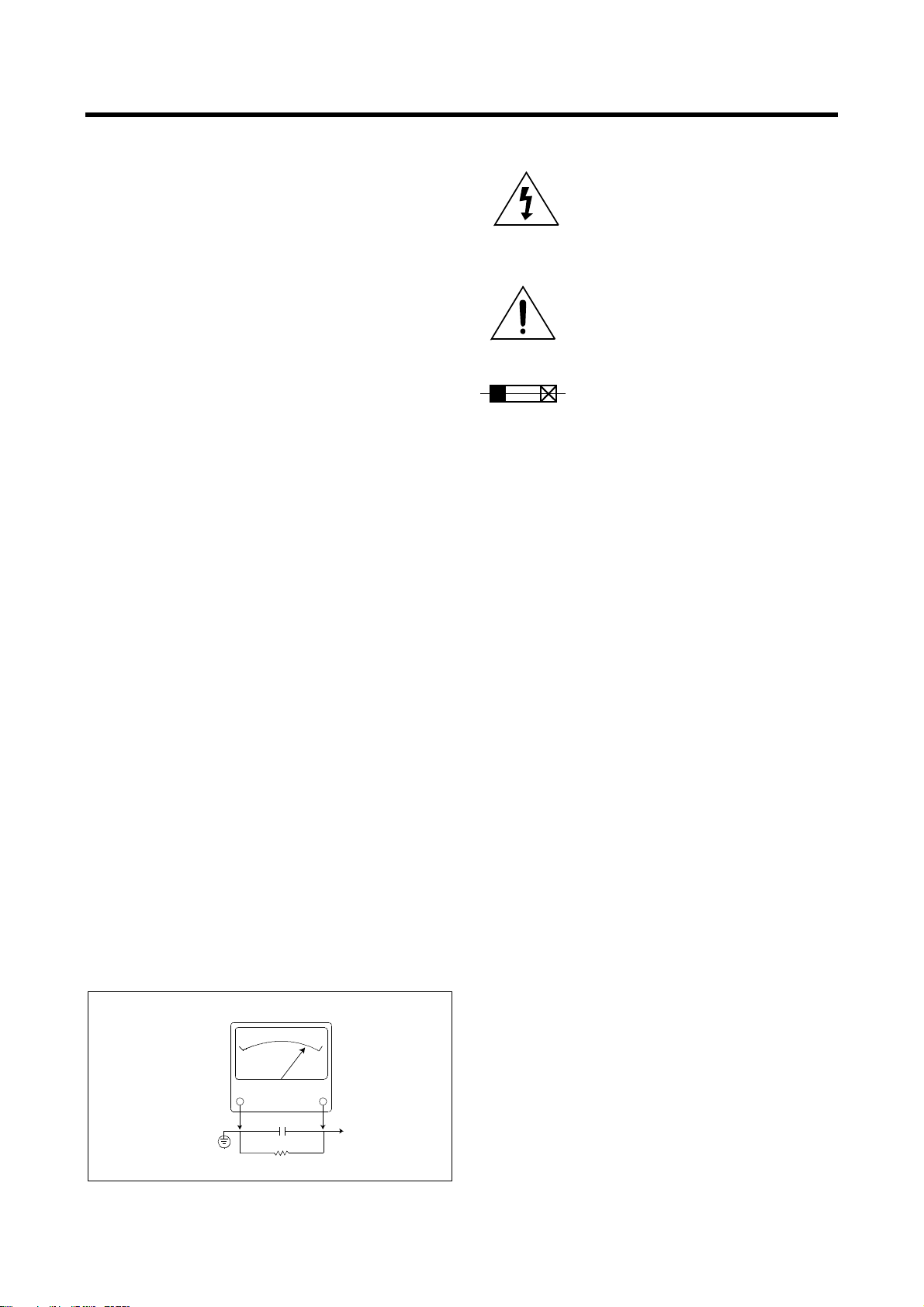
7. After re-assembly of the set always perform an A.C. leakage test
on all exposed metallic parts of the cabinet, (the channel selector
knob, antenna terminals, handle and screws) to be sure the set is
safe to operate without danger of electrical shock. Do not use a
line isolation transformer during this test. Use an A.C. voltmeter,
having 5000 ohms per volt or more sensitivity, in the following
manner : connect a 1500 ohm 10 watt resistor, paralleled by a 15
mfd. 150V A.C. type capacitor between a known good earth
ground (9water pipe, conduit, etc.) and the exposed metallic parts,
one at a time. Measure the A.C. voltage across the combination of
1500 ohm resistor and 0.15 MFD capacitor. Reverse the A.C. plug
and repeat A.C. voltage measurements for each exposed metallic
part. Voltage measured must not exceed 0.75 volts R.M.S. This
corresponds to 0.5 milliamp A.C. Any value exceeding this limit
constitutes a potential shock hazard and must be corrected immediately.
A.C. VOLTMETER
GRAPHIC SYMBOLS :
The lightning flash with arrowhead symbol,
within an equilateral triangle, is intended to alert
the service personnel to the presence of uninsulated “ dangerous voltage” that may be of sufficienty magnitude to constitute a risk of electric
shock.
The exclamation point within an equilateral triangle is intended to alert the service personnel
to the presence of important safety information
in service literature.
Fuse symbol is printed on pcb adjacent to the
fuse, with “ RISK OF FIRE REPLACE FUSE AS
MARKED” . The symbol is explained in the service manual with the following wording or equivalent.
CAUTION :
FOR CONTINUED PROTECTION AGAINST FIRE
HAZARD, REPLACE ONLY WITH SAME TYPE (6.3A, 125V)” and
“
ATTENTION
: AFIN D’ ASSU UNE PROTECTION PERMANENTE
CONTRE LES RISQUES D’ INCENDIE, REMPLACER UNIQUEMENT PAR UN FUSIBLE DE MEME TYPE ET DE ” 6.3A, 125V” .
SUBJECT : X-RADIATION
1. Be sure procedures and instructions to all service personnel cover
the subject of X-rays in current T.V. receivers is the picture tube.
However, this tube does not emit X-rays when the high voltage is
at the factory specified level. The proper value is given in the applicable schematic. Operation at higher voltages may cause a failure
of the picture tube or high voltage supply and, under certain circumstances, may produce radiation in excess of desirable levels.
2. Only factory specified C.R.T. anode connectors must be used.
Degaussing shields also serve as X-ray shield in color sets.
Always re-install them.
3. It is essential that the serviceman has available an accurate and
reliable high voltage meter. The calibration of the meter should be
checked perio - dically against a reference standard. Such as the
one available at your distributor.
4. When the high voltage circuitry is operating properly there is no
possibility of an X-radiation problem. Every time a color chassis is
serviced, the brightness should be run up and down while monitoring the high voltage with a meter to be certain that the high voltage
does not exceed the specified value and that it is regulating correctly. We suggest that you and your service organization review
test procedures so that voltage regulation is always checked as a
standard servicing procedure. And that the high voltage reading be
recorded on each customer’ s invoice.
5. When troubleshooting and making test measurements in a receiver
with a problem of excessive high voltage, avoid being unnecessarily
close to the picture tub eand the high voltage compartment.
Do not operate the chassis longer than is necessary to locate the
cause of excessive voltage.
6. Refer to HV, B+and Shutdown adjustment procedures described in
the appropriate schematic and diagrams(where used).
Good earth ground,
such as the water
pipe, conduit, etc.
0.15 uF
1500 OHM
10WATT
Place this probe
on each exposed
metal part.
2
Page 4

SUBJECT : IMPLOSION
1. All direct viewed picture tubes are equipped with an integral implosion protection system, but care should be taken to avoid damage
during installation. Avoid scratching the tube. If scratched, replace
it.
2. Use only recommended factory replacement tubes.
SUBJECT : TIPS ON PROPER INSTALLATION
1. Never install any receiver in closed-in recess, cubbyhole or closely
fitting shelf space over, or close to heat duct, or in the path of
heated air flow.
2. Avoid conditions of high humidity such as : Outdoor patio installations where dew is a factor. Near steam radiators where steam
leakage is a factor, etc.
3. Avoid placement where draperies may obstruct rear venting. The
customer should also avoid the use of decorative scarves or other
coverings which might obstruct ventilation.
4. Wall and shelf mounted installations using a commercial mounting
kit, must follow the factory approved mounting instructions. A
receiver mounted to a shelf or platform must retain its original
feet(or the equivalent thickness in spacers) to provide adequate
are flow across the bottom, bolts or screws used for fasteners
must not touch and parts or wiring. Perform leakage test on customized installations.
5. Caution customers against the mounting of a receiver on sloping
shelf or a tilted position, unless the receiver is properly secured.
6. A receiver on a roll-about cart should be stable on its mounting to
the cart. Caution the customer on the hazards of trying to roll a cart
with small casters across thresholds or deep pile carpets.
7. Caution customers against the use of a cart or stand which has not
been listed by underwriters laboratories, inc. For use with their
specific model of television receiver or generically approved for
use with T.V.’ s of the same or larger screen size.
3
Page 5

2. Specification
General
Power Requirement AC 120V, 60Hz
Power Consumption 250W (1.7W in standby)
Dimensions(W/H/D) 890 x 573 x 560 mm
Weight 64kg
Antenna Two 75 ohm external input terminals for UHF/VHF/Cable
One 75ohm external output terminal for Cable
RF Band Coverage VHF 2 ~ 13
UHF 14 ~ 69
CATV 1, 14 ~ 125
Picture
Screen Size 32 inches Pure Flat 16:9 Aspect ratio
Display Format 1920 x 1080i (Digital)
Upconversion to 1080i with line doubling (NTSC)
Horizontal Resolution 800 Lines
Sound
Digital Audio Dolby Digital AC-3 / Pro logic
NTSC Audio Multi-CH TV Stereo (MTS) / Second Audio Program (SAP)
Audio Power 8W / ch (Main L/R, Woofer), 5W / ch (Center, SL, SR)
Number of Inputs / Outputs
A/V In 4 each (Video / L / R)
S-Video In 2 each
HD Component Video In 2 each ( Y/ Pb / Pr, R / G / B )
HD Component Audio In 1 each ( L / R / SL / SR / Center / Woofer )
Digital Audio In 2 each ( Coaxial / Optical )
Digital Audio Out 2 each ( Coaxial / Optical )
External Speaker Out 1 each ( SL / SR / Woofer)
4
Page 6
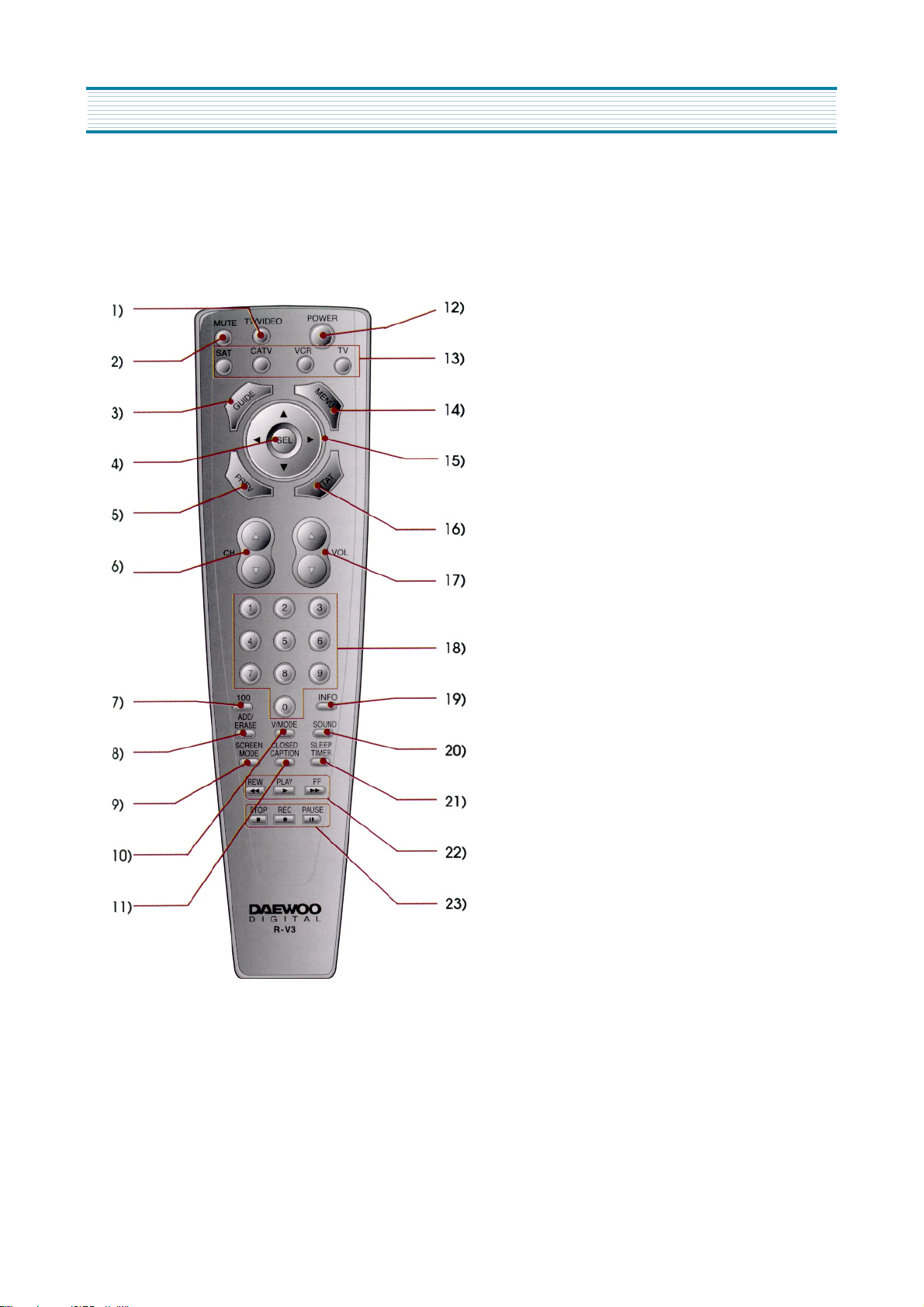
33. Remote control overview
The remote control has the following functions:
1. Power button
Press to turn the HDTV(and other equipment) on
and off.
2. MODE buttons
Press to select which equipment you wish your remote
control to operate:
* SAT(satelite)
* CATV (cable box)
* VCR
* TV
The Mode button you press will light up in red.
3. MENU button
Press once to display the HDTV menus. Press again to
make the menus disappear.
4. SEL ( Select) button
Press to select items on the HDTV menus.
5. Arrow buttons
Press to navigate through the HDTV menus.
6. STAT (Channel Station) button
Press to quickly select chammels to watch on your
HDTV.
7. VOL (Volume) buttons
press to raise and lower the volume on your HDTV.
8. Number buttons
Press to directly select channels or to enter the numbers
in the menus.
9. INFO (Information) button
Press to see the channel banner that provides information
while viewing your HDTV.
10. V MODE (Video Mode) button
Press to select a video mode : Normal, Dynamic,
Cinema or Customer.
5
Page 7

Remote control overview
11. SOUND button
Press to select a sound option : Mono, Stereo, or Secondary
Audio Programming (SAP). When you tune to a digital
channel, press to select various languages.
12. SLEEP TIMER button
Press to select the time before the HDRV turns off: 30
minutes, 60 minutes, 90 minutes, or 120 minutes.
13. CLOSED CAPTION button
Press to turn closed captions on and off.
14. FF (Fast Forward) button.
Press to fast forward a videocassette.
15. PLAY button
Press to play a videocassette.
16. PAUSE button
Press to pause a VCR.
24. PREV (Previous) button
Press to back up one menu at a time in the HDRV menus or to
return to the previous channel.
25. GUIDE button
Press this button to see the HDTV Program Guide.
26. MUTE button
Press to mute the HDTV sound.
27. TV / VIDEO button
Press to view components you have connected to the HDTV.
Press this button repeatedly to display:
* TV mode
* HD comp (HD Component Video)
* Video 1
* Video 2
* Video 3
* Video 4
17. REC(Record) button
Press to record a videotape.
18. STOP button
Press to stop a VCR.
19. REW (Rewind) button
Press to rewind a videocassette.
20. SCREEN MODE button
Press to select how to view your HDTV:
Normal or Full.
21. ADD / ERASE button
Press to add and erase channels on your HDTV.
22. 100 button
Press to select cable channels over 100 on TV or DSS
broadcasts.
23. CH (Chnnel) buttons
Press to select channels.
6
Page 8

4. Limited Warranty
Daewoo Electronics Corporation of America Inc. (also known as DECA) warrants this product to be free from defects in material
and workmanship and agrees to remedy any such defect.
This warranty covers 3 years labor and 3 years parts from the date of original purchase.
This warranty applies only to product purchased from authorized DECA dealer and used within the boundaries of U.S.A.
This warranty does not apply to product that has been improperly installed, subjected to usage for which the product was not
designed, misused or abused, damaged during transportation, or which has been altered in any way that affects the reliability or
detracts from its performance.
How you get warranty service
Warrany service can only be provided by an authorized DECA service center. For the closest authorized service center to you,
please contact your Dealer. In order to receive warranty service you must provide the authorized service center with a copy of proof
of purchase, signifying the date of purchase and the name of the Dealer from whom you purchased the product.
Statutory warranities
The purchase may have rights under existing provincial or federal laws, and where any terms of this warranty are prohibited by
such laws, they ard deemed null and void, but the remainder of the warranty shall remain in effect.
If you require further assistance, please call:
1-800-DAEWOO-8
7
Page 9
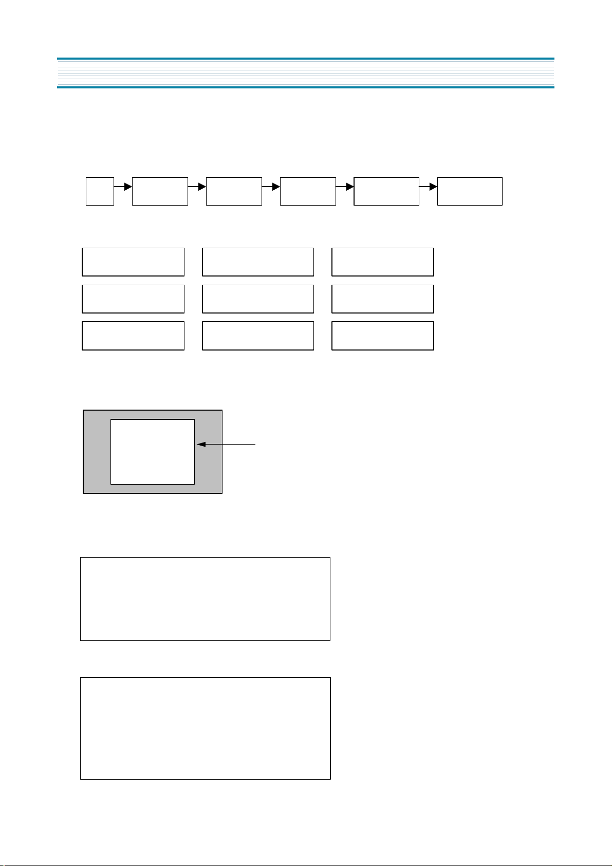
5. Service Modes
1. Entering to Service Mode
1) With the user remote control
Press the button in the following order.
1 MUTE SELECT POWER 1,2,3, …., 9MUTE
2) With the service remote control
S1 : Heat Run S2 : Screen Voltage S3 : Sound Controls
S4 : Video Controls S5 : Geometry S7 : White Balance
S8 : Sub Brightness S9 : Software Version S10: Factory Setting
2. Function of each service mode
1) S1 : Heat Run mode.
White Pattern
2) S2 : Screen Voltage Control mode
The vertical deflection is down, and a horizontal line appears on the screen.
3) S3 : Sound Controls mode
Equalizer : 60Hz, 250Hz, 1KHz, 3.5KHz, 10KHz
Ø
Main Volume : 0 → 63 → 31
Ø
Balance control : -31 → 31 → 0
Ø
Center Volume : 0 → 63 → 31
Ø
4) S4 : Video Controls mode
Ø Tint :0 → 63 → 31
Ø Brightness : 0 → 48 → 24
Ø Contrast : 0 → 48 → 24
Ø Color : 0 → 63 → 31
Ø Sharpness : 0 → 63 → 31
8
Page 10
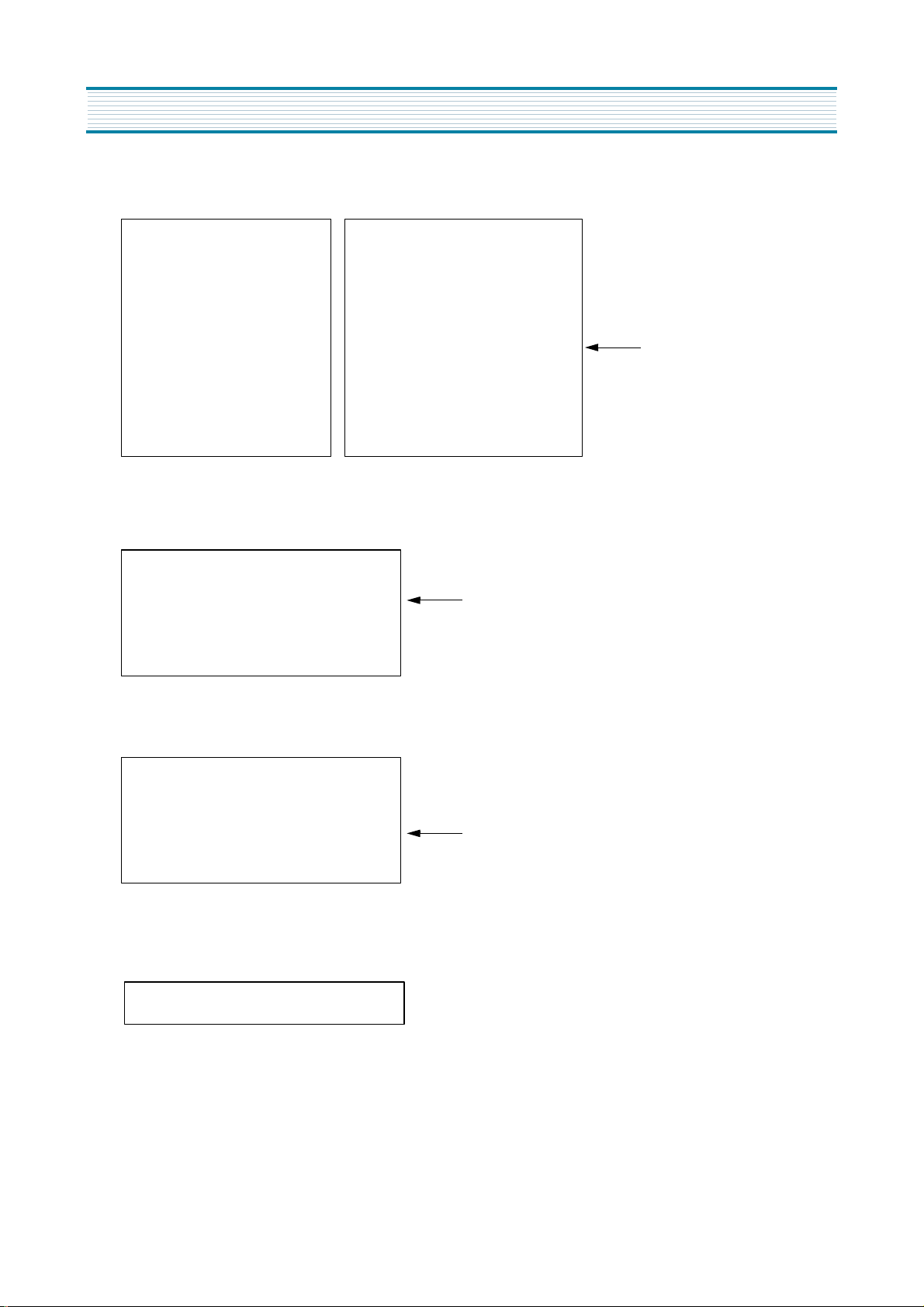
5) S5 : Geometry Adjustment mode
Service Modes
V Size Max
V Size
V Position
V C Linearity
Initial value
V S Linearity
H Size
H Position
Pincusion
31
0
26
23
31
53
70
32
Side Pin W
Side Pin S
Trapezoid
Side Pin Balance
H Duty
Parallelogram
H Focus Phase
H Focus Amplitude
22
34
33
31
31
28
31
60
6) S6 : No Use
7) S7 : White Balance Adjustment mode
White Balance Control
Drive R 128
Initial value
G 32
B 128
Bias R 64
G 224
B 64
8) S8 : Sub Brightness Adjustment mode.
Brightness 24
Contrast 22
Initial value
Color 32
Tint 37
Coring 63
VM Gain 27
VM Limit 40
9) S9 : Software Version
2000/04/06 08:30 AM
10) S12 : Factory Setting
9
Page 11

Service Modes
3. Selecting the adjusting items
1) With the user remote control
Pressing of ARROW s button changes the adjustment items. (t button for reverse order)
2) With the service remote control
Pressing of CHANNEL s button changes the adjustment items. (t button for reverse order)
4. Adjusting the data
1) With the user remote control
Pressing of ARROW button changes the value of data. ( button for reverse order)
2) With the service remote control
Pressing of VOLUME button changes the value of data. ( button for reverse order)
3
3
4
4
5. Exit from Service Mode
Press again to make service mode exit.
10
Page 12

6. General Adjustment
In the majority of cases, a high definition digital television will need basic adjustments such as high voltage, screen voltage, focus,
white balance, sub brightness, geometry, and blanking width. All adjustments should be performed after heat-running the set for at
least 20 minutes.
1. Press the S1 button on the service remote control, and then full white pattern will appear on the screen.
2. Press again the S1 button, and then the pattern will disappear.
High Voltage Adjustment
1. Operate the set for at least 20 minutes.
2. Connect the probe of high voltage meter to CRT ANODE.
3. Adjust the variable register RV801 on the power assembly so that high voltage may be to be between 29.5KV ~ 30.5KV.
Screen Voltage Adjustment
1. Press the S2 button on the service remote control.
1) Video Input mode will be VIDEO 1.
2) Vertical deflection will be down, and a horizontal line will appear on the screen.
2. Turn the variable screen volume of FBT to adjust screen voltage, at the point that a horizontal line only just appears.
Focus Adjustment
1. Tune on Retma pattern.
2. Turn the variable focus volume of FBT so that the center area of screen is sharp scanning line.
3. Turn the variable volume R522 on the CRT assembly so that the edge of screen may be sharp scanning line.
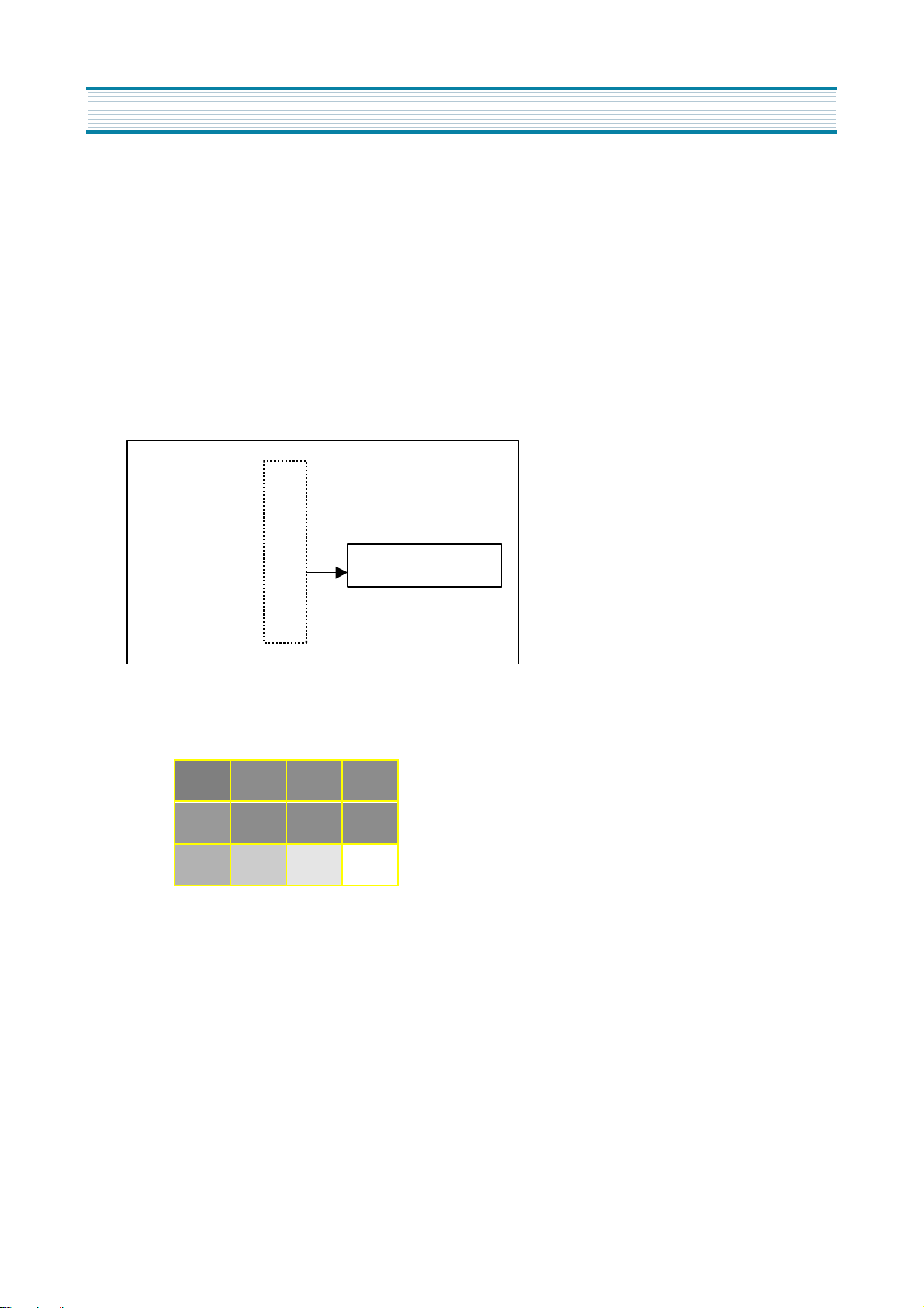
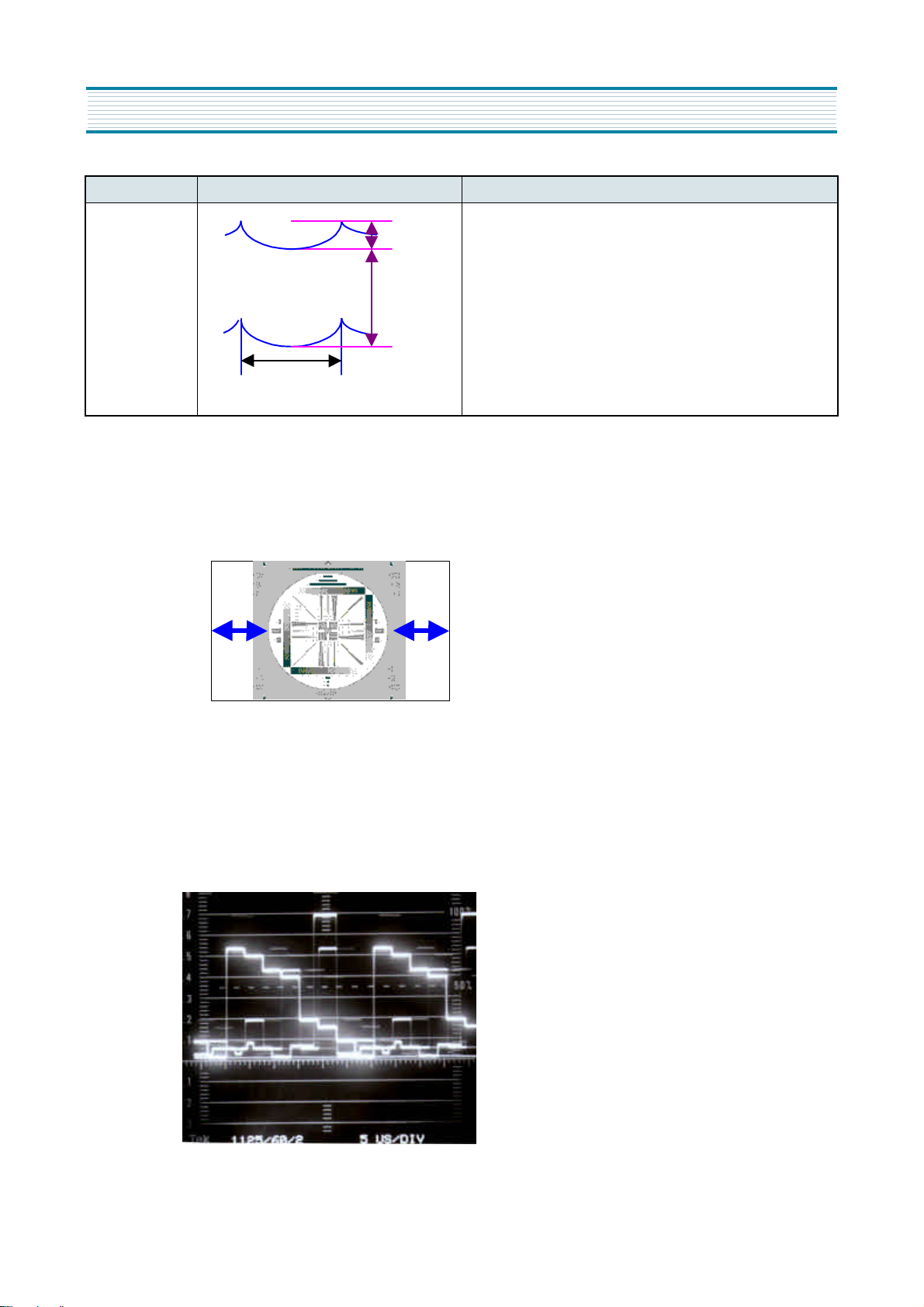
White Balance Adjustment
1. Input the Black & white signal to the HD Component jack on the rear panel.
<Black & White Pattern>
Light Area Check
Dark Area Check
2. The color temperature is the following.
3 x=0.270 6 0.005 y=0.270 6 0.005
3 Color temperature : 10500 8K
3. Light Area Adjustment
1) Press S7 button.
2) On the center of light area, attach the sensor of a white balance meter.
3) To be Y=125, turn the Light Beam control volume on the White & Black pattern generator.
4) To adjust the white balance of light area, select Drive R, G, B with CHANNEL Up or Down buttons, and adjust individual
vales with VOLUME Up or Down buttons.
11
Page 13
General Adjustment
4. Dark Area Adjustment
1) On the center of dark area, attach the sensor of a white balance meter.
2) To be Y=12, turn the Dark Beam control volume on the White & Black pattern generator.
3) To adjust the white balance of dark area, select Bias R, G, B with CHANNEL Up or Down buttons, and adjust individual
values with VOLUME Up or Down buttons.
4) Repeat two processes above until the white balance is completed.
Sub Brightness Adjustment
1. Tune on Retma Pattern.
2. Press S8 button.
3. The following OSD menu will appear on the screen, and the data are initial balues before adjusting.
Brightness 24
Contrast
Color
Tint
Coring
VM Gain
VM Limit
22
32
37
63
27
40
No need to adjust.
4. To be between Step 40% and 50% on the Contrast Chart, perform fine adjustment of sub brightness.
40% 30% 20% 10%
50% 0% 0% 5%
60% 70% 80% 100%
12
Page 14
Geometry
1. To adjust V-Position, H-Size, H-Position and so forth, tune on Retma Pattern.
2. To adjust Pincushion, Parallelogram and so forth, tune on Cross Hatch signal.
3. Screen Mode should be on Full mode, and the Video Mode should be on Normal mode.
4. Press S5 button to adjust Geometry.
5. With Up/Down buttons, perform the adjustment items in the following order.
Item Screen Image Adjustment Procedure
General Adjustment
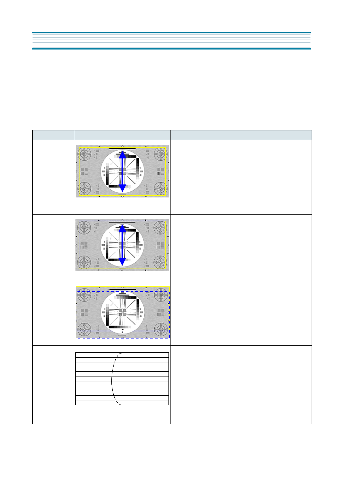
V Size Max.
1) Receive NTSC Retma signal.
2) The Screen mode should be selected on Full mode
3) Adjust Vertical Size so that over scanning rate may be 105%.
4) Check if the center circle is not only circular on Full mode
but also on Normal mode.
Over Scanning Rate: 105%
Vertical Size 1) There is no need to adjust.
2) Check if the value of data is "0".
Vertical
Position
1) Receive NTSC Retma signal.
2) The Screen mode should be selected on Full mode.
3) Adjost Vertical Position so that the circle of Retma signal
may be centered in the verical direction.
VC
Linearity
1) Receive NTSC Retma signal.
2) The Screen mode should be selected on Full mode.
3) When the center area of Retma signal's circle is S type in the
vertical direction, adjust VC Linearity so that vertical interval
may be the same.
13
Page 15
General Adjustment
Item Screen Image Adjustment Procedure
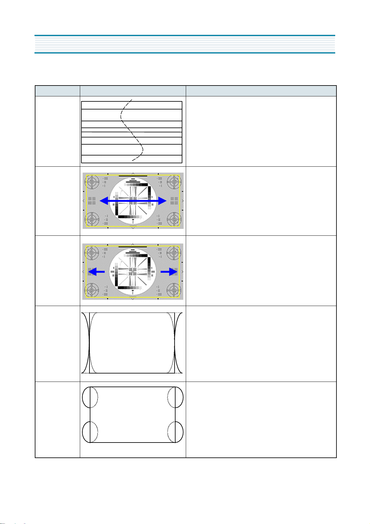
1) Receive NTSC Retma signal.
2) The Screen mode should be selected on Full mode
3) When the center area of Retma signal’s circle is S type
V S
Linearity
Horizontal
Size
in the vertical direction, adjust VS Linearity so that
vertical interval may be the same.
1) Receive NTSC Retma signal.
2) The Screen mode should be selected on Full mode
3) Adjust Horizontal Size for over scanning rate 106%
4) Check if the center circle of Retma signal is circle on
Normal mode.
Horizontal
Position
Pincushion
Side Pin W
1) Receive NTSC Retma signal.
2) The Screen mode should be selected on Full mode.
3) Adjust Vertical Position so that the circle of Retma
signal may be centered in the vertical direction.
1) Receive NTSC Cross Hatch signal.
2) The Screen mode should be selected on Full mode.
3) When the vertical lines of the left and right side are
distorted such as the left figure, adjust Pincushion so
that the vertical lines may be straight.
1) Receive NTSC Cross Hatch signal.
2) The Screen mode should be selected on Full mode.
3) When the vertical lines of the left and right side are
not straight but distorted in the W type, adjust Side
Pin W to correct the unbalanced vertical lines.
14
Page 16
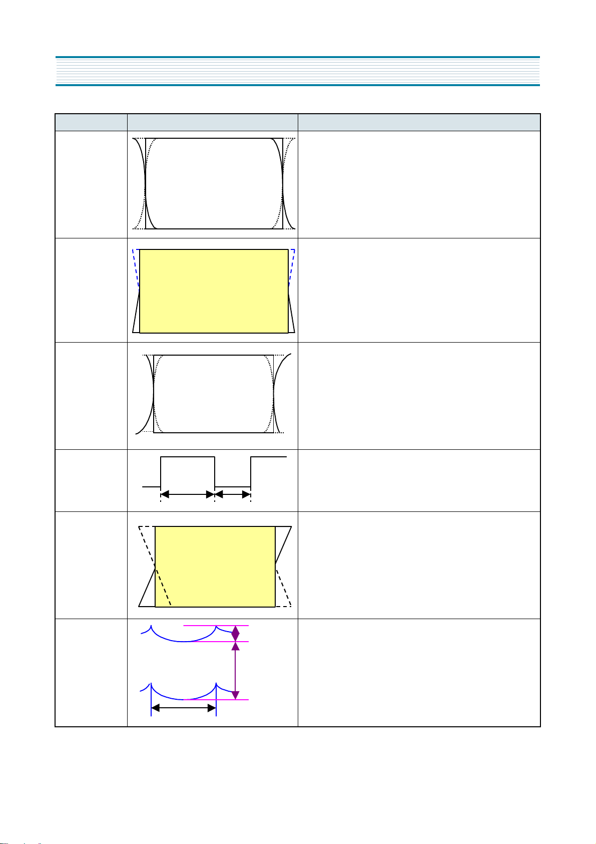
Item Screen Image Adjustment Procedure
1) Receive NTSC Cross Hatch signal.
2) The Screen mode should be selected on Full mode.
3) When the vertical lines of the left and right side is not
Side Pin S
straight but distorted in the S type, adjust Side Pin S
to correct the unbalanced vertical lines.
1) Receive NTSC Cross Hatch signal.
2) The Screen mode should be selected on Full mode.
3) When the screen shape is not rectangular but
Trapezoid
trapezoid, adjust Trapezoid to correct the unbalanced
shape.
1) Receive NTSC Cross signal.
2) The Screen mode should be selected on Full mode.
Side Pin
Balance
3) When both the left and right screen shape is not
symmetrical but on one side, adjust Side Pin Balance
to correct the unbalanced shape.
General Adjustment
H Duty
Paralle-
logram
H Focus
Phase
400Vp-p
900Vp-p
60HZ
1) There is no need to adjust.
2) Check if the value of data is "31".
1) Receive NTSC Cross Hatch signal.
2) The Screen mode should be selected on Full mode.
3) When both the left and right screen shape is on one
side, adjust Parallelogram to correct the unbalanced
shape.
1) There is no need to adjust, and check if the value of
data is "32".
2) Check that the focus on the right and left side is clear.
15
Page 17
General Adjustment
Item Screen Image Adjustment Procedure
H Focus
Amplitude
400Vp-p
900Vp-p
60Hz
1) There is no need to adjust, and check if the value of
data is "32".
2) Check if the focus on the right and left side is clear.
Blanking Width
1. Tune on NTS Retma pattern.
2. Press Screen mode on the remote control, and then slelct Normal. mode.
3. To be symmetrical the screen, adjust Blanking Width with rotating the variable volume RU19 on the Blanking Board.
Y Level Adjustment (to DTV Decoder module)
1. Tune on SMPTE Color Bar signal.
2. Connect a scope probe to pin 9 of PW06V.
3. Adjust RV900 such as the following figure so that the amplitude of Y level may be 0.7Vp-p.
16
Page 18

7. Special Adjustment (When replacing new circuit boards)
1. DTV Decoder module
1) Before replacing a new module, if seeing OSD menu is possible, record the adjusted data value of White Balance and
Geometry.
2) After replacing the defective module with a new one, memorize the value of data value to the new DTV decoder module
with the service remote control.
3) Perform the Y Level Adjustment.
2. Power assembly
1) After replacing a new assembly, perform High Voltage Adjustment.
2) The rest are no need to adjust.
3. Main assembly
1) After replacing a new assembly, perform Blanking Width Adjustment.
2) X-Rediation Protection Circuit Test
When service has been performed on the horizontal deflection system, high voltage system or B+ system, the X-Radiation
Protection Circuit Test must be tested for proper operation as follows:
2-1) Operate the HDTV set for at least 15 minutes.
2-2) Perform this test at the normal video and sound.
2-3) Check the cathode voltage of D837. Its voltage should be about 26VDC.
2-4) Connect a resister 24K(1/4W) with parallel to R925.
2-5) Then the set will be shut down, lighting up red to the power indicator.
2-6) If it is not, the circuit of X-Radiation Protection must be repaired before the set is returned to the customer.
3) The rest adjustment idems are no need to adjust.
4. Video assembly
1) No need to adjust.
17
Page 19
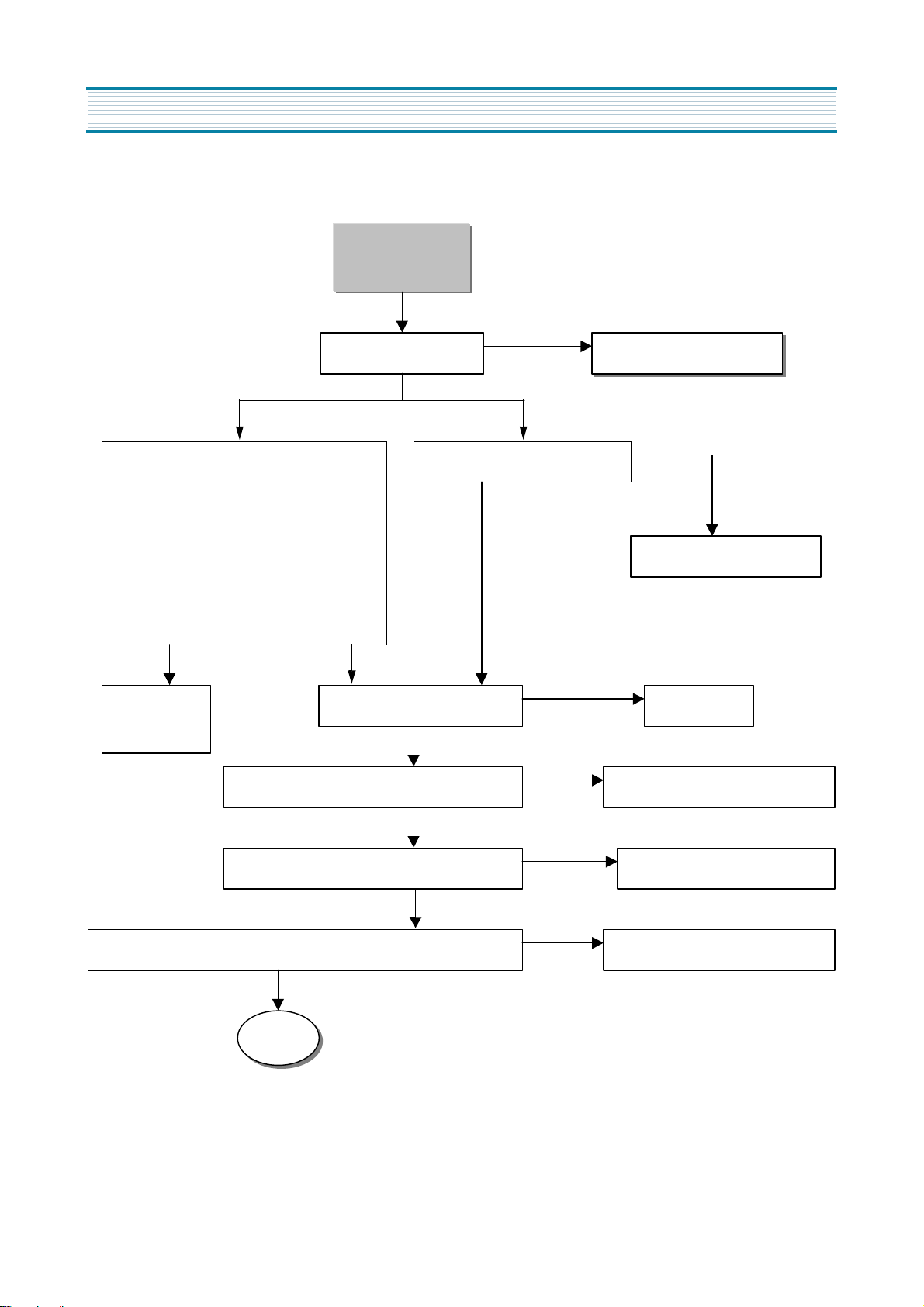
Special Adjustment
No Picture
(NTSC Signal)
OSD is on the screen.
AV Signal RF Signal
Check video signal of IC210.
Video 1 : CVBS to pins 43 ,Y to pin 45,
and C to pin 47
Video 2 : CVBS to pin 7
Video 3 : CVBS to pin 27
Video 4 : CVBS to pin 1 ,Y to pin 3, and
C to pin 5
NO
Check each
YES
CVBS is to pin 34 of IC210. Check IC210.
input signal.
Check if CVBS is 1Vp-p to pin 88 of ICA1. Check QCA9 , FA3, andQCA11
NO
To DTV Decoder Module
CVBS is to pin 13 of PW01M
NO
Check Tuner (U101).
YES
NO
YES
NO
YES
Check if Y output is 0.9Vp-p to Yout of PV1.
YES
Check if the color burst of C signal is 170~180mV to Cout of PV1.
V1
18
NO
Check QCA4, FA1, and QCA1
NO
Check QCA8, FA2, and QCA5
Page 20
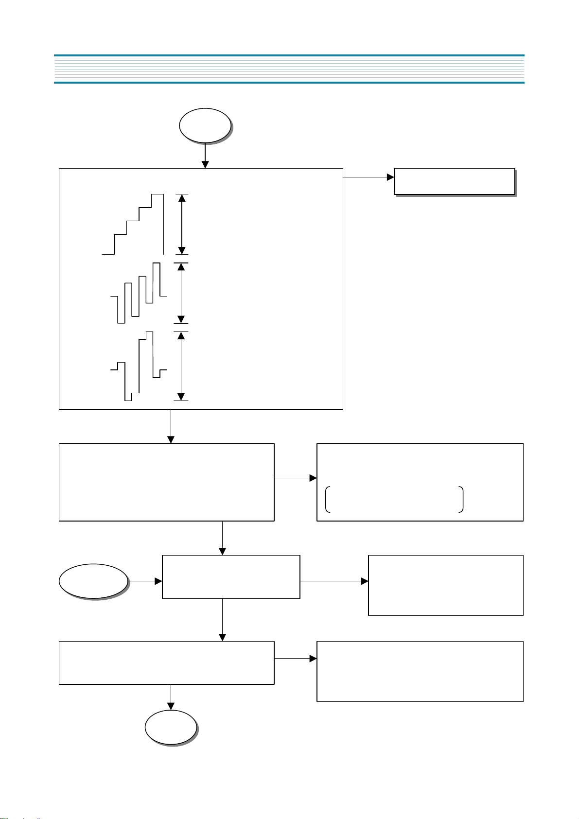
8. Troubleshooting charts.
V1
When input signal is color bar, check the following output level
to PA06D.
Y=0.7Vp-p ± 0.1Vp-p
Pb=0.6Vp-p ±0.1Vp-p
Pr=0.6Vp-p±0.1Vp-p
YES
NO
To DTV Decoder Module
Check the input and output signal of IC208.
Pins 9, 10, and 11 : Low (Base of QC215 : High)
Pin 14 : Y signal Pin 15 : Pb signal
Pin 4 : Pr signal
YES
Check if Y, Pb, and Pr are input
VIDEO
Check if Y, Pb, and Pr are input to pins 58, 59, and
57 of IC200.
to pins 45, 47, and 1 of IC200.
YES
V2
NO
NO
Check IC208
Check logical state to pin 52 of 212 IC.
NTSC, DTV signal : High
External HD Component : Low
Check the following parts.
NO
Y : Q204, Q205 Pb : Q202, Q203
Pr : Q200, Q201
Check the following parts.
Y : pin 27 of IC200, Q208, Q209, and Q210
Pb : pin 15 of IC200 Pr : pin 13 of IC200
19
Page 21
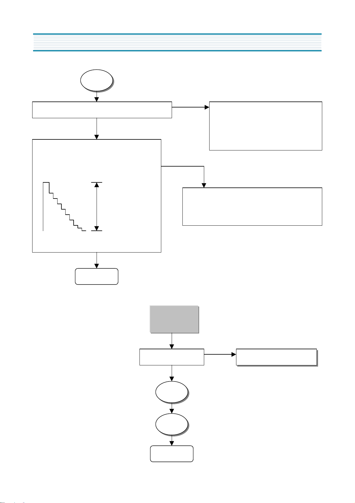
Troubleshooting charts
V2
Signals R, G, and B are to pins 2, 4, and 6 of PW07K.
YES
There are R signal to R504, G signal to R513, and
B signal.
<The signal amplitude of cathode G >
130Vp-p ±10Vp-p
Input signal : 10 steps pattern
Video mode : Normal mode
END
NO
Check the following parts.
R : pin 25 of IC201, Q218
G : pin31 of IC201, Q216
B : pin 28 of IC201, Q217
NO
Check the following parts.
R: pin8 of IC501, G: pin8 of IC502, B: pin 8 of IC503
Check 200V and 12V of PA17M.
No picture
(DTV Signal)
NO
OSD is on the screen. To DTV Decoder module
V1
V2
END
20
Page 22
Y, Pb, Pr Input
Pb/Pr.
Troubleshooting charts
OSD is on the screen. To DTV Decoder module
NO
YES
Check the SELECT SGINAL switch on the rear panel is to Y/
Select the switch to Y/Pb/Pr.
NO
If the switch is selected to R/G/B, the color of screen is pale green.
Check if Y/Pb/Pr signals are well
connected to input terminals.
YES
Check if pin 18 of IC212 is Low.
Check the input/output signal of IC207.
Pins 9, 10, and 11 : Low Pin 14 : Y signal
NO
Pin 15 : Pb signal Pin 4 : Pr signal Check IC207.
YES
Check the input/output signal of IC208.
NO
Pins 9, 10, and 11 : High (Base of QC215 : Low)
Check IC208
Pin 14 : Y signal Pin 15 : Pb signal Pin 4 : Pr signal
VIDEO
V2
END
21
Page 23

Troubleshooting charts
R, G, B Input
OSD is on the screen. To DTV Decoder module
NO
YES
NO
Check the SELECT SGINAL switch on the rear panel is to R/G/B. Select the switch to R/G/B.
YES
NO
Signals R, G, and B are to pins 7, 8, and 9 of IC201.
Check IC207.
YES
NO
Signals B-Y, Y and R-Y are to pins 3, 4, and 5 of IC201.
Check IC207.
YES
Check the input/output signal of IC207.
NO
Pins 9, 10, 11 : High
Check IC207.
Pin 13 : Y in
Pin 1 : B-Y in
Pin 3 : R-Y in
YES
Check the input/output signal of IC208.
Pins 9, 10, 11 : High (Base of QC215 : Low)
Pin 14 : Y signal Pin 15 : B-Y signal
Pin 4 : R-Y signal
VIDEO
V2
NO
Check IC208.
Check if pin 52 of IC212 is Low.
END
22
Page 24

No sound (NTSC)
R, L
Audio signal output is only R and L.
There are no sound to Center, SL, SR, and Woofer.
Troubleshooting charts
AV Signal
Check if the audio signals are input to the follow
pins of IC210 (CXA1855).
Video 1 : L to pin 44, R to pin 46
Video 2 : L to pin 8, R to pin 10
Video 3 : L to pin 25, R to pin 26
Video 4 : L to pin 2, R to pin 4
YES
Check if R, L signals are output to IC210.
Audio R : pin 32, Audio L : pin 33
Check if R, L signals are input and output to IC215.
Audio L input : pin 50, Audio L output : pin 37
RF Signal
Check the audio base-band signal to SIF of U101.
Amplitude of SIF : 800mVp-p ± 100mVp-p
YES
SIF is to pin 67 of IC215.
YES
NO
Check IC210
YES
NO
Check IC215
Audio R input : pin 51, Audio R output : pin 36
Decoder
Check if R, L signals are input to IC215
DEC_L : pin 56, DEC_R : pin 57
YES
Check if R, L signals are output to IC215.
Audio L : pin 28, Audio R : pin 27
YES
A1
YES
NO
To DTV Decoder module
Check IC215
NO
IC215 controls the volume of R, L.
The balance control is performed to DTV
decoder module.
23
Page 25

Troubleshooting charts
A1
Check if R, L signals are input and output to I609.
(The audio output of I609 is equalized signal.)
Audio L input : pin 1, Audio R input : pin 30
Audio L output : pin 12, Audio R output : pin 19
YES
Check if R, L signals are input and output to I607.
Audio L input : pin 4, Audio R input : pin 2
Audio L output : pin 8, Audio R output : pin 12
END
NO
Check I609
24
Page 26

No sound (External HD)
Check the input /output signal of volume control IC.
R, L
SL, SL, Center, and Woofer R, L
Troubleshooting charts
Check the following audio signals.
SL input / output : pins 12, 6 of I603
SR input / output : pins 16, 2 of I603
C input /output : pins 9, 7 of I602
W input /output : pins 9, 7 of I603
YES
A2
SL input / output : pins 6, 7 of I606
SR input / output : pins 4, 3 of I606
Center input / output : pins 6, 7 of I605
Woofer input / output : pins 4, 3 of I605
NO
Check I603
and I602.
Check if R, L signals are input and output to IC215.
HD_L input : pin 53 HD_L output : pin 37
HD_R input : pin 54, HD_R output : pin 36
NOYES
Decoder
A1
Check IC215.
END
Check the input /output signal of audio amplifier IC.
SL input / output : pins 4, 8 of I608
SR input / output : pins 1, 11 of I608
Center input / output : pins 1, 11 of I607
Woofer input / output : pins 2, 12 of I608
YES
END
25
Page 27

Troubleshooting charts
R, L
C, W, SR, SL
NO Sound
(RF DTV)
R, L Woofer, Center, SR, SL
Check DEC_R and DEC_L to PA05D. Check S_R, S_L, Center and Woofer to PA12D.
NO
To DTV Decoder module
Decoder
Check the following audio signals.
Decoder
A1
END
S_L input / output : pins 5, 6 of I603
S_R input / output : pins 1, 2 of I603
Center input /output : pins 8, 7 of I602
Woofer input /output : pins 8, 7 of I603
A2
END
26
Page 28

H/V Sync Check
(External HD Component Input)
R/G/B/Hs/Vs R/G/B with sync on green or Y/Pb/Pr
Troubleshooting charts
Check the input/output signal of IC202.
Pins 11, 10 : High (Base of QC215 : Low)
HS input : pin 13 HS output : pin 14
VS input : pin 1 VS output : pin 15
NO
YES
S2
Check IC202.
Check the input/output signal of IC203.
H_sync input : pin 6 H_sync output : pin 14
V_sync input : pin 8 V_sync output : pin 13
NO
Check the input/output signal of IC206.
Pins 9, 10, and 11 : High (To be HD Component )
Check IC203.
Low (No HD Component)
Check the input/output signal of IC203
G or Y input : pin 4
HS output : pin 14
VS output : pin 13
NO
Check IC202.
YES
YES
Check IC206.
NO
HD : from pin 15 of IC 206 to PW03M
VD : from pin 4 of IC 206 to PW03M
YES
Check the input signal of I402.
HD signal : pin 26 VD signal : pin 28
S1
27
Page 29

Troubleshooting charts
Check the following signals.
S1
HP : pin 6 of PW01V
5Vp-p
33.75KHz
VP : pin 7 of PW01V
5Vp-p
60Hz
YES
Check HP signal is to pin 13 of IC216 through IC204.
NO
Check IC204
NO
Check HP signal of Q426’s base.
NO
Check VP signal of Q415’s base.
YES
Check VP signal is to pin 21 of IC212.
NO
YES
Check IC204.
Check EVEN/ODD signal is to pin 46 of IC 212
YES NO
YES
Check HP signal is to pin 14 of IC216 .
Check EVEN/ODD signal is to pin 1 of IC216.
Pins 9, 10, and 11 : High (to be HD Component ), Low (no HD Component)
YES
Check IC209.
HP signal is input to pin 1. DEC_HS (HP) is output to pin 15.
EVEN/ODD (VP) signal is input to pin 13.
DEC_VS (EVEN/ODD) signal is output to pin 14.
Pins 9, 10, and 11 : High (to be HD Component ), Low (no HD Component)
YES
DEC_HS and DEC_VS of PA06D to DTV Decoder module
Check IC212.
NO
Check IC216.
Check IC209.
END
28
Page 30

H/V Sync Check
(RF DTV, RF NTSC, AV NTSC)
DEC_HS is to PA06D.
Troubleshooting charts
3.3Vp-p
NO
33.75KHz
DEC_VS is to PA06D.
3.3Vp-p
60Hz
YES
DEC_HS is input / output to pins 15, 2 of IC209.
DEC_VS is input / output to pins 14, 13 of IC209.
Pins 10, 11 of IC 202 : High (Base of QC215 : High)
YES
To DTV Decoder module
NO
Check IC 209.
DEC_HS is input to pin 12 of IC 202.
DEC_VS is input to pin 2 of IC 202.
H_sync is output to pin 14 of IC 202.
V_sync is output to pin 15 of IC 202.
Pins 10 and 11 of IC 202 : High (Base of QC215 : High)
S2
END
29
NO
Check IC 202.
Page 31

Troubleshooting charts
No Raster
Press POWER button, and wait for 2 minutes.
Power LED keeps continuously lighting up green.
YES
IC212 communicates with I402 on the IIC bus.
Check the pins 3 (SDA) and 4 (SCL) of I402.
5Vp-p
NO
YES
Check IC212
and I402.
Check pin 17 (H-Drive output) of I402.
NO
Check if TV micro- processor (IC212) communicates
with DTV Decoder module on UART.
If the LED changes from green to red, check pin 39
(TXD) of IC212.
5Vp-p
Check the pin 38 (RXD) of IC212 or pin 6 of PA05D.
3.3Vp-p
To DTV Decoder module
Vertical Deflection
Horizontal Deflection
Check H Drive signal to emitter of Q420.
12Vp-p
33.75KHz
0.7Vp-p
33.75KHz
High Voltage Drive
HD1
30
Page 32

HD1
Troubleshooting charts
Trigger pulse is input to pin 2 of I407.
2Vp-p
6Vp-p
33.75KHz
YES
The control voltage of H Drive is input to pin 5 of I407.
60Hz
0.5Vp-p
7Vp-p
NO
Check Q416, Q417
NO
Check pin 9 (E/W ) of IC402.
YES
H Drive signal is output to pin 3 of I407.
12Vp-p
33.75KHz
HD2
NO
Check I407.
31
Page 33

Troubleshooting charts
HD2
Check 200VA to PA14M. To No Power
NO
YES
H Drive signal is output to Source of Q423.
200Vp-p
33.75KHz
YES
Horizontal Drive B+ to R481 is about 130Vp-p ±10Vp-p .
60Hz
NO
Check Q423.
YES
The voltage waveform of Q425’s collector is the following.
1400Vp-p ±50Vp-p
END
10Vp-p
130Vp-p
If the impedance value of Q425’s
NO
collector is near zero Ω, the
horizontal deflection TR (Q425)
is dead. Replace Q425.
32
Page 34

High Voltage Drive
Check pin 17 (H-Drive output) of I402.
Troubleshooting charts
0.7Vp-p
33.75KHz
YES
Check H Drive signal to emitter of Q402.
12Vp-p
33.75KHz
NO
Trigger pulse is input to pin 2 of I401.
2Vp-p
NO
Check I402.
NO
Check Q403.
6Vp-p
33.75KHz
YES
The control voltage of high voltage feedback is input to
pin 5 of I401.
60Hz
0.25Vp-p
7Vp-p
33
NO
YES
Check I403 and high voltage
feedback circuits.
HVD1
Page 35

Troubleshooting charts
HVD1
High Voltage Drive signal is output to pin 3 of I401.
12Vp-p
33.75KHz
YES
NO
Check 200VB to PA14M. To No Power
YES
High Voltage Drive signal is output to Source of Q407.
200Vp-p
NO
Check I401.
NO
Check Q407.
33.75KHz
YES
FBT B+ to pin 15 of PW16P is about 130Vp-p ±10Vp-p.
60Hz
10Vp-p
110Vp-p
HVD2
NO
Check Q407.
34
Page 36

HVD2
Troubleshooting charts
Check EHT Drive signal to base of Q808.
NO
12Vp-p
33.75KHz
YES
The voltage waveform of Q810’s drain is the following.
815Vp-p
YES
Check emitter of Q401.
NO
Check Q810.
END
35
Page 37

Troubleshooting charts
Vertical Deflection
Vertical SAW waveform is to pin 8 of I402.
2.2Vp-p
60Hz
YES
The following waveform is to pin 1 of I412.
3.5Vp-p
0V
YES
NO
Check I402.
NO
Check vertical deflection circuits
around I412.
Vertical deflection waveform is to pin 5 of I412.
50Vp-p
60Hz
END
36
NO
Check vertical deflection circuits
around I412.
Page 38

No Power
(Standby Power : U801)
The Standby LED doesn’t light up red.
YES
Troubleshooting charts
Approximately 150VDC is to C806.
YES
The following waveform is to drain of U801.
320Vp-p
100KHz
YES
Check if voltages to PA17D is supplied to DTV
Decoder module and TV micro-processor.
NO
Check if F801 is open.
Check D801 (bridge rectifier).
Check the impedance value of between Source
NO
and Drain to U801. If the value is near zero Ω,
U801 is dead. Replace U801.
Check the parts caused a short-circuit to
NO
secondary circuits.
(3.3A, 3.3B, 5V, 32V, 12V, and –12V)
YES
When pressing Power button, the color of Power
LED is green
END
37
Page 39

Troubleshooting charts
No Power
Switch relay (Y802) doesn’t operate.
Fuse (F801) doesn’t short-circuits. Replace F801.
NO
YES
Bridge rectifier (D805) doesn’t short-circuits.
NO
Replace D805.
(The voltage of between Anode and Cathode to
D805 is 0.6V).
YES
NO
Both AC lines of power cord don’t short-circuit. Replace the parts caused a short-circuit.
YES
NO
PWR SW to PW15M is High. Check pin 26 of IC212.
NO
Q804 doesn’t defective. Replace Q804.
YES
Y802 (switch relay) Doesn’t defective.
YES
The parts doesn’t caused a short-circuit to
secondary circuits
YES
P1
NO
ReplaceY802.
NO
Replace defective parts with a new one.
38
Page 40

P1
Replace defective parts with
Troubleshooting charts
The following waveform is to pin 1 of U803 and U805.
370Vp-p
50~80KHz
END
NO Power
Switch relay operation (Y802) is OK.
NO
Check the primary circuits of SMPS IC,
and replace defective parts with a new one.
The parts doesn’t caused a shortcircuit to secondary circuits.
YES
Supply the power to PA17D. S/B SW to PW15 is High. Check pin 13 of IC212.
YES
NO
a new one.
NO
P2 P3
NO
39
Page 41

Troubleshooting charts
P2 P3
YES
Supply 200VA to PA14M. R803 is OK. ReplaceR803.
YES
Check Regulators.
(U807, U808, U809)
NONO
YES
R815 is OK.
YES
Q802, D815 are OK. Replace Q802, D815.
YES
Check U805.
NO
Replace R815.
NO
Supply 200VB to PA14M. R807 is OK. Replace R807.
YES
Q801, D810 are OK.
YES
Check U803.
END
YES
40
NONO
NO
Replace Q801, D810.
Page 42

DTV Channel Trouble
When NO Signal Searching is not display
Select Input Select on the Setup Menu, and Check
Check Signal Strength.
Check tuner power to pins 6, 11, and 15 of U101.
Troubleshooting charts
Check IF signal to pin 19 of U101. Check AGC to pin 3 of U101.
NO
NO
YES
Check TS stream signal to pins 122,
123, 124, 125 of IC100.
NO NO
Check B+, Clock and IIC Bus to
pins 94, 104, and 105 of IC100.
YES
Check Please Back-end A/V function.
END
YES
Change Tuner
U101.
Change IC100
41
Page 43

Troubleshooting charts
(Color and luminance signal is not output.)
Check Y, Pb, and Pr to pins 38, 33, and 39 of IC917(Video DAC).
No Picture to DTV RF
Check Pixcko to pin 27 of IC917.
YES
V1 V2
Mosaic Picture to DTV RF
Mosaic picture is displayed on the screen.
NO
Check 27MHz clock to pin 88 of IC901(Video decoder),
and Y/Pb/Pr to pin 93 ~ 125.
NO
If no signal, change IC901.
END
Check 97MHz clock to pin 68 of
IC902 and IC903.
Soldering condition to pins of IC901, IC902, and
IC903 might be wrong. Resolder the pins.
YES
No problem
END
42
NO
NO
Check Pixcko(27MHz) to pin 88
of IC901.
NO
If no signal, change IC901.
Page 44

Loss of H/V sync to DTV RF
L, R
Picture is scrolling due to horizontal or vertical sync loses.
Check H/V sync signal of Video decoder to PW06V.
Check 27MHz clock to pin 88 of IC901(Video decoder),
and Y/Pb/Pr to pin 93 ~ 125.
Troubleshooting charts
Check H/V sync. If no signal, change IC901.
NO
YES
To H/V Sync Check
(RF DTV, RF NTSC, AV NTSC)
END
No sound to DTV RF
(Audio L, R)
NO
Check audio L/R to pins 2, 4 of PW05V Check pins 21, 22 of IC920 (Codec IC).
YES
NO
Check pins 63, 64, 67, and 73 of IC912.
Decoder
YES
NO
END
Check pins 188, 190, and 197 of IC701 (Transport IC).
NO
If no signal, change IC701.
43
Page 45

Troubleshooting charts
C, W, SR, SL
C, W, SR, SL
No sound to DTV RF
(Audio Center, Woofer)
Check audio C/W to pins 2, 4 of PW12M. Check pins 23, 24 of IC920.
NO
YES
NO
Check pins 63, 64, 67, and 73 of IC912.
Decoder
YES
NO
Check pins 188, 190, and 197 of IC701 (Transport IC).
END
NO
If no signal, change IC701.
No sound to DTV RF
(Audio SL, SR)
Check audio C/W to pins 6, 8 of PW12M. Check pins 25, 26 of IC920.
NO
YES
NO
Check pins 63, 64, 67, and 73 of IC912.
Decoder
YES
NO
Check pins 188, 190, and 197 of IC701 (Transport IC).
END
NO
If no signal, change IC701.
44
Page 46

9. Part List (DSC-30W60N)
CAUTION
" ": The shaded areas in the schematic diagram and the parts list have especial characteristics important for safety and should be replaced only with types
!
identical to those in the original circuit or specified in the part list. Before replacing any of those components, read carefully the PRODUCT SAFETY NOTICE on
this manual. Do not degrade the safety of reciever through improper servicing.
WARNING :
BEFORE SERVICING THIS CHASSIS, READ THE “X-RAY RADIATION
PRECAUTION”,”SAFETY PRECAUTION” AND “PRODUCT SAFETY
NOTICE”ON THIS MANUAL.
LOC PART CODE PART NAME DESCRIPTION REMARKS
ZZ110 PEACPWD002 ACCESSORY AS DSC-3260N
30 49586110W1 MANUAL INSTRUCTION DSC-3260N
40 4958900001 MANUAL QUICK GUIDE DSC-3260N
ZZ120 PEBCSHD002 COVER BACK AS DSC-3260N
M211 4952100100 COVER BACK FR HIPS PAINT
M540 4855420200 SPEC PLATE PE FILM
M591 4951900100 DECO SPKR AS FR HIPS PAINT
M781 4857817630 CLOTH BLACK FELT 400X20X0.7
M782 4857817611 CLOTH BLACK FELT 200X20X0.7
ZZ130 PEPKCPD002 PACKING AS DSC-3260N
M641 6520010100 STAPLE PIN 18M/M J D O 1
M681 4851712701 BAND AS 3.3M
M801 4958000100 BOX CARTON DW-3
M811 4958100100 PAD EPS
M821 4858218700 BAG P.E FOAM+LDPE T0.5X1880X1380
ZZ131 48519A4410 CRT GROUND NET 3301H-1015-2P
ZZ132 58G0000114 COIL DEGAUSSING DC-3200
ZZ140 PECACAD002 CABINET AS DSC-3260N
M201A 4856015820 SCREW CRT FIX SWRM+SK5 L=35
M201B 4856215401 WASHER RUBBER CR T1.0
M201C 7128301212 SCREW TAPPING T2S WAS 3X12 MFZN BK
M201D 4857817610 CLOTH BLACK FELT 300X20X0.7
M201E 4857817610 CLOTH BLACK FELT 300X20X0.7
M211A 7122401612 SCREW TAPPTITE T2S TRS 4X16 MFZN BK
M211B 7122401612 SCREW TAPPTITE T2S TRS 4X16 MFZN BK
M211C 7122401612 SCREW TAPPTITE T2S TRS 4X16 MFZN BK
M211D 7122401612 SCREW TAPPTITE T2S TRS 4X16 MFZN BK
M211E 7122401612 SCREW TAPPTITE T2S TRS 4X16 MFZN BK
M230 4952300200 PANEL AV FRHIPS BK
M353 97P4602700 CLAMP CORD POLYETHYLENE BLK
M353A 7122401612 SCREW TAPPTITE T2S TRS 4X16 MFZN BK
M561 4955600100 MARK BRAND AL T1.0 DIA-CUTTING
M682 4856816300 CLAMP WIRE NYLON 6 (V0)
SP01A 7122401612 SCREW TAPPTITE T2S TRS 4X16 MFZN BK
SP02A 7122401612 SCREW TAPPTITE T2S TRS 4X16 MFZN BK
ZZ200 PEFMSJD002 MASK FRONT AS DSC-3260N
M201 4952000100 MASK FRONT FR HIPS PAINT
M251 4952500100 GRILL SPKR R PS SHEET T0.4
M252 4952500200 GRILL SPKR L PS SHEET T0.4
S601 4958300310 SPEAKER AS L 10W 8 OHM K128/101999B
S601A 7122401612 SCREW TAPPTITE T2S TRS 4X16 MFZN BK
LOC PART CODE PART NAME DESCRIPTION REMARKS
S602 4958300110 SPEAKER UNIT 5W 8OHM H114/101999B
S602A 7128301212 SCREW TAPPING T2S WAS 3X12 MFZN BK
S603 4958300210 SPEAKER AS R 10W 8 OHM K128/101999B
S603A 7122401612 SCREW TAPPTITE T2S TRS 4X16 MFZN BK
S604 1111111111 DSC-3260N 24.576MHZ
S604A 7122401412 SCREW TAPPING T2S TRS 4X14 MFZN BK
S605 1111111111 DSC-3260N 24.576MHZ
S605A 7122401412 SCREW TAPPING T2S TRS 4X14 MFZN BK
ZZ290 PEMPMSD002 PCB MAIN MANUAL AS DSC-3260N
C410 CEXF2E101V C ELECTRO 250V RSS 100MF 16X31.5
C419 CMXL2E105J C MYLAR 250V MEU 1MF J
C424 CMXL2E105J C MYLAR 250V MEU 1MF J
C433 CMXL2E105J C MYLAR 250V MEU 1MF J
C445 CEYF1H222C C ELECTRO RUS 50V 2200MF 18*35.5
C468 CMXM2A334J C MYLAR 100V 0.33MF J BULK
C476 CMYH3D332J C MYLAR 2KV BUP 3300PF J
C477 CMYH3D332J C MYLAR 2KV BUP 3300PF J
C479 CMYE2G364J C MYLAR 400V PU 0.36MF J
D408 DRU3AM---- DIODE RU3AM(HIGH SPEED)
D417 DFMLG12S-- DIODE FML-G12S
D420 DRU3AM---- DIODE RU3AM(HIGH SPEED)
D423 DFMRG5H--- DIODE DAMPER FMRG5H
D423A 4857027904 HEAT SINK AL EX (AN0DIZE)
D423B 7174301011 SCREW TAPPTITE TT2 RND 3X10 MFZN
D424 DRF1------ DIODE RF-1
D425 DRF1------ DIODE RF-1
D436 1NJM431L-- IC REGULATOR NJM431L
I401 1NE555---- IC TIMER PD NE555
I402 1UPC1884BC IC H/V OSC UPC1884BCT
I403 1KF353---- IC OPAMP KF353
I404 1KF353---- IC OPAMP KF353
I405 1LM358---- IC KA358
I407 1NE555---- IC TIMER PD NE555
I408 1MC7812--- IC REGULATOR MC7812 12V 1A (KA7812)
I409 1MC7812--- IC REGULATOR MC7812 12V 1A (KA7812)
I409A 4857031201 HEAT SINK AL 6063S
I409B 7174300811 SCREW TAPPTITE TT2 RND 3X8 MFZN
I410 1KA7809--- IC REGULATOR KA7809
I410A 4857027802 HEAT SINK AL EX
I410B 7174300811 SCREW TAPPTITE TT2 RND 3X8 MFZN
I411 1KF353---- IC OPAMP KF353
I412 1TDA8172-- IC V-OUT TDA8172
I412A 4857028207 HEAT SINK AL EX BK
I412B 7174300811 SCREW TAPPTITE TT2 RND 3X8 MFZN
!
!
!
!
!
!
45
Page 47

Part List (DSC-30W60N)
LOC PART CODE PART NAME DESCRIPTION REMARKS
I413 1KA7809--- IC REGULATOR KA7809
I414 1KA7805--- IC REGULATOR KA7805
!
!
I601 1CXA1315P- IC CONVERTER CXA1315
I602 1LA7220--- IC SWITCH LA7220
I603 1LA7220--- IC SWITCH LA7220
I605 1UPC1406HA IC UPC 1406HA
I606 1UPC1406HA IC UPC 1406HA
I607 1TA8256H-- IC AMP TA8256H
!
I607A 4857027534 HEAT SINK AL EXBK
I607B 7174300811 SCREW TAPPTITE TT2 RND 3X8 MFZN
I608 1TA8256H-- IC AMP TA8256H
!
I608A 4857027534 HEAT SINK AL EXBK
I608B 7174300811 SCREW TAPPTITE TT2 RND 3X8 MFZN
I609 1TDA7317-- IC AUDIO TDA7317
JP02 4959100250 JACK PIN BOARD DPAM-9913
JP03 4959100550 JACK PIN BOARD DPAE-9867
L401 58CD000002 COIL CHOKE TRANS DTL-04M
L403 58HD000001 COIL H-LINEARITY DCL-20U
L406 58CD000001 COIL CHOKE DCC-01M
M351 4953500100 HOLDER CORD FR HIPS BK
M351A 7122401412 SCREW TAPPING T2S TRS 4X14 MFZN BK
M381 4853812800 FRAME MAIN PCB FR HIPS BK
M381A 7128301212 SCREW TAPPING T2S WAS 3X12 MFZN BK
M381B 7128301212 SCREW TAPPING T2S WAS 3X12 MFZN BK
M721A 7122401412 SCREW TAPPING T2S TRS 4X14 MFZN BK
PA09S 4950711002 CONNECTOR SMH250-11+YT250+USW=600
PA12D 4950708003 CONNECTOR SMH250-08+YT250+USW=300
PA13D 4950706006 CONNECTOR SMH250-06+YT250+USW=300
PA15P 4950713002 CONNECTOR SMH250-13+YT250+ULW=550
PW01V 4859280820 CONN WAFER TAC-L13X-A1
PW02V 4859280820 CONN WAFER TAC-L13X-A1
PW03V 4859280820 CONN WAFER TAC-L13X-A1
PW04V 4859280820 CONN WAFER TAC-L13X-A1
PW14P 4859235620 CONN WAFER YW025-13
PW16P 4859235820 CONN WAFER YW025-15
P405 4959203120 CONN WAFER TBL-P05P-C1
Q407 T1RFS634-- FET IRFS634
!
!
Q407A 4957000700 HEAT SINK AL EX
Q407B 7174301011 SCREW TAPPTITE TT2 RND 3X10 MFZN
Q418 T1RFS830-- FET IRFS830
Q423 T1RFS830-- FET IRFS830
Q423A 4857027700 HEAT SINK AL EX BK
Q423B 7174301011 SCREW TAPPTITE TT2 RND 3X10 MFZN
Q425 T2SC5422-- TR 2SC5422
!
Q425A 4857027534 HEAT SINK AL EXBK
Q425B 7174301011 SCREW TAPPTITE TT2 RND 3X10 MFZN
Q425C 4857619500 INSU PLATE SILICON RUBBER T0.3
LOC PART CODE PART NAME DESCRIPTION REMARKS
R476 RW02Z478J- R WIRE WOUND 2W 0.47 J
R481 RX05V229J- R CEMENT 5W 2.2 OHM J VERTICAL
R506 RW02Z828J- R WIRE WOUND 2W 0.82 OHM
SW401 5S40403035 SW LEVER JRS-1301
T401 5DU0000024 TRANS PULSE DTP-01A
T402 58CD000002 COIL CHOKE TRANS DTL-04M
T403 5DD0000021 TRANS DRIVE DTD-01A
T404 5DU0000024 TRANS PULSE DTP-01A
T405 5DY0000023 TRANS DUMMY DTL-02M
U101 4959700350 TUNER TAUG-H005P
X401 4850L02310 RESONATOR CERA CSB503F30
ZZ200 PEMPJ2D002 PCB CHIP MOUNT B AS DSC-3260N
CC401 HCQK820JCA C CHIP CERA 50V CH 82PF J 2012
CC402 HCQK681JCA C CHIP CERA 50V CH 680PF J 2012
CC403 HCBK472KCA C CHIP CERA 50V X7R 4700PF K 2012
CC404 HCTAH109MB C CHIP TANTAL 25V 1MF M 3216
CC405 HCQK221JCA C CHIP CERA 50V CH 220PF J 2012
CC406 HCBK102KCA C CHIP CERA 50V X7R 1000PF K 2012
CC407 HCBH104KCA C CHIP CERA 25V X7R 0.1MF K 2012
CC408 HCBK682KCA C CHIP CERA 50V X7R 6800PF K 2012
CC409 HCQK391JCA C CHIP CERA 50V CH 390PF J 2012
CC410 HCQK390JCA C CHIP CERA 50V CH 39PF J 2012
CC411 HCQK221JCA C CHIP CERA 50V CH 220PF J 2012
CC412 HCQK821JCA C CHIP CERA 50V CH 820PF J 2012
CC413 HCBH104KCA C CHIP CERA 25V X7R 0.1MF K 2012
CC414 HCQK391JCA C CHIP CERA 50V CH 390PF J 2012
CC415 HCBK471KCA C CHIP CERA 50V X7R 470PF K 2012
CC416 HCQK101JCA C CHIP CERA 50V CH 100PF J 2012
CC419 HCBH104KCA C CHIP CERA 25V X7R 0.1MF K 2012
CC420 HCBH104KCA C CHIP CERA 25V X7R 0.1MF K 2012
CC421 HCBH104KCA C CHIP CERA 25V X7R 0.1MF K 2012
CC422 HCBH104KCA C CHIP CERA 25V X7R 0.1MF K 2012
CC423 HCBH104KCA C CHIP CERA 25V X7R 0.1MF K 2012
CC424 HCBH104KCA C CHIP CERA 25V X7R 0.1MF K 2012
CC425 HCBH104KCA C CHIP CERA 25V X7R 0.1MF K 2012
CC426 HCBH104KCA C CHIP CERA 25V X7R 0.1MF K 2012
CC427 HCTBF100MB C CHIP TANTAL 16V 10MF M 3528 TS
CC428 HCBH104KCA C CHIP CERA 25V X7R 0.1MF K 2012
CC606 HCTAJ478MB C CHIP TANTAL 35V 0.47MF M 3216 TS
CC607 HCBK102KCA C CHIP CERA 50V X7R 1000PF K 2012
CC608 HCBK102KCA C CHIP CERA 50V X7R 1000PF K 2012
CC609 HCTAH109MB C CHIP TANTAL 25V 1MF M 3216
CC610 HCBK102KCA C CHIP CERA 50V X7R 1000PF K 2012
CC611 HCBK102KCA C CHIP CERA 50V X7R 1000PF K 2012
CC612 HCBK102KCA C CHIP CERA 50V X7R 1000PF K 2012
CC613 HCBK102KCA C CHIP CERA 50V X7R 1000PF K 2012
CC614 HCBK102KCA C CHIP CERA 50V X7R 1000PF K 2012
46
Page 48

Part List (DSC-30W60N)
LOC PART CODE PART NAME DESCRIPTION REMARKS
CC615 HCBK102KCA C CHIP CERA 50V X7R 1000PF K 2012
CC617 HCTAH109MB C CHIP TANTAL 25V 1MF M 3216
CC618 HCTBH479MB C CHIP TANTAL 25V 4.7MF M 3528
CC619 HCTBH479MB C CHIP TANTAL 25V 4.7MF M 3528
CC620 HCTBH479MB C CHIP TANTAL 25V 4.7MF M 3528
CC621 HCTBH479MB C CHIP TANTAL 25V 4.7MF M 3528
CC622 HCTBH479MB C CHIP TANTAL 25V 4.7MF M 3528
CC623 HCTBH479MB C CHIP TANTAL 25V 4.7MF M 3528
CC624 HCTAH109MB C CHIP TANTAL 25V 1MF M 3216
CC625 HCTBH479MB C CHIP TANTAL 25V 4.7MF M 3528
CC626 HCBH103KCA C CHIP CERA 25V X7R 0.01MF K 2012
CC630 HCBH104KCA C CHIP CERA 25V X7R 0.1MF K 2012
CC631 HCBH104KCA C CHIP CERA 25V X7R 0.1MF K 2012
CC633 HCBH103KCA C CHIP CERA 25V X7R 0.01MF K 2012
CC635 HCTBH479MB C CHIP TANTAL 25V 4.7MF M 3528
CC636 HCTBH479MB C CHIP TANTAL 25V 4.7MF M 3528
CC637 HCTBH479MB C CHIP TANTAL 25V 4.7MF M 3528
CC638 HCTBH479MB C CHIP TANTAL 25V 4.7MF M 3528
CC639 HCTBH479MB C CHIP TANTAL 25V 4.7MF M 3528
CC643 HCBK473KCA C CHIP CERA 50V X7R 0.047MF K 2012
CC644 HCBH103KCA C CHIP CERA 25V X7R 0.01MF K 2012
CC645 HCBH103KCA C CHIP CERA 25V X7R 0.01MF K 2012
CC646 HCBH103KCA C CHIP CERA 25V X7R 0.01MF K 2012
CC647 HCBH103KCA C CHIP CERA 25V X7R 0.01MF K 2012
CC648 HCBH104KCA C CHIP CERA 25V X7R 0.1MF K 2012
CC649 HCBH224KCA C CHIP CERA 25V X7R 0.22MF K 2012
CC650 HCBK563KCA C CHIP CERA 50V X7R 0.056MF K 2012
CC651 HCBK473KCA C CHIP CERA 50V X7R 0.047MF K 2012
CC652 HCBK332KCA C CHIP CERA 50V X7R 3300PF K 2012
CC653 HCBK272KCA C CHIP CERA 50V X7R 2700PF K 2012
CC654 HCBK102KCA C CHIP CERA 50V X7R 1000PF K 2012
CC655 HCBK122KCA C CHIP CERA 50V X7R 1200PF K 2012
CC656 HCTAH109MB C CHIP TANTAL 25V 1MF M 3216
CC657 HCTAH109MB C CHIP TANTAL 25V 1MF M 3216
CC658 HCBH104KCA C CHIP CERA 25V X7R 0.1MF K 2012
CC659 HCBK122KCA C CHIP CERA 50V X7R 1200PF K 2012
CC660 HCBK102KCA C CHIP CERA 50V X7R 1000PF K 2012
CC661 HCBK272KCA C CHIP CERA 50V X7R 2700PF K 2012
CC662 HCBK332KCA C CHIP CERA 50V X7R 3300PF K 2012
CC663 HCBK563KCA C CHIP CERA 50V X7R 0.056MF K 2012
CC664 HCBH224KCA C CHIP CERA 25V X7R 0.22MF K 2012
CC665 HCBH104KCA C CHIP CERA 25V X7R 0.1MF K 2012
RC401 HRFT103JCA R CHIP 1/10 10K OHM J 2012
RC402 HRFT103JCA R CHIP 1/10 10K OHM J 2012
RC403 HRFT103JCA R CHIP 1/10 10K OHM J 2012
RC404 HRFT102JCA R CHIP 1/10 1K OHM J 2012
RC405 HRFT562JCA R CHIP 1/10 5.6K OHM J 2012
LOC PART CODE PART NAME DESCRIPTION REMARKS
RC406 HRFT682JCA R CHIP 1/10 6.8K OHM J 2012
RC407 HRFT103JCA R CHIP 1/10 10K OHM J 2012
RC408 HRFT513JCA R CHIP 1/10 51K OHM J 2012
RC409 HRFT684JCA R CHIP 1/10 680K OHM J 2012
RC410 HRFT103JCA R CHIP 1/10 10K OHM J 2012
RC411 HRFT223JCA R CHIP 1/10 22K OHM J 2012
RC413 HRFT153JCA R CHIP 1/10 15K OHM J 2012
RC415 HRFT562JCA R CHIP 1/10 5.6K OHM J 2012
RC416 HRFT223JCA R CHIP 1/10 22K OHM J 2012
RC417 HRFT364JCA R CHIP 1/10 360K OHM J 2012
RC418 HRFT102JCA R CHIP 1/10 1K OHM J 2012
RC419 HRFT103JCA R CHIP 1/10 10K OHM J 2012
RC420 HRFT472JCA R CHIP 1/10 4.7K OHM J 2012
RC421 HRFT472JCA R CHIP 1/10 4.7K OHM J 2012
RC422 HRFT152JCA R CHIP 1/10 1.5K OHM J 2012
RC423 HRFT332JCA R CHIP 1/10 3.3K OHM J 2012
RC424 HRFT332JCA R CHIP 1/10 3.3K OHM J 2012
RC425 HRFT183JCA R CHIP 1/10 18K OHM J 2012
RC426 HRFT103JCA R CHIP 1/10 10K OHM J 2012
RC427 HRFT393JCA R CHIP 1/10 39K OHM J 2012
RC434 HRFT103JCA R CHIP 1/10 10K OHM J 2012
RC436 HRFT512JCA R CHIP 1/10 5.1K OHM J 2012
RC438 HRFT513JCA R CHIP 1/10 51K OHM J 2012
RC439 HRFT332JCA R CHIP 1/10 3.3K OHM J 2012
RC440 HRFT222JCA R CHIP 1/10 2.2K OHM J 2012
RC441 HRFT103JCA R CHIP 1/10 10K OHM J 2012
RC442 HRFT562JCA R CHIP 1/10 5.6K OHM J 2012
RC443 HRFT102JCA R CHIP 1/10 1K OHM J 2012
RC444 HRFT103JCA R CHIP 1/10 10K OHM J 2012
RC445 HRFT102JCA R CHIP 1/10 1K OHM J 2012
RC447 HRFT103JCA R CHIP 1/10 10K OHM J 2012
RC448 HRFT912JCA R CHIP 1/10 9.1K OHM J 2012
RC449 HRFT103JCA R CHIP 1/10 10K OHM J 2012
RC450 HRFT273JCA R CHIP 1/10 27K OHM J 2012
RC451 HRFT102JCA R CHIP 1/10 1K OHM J 2012
RC452 HRFT102JCA R CHIP 1/10 1K OHM J 2012
RC453 HRFT822JCA R CHIP 1/10 8.2K OHM J 2012
RC454 HRFT103JCA R CHIP 1/10 10K OHM J 2012
RC456 HRFT183JCA R CHIP 1/10 18K OHM J 2012
RC457 HRFT472JCA R CHIP 1/10 4.7K OHM J 2012
RC459 HRFT103JCA R CHIP 1/10 10K OHM J 2012
RC462 HRFT102JCA R CHIP 1/10 1K OHM J 2012
RC463 HRFT681JCA R CHIP 1/10 680 OHM J 2012
RC464 HRFT102JCA R CHIP 1/10 1K OHM J 2012
RC465 HRFT102JCA R CHIP 1/10 1K OHM J 2012
RC467 HRFT103JCA R CHIP 1/10 10K OHM J 2012
RC468 HRFT102JCA R CHIP 1/10 1K OHM J 2012
47
Page 49

Part List (DSC-30W60N)
LOC PART CODE PART NAME DESCRIPTION REMARKS
RC469 HRFT102JCA R CHIP 1/10 1K OHM J 2012
RC470 HRFT103JCA R CHIP 1/10 10K OHM J 2012
RC471 HRFT471JCA R CHIP 1/10 470 OHM J 2012
RC472 HRFT562JCA R CHIP 1/10 5.6K OHM J 2012
RC473 HRFT103JCA R CHIP 1/10 10K OHM J 2012
RC474 HRFT682JCA R CHIP 1/10 6.8K OHM J 2012
RC475 HRFT513JCA R CHIP 1/10 51K OHM J 2012
RC476 HRFT122JCA R CHIP 1/10 1.2K OHM J 2012
RC477 HRFT101JCA R CHIP 1/10 100 OHM J 2012
RC602 HRFT101JCA R CHIP 1/10 100 OHM J 2012
RC612 HRFT224JCA R CHIP 1/10 220K OHM J 2012
RC613 HRFT224JCA R CHIP 1/10 220K OHM J 2012
RC614 HRFT224JCA R CHIP 1/10 220K OHM J 2012
RC615 HRFT224JCA R CHIP 1/10 220K OHM J 2012
RC616 HRFT224JCA R CHIP 1/10 220K OHM J 2012
RC617 HRFT224JCA R CHIP 1/10 220K OHM J 2012
RC618 HRFT101JCA R CHIP 1/10 100 OHM J 2012
RC619 HRFT302JCA R CHIP 1/10 3K OHM J 2012
RC620 HRFT101JCA R CHIP 1/10 100 OHM J 2012
RC621 HRFT471JCA R CHIP 1/10 470 OHM J 2012
RC623 HRFT472JCA R CHIP 1/10 4.7K OHM J 2012
RC624 HRFT101JCA R CHIP 1/10 100 OHM J 2012
RC626 HRFT162JCA R CHIP 1/10 1.6K OHM J 2012
RC627 HRFT182JCA R CHIP 1/10 1.8K OHM J 2012
RC631 HRFT472JCA R CHIP 1/10 4.7K OHM J 2012
RC633 HRFT101JCA R CHIP 1/10 100 OHM J 2012
RC634 HRFT622JCA R CHIP 1/10 6.2K OHM J 2012
RC635 HRFT512JCA R CHIP 1/10 5.1K OHM J 2012
RC636 HRFT622JCA R CHIP 1/10 6.2K OHM J 2012
RC637 HRFT622JCA R CHIP 1/10 6.2K OHM J 2012
RC638 HRFT682JCA R CHIP 1/10 6.8K OHM J 2012
RC639 HRFT392JCA R CHIP 1/10 3.9K OHM J 2012
RC640 HRFT682JCA R CHIP 1/10 6.8K OHM J 2012
RC641 HRFT333JCA R CHIP 1/10 33K OHM J 2012
RC642 HRFT393JCA R CHIP 1/10 39K OHM J 2012
RC643 HRFT303JCA R CHIP 1/10 30K OHM J 2012
RC644 HRFT333JCA R CHIP 1/10 33K OHM J 2012
RC646 HRFT622JCA R CHIP 1/10 6.2K OHM J 2012
RC647 HRFT512JCA R CHIP 1/10 5.1K OHM J 2012
RC648 HRFT622JCA R CHIP 1/10 6.2K OHM J 2012
RC649 HRFT223JCA R CHIP 1/10 22K OHM J 2012
RC650 HRFT223JCA R CHIP 1/10 22K OHM J 2012
RC651 HRFT472JCA R CHIP 1/10 4.7K OHM J 2012
RC654 HRFT102JCA R CHIP 1/10 1K OHM J 2012
RC655 HRFT333JCA R CHIP 1/10 33K OHM J 2012
RC656 HRFT393JCA R CHIP 1/10 39K OHM J 2012
RC657 HRFT393JCA R CHIP 1/10 39K OHM J 2012
LOC PART CODE PART NAME DESCRIPTION REMARKS
RC658 HRFT303JCA R CHIP 1/10 30K OHM J 2012
RC659 HRFT333JCA R CHIP 1/10 33K OHM J 2012
RC660 HRFT622JCA R CHIP 1/10 6.2K OHM J 2012
RJ01 HRFT000-CA R CHIP 1/10 0 OHM 2012
RJ03 HRFT000-CA R CHIP 1/10 0 OHM 2012
ZZ200 PEMPJ0D002 PCB MAIN (RHU) AS DSC-3260N
C418 CEXF1C471V C ELECTRO 16V RSS 470MF (10X12.5)TP
C420 CEXF1C471V C ELECTRO 16V RSS 470MF (10X12.5)TP
C422 CEXF1C471C C ELECTRO 16V RUS 470MF (10X12.5)TP
C440 CEXF1C471V C ELECTRO 16V RSS 470MF (10X12.5)TP
C442 CEXF1V102C C ELECTRO 35V RUS 1000MF (13X25) TP
C448 CEXF1H221C C ELECTRO 50V RUS 220MF (10X16) TP
C450 CEXF1H221C C ELECTRO 50V RUS 220MF (10X16) TP
C463 CCYB3D272K C CERA 2KV B 2700PF K
C465 CEXF2E330V C ELECTRO 250V RSS 33MF (13X25) TP
C466 CEXF2E220C C ELECTRO 250V RUS 22MF (13X20) TP
C474 CCXB3D151K C CERA 2KV B 150PF K (TAPPING)
C475 CCYB3D272K C CERA 2KV B 2700PF K
C488 CCYB3D272K C CERA 2KV B 2700PF K
C489 CEXF1C471C C ELECTRO 16V RUS 470MF (10X12.5)TP
C601 CEXF1V102C C ELECTRO 35V RUS 1000MF (13X25) TP
C602 CEXF1V102C C ELECTRO 35V RUS 1000MF (13X25) TP
C603 CEXF1V102C C ELECTRO 35V RUS 1000MF (13X25) TP
C621 CEXF1V102C C ELECTRO 35V RUS 1000MF (13X25) TP
C624 CEXF1V102C C ELECTRO 35V RUS 1000MF (13X25) TP
C626 CEXF1V102C C ELECTRO 35V RUS 1000MF (13X25) TP
C650 CEXF1C331C C ELECTRO RUS 16V 330MF (8.0*11.5)
R654 CEXF1C471C C ELECTRO 16V RUS 470MF (10X12.5)TP
ZZ200 PEMPJBD002 PCB MAIN M-10 AS DSC-3260N
E01 4856310600 EYE LET BSR T0.2 (R2.3)
E04 4856310600 EYE LET BSR T0.2 (R2.3)
E06 4856310600 EYE LET BSR T0.2 (R2.3)
E07 4856310600 EYE LET BSR T0.2 (R2.3)
E10 4856310600 EYE LET BSR T0.2 (R2.3)
E12 4856310600 EYE LET BSR T0.2 (R2.3)
E13 4856310600 EYE LET BSR T0.2 (R2.3)
E17 4856310600 EYE LET BSR T0.2 (R2.3)
E19 4856310600 EYE LET BSR T0.2 (R2.3)
E20 4856310600 EYE LET BSR T0.2 (R2.3)
E21 4856310600 EYE LET BSR T0.2 (R2.3)
E22 4856310600 EYE LET BSR T0.2 (R2.3)
E23 4856310600 EYE LET BSR T0.2 (R2.3)
E25 4856310600 EYE LET BSR T0.2 (R2.3)
E26 4856310600 EYE LET BSR T0.2 (R2.3)
E27 4856310300 EYE LET BSR T0.2 (R1.6)
E28 4856310300 EYE LET BSR T0.2 (R1.6)
E29 4856310300 EYE LET BSR T0.2 (R1.6)
48
Page 50

Part List (DSC-30W60N)
LOC PART CODE PART NAME DESCRIPTION REMARKS
E30 4856310300 EYE LET BSR T0.2 (R1.6)
E34 4856310600 EYE LET BSR T0.2 (R2.3)
E35 4856310300 EYE LET BSR T0.2 (R1.6)
E36 4856310300 EYE LET BSR T0.2 (R1.6)
E37 4856310300 EYE LET BSR T0.2 (R1.6)
E38 4856310300 EYE LET BSR T0.2 (R1.6)
E40 4856310300 EYE LET BSR T0.2 (R1.6)
E41 4856310300 EYE LET BSR T0.2 (R1.6)
E42 4856310300 EYE LET BSR T0.2 (R1.6)
E43 4856310300 EYE LET BSR T0.2 (R1.6)
E44 4856310600 EYE LET BSR T0.2 (R2.3)
E45 4856310600 EYE LET BSR T0.2 (R2.3)
E46 4856310600 EYE LET BSR T0.2 (R2.3)
E47 4856310300 EYE LET BSR T0.2 (R1.6)
E48 4856310300 EYE LET BSR T0.2 (R1.6)
E49 4856310300 EYE LET BSR T0.2 (R1.6)
E50 4856310300 EYE LET BSR T0.2 (R1.6)
E51 4856310300 EYE LET BSR T0.2 (R1.6)
E52 4856310300 EYE LET BSR T0.2 (R1.6)
E53 4856310300 EYE LET BSR T0.2 (R1.6)
E54 4856310300 EYE LET BSR T0.2 (R1.6)
E55 4856310300 EYE LET BSR T0.2 (R1.6)
E56 4856310300 EYE LET BSR T0.2 (R1.6)
PA18K 485923172S CONN WAFER YW025-04 (STICK)
PM601 485923162S CONN WAFER YW025-03 (STICK)
PM602 485923172S CONN WAFER YW025-04 (STICK)
PM603 485923162S CONN WAFER YW025-03 (STICK)
PW17K 485923192S CONN WAFER YW025-06 (STICK)
PW604 485923162S CONN WAFER YW025-03 (STICK)
R407 RS02Z229J- R M-OXIDE FILM 2W 2.2 OHM J(TAPPING)
R433 RS02Z109J- R M-OXIDE FILM 2W 1 OHM J (TAPPING)
R437 RS02Z109J- R M-OXIDE FILM 2W 1 OHM J (TAPPING)
R442 RS02Z271J- R M-OXIDE FILM 2W 270 OHM J (TAPPING)
R455 RS02Z121J- R M-OXIDE FILM 2W 120 OHM J (TAPPING)
R464 RS02Z104J- R M-OXIDE FILM 2W 100K OHM J TAPPING
R465 RS02Z271J- R M-OXIDE FILM 2W 270 OHM J (TAPPING)
R474 RS01Z471J- R M-OXIDE FILM 1W 470 OHM J (TAPPING)
R477 RS02Z271J- R M-OXIDE FILM 2W 270 OHM J (TAPPING)
R480 RS02Z229J- R M-OXIDE FILM 2W 2.2 OHM J(TAPPING)
R493 RS02Z271J- R M-OXIDE FILM 2W 270 OHM J (TAPPING)
R494 RS02Z390J- R M-OXIDE FILM 2W 39 OHM J (TAPPING)
R497 RS02Z180J- R M-OXIDE FILM 2W 18 OHM J (TAPPING)
R500 RS02Z129J- R M-OXIDE FILM 2W 1.2 OHM J (TAPPING)
ZZ200 PEMPJRD002 PCB MAIN RADIAL AS DSC-3260N
C401 CCXB1H391K C CERA 50V B 390PF K (TAPPING)
C402 CEXF1H100V C ELECTRO 50V RSS 10MF (5X11) TP
C403 CEXF1H479V C ELECTRO 50V RSS 4.7MF (5X11) TP
LOC PART CODE PART NAME DESCRIPTION REMARKS
C404 CEXF1C221V C ELECTRO 16V RSS 220MF (8X11.5) TP
C405 CMXM2A104J C MYLAR 100V 0.1MF J (TP)
C406 CMXM2A223J C MYLAR 100V 0.022MF J TP
C407 CCXB1H182K C CERA 50V B 1800PF K (TAPPING)
C408 CEXF1H109V C ELECTRO 50V RSS 1MF (5X11) TP
C409 CMXL1H105J C MYLAR 50V MEU 1MF J
C411 CMXM2A104J C MYLAR 100V 0.1MF J (TP)
C412 CEXF1V101V C ELECTRO 35V RSS 100MF (8X11.5) TP
C413 CEXF1E101V C ELECTRO 25V RSS 100MF (6.3X11) TP
C414 CEXF1V101V C ELECTRO 35V RSS 100MF (8X11.5) TP
C415 CEXF1E101V C ELECTRO 25V RSS 100MF (6.3X11) TP
C417 CMXM2A102J C MYLAR 100V 1000PF J (TP)
C423 CMXM2A104J C MYLAR 100V 0.1MF J (TP)
C425 CEXF1C101C C ELECTRO 16V RUS 100MF (6.3X11) TP
C426 CMXM2A104J C MYLAR 100V 0.1MF J (TP)
C427 CMXM2A683J C MYLAR 100V 0.068MF J (TP)
C428 CMXL1H105J C MYLAR 50V MEU 1MF J
C429 CMXM2A104J C MYLAR 100V 0.1MF J (TP)
C430 CEXF1H339V C ELECTRO 50V RSS 3.3MF (5X11) TP
C431 CMXM2A823J C MYLAR 100V 0.082MF J (TP)
C432 CEXF1H229V C ELECTRO 50V RSS 2.2MF (5X11) TP
C434 CEXF1C101C C ELECTRO 16V RUS 100MF (6.3X11) TP
C436 CEXF1H100V C ELECTRO 50V RSS 10MF (5X11) TP
C437 CEXF1H330C C ELECTRO 50V RUS 33MF (6.3X11) TP
C439 CMXM2A104J C MYLAR 100V 0.1MF J (TP)
C441 CMXM2A104J C MYLAR 100V 0.1MF J (TP)
C443 CEXF1H479V C ELECTRO 50V RSS 4.7MF (5X11) TP
C449 CMXB1H224J C MYLAR 50V EU 0.22MF J (TP)
C451 CEXF1H100V C ELECTRO 50V RSS 10MF (5X11) TP
C453 CEXF1H479V C ELECTRO 50V RSS 4.7MF (5X11) TP
C456 CEXF1H100V C ELECTRO 50V RSS 10MF (5X11) TP
C459 CCXB2H182K C CERA 500V B 1800PF K (TAPPING)
C460 CEXF1H470C C ELECTRO 50V RUS 47MF (6.3X11) TP
C461 CEXF1H479V C ELECTRO 50V RSS 4.7MF (5X11) TP
C462 CMXM2A182J C MYLAR 100V 1800PF J (TP)
C464 CMXM2A104J C MYLAR 100V 0.1MF J (TP)
C469 CEXF1H220V C ELECTRO 50V RSS 22MF (5X11) TP
C470 CEXF1C221V C ELECTRO 16V RSS 220MF (8X11.5) TP
C472 CEXF1C101C C ELECTRO 16V RUS 100MF (6.3X11) TP
C478 CCXB2H102K C CERA 500V B 1000PF K (TAPPING)
C481 CEXF2A479V C ELECTRO 100V RSS 4.7MF (5X11) TP
C482 CEXF2A100C C ELECTRO RUS 100V 10MF 5*11
C483 CMXB2A103J C MYLAR 100V EU 0.01MF J (TP)
C484 CEXF2A100C C ELECTRO RUS 100V 10MF 5*11
C485 CMXB2A103J C MYLAR 100V EU 0.01MF J (TP)
C486 CEXF2A479V C ELECTRO 100V RSS 4.7MF (5X11) TP
C487 CMXM2A473J C MYLAR 100V 0.047MF J (TP)
49
Page 51

Part List (DSC-30W60N)
LOC PART CODE PART NAME DESCRIPTION REMARKS
C490 CMXL2E104K C MYLAR 250V MEU 0.1MF K
C491 CMXL2E104K C MYLAR 250V MEU 0.1MF K
C492 CMXB2A103J C MYLAR 100V EU 0.01MF J (TP)
C604 CMXM2A104J C MYLAR 100V 0.1MF J (TP)
C605 CMXM2A104J C MYLAR 100V 0.1MF J (TP)
C606 CMXM2A104J C MYLAR 100V 0.1MF J (TP)
C620 CMXM2A104J C MYLAR 100V 0.1MF J (TP)
C622 CEXF1C470V C ELECTRO 16V RSS 47MF (5X11) TP
C623 CMXM2A104J C MYLAR 100V 0.1MF J (TP)
C625 CMXM2A104J C MYLAR 100V 0.1MF J (TP)
C635 CEXF1H100V C ELECTRO 50V RSS 10MF (5X11) TP
C637 CEXF1C470V C ELECTRO 16V RSS 47MF (5X11) TP
C638 CEXF1H479V C ELECTRO 50V RSS 4.7MF (5X11) TP
C639 CEXF1H479V C ELECTRO 50V RSS 4.7MF (5X11) TP
C640 CEXF1H479V C ELECTRO 50V RSS 4.7MF (5X11) TP
C641 CEXF1C470V C ELECTRO 16V RSS 47MF (5X11) TP
C643 CEXF1H100V C ELECTRO 50V RSS 10MF (5X11) TP
C646 CEXF1C470V C ELECTRO 16V RSS 47MF (5X11) TP
C647 CEXF1C101C C ELECTRO 16V RUS 100MF (6.3X11) TP
C649 CEXF1V101V C ELECTRO 35V RSS 100MF (8X11.5) TP
C650 CEXF1V101V C ELECTRO 35V RSS 100MF (8X11.5) TP
C653 CEXF1V101V C ELECTRO 35V RSS 100MF (8X11.5) TP
C686 CEXF1C101C C ELECTRO 16V RUS 100MF (6.3X11) TP
C687 CEXF1C101C C ELECTRO 16V RUS 100MF (6.3X11) TP
C688 CEXF1H100V C ELECTRO 50V RSS 10MF (5X11) TP
C692 CEXF1C101C C ELECTRO 16V RUS 100MF (6.3X11) TP
L405 5CPX101J-- COIL PEAKING PL 100UH J (TAPPING)
L608 5CPX100J-- COIL PEAKING PL 10UH J (TAPPING)
L609 5CPX101J-- COIL PEAKING PL 100UH J (TAPPING)
L610 5CPX101J-- COIL PEAKING PL 100UH J (TAPPING)
Q401 TKTC3198Y- TR KTC3198Y
Q402 TKTA1270Y- TR KTA1270Y (TP)
Q403 TKTC3198Y- TR KTC3198Y
Q404 TKTA1270Y- TR KTA1270Y (TP)
Q405 TKTC3202Y- TR KTC3202Y (TP)
Q406 TKTC3198Y- TR KTC3198Y
Q411 TKTC3198Y- TR KTC3198Y
Q413 TKTC3202Y- TR KTC3202Y (TP)
Q414 TKTA1270Y- TR KTA1270Y (TP)
Q415 TKTC3198Y- TR KTC3198Y
Q416 TKTC3198Y- TR KTC3198Y
Q417 TKTC3198Y- TR KTC3198Y
Q419 TKTA1270Y- TR KTA1270Y (TP)
Q420 TKTC3198Y- TR KTC3198Y
Q421 TKTC3202Y- TR KTC3202Y (TP)
Q422 TKTA1270Y- TR KTA1270Y (TP)
Q424 TKTC3198Y- TR KTC3198Y
LOC PART CODE PART NAME DESCRIPTION REMARKS
Q426 TKTC3198Y- TR KTC3198Y
Q427 TKTA1544-- TR KTA1544
Q428 TKTA1544-- TR KTA1544
Q429 TKTC3198Y- TR KTC3198Y
Q601 TKSR1004-- TR KSR-1004 (TAPPING)
Q602 TKTC3198Y- TR KTC3198Y
Q604 TKSR1004-- TR KSR-1004 (TAPPING)
Q605 TKTC3198Y- TR KTC3198Y
ZZ200 PEMPJAD002 PCB MAIN AXIAL AS DSC-3260N
A001 4959802224 PCB MAIN 330X246
C452 CCZB1H681K C CERA 50V B 680PF K
C645 CCZF1H103Z C CERA 50V F 0.01MF Z
D401 D1N4148--- DIODE 1N4148 (TAPPING)
D402 D1N4148--- DIODE 1N4148 (TAPPING)
D403 D1N4148--- DIODE 1N4148 (TAPPING)
D404 D1N4004--- DIODE 1N4004
D405 D1N4148--- DIODE 1N4148 (TAPPING)
D406 D1N4148--- DIODE 1N4148 (TAPPING)
D407 D1N4148--- DIODE 1N4148 (TAPPING)
D409 D1N4148--- DIODE 1N4148 (TAPPING)
D410 DUZ5R1BM-- DIODE ZENER UZ-5.1BM
D411 DUZ5R1BM-- DIODE ZENER UZ-5.1BM
D412 D1N4004--- DIODE 1N4004
D413 D1N4148--- DIODE 1N4148 (TAPPING)
D414 D1N4148--- DIODE 1N4148 (TAPPING)
D415 D1N4148--- DIODE 1N4148 (TAPPING)
D416 D1N4148--- DIODE 1N4148 (TAPPING)
D418 D1N4004--- DIODE 1N4004
D419 D1N4148--- DIODE 1N4148 (TAPPING)
D422 D1N4148--- DIODE 1N4148 (TAPPING)
D426 DUZ9R1BM-- DIODE ZENER UZ-9.1BM 9.1V
D427 DUZ8R2BM-- DIODE ZENER UZ-8.2B (8.2V)
D428 D1N4148--- DIODE 1N4148 (TAPPING)
D431 D1N4148--- DIODE 1N4148 (TAPPING)
D432 DUZ6R8BM-- DIODE ZENER UZ 6.8B 500MW SILICON
D433 D1N4148--- DIODE 1N4148 (TAPPING)
D434 DUZ12BM--- DIODE ZENER UZ-12BM (UNIZON)
D435 DUZ12BM--- DIODE ZENER UZ-12BM (UNIZON)
D437 DUZ12BM--- DIODE ZENER UZ-12BM (UNIZON)
D438 D1N4148--- DIODE 1N4148 (TAPPING)
D439 DUZ30BH--- DIODE ZENER UZ-30BH
D440 DUZ22BM--- DIODE ZENER UZ-22BM
D441 DUZ10BM--- DIODE ZENER UZ-10BM (TAPPING)
D442 D1N4148--- DIODE 1N4148 (TAPPING)
D443 D1N4148--- DIODE 1N4148 (TAPPING)
D601 D1N4148--- DIODE 1N4148 (TAPPING)
D602 D1N4148--- DIODE 1N4148 (TAPPING)
50
Page 52

Part List (DSC-30W60N)
LOC PART CODE PART NAME DESCRIPTION REMARKS
D603 DUZ10BM--- DIODE ZENER UZ-10BM (TAPPING)
D604 D1N4148--- DIODE 1N4148 (TAPPING)
D605 DUZ5R6BM-- DIODE ZENER UZ-5.6BM(TAPPING)
D606 DUZ5R6BM-- DIODE ZENER UZ-5.6BM(TAPPING)
D607 DUZ5R6BM-- DIODE ZENER UZ-5.6BM(TAPPING)
D608 DUZ5R6BM-- DIODE ZENER UZ-5.6BM(TAPPING)
D609 DUZ5R6BM-- DIODE ZENER UZ-5.6BM(TAPPING)
D610 DUZ5R6BM-- DIODE ZENER UZ-5.6BM(TAPPING)
D611 DUZ33B---- DIODE ZENER UZ-33B
D613 D1N4148--- DIODE 1N4148 (TAPPING)
D614 D1N4148--- DIODE 1N4148 (TAPPING)
J001-J050 85801065GY WIRE COPPER AWG22 1/0.65 TIN COATING
J053-J171 85801065GY WIRE COPPER AWG22 1/0.65 TIN COATING
L402 58C0000026 COIL BEAD HC-4035
L601 5CPZ100K02 COIL PEAKING 10UH K (AXIAL 3.5MM)
L607 5CPZ100K02 COIL PEAKING 10UH K (AXIAL 3.5MM)
R400 RD-2Z229J- R CARBON FILM 1/2 2.2 OHM J
R401 RD-AZ472J- R CARBON FILM 1/6 4.7K OHM J
R402 RD-AZ562J- R CARBON FILM 1/6 5.6K OHM J
R403 RD-AZ332J- R CARBON FILM 1/6 3.3K OHM J
R404 RD-2Z229J- R CARBON FILM 1/2 2.2 OHM J
R405 RD-AZ103J- R CARBON FILM 1/6 10K OHM J
R406 RD-2Z330J- R CARBON FILM 1/2 33 OHM J
R408 RD-AZ222J- R CARBON FILM 1/6 2.2K OHM J
R409 RD-AZ102J- R CARBON FILM 1/6 1K OHM J
R410 RD-AZ102J- R CARBON FILM 1/6 1K OHM J
R412 RD-AZ102J- R CARBON FILM 1/6 1K OHM J
R413 RD-AZ102J- R CARBON FILM 1/6 1K OHM J
R414 RD-AZ272J- R CARBON FILM 1/6 2.7K OHM J
R415 RD-4Z229J- R CARBON FILM 1/4 2.2 OHM J
R416 RD-2Z331J- R CARBON FILM 1/2 330 OHM J
R417 RD-AZ101J- R CARBON FILM 1/6 100 OHM J
R418 RD-AZ101J- R CARBON FILM 1/6 100 OHM J
R419 RD-4Z103J- R CARBON FILM 1/4 10K OHM J
R420 RD-AZ101J- R CARBON FILM 1/6 100 OHM J
R421 RD-AZ102J- R CARBON FILM 1/6 1K OHM J
R422 RD-AZ102J- R CARBON FILM 1/6 1K OHM J
R423 RD-AZ102J- R CARBON FILM 1/6 1K OHM J
R424 RD-AZ472J- R CARBON FILM 1/6 4.7K OHM J
R425 RD-AZ101J- R CARBON FILM 1/6 100 OHM J
R428 RD-4Z331J- R CARBON FILM 1/4 330 OHM J
R430 RD-AZ752J- R CARBON FILM 1/6 7.5K OHM J
R431 RD-AZ101J- R CARBON FILM 1/6 100 OHM J
R435 RD-4Z682J- R CARBON FILM 1/4 6.8K OHM J
R438 RD-AZ332J- R CARBON FILM 1/6 3.3K OHM J
R439 RD-AZ183J- R CARBON FILM 1/6 18K OHM J
R440 RD-AZ561J- R CARBON FILM 1/6 560 OHM J
LOC PART CODE PART NAME DESCRIPTION REMARKS
R441 RD-AZ102J- R CARBON FILM 1/6 1K OHM J
R443 RD-AZ561J- R CARBON FILM 1/6 560 OHM J
R445 RD-AZ473J- R CARBON FILM 1/6 47K OHM J
R446 RD-AZ272J- R CARBON FILM 1/6 2.7K OHM J
R450 RD-AZ103J- R CARBON FILM 1/6 10K OHM J
R452 RD-AZ132J- R CARBON FILM 1/6 1.3K OHM J
R453 RD-2Z229J- R CARBON FILM 1/2 2.2 OHM J
R454 RD-2Z182J- R CARBON FILM 1/2 1.8K OHM J
R456 RD-4Z220J- R CARBON FILM 1/4 22 OHM J
R458 RD-AZ102J- R CARBON FILM 1/6 1K OHM J
R459 RD-AZ153J- R CARBON FILM 1/6 15K OHM J
R461 RD-2Z102J- R CARBON FILM 1/2 1K OHM J
R462 RD-4Z102J- R CARBON FILM 1/4 1K OHM J
R463 RD-4Z103J- R CARBON FILM 1/4 10K OHM J
R469 RD-AZ102J- R CARBON FILM 1/6 1K OHM J
R470 RD-AZ333J- R CARBON FILM 1/6 33K OHM J
R472 RD-AZ473J- R CARBON FILM 1/6 47K OHM J
R473 RD-2Z100J- R CARBON FILM 1/2 10 OHM J
R475 RD-2Z470J- R CARBON FILM 1/2 47 OHM J
R478 RD-2Z103J- R CARBON FILM 1/2 10K OHM J
R479 RD-2Z330J- R CARBON FILM 1/2 33 OHM J
R486 RD-4Z229J- R CARBON FILM 1/4 2.2 OHM J
R487 RD-2Z272J- R CARBON FILM 1/2 2.7K OHM J
R488 RD-2Z272J- R CARBON FILM 1/2 2.7K OHM J
R492 RD-AZ202J- R CARBON FILM 1/6 2K OHM J
R495 RN-4Z4701F R METAL FILM 1/4 4.70K OHM F
R496 RN-4Z6202F R METAL FILM 1/4 62.0K OHM F
R499 RN-4Z3302F R METAL FILM 1/4 33K OHM F
R505 RN-4Z3302F R METAL FILM 1/4 33K OHM F
R507 RN-4Z6202F R METAL FILM 1/4 62.0K OHM F
R508 RN-4Z4701F R METAL FILM 1/4 4.70K OHM F
R520 RD-AZ100J- R CARBON FILM 1/6 10 OHM J
R601 RD-2Z331J- R CARBON FILM 1/2 330 OHM J
R602 RD-2Z331J- R CARBON FILM 1/2 330 OHM J
R603 RD-2Z331J- R CARBON FILM 1/2 330 OHM J
R604 RD-4Z229J- R CARBON FILM 1/4 2.2 OHM J
R605 RD-4Z229J- R CARBON FILM 1/4 2.2 OHM J
R606 RD-4Z229J- R CARBON FILM 1/4 2.2 OHM J
R607 RD-4Z229J- R CARBON FILM 1/4 2.2 OHM J
R608 RD-2Z331J- R CARBON FILM 1/2 330 OHM J
R609 RD-2Z331J- R CARBON FILM 1/2 330 OHM J
R610 RD-4Z229J- R CARBON FILM 1/4 2.2 OHM J
R611 RD-4Z229J- R CARBON FILM 1/4 2.2 OHM J
R612 RD-2Z331J- R CARBON FILM 1/2 330 OHM J
R613 RD-AZ473J- R CARBON FILM 1/6 47K OHM J
R623 RD-AZ182J- R CARBON FILM 1/6 1.8K OHM J
R626 RD-AZ273J- R CARBON FILM 1/6 27K OHM J
51
Page 53

Part List (DSC-30W60N)
LOC PART CODE PART NAME DESCRIPTION REMARKS
R629 RD-AZ471J- R CARBON FILM 1/6 470 OHM J
R630 RD-AZ302J- R CARBON FILM 1/6 3K OHM J
R632 RD-AZ302J- R CARBON FILM 1/6 3K OHM J
R633 RD-AZ101J- R CARBON FILM 1/6 100 OHM J
R637 RD-AZ101J- R CARBON FILM 1/6 100 OHM J
R639 RD-AZ101J- R CARBON FILM 1/6 100 OHM J
R641 RD-AZ101J- R CARBON FILM 1/6 100 OHM J
R642 RD-2Z153J- R CARBON FILM 1/2 15K OHM J
ZZ201 PETASWD002 PCB TERMINAL ANT AS DSC-3260N
JP01 4950M00310 MODULE RF BT11-0003
JP01A 4950703006 CONNECTOR YH025-03+YT250+ULW=250
JP01B 4950701004 CONNECTOR YT250+VLW=500
JP01C 1111111111 DSC-3260N 24.576MHZ
JP01D 1111111111 DSC-3260N 24.576MHZ
M301 4953000100 BRKT TUNER EGI T0.8
M301A 7128301212 SCREW TAPPING T2S WAS 3X12 MFZN BK
M361 4950800100 TERMINAL ANT AS FR HIPS BK
M361A 7122401612 SCREW TAPPTITE T2S TRS 4X16 MFZN BK
M361B 7128301212 SCREW TAPPING T2S WAS 3X12 MFZN BK 1
M751 4957500700 COVER SOCKET FR HIPS BK
M751A 7128301212 SCREW TAPPING T2S WAS 3X12 MFZN BK
ZZ202 PEBKMSD002 PCB BLANKING MANUAL DSC-3260N
IU1 1NE555---- IC TIMER PD NE555
PU1 4859231920 CONN WAFER YW025-06
ZZ200 PEBKJRD002 PCB BLANKING RADIAL DSC-3260N
CU1 CMXM1H102K C MYLAR 50V 1000PF K
CU2 CXCH1H820J C CERA 50V CH 82PF J (TAPPING)
CU3 CMXM1H102K C MYLAR 50V 1000PF K
CU4 CEXF1C101C C ELECTRO 16V RUS 100MF (6.3X11) TP
CU5 CCXB1H391K C CERA 50V B 390PF K (TAPPING)
CU6 CEXF1H100V C ELECTRO 50V RSS 10MF (5X11) TP
CU7 CXCH1H471J C CERA 50V CH 470PF J
QU1 TKTA1270Y- TR KTA1270Y (TP)
QU2 TKTA1270Y- TR KTA1270Y (TP)
QU3 TKTC3198Y- TR KTC3198Y
QU4 TKTC3198Y- TR KTC3198Y
RU18 RV5426503P R SEMI FIXED EVN-DJAA03B 50K OHM
ZZ200 PEBKJAD002 PCB BLANKING AXIAL DSC-3260N
A001 4959802824 PCB BLANK 330 X 246 X 1.6T
DU1 D1N4148--- DIODE 1N4148 (TAPPING)
DU2 D1N4148--- DIODE 1N4148 (TAPPING)
DU3 D1N4148--- DIODE 1N4148 (TAPPING)
JU1 85801065GY WIRE COPPER AWG22 1/0.65 TIN COATING
JU2 85801065GY WIRE COPPER AWG22 1/0.65 TIN COATING
JU3 85801065GY WIRE COPPER AWG22 1/0.65 TIN COATING
JU4 85801065GY WIRE COPPER AWG22 1/0.65 TIN COATING
RU1 RD-AZ472J- R CARBON FILM 1/6 4.7K OHM J
!
LOC PART CODE PART NAME DESCRIPTION REMARKS
RU10 RD-AZ103J- R CARBON FILM 1/6 10K OHM J
RU11 RD-AZ562J- R CARBON FILM 1/6 5.6K OHM J
RU12 RD-AZ103J- R CARBON FILM 1/6 10K OHM J
RU13 RD-AZ102J- R CARBON FILM 1/6 1K OHM J
RU14 RN-AZ2401F R METAL FILM 1/6 2.4K OHM F
RU15 RD-AZ472J- R CARBON FILM 1/6 4.7K OHM J
RU16 RD-AZ562J- R CARBON FILM 1/6 5.6K OHM J
RU2 RN-AZ2201F R METAL FILM 1/6 2.2K OHM F
RU3 RD-AZ183J- R CARBON FILM 1/6 18K OHM J
RU4 RD-AZ472J- R CARBON FILM 1/6 4.7K OHM J
RU5 RD-AZ102J- R CARBON FILM 1/6 1K OHM J
RU6 RD-AZ472J- R CARBON FILM 1/6 4.7K OHM J
RU7 RD-AZ103J- R CARBON FILM 1/6 10K OHM J
RU8 RD-AZ103J- R CARBON FILM 1/6 10K OHM J
RU9 RD-AZ102J- R CARBON FILM 1/6 1K OHM J
ZZ220 PEUNSWD002 PCB UNION AS DSC-3260N
C500 CEXF2E100V C ELECTRO 250V RSS 10MF (10X20) TP
C520 CCYE3D103P C CERA 2KV E 0.01MF P
C529 CEXF2C100V C ELECTRO 160V RSS 10MF (10X16) TP
C534 CEXF2C220V C ELECTRO 160V RSS 22MF (10X20) TP
C540 CMXF2G104J C MYLAR MPP 400V 0.1MF J
DY1 DH1L25RS-- LED (RED) HI-L25RS
DY2 DH1L25RS-- LED (RED) HI-L25RS
DY3 DH1L25RGD- "LED (R,G-3 COLOR)" HI-L25RGD
DY4 DH1L25RGD- "LED (R,G-3 COLOR)" HI-L25RGD
IY1 1SR9HP---- IC PREAMP SR-9HP
I501 1TDA6111Q- IC AMP VIDEO TDA6111Q
I501A 4857024613 HEAT SINK AL EX (NO ANODIZING)
I501B 7174300811 SCREW TAPPTITE TT2 RND 3X8 MFZN
I502 1TDA6111Q- IC AMP VIDEO TDA6111Q
I502A 4857024613 HEAT SINK AL EX (NO ANODIZING)
I502B 7174300811 SCREW TAPPTITE TT2 RND 3X8 MFZN
I503 1TDA6111Q- IC AMP VIDEO TDA6111Q
I503A 4857024613 HEAT SINK AL EX (NO ANODIZING)
I503B 7174300811 SCREW TAPPTITE TT2 RND 3X8 MFZN
JZ2 4859105340 JACK S-VHS YKF51-5359
JZ3 4859105450 JACK PIN BOARD YSC03P-4120-9S
M231 4952300100 PANEL CTRL FR HIPS PAINT
M491 4954900100 BUTTON CH ABS BK
M491A 7128301212 SCREW TAPPING T2S WAS 3X12 MFZN BK
M501 4955000100 DECO CTRL FR HIPS PAINT
M551 4955500100 DECO SENSOR PMMA MILKY
M551A 7128301212 SCREW TAPPING T2S WAS 3X12 MFZN BK
M552 4957900400 TUBE GSHS-1625 T0.3
PA07V 4950706009 CONNECTOR SMH250-06+YT250+USW=350
PA08V 4950703007 CONNECTOR SMH250-03+YT250+ULW=500
PA10V 4950704007 CONNECTOR SMH250-04+YT250+ULW=800
52
Page 54

Part List (DSC-30W60N)
LOC PART CODE PART NAME DESCRIPTION REMARKS
PA11V 4950706008 CONNECTOR SMH250-06+YT250+ULW=450
PA17M 4950706007 CONNECTOR SMH250-06+YT250+ULW=500
PA18M 4950704006 CONNECTOR SMH250-04+YT250+ULW=500
PA19C 4959203220 CONN WAFER LWL0640P-C1
PM1 4859238620 CONN WAFER YPW500-02
P2 4859236820 CONN WAFER YAW025-11
Q505 T2SA1837-- TR 2SA1837
Q505A 4857027802 HEAT SINK AL EX
Q505B 7174300811 SCREW TAPPTITE TT2 RND 3X8 MFZN
Q506 T2SC4793-- TR 2SC4793
Q506A 4857027802 HEAT SINK AL EX
Q506B 7174300811 SCREW TAPPTITE TT2 RND 3X8 MFZN
R507 RS03Y104J- R M-OXIDE FILM 3W 100K OHM J
R510 RS03Y104J- R M-OXIDE FILM 3W 100K OHM J
R517 RS03Y104J- R M-OXIDE FILM 3W 100K OHM J
R522 1111111111 DSC-3260N 24.576MHZ
R549 RS02Z221J- R M-OXIDE FILM 2W 220 OHM J
SG500 4SG0D00103 SPARK GAP S-23 900V-1.5KV
SG501 4SG0D00103 SPARK GAP S-23 900V-1.5KV
SG502 4SG0D00103 SPARK GAP S-23 900V-1.5KV
SG503 4SG0D00103 SPARK GAP S-23 900V-1.5KV
S500 4959303010 SOCKET CRT ISH-25S
ZZ200 PEUNJRD002 PCB UNION RADIAL AS DSC-3260N
CY1 CEXF1H100C C ELECTRO 50V RUS 10MF (5X11) TP
CY2 CBXF1H104Z C CERA SEMI 50V F 0.1MF Z (TAPPING)
CY3 CCXF1H102Z C CERA 50V F 1000PF Z (TAPPING)
CY4 CCXF1H102Z C CERA 50V F 1000PF Z (TAPPING)
C501 CCXF1H103Z C CERA 50V F 0.01MF Z (TAPPING)
C502 CEXF1H109V C ELECTRO 50V RSS 1MF (5X11) TP
C503 CEXF1C470V C ELECTRO 16V RSS 47MF (5X11) TP
C504 CMXM2A223J C MYLAR 100V 0.022MF J TP
C505 CMXL2E104K C MYLAR 250V MEU 0.1MF K
C506 CCXB2H561K C CERA 500V B 560PF K (TAPPING)
C507 CEXF1H109V C ELECTRO 50V RSS 1MF (5X11) TP
C508 CCXF1H103Z C CERA 50V F 0.01MF Z (TAPPING)
C509 CEXF1C470V C ELECTRO 16V RSS 47MF (5X11) TP
C510 CMXM2A223J C MYLAR 100V 0.022MF J TP
C511 CMXL2E104K C MYLAR 250V MEU 0.1MF K
C512 CCXB2H561K C CERA 500V B 560PF K (TAPPING)
C513 CEXF1H109V C ELECTRO 50V RSS 1MF (5X11) TP
C514 CCXF1H103Z C CERA 50V F 0.01MF Z (TAPPING)
C515 CEXF1C470V C ELECTRO 16V RSS 47MF (5X11) TP
C516 CMXM2A223J C MYLAR 100V 0.022MF J TP
C517 CXCH1H100D C CERA 50V CH 10PF D (TAPPING)
C518 CMXL2E104K C MYLAR 250V MEU 0.1MF K
C519 CCXB2H561K C CERA 500V B 560PF K (TAPPING)
C521 CXCH1H121J C CERA 50V CH 120PF J (TAPPING)
!
LOC PART CODE PART NAME DESCRIPTION REMARKS
C522 CCXF1H103Z C CERA 50V F 0.01MF Z (TAPPING)
C523 CEXF1H470V C ELECTRO 50V RSS 47MF (6.3X11) TP
C524 CCXF1H103Z C CERA 50V F 0.01MF Z (TAPPING)
C526 CCXB1H221K C CERA 50V B 220PF K (TAPPING)
C527 CCXF1H472Z C CERA 50V F 4700PF Z (TAPPING)
C528 CCXF1H472Z C CERA 50V F 4700PF Z (TAPPING)
C530 CCXF1H103Z C CERA 50V F 0.01MF Z (TAPPING)
C531 CCXF1H103Z C CERA 50V F 0.01MF Z (TAPPING)
C532 CEXF1C101C C ELECTRO 16V RUS 100MF (6.3X11) TP
C533 CEXF1C101C C ELECTRO 16V RUS 100MF (6.3X11) TP
C535 CXSL2H220J C CERA 500V SL 22PF J(TAPPING)
C536 CXCH1H100D C CERA 50V CH 10PF D (TAPPING)
C537 CXCH1H100D C CERA 50V CH 10PF D (TAPPING)
L500 5CPX829K-- COIL PEAKING 8.2UH K (RADIAL)
L501 5CPX829K-- COIL PEAKING 8.2UH K (RADIAL)
L502 5CPX829K-- COIL PEAKING 8.2UH K (RADIAL)
QY1 TKTC3198Y- TR KTC3198Y
QY2 TKTA1266Y- TR KTA1266Y (TP)
QY3 TKTA1266Y- TR KTA1266Y (TP)
Q500 TKTC3198Y- TR KTC3198Y
Q501 TKTC3198Y- TR KTC3198Y
Q502 TKTC3198Y- TR KTC3198Y
Q503 TKTC3198Y- TR KTC3198Y
Q504 TKTA1266Y- TR KTA1266Y (TP)
XS1 5S50101Z90 SW TACT SKHV10910A
XS2 5S50101Z90 SW TACT SKHV10910A
XS3 5S50101Z90 SW TACT SKHV10910A
XS4 5S50101Z90 SW TACT SKHV10910A
XS5 5S50101Z90 SW TACT SKHV10910A
XS6 5S50101Z90 SW TACT SKHV10910A
XS7 5S50101Z90 SW TACT SKHV10910A
XS8 5S50101Z90 SW TACT SKHV10910A
ZZ200 PEUNJAD002 PCB UNION AXIAL AS DSC-3260N
A001 4959802624 PCB UNION AS 246 X 203 X 1.6T
C525 CCXF1H103Z C CERA 50V F 0.01MF Z (TAPPING)
D500 D1N4937G-- DIODE 1N4937G (TAPPING)
D501 D1N4937G-- DIODE 1N4937G (TAPPING)
D502 D1N4937G-- DIODE 1N4937G (TAPPING)
D503 D1N4937G-- DIODE 1N4937G (TAPPING)
D504 D1N4937G-- DIODE 1N4937G (TAPPING)
D505 D1N4937G-- DIODE 1N4937G (TAPPING)
D506 D1N4148--- DIODE 1N4148 (TAPPING)
D507 D1N4148--- DIODE 1N4148 (TAPPING)
D508 D1N4148--- DIODE 1N4148 (TAPPING)
D509 DRH1B----- DIODE RH-1B (TAPPING)
D510 DRH1B----- DIODE RH-1B (TAPPING)
JY1 85801065GY WIRE COPPER AWG22 1/0.65 TIN COATING
53
Page 55

Part List (DSC-30W60N)
LOC PART CODE PART NAME DESCRIPTION REMARKS
JY2 85801065GY WIRE COPPER AWG22 1/0.65 TIN COATING
JY3 85801065GY WIRE COPPER AWG22 1/0.65 TIN COATING
J001-J016 85801065GY WIRE COPPER AWG22 1/0.65 TIN COATING
L503 5MC0000100 COIL BEAD HC-3550
L504 5MC0000100 COIL BEAD HC-3550
L505 5MC0000100 COIL BEAD HC-3550
RY1 RD-4Z272J- R CARBON FILM 1/4 2.7K OHM J
RY10 RD-AZ224J- R CARBON FILM 1/6 220K OHM J
RY11 RD-AZ224J- R CARBON FILM 1/6 220K OHM J
RY2 RD-4Z151J- R CARBON FILM 1/4 150 OHM J
RY3 RD-4Z272J- R CARBON FILM 1/4 2.7K OHM J
RY4 RD-4Z101J- R CARBON FILM 1/4 100 OHM J
RY5 RD-4Z272J- R CARBON FILM 1/4 2.7K OHM J
RY6 RD-4Z101J- R CARBON FILM 1/4 100 OHM J
RY7 RD-AZ750J- R CARBON FILM 1/6 75 OHM J
RY8 RD-AZ750J- R CARBON FILM 1/6 75 OHM J
RY9 RD-AZ750J- R CARBON FILM 1/6 75 OHM J
R500 RD-AZ242J- R CARBON FILM 1/6 2.4K OHM J
R501 RD-AZ302J- R CARBON FILM 1/6 3K OHM J
R502 RD-AZ339J- R CARBON FILM 1/6 3.3 OHM J
R503 RD-4Z152J- R CARBON FILM 1/4 1.5K OHM J
R504 RD-2Z151J- R CARBON FILM 1/2 150 OHM J
R505 RD-AZ123J- R CARBON FILM 1/6 12K OHM J
R506 RD-AZ333J- R CARBON FILM 1/6 33K OHM J
R508 RD-AZ242J- R CARBON FILM 1/6 2.4K OHM J
R509 RD-AZ302J- R CARBON FILM 1/6 3K OHM J
R511 RD-AZ339J- R CARBON FILM 1/6 3.3 OHM J
R512 RD-4Z152J- R CARBON FILM 1/4 1.5K OHM J
R513 RD-2Z151J- R CARBON FILM 1/2 150 OHM J
R514 RD-AZ202J- R CARBON FILM 1/6 2K OHM J
R515 RD-AZ242J- R CARBON FILM 1/6 2.4K OHM J
R516 RD-AZ302J- R CARBON FILM 1/6 3K OHM J
R518 RD-AZ339J- R CARBON FILM 1/6 3.3 OHM J
R519 RD-4Z152J- R CARBON FILM 1/4 1.5K OHM J
R520 RD-2Z151J- R CARBON FILM 1/2 150 OHM J
R521 RC-2Z565KP R CARBON COMP 1/2 5.6M OHM K
R525 RD-AZ301J- R CARBON FILM 1/6 300 OHM J
R526 RD-AZ302J- R CARBON FILM 1/6 3K OHM J
R527 RD-AZ153J- R CARBON FILM 1/6 15K OHM J
R528 RD-AZ223J- R CARBON FILM 1/6 22K OHM J
R529 RD-AZ153J- R CARBON FILM 1/6 15K OHM J
R530 RD-AZ471J- R CARBON FILM 1/6 470 OHM J
R531 RD-AZ181J- R CARBON FILM 1/6 180 OHM J
R532 RD-AZ151J- R CARBON FILM 1/6 150 OHM J
R533 RD-AZ390J- R CARBON FILM 1/6 39 OHM J
R534 RD-AZ561J- R CARBON FILM 1/6 560 OHM J
R535 RD-AZ109J- R CARBON FILM 1/6 1 OHM J
LOC PART CODE PART NAME DESCRIPTION REMARKS
R536 RD-AZ222J- R CARBON FILM 1/6 2.2K OHM J
R537 RD-AZ100J- R CARBON FILM 1/6 10 OHM J
R538 RD-AZ220J- R CARBON FILM 1/6 22 OHM J
R539 RD-AZ220J- R CARBON FILM 1/6 22 OHM J
R540 RD-AZ152J- R CARBON FILM 1/6 1.5K OHM J
R541 RD-AZ683J- R CARBON FILM 1/6 68K OHM J
R542 RD-AZ683J- R CARBON FILM 1/6 68K OHM J
R543 RD-AZ152J- R CARBON FILM 1/6 1.5K OHM J
R544 RD-4Z390J- R CARBON FILM 1/4 39 OHM J
R545 RD-AZ123J- R CARBON FILM 1/6 12K OHM J
R546 RD-4Z300J- R CARBON FILM 1/4 30 OHM J
R547 RD-4Z101J- R CARBON FILM 1/4 100 OHM J
R548 RD-4Z101J- R CARBON FILM 1/4 100 OHM J
R550 RD-AZ202J- R CARBON FILM 1/6 2K OHM J
R551 RD-AZ202J- R CARBON FILM 1/6 2K OHM J
XR1 RD-4Z272J- R CARBON FILM 1/4 2.7K OHM J
XR2 RD-4Z272J- R CARBON FILM 1/4 2.7K OHM J
XR3 RD-4Z272J- R CARBON FILM 1/4 2.7K OHM J
XR4 RD-4Z272J- R CARBON FILM 1/4 2.7K OHM J
XR5 RD-4Z272J- R CARBON FILM 1/4 2.7K OHM J
XR6 RD-4Z272J- R CARBON FILM 1/4 2.7K OHM J
XR7 RD-4Z272J- R CARBON FILM 1/4 2.7K OHM J
XR8 RD-4Z272J- R CARBON FILM 1/4 2.7K OHM J
ZZ300 PEPWMSD002 PCB POWER MANUAL AS DSC-3260N
C801 CL1JB3104M C LINE ACROSS AC250V 0.1MF M ECQ-UV WRL
C802 CL1JB3104M C LINE ACROSS AC250V 0.1MF M ECQ-UV WRL
C803 CL1JB3104M C LINE ACROSS AC250V 0.1MF M ECQ-UV WRL
C804 CH1AEE222M C CERA AC 2.5KV 2200PF M KH DE1007
C805 CH1AEE222M C CERA AC 2.5KV 2200PF M KH DE1007
C806 CEXF2E101V C ELECTRO 250V RSS 100MF 16X31.5
C809 CL1JB3104M C LINE ACROSS AC250V 0.1MF M ECQ-UV WRL
C810 CH1AEE472M C CERA AC 2.5KV 4700PF M KH DE1307
C811 CH1AEE472M C CERA AC 2.5KV 4700PF M KH DE1307
C812 CH1AEE472M C CERA AC 2.5KV 4700PF M KH DE1307
C813 CH1AEE472M C CERA AC 2.5KV 4700PF M KH DE1307
C815 CEYD2E152E C ELECTRO 250V FHX 1500MF (35*50)
!
!
!
!
!
!
!
!
!
!
!
!
C851 CEXF2E101V C ELECTRO 250V RSS 100MF 16X31.5
C864 CEXF2E101V C ELECTRO 250V RSS 100MF 16X31.5
C871 CEYF1V222C C ELECTRO 35V RUS 2200MF (16X31.5)
C872 CEYF1V222C C ELECTRO 35V RUS 2200MF (16X31.5)
C875 CEYF1V222C C ELECTRO 35V RUS 2200MF (16X31.5)
C876 CEYF1V222C C ELECTRO 35V RUS 2200MF (16X31.5)
C879 CMXF2G104J C MYLAR MPP 400V 0.1MF J
C880 CMYH3C472J C MYLAR 1.6KV BUP 4700PF J
!
C890 CCYE3D103P C CERA 2KV E 0.01MF P
C891 CCYE3D103P C CERA 2KV E 0.01MF P
D801 DD2SB80S-- DIODE D2SB80S
!
54
Page 56

Part List (DSC-30W60N)
LOC PART CODE PART NAME DESCRIPTION REMARKS
D805 DGBJ606--- DIODE BRIDGE GBJ606
!
D805A 4857027702 HEAT SINK AL EX BK
D805B 7174301011 SCREW TAPPTITE TT2 RND 3X10 MFZN
D819 DFMBG14L-- DIODE FMB-G14L
D819A 4857031201 HEAT SINK AL 6063S
D819B 7174300811 SCREW TAPPTITE TT2 RND 3X8 MFZN
D820 DFMBG14L-- DIODE FMB-G14L
D822 DFMBG14L-- DIODE FMB-G14L
D824 DBYW95C--- DIODE BYW95C (TAPPING)
D826 DRU3YX---- DIODE RU3YX
D827 DRU3YX---- DIODE RU3YX
D828 DRU3YX---- DIODE RU3YX
D829 DRU3YX---- DIODE RU3YX
D830 DBYW95C--- DIODE BYW95C (TAPPING)
D832 DRU3YX---- DIODE RU3YX
D833 DRU3YX---- DIODE RU3YX
D834 DBYW95C--- DIODE BYW95C (TAPPING)
D835 DBYW95C--- DIODE BYW95C (TAPPING)
D836 DBY228---- DIODE BY228 (TAPPING)
D843 DBYW95C--- DIODE BYW95C (TAPPING)
D844 DBYW95C--- DIODE BYW95C (TAPPING)
FT801 5DH0000020 FBT FFA65023L
F801 5F1CD6321M FUSE UL/CSANM 6.3A 125V
LF801 5PLF32---- FILTER LINE LF-32
LF802 5PLF32---- FILTER LINE LF-32
LF803 5PLF32---- FILTER LINE LF-32
!
!
!
!
!
L814 58C4500079 COIL CHOKE L-45
L815 58C4500079 COIL CHOKE L-45
L816 58C4500079 COIL CHOKE L-45
L817 5DY0000023 TRANS DUMMY DTL-02M
M352 97P2316600 HOLDER AC CORD NYLON66 UL/CSA
PA14M 4950713001 CONNECTOR SMH250-13+YT250+ULW=100
PA16M 4950715001 CONNECTOR SMH250-15+YT250+ULW=100
PA17D 4950712003 CONNECTOR SMH250-12+YT250+ULW=450
PC801 4959203320 CONN WAFER YHL500-03P
PC805 4959900110 CORD POWER AS PA208R
!
PW15M 4859235620 CONN WAFER YW025-13
P801 1111111111 DSC-3260N 24.576MHZ
Q801 TKTD1414-- TR KTD1414
Q802 TKTD1414-- TR KTD1414
Q810 T2SK1489-- TR 2SK1489
!
!
!
Q810A 4857027904 HEAT SINK AL EX (AN0DIZE)
Q810B 7174301211 SCREW TAPPTITE TT2 RND 3X12 MFZN
Q810C 4857619500 INSU PLATE SILICON RUBBER T0.3
Q813 T2SC2688L- TR 2SC2688-L
Q814 T2SC4710LS TR 2SC4710LS
Q814A 4957000700 HEAT SINK AL EX
LOC PART CODE PART NAME DESCRIPTION REMARKS
Q814B 7174301011 SCREW TAPPTITE TT2 RND 3X10 MFZN
Q817 T2SC4710LS TR 2SC4710LS
Q817A 4957000700 HEAT SINK AL EX
Q817B 7174301011 SCREW TAPPTITE TT2 RND 3X10 MFZN
R801 RX05V229J- R CEMENT 5W 2.2 OHM J VERTICAL
R803 RX10T270J- R CEMENT 10W 27 OHM J TRIPOD
R808 RW02Z158JN R WIRE WOUND 2W 0.15 OHM J NON-INDUCT
R816 RW02Z158JN R WIRE WOUND 2W 0.15 OHM J NON-INDUCT
R926 DJ503P51D- POSISTOR J5 03 P5 1D030Q 140
!
S801 TTF841S--- THYRISTOR TF841S
S801A 4857026900 HEAT SINK AL EX
S801B 7174300811 SCREW TAPPTITE TT2 RND 3X8 MFZN
T801 50M2828A1J TRANS SMPS DTS-2828A1
T802 50M5345A1J TRANS SMPS DTS-5345A1
T803 50M5345A2J TRANS SMPS DTS-5345A2
!
!
!
U801 1T0P224Y-- IC AUDIO POWER TOP224Y
U801A 4957000701 HEAT SINK AL EX
U801B 7174300811 SCREW TAPPTITE TT2 RND 3X8 MFZN
U802 1PC817---- IC PHOTO COUPLER PC817
U803 1STRS6709- IC POWER STR-S6709
!
!
U803A 4857027901 HEAT SINK AL EX
U803B 7174301211 SCREW TAPPTITE TT2 RND 3X12 MFZN
U804 1PC817---- IC PHOTO COUPLER PC817
U805 1STRS6709- IC POWER STR-S6709
!
!
U805A 4857027901 HEAT SINK AL EX
U805B 7174301211 SCREW TAPPTITE TT2 RND 3X12 MFZN
U806 1PC817---- IC PHOTO COUPLER PC817
U807 1KA378R33- IC REGULATOR KA378R33
!
!
U807A 4857031201 HEAT SINK AL 6063S
U807B 7174300811 SCREW TAPPTITE TT2 RND 3X8 MFZN
U808 1KA378R33- IC REGULATOR KA378R33
U809 1KA278R05- IC REGULATOR KA278R05
!
!
U810 1SE140N--- IC AMP SE140N
U811 1SE140N--- IC AMP SE140N
U812 1K1A7912P1 IC REGULATOR KIA7912PI
U813 1NJM431L-- IC REGULATOR NJM431L
Y801 5SC0000001 SW RELAY DG5D1-0(M)0.25W
Y802 5SC0202334 SW RELAY DJ5D2-0(M)-0.25W
!
!
ZZ200 PEPWJ0D002 PCB POWER (RHU) AS DSC-3260N
C816 CMXH3C152J C MYLAR 1.6KV BUP 1500PF J (TP)
C821 CMXH3C152J C MYLAR 1.6KV BUP 1500PF J (TP)
C830 CEXF1C102C C ELECTRO 16V RUS 1000MF (10X20) TP
C831 CEXF1C102V C ELECTRO 16V RSS 1000MF (10X20) TP
C834 CEXF1C102C C ELECTRO 16V RUS 1000MF (10X20) TP
C835 CEXF1C102C C ELECTRO 16V RUS 1000MF (10X20) TP
C843 CEXF1C102C C ELECTRO 16V RUS 1000MF (10X20) TP
C845 CEXF1C102C C ELECTRO 16V RUS 1000MF (10X20) TP
55
Page 57

Part List (DSC-30W60N)
LOC PART CODE PART NAME DESCRIPTION REMARKS
C848 CEXF1C471V C ELECTRO 16V RSS 470MF (10X12.5)TP
C850 CCXB3D221K C CERA 2KV B 220PF K (TAPPING)
C852 CEXF2C220V C ELECTRO 160V RSS 22MF (10X20) TP
C853 CEXF1V471V C ELECTRO 35V RSS 470MF (10X20) TP
C854 CEXF1V471V C ELECTRO 35V RSS 470MF (10X20) TP
C856 CEXF1V471V C ELECTRO 35V RSS 470MF (10X20) TP
C858 CEXF1E471V C ELECTRO 25V RSS 470MF (10X16) TP
C860 CEXF1E471V C ELECTRO 25V RSS 470MF (10X16) TP
C861 CEXF1C471V C ELECTRO 16V RSS 470MF (10X12.5)TP
C863 CCXB3D221K C CERA 2KV B 220PF K (TAPPING)
C865 CEXF2C220V C ELECTRO 160V RSS 22MF (10X20) TP
C866 CEXF1E471V C ELECTRO 25V RSS 470MF (10X16) TP
C881 CCXB3D681K C CERA 2KV B 680PF K (TAPPING)
C883 CEXF2C100V C ELECTRO 160V RSS 10MF (10X16) TP
C886 CEXF2G220D C ELECTRO 400V KMG 22MF(12.5*25) TP
C894 CEXF2W100V C ELECTRO 450V RSS 10MF (13X20) TP
C897 CH1AEE472M C CERA AC 2.5KV 4700PF M KH DE1307
C898 CH1AEE472M C CERA AC 2.5KV 4700PF M KH DE1307
ZZ200 PEPWJBD002 PCB POWER M-10 AS DSC-3260N
E801-E894 4856310600 EYE LET BSR T0.2 (R2.3)
PC802 4857417500 TERM PIN DA-IB0214(D2.3/DY PIN)
PC803 4857417500 TERM PIN DA-IB0214(D2.3/DY PIN)
PC804 4857417500 TERM PIN DA-IB0214(D2.3/DY PIN)
R807 RS02Z273J- R M-OXIDE FILM 2W 27K OHM J (TAPPING)
R809 RS01Z120J- R M-OXIDE FILM 1W 12 OHM J (TAPPING)
R815 RS02Z273J- R M-OXIDE FILM 2W 27K OHM J (TAPPING)
R817 RS01Z120J- R M-OXIDE FILM 1W 12 OHM J (TAPPING)
R843 RS02Z470J- R M-OXIDE FILM 2W 47 OHM J (TAPPING)
R852 RF02Z439J- R FUSIBLE 2W 4.3 OHM J (TAPPING)
R856 RS02Z470J- R M-OXIDE FILM 2W 47 OHM J (TAPPING)
R887 RS02Z100J- R M-OXIDE FILM 2W 10 OHM J (TAPPING)
R889 RS02Z244J- R M-OXIDE FILM 2W 240K OHM J
R890 RS02Z244J- R M-OXIDE FILM 2W 240K OHM J
R892 RS01Z334J- R M-OXIDE FILM 1W 330K OHM J
R893 RS01Z244J- R M-OXIDE FILM 1W 240K OHM J (TAPPING)
R894 RS01Z334J- R M-OXIDE FILM 1W 330K OHM J
R895 RS01Z244J- R M-OXIDE FILM 1W 240K OHM J (TAPPING)
R916 RS02Z102J- R M-OXIDE FILM 2W 1K OHM J (TAPPING)
R920 RF01Z518J- R FUSIBLE 1W 0.51 OHM J (TAPPING)
R921 RF01Z518J- R FUSIBLE 1W 0.51 OHM J (TAPPING)
R922 RF01Z518J- R FUSIBLE 1W 0.51 OHM J (TAPPING)
R923 RF01Z518J- R FUSIBLE 1W 0.51 OHM J (TAPPING)
R924 RF01Z518J- R FUSIBLE 1W 0.51 OHM J (TAPPING)
ZZ200 PEPWJRD002 PCB POWER RADIAL AS DSC-3260N
C807 CMXB1H104J C MYLAR 50V EU 0.1MF J (TP)
C808 CEXF1E470V C ELECTRO 25V RSS 47MF (5X11) TP
C814 CEXF1H109V C ELECTRO 50V RSS 1MF (5X11) TP
LOC PART CODE PART NAME DESCRIPTION REMARKS
C817 CEXF1E221V C ELECTRO 25V RSS 220MF (8X11.5) TP
C818 CEXF1E101V C ELECTRO 25V RSS 100MF (6.3X11) TP
C819 CEXF2A100V C ELECTRO 100V RSS 10MF (6.3X11) TP
C820 CMXB1H102J C MYLAR 50V EU 1000PF J (TP)
C822 CEXF1E221V C ELECTRO 25V RSS 220MF (8X11.5) TP
C823 CEXF1E101V C ELECTRO 25V RSS 100MF (6.3X11) TP
C824 CEXF2A100V C ELECTRO 100V RSS 10MF (6.3X11) TP
C825 CMXB1H102J C MYLAR 50V EU 1000PF J (TP)
C826 CMXB1H104J C MYLAR 50V EU 0.1MF J (TP)
C827 CEXF1H109V C ELECTRO 50V RSS 1MF (5X11) TP
C828 CMXB1H104J C MYLAR 50V EU 0.1MF J (TP)
C829 CEXF1H109V C ELECTRO 50V RSS 1MF (5X11) TP
!
C833 CMXL1H105J C MYLAR 50V MEU 1MF J
C837 CMXL1H105J C MYLAR 50V MEU 1MF J
C838 CEXF1H100V C ELECTRO 50V RSS 10MF (5X11) TP
C840 CEXF1H100V C ELECTRO 50V RSS 10MF (5X11) TP
!
!
C841 CMXB1H104J C MYLAR 50V EU 0.1MF J (TP)
C844 CMXB1H104J C MYLAR 50V EU 0.1MF J (TP)
C847 CMXL1H105J C MYLAR 50V MEU 1MF J
C849 CMXB1H104J C MYLAR 50V EU 0.1MF J (TP)
C855 CMXB1H104J C MYLAR 50V EU 0.1MF J (TP)
!
!
C857 CMXB1H104J C MYLAR 50V EU 0.1MF J (TP)
C859 CMXB1H104J C MYLAR 50V EU 0.1MF J (TP)
C862 CMXB1H104J C MYLAR 50V EU 0.1MF J (TP)
C867 CMXB1H104J C MYLAR 50V EU 0.1MF J (TP)
C868 CEXF1E221V C ELECTRO 25V RSS 220MF (8X11.5) TP
C869 CMXB1H104J C MYLAR 50V EU 0.1MF J (TP)
C870 CCXB3A471K C CERA 1KV B 470PF K (T)
C873 CMXB1H104J C MYLAR 50V EU 0.1MF J (TP)
C874 CCXB3A471K C CERA 1KV B 470PF K (T)
C877 CMXB1H104J C MYLAR 50V EU 0.1MF J (TP)
C878 CEXF1V101V C ELECTRO 35V RSS 100MF (8X11.5) TP
C882 CMXB1H103J C MYLAR 50V EU 0.01MF J (TP)
C884 CMXB1H103J C MYLAR 50V EU 0.01MF J (TP)
C885 CEXF1E101V C ELECTRO 25V RSS 100MF (6.3X11) TP
C887 CEXF1V101V C ELECTRO 35V RSS 100MF (8X11.5) TP
C888 CEXF1C101V C ELECTRO 16V RSS 100MF (6.3X11) TP
C889 CMXB1H104J C MYLAR 50V EU 0.1MF J (TP)
C892 CMXB1H104J C MYLAR 50V EU 0.1MF J (TP)
C893 CEXF2C229V C ELECTRO 160V RSS 2.2MF (8X11.5)TP
C895 CEXF1H101C C ELECTRO 50V RUS 100MF (8X11.5) TP
C896 CEXF1H100V C ELECTRO 50V RSS 10MF (5X11) TP
C899 CCXB3A471K C CERA 1KV B 470PF K (T)
C900 CCXB3A271K C CERA 1KV B 270PF K (TAPPING)
C901 CEXF1H220V C ELECTRO 50V RSS 22MF (5X11) TP
F801A 4857415001 CLIP FUSE PFC5000-0702
F801B 4857415001 CLIP FUSE PFC5000-0702
56
Page 58

Part List (DSC-30W60N)
LOC PART CODE PART NAME DESCRIPTION REMARKS
L811 58C0000096 COIL CHOKE 610G0233(470K)
L813 58C0000096 COIL CHOKE 610G0233(470K)
Q803 TKSC2383Y- TR KSC 2383-Y
Q804 TKSC2383Y- TR KSC 2383-Y
Q808 TKTC3198Y- TR KTC3198Y
Q809 TKTA1266Y- TR KTA1266Y (TP)
Q811 TKTC3198Y- TR KTC3198Y
Q812 TKTA1277Y- TR KTA1277Y
Q815 TKTC3198Y- TR KTC3198Y
Q816 TKTA1266Y- TR KTA1266Y (TP)
RV801 RV5426503P R SEMI FIXED EVN-DJAA03B 50K OHM
ZZ200 PEPWJAD002 PCB POWER AXIAL AS DSC-3260N
A001 4959802324 PCB POWER AS 330X246
D802 DR2KY----- DIODE AVALANCHE R 2-KY (TAPPING)
D803 DRU1P----- DIODE RU 1P (TAPPING)
D804 D1N4004--- DIODE 1N4004
D806 DEU1Z----- DIODE EU1Z (HIGH SPEED)
D807 D1N4937G-- DIODE 1N4937G (TAPPING)
D808 D1N4937G-- DIODE 1N4937G (TAPPING)
D809 D1N4937G-- DIODE 1N4937G (TAPPING)
D810 DUZ7R5BM-- DIODE ZENER UZ-7.5BM 7.5V
D811 DRF1------ DIODE RF-1
D812 D1N4937G-- DIODE 1N4937G (TAPPING)
D813 D1N4937G-- DIODE 1N4937G (TAPPING)
D814 D1N4937G-- DIODE 1N4937G (TAPPING)
D815 DUZ7R5BM-- DIODE ZENER UZ-7.5BM 7.5V
D816 DRF1------ DIODE RF-1
D817 D1N4148--- DIODE 1N4148 (TAPPING)
D818 D1N4148--- DIODE 1N4148 (TAPPING)
D821 D1N4937G-- DIODE 1N4937G (TAPPING)
D823 DUZ30BH--- DIODE ZENER UZ-30BH
D825 DRF1------ DIODE RF-1
D831 DRF1------ DIODE RF-1
D837 DUZ30BH--- DIODE ZENER UZ-30BH
D838 DRF1------ DIODE RF-1
D839 DRF1------ DIODE RF-1
D840 DRF1------ DIODE RF-1
D841 DRF1------ DIODE RF-1
D842 DRP1H----- DIODE RP1H
D845 DRP1H----- DIODE RP1H
J801-J860 85801065GY WIRE COPPER AWG22 1/0.65 TIN COATING
L801 5MC0000100 COIL BEAD HC-3550
L802 5MC0000100 COIL BEAD HC-3550
L803 5MC0000100 COIL BEAD HC-3550
L804 5MC0000100 COIL BEAD HC-3550
L805 5MC0000100 COIL BEAD HC-3550
L806 5MC0000100 COIL BEAD HC-3550
LOC PART CODE PART NAME DESCRIPTION REMARKS
L807 5MC0000100 COIL BEAD HC-3550
L808 5MC0000100 COIL BEAD HC-3550
R802 RD-4Z689J- R CARBON FILM 1/4 6.8 OHM J
R804 RD-4Z223J- R CARBON FILM 1/4 22K OHM J
R805 RD-4Z474J- R CARBON FILM 1/4 470K OHM J
R806 RD-4Z820J- R CARBON FILM 1/4 82 OHM J
R810 RD-4Z104J- R CARBON FILM 1/4 100K OHM J
R811 RD-2Z563J- R CARBON FILM 1/2 56K OHM J
R812 RD-4Z182J- R CARBON FILM 1/4 1.8K OHM J
R813 RD-4Z102J- R CARBON FILM 1/4 1K OHM J
!
R814 RD-4Z102J- R CARBON FILM 1/4 1K OHM J
R818 RD-4Z104J- R CARBON FILM 1/4 100K OHM J
R819 RD-2Z563J- R CARBON FILM 1/2 56K OHM J
R820 RD-4Z182J- R CARBON FILM 1/4 1.8K OHM J
R821 RD-4Z102J- R CARBON FILM 1/4 1K OHM J
R822 RD-4Z102J- R CARBON FILM 1/4 1K OHM J
R823 RD-AZ472J- R CARBON FILM 1/6 4.7K OHM J
R824 RD-AZ202J- R CARBON FILM 1/6 2K OHM J
R825 RD-AZ472J- R CARBON FILM 1/6 4.7K OHM J
R826 RD-AZ202J- R CARBON FILM 1/6 2K OHM J
R827 RD-AZ102J- R CARBON FILM 1/6 1K OHM J
R828 RD-4Z103J- R CARBON FILM 1/4 10K OHM J
R829 RD-AZ102J- R CARBON FILM 1/6 1K OHM J
R830 RD-4Z103J- R CARBON FILM 1/4 10K OHM J
R834 RD-4Z102J- R CARBON FILM 1/4 1K OHM J
R836 RD-AZ102J- R CARBON FILM 1/6 1K OHM J
R837 RD-4Z103J- R CARBON FILM 1/4 10K OHM J
R838 RD-4Z103J- R CARBON FILM 1/4 10K OHM J
R839 RD-4Z202J- R CARBON FILM 1/4 2K OHM J
R840 RD-4Z390J- R CARBON FILM 1/4 39 OHM J
R841 RD-4Z471J- R CARBON FILM 1/4 470 OHM J
R842 RD-4Z132J- R CARBON FILM 1/4 1.3K OHM J
R844 RD-4Z474J- R CARBON FILM 1/4 470K OHM J
R845 RD-4Z224J- R CARBON FILM 1/4 220K OHM J
R846 RD-4Z102J- R CARBON FILM 1/4 1K OHM J
R847 RD-4Z103J- R CARBON FILM 1/4 10K OHM J
R848 RD-4Z103J- R CARBON FILM 1/4 10K OHM J
R849 RD-4Z103J- R CARBON FILM 1/4 10K OHM J
R850 RD-2Z472J- R CARBON FILM 1/2 4.7K OHM J
R853 RD-4Z103J- R CARBON FILM 1/4 10K OHM J
R854 RD-2Z163J- R CARBON FILM 1/2 16K OHM J
R855 RD-4Z102J- R CARBON FILM 1/4 1K OHM J
R857 RD-4Z474J- R CARBON FILM 1/4 470K OHM J
R858 RD-4Z224J- R CARBON FILM 1/4 220K OHM J
R859 RD-4Z103J- R CARBON FILM 1/4 10K OHM J
R860 RD-4Z103J- R CARBON FILM 1/4 10K OHM J
R861 RD-2Z472J- R CARBON FILM 1/2 4.7K OHM J
57
Page 59

Part List (DSC-30W60N)
LOC PART CODE PART NAME DESCRIPTION REMARKS
R862 RD-4Z103J- R CARBON FILM 1/4 10K OHM J
R863 RD-4Z102J- R CARBON FILM 1/4 1K OHM J
R864 RD-2Z163J- R CARBON FILM 1/2 16K OHM J
R865 RD-4Z102J- R CARBON FILM 1/4 1K OHM J
R866 RD-AZ102J- R CARBON FILM 1/6 1K OHM J
R867 RD-4Z100J- R CARBON FILM 1/4 10 OHM J
R868 RD-2Z479J- R CARBON FILM 1/2 4.7 OHM J
R869 RD-AZ104J- R CARBON FILM 1/6 100K OHM J
R870 RD-4Z224J- R CARBON FILM 1/4 220K OHM J
R871 RN-4Z2402F R METAL FILM 1/4 24K OHM F
R872 RN-4Z2001F R METAL FILM 1/4 2.0K OHM F
R873 RD-4Z229J- R CARBON FILM 1/4 2.2 OHM J
R874 RD-AZ684J- R CARBON FILM 1/6 680K OHM J
R875 RD-AZ105J- R CARBON FILM 1/6 1M OHM J
R876 RD-AZ223J- R CARBON FILM 1/6 22K OHM J
R877 RD-AZ105J- R CARBON FILM 1/6 1M OHM J
R878 RD-AZ104J- R CARBON FILM 1/6 100K OHM J
R879 RD-4Z333J- R CARBON FILM 1/4 33K OHM J
R880 RD-4Z274J- R CARBON FILM 1/4 270K OHM J
R881 RD-2Z474J- R CARBON FILM 1/2 470K OHM J
R882 RD-4Z102J- R CARBON FILM 1/4 1K OHM J
R883 RD-4Z229J- R CARBON FILM 1/4 2.2 OHM J
R886 RD-4Z103J- R CARBON FILM 1/4 10K OHM J
R888 RD-AZ103J- R CARBON FILM 1/6 10K OHM J
LOC PART CODE PART NAME DESCRIPTION REMARKS
R891 RD-2Z103J- R CARBON FILM 1/2 10K OHM J
R896 RD-4Z243J- R CARBON FILM 1/4 24K OHM J
R897 RD-2Z223J- R CARBON FILM 1/2 22K OHM J
R898 RD-AZ105J- R CARBON FILM 1/6 1M OHM J
R899 RD-AZ822J- R CARBON FILM 1/6 8.2K OHM J
R900 RD-AZ272J- R CARBON FILM 1/6 2.7K OHM J
R901 RD-AZ471J- R CARBON FILM 1/6 470 OHM J
R902 RD-AZ221J- R CARBON FILM 1/6 220 OHM J
R903 RD-AZ471J- R CARBON FILM 1/6 470 OHM J
R904 RC-2Z565KP R CARBON COMP 1/2 5.6M OHM K
R905 RD-2Z105J- R CARBON FILM 1/2 1M OHM J
R906 RD-2Z105J- R CARBON FILM 1/2 1M OHM J
R907 RD-2Z244J- R CARBON FILM 1/2 240K OHM J
R908 RN-4Z1803F R METAL FILM 1/4 180K OHM F
R909 RD-4Z103J- R CARBON FILM 1/4 10K OHM J
R911 RD-4Z820J- R CARBON FILM 1/4 82 OHM J
R912 RD-4Z472J- R CARBON FILM 1/4 4.7K OHM J
R913 RD-4Z472J- R CARBON FILM 1/4 4.7K OHM J
R914 RD-4Z820J- R CARBON FILM 1/4 82 OHM J
R915 RD-4Z229J- R CARBON FILM 1/4 2.2 OHM J
R917 RD-4Z474J- R CARBON FILM 1/4 470K OHM J
R918 RC-2Z565KP R CARBON COMP 1/2 5.6M OHM K
R925 RN-4Z6802F R METAL FILM 1/4 68.0K OHM F
Z801 DSVC471D14 VARISTOR SVC471D14A
!
!
!
!
58
Page 60

10. Circuit Diagram
10-1. Connection Diagram
59
Page 61

Circuit Diagram
10-2. Signal Flow Diagram
CRT ASS'Y
R G B VM
YPbPr
ATSC ASS'YVIDEO ASS`Y
MAIN L/R
VIDEO
AUDIO
NTSC A/V MAIN L/R MAIN L/R C SL SR WOOFER
HD SIF C.V Y C
L/R MAIN L/R
CENTER
SPEAKER
MAIN ASS'Y
SL,SR
WOOFER
60
Page 62

Circuit Diagram
10-3. Power Circuit
61
Page 63

Circuit Diagram
10-4. Main Circuit
62
Page 64

Circuit Diagram
10-5. Video1 Circuit
63
Page 65

Circuit Diagram
10-6. Video2 Circuit
64
Page 66

Circuit Diagram
10-7. Audio Circuit
65
Page 67

Circuit Diagram
10-8. Com-Filter Circuit
66
Page 68

Circuit Diagram
10-9. VM Circuit
67
Page 69

Circuit Diagram
10-10. Blanking Circuit
68
Page 70

Circuit Diagram
10-11. Jack A/V, CONTROL, LED Circuit
69
Page 71

Circuit Diagram
10-12. CRT Circuit
70
Page 72

11. Exploded View (DSC-30W60N)
71
 Loading...