


Daewoo KUD-WD135 SERIES, DWD-WD135 SERIES, DWD-WD135*02 Service Manual

Version 1.1
2009. 10. 23
Service Guide
Drum Washing Machine
Model :KUD-WD155S
DWD-WD135*
DWD-WD135*02
✔ Caution
: In this Manual, some parts can be changed for improving,
their performance without notice in the parts list. So, if you
need the latest parts information, please refer to PPL(Parts
Price List) in Service Information Center (http://svc.dwe.co.kr).

DRUM WASHING MACHINE
SERVICE GUIDE
" What is Drum Washing machine.............................................................2
"Product Spec.............................................................................................5
"Operating Mechanism Diagram...............................................................6
"Parts list for each Assy .............................................................................7
"Control Part Function Spec. ...................................................................19
"PCB Pin Arrangement ...........................................................................44
"Electronic Parts List Spec. .....................................................................45
"Power Defect...........................................................................................59
"Noise Defect............................................................................................60
"Wirng Diagram .......................................................................................61
"Installation ..............................................................................................62
"Reversing the door..................................................................................64
"Dismantling method per washer ass’y ..................................................66

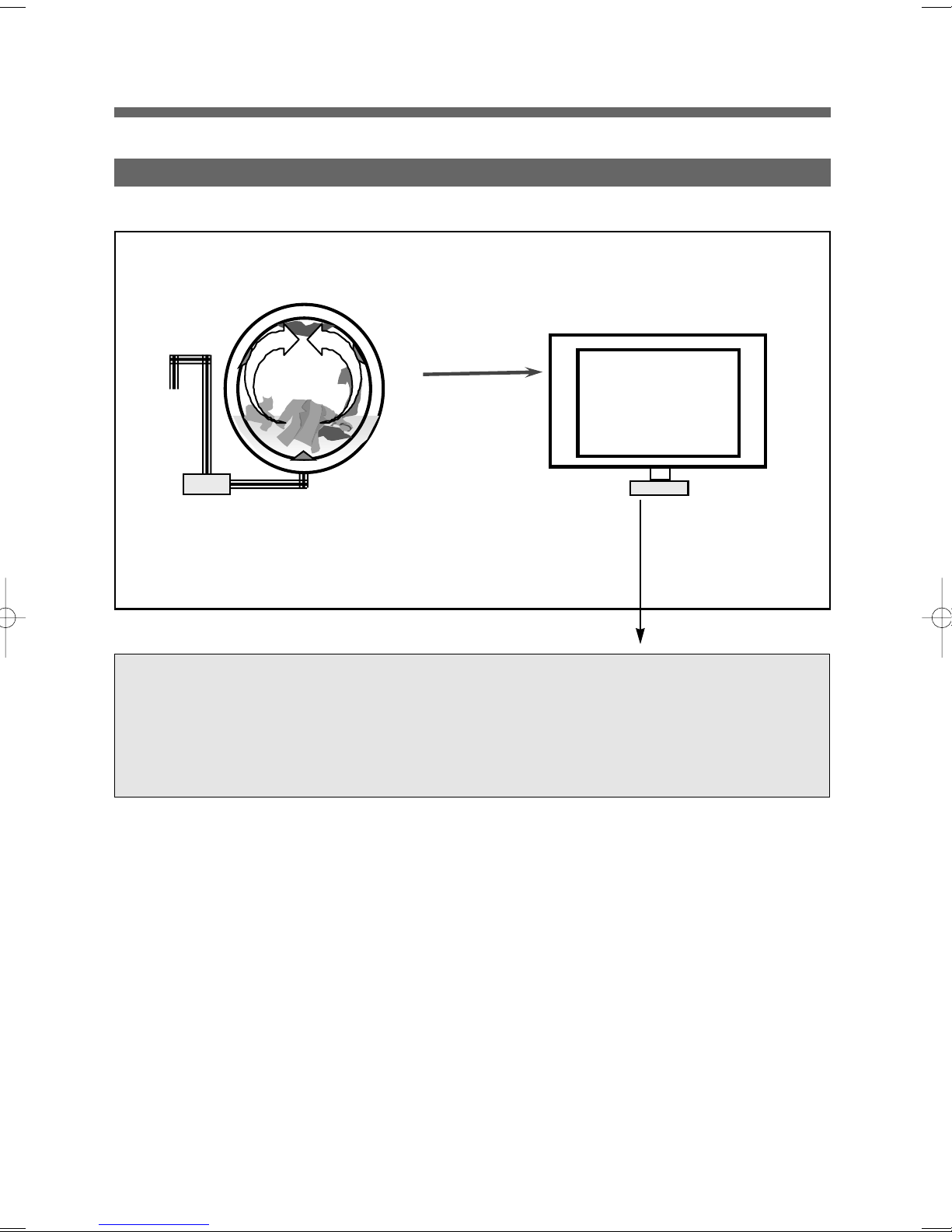
What is Drum Washing Machine?
"
1. Drum Washing Machine
Water consumption is reduced by using the power of the laundry falling (free-fall) created when rotating
the drum resembling a sieve net. With temperature control system, this drum washing machine saves
energy and improves washing performance at the same time.
2. Features of Drum Washing Machine
" Note that some features are options.
# Simultaneous supply of cold$hot water
As cold and hot water is supplied at the same time, heating time and energy is saved.
# Top-quality popup dial
The top-quality popup dial is used only during washing process.
# Dust filter
Filter to remove foreign substances, such as naps generated during washing, etc., is installed inside the
drum.
# DD inverter motor
The direct-drive type, of which motor is directly connected to drum without an interim clutch,
significantly reduces noise and vibration.
# Heating device is installed to enable boiling of the laundry.
# Large door creates grand appearance and makes it easy to put in and out the laundry.
# For pump drainage, the powerful pump speeds up drainage process.
2
3. Power System
Drainage Motor
BLDC Motor
Turbo
Drum
The
Laundry
#DD Control: Direct drive type of direct connection between drum and motor
#Rotation by powerful high-performance BLDC motor
#Pump drainage type for built-in installation
3

4. Major Functions of Drum Washing Machine
% Washing
When rotating drum after putting in the laundry and detergent into the drum, the laundry are rotated by
protrusions (lifters) attached inside the drum.
Washing is carried out with bending and impact actions generated by falling of the laundry to the top
part of drum.
& Rinsing
Rinsing cleanly washes out detergent and dirt removed from the laundry after washing cycle.
' Spin-drying
Weak, standard and strong cycles can be selected according to types of fabrics to be washed. Spindrying is carried out by rotation (the centrifugal force) of drum according to the designated speed.
( Drainage
Pump Drainage: Powerful pump for built-in installation and application of filter to remove foreign
substances
4
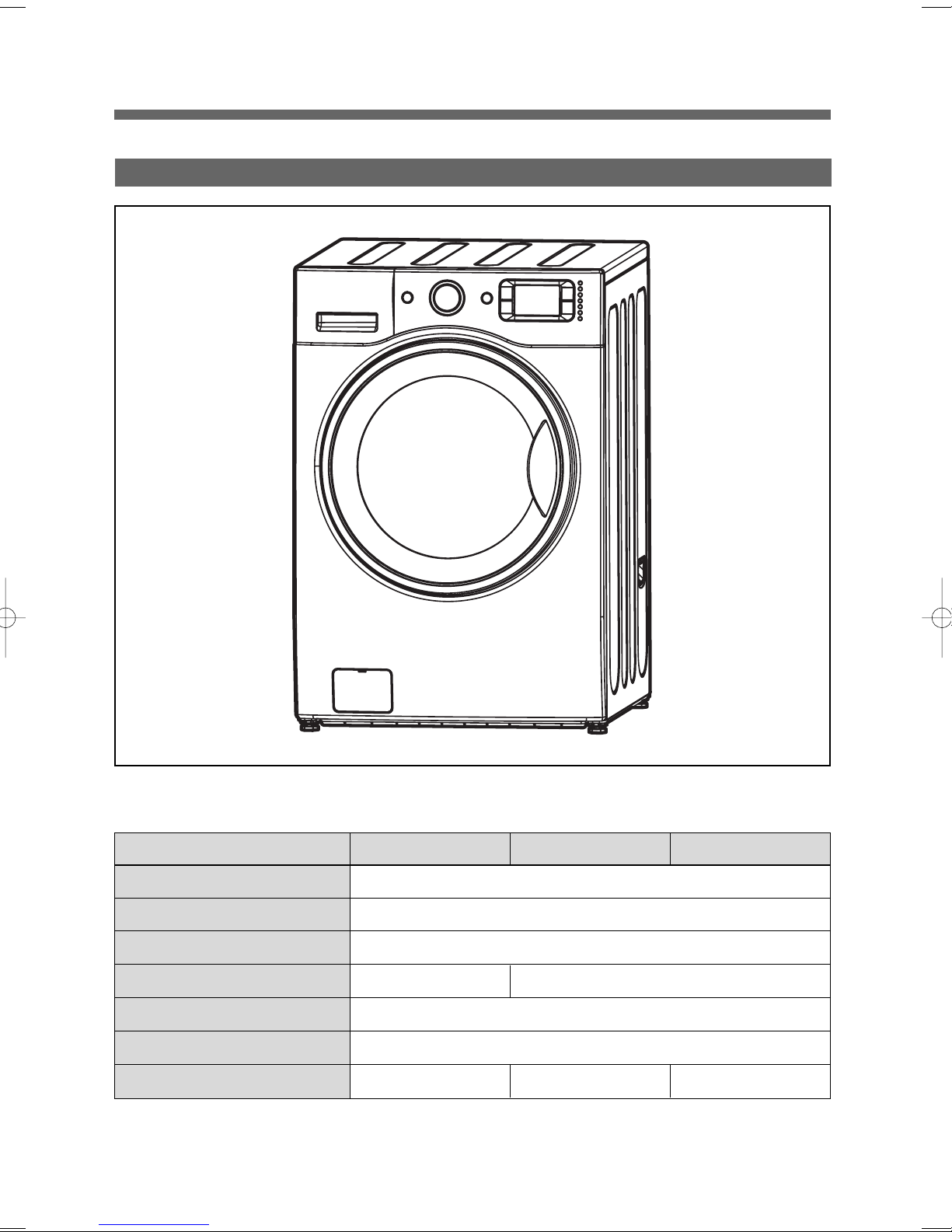
Product Spec
"
Product Spec.
MODEL DWD-WD125* DWD-WD135* DWD-WD135*S
Dimension (inches) 27 x 31.8 x 40.1 (W x D x H) (Door open D : 40.9)
Unit Weight (lbm) 198.4(Net) / 227(Gross)
Wash capacity 3.92 cu.ft. DOE, 4.5 cu.ft. IEC, 10.4kg
Spin Speed (RPM)
Operating Water Pressure 4.5~145 PSI (30~1000 kPa)
Electrical Spec. 120V / 60Hz, 10 A
Option Spec
1200 rpm max. 1300 rpm max.
XXSteam(900W)
5
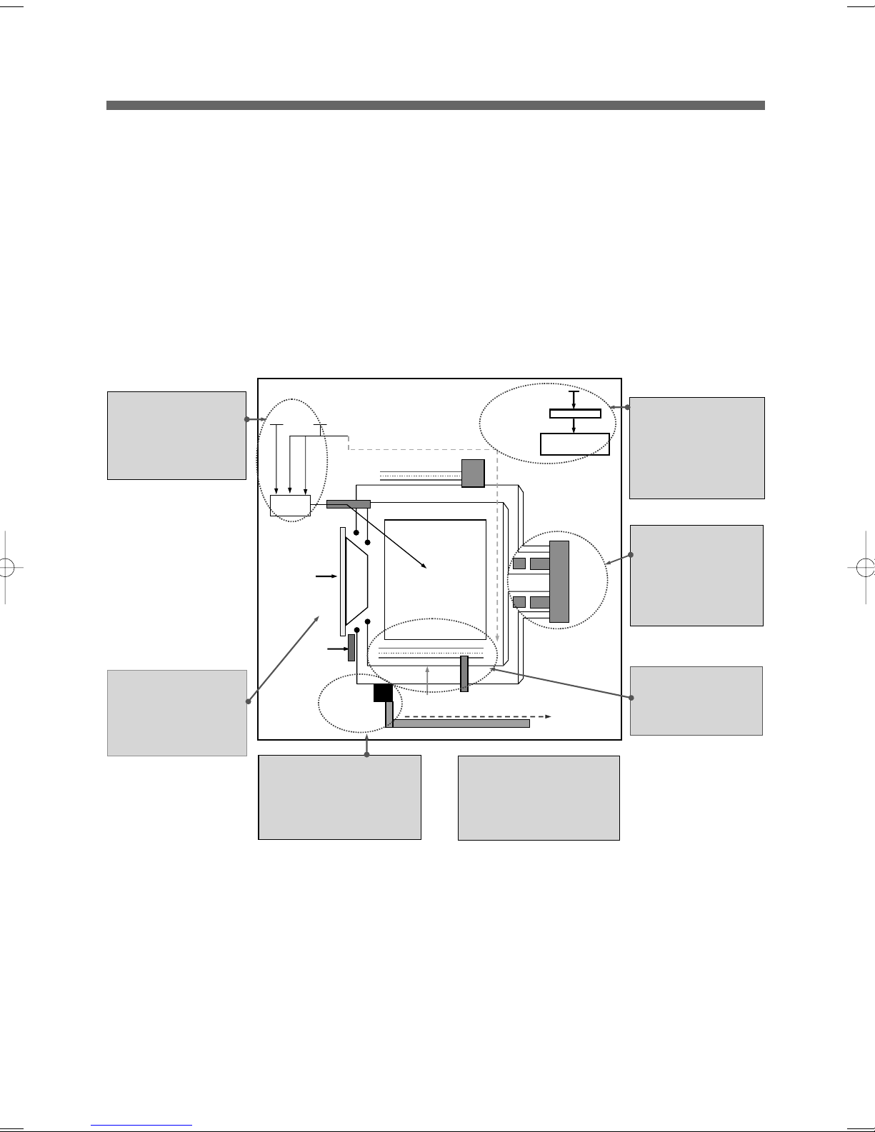
Operating Mechanism Diagram
"
4. WATER SUPPLY PART
4. WATER SUPPLY PART
• Cold Water: 3 holes
• Cold Water: 3 holes
Cold water, pre-washing
Cold water, pre-washing
• Hot Water: 1 hole
• Hot Water: 1 hole
• Water supply box, hose
• Water supply box, hose
5. DOOR
5. DOOR
• Door lock S/W
• Door lock S/W
• Lock hinge
- Lock hinge
• Door AS: Glass
• Door AS: Glass
• Gasket
• Gasket
Water
Supply
Delergent
Container
Thermister
Door
Door
Switch
Drainage
Pump
6. DRAINAGE PART
6. DRAINAGE PART
• Drainage pump
• Drainage pump
• Valve housing
• Valve housing
• Hose
• Hose
Drum
Washing
Heater
Electricity Input
Noise Filter
Thermister
7. SUPPORTER
7. SUPPORTER
• Base
• Base
• Damper AS: 4
• Damper AS: 4
• Spring: 2
• Spring: 2
Program
BLDC
Motor
1. CONTROL PART
1. CONTROL PART
• Main PCB
• Main PCB
• Front PCB
• Front PCB
• Harness
• Harness
• Noise filter
• Noise filter
• Power Cord: 15A
• Power Cord: 15A
2. DRIVING PART
2. DRIVING PART
• BLDC motor
• BLDC motor
• Drum
• Drum
• Bearing
• Bearing
• Spider/ shaft
• Spider/ shaft
• Tub
• Tub
• Weight balancer
• Weight balancer
3. HEATING PART
3. HEATING PART
• Water Heater: 1000W
• Water Heater: 1000W
• Washing temperature
• Washing temperature
sensor
sensor
6
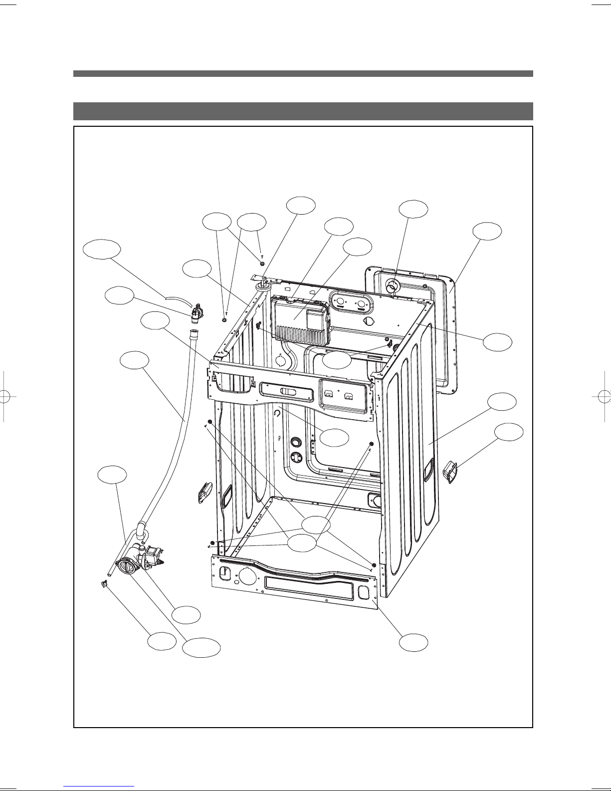
PARTS LIST FOR EACH ASSY
"
1. CABINET AS
C17-1
C17
C15
C14
C05
C03
C07
C08
C12
C18
C06
C20
C09
C11
C19
C04
C01
C10
C13
C16
C13-1
C07
C08
C02
7
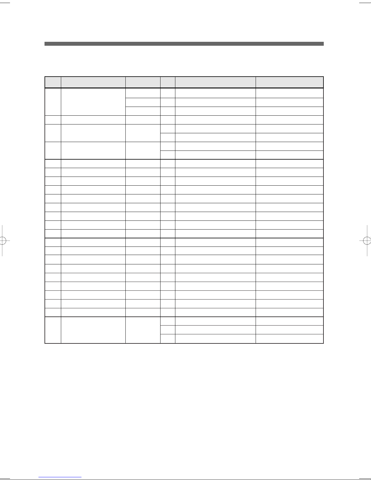
No. Part Name Part Code Qtt'y Specification Remark
- CABINET SUB AS 3610811950 1 13KG, PUMP, WHITE
3610811955 1 13KG, PUMP, PLATINUM
3610811956 1 13KG, PUMP, ROSE RED
C01 CABINET 3610811740 1 SGCC 0.8T PUMP WASHER • 1PIECE SVC PART
C02 FRAME LOWER 3612206700 1 SBHG 1.2T => CABINET SUB AS
C03 FRAME TOP L 3612206500 1 SGCC 1.6T
C04 FRAME TOP R 3612206600 1 SGCC 1.6T
C05 FRAME UPPER 3612208200 1 SGCC 1.2T
- SCREW TAPPING 7122401411 6 T2S TRS 4 x 14 MFZN Fix Frame Upper to Cabinet
C06 STOPPER SPRING 3615202200 2 POM
C07 FIXTURE PLATE 3612008000 8 POM
C08 SCREW TAPPING 7121401211 8 T2S PAN 4 x 12 MFZN
C09 NOZZLE AIR 3618103110 1 PP
C10 HANDLE CABINET 3612608100 2 PP, WHITE
2 PP, PLATINUM, RED
C11 COVER BACK AS 3611425530 1 COVER B + PAD + LABEL
- SCREW TAPPING 7122401411 4 T2S TRS 4 x 14 MFZN Fix Cober Back to Cabinet
C12 SENSOR PRESSURE 3614825220 1 DWD-130RP
- SCREW TAPPING 7122401411 2 T2S TRS 4 x 14 MFZN Fix Sensor Pressure to Cabinet
C13 UNIT DRAIN PUMP AS 36189L5600 1 UL.PLASET + HANYU AS 80W
C13-1 FILTER PUMP 3611910200 1 HANYU FILTER
- SCREW TAPPING 7122401411 2 T2S TRS 4 x 14 MFZN
Fix Drain Pump to Frame Lower
C14 HOSE DRAIN I 3613271300 1 ST+EL, 1010MM
- ABSORBER HOSE DRAIN 3610115600 1 T10, 60 x 130
- CLAMP HOSE 3611203900 2 SK5 D=26 Fix Drain I
C15 HOSE WATER REMAIN 3613272210 1 EPDM, UL 3T Round Bending
C16 CAP WATER REMAIN 3610916800 1 PP
C17 CUFF DRAIN HOSE 3616802600 1 PP, PUMP
C17-1 HOSE SIPHON 3613272210 1 EPDM, UL 3T L=270
- SCREW TAPPING 7122401411 1 T2S TRS 4 x 14 MFZN Fix Drain Hose to Cabinet
C18 PCB INVERTER AS 3610PCBF11 1 M_PCB+HAR+WIRE DWD-WD125*
3610PCBF06 1 M_PCB+HAR+WIRE DWD-WD135*
3610PCBF07 1 M_PCB+HAR+WIRE DWD-WD135*02
C19 COVER PCB M 3611427700 1 UL,ABS VE-0856, MAIN PCB
C20 HARNESS AS 3612796T00 1 UL, 13K Washer, Non-bubble D-WD125*, D-WD135*
3612796U00 1 UL, 13K Washer, Hot Steam D-WD135*02, D-WD135*02
- SCREW TAPPING 7122401411 1 T2S TRS 4 x 14 MFZN Fix PCB Main to Cabinet
- LOCK HARNESS M 3613802300 6 M Type(18 x 18), Nylon66 Cabinet rear
- LOCK HARNESS 3613802100 2 DASTL-20NA Frame Top right
- LABEL WIRING UL 3613557100 1 UL Only, Wiring diagram+Warning English&French
- SCREW TAPPING 7122401411 1 T2S TRS 4 x 14 MFZN Fix Cabinet F to Frame Lower
8
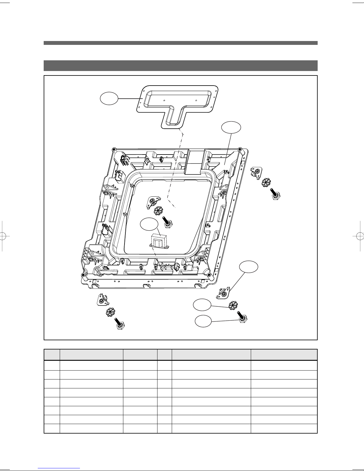
2. BASE U AS
B06
B01
B04
B03
B02
B5
No. Part Name Part Code Qtt'y Specification Remark
B01 REACTOR 52G043A110 1 RT-047(U), L=150
B02 BASE U 3610392700 1 PP
B03 SUPPORTER LEG 3615303600 4 PO+Coating 3.0T
B04 FIXTURE LEG 3612006400 4 ABS, DWD-100DR
B05 FOOT AS 3612100700 4
B06 PROTECTOR HEATER 3618304600 1 SECC 0.35T
- SCREW TAPPING 7122401411 4 T2S TRS 4x14 MFZN Fix Protector Heater to Base U
- SCREW TAPPING 7122401411 20 T2S TRS 4x14 MFZN Fix Base U to Cabinet
Foot+Special bolt, Double insert type Hybra-Nylon66
9
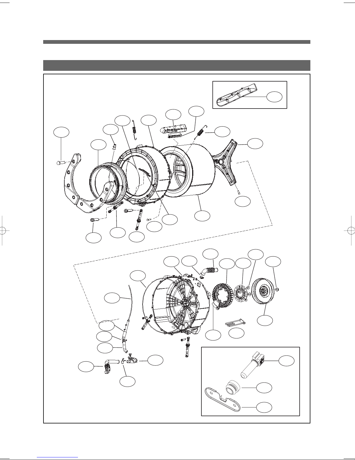
3. TUB AS
D06
T01
T03
T12
T04
T11
T05
T10
T21
T06
T07
D04
T09
T20
T23
D05
D01
T22
T08
T24
D03
T26
D02
T27
T29
T15
T18
T17
T16
T13
T14
T19
10
T25
T28
T30
T33
T32
T31
No. Part Name Part Code Qtt'y Specification Remark
T01 SPECIAL SCREW 3616029400 8 SWCH 8.5 x 30 Fix Balancer W. to Tub F
T02
BALANCER WEIGHT AS(L)
BALANCER WEIGHT AS(R)
3616110100 1 13kg DRUM
3616110200 1 13kg DRUM
T03 GASKET AS 3612322000 1 EPDM, Wash-only, Nozzle shower
T04 NOZZLE SHOWER 3618104000 1 PP
T05 CLAMP GASKET AS 3611205300 1 Gasket, 13kg Drum
T06 TUB FRONT 3618828Y00 1 FRPP, 13kg Drum
T07 SPECIAL SCREW(TUB) 3616029800 15 SWCH 6.5 x 30 Fix Tub F & R
T08 SPRING SUSPENSION 3615114800 2 13kg DRUM
T09 FIXTURE HEATER 3612006700 1 STS 430
T10 DAMPER FRICTION 361A700300 2
T11 DAMPER FRICTION 361A700110 2
AWECO, HP3 60N/9MM BUFFER 4,0
70N AKS ST=170-260 DL=197.5 LOW NOISE
Tub F & R right
Tub F & R left
T12 DAMPER PIN 361A700200 8 AKS D=14.5 Tub & Base U
T13 HOSE DRAIN 3613269000 1 EPDM,PUMP
T14 CLAMP HOSE 3611203410 2 SK5, D=33
T15 HOSE AIR PRESSURE 3613270600 1 ID=4,OD=8,L=1000MM
T16 HOSE AIR TRAP 3613269700 1 EPDM, 13kg Drum
T17 CLAMP HOSE 3611204700 2 D26
T18 AIR TRAP 361A500101 1 PP
T19 DRAIN HOUSING I 36196TAM00 1 PP,PUMP 1 PIECE SVC PART
T20 TUB REAR AS 36100E2W00 1 DWD-WD113*, DWD-WD123*
T21 GASKET TUB 3612322100 1 EPDM FORM, 13KG DRUM
T22 HOSE AIR 3613266300 1 EPDM, DWD-100DR
T23 CLAMP HOSE 3611203400 2 SK5, MFZN,D=35
T24 UNIT STATOR BLDC 36189L4840 1
30T,36SLOT,2SENSOR,WS2A30G011
1 PIECE SVC PART
T25 BLDC HALL IC 3626D01002 1 STATOR PCB HOLDER AS(SVC)
T26 BRACKET HOUSING 3610609700 1 GI 2.3T
T27 SPECIAL BOLT AS 3616063400 6 SWCH M8+SILOCK, 58MM Fix Stator & Tub R
T28 UNIT ROTOR BLDC 36189L4900 1
T29 SPECIAL BOLT AS 3616029600 1
T30 HEATER WASH 3612801740 1
MAGNET24,SERRATION,WR1238F001
SWCH 10*30,F/L BOLT S.P/W SEAL LOCK
UL.120V1.0KW6.7W/SQ.SUS.1R3A515003.L/W.
DWD-WD113*, DWD-WD123*
T31 BRACKET THERMISTOR 3610610600 1 SGCC 0.8T, Non-Heater DWD-WD103*01
T32 THERMISTOR WASH 361AAAAB20 1 UL.R80:1.704K.R25:11.981K DWD-WD113*01
T33 PACKING THERMISTOR 3614011400 1 EPDM, Non-Heater
D01 DRUM SUB AS 3617008X00 1 SUS, 13kg 1 PIECE SVC PART
D02 SPIDER AS 361A300600 1 13kg, ALDC+S45C
D03 SPECIAL SCREW(SPIDER) 3616029500 6 STS 430, 8 x 25
D04 LIFTER BODY 361A400700 3 PP, 13kg Drum 1st Lifter
D05 CAP FILTER 3610917310 3 ABS, NON-NANO, 13kg 1 PIECE SVC PART
FILTER 3611908410 3 ABS, NON-NANO, 13kg (OPTION)
FILTER NET 3611908500 3 SUS, FILTER
D06 LIFTER WASH 361A401400 3 NON-NANO, 1 PIECE TWIST 3rd Lifter
11
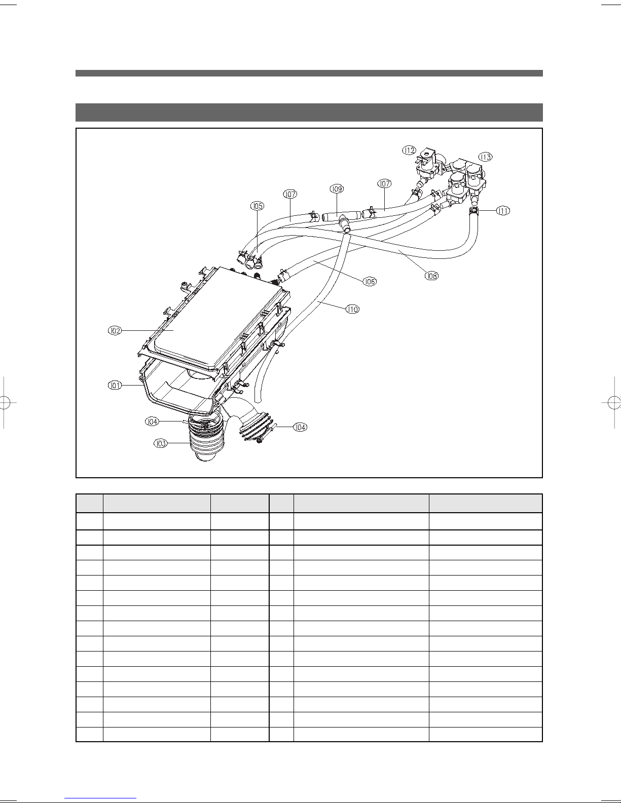
4-1 INLET BOX AS(NON-STEAM)
No. Part Name Part Code Qtt'y Specification Remark
I01 INLETBOX 3617510800 1 PP
I02 NOZZLE AS 3618104800 1 WD1131'S, Top+Under
I03 HOSE INLET 3613270300 1 EPDM
I04 CLAMP AS 3611203200 2 ID=60, WIRE+GUIDE+BOLT+NUT
I05 HOSE WATER SUPPLY 3613270920 1 EPDM ID=9.5 OD=15.5 L=410mm From Valve Inlet to HOT nozzle
I06 HOSE WATER SUPPLY 3613270920 1 EPDM ID=9.5 OD=15.5 L=380mm
I07 HOSE WATER SUPPLY 3613270920 2 EPDM ID=9.5 OD=15.5 L=230mm
I08 HOSE WATER SUPPLY 3613270920 1 EPDM ID=9.5 OD=15.5 L=530mm
I09 PIPE JOINT HOSE INLET 3614413300 1 PP
I10 HOSE SHOWER 3613270130 1 EPDM ID=8.5 L=550mm
I11 CLAMP HOSE 3611205810 1 D-WD113'S ID14.3 W10 0.9T WH
I12 VALVE INLET 3615416700 1 UL.120V60HZ.BITRON.1WAY HOT
I13 VALVE INLET 3615416930 1 UL.120V60HZ.BITRON.3WAY COLD
- SCREW TAPPING 7002400811 4 TRS 4X8 MFZN Fix Valve Inlet to Cabinet
- SCREW TAPPING 7122401411 1 T2S TRS 4X14 MFZN Fix Inletbox to Frame T(Side)
From Valve Inlet to MAIN nozzle
From Valve Inlet to PRE-WASH nozzle
From Valve Inlet to BLEACH nozzle
12
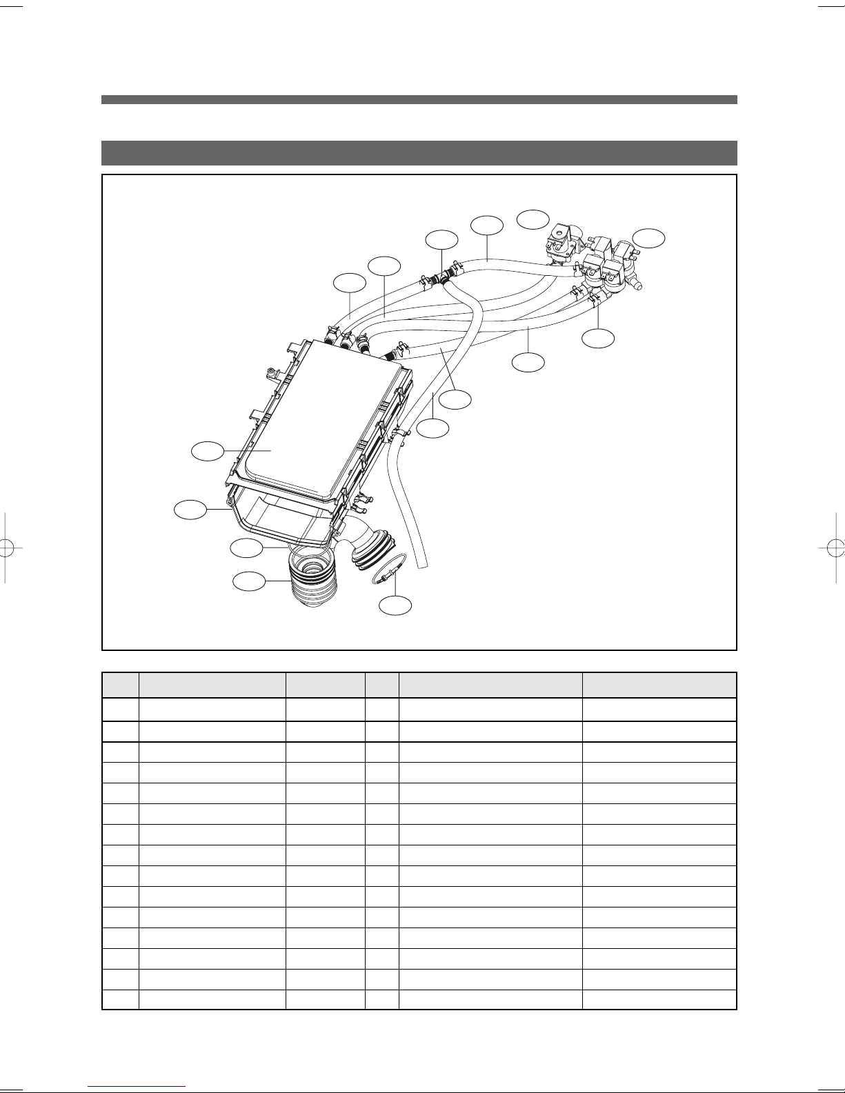
4-2 INLET BOX AS(HOT-STEAM)
I01
I02
I04
I03
I07
I05
I04
I10
I09
I06
I07
I12
I13
I11
I08
No. Part Name Part Code Qtt'y Specification Remark
I01 INLETBOX 3617510800 1 PP
I02 NOZZLE AS 3618104800 1 WD1131'S, Top+Under
I03 HOSE INLET 3613270300 1 EPDM
I04 CLAMP AS 3611203200 2 ID=60, WIRE+GUIDE+BOLT+NUT
I05 HOSE WATER SUPPLY 3613270920 1 EPDM ID=9.5 OD=15.5 L=410mm From Valve Inlet to HOT nozzle
I06 HOSE WATER SUPPLY 3613270920 1 EPDM ID=9.5 OD=15.5 L=430mm
I07 HOSE WATER SUPPLY 3613270920 2 EPDM ID=9.5 OD=15.5 L=220mm
I08 HOSE WATER SUPPLY 3613270920 1 EPDM ID=9.5 OD=15.5 L=350mm
I09 PIPE JOINT HOSE INLET 3614413300 1 PP
I10 HOSE SHOWER 3613270130 1 EPDM ID=8.5 L=550mm
I11 CLAMP HOSE 3611205810 1 D-WD113'S ID14.3 W10 0.9T WH
I12 VALVE INLET 3615416700 1 UL.120V60HZ.BITRON.1WAY HOT
I13 VALVE INLET 3615416930 1 UL.120V60HZ.BITRON.3WAY COLD
- SCREW TAPPING 7002400811 4 TRS 4X8 MFZN Fix Valve Inlet to Cabinet
- SCREW TAPPING 7122401411 1 T2S TRS 4X14 MFZN Fix Inletbox to Frame T(Side)
From Valve Inlet to MAIN nozzle
From Valve Inlet to PRE-WASH nozzle
From Valve Inlet to BLEACH nozzle
13
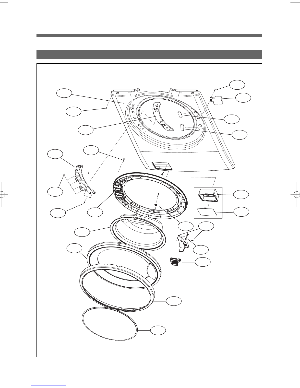
5. CABINET FRONT ASS'Y
F01
F21
F20
F19
F03
F09
F10
F18
F11
F02
F07
F12
F05
F06
F04
F22
F23
F16
F15
F14
F24
F08
14
No. Part Name Part Code Qtt'y Specification Remark
F01 CABINET F SUB AS 3610811310 1 13KG, PUMP, WHITE
3610811321 1 13KG, PUMP, PLATINUM
3610811322 1 13KG, PUMP, ROSE RED
F02 SUPPORTER HINGE 3615304001 1 SGCC 1.2T
F03 LABEL SAFETY R 3613555800 1 PET, DOOR SAFETY,UL
1 PET, DOOR SAFETY,UL, RH Right Handle type
F04 LABEL WARNING 3613558500 1 PET,SILVER,DOOR WARNING,UL
1 PET, DOOR WARNING,UL, RH Right Handle type
F05 FRAME DOOR IN 3612210700 1 PP(Heat resisting)
F06 STOPPER DOOR 3615202300 1 PP(Heat resisting)
F07 DOOR GLASS 361A110600 1 GLASS
F08 PROTECTOR GLASS 3618304300 1 ABS(Transparent)
F09 HINGE DOOR AS 3612903900 1 13K WASHER,ALDC
F10 CAP HINGE DOOR 3610916500 4 POM
F11 FRAME DOOR OUT 3612210800 1 13K WASHER,ALDC
F12 SCREW TAPPING 7115402029 16 T1S FLT 4*20 STS430 NATURAL
F13 COVER HANDLE 3611429300 1 ABS WHITE
F14 HANDLE DOOR 3612612100 1 ABS
F15 HOOK DOOR 3613100800 1 ZNDC
F16 SPRING HOOK 3615113700 2 SUS ID=4.3,NI=7,D="0.9
F17 PIN HANDLE 3618200100 1 SUS, D3.0
F18 SCREW TAPPING 3616051229 4 STS430 F/L BOLT(SE) 5*12
F19 SWITCH DOOR LOCK 3619046410 1
F20 SCREW TAPPING 7122401608 2 T2S TRS 4 x 16 SUS 430
DF F11 110 125V 16A PTC-SOLENOID
For fixing Door S/W to Cabinet F
F21 SCREW TAPPING 7122401411 4 T2S TRS 4 x 14 MFZN For fixing Cabinet F to Cabinet
F22 CASE PUMP 3611141400 1 PP
F23 COVER PUMP 3611426800 1 ABS, WHITE
1 ABS, PLATINUM
1 ABS, RED
15
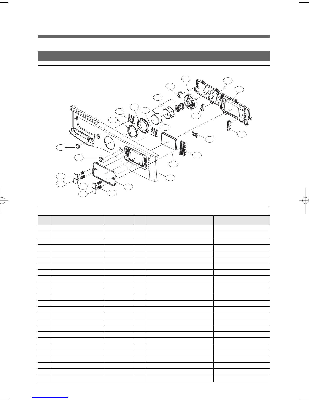
6. PANEL F AS
F02
F05
F06
F03
F07
F08
F15
F09
F10
F04
F16
F19
F18
F18
F11
F18
F11
F14
F13
F12
F01
F22
F21
F20
No. Part Name Part Code Qtt'y Specification Remark
- PANEL-F AS PRPAFR9Z10 1 DWD-WD1352S/1352
F01 PANEL-F 3614289600 1 ABS + SILK Printing
F02 DECO BUTTON POWER 3611692120 1 ABS(GILDING/SPRAY)
F03 DECO BUTTON START 3611692220 1 ABS(GILDING/SPRAY)
F04 DECO WINDOW 3611692420 1 ABS(GILDING/SPRAY)
F05 BUTTON FUNCTION WASH 3616640700 1 ABS + SILK Printing
F06 BUTTON FUNCTION SPIN 3616640800 1 ABS + SILK Printing
F07 BUTTON FUNCTION SOIL 3616640900 1 ABS + SILK Printing
F08 BUTTON FUNCTION BEEP 3616641000 1 ABS + SILK Printing
F09 SPRING BUTTON 3615116200 4 SUS 0.7PI D=12.3 L=15
F10 BUTTON POWER AS 3616640550 1 Transparent PC
F11 BUTTON START AS 3616640650 1 Transparent PC
F12 WINDOW DISPLAY 3615508300 1 Transparent ABS TR 558
F13 BUTTON OPTION 3616641200 1 Transparent ABS TR 558
F14 BUTTON TIME 3616641100 1 ABS
F15 WINDOW COURSE 3615508200 1 Transparent ABS TR 558
F16 DECO COURSE 3611692310 1 ABS(GILDING/SPRAY)
F17 BUTTON DIAL AS 3616643300 1 Push-Pull Type
F18 HOLDER POWER 3613056800 2 ABS(Anti-flammable, VE-0856)
F19 HOLDER COURSE 3613056900 1 ABS(Anti-flammable, VE-0856)
F20 HOLDER OPTION 3613057000 1 ABS(Anti-flammable, VE-0856)
F21 CUSTOM LED 3610019900 1 18:88 LED
F22 CASE PCB F 3611148800 1 ABS(Anti-flammable, VE-0856)
- PCB AS PRPSSWAD36 1 DWD-WD1352S/1352
- SCREW TAPPING 7122401211 7 T2 TRS 4x12 MFZN
16
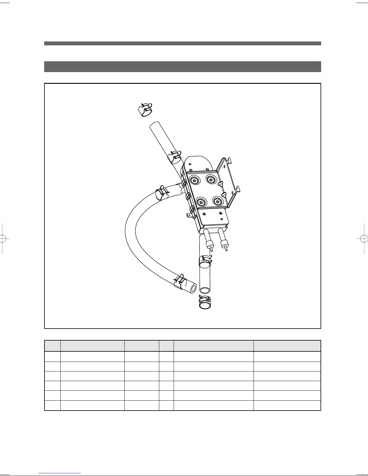
7. UNIT STEAM WASHER AS
No. Part Name Part Code Qtt'y Specification Remark
- UNIT STEAM WASHER AS 3619606800 1 D-WD1351,HOT STEAM AS
S01 UNIT STEAM AS 3619606700 1 D-WD1351,STEAM AS
S02 HOSE SPRAY 3613275100 0.245 UL, SILICON, ID=9.5, OD=16.5
S03 HOSE SPRAY 3613275100 0.73 UL, SILICON, ID=9.5, OD=16.5
S04 HOSE SPRAY 3613275100 0.62 UL, SILICON, ID=9.5, OD=16.5
S05 CLAMP HOSE 3611205830 6 HOT SPRAY,ID=15.5
17
rum Wa
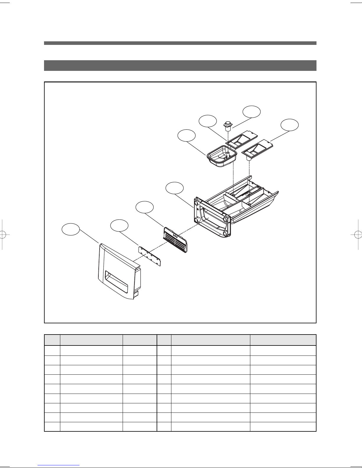
8. CASE DETERGENT AS
A02
A05
A04
A06
A03
A08
A01
No. Part Name Part Code Qtt'y Specification Remark
- CASE DETERGENT AS 3611149000 1 DWD-WD1151
A01 CASE HANDLE 3611148700 1 ABS
A02 CASE DETERGENT 3611145600 1 PP
A03 CAP SOFTENER 3610917800 1 PP
A04 CAP BLEACH 3610917900 1 PP
A05 CASE LIQUID 3611145700 1
A06 CAP LIQUID 3610918000 1
A07 CUSHION HANDLE 3611571900 1 SILICON, WD1151
A08 DECO CASE HANDLE 3611691900 1 ABS, CROM_BASE
A07
18
rum Wa
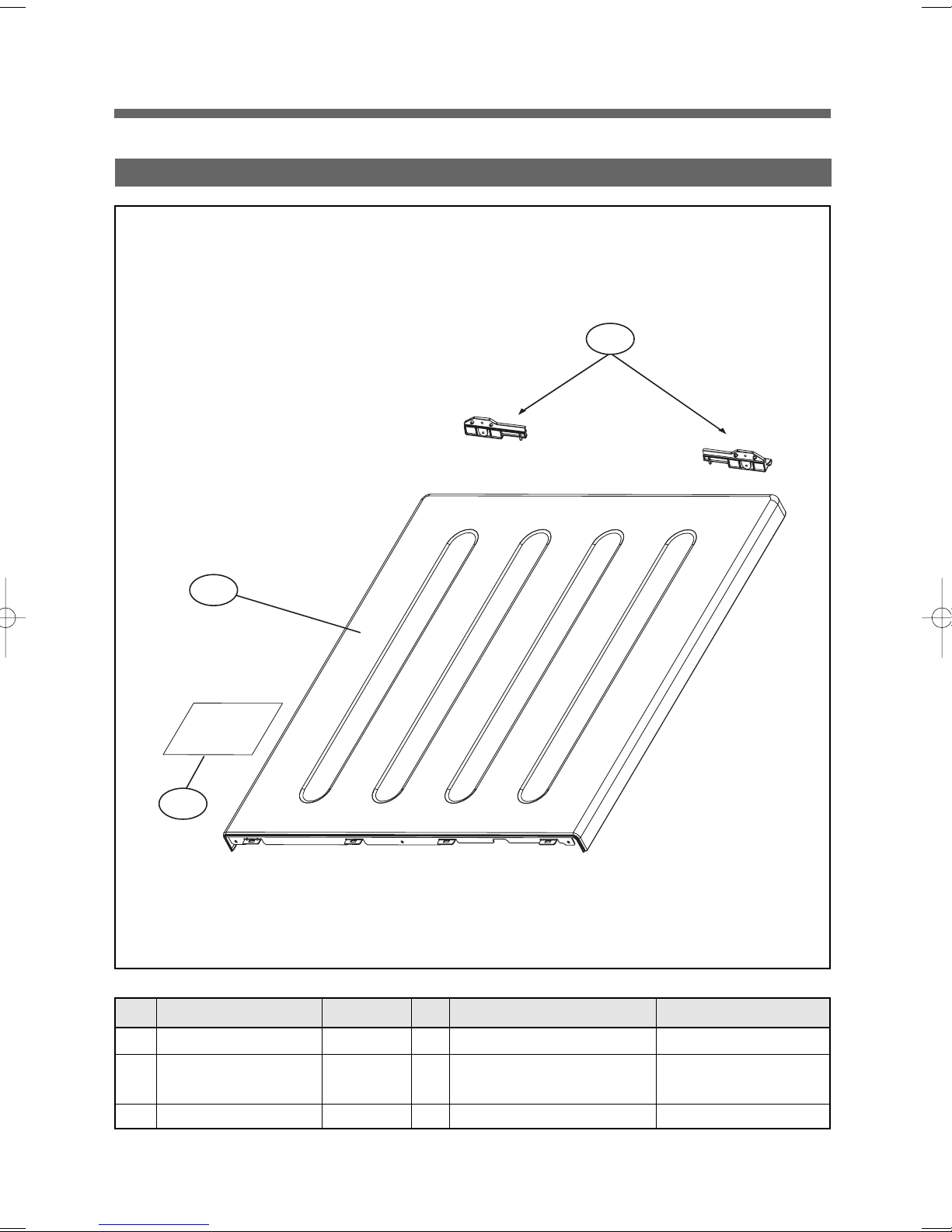
9. PLATE T AS
T02
T01
T03
No. Part Name Part Code Qtt'y Specification Remark
T01 PLATE TOP AS PRMACA3R00 1 SECD 1.2T + SPRAY
T02 HANDLE REAR 3615304100 2 ABS
(PLATE SUPPOTER)
- SCREW TAPPING 7122401411 4 T2S TRS 4x14 MFZN
19
rum Wa
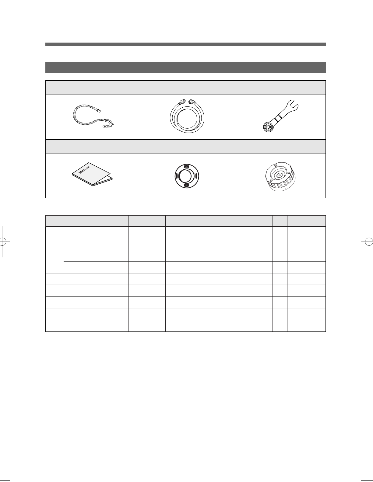
10. ACCESSORY
A01 A02 A03
A04 A05 A06
NNoo.. PPaarrtt NNaammee PPaarrtt CCooddee DDeessccrriippttiioonnss QQtt''yy RReemmaarrkkss
A01 HOSE DRAIN O AS 3613268500 DWD-800W, L=1,500 1
GUIDE DRAIN HOSE 3612502300 PP 1
A02 HOSE INLET AS 3613271500 REFLEX, PVC 1.3M 1 Cold
HOSE INLET AS 3613271510 REFLEX, PVC 1.3M 1 Hot
A03 UNIT SVC WRENCH 36189L3X00 PO+Coating, 2.3T DWD-110RP 1
A04 MANUAL OWNERS 4589A61600 ASKO Manual 1
A05 CAP HOLDER 3610916400 PP, DWD-10RP 4
A06 UNIT LEVELER AS 36189L4M00 FOOT 1 + LEG 1 1 Option
36189L4M10 FOOT 1 + LEG 2 1 Option
English & French
20
Control Part Function Spec
"
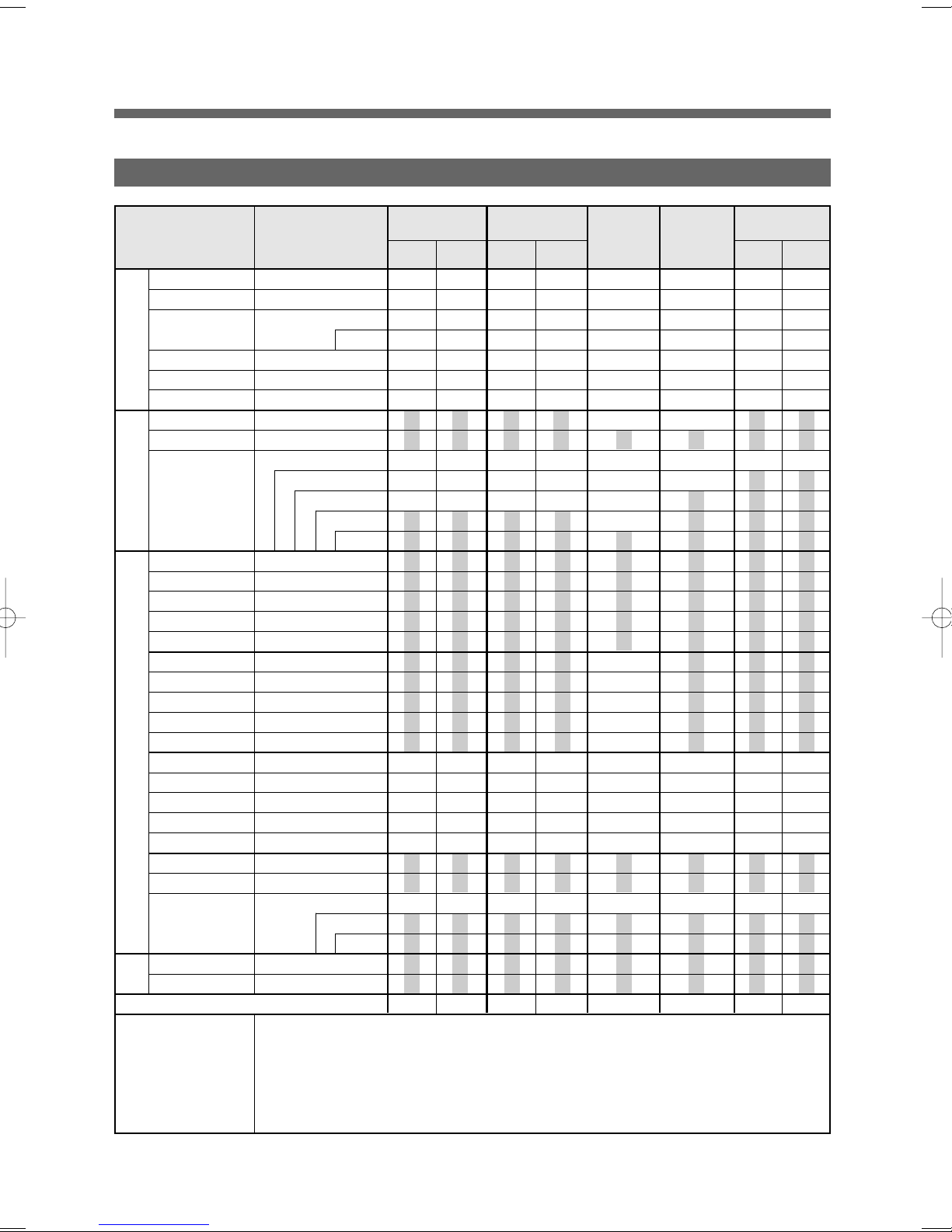
1. SEQUENCE CHART
CCllaassssiiffiiccaattiioonn PPrroocceessssiinngg TTiimmee
Small Low Small Low Small Low
PP
rr
ee
WW
aa
ss
hh
WW
aa
ss
hh
RR
ii
nn
ss
ee
SS
pp
ii
nn
EEnndd
Sensing 10sec
Water Supply 2min
Pre-Wash 10min
8min
Drain 1min
Balancing Spin 2min
Middle Spin 3min
Sensing 20sec
Water Supply 2min
"Main-Wash 1 50min 53min 72min
(Heating)" 45min 35min
30min 18min 22min 16min 17min
25min 8min
15min
Drain 1min
Balancing Spin 2min
Middle Spin 3min
Water Supply 2min
Rinse 1 4min
Drain 1min
Balancing Spin 2min
Middle Spin 3min
Water Supply 2min
Rinse 2 4min
Drain 1min
Balancing Spin 2min
Middle Spin 3min
Water Supply 2min
Rinse 3 4min
Drain 1min
Balancing Spin 2min
Spin 9min
7min
6min
Clothes Release 60sec
End 10sec
Remain Time Display 55 59 53 54 32 1:12 1:30 1:34
NOTE
DDeelliiccaattee HHeeaavvyy dduuttyy
SSaanniittaarryyNNoorrmmaall CCoottttoonn
21
rum Wa
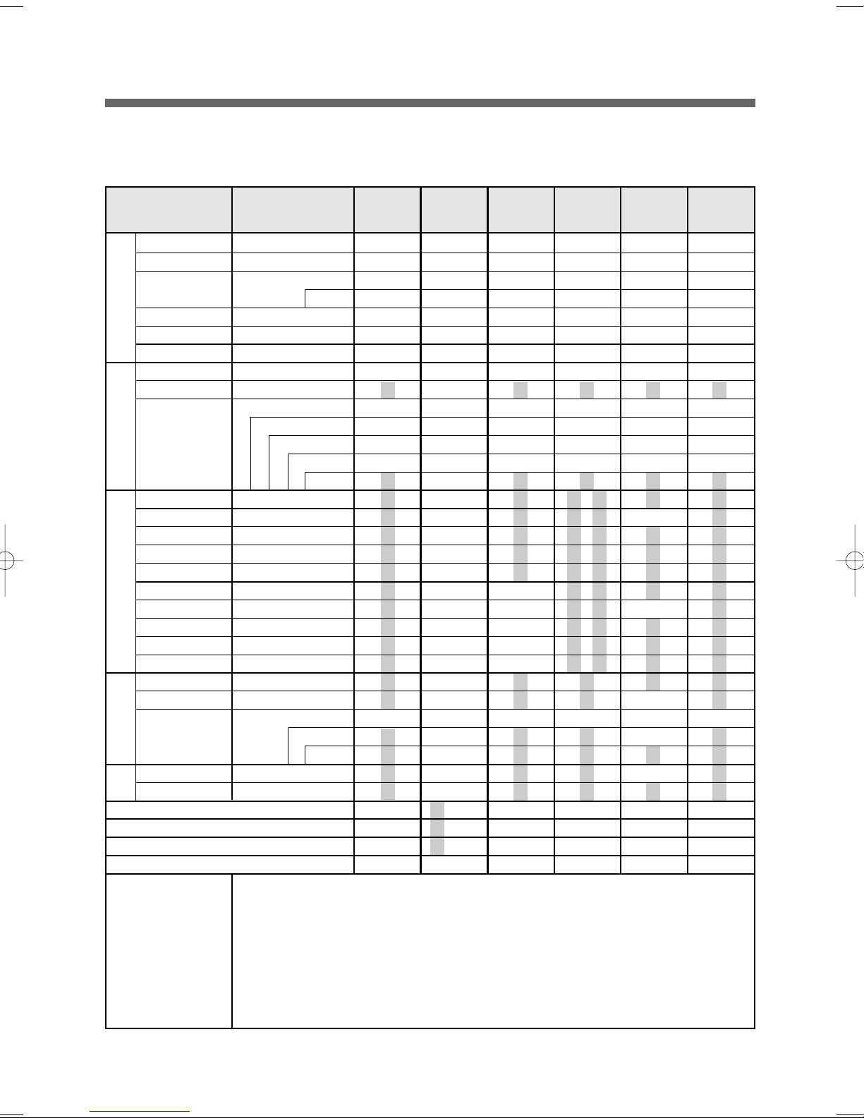
CCllaassssiiffiiccaattiioonn PPrroocceessssiinngg TTiimmee
PP
rr
ee
WW
aa
ss
hh
WW
aa
ss
hh
RR
ii
nn
ss
ee
SS
pp
ii
nn
EEnndd
Steam Pre-Heating 30 s
Steam 5min
Cooling 10min
Sensing 10sec
Water Supply 2min
Pre-Wash 10min
Drain 1min
Balancing Spin 2min
Middle Spin 3min
Sensing 20sec
Water Supply 2min
"Main-Wash 1 50min
(Heating)" 45min
30min Soak 30min
25min 22min 19min 19min
15min 8min 13min
Drain 1min
Balancing Spin 2min
Middle Spin 3min
Water Supply 2min
Rinse 1 4min 3min
Drain 1min
Balancing Spin 2min
Middle Spin 3min
Water Supply 2min
Rinse 2 4min 3min
Drain 1min
Balancing Spin 2min
Spin 9min
Clothes Release 60sec
End 10sec
Remain Time Display 59 16 33 1:20 45 1:20
NOTE
PPeerrmm PPrreessss
WWDD11335522
8min
7min
6min 5min
SStteeaamm ffrreesshh
WWDD11335522SS
SSppeeeedd
WWaasshh
BBaabbyy ccaarree GGyymm sshhooeess DDrruumm--cc
22
2. Composition per Function
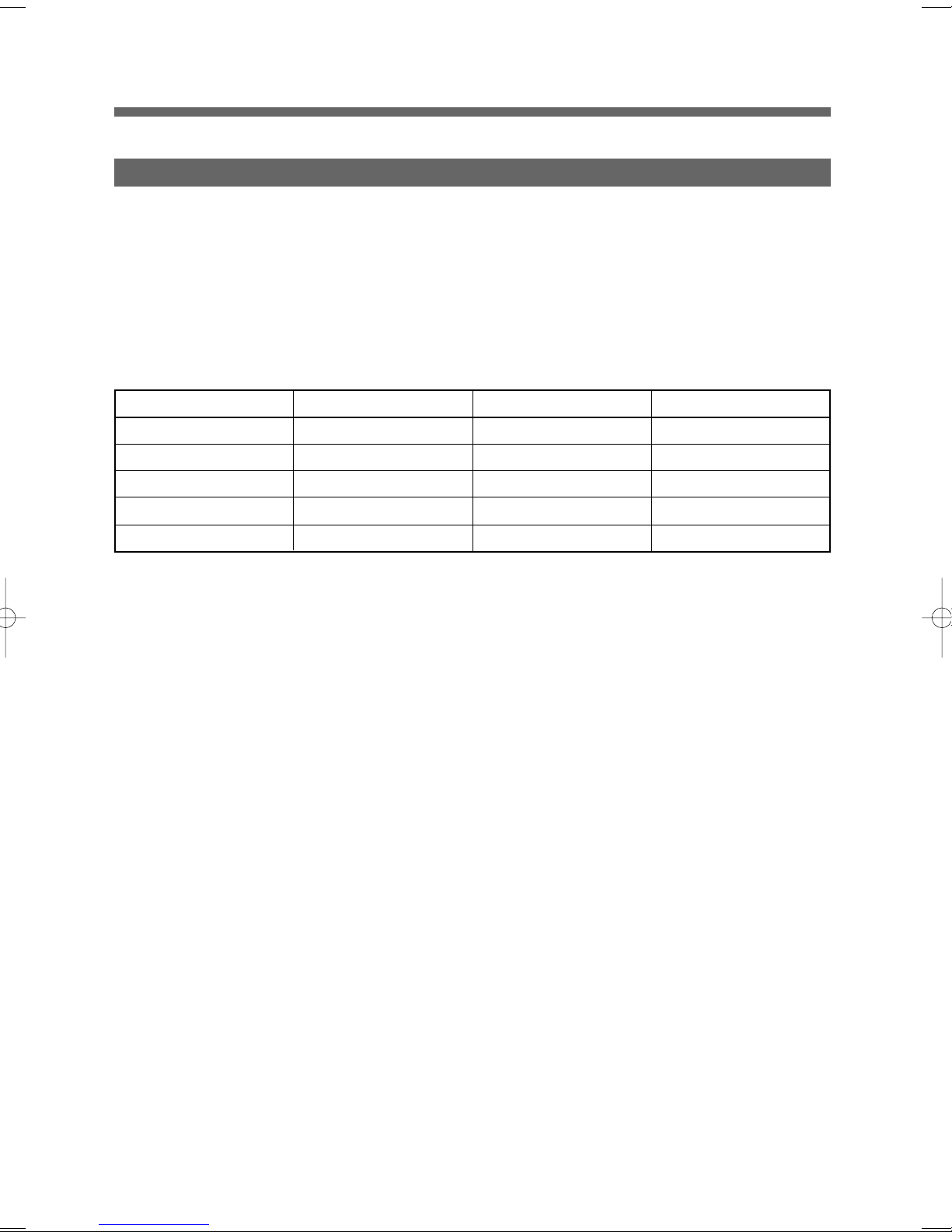
2-1. Water Supply
1) Water Temperature Selection
Water supply algorithm differs according to water temperature selected among 5 levels.
In other temperatures, with the exception of cold water, constant temperature control is executed.
Cold water and hot water operation is carried out in turn according to the target temperature.
Water T emp. T arget T emp. T arget 1 T arget 2
Extra Hot/Cold 67) 67) 70)
Hot/Cold 35) 39) 36)
Warm/W arm 30) 29) 31)
Warm/Cold 30) 29) 31)
Cold/Cold - - -
2) For Cold/Cold, valve operation does not change according to temperature and only the time unit of cold
on for 7sec and off for 9sec is set to supply cold water per each unit of 16sec.
% Pre-wash V/V Operation
On for 3sec/ off for 2sec - Twice: Removing residual detergent from water supply box
& During the intial water supply for washing water is received 5mm higher than the set level.
3) How to Insert Bleach
% During Washing
Operation for 12sec after 3-minute washing in wool, delicate and speed wash courses
Operation for 12sec after 5-minute washing in cotton course
Operation for 12sec after skipping soaking and 4-minute of washing in Drum-cleaning course
Operation for 12sec after soaking and 4- minute of washing in Drum-cleaning course
23
rum Wa
2-2. Drainage
1) Pump Operation - Washing cycl FUNCIONAMIENTO DE LA BOMBA CICLO DE LAVADO
% Before Drainage Completion: Pump continuously on ANTES DE TERMINAR EL DRENADO LA BOMBA CONTINUA
& Spin-drying Cycle after Drainage Completion SPIN-CLICO DE SECADO TERMINACION DEL DRENADO
: On for 18sec and off for 3sec POR PERIODOS DE 18 SEG TRABAJANDO Y 3 SEC EN REPOSO
2-3. Sensor Detection SENSOR DE DETECCION
1) Water Level Sensor SENSOR DE NIVEL DE AGUA
* Water Level Data DATOS SOBRE EL NIVEL DE AGUA
Classification ALTURA Frequency
Water Level (mm) (KHz)
Especificacion-minima 130 24.62
Spec. baja 130 24.62
Lavado-Minimo 130 24.38
Washing Low 130 24.09
Standard Rinsing 160 24.27
Rinsing 160 23.64
Additional Rinsing 175 24.01
Tub Washing 195 23.77
Overflow 260 22.6
Safety 125 24.7
Reset 125 24.68
Remarks
24
 Loading...