

Page 1

Service Manual
Microwave Oven
Model: KOC-970T1S
KOC-970T2S
KOC-980T10S
KOC-980T20S
DAEWOO ELECTRONICS CO., LTD.
Page 2

PRECAUTIONS TO BE OBSERVED BEFORE AND
DURING SERVICING TO AVOID POSSIBLE
EXPOSURE TO EXCESSIVE MICROWAV E ENERGY
(a) Do not operate or allow the oven to be operated with the door open.
(b) Make the following safety checks on all ovens to be serviced before activating the magnetron or other microwave
source, and make repairs as necessary: (1) Interlock operation, (2) Proper door closing, (3) Seal and sealing
surfaces (arcing, wear, and other damage), (4) Damage to or loosening of hinges and latches, (5) Evidence of
dropping or abuse.
(c) Before turning on power to the microwave oven for any service test or inspection within the microwave
generating compartments, check the magnetron, wave guide or transmission line, and cavity for proper
alignment, integrity, and connections.
(d) A ny defective or misadjusted components in the interlock, monitor, door seal, and microwave generation and
transmission systems shall be repaired, replaced, or adjusted by procedures described in this manual before the
oven is released to the owner.
(e) A microwave leakage check to verify compliance with the Federal performance standard should be performed on
each oven prior to release to the owner.
SAFETY AND PRECAUTIONS ........................................................................................................ 2
SPECIFICATIONS ................................................................................................................ ............ 3
EXTERNAL VIEW ............................................................................................................................ 4
1. OUTER DIMENSION .......................................................................... .......................................... 4
2. FEATURE DIAGRAM .................................................................................................................. 5
INSTALLATION ................................................................................................................................ 7
CONTROL PANEL ........................................................................................................................... 8
DISASSEMBLY AND ASSEMBLY .................................................................................................. 9
INTERLOCK MECHANISM AND ADJUSTMENT ............................... ... ..................... .................... 18
TROUBLE SHOOTING GUIDE ........................................................................................................ 19
MEASUREMENT AND TEST ........................................................................................................... 2 5
1. MEASUREMENT OF THE MICROWAVE POWER OUTPUT ..................................................... 25
2. ELECTRICAL CONTINUITY CHECK OF INTERLOCK SWITCH ................................................ 26
3. MICROWAVE RADIATION TEST ................................................................................................ 27
4. COMPONENT TEST PROCEDURE ............................................................................................ 28
WIRING DIAGRAM .................... ... ... ..................... ...................... ..................... ..................... ........... 29
SCHEMATIC DIAGRAM ........................ ... ..................... ........................................ ......................... . 30
EXPLODED VIEWS AND PARTS LIST ........................................................................................... 33
PRINTED WIRING BOARD ............................. ... ... ...................... ..................... ..................... ........... 39
P.C.B. CIRCUIT DIAGRAM ............................. ... ...................... ....................................... ................. 44
Page 3

SAFETY AND PRECAUTIO NS
1. FOR SAFE OPERATION
Damage that allows the microwave energy (that cooks or heats the food) to escape will result in poor cooking and may
cause serious bodily injury to the operator.
IF ANY OF THE FOLLOWING CONDITIONS EXIST, OPERATOR MUST NOT USE THE APPLIANCE.
(Only a trained service personnel should make repairs.)
(1) A broken door hinge.
(2) A broken door viewing screen.
(3) A broken front panel, oven cavity.
(4) A loosened door lock.
(5) A broken door lock.
The door gasket plate and oven cavity surface should be kept clean.
No grease, soil or spatter should be allowed to build up on these surfaces or inside the oven.
DO NOT ATTEMPT TO OPERATE THIS APPLIANCE WITH THE DOOR OPEN.
The microwave oven has concealed switches to make sure the power is turned off when the door is opened.
Do not attempt to defeat them.
DO NOT ATTEMPT TO SERVICE THIS APPLIANCE UNTIL YOU HAVE READ THIS SERVICE MANUAL.
2. FOR SAFE SERVICE PROCEDURES.
1. If the oven is operative prior to servicing, a microwave emission check should be performed prior to servicing the oven.
2. If any certified oven unit is found to servicing, a microwave emission check should be performed prior to servicing the oven.
(1) inform the manufacturer, importer or assembler,
(2) repair the unit at no cost to the owner,
(3) attempt to ascertain the cause of the excessive leakage,
(4) tell the owner of the unit not to use the unit until the oven has been brought into compliance.
3. If the oven operates with the door open, the service person should tell the user not to operate the oven and contact
the manufacturer immediately.
IMPORTANT
The wire in this mains lead coloured in accordance with the following code.
Green-and-yellow : Earth
Blue : Neutral
Brown : Live
As the colours of the wires in the m ains lead of this appliance may not correspond with the coloured markings
identifying the terminals in your plug, proceed as follows.
The wire which is coloured green-and-yellow m ust be connected to the terminal in the plug which is marked with the
letter 'E ' or by earth symbol or green-and-yellow.
The wire which is coloured blue must be connected to the terminal which is marked with the letter 'N' or coloured black.
The wire which is coloured brown must be connected to the terminal which is marked with the letter 'L' or coloured red.
NOTE
This oven is designed for counter-top use only.
Page 4
SPECIFICATIONS
MODEL KOC-970T1S KOC-970T2S
POW ER S UPP LY 230V~50Hz 230V~50Hz
MICROWAVE 1450W 1450W
GRILL 1200W 1200W
POWER CONSUMPTION
MICROW AVE ENERG Y OU TPU T 1000W(IEC705) 1000W(IEC705)
MICROW AVE FREQ UEN CY 2450MHz 2450MHz
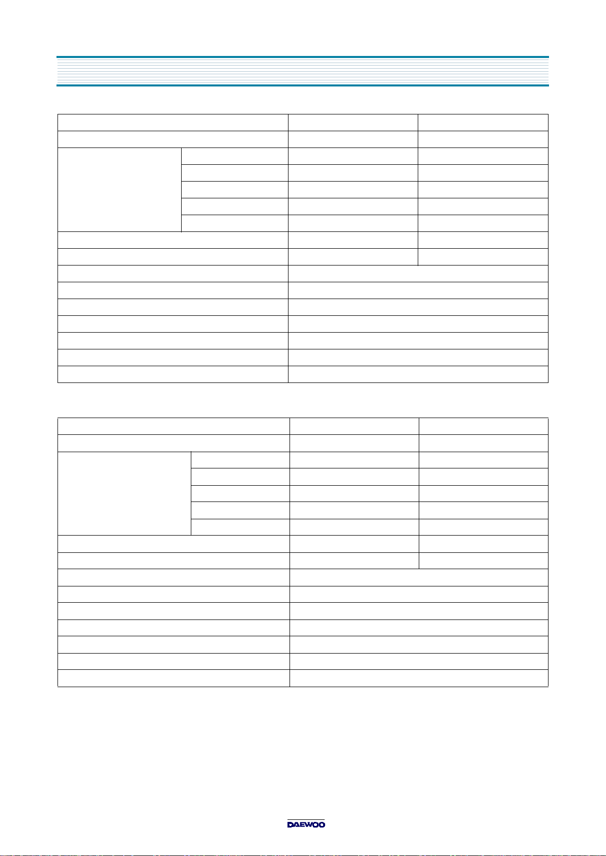
OUT S ID E D IM EN S ION S (W X H X D ) 52 6 x 3 4 5 x 4 1 2 mm ( 20 .7 x 13 .6 x 1 6 .2 in.)
CAVITY DIMENSIONS (W X H X D) 335 x 250 x 339 mm (13.2 x 9.8 x 13.3 in.)
NET WEIGH T AP PR O X. 19 .5 K g (4 3 lb s.)
TIMER 60 minutes
FUNCTION SELECTIONS MICROWAVE/GRILL/CONVECTION/COMBI
POWER SELECTIONS 10 LEVELS
CAV ITY VO L U ME 1.0 C u .F t.
CON VE C T ION 1550W 1550W
AUTO C OO K 1850W 1850W
COM BINATION 2600W (Simultaneous) 1550W (Sequential)
MOD EL KOC980T10S KOC980T20S
POW ER S UPP LY 230V~50Hz 230V~50Hz
MICROW AVE 1450W 1450W
GRILL 1200W 1200W
POWER CONSUMPTION
MICROW AVE ENERG Y OU TPU T 1000W(IEC705) 1000W(IEC705)
MICROW AVE FREQ UEN CY 2450MHz 2450MHz
OUTSIDE D IMENSION S (W X H X D) 526 x 345 x 482 mm (20.7 x 13.6 x 19.0 in.)
CAVITY DIMENSIONS (W X H X D) 335 x 250 x 339 mm (13.2 x 9.8 x 13.3 in.)
NET W EIGHT APPROX . 21 Kg (46.3 lbs.)
TIMER 60 minutes
FUNCTION SELECTIONS MICROWAVE/GRILL/C ONVECTION/COMBI
POWER SELECTIONS 10 LEVELS
CAVITY VOLUM E 1.0 Cu.Ft.
SPECIFICATIONS ARE SUBJECT TO CHANGE WITHOUT NOTICE.
CONV ECTION 1550W 1550W
AUTO CO O K 1850W 1850W
COM BINATION 2600W (Simultaneous) 1550W (Sequential)
Page 5
EXTER N AL VIEW
1. OUTER DIMENSION
KOC-970T
KOC980T
Fig.1 Front view
Fig.2 Side view
Fig.1 Front view Fig.2 Side view
Page 6
2. FEATURE DIAGRAM
KOC-970T
EXTERNAL VIEW
1.
Door seal
2.
Door hook
the oven is operating, the magnetron will immediately stop operating.
3.
Door viewing screen
4.
Top heater
5.
Oven lamp
6.
Safety interlock system
7.
Control panel
8.
Turntable tray
It can also be used as a cooking utensil.
9.
Oven front plate
10.
Rotating base
It should only be removed for cleaning.
11.
Under heater
- Door seal maintains the microwave energy within the oven cavity and prevents microwave leakage.
- When the door is closed, it will automatically shut. If the door is opened while
- Allows viewing of food. The screen is designed so that light can pass through, but not the microwave.
- Turns on when convection, grill and combi cooking is selected.
- Automatically turns on during oven operating.
- Rotates during cooking and ensure even distribution of Microwaves.
- This fits over the shaft in the center of the ovens cavity floor. This is to remain in the oven for all cooking.
Page 7
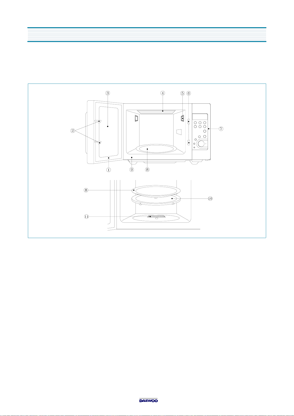
EXTERNAL VIEW
KOC980T
1.
Door seal
2.
Door hook
- Door seal maintains the microwave energy within the oven cavity and prevents microwave leakage.
- When the door is closed, it will automatically shut. If the door is opened while the oven is operating,
the magnetron will immediately stop operating.
3.
Door viewing screen
4.
Top heater
5.
Oven lamp
6.
Safety interlock system
7.
Control panel
8.
Turntable tray
- Turns on when convection, grill and combi cooking is selected.
- Automatically turns on during oven operating.
- Allows viewing of food. The screen is designed so that light can pass through, but not the microwave.
- Rotates during cooking and ensure even distribution of Microwaves.
It can also be used as a cooking utensil.
9.
Oven front plate
10.
Rotating base
- This fits over the shaft in the center of the ovens cavity floor. This is to remain in the oven for all cooking.
It should only be removed for cleaning.
11.
Under heater
12.
Metal rack
Page 8

INST ALLA TION
1. Steady, flat location
This microwave oven should be set on a steady, flat surface.
This microwave oven is designed for counter top use only.
2. Leave space behind and side
All air vents should be kept a clearance. If all vents are covered during operation, the oven may overheat and,
eventually, cause failure.
3. Away from radio and TV sets
Poor television reception and radio interference may result if the oven is located close to a TV, radio, antenna or
feeder and so on. Position the oven as far from them as possible.
4. Away from heating appliances and water taps
Keep the oven away from hot air, steam or splash when choosing a place to position it, or the insulation might be
adversely affected and breakdowns occur.
5. Power supply
Check your local power source. This microwave oven requires a current of approximately 13amperes, 230 Volts, 50 Hz.
•
Power supply cord is about 1.2 meters long.
The voltage used must be the same as specified on this oven. Using a higher voltage may result in a fire or other
•
accident causing oven damage. Using low voltage will cause slow cooking. We are not responsible for damage
resulting from use of this oven with a voltage of ampere fuse other than those specified.
This appliance is supplied with cable of special type, which, if damaged, must be repaired with cable of same type.
•
Such a cable can be purchased from DAEWOO and must be installed by a Qualified Person.
6. Examine the oven after unpacking for any damage such as:
A misaligned door, broken door or a dent in cavity.
If any of the above are visible, DO NOT INSTALL, and notify dealer immediately.
7. Do not operate the oven if it is colder than room temperature.
(This may occur during delivery in cold weather.) Allow the oven to become room temperature before operating.
EARTHING INSTRUCTIONS
This appliance must be earthed. In the event of an electrical short circuit, earthing reduces the risk of the electric shock by providing an escape wire for the electric current. This a ppliance is equipped with a cord having a earth ing wire with a earthing plug.
The plug must be plugged into an outlet that is properly installed and earthed.
WARNING
Improper use of the earthing plug can result in a risk of electric shock.
Consult a qualified electrician or servicem an if the earthing instructions are not com pletely understood, or if doubt
exists as to whether the appliance is properly earthed, and either:
If it is necessary to use an extension cord, use only a 3-wire extension cord that has a 3-blade earthing plug,
and a 3-slot receptacle that will accept the plug on the appliance.
The marked rating of the extension cord should be equal to or greater than the electrical rating of the appliance,
or Do not use an extension cord.
Page 9
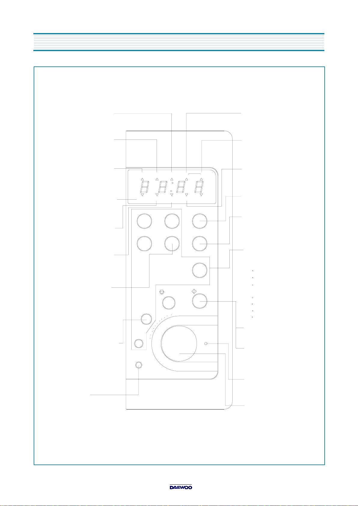
CONTROL PANE L
When blinking, the oven is
operating in "C O MBI"
cooking mode.
When blinking, the oven is
operating in "GRILL"
cooking mode.
When blinking, the oven is
operating in "MICROWA VE"
cooking mode.
When blinking, the oven is
operating in "AUTO COO K"
cooking m ode.
When blinking, the oven is
operating in "PIE"
cooking m ode.
When blinking, the oven is
operating in "CONVECTION"
cooking m ode.
Temperature Button-
Us e d to se t d es ire d
tempe ra ture . If th is b u tto n
is pre s se d fo r m o re th a n
1.3 sec, number is
scrolled up automatically.
Microwave Power Level-
U se d to se lec t th e va ria b le
m icro wave p o w e r le v el. If
this button is pressed for
more than 1.3 sec, number
is sc ro lled up a u to matica lly.
Clock Bu tton-
Us e d to se t tim e
M/W GRILL COMBI
PIE
AUTO
COOK
Grill
Pie
M/W
Defrost
-
Clock
TEMP
COOK
Combi
Temp
Au to Cook
1.Roast Beef
2.Roast Pork
3.Roast Chicken
4.Fish F illets
5.Vegetable
STOP/
CLEAR
+
TIME/WEIGHT
DEFROST
WEIG H T - TIME
KG
+1min
+10sec
Speedy
START
When blinking, the oven is
operating in "WEIGHT
DEFRO ST" cooking mode.
When blinking, the oven is
operating in "TIME
DEFRO ST" cooking mode.
When blinking, the oven is
op e ratin g in weg h t inp u t
mode.
C o o k ing time is in c r e a s e d
by 1 m inute.
C o o k ing time is in c r e a s e d
by 10 seconds.
Function Button-
Used to select desired
cooking function.
M/W : MICROWAVE
Grill
De fro s t : T IM E o r WE IGH T
DEFROST
Temp : CONVECTION
Combi : COMBINATION
Pie
Auto Cook
S tart B u tto n-
Us e d to sta rt the s e lec te d
cooking cycle.
Speedy Cook B utton-
Us e d to p ro g ra m q u ic kly
co ok in g time in 3 0 s e c
increments.
Guide Lam p-
W h e n blin kin g , it info rm s y o u to
be ready to operate dial kn ob.
Dial Knob-
Us e d to se t the c o o kin g tim e ,
time of day and w eight input.
Page 10
D ISASSEM BLY AND ASSEMBLY
Cautions to be observed when trouble shooting.
Unlike many other appliances, the microwave oven is high-voltage, high-current equipment.
It is completely safety during normal operation.
However, carelessness in servicing the oven can result in an electric shock or possible danger from a short circuit.
You are asked to observe the following precautions carefully.
1. Always remove the power plug from the outlet before servicing.
2. Use an insulated screwdriver and ware rubber gloves when servicing the high voltage side.
3. Discharge the high voltage capacitor before touching any oven components or wiring.
(1) Check the earthed.
Do not operate on a two-wire extension cord.
The microwave oven is designed to be used with earthed.
It is imperative, therefore, to makes sure it is earthed properly before
beginning repair work.
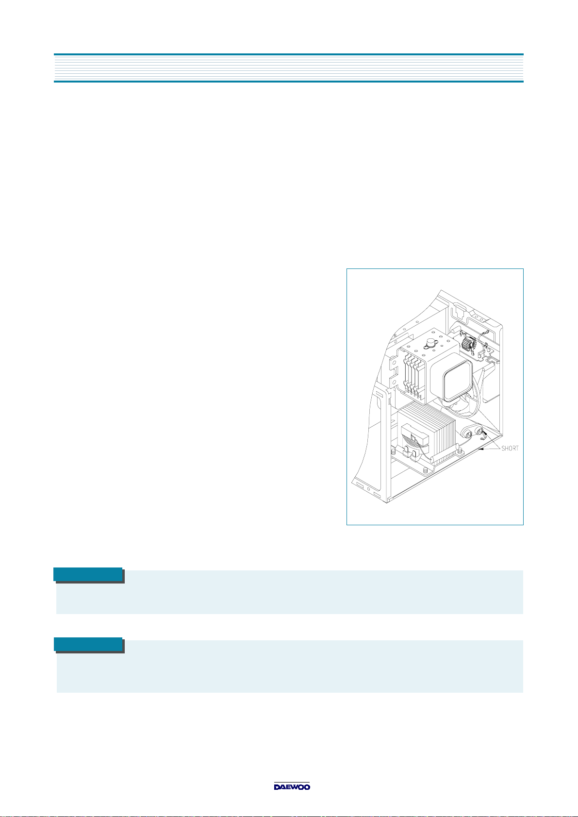
(2) Warning about the electric charge in the high voltage capacitor.
For about 30 seconds after the operation stopped and electric charge
remains in the high voltage capacitor.
When replacing or checking parts, short between oven chassis and
the negative high terminal of the high voltage capacitor,
by using a properly insulated screwdriver to discharge.
4. When the 15A fuse is blown out due to the operation of the monitor switch;
replace primary interlock switch, secondary interlock
switch and interlock monitor switch.
5. After repair or replacement of parts, make sure that the screws are
properly tightened, and all electrical connections are tightened.
6. Do not operate without cabinet.
CAUTION
Service personnel should remove their w atches whenever working close to or replacing the magnetron.
WARNING
When servicing the appliance, need a care of touching or replacing high potential parts because of electrical shock or
exposing m icrowave. These parts are as follows - HV Transform er, Magnetron, HV Capacitor, HV D iode.
Page 11
DISASSEMBLY AND ASSEM B LY
1. To remove cabinet
(1) Remove four screws on cabinet back.
(2) Push the cabinet backward.
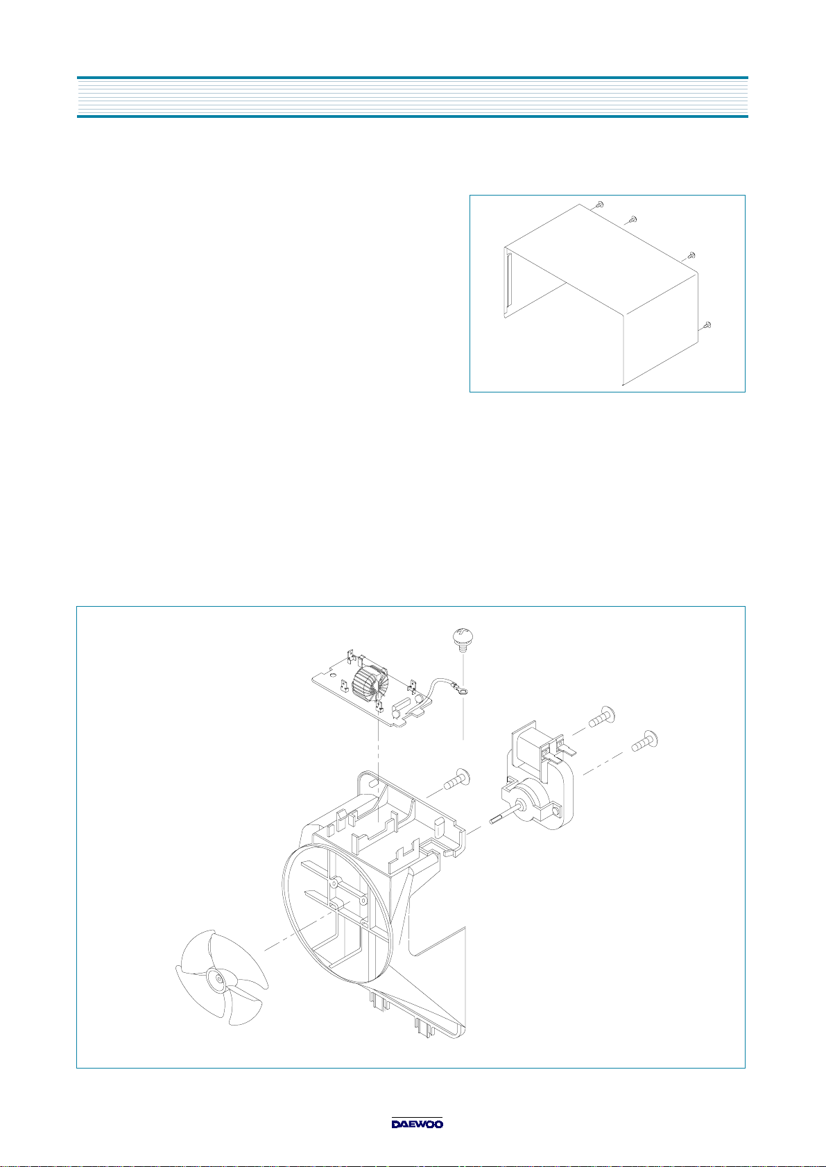
2. To remove guide wind assembly
(1) Remove two screws for earthing and for fixing to rear-plate.
(2) Remove the noise filter from the guide wind.
(3) Pull the fan from the motor shaft.
(4) Remove two screws which secure the motor shaded pole.
(5) Remove the motor shaded pole.
(6) Reverse the above steps for reassembly.
Page 12
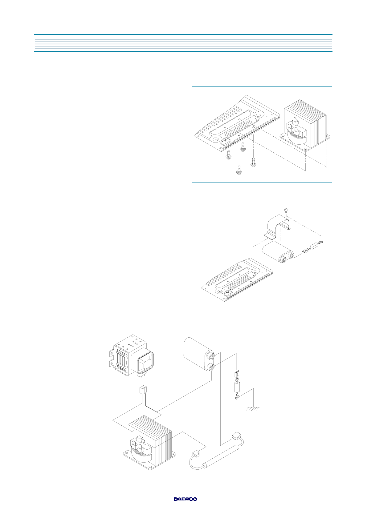
3. To remove H.V.transformer
(1) Remove four screws which secure
the H.V.transformer to the base plate.
(2) Remove the H.V.transformer.
(3) Reverse the above steps for reassembly.
4. To remove hig h vol tag e cap aci tor
(1) Remove a screw which secure the grounding ring
terminal of the H.V. diode and the capacitor holder.
(2) Remove the H.V. diode from the capacitor holder.
(3) Reverse the above steps for reassembly.
DISASSEMBLY AND ASSEMBLY
High voltage circuit wiring
Page 13
DISASSEMBLY AND ASSEM B LY
5. To remove magnetron
(1) Remove three screws which secure the magnetron.
(2) Remove the magnetron.
(3) Reverse the above steps for reassembly.
CAUTION
Never install the magnetron without the m etallic gasket plate which is packed with each m agnetron to prevent
microwave leakage. Whenever repair work is carried out on magnetron, check the m icrowave leakage.
2
It shall not exceed 4mW /cm
for a fully assembled oven with door normally closed.
Page 14
6. To remove control panel assembly
(1) Remove a screw which secure the control panel assembly to
the oven front plate. At the same time, draw forward the control panel
assembly from the oven front plate.
(2) Remove the dial knob.
(3) Remove nine screws which secure the main and
sub PCB assembly to control panel.
(4) Remove buttons.
(5) Remove the window display and decorator panel.
DISASSEMBLY AND ASSEMBLY
REF NO. PART CODE PART NAME DESCRIPTION QTY REMARK
B01 3511602400 DECO RATOR C-PANEL ABS 1
B02 3515501200 WINDO W D ISPLAY PMM A IF-850 1 SMO G
B03 3516715110 CONTROL-PANEL ABS 1
B04 3516906000 BUTTON FUN CTION ABS 1
B05 3516905900 BUTTON FUN CTION ABS 1 KO R-816
B06 3516905800 BUTTON S TART ABS 1 KO R-816
B07 3516906100 BUTTON FUN CTION ABS 1
B08 PKBPMSQ200 PCB SUB AS KOC-970T/980T 1
PKMPMSQ200 PCB MAIN AS KOC-970T1S 1
B09
B10 7121300811
B11 3513403810
PKMPMSQ230 PCB MAIN AS KOC-970T2S 1
PKMPMSYA00 PCB MAIN AS KOC980T10S 1
PKMPMSYA00 PCB MAIN AS KOC980T20S 1
SCREW TAPPING T2S PAN 3x8 MFZN
KNOB VOLUME ABS
9
1 KOR-816
Page 15
DISASSEMBLY AND ASSEM B LY
7. To remove door assembly
(1) Remove two screws which secure the stopper hinge top.
(2) Remove the door assembly from top plate of cavity.
(3) Reverse the above steps for reassembly.
NOTE
After replacing the door assem bly, perform a check of
correct alignm ent with the hinge and cavity front plate.
8. To remove door parts
(1) Remove the gasket door. (4) Remove the hook and spring.
(2) Remove two screws. (5) Remove the supporter and barrier-screen *o.
(3) Remove the door seal assy. (6) Remove the handle from the frame door.
REF NO. PART CODE PART NAME DESCRIPTION QTY REMARK
A01 3512203320 FRAM E DO OR ABS 1
A02 3512601400 HAND LE DO OR AB S 1
A03 3517004020 BARRIER-SCREEN *O TEMPER ED G LASS T3.2 1
A04 3515304700 SUPPO RTER BAR R-S *O N YLO N 66 1
A05 3511708400 DOOR SEA L AS KOC-971C 1
A06 3513101100 HOOK POM 1
A07 3515101300 SPRING HO O K PW1 1
A08 3515203600 STOPPER HINGE *T AS KOC -970T1S 1
A09 7121400811 SCREW TAPPING T2S PAN 4x8 MFZN 2
A10 3512300800 GASKE T DO OR PB T 1
Page 16

DISASSEMBLY AND ASSEMBLY
9. Method to reduce the gap between the door seal and the oven front surface.
(1) To reduce gap located on part ‘A’
Loosen two screws on stopper hinge top, and then push
•
the door to contact the door seal to oven front surface.
Tighten two screws.
•
(2) To reduce gap located on part ‘B’
Loosen two screws on stopper hinge under, and then push
•
the door to contact the door seal to oven front surface.
Tighten two screws.
•
(3) To reduce gap located on part ‘C’
Loosen a screw on interlock switch assembly
•
located bottom of oven body.
Draw the interlock switch assembly inward as possible to engage with hook on the door bottom.
•
Tighten a screw.
•
(4) To reduce gap located on part ‘D’
Loosen a screw on interlock switch assembly located top of oven body.
•
Following steps are same as step (3).
•
NOTE
Small gap may be acceptable if the microwave leakage does not exceed 1mW /cm
2
NOTE
The door on a microwave oven is designed to act as an electronic seal preventing the leakage of microwave energy
from the oven cavity during the cook cycle. This function does not require that the door be air-tight, moisture (condensation) Tight or light-tight. Therefore, the occasional appearance of moisture, light or the sensing of gentle warm air
movem ent around the oven door is not abnormal and do not of them selves, indicate a leakage of microw ave energy
from the oven cavity. If such were the case, your oven could not be equipped with a bent, the very purpose of which
is to exhaust the vapor-laden air from the oven cavity.
Page 17

DISASSEMBLY AND ASSEM B LY
10. To remove motor syncro and under heater
(1) Cut the syncro motor cover parts from the base plate.
(2) Remove two screws which secure the motor syncro and supporter to bracket syncro motor.
(3) Remove two screws and under heater assembly in cavity
11. To remove grill heater assembly
(1)Remove two screws which secure the cover insulator *t to top plate.
(2) Remove the harness between heaters.
(3) Remove two screws for removing heater brackets.
(4) Remove heaters.
(5) Reverse the above steps for reassembly.
Page 18

DISASSEMBLY AND ASSEMBLY
12. To remove convection part assembly (KOC980T only)
(1) Remove cover *b and cover insulator *b protecting convection part assembly. - release two lances of cover insulator *b.
(2) Remove four screws which secure the convection part assembly to the cavity rear plate.
(3) Remove a nut holding the convection fan and the pipe.
(4) Remove two screws which secure the bracket motor to cover insulator.
(5) Remove the cooling fan.
(6) Remove two screws which secure the motor shaded pole to the bracket motor.
(7) Reverse the above steps for reassembly.
Page 19

INTER LOC K ME CHANISM AND ADJUSTMENT
The door lock mechanism is a device which has been specially designed to completely eliminate microwave radiation when the
door is opened during operation, and thus to perfectly prevent the danger resulting from the leakage of microwave.
1. Primary interlock switch
When the door is closed, the hook locks the oven door. If the door is not closed properly, the oven will not operate.
When the door is closed, the hook pushes the button of the microswitch.
Then the button of the primary interlock switch bring it under “ON” condition.
2. Secondary interlock switch, door open monitor switch and interlock monitor switch
When the door is closed, the hook pushes the latch lever downward.
The latch lever presses the button of the interlock monitor switch to bring it under “OFF” condition and
presses the button of the secondary interlock switch and door open monitor switch to bring it under “ON” condition.
ADJUSTMENT
Interlock monitor switch
When the door is closed, the interlock monitor switch should be opened before other switches are closed.
When the door is opened, the interlock monitor switch should be closed after other switches are opened.
3. Adjustment steps
(1) Loosen two mounting screws.
(2) Adjust interlock switch assembly position.
(3) Make sure that latch lever moves smoothly after adjustment is completed.
(4) Tighten completely two mounting screws.
NOTE
Microwave emission test should be performed after adjusting interlock mechanism.
If the microwave emission exceed 4mW/cm
2
, readjust interlock mechanism.
Page 20

TROUBLE SHOOTING GUIDE
CONDITION
Following the procedures below to check if the oven is defective or not.
1. Check grounding before checking trouble.
2. Be careful of the high voltage circuit.
3. Discharge the high voltage capacitor.
4. When checking the continuity of the switches, fuse or high voltage transformer, disconnect one lead wire from these parts
and then check continuity with the AC plug removed. To do otherwise may result in a false reading or damage to your meter.
NOTE
When electric parts are checked, be sure the power cord is not inserted the wall outlet.
Check wire harness, wiring, and connected of the terminals and power cord before check parts listed below.
(TROUBLE 1)
Fuse blows.
Oven does not operate at all; any inputs can not be accepted.
CHECK RESULT CAUSE REMEDY
(COM NC)
Check continuity of
interlock m o nitor switch
with door closed
(COM NC)
Check continuity of both
prim ary and secondary
interlock sw itch with
door closed
Check continuity of
primary interlock switch
contact with door
partially open until
interlock m o nitor switch
contact close
(COM NC close)
Continuity
(COM NC)
No C ontinuity
No
Continuity
Continuity
Continuity
Malfunction
of interlock
monitor
switch
Malfunction
of interlock
switch
Shorted
contacts of
prim ary
interlock
switch
Replace
NOTE 1
Replace
NOTE 1
Replace
NOTE 1
Check continuity of
prim ary winding of low
voltage transformer
Disconnect high voltage
fuse and operate the unit
0 infinite
or
Ω
Approx.
150~210
(normal)
Fuse again
blows
Defective low
voltage
transformer
Defective
high voltage
transformer
Replace
Replace
Page 21

TROUBLE SHOOTING GUIDE
CONDITION
CONDITION
CHECK RESULT CAUSE REMEDY
Outlet has
proper voltage
Fuse does not
blow.
Check continuity of
magn etron
Check continuity of noise
filter board
Check continuity of
power supply cord
No
Continuity
No
Continuity
No
Continuity
Normal
Defective
magn etron
Defective
noise filter board
Open pow er
supply cord
Defective
touch control
circuit
NOTE
All these switches must be replaced at the same time, please refer to (7.Interlock Mechanism and Adjust)
for adjustment instructions.
(TROUBLE 2)
Grill heater (top heater) is not heated; Food will not become hot.
Replace
Replace
Adjust
Adjust
Grill heater is
not heated.
CHECK RESULT CAUSE REMEDY
Check continuity of
primary interlock switch
Check continuity of
secondary interlock switch
Check continuity of
heater
Che ck D .C. voltage
being supplied to
RELAY (RY2) coil
No
Continuity
No
Continuity
No
Continuity
0 V
Approx
12 VDC
Malfunction
of primary
interlock sw itch
Malfunction
of secondary
interlock sw itch
Defective
heater
Defective
touch control
circuit
Faulty
contacts of
RELAY
(RY2) or open
relay coil
Adjust or
Replace
Adjust or
Replace
Replace
Replace
Replace
Page 22

TR OUBLE SH OOTING GUIDE
CONDITION
Continuity
0 or
No
Continuity
No
Continuity
0 V
Approx
13 VDC
Defective
high voltage
Defective
high voltage
Defective
magnetron
Defective
magnetron
Defective
high voltage
Defective
high voltage
Defective
Faulty
contacts of
Replace
Replace
Replace
Replace
Replace
Replace
Replace
Replace
(TROUBLE 3)
No microwave
oscillation
No microwave oscillation even though fan motor rotates.
CHECK RESULT
Check continuity of high
voltage fuse
Replace high voltage fuse
Check continuity of high
voltage capacitor
term in a ls with w ire s
remov ed
Check continuity of high
voltage rectifier in
forw ard and backward
direction with D C
megg er
Connect megger leads to
magn etron terminal and
magn etron body
No
Continuity
Continuity
Continuity in
backward
direction
CAUSE
transformer
rectifier
REMEDY
Check resistance of
prim ary and secondary
coil of high voltage
transformer
Check continuity of
magn etron w ith wires
remov ed
Check continuity of
filament terminal of high
voltage transformer
Che ck D .C. voltage
being supplied to
RELAY (RY3) coil
Ω
transformer
transformer
touch control
circuit
RELAY
(RY3) or open
relay coil
Page 23

TROUBLE SHOOTING GUIDE
CONDITION
Adjust or
Adjust or
Replace
Replace
Malfunction
0 V
Approx.
Malfunction
Defective
Faulty
contacts of
CONDITION
Adjust or
Adjust or
Replace
Replace
Malfunction
0 V
Approx.
Malfunction
Defective
Faulty
contacts of
Replace
(TROUBLE 4)
Turn table
motor and
oven lamp do
not turn on
Display shows all figures selected, but oven does not start cooking,
even though desired program and time are set and start pad is tapped.
CHECK RESULT CAUSE REMEDY
Check continuity of
primary interlock switch
Check continuity of
secondary interlock and
D.O.M . switch
Che ck D .C. voltage
being supplied to
RELAY (RY4) coil
No
Continuity
No
Continuity
13 VDC
of primary
interlock
switch
of secondary
interlock and
D.O.M . switch
touch control
circuit
RELAY
(RY4) or open
relay coil
replace
replace
(TROUBLE 5)
1) Under heater
is not heated.
2) Convection
fan and motor
do e s n o t ro t a te .
1) Under heater is not heated; Food will not become hot.
2) Convection motor does not rotate.
CHECK RESULT CAUSE REMEDY
Check continuity of
primary interlock switch
Check continuity of
secondary interlock sw itch
Check continuity of
heater (motor)
Che ck D .C. voltage
being supplied to
RELAY (RY6) coil
No
Continuity
No
Continuity
No
Continuity
of primary
interlock
switch
of secondary
interlock switch
Defective
heater(motor)
touch control
circuit
replace
replace
13 VDC
RELAY
(RY6) or open
relay coil
Page 24

TR OUBLE SH OOTING GUIDE
CONDITION
(TROUBLE 6)
The following visual conditions indicate a probable defective touch control circuit or button P.C.B. assembly.
1. Incomplete segments
(1) Segments missing
(2) Partial segments missing
(3) Digit flickering other than normal fluorescent slight flickering
(4) 0 does not display when power is on.
2. A distinct change in the brightness of one or
more numbers exists in the display.
3. One or more digits in the display are not on
when they should be.
4. Display indicates a number different from one touched.
(for example, even if one touched 5, 3 appears in the display.
5. Specific numbers (for example, 2 or 3) do not display
when the button is touched.
6. Display does not count down or up with time cooking or
clock operation.
7. Oven is programable and cooks normally but no display shows.
8. Display obviously jumps in time while counting down.
9. Display counts down noticeably too fast while cooking.
10. Display does not show the time of day when clear button is touched.
11. Oven lamp and turntable motor do not stop although cooking is finished.
Check if the RELAY (RY3) contacts close and if they are close, replace touch control circuit.
CHECK RESULT CAUSE REMEDY
Display does
not show
programm ing
at all, even if
keyboard is
touched.
Check each button for
continuity of the button
keyboard for the
following keyboard
check procedure
Normal
Normal
Malfunction
of touch
control circuit
of control box
sub-assembly
Malfunction
of botton
keyboard
NOTE
Before following the particular steps listed above in the trouble shooting guide for the button keyboard’s failure,
please check for the continuity of each wire-harness between the button keyboard and P.C.B. assembly.
Replace
control box
sub-assembly
Replace
the button
keyboard
Page 25

TROUBLE SHOOTING GUIDE
BUTTON KEYBOARD CHECK PROCEDURE
1. Type of button names
( key metrix and circuit diagram )
The tact switch keyboard consists of 10 keys which configurations are described above.
2. Key check procedure
To determine if the tact switch keyboard is defective or not, check the continuity of each
button(key) contacts with a multimeter.
(1) AUTO COOK button : between 4 and 10
(2) DEFROST button : between 4 and 14
(3) TEMP button : between 8 and 12
(4) MICROWAVE button : between 6 and 14
(5) COMBI button : between 6 and 12
(6) GRILL button : between 2 and 10
(7) +10 SEC button : between 8 and 10
(8) +1 MIN button : between 6 and 10
(9) STOP/CLEAR button : between 2 and 12
(10) START button : between 4 and 12
(11) CLOCK button : between 8 and 14
(12) PIE button : between 2 and 14
Page 26

ME ASUR E M E NT AND TEST
1. MEASUREMENT OF THE MICROWAVE POWER OUTPUT
Microwave output power can be checked by indirectly measuring the temperature rise of a certain
amount of water exposed to the microwave as directed below.
PROCEDURE
1. Microwave power output measurement is made wit the microwave oven supplied at rated voltage and operated at its
maximum microwave power setting with a load of 1000 ± 5cc of potable water.
2. The water is contained in a cylindrical borosilicate glass vessel having a maximum material thickness of 3 mm and
an outside diameter of approximately 190 mm.
3. The oven and the empty vessel are at ambient temperature prior to the start of the test.
The initial temperature of the water is 10 ± 2 °C (50 ± 3.6 °F).
It is measured immediately before the water is added to the vessel.
After addition of the water to the vessel, the load is immediately placed on the center of the shelf,
which is in the lowest normal position.
4. Microwave power is switched on.
5. Heating time should be exactly A seconds.
Heating time is measured while the microwave generator is
operating at full power.
The filament heat-up time for magnetron is not included.
6. The initial and final temperature of water is selected so that the maximum
difference between the ambient and final water temperature is 5K.
7. The microwave power output P in watts is calculated from the following formula:
P = 4187
DT is difference between initial and ending temperature.
•
t is the heating time.
•
The power measured should be B (refer to 2. Specifications)W ± 10.0 %.
T/t
CAUTION
1. Water load should be measured exactly to 1 liters.
2. Input power voltage should be exactly specified voltage(Refer to 2. SPECIFICATIONS).
3. Ambient temperature should be 20 ± 2 °C (68 ± 3.6°F)
Heating time for power output:
(second) 70 64 60 56 52 49 47 44 42 40 38
A
(W) 600 650 700 750 800 850 900 9 50 1000 1050 1100
B
Page 27

MEASURE M ENT AND TEST
2. ELECTRICAL CONTINUITY CHECK OF INTERLOCK SWITCH
NOTE
Remove the power plug from the wall receptacle before testing.
PROCEDURE
1. Primary interlock switch
(1) Disconnect two connectors from primary interlock switch.
(2) Connect the ohm-meter leads between the terminals of the primary interlock switch.
2. Read the value of resistance between the terminals of the switch, when the door is opened, and when the door is closed.
3. Secondary interlock switch
(1) Disconnect two connectors from secondary interlock switch.
(2) Connect the ohm-meter leads between the terminals of the secondary interlock switch.
(3) Read the value of resistance between the terminals of the switch, when the door is opened,
and when the door is closed.
3. Monitor interlock switch
(1) Disconnect the lead wire connecting the primary interlock switch and interlock monitor switch from
primary interlock switch terminal.
(2) Connect the ohm-meter leads between the lead wire connector disconnected as item1 and
the power supply neutral plug pin.
(3) Read the value of resistance between the lead wire connector and the power supply neutral plug pin,
when the oven door is opened, and when the oven door is closed.
JUDGEMENT
The value of resistance should be applied to the value specified below.
•
Switch Door Open Door Close
Primary interlock sw itch
Secondary interlock switch
Interlock monitor circuit 0
When value obtained is not acceptable, the switch should be replaced or adjusted again.
•
0
0
Page 28

MEASUREMENT AND TEST
3. MICROWAVE RADIATION TEST
WARNING
Make sure to check the m icrowave leakage before and after repair of adjustment.
Always start measuring of an unknown field to assure safety for operating personnel from m icrowave energy.
Do not place your hands into any suspected m icrowave radiation field unless the safe density level is known.
Care should be taken not to place the eyes in direct line with the source of m icrowave energy.
Slowly approach the unit under test until the radiom eter reads an appreciable microwave leakage from the unit
under the test.
PROCEDURE
1. Prepare Microwave Energy Survey Meter, 600cc glass beaker,
and glass thermometer 100°C (212°F ).
2. Pour 275cc ±15cc of tap water initially at 20 ± 5 °C (68 ± 9°F)
in the 600 cc glass beaker with an inside diameter of approx.
95 mm(3.5 in.).
3. Place it at the center of the tray and set it in a cavity.
4. Close the door and operate the oven.
5. Measure the leakage by using Microwave Energy Survey Meter
with dual ranges, set to 2450MHz.
Measured radiation leakage must not exceed the value prescribed below.
•
Leakage for a fully assembled oven with door normally
closed must be less than 4mW/cm2.
When measuring the leakage, always use the 5 cm (2 in.)
•
space cone with probe.
Hold the probe perpendicular to the cabinet and door.
Place the space cone of the probe on the door, cabinet, door seem,
door viewing screen, the exhaust air vents and the suction air vents.
Measuring should be in a counter-clockwise direction at a rate of 1 in./sec.
•
If the leakage of the cabinet door seem is unknown, move the probe more slowly.
When measuring near a corner of the door, keep the probe perpendicular to
•
the areas making sure the probe end at the base of the cone does not get closer than 2 in. from any metal.
If it does not, erroneous reading may result.
Page 29

MEASURE M ENT AND TEST
4. COMPONENT TEST PROCEDURE
High voltage is present at the high voltage terminal of the high voltage transformer during any cooking cycle.
It is neither necessary nor advisable to attempt measurement of the high voltage.
Before touching any oven components or wiring, always unplug the oven from its power source and discharge the capacitor.
1. High voltage transformer
(1) Remove connections from the transformer terminals
and check continuity.
(2) Normal readings should be as follows :
Secondary winding ... Approx. 100
Filament winding ... Approx. 0.1
Primary winding ... Approx. 1.5
2. High voltage capacitor
(1) Check continuity of capacitor with meter on the highest OHM scale.
(2) A normal capacitor will show continuity for a short time,
and then indicate 9M
once the capacitor is charged.
(3) A shorted capacitor will show continuous continuity.
(4) An open capacitor will show constant 9M
(5) Resistance between each terminal and chassis should be infinite.
10%
3. High voltage diode
(1) Isolate the diode from the circuit by disconnecting the leads.
(2) With the ohmmeter set on the highest resistance scale measure the resistance across the diode terminals.
Reverse the meter leads and again observe the resistance reading.
Meter with 6V, 9V or higher voltage batteries should be used to check the front-back resistance of the diode,
otherwise an infinite resistance may be read in both directions.
A normal diode's resistance will be infinite in one direction and several hundred k
in the other direction.
4. Magnetron
For complete magnetron diagnosis, refer to "Measurement of the Microwave Output
Power." Continuity checks can only indicate and open filament or a shorted magnetron.
To diagnose for an open filament or a shorted magnetron,
(1) Isolate magnetron from the circuit by disconnecting the leads.
(2) A continuity check across magnetron filament terminals should indicate 0.1
or less.
(3) A continuity check between each filament terminal and magnetron case should read open.
5. Fuse
If the fuse in the primary and monitor switch circuit is blown when the door is opened, check the primary and monitor switch
before replacing the blown fuse.
In case the fuse is blown by an improper switch operation, replace the defective switch and fuse at the same time.
Replace just the fuse if the switches operate normally.
Page 30

WIRING DIAGR AM
Page 31

SCHEMAT IC DIAGRAM
Page 32

SC H EMATIC DIAGRAM
Page 33

SCHEMATIC DIAGRAM
Page 34

EXPLO DED VIEW S AND PARTS LIST
1. KOC-970T
EXPLODED VIEW
Page 35

EXPLODED VIEWS AND PARTS LIST
PARTS LIST
REF NO. PART CODE PART NAM E DESCR IPTION QTY REM ARK
A00 3511708310 D O O R AS KOC-970T 1
B00
F1 3516107910 CAVITY W ELD AS KOC-970T 1
F2 3516503300 REAR-PLATE *O SBHG-1 TO.6 1
F3 3514800800 SENSOR TEM PER ATURE PTM-K312-D4 1
F4 7113400814 SC REW TAPPING T1 BIN 4*8 MFNI 1
F5 3511403800 CO VE R WAVE GU IDE MICA TO.5 1
F6 7113400814 SC REW TAPPING T1 BIN 4*8 MFNI 1
F7 3514400600 PIPE BRASS C3604BD 1
F8 3517401300 COUP LER CERAM IC 1
F9 3966510200 MOTOR SYNC RO 230V 25W GM -16-24FD24 1
F10 7121400811 SCREW TAPPING T2S PAN 4*8 MFZN 2
F11 3510604000 BRACKET M OTO R SY NC RO SECC TO.8 1
F12 7113400814 SCREW TAPPING T1 BIN 4*8 MFNI 1
F13 3512802100 H EATER *U AS KO C-971COS 1
F14 7113400814 SCREW TAPPING T1 BIN 4*8 MFNI 2
F15 3510310400 BA SE SBHG-1 T0.8 1
F16 3515202810 STOPPER HINGE *U AS KO C -970T 1
F17 7S422X4081 SCREW SPECIAL TT2 TRS 4*8 SE MFZN 2
F18 3512100900 FOOT PP, DASF-130 4
F19 4416W 67820 CAPACITOR HV
F20 441X304112 HOLDER HV CAPACITOR SECC TO.8 1
F21 7S422X4081 SCREW SPECIAL TT2 TRS 4*8 SE MFZN 1
F22 4416V24000 DIODE H V SANKEN H VR-1X-32B(D5.3) 1
F23 3518112100 TRANS H V DY-90S0-97T1 1
F24 7S427W 40A1 SCREW SPECIAL TT2 HEX FG 4*10 SE MFZN 4
F25 7S312X40A1 SCREW SPECIAL T1 TRS 4*10 SE MFZN 6
F26 3513809100 LOCK POM 1
F27 3513601600 LAMP BL 240V25W T25 C 7A H187 1
F28 5S762S10G 0 SW MICRO SZM -V16-FA-63 2
F29 5S762310G0 SW MICRO SZM-V16-FA-61 2
F30 3513701300 LEVER LO CK POM 1
F31 7S341W 40B1 SCRE W SPE CIAL T2S PAN 4*12 PW SE M FZN 2
F32 7S341W 40B1 SCRE W SPE CIAL T2S PAN 4*12 PW SE M FZN 1
F33 7S422X4081 SCREW SPECIAL TT2 TRS 4*8 SE MFZN 1
F34 3517502700 PROTEC TOR H EATER M ICA MT56 T1.0 2
PKCPS W Q200 CONT RO L-PANEL AS KOC-970T1S 1
PKCPS W Q230 CONT RO L-PANEL AS KOC-970T2S 1
2100VAC, 1.1UF
1
Page 36

EXPLODED VIEWS AND PARTS LIST
REF NO. PART CODE PART NAM E DESCR IPTION QTY REM ARK
F35 3510603610 BR ACKE T HEATER *T SECC T0.6 2
F36 7S312X40A1 SCREW SPECIAL TT2 HEX FG 4*10 MFZN 2
F37 3512803000 HEATER MIRACLON 115V 550W 2
F38 3512765100 HARN ESS H EATER #187 FLAG 65MM 1
F39 3517302500 FOAM CR 10T*180*30 1
F40 3518002400 MAG NET RO N 2M218J(MF)I 1
F41 7S427W 40A1 SCREW SPECIAL TT2 HEX FG 4*10 SE MFZN 3
F42 3511800100 FAN PP GF20 1
F43 3512505200 GUIDE W IND PP 1
F44 3963513000 M O TOR SH ADED PO LE 230V25W OEM -15DW C2-A03 1
F45 7121403011 SC REW TAPPING T2S PAN 4*30 MFZN 2
F46 7S341W 40B1 SCRE W SPE CIAL T2S PAN 4*12 PW SE M FZN 1
F47
F48
F49 7S312X40A1 SCREW SPECIAL T1 TRS 4*10 SE MFZN 1
F50
F51 7S312X40A1 SCREW SPECIAL T1 TRS 4*10 SE MFZN 2
F52 7S427W 40A1 SCREW SPECIAL TT2 HEX FG 4*10 SE MFZN 2
F53 3512505500 GUIDE AIR OU TLET SA 1D-80 TO.5 1
F54 7S312X40A1 SCREW SPECIAL T1 TRS 4*10 SE MFZN 1
F55 3511404800 C OVE R INSULATOR *T SEC C TO.5 1
F56 7S312X40A1 SCREW SPECIAL T1 TRS 4*10 SE MFZN 1
F57 3510801900 CABINET PCM TO .5 1
F58 7S312X40A1 SCREW SPECIAL T1 TRS 4*10 SE MFZN 4
F59 3512513000 GUIDE TRAY AS KOC-971COS 1
F60 3517205200 TRAY METAL SP P TO.6 1
F61 3518700220 FUSE HV 5KV 0.7A THVO 60T 1
3518604600 NOISE-FILTER DW LF -P(KOC-970T1S) 1
3518605500 NOISE-FILTER DW LF -MO7(KOC-970T2S) 1
4417B67600 FU SE 15A 250V(KOC-970T1S) 1
5F1CD1232M FUSE 12A 250V(KOC -970T2S) 1
35113A5Q5J COR D P O WER AS 3*1.5(KOC-970T1S) 1
35113A5QM5 CORD P O W ER AS 3*1.0(KO C -970T2S) 1
Page 37

EXPLODED VIEWS AND PARTS LIST
2. KOC-980T
EXPLODED VIEW
Page 38

EXPLODED VIEWS AND PARTS LIST
PARTS LIST
REF NO. PART CODE PART NAME DESCRIPTION Q’TY REMARK
A00 3511708310 DOO R AS K OC 980T 1
B00
F01 3516107950 CAVITY WELD AS KOC980TI0S 1
F02 3518904400 THE RM O STAT 120/60, #187 1
F03 7121400611 SC RE W TAPPING T2S PAN 4*6 MFZN 1
F04 7112400811 SCREW TAPPING T1 TRS 4X8 M FZN 1
F05 3511403800 CO VER WAVE GUIDE M ICA TO.5 1
F06 7113400814 SCR EW TAPPING T1 BIN 4*8 MFNI 1
F07 3514400600 PIPE BR ASS C 3604BD 1
F08 3517401300 CO UPLER CER AM IC 1
F09 3966510200 MO TO R SY NCR O 230V 25W G M -16-24FD24) 1
F10 7121400811 SC RE W TAPPING T2S PAN 4*8 MFZN 2
F11 3510604000 BRAC KET M O TOR SY NC RO SECC TO.8 1
F12 7113400814 SCR EW TAPPING T1 BIN 4*8 MFNI 1
F13 3512802100 HEATER *U AS KOC -971COS 1
F14 7113400814 SCR EW TAPPING T1 BIN 4*8 MFNI 2
F15 3510310400 BAS E SBH G TO .8 1
F16 3515202800 STOP PER HINGE *U AS K OR -121MOA 1
F17 7S422X4081 SCREW S PECIAL TT2 TR S 4*8 SE MFZ N 2
F18 3512101400 FOO T PP, DASF-130 4
F19 4416W67820 CAPACITOR HV
F20 441X304112 HO LDER HV CAPACITOR SECC TO.8 1
F21 7S422X4081 SCREW S PECIAL TT2 TR S 4*8 SE MFZ N 1
F22 4416V24000 DIODE H V SANKEN H VR -1X-32B(D5.3) 1
F23 3518112100 TR AN S HV DY-N90S0-97T1 1
F24 7S427W40A1 SCR EW SP ECIAL TT2 HE X FG 4*10 SE MFZN 4
F25 7S312X40A1 SCREW SPECIAL T1 TRS 4*10 SE MFZN 5
F26 3513809100 LOC K POM 1
F27 3513601600 LAM P BL 240V 25W T25 C7A H187 1
F28 5S762S10G0 SW MICRO SZM -V16-FA-63 2
F29 5S762310G0 SW MICRO SZM -V16-FA-61 2
F30 3513701300 LEVER LO CK PO M 1
F31 7122401211 SC REW TAPPING T2S TRS 4*12 MFZN 2
F32 7122401211 SC REW TAPPING T2S TRS 4*12 MFZN 1
F33 7S422X4081 SCREW S PECIAL TT2 TR S 4*8 SE MFZ N 1
F34 3517502700 PRO TE CTOR HEATER M ICA MT56 T1.O 2
F35 3510603610 BRAC KET H EATER *T SECC TO.6 2
F36 7S312X40A1 SCREW SPECIAL T1 TRS 4*10 SE MFZN 2
F37 3512803000 HEATER M IRACLO N 115V 550W 2
F38 3512765100 HARN ESS HEATER #187 FLAG 65MM 1
PKCPSWYA00 CONTROL-PANEL AS KO C980T10S(SIM UL.) 1
PKCPSWYA00 CONTROL-PANEL AS KOC980T20S(SEQUENTIAL) 1
2100VAC, 1.1UF
1
Page 39

EXPLODED VIEWS AND PARTS LIST
REF NO. PART CODE PART NAME DESCRIPTION Q’TY REMARK
F39 3517302500 FO AM CR 10T*180*30 1
F40 3518002400 M AG NE TRO N 2M218J(MF)I 1
F41 7S427W40A1 SCREW SPECIAL TT2 HEX FG 4*10 SE MFZN 3
F42 3511800100 FAN PP GF20 1
F43 3512505200 G UIDE W IND PP 1
F44 3963513000 M O TOR S HA DED POLE
F45 7112403011 S CR EW TAPPING T2S PAN 4*30 MFZN 2
F46 7122401211 S CR EW TAPPING T2S TRS 4*12 MFZN 1
F47
F48
F49 7112401011 S CR EW TAPPING T1 TRS 4*10 MFZN 1
F50
F51 7112401011 S CR EW TAPPING T1 TRS 4*10 MFZN 2
F52 7S427W40A1 SCREW SPECIAL TT2 HEX FG 4*10 SE MFZN 2
F53 3512505500 G UIDE AIR OU TLET SA1D-80 TO.5 1
F54 7112401011 S CR EW TAPPING T1 TRS 4*10 MFZN 1
F55 3511404800 C O VER INSULATOR *T SECC TO .5 1
F56 7112401011 S CR EW TAPPING T1 TRS 4*10 MFZN 1
F57 3510801000 CA BINET PCM TO.5 1
F58 7112401011 S CR EW TAPPING T1 TRS 4*10 MFZN 4
F59 3512513000 G UIDE TR AY AS K OC-971CO S 1
F60 3517205200 TR AY METAL SPP TO.6 1
F61 3514800800 SE NSO R TEM PERATUR E PTM-K312-D4 1
F62 7113400814 S CR EW TAPPING T1 BIN 4*8 MFNI 1
F63 3518700220 FU SE H V 5KV 0.7A 1
F64 3511401300 C O VER INSULATOR *B SBHG -1 0.6T 1
F65 3510601500 BR ACK ET M O TOR SBHG -1 0.8T 1
F66 3963513200 M O TOR S HA DED POLE OEM -10DW C2-A09 1
F67 7051400811 S CR EW M ACH INE PAN 4*8 SW M FZ N 2
F68 441B629071 FAN SBH G -1 0.6T 1
F69 3514400400 PIPE A L1100 1
F70 3511401800 C O VER INSULATOR SA1D-80 0.7T 1
F71 3511800400 FAN CO N VEC TION SA1D-80 0.5T 1
F72 7121400811 S CR EW SP ECIAL NUT F LANG E M 4 M FZN 1
F73 7S627W50X1 SCREW TAPPING T1 TRS 4*8 TB-W MFZN 1
F74 7S627W50X1 SCREW TAPPING T1 TRS 4*8 TB-W MFZN 4
F75 3511402100 C O VER *B P.P 1
3518604600 NO ISE-FILTER DWLF-P(KOC980T10S
3518605500 NO ISE-FILTER DWLF-MO7(KOC980T20S) 1
4417B67600 FUSE 15A 250V(KOC 980T10S) 1
5F1CD1232M FUSE 12A 250V(KOC980T20S) 1
35113A5Q5J CO R D PO W ER AS 3*1.5(KOC980T10S) 1
35113A5QM 5 C O RD P OW E R A S 3*1.0(KOC980T20S) 1
230V 25W O EM -15DW C2-AO3
)
1
1
Page 40

P R INTED W IRING BO ARD
1. CIRCUIT CHECK PROCEDURE
(1) Low Voltage Transformer(DMR-101FS) check
- The low voltage transformer is located on the P.C.B.
- Measuring condition (input voltage) : 230 VAC / 50 Hz
KOC-970T/980T
L.V.T. : DMR-101FS
Terminal
Voltage
1 - 2 230VAC/50Hz
4 - 5 13.0 VAC
6 - 7 35.0 VAC
8 - 10 3.0 VAC
Secondary side voltage of the low voltage transformer changes in proportion to fluctuation of power source voltage.
•
The allowable tolerance of the secondary voltage is within ±5% of normal voltage.
•
(2) Voltage check
- Key check point ( 1~4:Micom Pin, 5:Display Pin )
NO CHECK POINT REMARK
1 PIN 63, 64 0 V
±
2 P IN 29 , 3 2 , 6 2 -5 V D C
3 P IN 45
5%
4 P IN 30 , 3 1
5 PIN 1, 25 2.6 VAC (Display filament voltage)
- Check method
NO VOLTA G E REMARK
KOC-970T/980T
1 -5 VDC Replace R24, J3, Q10
2 -12 VDC Replace D1~D6, J8
3 -27 VDC Replace R28, R29, ZD4
NOTE
The marks of the above corresponding voltages (+5, +12, -24VDC) are written on the PCB .
Each measuring points must be measured with G ND points.
Page 41

PRINTED WIRING BOARD
(3) Display Problems
NO CAUSE MEASUREM ENT RESULT REMEDY
Poor contact between P.C.B.
1
and display filament
The display has some
2
trouble in its segment orgrid
3 Loss vacuum in the display Find white spot
Check the voltage of display pin 1 & 25 2.6 VA C
Refer to The display trouble shooting
data below
Fix the pin 1 & 25 on
the P.C.B .
Replace P.C .B.
assembly
Replace P.C .B.
assembly
- The display trouble shooting data
TROUBLE DISPLAY NAME & PIN NO. MICOM OUTPUT IN PIN NO.
M/W & AU TO CO O K don’t come on. G rid 1 (G 1), 21 24
GRILL & PIE don’t come on. Grid 2 (G2), 17 17
COM BI & TEMP CO OK don’t com e on. Grid 3 (G3), 14 18
WEIGH T DEFR OST & Kg don’t come on. Grid 4 (G4), 10 16
TIME DEFR OST don’t com e on. Grid 5 (G5), 4,7 13
Segment a doesn’t come on from G 1 to G5 Segment a, 23 26
Segment b doesn’t come on from G 1 to G5 Segment b, 22 25
Segment c doesn’t com e on from G1 to G5 Segment c, 20 23
Segment d doesn’t come on from G 1 to G5 Segment d, 19 22
Segment e doesn’t come on from G 1 to G5 Segment e, 18 21
Segment f doesn’t come on from G1 to G5 Segment f, 16 20
Segment g doesn’t come on from G 1 to G5 Segment g, 15 19
Segment h doesn’t come on from G 1 to G5 Lower bar h, 5 14
Segment i doesn’t come on from G1 to G5 Upper bar i, 6,8,9,11 15
Page 42

PRINTED WIRING BOARD
(4) Case of no microwave oscillation
(a) Situation : When touching M/W button, oven lamp turns on, fan motor and turntable motor rotate and cook indicator in
the display comes on.
CAUSE : Relay 3 (RY3) does not operate.
⇒
KOC-970T/980T
- Check method
STAGE POINT A POINT B
RELAY3 ON -5 VDC GND
RELAY3 OFF GND -12 VDC
(b) Situation : When touching M/W button, oven lamp does not turn on and turntable motor does not rotate but cook
indicator in the display comes on.
CAUSE : Relay 4 (RY4) does not operate.
⇒
KOC-970T/980T
- Check method
STAGE POINT A POINT B
RELAY4 ON -5 VDC GND
RELAY4 OFF GND -12 VDC
(c) Situation : When touching M/W button, oven lamp turns on and fan motor does not rotate but cook indicator in
the display comes on.
CAUSE : Relay 5 (RY5) does not operate.
⇒
KOC-970T/980T
Page 43

PRINTED WIRING BOARD
- Check method
STAGE POINT A POINT B
RELAY5 ON -5 VDC GND
RELAY5 OFF GND -12 VDC
(5) Case of no heating of upper heater
When touching “TEMP COOK & COMBI” button, oven lamp turns on, fan motor and
turntable motor rotate and cook indicator in the display comes on.
CAUSE : Relay 2 (RY2) does not operate.
⇒
KOC-970T/980T
- Check method
STAGE POINT A POINT B
RELAY2 ON -5 VDC GND
RELAY2 OFF GND -12 VDC
(6) Case of no heating of lower heater
When touching TEMP COOK & PIE button, oven lamp turns on, fan motor and
turntable motor rotate and cook indicator in the display comes on.
CAUSE : Relay 6 (RY6) does not operate.
⇒
KOC-970T/980T
- Check method
STAGE POINT A POINT B
RELAY6 ON -5 VDC GND
RELAY6 OFF GND -12 VDC
Page 44

(7) Case of no stopping of the count down timer
When the door is opened during operation, the count down timer does not stop.
KOC-970T/980T
- Check method
STAGE POINT A POINT B
Door opened Open -5 VDC
Door closed Closed GND
NOTE
Check the state (ON , OFF) of the secondary interlock switch by resistance measurement.
PRINTED WIRING BOARD
(8) Case of appearring
on the display
Err6
KOC-970T/980T
- Check method
POINT WAVEFORM
A
B
C
NOTE
If clock does not keep exact time, you must check Diode D7 & Transistor Q2.
Page 45

P.C.B. CIRCUIT DIAGRAM
1. KOC-970T/980T
Page 46

2.
KOC-970T/980T PC B ASS ’Y P ART LIST
P.C.B. CIRCUIT DIAGRAM
NAME SYM BOL SPECIFCATION PART CODE Q
′′′′
M208 92X195 3514314920 1
PCB
M209 86X159.5 3514314930 1
TRANS POWER LVT1 DMR-101FS 5EPV041351 1
HOLDE R VFD PP 3513002600 1
BUZZER BZ1 BM-20K 3515600100 1
DIGITRON DP1 SVM-5SS13 DSVM5SS13- 1
RESONATOR CERA CR1 CST4.00MGW 5PCST400MG 1
IC1 M B89143AP-218,970T 141SC870T0 1
IC MIC OM
MB89143AP-244,980T 141SC980T0 1
R CABO N FILM R 17 1/4W, 4.7K O HM J RD-4Z472J- 1
R CAB ON FILM R22 1/4W, 100K OH M J RD -4Z104J- 1
R CABO N FILM R 13,18,21 1/4W,10K OHM J RN -4Z103J- 3
R CAB ON FILM R28,29 1/4W,2K OHM J RD-4Z202J- 2
R CAB ON FILM R12,19,20,27,30 1/4W,1K OHM J RD-4Z102J- 5
R CAB ON FILM R31 1/4W,4.7 O HM J RD-4Z479J- 1
R CABON FILM R11 1/6W,20K OHM J RD-AZ563J- 1
R CABO N FILM R 3,4,14,15 1/6W,10K OHM J RD-AZ103J- 4
R CA B ON F IL M R 5 ,6 ,7 ,9 1 /6W,4.7 K OH M J RD-AZ47 2 J- 4
R CABO N FILM R 2,8 1/6W,1K OHM J RD-AZ102J- 2
R CABO N FILM R 10 1/6W,330 OHM J RD-AZ331J- 1
R CABON FILM R16 1/6W,510 OHM J RD-AZ511J- 1
R CABO N FILM R 1 1/6W,100 OH M J RD-AZ101J- 1
R CABON FILM R23 1/4W,10K OHM F RN-4Z1002F 1
R CABO N FILM R 24 1/4W,120K OHM F R N-4Z1203F 1
DIODE SW ITCHING D7 1N 4148M DZN4148M- 1
DIODE REC TIFIER D2~6,D 8~12 1N4002A DZN4002A-- 10
DIODE ZENER ZD1 MTZ 3.9B DZTZ3R9B- 1
DIODE ZENER ZD2 UZ 5.6B DZTZ5R6B- 1
DIODE ZENER ZD3 MTZ 27B DZTZ27B-- 1
DIODE ZENER ZD4 MTZ 4.7B DZTZ4R7B- 1
C ELECTRO EC1 RS 50V 10
C ELECTRO EC4 RSS 35V 1000
C ELECTRO EC2,EC3 RSS 50V 220
C ARR AY CA1 8P(7)50V 1000
F CEXE1H100A 1
U
F CE XF1V102V 1
U
F CEXF1H 221V 2
U
F CN7XB-102M 1
P
C CER A AXIAL C 1,4,5~9,12~14 H1K F 50V 0.1uFZ CC KF1H104Z 10
C CER A AXIAL C 10,11 H1KF 50V 1000pZ C CZB 1H102Z 2
C CER A AXIAL C 2,3 H 1KF 50V 0.47uF CCKF1H473Z 2
TY
Page 47

P.C.B. CIRCUIT DIAGRAM
NAME SYM BO L SPECIFCATION PART CODE Q
CONN EC TOR W AFER CN2 35312-0310 30166M5030 1
CONN EC TOR W AFER CN1 35313-0210 30166M7020 1
CONN EC TOR W AFER CN4 35328-0610 4CW3061MX0 1
CONNECTOR FILM CN3 HLEM15S-1 4CW215SBD0 1
TRANSISTOR Q1,2,10 KTA1270Y TZTA1270Y- 3
TRANS ISTOR Q 6~9,11 KRA102M TZRA102M- 5
TRANSISTOR Q3,4 KRC102M TZRC102M- 2
RELAY RY2,RY3 G 5J-1-TP-M-DT-12 5SC0101112 2
RELAY RY4~6 G 5B-1-12V 5SC0101110 3
R ARR AY RA1~R A3 8P (7) 1/8 100KJ RA-88X104J 3
CONN EC TOR FILM C N101 HLEM 15R-1 4CW 21RBD 0 1
SW TACT SW 101~112 KPT-1115AM 5S50101Z93 12
SW R OTARY EN 101 SD B161VB17F-1-
2-36-36PC (PITCH5)
5S10109002 1
′′′′
TY
Page 48

DAEWOO ELECTRONICS CO., LTD
686, AHYEON-DONG MAPO-GU
SEOUL, KOREA
C.P.O. BOX 8003 SEOUL, KOREA
TELEX : DWELEC K28177-8
CABLE : “DAEWOOELEC”
E-mail : G7F00E@web.dwe.co.kr
FAX : 02) 360-8184
TEL: 02) 360-8178~8182
S/M NO. : C970T1S001
PRINTED DATE : JUL. 19988
 Loading...