

Page 1

Service Guide
Washing Machine
Version 2
2010.01.11
Asko WL6532 XXL
Page 2

CONTENTS
" What is Drum Washing Machine? ...........................................................3
" Washer Specification . ..............................................................................6
" Operating Mechanism Diagram ..............................................................7
" Parts List By ASS’Y ..................................................................................8
" Control Part Function Spec ...................................................................20
" Detailed Spec, Principles and Breakdown Diagnosis/ Service
of Electronic part. ...................................................................................45
" Wiring Diagram.......................................................................................62
" Installation ..............................................................................................63
" Reversing the door .................................................................................65
" Dismantling method per washer ass’y ..................................................67
2
Page 3

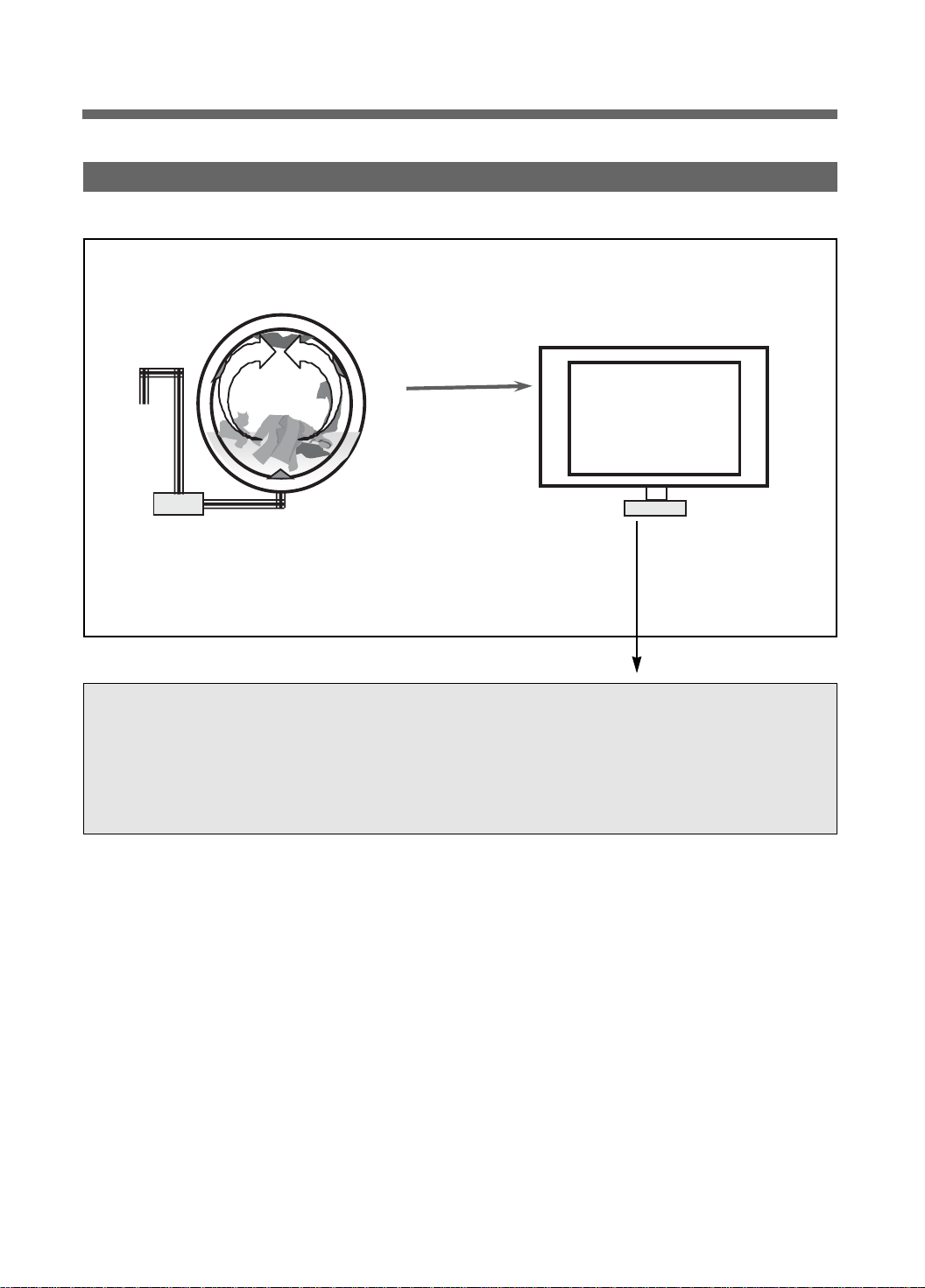
What is Drum Washing Machine?
"
1. Drum Washing Machine
Water consumption is reduced by using the power of the laundry falling (free-fall) created when rotating
the drum resembling a sieve net. With temperature control system, this drum washing machine saves
energy and improves washing performance at the same time.
2. Key Features
" Simultaneous supply of cold#hot water
As cold and hot water is supplied at the same time, heating time and energy is saved.
" DD inverter motor
The direct-drive type, of which motor is directly connected to drum without an interim clutch,
significantly reduces noise and vibration.
" Heating device is installed to enable boiling of the laundry.
" Large door creates grand appearance and makes it easy to put in and out the laundry.
" For pump drainage, the powerful pump speeds up drainage process.
3
Page 4
3. Power System
The
Turbo
Laundry
Drainage Motor
#DD Control: Direct drive type of direct connection between drum and motor
#Rotation by powerful high-performance BLDC motor
#Pump drainage type for built-in installation
Drum
BLDC Motor
4
Page 5

rum Wa
4. Major Functions
$ Washing
When rotating drum after putting in the laundry and detergent into the drum, the laundry are rotated by
protrusions (lifters) attached inside the drum.
Washing is carried out with bending and impact actions generated by falling of the laundry to the top
part of drum.
% Rinsing
Rinsing cleanly washes out detergent and dirt removed from the laundry after washing cycle.
& Spin-drying
Weak, standard and strong cycles can be selected according to types of fabrics to be washed. Spindrying is carried out by rotation (the centrifugal force) of drum according to the designated speed.
' Drainage
Pump Drainage: Powerful pump for built-in installation and application of filter to remove foreign
substances
5
Page 6
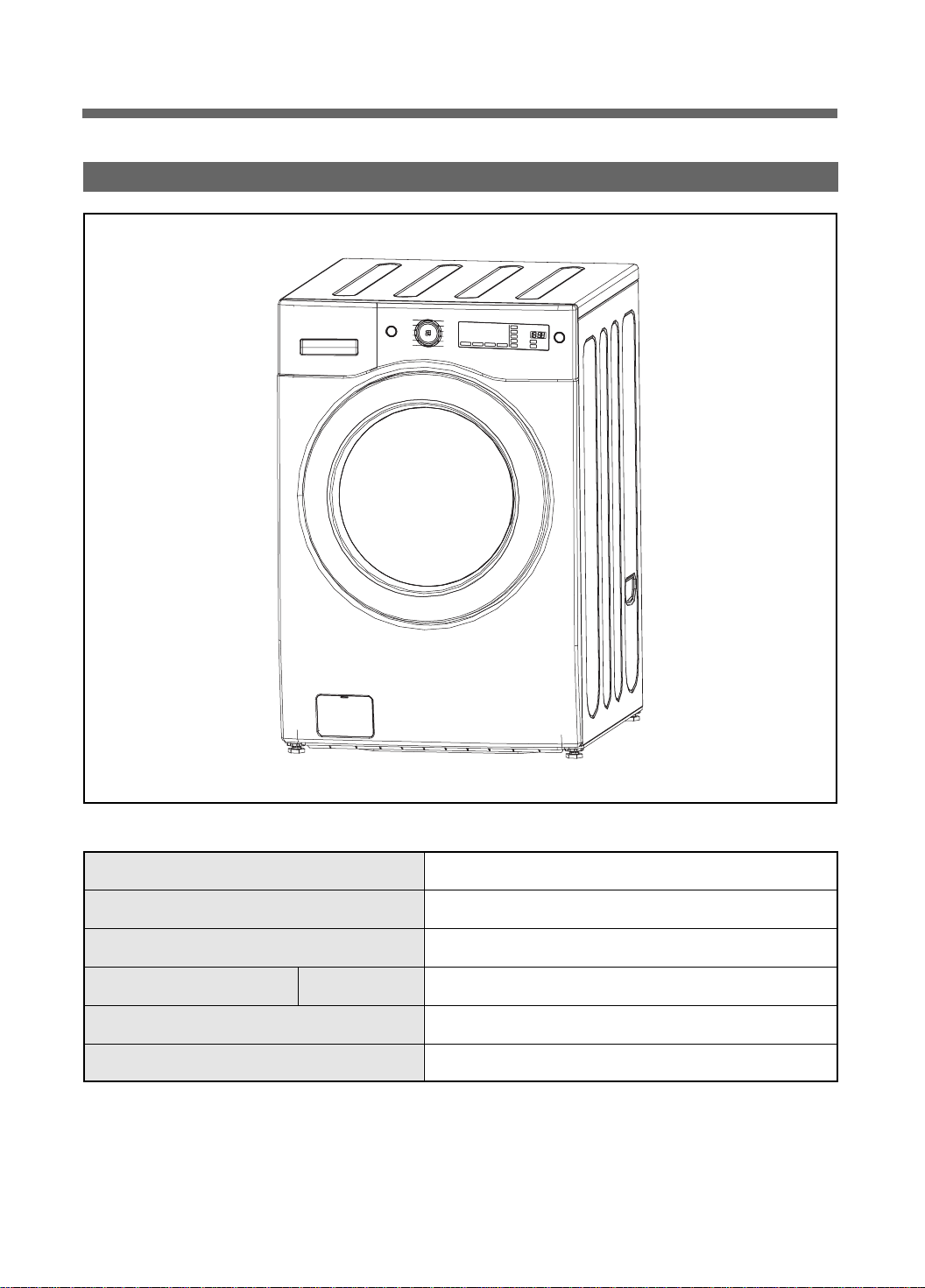
Washer Specification
"
1. Product Specification
External Measurements (inches) 27"(width) x 31.8"(depth) x 40.1"(height)
Weight 198.4lbm
Rated Supply Power 120V 60Hz
Rated Consumption Power Washing 200W (1100W during heating)
Washing Method Drum type
Water Pressure Water Pressure 29kPa ~ 784kPa(0.3kgf/kg~8kgf/kg)
6
Page 7

Operating Mechanism Diagram
"
4. WATER SUPPLY PART
• Cold Water: 3 holes
Cold water, pre-washing
• Hot Water: 1 hole
• Water supply box, hose
5. DOOR
• Door lock S/W
• Lock hinge
• Door AS: Glass
• Gasket
Water
Supply
Delergent
Container
Thermister
Door
Door
Switch
Drainage
Pump
6. DRAINAGE PART
• Drainage pump
• Valve housing
• Hose
Drum
Washing
Heater
Electricity Input
Noise Filter
Thermister
7. SUPPORTER
• Base
• Damper AS: 4
• Spring: 2
Program
BLDC
Motor
1. CONTROL PART
• Main PCB
• Front PCB
• Harness
• Noise filter
• Power Cord: 15A
2. DRIVING PART
• BLDC motor
• Drum
• Bearing
• Spider/ shaft
• Tub
• Weight balancer
3. HEATING PART
• Water Heater: 1000W
• Washing temperature
sensor
7
Page 8
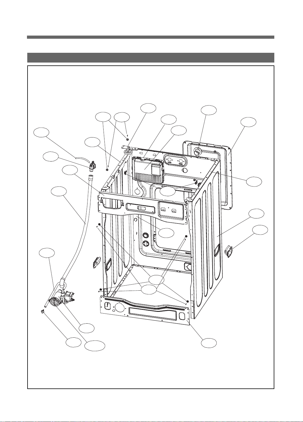
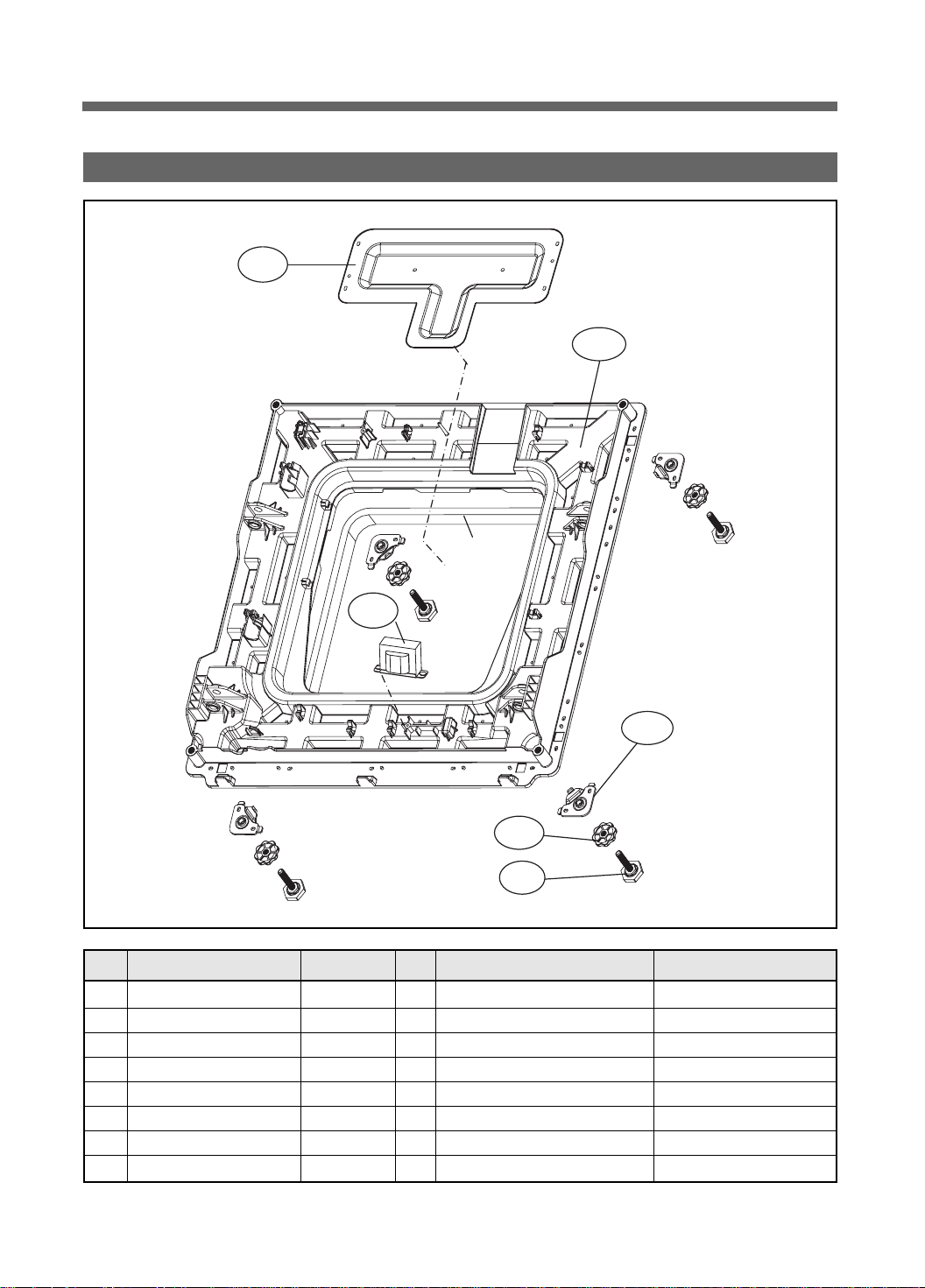
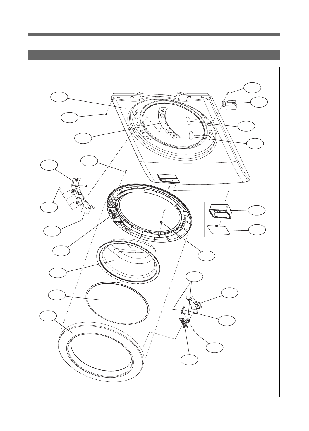
PARTS LIST BY ASS’Y
"
1. CABINET AS
C18
C15
C17
C14
C05
C03
C07
C08
C12
C19
C06
C20
C09
C11
C20
C04
C01
C10
C16
C13
C13-1
C07
C08
C02
8
Page 9
No. Part Name Part Code Qtt'y Specification Remark
- CABINET SUB AS 3610811950 1 13KG, PUMP, WHITE WL6532 XXLW, XXLW RH
3610811955 1 13KG, PUMP, PLATINUM WL6532 XXLPP
3610811956 1 13KG, PUMP, ROSE RED WL6532 XXLRR
3610811957 1 13KG, PUMP, BLACK WL6532 XXLBB
C01 CABINET 3610811740 1 SGCC 0.8T PUMP WASHER • 1PIECE SVC PART
C02 FRAME LOWER 3612206700 1 SBHG 1.2T => CABINET SUB AS
C03 FRAME TOP L 3612206500 1 SGCC 1.6T
C04 FRAME TOP R 3612206600 1 SGCC 1.6T
C05 FRAME UPPER 3612208200 1 SGCC 1.2T
- SCREW TAPPING 7122401411 6 T2S TRS 4 x 14 MFZN Fix Frame Upper to Cabinet
C06 STOPPER SPRING 3615202200 2 POM
C07 FIXTURE PLATE 3612008000 8 POM
C08 SCREW TAPPING 7121401211 8 T2S PAN 4 x 12 MFZN
C09 NOZZLE AIR 3618103110 1 PP
C10 HANDLE CABINET 3612608100 2 PP WL6532 XXLW, PP, RR, BB
C11 COVER BACK AS 3611425510 1 COVER B + PAD
- SCREW TAPPING 7122401411 4 T2S TRS 4 x 14 MFZN Fix Cober Back to Cabinet
C12 SENSOR PRESSURE 3614825220 1 DWD-130RP
- SCREW TAPPING 7122401411 2 T2S TRS 4 x 14 MFZN Fix Sensor Pressure to Cabinet
C13 UNIT DRAIN PUMP AS 36189L5600 1 UL.PLASET + HANYU AS 80W
C13-1 FILTER PUMP 3611910200 1
C13-2 DRAIN PUMP 36196TAP00 1 UL.LOW,80W.20L.1.4A
C13-3 RING O 3614604110 1 D=54,T=2.6
- SCREW TAPPING 7122401411 2 T2S TRS 4 x 14 MFZN
C14 HOSE DRAIN I 3613271300 1 ST+EL, 1010MM
- ABSORBER HOSE DRAIN 3610115600 1 T10, 60 x 130
- CLAMP HOSE 3611203900 2 SK5 D=26 Fix Drain I
C15 HOSE WATER REMAIN 3613272210 1 EPDM, UL 3T Round Bending
C16 CAP WATER REMAIN 3610916800 1 PP
C17 CUFF DRAIN HOSE 3616802600 1 PP, PUMP
C18 HOSE SIPHON 3613272210 1 EPDM, UL 3T L=270
- SCREW TAPPING 7122401411 1 T2S TRS 4 x 14 MFZN Fix Drain Hose to Cabinet
C19 PCB INVERTER AS PRPSSWAD19 1 ASKO 13K Washer Pair main ~ 20091228(changed)
PRPSSWAD1J 1
C20 COVER PCB M 3611427700 1 UL,ABS VE-0856, MAIN PCB
C21 HARNESS AS 3612796T00 1 UL, 13K Washer, Non-bubble ~ 20091228(changed)
3612796T01 1
- SCREW TAPPING 7122401411 1 T2S TRS 4 x 14 MFZN Fix PCB Main to Cabinet
- LOCK HARNESS M 3613802300 6 M Type(18 x 18), Nylon66 Cabinet rear
- LOCK HARNESS 3613802100 2 DASTL-20NA Frame Top right
- LABEL WIRING UL 3613557100 1 UL Only, Wiring diagram+Warning English&French
- SCREW TAPPING 7122401411 1 T2S TRS 4 x 14 MFZN Fix Cabinet F to Frame Lower
13KG, HANYU FILTER + CASE PUMP AS CODE
Fix Drain Pump to Frame Lower
WASHER,PAIR-DRY,RENESAS,USA,ASKO(N.M)
UL 13KG WASHER 3RD-PANEL(BLEACH),NEW MOTECH
20091228 ~
20091228 ~
9
Page 10
rum Wa
2. BASE U ASS'Y
B06
B02
B01
B03
B04
B05
No. Part Name Part Code Qtt'y Specification Remark
B01 REACTOR 52G043A110 1 RT-047K L=150
B02 BASE U 3610392700 1 PP
B03 SUPPORTER LEG 3615303610 4 PO+Coating 3.0T
B04 FIXTURE LEG 3612006400 4 ABS, DWD-100DR
B05 FOOT AS 3612100700 4
B06 PROTECTOR HEATER 3618304600 1 SECC 0.35T
- SCREW TAPPING 7122401411 4 T2S TRS 4x14 MFZN Fix Protector Heater to Base U
- SCREW TAPPING 7122401411 20 T2S TRS 4x14 MFZN Fix Base U to Cabinet
Foot+Special bolt, Double insert type Hybra-Nylon66
10
Page 11
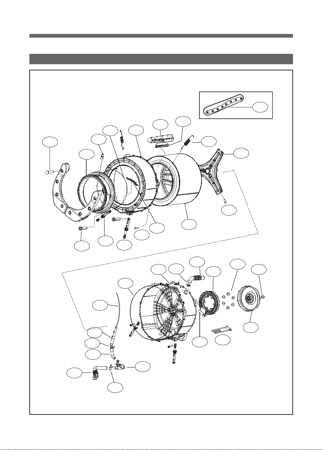
3. SUPPORT DRUM REAR ASS'Y
D06
T01
T03
T12
T04
T05
T11
T10
T21
T06
T07
D04
T09
T20
T23
D05
D01
T22
T08
T24
D02
D03
T26
T28
T13
T18
T17
T16
T15
T14
T19
11
T25
T27
T29
Page 12
rum Wa
No. Part Name Part Code Qtt'y Specification Remark
T01 SPECIAL SCREW 3616029400 8 SWCH 8.5 x 30 Fix Balancer W. to Tub F
T02
BALANCER WEIGHT AS(L)
BALANCER WEIGHT AS(R)
T03 GASKET AS 3612322000 1 EPDM, Wash-only, Nozzle shower
T04 NOZZLE SHOWER 3618104000 1 PP
T05 CLAMP GASKET AS 3611205300 1 Gasket, 13kg Drum
T06 TUB FRONT 3618828Y00 1 FRPP, 13kg Drum
T07 SPECIAL SCREW(TUB) 3616029800 15 SWCH 6.5 x 30 Fix Tub F & R
T08 SPRING SUSPENSION 3615114800 2 13kg DRUM
T09 FIXTURE HEATER 3612006700 1 STS 430
T10 DAMPER FRICTION 361A700300 2
T11 DAMPER FRICTION 361A700110 2
T12 DAMPER PIN 361A700200 8 AKS D=14.5 Tub & Base U
T13 HOSE DRAIN 3613269000 1 EPDM,PUMP
T14 CLAMP HOSE 3611205700 2 HSW3 D2.6 ID33 MFZN
T15 HOSE AIR PRESSURE 3613270600 1 ID=4,OD=8,L=1000MM
T16 HOSE AIR TRAP 3613269700 1 EPDM, 13kg Drum
T17 CLAMP HOSE 3611204700 2 D26
T18 AIR TRAP 361A500101 1 PP
T19 DRAIN HOUSING I 36196TAM00 1 PP,PUMP 1 PIECE SVC PART
T20 TUB REAR AS 36100E2W00 1 DWD-WD113*, DWD-WD123*
T21 GASKET TUB 3612322100 1 EPDM FORM, 13KG DRUM
T22 HOSE AIR 3613266300 1 EPDM, DWD-100DR
T23 CLAMP HOSE 3611205900 2 HSW3 D2.6 ID36 MFZN
T24 UNIT STATOR BLDC 36189L4840 1
T25 HALL IC HOLDER AS 3426D01002 1
- HARNESS SUB AS 3612796D00 1
T26 SPECIAL BOLT AS 3616063400 6 SWCH M8+SILOCK, 58MM Fix Stator & Tub R
T27 UNIT ROTOR BLDC 36189L4900 1
T28 SPECIAL BOLT AS 3616029600 1
T29 HEATER WASH 3612801740 1
D01 DRUM SUB AS 3617008X10 1 SUS, 13kg 1 PIECE SVC PART
D02 SPIDER AS 361A300600 1 13kg, ALDC+S45C
D03 SPECIAL SCREW(SPIDER) 3616029500 6 STS 430, 8 x 25
D04 LIFTER BODY 361A400700 3 PP, 13kg Drum WL6511XXL
D05 CAP FILTER 3610917310 3 ABS, NON-NANO, 13kg 1 PIECE SVC PART
FILTER 3611908410 3 ABS, NON-NANO, 13kg WL6511XXL
FILTER NET 3611908500 3 SUS, FILTER
D06 LIFTER WASH 361A401200 3 PP,13KG 2ND LIFTER,NON-NANO WL6532 XXL
3616110100 1 13KG, VE TYPE, 7.8kg
3616110200 1 13KG, VE TYPE, 7.8kg
AWECO, HP3 60N/9MM BUFFER 4,0
70N AKS ST=170-260 DL=197.5 LOW NOISE
30T,36SLOT,2SENSOR,WS2A30G011
36189L6220 1
3616D01000 1
3612796D20 1
36189L6300 1
AL,DON1400W 32T 36POLE,NMT,PET
DRUM STATOR PCB HOLDER AS(SVC)
DRUM STATOR PCB HOLDER AS(SVC),NMT
130RP SUB HARNESS.MOTOR.HALL.W-TH
SUB HARNESS.NEWMOTECH MOTOR.HALL.W-TH
MAGNET24,SERRATION,WR1238F001
DON1300W SR-FERRITE12,30~32T,NMT
SWCH 10*30,F/L BOLT S.P/W SEAL LOCK
UL.120V1.0KW6.7W/SQ.SUS.1R3A515003.L/W.
Tub F & R right
Tub F & R left
~ 20091228(changed)
20091228 ~
~ 20091228(changed)
20091228 ~
~ 20091228(changed)
20091228 ~
~ 20091228(changed)
20091228 ~
12
Page 13
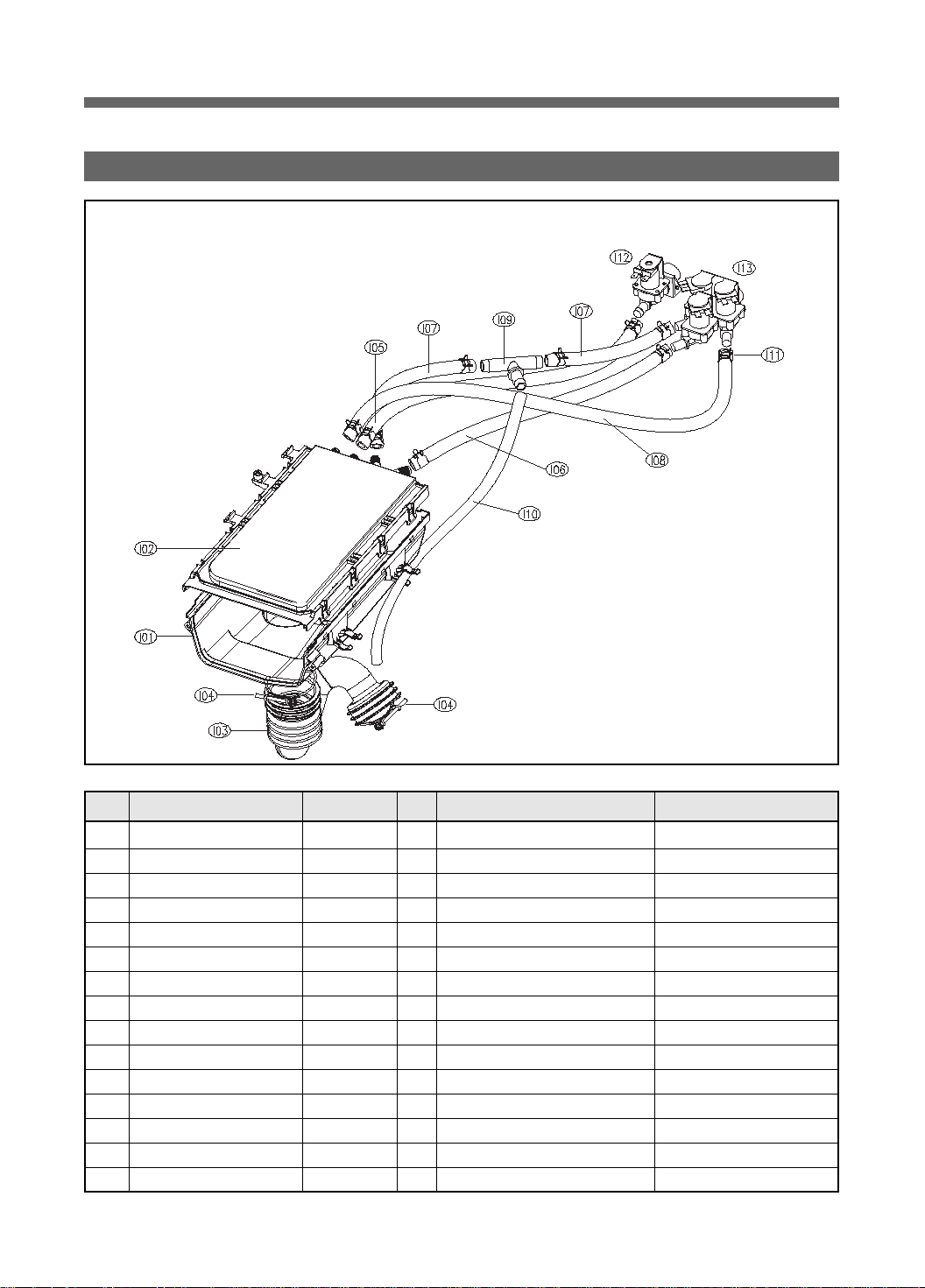
4. INLET BOX AS
No. Part Name Part Code Qtt'y Specification Remark
I01 INLETBOX 3617510800 1 PP
I02 NOZZLE AS 3618104800 1 Top+Under
I03 HOSE INLET 3613270300 1 EPDM
I04 CLAMP AS 3611203200 2 ID=60, WIRE+GUIDE+BOLT+NUT
I05 HOSE WATER SUPPLY 3613270920 1 EPDM ID=9.5 OD=15.5 L=410mm
I06 HOSE WATER SUPPLY 3613270920 1 EPDM ID=9.5 OD=15.5 L=380mm
I07 HOSE WATER SUPPLY 3613270920 2 EPDM ID=9.5 OD=15.5 L=230mm
I08 HOSE WATER SUPPLY 3613270920 1 EPDM ID=9.5 OD=15.5 L=530mm
I09 PIPE JOINT HOSE INLET 3614413300 1 PP
I10 HOSE SHOWER 3613270130 1 EPDM ID=8.5 L=550mm
I11 CLAMP HOSE 3611205810 1 D-WD113'S ID14.3 W10 0.9T WH
I12 VALVE INLET 3615416700 1 UL.120V60HZ.BITRON.1WAY HOT
I13 VALVE INLET 3615416930 1 UL.120V60HZ.BITRON.3WAY COLD
- SCREW TAPPING 7002400811 4 TRS 4X8 MFZN Fix Valve Inlet to Cabinet
- SCREW TAPPING 7122401411 1 T2S TRS 4X14 MFZN Fix Inletbox to Frame T(Side)
13
Page 14
5. CABINET FRONT ASS'Y
F01
F21
F20
F19
F03
F09
F10
F18
F05
F07
F08
F02
F04
F12
F22
F23
F06
F16
F13
F11
F15
F17
F14
14
Page 15
No. Part Name Part Code Qtt'y Specification Remark
F01 CABINET F SUB AS 3610811310 1 13KG, PUMP, WHITE WL6532 XXLW, XXLW RH
3610811321 1 13KG, PUMP, PLATINUM WL6532 XXLPP
3610811322 1 13KG, PUMP, ROSE RED WL6532 XXLRR
3610811324 1 13KG, PUMP, BLACK WL6532 XXLBB
F02 SUPPORTER HINGE 3615304001 1 SGCC 1.2T
F03 LABEL SAFETY R 3613555800 1 PET, DOOR SAFETY,UL
1 PET, DOOR SAFETY,UL, RH XXLW RH
F04 LABEL WARNING 3613558500 1 PET,SILVER,DOOR WARNING,UL
1 PET, DOOR WARNING,UL, RH XXLW RH
F05 FRAME DOOR IN 3612206800 1 PP(Heat resisting)
F06 STOPPER DOOR 3615202300 1 PP(Heat resisting)
F07 DOOR GLASS 361A110600 1 GLASS
F08 PROTECTOR GLASS 3618304300 1 ABS(Transparent)
F09 HINGE DOOR 3612902910 1 ALDC, WHITE WL6532 XXLW, XXLW RH
HINGE DOOR AS 3612902900 1 ALDC, GRAY
F10 CAP HINGE DOOR 3610916500 4 POM
F11 FRAME DOOR OUT 3612206910 1 13K WASHER,ALDC WL6532 XXLW, XXLW RH
3612206900 1 13K WASHER,ALDC
F12 SCREW TAPPING 7115402029 16 T1S FLT 4*20 STS430 NATURAL
F13 COVER HANDLE 3611426720 1 ABS, SPRAY_BASE WL6532 XXLW, XXLW RH
3611426700 1 ABS
F14 HANDLE DOOR 3612609000 1 ABS
F15 HOOK DOOR 3613100800 1 ZNDC
F16 SPRING HOOK 3615113700 2 SUS ID=4.3,NI=7,D=(0.9
F17 PIN HANDLE 3618200100 1 SUS, D3.0
F18 SCREW TAPPING 3616051229 4 STS430 F/L BOLT(SE) 5*12
F19 SWITCH DOOR LOCK 3619046410 1
F20 SCREW TAPPING 7122401608 2 T2S TRS 4 x 16 SUS 430
F21 SCREW TAPPING 7122401411 4 T2S TRS 4 x 14 MFZN For fixing Cabinet F to Cabinet
F22 CASE PUMP 3611141400 1 PP
F23 COVER PUMP 3611426800 1 ABS, WHITE WL6532 XXLW, XXLW RH
DF F11 110 125V 16A PTC-SOLENOID
1 ABS, PLATINUM WL6532 XXLPP
1 ABS, RED WL6532 XXLRR
1 ABS,BLACK WL6532 XXLBB
WL6532 XXLW, XXLPP, XXLRR
WL6532 XXLW, XXLPP, XXLRR
WL6532 XXLPP,XXLRR,XXLBB
WL6532 XXLPP,XXLRR,XXLBB
WL6532 XXLPP,XXLRR,XXLBB
For fixing Door S/W to Cabinet F
15
Page 16
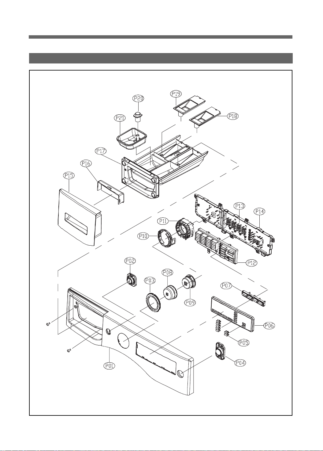
6. PANEL F ASS'Y
16
Page 17
No. Part Name Part Code Qtt'y Specification Remark
P01 PANEL F 3614288800 1 ABS, WASHER(ASKO), WHITE WL6532 XXLW, XXLW RH
1
ABS, WASHER(ASKO), PLATINUM
1 ABS, WASHER(ASKO), RED WL6532 XXLRR
1ABS, WASHER(ASKO), BLACK WL6532XXLBB
P02 BUTTON POWER 3616637800 1 ABS, WHITE WL6532 XXLW, XXLW RH
1 ABS, PLATINUM WL6532 XXLPP
1 ABS, RED WL6532 XXLRR
1ABS, WASHER(ASKO), BLACK WL6532XXLBB
P03 WINDOW COURSE 3615506300 1 ABS(Transparent) + Film, WHITE WL6532 XXLW, XXLW RH
1
ABS(Transparent) + Film, PLATINUM
1 ABS(Transparent) + Film, RED WL6532 XXLRR
1ABS, WASHER(ASKO), BLACK WL6532XXLBB
P04 BUTTON START 3616637900 1 ABS, WHITE WL6532 XXLW, XXLW RH
1 ABS, PLATINUM WL6532 XXLPP
1 ABS, RED WL6532 XXLRR
1ABS, WASHER(ASKO), BLACK WL6532XXLBB
P05 BUTTON OPTION 3616638100 7 ABS, WHITE WL6532 XXLW, XXLW RH
7 ABS, PLATINUM WL6532 XXLPP
7 ABS, RED WL6532 XXLRR
1ABS, WASHER(ASKO), BLACK WL6532XXLBB
P06 WINDOW DISPLAY 3615506400 1 ABS(Transparent) + Film, WHITE WL6532 XXLW, XXLW RH
1
ABS(Transparent) + Film, PLATINUM
1 ABS(Transparent) + Film, RED WL6532 XXLRR
1ABS, WASHER(ASKO), BLACK WL6532XXLBB
P07 BUTTON FUNCTION 3616638000 1 ABS, WHITE WL6532 XXLW, XXLW RH
1 ABS, PLATINUM WL6532 XXLPP
1 ABS, RED WL6532 XXLRR
1ABS, WASHER(ASKO), BLACK WL6532XXLBB
P08 DIAL KNOB OUTER 3616638200 1 ABS, WHITE
1 ABS, PLATINUM
1 ABS, RED
1ABS, WASHER(ASKO), BLACK
P09 DIAL KNOB INNER 3616638300 1 ABS, WHITE
1 ABS, PLATINUM
1 ABS, RED
1ABS, WASHER(ASKO), BLACK
P10 LED COURSE 3613054700 1 ABS(Transparent)
P11 HOLDER COURSE 3613054500 1 ABS
P12 HOLDER FUNCTION 3613054600 1 ABS
P13 PCB AS PRPSSWAD29 1 ASKO Washer Front PCB As
P14 CASE PCB FRONT 3611147600 1 ABS
- SCREW TAPPING 7122401829 2 T2S TRS 4x18 STS
- SCREW TAPPING 7122401411 7 T2S TRS 4x12 MFZN For fixing PCB AS to Panel F
P15 CASE HANDLE 3611147700 1 ABS, Silk print, WHITE WL6532 XXLW, XXLW RH
1 ABS, Silk print, PLATINUM WL6532 XXLPP
1 ABS, Silk print, RED WL6532 XXLRR
1ABS, WASHER(ASKO), BLACK WL6532XXLBB
P16 HANDLE CAP 3612611400 1 ABS, WHITE WL6532 XXLW, XXLW RH
1 ABS, PLATINUM WL6532 XXLPP
1 ABS, RED WL6532 XXLRR
1ABS, WASHER(ASKO), BLACK WL6532XXLBB
P17 CASE DETERGENT 3611145600 1 PP
P18 CAP SOFTENER 3610917800 1 PP
P19 CAP BLEACH 3610917900 1 PP
P20 CAP LIQUID 3610918000 1 PP
P21 CASE LIQUID 3611145700 1 PP
17
WL6532 XXLPP
WL6532 XXLPP
WL6532 XXLPP
For fixing Panel F to Frame Upper
Page 18
7. PLATE T ASS'Y
E01
E02
No. Part Name Part Code Qtt'y Specification Remark
E01 PLATE TOP 3614533020 1 SECD 1.0T, WHITE WL6532XXLW
1 SECD 1.0T, PLATINUM WL6532XXLPP
1 SECD 1.0T, RED WL6532XXLRR
1 SECD 1.0T, BLACK WL6532XXLBB
E02 HANDLE REAR 3615304100 2 ABS WL6532XXLW
(PLATE SUPPOTER) 3615304120 2 13KG, ABS,GY-6702A WL6532XXLRR, PP,BB
- SCREW TAPPING 7122401411 4 T2S TRS 4x14 MFZN
18
Page 19
rum Wa
8. ACCESSORY
A01 A02 A03 A04 A05
No. Part Name Part Code Qt'y Specifications Color Cost in USD($) Remarks
A01 HOSE DRAIN O AS 3613268500 1 DWD-800W, L=1,500 NA
GUIDE DRAIN HOSE 3612502300 1 PP NA
A02 HOSE INLET AS 3613271500 1 REFLEX, PVC 1.3M NA Cold
HOSE INLET AS 3613271510 1 REFLEX, PVC 1.3M NA Hot
A03 UNIT SVC WRENCH 36189L3X00 1 PO+Coating, 2.3T DWD-110RP NA
A04 MANUAL OWNERS 4589A61600 1 ASKO Manual NA English & French
A05 CAP HOLDER 3610916400 4 PP, DWD-10RP White
19
Page 20
Control Part Function Spec
"
1. SEQUENCE CHART
CCllaassssiiffiiccaattiioonn PPrroocceessssiinngg TTiimmee
PP
rr
ee
WW
aa
ss
hh
WW
aa
ss
hh
RR
ii
nn
ss
ee
SS
pp
ii
nn
EEnndd
Sensing 10sec
Water Supply 2min
Pre-Wash 10min
8min
Drain 1min
Balancing Spin 2min
Middle Spin 3min
Sensing 20sec
Water Supply 2min
"Main-Wash 1 50min 98min 102min
(Heating)" 45min
30min 27min
25min 18min 22min 16min 17min
15min 20min
Drain 1min
Balancing Spin 2min
Middle Spin 3min
Water Supply 2min
Rinse 1 4min
Drain 1min
Balancing Spin 2min
Middle Spin 3min
Water Supply 2min
Rinse 2 4min
Drain 1min
Balancing Spin 2min
Middle Spin 3min
Water Supply 2min
Rinse 3 4min
Drain 1min
Balancing Spin 2min
Spin 9min
7min
6min
Clothes Release 60sec
End 10sec
Remain Time Display 55 59 53 54 2:15 2:19 1:04 57
NOTE
1. Normal : W/C + Wash + Soil Normal + Rinse 2 + Medium Spin
2. Cotton : W/C + Wash + Soil Normal + Rinse 2 + Ex.High Spin
3. Sanitary : E.H/C + Wash + Soil Normal + Rinse 2 + Medium Spin
4. Bulky : C/C + Wash + Soil Normal + Rinse 2 + Medium Spin
5. White : W/C + Wash + Soil Normal + Rinse 2 + Medium Spin
EEvveerryyddaayy TToowweell SSaanniittaarryy
Small Low Small Low Small Low
BBuullkkyy SSyynntthheettiicc
20
Page 21
rum Wa
CCllaassssiiffiiccaattiioonn PPrroocceessssiinngg TTiimmee
PP
rr
ee
WW
aa
ss
hh
WW
aa
ss
hh
RR
ii
nn
ss
ee
SS
pp
ii
nn
EEnndd
Sensing 10sec
Water Supply 2min
Pre-Wash 10min
Drain 1min
Balancing Spin 2min
Middle Spin 3min
Sensing 20sec
Water Supply 2min
"Main-Wash 1 50min
(Heating)" 45min
Drain 1min
Balancing Spin 2min
Middle Spin 3min
Water Supply 2min
Rinse 1 4min
Drain 1min
Balancing Spin 2min
Middle Spin 3min
Water Supply 2min
Rinse 2 4min
Drain 1min
Balancing Spin 2min
Middle Spin 3min
Water Supply 2min
Rinse 3 4min
Drain 1min
Balancing Spin 2min
Spin 9min
Clothes Release 60sec
End 10sec
Remain Time Display 1:12 32 30 57 33
NOTE
1. Heavy Duty : W/C + Wash + Soil Heavy + Rinse 2 + Medium Spin
2. Delicate : C/C + Wash + Soil Normal + Rinse 1 + Low Spin
3. Wool : C/C + Wash + Soil Light + Rinse 1 + Low Spin
4. Perm Press : W/C + Wash + Soil Normal + Rinse 2 + Low Spin
5. Speed Wash : C/C + Wash + Soil Light + Rinse 1 + Low Spin
6. Drum-Cleaning : C/C + Wash + Soil Light + Rinse 2 + Low Spin
HHeeaavviillyy SSiillkk WWooooll WWhhiittee QQuuiicckk
8min
30min 35min
25min 22min
15min 8min 6min 8min
7min
5min
21
Page 22
2. Composition per Function
2-1. Water Supply
1) Water Temperature Selection
Water supply algorithm differs according to water temperature selected among 5 levels.
In other temperatures, with the exception of cold water, constant temperature control is executed.
Cold water and hot water operation is carried out in turn according to the target temperature.
Water T emp. T arget Temp. T arget 1 T arget 2
Extra Hot 67) 67) 70)
Hot 35) 34) 36)
Warm* 30) 29) 31)
Warm 30) 29) 31)
Cold - - -
2) For Cold, valve operation does not change according to temperature and only the time unit of
cold on for 7sec and off for 9sec is set to supply cold water per each unit of 16sec.
3) How to Insert Bleach
- During Washing
Operation for 12sec after 3-minute washing in Wool, Silk and Quick wash courses
Operation for 12sec after 5-minute washing in Towel course
Operation for 12sec after 9-minute washing in other courses
22
Page 23
rum Wa
2-2. Drainage
1) Pump Operation - Washing cycle
$ Before Drainage Completion: Pump continuously on
% Spin-drying Cycle after Drainage Completion
: On for 18sec and off for 3sec
2-3. Sensor Detection
1) Water Level Sensor Data
Classification Height Frequency
Water Level (mm) (KHz)
Spec. Small 130 24.62
Spec. Low 130 24.62
Washing Small 130 24.38
Washing Low 130 24.09
Standard Rinsing 160 24.27
Rinsing 160 23.64
Additional Rinsing 175 24.01
Tub Washing 195 23.77
Overflow 260 22.6
Safety 125 24.7
Reset 125 24.68
Remarks
23
Page 24
2) Temperature Sensor Data
Temp. Resistance(**)Voltage
0 35.97 0.58
10 22.76 0.86
20 14.77 1.21
22 13.57 1.29
24 12.48 1.37
25 11.98 1.41
27 11.04 1.49
29 10.18 1.58
30 9.78 1.62
32 9.04 1.71
34 8.36 1.80
36 7.74 1.89
38 7.17 1.98
40 6.65 2.07
49 4.7 2.50
55 3.85 2.75
60 3.24 2.96
65 2.74 3.16
75 1.99 3.51
Remarks
24
Page 25

rum Wa
2-4. How to Control Voltage (during abnormal operation)
1) Voltage Control
$ Normal Voltage
DC-link voltage after wave rectification is directly impressed to IPM as 310 ~ 330V.
When motor starts operation, DC voltage changes with energy consumed by motor and/
or counter electromotive force of motor.
% Identifying Abnormal Voltage
A. Occurrence of counter electromotive force
+ In case of 450V or higher
B. Instant power failure and excessive energy consumption
+ In case of 185V or lower
2-5. How to Control Current (during abnormal operation+B227)
1) Current Abnormality Detection
$ Abnormal if DC current flowing through IPM measured during high-speed motor rotation is
10A~12A or higher
% Detection of abnormal current to be carried out by saving higher value among instant current values
and updating the data
25
Page 26

2-6. Door S/W
1) Door S/W Operation
$ Door Locking
3sec after bi-metal operation of door S/W, pulse of 20msec duty on solenoid is impressed twice until
door is locked. Bi-metal begins operation simultaneously as power button is pressed.
% Door Unlocking
Bi-metal plate of door S/W is turned off and pulse of 20msec duty on solenoid is impressed until door is
unlocked.
& Motor or other electronic parts begin operation to execute normal cycles only when door is locked.
' Door is closed if temperature measured by washing temperature sensor after turning on power button
is 55) or higher or if water level is higher than safety level.
, Door is opened immediately when cycle is finished.
- During cycle suspension, door is opened anytime if allowable by conditions.
2) Door Open System
$ To forcefully open door in order to additionally insert the laundry during washing, door can be
opened by pressing unlock clear button.
% Door open system by unlock clear button is to forcefully open door when not in conditions for door
opening. It begins the sequence to satisfy conditions for door opening.
26
Page 27

rum Wa
2-7. Load Sensing
1) Load Sensing to Determine Water Level
$ Á Load sensing is carried out when selecting standard, boiling and thrifty boiling courses.
% Sensing is administered in the dry laundry state before starting of washing cycle.
& After motor operation at 75 r.p.m for 10sec, load is judged with motor output measured.
2) Load Sensing for B Spin-drying
$ Sensing is administered with the laundry wet during the first interim spin-drying after completion of
washing cycle.
% After motor operation at 75 r.p.m for 10sec, load is judged with motor output measured.
& Base values for B spin-drying unbalance of interim and main spin-drying are selected according to
load measured by sensing.
2-8. Child Lock
$ Child lock mode begins by pressing 'Beeper' button during cycle. % In child lock mode, all buttons,
with the exception of power button, are not operated.
& In child lock mode, cycle display window is lit to show that child lock has been applied. Also, the
remaining time is displayed in '18:88' window.
' Lock mode is cleared by pressing 'Beeper' button as was done when starting child lock mode.
27
Page 28

3. Functions per Cycle
3-1. Washing Cycle
1) Classification of Washing
$ Pre-washing and soaking are carried out before main washing cycle.
% Decided value refers to water level and time decided by load sensing in standard, boiling and thrifty
boiling courses. In other sources, it means the pre-set time according to the designated water level.
& Soaking is the cycle consisted with water supply and washing only. Main washing begins
immediately after this cycle without drainage.
' In pre-washing and soaking cycles, only cold water is used and heating is not administered.
2) Heater Operation
$ Washing heater does not re-operate once turned off after reaching the set temperature.
% Even when target water temperature is not reached, washing cycle is finished when washing time
expires.
3) Re-supply of water
$ Re-supply is carried out in case water level detected per 2 minute after water supply completion is
lower than the set water level.
% Motor is stopped during re-supply.
& During washing, re-supply is carried out up to 10 times. After the 10th time, re-supply is not
administered even if water level drops.
' Re-supply is not carried out if more than half of washing time has passed and heater is turned off.
28
Page 29

rum Wa
3-2. Rinsing Cycle
1) Water Supply Cycle
$ When selecting 'add water for rinsing', water is supplied to the water level of additional rinsing.
% Only cold water is supplied in rinsing cycle.
& In the last rinsing, fabric softener is inserted by opening both cold water V/V and pre-washing V/V at
the same time.
2) Re-supply of Water
$ Water level is checked 1 minute after starting of rinsing cycle. Then, water is re-supplied up to the
designated water level.
3) Drainage
$ To administer drainage after completing washing at water temperature of 55) or higher, drainage is
carried out after dropping water temperature by supplying cold water to high level.
% When drainage cycle begins, drainage motor is continuously kept on.
4) Interim Spin-drying
$ Interim spin-drying is administered up to the r.p.m designated per each course.
The following cycle begins if R spin-drying is not reached after 20 times of balance spin-drying.
% After completion of washing cycle, load sensing is carried out before the first interim spin-drying to
detect load. Then, the cycle proceeds to main spin-drying by differing standard unbalance values
according to the load.
29
Page 30

3-3. Spin-drying Cycle
1) Drainage
$ Drainage set time is 1min.
% When drainage is completed, 1 minute is reduced from the overall cycle.
2) Balance Spin-drying
$ Spreading the laundry : Rotating the same 45rpm with left and right direction altematively.
% Attaching stop : Attaching the laundry to drum inside with constant speed.
& Unbalance checking point : First step, check the U.B at 95 rpm, 160rpm
Second step,check the U.B at 95 rpm, 350rpm
Third step, at 300rpm. if the unbalance data is over the criterion
This process will be rpeated
' Drain step : Drain at water around 160rpm
, After drain, check the unbalance data again. This is so-called balance spin step.
3) R (Real) Spin-drying
$ 'R spin-drying' refers to the process until completion of spin-drying after B spin-drying.
% The r.p.m reached differs according to the spin-drying cycle selected.
& When acceleration ends during spin-drying, constant-speed operation is carried out at the r.p.m set in
the selected cycle. Breaking is carried out after deceleration to app. 450 r.p.m.
' When stopping cycle by pressing temporary stop button during spin-drying, breaking is carried out to
stop motor.
, Max. r.p.m operation time according to spin-drying selection
Spin-Drying Classification Max. r.p.m Time of Max. r.p.m Maintenance Remarks
Low 550 r.p.m 380sec
Medium 850 r.p.m 345sec
High 1100 r.p.m 115sec
Extra High 1300 r.p.m 60sec
4) No Drainage
$ Cycle is completed without drainage after rinsing is finished
30
Page 31

rum Wa
3-4. Ending
1) Untwisting
$ This cycle aims to prevent creasing by loosening the laundry attached to the inner wall of drum after
completion of spin-drying. Untwisting is carried out for 30sec.
% Motor is operated according to the water stream of untwisting.
2) Ending
$ After completion of untwisting, buzzer is sounded for 10sec and power is turned off.
% In case additional drying cycle has been set, drying cycle is carried out after untwisting.
& After ending process begins, door lock is cleared.
31
Page 32

4. Button Functions
4-1. Power
1) This electronic power switch turns on/ off display.
2) Automatic Power Switch Off
$ Power is turned off immediately after completion of entire cycles or the selected cycle.
% Power is automatically turned off in 10 minutes if no button control is made after power on.
3) Initial Display for Power Only
$ Course LED is turned on for 1sec.
% 18:88 LED displays '---'.
4-2. Start / Stop
1) Normal course begins when pressing button after turning on power S/W.
2) Operation begins by pressing button after setting a program course or automatic course of 10 varieties.
3) If button is pressed during operation, blinking of cycle lamp changes to lighting only and operation
stops. When button is pressed again, operation restarts from the point of temporary suspension.
4) If cycle is changed by controlling button or encoder switch in temporary suspension state, the mode is
changed to the initial mode.
5) Lock is cleared if in the corresponding conditions by judging values of washing temperature sensor or
water level during temporary suspension.
32
Page 33

rum Wa
4-3. Wash
1) Range of temp. selection differs according to the course selected. If you select Cold, the washing
temperature will be the same as that of the machine's water supply.
Each program the temperature it will be able to select is restricted.
(Refer to Washer Program Default Data and Select Option.)
2) The text displayed indicates water temperature for washing. "Cold water is used for rinsing.
When ‘Warm*’ is selected, warm temperature is maintained for both washing and rinsing."
3) Cold water and hot water supply method differs according to water temperature selection.
Heating temperature also differs.
4) For sanitary course, water temperature is fixed at 'Extra Hot'.
Wash Temperature Wash / Rinse
Extra Hot 67
Hot 35
Warm* 30
Warm 30
Cold - NO Heating
4-4. Soil Level
1) When pressing button, LED is repetitively lit in the order of ‘Normal _ Heavy _ Extra
Heavy _ Off _ Extra Light _ light'
2) Soil level can be selected only when washing cycle is set.
3) Soil level is operated in courses other than 'Wool/Handwash' and 'Quick Wash'.
4) Washing time changes according to the selected soil level.
)
)
)
)
Extra. Hot / Cold
Hot / Cold
Warm / Warm
Warm / Cold
5) Selection can be changed during cycle after temporary suspension.
6) Overall cycle time is shown in 18:88 display.
33
Page 34

4-5. Spin Speed
1) When pressing button, LED is repetitively lit in the order of " Medium. High. Extra High
. Off. No Spin. Low'.
2) 18:88 display shows the remaining time.
3) During cycle, selection change is possible after temporary suspension.
4-6. Signal
1) Signal button operates in 5 steps.
Press Signal to adjust the sound level or turn off the signal.
2) After change, it is saved in EEPRPM.
4-7. Pre-Wash
1) Button is operated only when washing is selected.
2) Pre-wash is not available in Wool/Handwash, Quick Wash courses.
3) When pressing button, pre-wash is added and LED is lit. LED is turned off when pressing
the button again.
4) Pre-wash LED is turned off when pre-wash is completed.
34
Page 35

rum Wa
4-8. Extend Wash
1) When button is pressed, washing time increases per washing course, such as by 6 minutes for 'heavily',
8 minutes for 'sanitary', 5 minutes for 'everyday wear' and 'towel' and 4 minutes in other cases.
2) Extra wash is not available in Silk/Gentle, Quick Wash, Wool/Handwash courses.
3) Extra wash LED is turned off when washing is completed.
4-9. Extra Rinse
1) Extra rinse is not available in Quick wash courses.
2) When pressing button rinsing cycle is added by once and LED is lit. When pressing button
again, rinsing cycle decreases by once and LED is turned off.
3) Extra rinse LED is turned off when rinsing is completed.
4-9. Rinse+Spin
1) When pressing button, rinsing once + spin medium is selected.
2) Operation does not return to previous cycle even when pressing the button again.
The cycle set in the corresponding course is displayed by rotating course dial.
Then, rinse spin LED is turned off.
4) Water temperature can be selected with Temp. button after rinse + spin is set.
Selection can be made from Cold to Warm.
5) Even after rinse + spin is selected, water temperature selection can not be made in
Wool/Handwash courses.
6) When cycle is completed, LED is turned off.
35
Page 36

4-10. Night Time
1) When pressing button, spin speed is set as low and interim spin-drying changes from
790 r.p.m. to 550 r.p.m.
2) When pressing button again, set values of interim spin-drying and main spin-drying mode
courses are resumed.
3) LED is turned off when the cycle is completed.
4-11. Delay Start
1) Preset time indicates starting time of the entire cycle.
2) When pressing preset button, time changes in the order of 1.2.3. 4 ….12.1.
3) After selecting preset time, cycle change is possible before entering preset mode by pressing start/stop
button. However, cycle cannot be changed after entering preset mode.
4) To preset operation, select cycle.select preset time.press start/stop button.
5) The selected cycle is displayed for 3 seconds when pressing start/stop button after
entering preset mode to check the selected cycle.
4-12. Child Lock**
1) During an operation of washer, press 'Child Lick' button simultaneously during 3 second.
2) If this mode will be set successfully, Child Lock Lamp will be burn out. In Child Lock mode,
no button functions except Power button.
3) if you want to release this mode, press 'Child Lock' button simultaneously again during 3 second.
36
Page 37

rum Wa
4-13. Course Selection Switch
1) Everyday Wear course selected by clicking switch once after power is turned on.
2) Per each click after the first, course is selected in the direction of CW or CCW.
3) 18:88 display indicates cycle time of each course.
4-14. Washer Program Default Data and Select Option
Heavily
Sanitary
Bulky
Everyday
White
Synthetic
Towel
Silk
Quick
Wool
default
selection
default
selection
default
selection
default
selection
default
selection
default
selection
default
selection
default
selection
default
selection
default
selection
Temp
Warm*
Cold~Hot
Ex.hot
X
Warm
Cold~Warm*
Warm
Cold~Hot
Warm
Cold~Hot
Warm
Cold~Hot
Warm
Cold~Hot
Cold
X
Cold
Cold~Warm*
Cold
X
Soil
Normal
Ex.light~Ex.heavy
Normal
Ex.light~Ex.heavy
Normal
Ex.light~Ex.heavy
Normal
Ex.light~Ex.heavy
Normal
Ex.light~Ex.heavy
Normal
Ex.light~Ex.heavy
Normal
Ex.light~Ex.heavy
Normal
Ex.light~Ex.heavy
Ex.light
X
Ex.Light
X
Spin
High
no spin~Ex.high
Medium
no spin~Ex.high
Medium
no spin~High
Medium
no spin~Ex.high
Medium
no spin~Ex.high
Low
no spin~Ex.high
Ex.High
no spin~Ex.high
Low
no spin~Medium
Low
no spin~Medium
Low
no spin~Low
Pre
Wash
O
O
O
O
O
O
O
O
X
X
Extended
Wash
O
O
O
O
O
O
O
X
X
X
Extra
Rinse
O
O
O
O
O
O
O
O
X
O
Rinse+Spin, Delay
start, Night time
O
O
O
O
O
O
O
O
O
O
37
Page 38

rum Wa
5. PCB Manual Test Mode
- PCB and other electronic parts will be tested without water supply whether they are normal or not.
1) Process
: Press power button -> Press "SPIN" button 3 times with pressing "WASH" button -> "X X X" will be
shown on LED display-> Whenever pressing "Signal" button 1 time, below process will be occurred.
- "X X X' : Program version display
Step Display Details
" #$% &''(!#')*!%+',-
. (/0 11" 2/00304!536-,!)'/05
78"19:##;<=><?2!=22?2!)'/05
@8.1ABC;D:E#F!=22?2!)'/05
G871?H-(;+'IJ!=22?2!)'/05
K8@1C'5'(!I+340!=22?2!)'/05
L8G12M6!)N-)*304!=22?2!)'/05
O8K1?H-(H'+5I4-!=22?2!)'/05
P8L1#'Q!H'+5I4-!=22?2!)'/05
"1 D D:>!RDR
"" 9 9'5!SI+H-
". % %'+J!SI+H-
"7 B B(-!TI,N!SI+H-
"@ J >'!/,-
"G 88 U+-I)N!SI+H-
"K J( &(I30!B/6M
"L #$? #')*!?M-0
2) More details
- When turn on 'LOCK' signal, all process is conducting normaly.
- In this case, BLDC Motor is not tested. In order to test it, select spin or rinse.
38
Page 39

6-1. IE (Input Error) - Error in water supply
6-1. IE (Input Error) - Error in water supply
1) Conditions of Occurrence
$ In case the designated water level is not reached in 5 minutes during water supply or re-supply
2) All LEDs are turned off and 'IE' blinks in18:88 display.
3) Error buzzer alarm is sounded for 10 seconds per every 10 minutes.
4) Error display is cleared when turning off/ on power.
6-2. OE (Output Error) - Error in drainage
1) Conditions of Occurrence
$ In case water level does not reach reset point in 10 minutes after drainage starts
2) All LEDs are turned off and 'OE' blinks in 18:88 display.
3) Error buzzer alarm is sounded for 10 seconds per every 10 minutes.
4) Error display is cleared when turning off/ on power.
6-3. UE (Unbalance Error)
1) Conditions of Occurrence
$ In case main spin-drying is not reached within 20 cycles of balance spin-drying
% In case balance spin-drying fails during interim spin-drying, UE occurs as the cycle moves to the next
process.
2) All LEDs are turned off and 'UE' blinks in 18:88 display.
3) Error buzzer alarm is sounded for 10 seconds per every 10 minutes.
4) Error mode is cleared by opening door and organizing the laundry in spin-dry chamber, closing door and
pressing start/ temporary stop button. Then, spin-drying begins again.
39
Page 40

rum Wa
6-4. LE (Lock Error) - Door opening error
1) Conditions of Occurrence
$ When intending to begin cycle by pressing start/ temporary stop button while door is opened
2) All LEDs are turned off and 'LE' blinks in 18:88 display.
3) Error buzzer alarm is sounded for 10 seconds per every 10 minutes.
4) Error display is cleared when turning off/ on power.
6-5. E1 - Water level detection error
1) Conditions of Occurrence
$ In case water level is below reset or overflow is detected in line test mode
2) Water supply motor is kept on until water level falls below reset.
3) All LEDs are turned off and 'E1' blinks in 18:88 display.
4) Error buzzer alarm is sounded for 10 seconds per every 10 minutes.
5) Error display is cleared when turning off/ on power.
6-6. E2 - Overflow error
1) Conditions of Occurrence
$ In case water level in water tank is above overflow level due to continuous operation of water supply
valve
2) Water supply motor is kept on until water level falls below reset.
3) All LEDs are turned off and 'E2' blinks in 18:88 display.
4) Error buzzer alarm is sounded for 10 seconds per every 10 minutes.
5) Error display is cleared when turning off/ on power.
40
Page 41

6-7. E4 - Water leakage during washing
1) Conditions of Occurrence
$ In case water level falls below re-supply even after 15 times of re-supply prior to finishing of water
heating
2) All LEDs are turned off and 'E4' blinks in 18:88 display.
3) Error buzzer alarm is sounded for 10 seconds per every 10 minutes.
4) Error display is cleared when turning off/ on power.
6-8. E9 - Abnormalities in water level sensor
1) Conditions of Occurrence
$ In case water level frequency is of 15KHz or lower and 30KHz or higher during cycle due to
abnormalities in water level sensor, etc.
2) All LEDs are turned off and 'E9' blinks in 18:88 display.
3) Error buzzer alarm is sounded for 10 seconds per every 10 minutes.
4) Error display is cleared when turning off/ on power.
41
Page 42

rum Wa
6-9. Motor-related Error
1) E5 (DC-Link High Voltage) Error
$ In case DC-link voltage to IPM increases to 450V or higher
% Motor operation is stopped and 'E5' is shown in display window.
& Error buzzer alarm is sounded for 10 seconds per every 10 minutes.
' Error display is cleared when turning off/ on power.
2) E6 (EMG) Error
$ In case current detected with EMG port is of 20A or higher
% Motor operation is stopped and 'E6' is shown in display window.
& Error buzzer alarm is sounded for 10 seconds per every 10 minutes.
' Error display is cleared when turning off/ on power.
3) E7 (Direction) Error
$ In case signal of Hall IC is different from the predicted signal according to direction of rotation
% Motor operation is stopped and 'E7' is shown in display window.
& Error buzzer alarm is sounded for 10 seconds per every 10 minutes.
' Error display is cleared when turning off/ on power.
4) E8 (Initial Operation Fail) Error
$ In case input signal of Hall IC is abnormal due to problems in motor connection, etc.
% Motor operation is stopped and 'E8' is shown in display window.
& Error buzzer alarm is sounded for 10 seconds per every 10 minutes.
' Error display is cleared when turning off/ on power.
6-10. Error in Temperature Sensor
1) H2 Error - Washing temperature sensor open/ short
$ In case washing temperature sensor is defective or not connected
% Error buzzer alarm is sounded for 10 seconds per every 10 minutes.
& Error display is cleared when turning off/ on power.
2) H4 Error - Washing temperature sensor overheating
$ In case temperature detected by washing temperature sensor is 95) or higher
% Error buzzer alarm is sounded for 10 seconds per every 10 minutes.
& Error display is cleared when turning off/ on power.
42
Page 43

3) H5 Error - Water temperature error in wool/ delicate course
$ In case water temperature in wool/ delicate course is 45) or higher
% Error buzzer alarm is sounded for 10 seconds per every 10 minutes.
& Error display is cleared when turning off/ on power.
4) H6 Error - Abnormality in washing heater
$ Within 15 minutes after heater operation begins;
In case standard temperature is of 42) or lower: If temperature does not increase by 2) or more In
case standard temperature is higher than 42): If temperature does not increase by1) or more
% If temperature falls below standard temperature by 2) or more due to re-supply of water, etc.,
standard temperature is reset as the current temperature and error check time of15 minutes is reset.
& Error buzzer alarm is sounded for 10 seconds per every 10 minutes.
' Error display is cleared when turning off/ on power.
5) H8 Error - Washing heater overheating
$ In case washing heater temperature increases by 5) or more within 30 seconds when there is no
water in tank, etc.
% Error buzzer alarm is sounded for 10 seconds per every 10 minutes.
& Error display is cleared when turning off/ on power.
6-11. PFE (Pump Filter Error)
$ Cycle is skipped to the next when the current r.p.m. is different from the target r.p.m by 70 during
interim spin-drying.
% Cycle is skilled to balance spin-drying when the current r.p.m is different from the target r.p.m by 70
during main spin-drying.
& 'PFE' error is caused if main spin-drying skip of % above occurs 10 times.
' Error display is cleared when turning off/ on power.
43
Page 44

PCB PIN ARRANGEMENT
"
44
Page 45

Detailed Spec, Principles and Breakdown Diagnosis/ Service of Electronic parts
"
1. VALVE INLET
CCllaassssiiffiiccaattiioonn
Code
Color
Coil Resistance
Use
Appearance
Structure
SSyymmppttoommss ooff
BBrreeaakkddoowwnn
Water not
supplied
Water is
continuously
supplied
(inside tub)
Water supply to
tank
Others
Water supply not
carried, only noise
is heard
Water supply not
carried out without
noise
Continuous water
supply in power
'on' state
Continuous water
supply in power
'off' state
Water not supplied
to inside of tank
Continuous water
supply to inside of
tank
Others
Water leakage
through sides
DDeettaaiilleedd
SSyymmppttoommss
33--hhoollee VVaallvvee aanndd HHoott WWaatteerr VVaallvvee
3-hole: 3615416940, Hot Water: 3615416700
Gray
4320 ~ 5280 $
Supplying water for washing/ pre-washing and bleach
Bleach Input Valve
Hot Water Input Valve
Washing Water
Input Valve
Pre-washing
Water
Input Valve
CCaauussee DDiiaaggnnoossiiss ooff DDeeffeecctt
Water tap not opened
Coil short
Excessive foreign
substances in SUS filter
Foreign substances in
valve
Connector loosened
Coil short
Wiring short
Defect in water level
sensor
Defect in pressure hose
Defect in water supply
valve
Blocking of electroanalysised water inlet hose
Excessive inflow to
residual water removal
hose
TANK DOWN S/W
Check tank up S/W connector, PCB and water supply valve
Floater
Defect in water supply
valve assembly, etc.
Check for tap opening.
Check if resistance between water supply valve terminals is
within 4320~5280$.
Remove water supply hose and check for foreign substances in
filter.
-
Visually check connector connection status.
Check if resistance between water supply valve terminals is
within 4320~5280$.
Wiring short -> Conduction test
Refer to water level sensor defect check method.
Check for blocking of holes in pressure hose.
-
Dismantle hose and check for blocking.
Check if water is not being discharged through residual water
removal hose as there is low inflow of water.
Check for connector loosening and S/W defect.
Floater restraint, loosening -> S/W not working
Check for leakage through the sides of water supply valve.
SSoolluuttiioonn
Open water tap.
Clean out foreign substances
from inside the filter.
Replace water supply
valve.
Administer re-insertion.
Replace water supply
valve.
Replace water level
sensor.
Replace defect parts.
Replace water supply
valve.
Remove foreign
substances, etc.
Tie residual water
removal hose.
Insert connector/ replace S/W.
Insert connector/
replace defect parts.
Clean and check floater part.
Replace water supply
valve.
PPCCBB EErrrroorr
MMooddee
""IIEE""
""IIEE""
""IIEE""
""IIEE""
""IIEE""
""IIEE""
""IIEE""
""EE22""
""EE22""
--
""IIEE""
""IIEE""
""IIEE""
""EE22""
""IIEE,, EE22""
--
45
Page 46

rum Wa
Water supply not
carried out (IE)
• Suspension of water supply
• Tap frozen
• Tap closed
• Hot & cold water hose switched for connection
• Low water pressure (0.2kgf/cm or less)
• Blocking of water supply valve filter by foreign substances
• Defect in cold & hot water valve
• Defect in connection of water supply terminal (not connected)
• Defect in pressure switch
• Defect in PCB
• Defect in water supply relay drive circuit
• Water supply relay open
Defect in
Water
Supply
Continuous water
supply (IE)
Immediate water
supply when power
is turned on
Water supply
continued when
power is turned off
• Defect in water supply valve
• Leakage in air hose (air leakage from pressure switch hose)
• Air trip blocked, damaged
• Defect in pressure switch
• Defect in drainage valve: Continuous water supply
• Blocking by foreign substances in drainage bellows
• Defect in PCB
• Defect in PCB • Water supply relay short
• Defect in water supply valve
• Water supply relay short
46
Page 47

Symptoms of
Breakdown
Inspection
Spot
Inspection Method
Inspection Result
Problem Identified
Repair Method
Water
supply not
carried out
Water
supply not
carried out
1) Suspension of water supply
2) Water tap locked
3) Cold-hot water hose incorrectly
4) If no defect is found, dismantle water
Water
supply valve
Pressure
1) Measure coil resistance in water
2) Remove top cover and visually
3) In case water valve operation sound
1) Check for ‘E9’ in display window.
Switch
PCB
1. Check PCB pin connector insertion
2. Power is supplied to water supply
connected
supply hose and check water supply
valve filter.
supply valve.
check for separation of water supply
valve terminal connector and wiring
short/ connection status.
is heard, but water supply is not
carried out, check for blocking of
water supply valve or restraint on
plunger.
status.
valve terminal, but water supply is
not administered.
- Cold/ hot water hose switched
-Large amount of rust, sand and
dust, etc.
-5.3kW or higher
-Connector loosened/ not
inserted
-Electric wire short
-Sound and defect in water
supply due to foreign
substances in bellows
-E9
Electric wire easily loosened
when tugged
PCB water supply circuit open,
damaged (water supply relay
operation not carried out)
-Defect in cold/ hot water
hose assembly
-Defect in cleaning of water
supply filter (blocked)
-Coil short
-Connection defect
-Electric wire short
-Structural defect in water
supply valve
-Loosening of pressure S/W
terminal or electric wire
short
-Defect in pressure S/W
Pin connector housing not
inserted
Defect in water supply circuit
-Assemble cold/ hot
water hose correctly.
-Clean water supply filter.
-Replace water supply
valve.
-Try reconnection or
remove elements of
connection defect.
-Try reconnection or
remove elements of
connection defect.
-Replace water supply
valve.
-Connect terminal of
pressure S/W.
-Connect terminal of
PCB.
-Replace pressure S/W.
Completely insert
connector housing.
Replace PCB.
Continuous
water supply
supply valve
drive motor
PCB
Water
Drainage
(valve
housing)
1. Immediate supply when power is
turned on
1. Check if water supply is continuously
carried out even if power is not on.
1. Check for normal operation of water
supply valve/ water supply status.
2. Check if water is drained through
drainage hose.
3. Check for foreign substances inside
valve housing.
4. Check for foreign substances in drive
motor wire.
5. Forcefully restore SUS wire.
PCB water supply circuit or
relay short (continuous
conduction to valve)
Water supply bellows
blocked/ deformed
-Not closed due to foreign
substances inside drainage
housing
-Wire caught by foreign
substances outside drive
motor
-Forced restoration not possible
47
Water supply relay short
Defect in water supply valve
-Foreign substances in valve
housing
-Foreign substances
-Defect in drive motor
restoration
Replace PCB.
Replace water supply
valve.
-Remove foreign
substances.
-Remove foreign
substance.
-Replace drive motor.
Page 48

rum Wa
#$!Water Level Sensor
1) Spec. of Water Level Sensor
O/F: Forced drainage is
necessary as water
level is high. When
this level is reached,
water supply must be
RESET :
1. Spin-drying begins
30sec after drainage
level reset is reached.
Low: Small load of laundry , therefore considered to be
water level of 'low'
Medium: Large load of laundry
stopped and drainage
must be forcefully
2. Heater operation level
Medium High: W ater level for rinsing
administered.
Safety: Door open possible
Door opened only when water level is below
safety level
Model Code Classification O/F Medium High Medium Low Safety Reset Initial(Defect) Inlet Angle
3614825220 Frequency 22.60/ 23.10/ 23.20/ 24.00/ 24.40/ 24.70/ 25.80/ 900
WD1132 DN-DD03, Water level
DL-DW03 (mm)
260115 225115 22017 170115 140115 120120 0
2) Breakdown Analysis
Symptoms Detailed Symptoms Cause Diagnosis Solution
Continuous
water
supply
"E9"
Water valve normal
Occurrence in water level
sensor
30kHz or higher
Defect in pressure sensor
hose
Blocking of pressure sensor
hose
Connector loosened
Wiring short
Check for holes.
Visual checking
Visually check connector
connection status.
Wiring short ->
conduction test
48
Replace hose.
Remove foreign substances.
Administer re-insertion.
PCB Error
Mode
"E2"
"E2"
"E9"
"E9"
Page 49

Defect in
Water
Level
Detection
E9
• Defect in pressure sensor
• Defect in PCB
• Defect in water level
detection circuit
• Water supply greater than
the selected water level
• Continuous water supply
in high water level
• Water supply smaller than
the selected water level
• Reset level not detected
• Water level detection too
high or low
• Pressure sensor hose bent or
partially blocked
• Defect in pressure sensor
• Air leakage from pressure sensor
hose
• Defect in water level
• Foreign substance in air trip inlet
• Low frequency of pressure
sensor water level
• Defect in PCB
• Defect in pressure sensor
(damage in oscillation
condenser)
• Foreign substances in air
trip inlet
• Defect in PCB valve
detection circuit
49
Page 50

rum Wa
%$!POWER CORD
Classification Rated Cord Thickness Color Code Type Length Remarks
DEC 250V/15A 1.5sq Gray 3611340430 LP-31 SJT 2.3m -
1) Assembly
4 embossed parts in cabinet
-> To prevent loosening after assembly
-> SS: 2 special screws
-> LG: Forced indentation
[Before] [After]
. CONNECTOR
-> #1806 Housing 3P Used: Using both ends only and not the hole in the middle (materials highly
resistant to flame)
-> To prevent fire caused by high current
50
Page 51

&$! DOOR LOCK S/W
1) Comparison of Door Lock S/W Spec.
TYPE CODE MODEL RATED LOCK ON LOCK 'ON'/'OFF' LOCK OFF TYPE EXTERNAL
PRINCIPLE TIME APPEARANCE
DF F01 007 3619046410 WD1132 125V 16A Bimetal operation -ON : Min. of 6sec 1. Forced OFF by
by PTC heating -OFF after Cooling solenoid
in Air: 40sec ~ 5min 2. Natural OFF by
-Forced OFF: cool down of
Immediate OFF
(door opening)
bimetal
2) Structure and Spec. of Door Lock S/W : DF SERIES
1. MICROSWITCH DA TYPE
- Breaking capacity = 16(6)Amp 250Vac OPENING - CLOSING, Contact gap < 3 mm
2. Temp. for Use
- Min. Ambient Temp. = -150C, Max. Ambient Temp. = 850C
3. Protection against Power Failure: PTC-BIMETAL
- Contact 'on' status maintained for the min. of 40sec./ max. of 5min by PTC-bimetal operation
(Ambient Temp.: 50C ~ 500C)
4. Mechanical - electrical lifespan
- Number of operating cycles at nominal voltage and nominal current = 10,000
51
Page 52

r
A
* How to Replace Door Lock Switch
1) Open door and dismantle clamp spring for gasket.
2) Dismantle gasket.
3) Loosen 2 screws for door lock S/W.
4) Remove door lock S/W.
5) Administer assembly in reverse order.
* Checking Solenoid Wiring of Door Lock Switch
PIN
rrangement
2 3 4 5
Normal if 156 ~ 234
(1 does not exist.)
3) STRUCTURE AND SPEC OF DOOR LOCK S/W : DA SERIES
FIG 1 [ INTERNAL STRUCTURE OF DA TYPE DOOR LOCK S/W ]
Terminal 3 and 4:
FIG 2 [INTERNAL CIRCUIT]
52
Page 53

[ Operation Procedures ] : When door is closed
1. Initial Status: Door opened [ FIG 3]
2. Door Closed: Slider moving by door hook as
shown in [FIG 4]
3. Turn PCB power button on to enter power
and push start button.
4. PTC begins heating as power is entered to
No. 1 and 3 in [FIG 2].
5. Deformation of [UPPER BIMETAL] begins
due to PTC heating.
6. Deformation of upper bimetal moves PTC and
PTC moves blade. Here, 'omega spring' moved
'contact blade' so that terminal contact point and
blade contact point are turned on (6sec after
power impression)
[FIG 2]. Current flows in output terminal 2. Also,
'slider stop' built in with blade enters the holde of
slider and 'restrains slider while current is
flowing'. So door cannot be opened.
7. Door opening
$ When power is turned off, power of terminal 1~3 in [FIG 2] is turned off.As current impressed to PTC is
removed, 'bimetal' is cooled.
% With cooling of bimetal, PTC is returned to the original position. Also, restoration of omega spring
blade contact point is turned off.Therefore, 'slider stop restoration (40sec ~ 5min after power off)'
occurs.
& As slider restraint is cleared, door can be opened.
53
Page 54

4) Diagnosis of Defect
Symptoms Detailed Symptoms Cause Diagnosis of Defect Solution
Ticking
noise
LE'
Tick' during initial
operation and 'tick-tick'
during temoprary
suspension: 'DF' type
only
Continuous occurrence
of 'tick' noise
and 'LE': 'DF' type only
1. 'LE' occurrence
without 'tick' noise in
'DF' type
Normal noise
Connector loosened
Terminal loosened from
connector
Door not completed
closed
Abnormality in hook of
door
Defect in catch CAM
operation
Connector loosened
Terminal loosened from
connector
Normal sound generated during solenoid operation when
'sliding CAM' is locked/ unlocked to close or open door.
Visually checking connector connection
status
Referring to door lock S/W dismantling
and checking methods below
-
-
Occurrence of continuous 'tick' noise
unlike normal sound
Visually checking connector connection
status
Referring to door lock S/W dismantling
and checking methods below
Insert connector.
Insert connector.
S/W 4 or 5 terminal
Completely close
door.
Replace door AS.
Replace door S/W.
Insert connector.
Insert terminal. S/W
2 or 3 terminal
Error
Mode
–
"LE"
"LE"
"LE"
"LE"
"LE"
"LE"
"LE"
Door does
not open.
2. 'LE' in 'DA' type
Power failure, forced
power off during
operation
No power failure and
power on
Others
Breaking of solenoid coil
Connector loosened
Terminal loosened from
connector
PCB MICOM' cannot open door in case of power failure or forced power S/W off during operation.
Door can be opened in the max. of 5min.
Water in drum
Inside the drum hot
Door does not open normally in case of loosening of connector/ terminal and breaking of
solenoid coil during operation. Administer measures after test according to the following method.
Referring to picture below
Visually checking connector connection
status
Referring to door lock S/W dismantling
and checking methods below
Checking if water level is higher than
safety level
Prevention of door opening to prevent burn caused by hot laundry after
drying
54
Replace door S/W.
Insert connector.
Insert terminal. S/W
2 or 3 terminal
Door opens after
drainage.
"LE"
"LE"
"LE"
–
Page 55

r
'$!HEATER
1) Spec of Heater of Washing Machine
Classification Wahing
Maker IRCA
Rated 120V
Consumption Power 1000W15%
Resistance 25.47ohm
Current Density 8.9
Temp. Fuse 184)
Washing Heater
Thermister Heater built-in
MaterialSUS430
Max. Temp. Water
Part Code 3612801740
Temp. Fuse of Washing Heater (184°C CUTOFF TYPE)
: Located inside heater to prevent fire, etc. caused by heating without water due to breakdown of water
level sensor, etc.
: Cut-off in app. 1min in case of overheating, heater temp. of app. 270°C
: Washing heater must be used under water.
Washing Temp.
Sensor
55
Page 56

r
2) Breakdown Diagnosis
Breakdown
Cause Diagnosis Solution
PCB
Symptoms Error Mode
Washing
water
not heated
(common for
drum)
Overheating of
washing water
Wiring short
Washing heater or
temp. fuse short
Connector/ terminal
loosening
Defect in washing
heater temp. sensor
Defect in washing
heater temp. sensor
Check for short: DWD-11'S, no detergent, 800W
common
Check for short: Normal if 23.3~25.7ߟ between both
terminals of washing heater -> Common for drum
Check for loosening: Common for drum
Measuring resistance between both terminals of sensor:
Referring to the attached temp./ resistance table
Measuring resistance between both terminals of sensor:
Referring to the attached temp./ resistance table
Connect the cut-off part.
Replace washing
heater.
Insert terminal.
Replace temp. sensor.
Replace temp. sensor.
"H6"
"H6"
"H6"
"H2"
"H2" or "H4"
Heater Replacement
* How to Replace Washing Heater and Temp. Sensor
1. Dismantling Connector 2. Loosening Earth and Heater Nuts
3. Replacing Heater and Temp. Sensor
4. Administer assembly in reverse order and make sure to fasten heater nuts first before the earth nuts.
56
Page 57

($!)*+,!-./.0
6-1. Structure of BLDC Motor
6-2. Power Transmission System of BLDC Motor
57
Page 58

r
(1%$!234567658/6.9
Classification Item BLDC : DD Motor
1. General
2. Performance
3. Structure
Rated Voltage
Insulating Structure
External Appearance
No. of Poles
Consumption Power
RPM
Output
Characteristics
Stator
Resistance
Vm = 310 [Vdc], Hall IC Voltage 5 [Vdc]
Type B, insulator method
Shaft connection and stator connection
structure, Air-gap : 1mm
24 poles, Core: 36 slots, Layer: [30mm]
390[W]±10[%], during washing
(picked value)
During Washing: 45RPM,
During Spin-drying:1300RPM
Torque: 300Kgf.cm (washing: 45rpm)
Current: 1.5A (washing: 45rpm),
2.5A (spin-drying: 800rpm)
AC Input Terminal - Washing: 250Wo,
Spin-drying: 380Wo
ø265x30H
U(blue) - V(purple) : 13.8Ω[at 75°C]
V(purple) - W(pink) : 13.8Ω[at 75°C]
W(pink) - U(blue) : 13.8Ω[at 75°C]
cf) Motor resistance at ambient temp. of
0 ~ 35°C
7.04 ~ 8.1Ω
Rotor
Hall IC
Magnet : 24 segments, bracket, serration
2-sensor Control Type, Top Central Angle:
7.5 degrees
Signal Error Angle (phase difference):
90±5 degrees (based on electric angle)
58
Page 59

:$!;<=3!+08698>4!2?@/4=
Drainage
Hose
Wire connection terminal Pump filter
Defect in
Drainage
Drainage not
carried out (OE)
Drainage
normally carried
out, but OE
displayed
Direction of pump
filter cap opening
• Pump case blocked (coin, foreign substances, memory wire)
• Pump case frozen
• Defect in pump operation
• Drainage hose pressed down or position changed
• Ends of drainage hose blocked (built-in installation)
• High edge of drainage way: Natural drainage/
• Product frozen (drainage way frozen)
• Loosening of drainage motor connection terminal, inferior connection
• TP operation of drainage pump
• Defect in PCB
• Defect in pressure switch (oscillation frequency low)
• Defect in controller
• Defect in drainage relay drive circuit
• Drainage relay short
• Defect in oscillation circuit
(high oscillation frequency)
59
Page 60

Power
Part
Problem in indoor
wiring
• Breakdown of power lead-in switch
• Indoor wiring fuse short
• Aging of power outlet, defect in contact
• Extension cord short or too thin
Problem in wiring
of washing
machin
Defect in electric
parts
Erroneous voltage
impression
Defect in
separately
purchased step-up
transformer
• Power cord short (defect in contact)
• Lead wire short
• Controller terminal segments and connector loosened
• Defect in contact of electric wire connector (power switch, reactor)
• Breaking of insulated wire in lead wire terminal compression part
• Fuse short: In noise filter
• PCB transformer short
• Check 120V
• Defect in contact of lead wire inside transformer
• Transformer fuse short
• Low-capacity transformer of other company used
Defect in PCB
• Defect in pin connector contact
• Defect in power circuit
• Defect in reset circuit
• Defect in interrupt circuit
• Defect in oscillation circuit
• Defect in water level detection circuit
• Defect in MICOM
• Board damaged
60
Page 61

A$!B.6@4!+4745/
Noise
Hammering sound
from drum during
initial operation
Vibration and
noise when
spin-drying
reaches normal
r.p.m
Others • V-belt friction noise
• Bolt for transportation not removed
• Defect in leveling adjustment
• Ground surface not flat
• Weak ground
(wooden board, frame made with angle and Styrofoam, etc.)
• Loosening of spring
• Spin-drying small quantity of laundry (bath towel, jeans, etc.)
• Belt damaged
• Bolts for transportation not removed
• Defect in leveling adjustment
• Defect in damper
• Laundry pushed to one side
• Belt damaged
• Defect in grease application of spring hook
• Decrease in damper capacity
(water infiltration, grease loss)
• V-belt loose
• V-belt damaged
• Foreign substance in between drum and tub (wire, memory wire, etc.)
• Mechanical friction noise
• Noise in pump during
spin-drying (drainage)
61
• Bearing damaged (water infiltration
due to abnormal abrasion of seal)
• Bolt loosened in bearing housing
connection part, welded part fallen
• Noise generated by air inflow as pump is
operated during spin-drying even
without water in order to reduce residual
water
Page 62

Wiring Diagram
"
62
Page 63

Installation
"
11)) RReellaatteedd PPaarrttss aanndd CCoonnffiigguurraattiioonn
Item
FIXTURE UP
/ DOWN AS
UNIT SERVICE
WRENCH
LEG ADJUST AS
SSPPEECCIIAALL SSCCRREEWW
UUPP
FFIIXXTTUURREE UUPP
FOOT
Configuration Remarks
SPECIAL SCREW UP
: L= 109mm
SPECIAL SCREW DOWN
FFIIXXTTUURREE DDOOWWNN
:L=160mm
SSPPEECCIIAALL SSCCRREEWW
DDOOWWNN
% REMOVE FIXTURE
UP/DOWN AS
& ADJUST LEG
FIXTURE LEG
22)) IInnssttaallllaattiioonn PPrroocceedduurreess
% Remove fixture up/ down AS.
Removal Remarks
' Remove fixture up/down AS by rotating it
in anti-clockwise direction.
' Store fixture up/down for use later on.
' To assemble fixture up/down AS, rotate it
in clockwise direction.
63
Page 64

r
& Insert cap holder (4) into holes created after removing fixture up/down AS as shown in the picture.
CCAAPP HHOOLLDDEERR
( Install drum washing machine on flat and solid ground.
* Adjust leveling with led adjust AS.
Adjustment Remarks
) Adjust fixture leg to fasten special bolt.
Adjustment Remarks
' Washing machine is moved upwards by
rotating foot of leg adjust AS in clockwise
direction.
' Washing machine is moved downwards by
rotating foot of leg adjust AS in anticlockwise direction
' Vibration of washing machine is
suppressed by rotating fixture leg in
anti-clockwise direction as it fastens
special bolt.
64
Page 65

Reversing the door
"
1. Open the door and remove the door by
unscrewing 4 bolts holding the hinge.
2. Remove the clamp gasket ass'y
4. Unscrew the 2 screw on the s/w door lock
on the right side of the door and draw out
the s/w door lock.
5. Draw out the hinge on the left side of door
and detach the label on the right side.
And attach the RH type label on the left side
of door
3. Draw out the shower hose and fix the
gasket toward the inside of drum.
6. Insert the hinge of the door and door lock
securly and secure the door lock giving
attention to direction as following fiures.
65
Page 66

7. Then insert the socket of door lock as
following figure. And secure the gasket
and clamp.
8. Separate the stopper door by unscrewing 1
screw.
Then rotate the door glass 180°C and
secure the stopper door you removed.
9. Secure the hinge using the bolts you
removed in step 1.
66
Page 67

DISMANTLING METHOD PER WASHER ASS'Y
"
INLETBOX ASS'Y
1
2
PANEL FRONT ASS'Y
1. Remove 2 screws.
2. Remove panel F.
3. Remove connector.
4. Take caution for damaging
hook.
67
Page 68

2. Remove 4 screws.
PLATE TOP ASS'Y
1. Remove 3 screws.
68
Page 69

BOX INLET ASS'Y
1. Remove 4 hose clamps.
2. Remove 1 screw and separate inlet box.
3. Remove and separate hose inlet.
69
Page 70

VALVE 3WAY
1. Remove 4 screws. 2. Separate 3 connectors.
3. Separate 3 hose clamps.
70
Page 71

MAIN PCB ASS'Y
1. Separate harness and separate PCB cover.
2. Separate connector. 3. Remove 1 screw.
71
Page 72

WATER LEVEL SENSOR
1. Remove 1 screw. 2. Separate connector. 3. Separate pressure sensor
hose.
COVER BACK
1. Remove 4 screws.
72
Page 73

MOTOR ASS'Y
1. Remove 1 bolt to fix stator.
2. Remove motor by separating 6 bolts to fix rotor. (Caution for damaging guide pin)
WASHING HEATER
1. Unfasten nut. 2. Remove connector. 3. Remove heater in the
direction of arrow.
DAMPER ASS'Y
1. Press the projected edge of sharp part in damper pin. 2. Remove damper pin.
73
Page 74

3. Remove damper pin on tub side in the same way and remove damper.
FILTER DISMANTLING (1st Lifter)
1. Push filter in the direction of arrow and pull it out by lifting it in upward direction.
74
Page 75

1. Remove clamp gasket.
CABINET FRONT ASS'Y
2. Remove 4 screws.
5. Lift front in the direction of arrow to open it in forward direction.
6. Separate door switch connector.
4. Remove 1 screw.3.Saparate cover and case pump.
75
Page 76

DRAIN PUMP ASS'Y
1. Remove drain hose clamp. 2. Remove 1 screw. 3. Separate connector.
4. Remove pump in the direction of arrow.
76
Page 77

DOOR LOCK SWITCH
1. Remove 2 screws and separate door lock switch.
DOOR ASS'Y
1. Remove 4 screws. 2. Dismantle door after removing 16 screws to fix frame door I.
77
Page 78

TUB ASS'Y
1. Separate weight balancer after removing 8 screws.
3. Separate tub front after removing 16 screws, 2 sping suspension, 4 damper pin on Base under,
Hose Air(T22), Hose Drain(T13) Hose air pressure(T15) and Harness AS on tub rear.
2.
Separate motor ass'y
78
Page 79

DAEWOO ELECTRONICS CORP.
1-2, Jeo-dong 1(il)-ga, Jung-gu, Seoul, Korea
C.P.O. BOX 8003 SEOUL, KOREA
TELEX: DWELEC K28177-8
CABLE: “DAEWOOELEC”
S/M NO. :
PRINTED DATE: Jun. 2009
Page 80

ABOUT THIS MANUAL
ABOUT THIS MANUAL
++,,--,,..//!
HIJ=K L
M!.!N!2!O 3PQR!SO?TUV!WWO!X-YZ[
\]V^^_6^?6V?
`a
Va
bcUa
Fa
Ta
def
ij
M2M.!k l_m
^_6^?6V?twA5!wAx5!Vm5!?m5!vm5!_m5!``m5!`Vm5!`Fm5!`Tm5!`lm5
`vm5!V^m5!V`m5!VVm5!VUm5!U^m5!UUm5!Uvm5!FFm5!?Vm5!?Tm5
??m5!?lm5!?vm5!?_m5!l^m5!l`m5!lVm5!lUm5!lFm5!lTm5!l?m5
llm5!lvm!y!zi UTm
^_6^_6^_tUm5!?m5!vm5!_m5!``m5!`Vm5!`Um5!`Tm5!lFm5!llm]cyzi`^m
^_6^_6`^t`lm]cy!zi`m
`^6^`6``twA5!_m5!`^m5!``m5!`Vm5!`Tm5!`vm!]cy!zi lm
`^6^`6`Vt_m5!`Vm5!`vm!]cy!zi Um
`^6^`6`Ut`lm!]cy!zi `m
gg hh
!
0011223344,,++2255!!,,//0066
78 9:; <=>
?@A BCDE FG
nop
+,-,./
42Os lU^t^??^!u3Ws lU^tUlvv
H I
qr]
 Loading...