

Daewoo DWC-126R User Manual

1
Please observe the following instructions.
1. Operate the Selector Switch to run or stop the unit.
- Do not use Main Power Switch or Auxiliary Power Switch to operate unit.
2. Do not stick anything into the air outlet or inlet.
- It is dangerous and it can cause injury or damage.
3. Avoid exposing your body directly to a continuous cool air - flow for long periods.
- It is not good for your health.
4. Do not pour water on the unit to clean it.
- It is dangerous and it can cause injury or damage.
Never use solvents or harsh chemicals when cleaning the unit.
When the air inlet grill and cabinet are dirty, wipe with luke - warm water (below 104°F or 40°C)
5. Avoid placing any obstacles near the inlet or outlet.
- If the inlet or outlet is blocked with any obstacle, it may cause damage to the unit.
6. Do not run or stop the unit frequently.
- If you run or stop the unit more then 4-5 times an hour, it can cause damage to the unit.
7. Wait at least 3 minutes before restarting the unit or in the case of power failure.
- If you turn on the unit within 3 minutes after power off, this can cause damage to the unit.
8. If the air conditioner is operated without an air filter, dust is not removed from the air, and resultant
accumulation in the unit may lead to a failure.
- Do not forget to install the air filter.
9. The air filter should be cleaned at least once every two weeks.
10. When the unit is cleaned, set the Selector Switch at off position.
- And then unplug the power plug.
11. Never store gasoline or other flammable liquid near the air conditioner.
- It is very dangerous.
12. Do not force the controls on the front panel too much.
- It can cause damage the controls and the unit.
13. Set a comfortable temperature.
- Very low temperature setting considerably increase power consumption.
14. Be careful to keep room temperature comfortable.
- Avoid continuous direct air flow on you or a sick person while sleeping.
15. Do not remove the plug by pulling the power cord.
- Damage to the cord and may cause shock hazard.
PRECAUTIONS FOR PROPER USE OF AIR CONDITIONER

2
1. GENERAL SPECIFICATIONS ....................................................................................................................2
2. INSTALLA TION INSTR UCTIONS...........................................................................................................3~8
• WINDOW REQUIREMENTS
• BASIC T OOLS NEEDED
• SAFETY INSTRUCTIONS
• BEFORE INSTALLA TION
• STEP1-PREPARE COMPONENTS FOR INSTALLA TION
• STEP2-PREPARE WINDOW FOR INSTALLATION
• STEP3-PREPARATION OF CHASSIS
• STEP4-PLACING CHASSIS
• STEP5-SECURE WINDOW SHUTTER
• STEP6-RECHECK INSTALLA TION
• STEP7-INSTALL UNIT AND ASSEMBLE FRONT GRILLE
• STEP8-RECHECK THE ENTIRE INSTALLA TION
3. NAMES OF MAJOR COMPONENTS........................................................................................................9
4. OPERATION INSTRUCTIONS...........................................................................................................10~15
• DISPLAY
• REMOTE CONTROL
• HOW TO INSERT BATTERIES
5. GENERAL INFORMATION .......................................................................................................................16
• AIR FLOW AR OUND UNIT
• DRAIN HOLE AND WATER DRIPPING OUTSIDE
• HOW TO INST ALL THE DRAIN CAP
• DOOR VENT
6. CARE AND MAINTENANCE....................................................................................................................17
• AIR FILTER
• CLEANING THE AIR CONDITIONER
7. ELECTRICAL REQUIREMENTS..............................................................................................................18
• ELECTRICAL GROUNDING INSTRUCTIONS.
• USE OF EXTENSION CORDS
8. BEFORE CALLING FOR SERVICE.........................................................................................................19
TABLE OF CONTENTS
GENERAL SPECIFICATIONS
ITEM DWC-126R DWA-146R
POWER SOURCE AC 115V, 60Hz, SINGLE PHASE AC 208~230V, 60Hz, SINGLE PHASE
DIMENSIONS
26(W) x 17(H ) x 27.8(D) inch
660(W) x 430(H) x 705(D) mm
WEIGHT (NET) 108 Ibs (49 Kg)-Approx. 119 Ibs (54 Kg)-Approx.
3
INSTALLATION INSTRUCTIONS
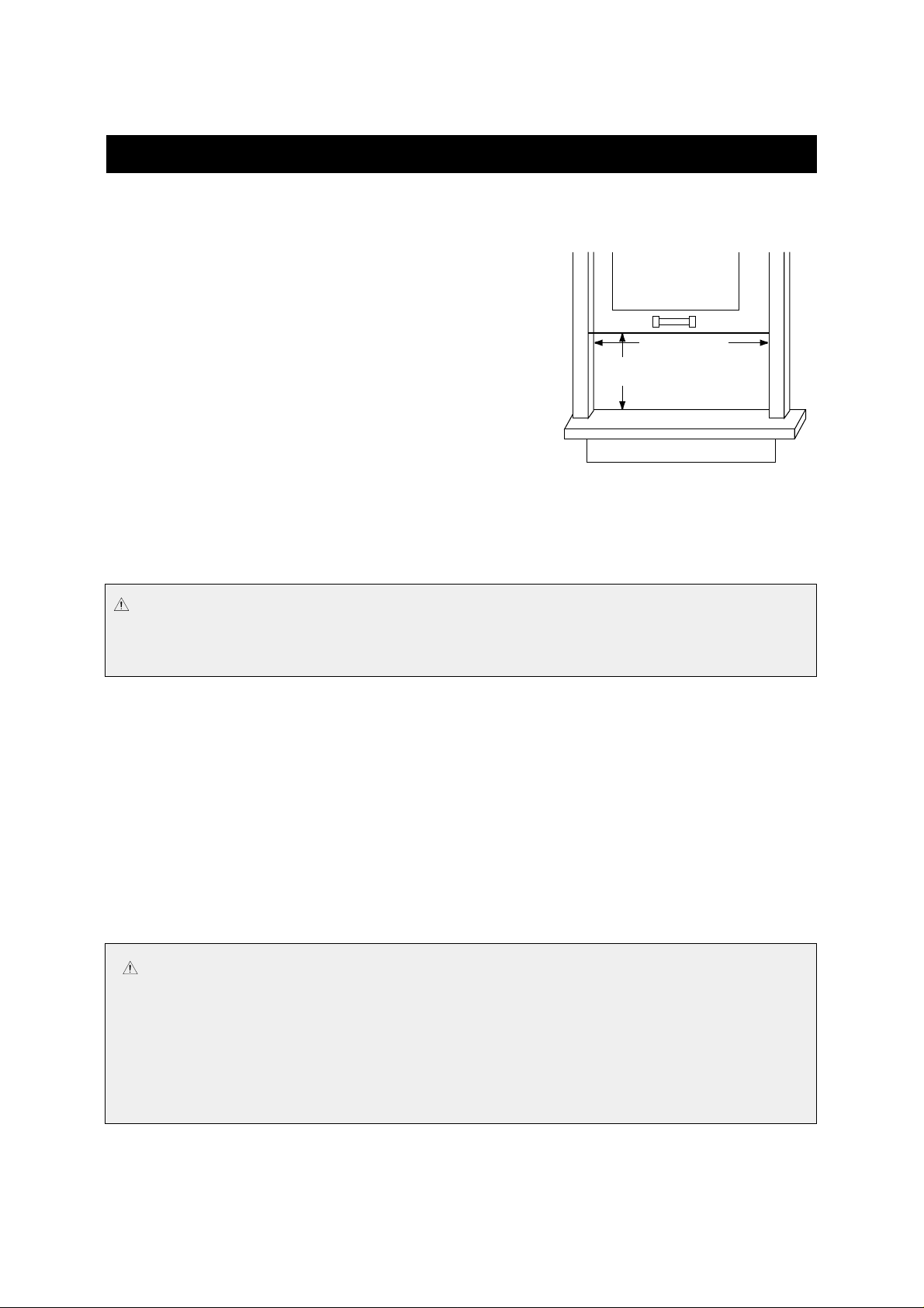
• WINDOW REQ UIREMENTS
These instructions are provided for a standard double hung window
or mobile home double hung window installation in windows 30.3
inch (770mm) to 43.3 inch (1100mm). The upper and lower sash
must open sufficiently to allow a clear vertical opening of 17.3 in
(440mm) from the bottom of the sash to the window sill.
Select a centrally located window on the side of the room that
receives the least direct sunlight. There should be no obstruction to
air flow either inside(i.e curtains) or outside (i.e fence, wall or
bushes).
Read this entire installation manual thoroughly before beginning the
installation.
Make sure you have the necessary tools and other materials for the
job. Study the illustrations in these instructions to become familiar with important details of the installation
process.
Read the Use & Care manual to become familiar with the operation of your room air conditioner.
After installing the unit, re-read these instructions to make sure you have completed each step and all parts are
fastened in place for a secure installation.
For best results, perform the installation procedure in the order given. Doing so will minimize the time required
to install the unit.
• BASIC T OOLS NEEDED
• SAFETY INSTRUCTIONS
IMPORTANT :
It is important, both for your personal safety and to avoid possible damage to your
home, that you observe the safety instructions that are given.
• Standard screwdriver
• Carpenter’s level
• Electric drill
• Phillips screwdriver
• 1/4” hex driver
• 1/8” drill bit
• Sharp knife
• Tape measure
27.5" To 36"
14.9" MIN
CAUTION
• The air conditioner shall be installed in accordance with the national wiring regulation.
1. Install an exclusive main power switch (main circuit breaker) or GFI (Ground Fault Interrupted)
switch.
2. Be sure to use grounded power source.
3. Power source for DWC-126R is 115V and DWA-146 is 208~230V.
4. Consumer must pay charges for wiring and installation.
17.3" MIN
30.3" To 43.3"

4
• SAFETY INSTRUCTIONS (CONTINUED)
The receptacle should be an individual branch circuit used only for this air conditioner. Be sure the electrical
service is adequate for the model air conditioner you have chosen. The complete electrical rating of your air
conditioner is stated on the name plate located at the unit’s side. Be sure the plug receptacle is close enough
for the power cord to reach it.
Your air conditioner must be plugged into a properly grounded and polarzied three prong receptacle. Do not
use an adapter plug. If the wall receptacle you intend to use will not accept a three-prong plug, or if you are not
sure the outlet is adequately grounded or protected by a fuse or circuit breaker, have a qualified electrician
install the proper oulet according to the National Electric Code and applicable local code.
• BEFORE INSTALLATION
Test Run Unit : Plug unit into proper power supply outlet.
Refer to operating instructions in this manual for comfortable living. Check all controls for correct
operation, then unplug unit.
Determine Correct Mounting procedure-Refer to Window Installation or Through the Wall Installation.
WARNING :
An extension cord should not be used with your air conditioner!
To minimize shock and fire hazards, proper grounding is important. For your safety and
protection,this air conditioner is equipped with a special three-prong grounding plug on the service cord.
WARNING :
Do not, under any circumstances, cut or remove the grounding prong on the plug. To do so will create a shock
hazard.
WARNING :
• Moving parts can cause personal injury. Be careful when test-running unit. Do not operate
unit with front grille removed .
• Be sure to use an exclusive power source.
• Contact service man for replacement of power cord.
5
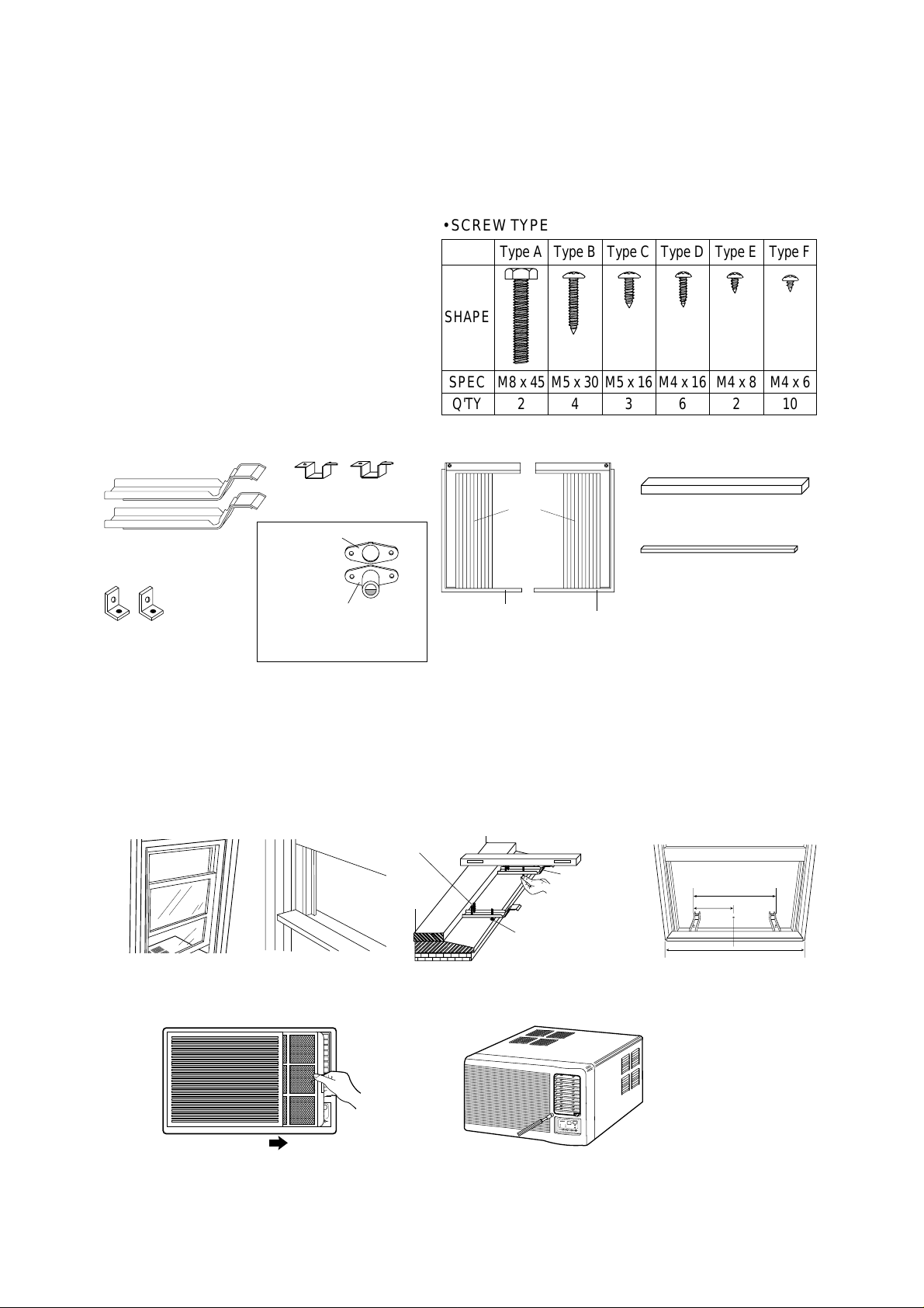
• Step 1 - Prepare Components For Installation
Parts for installation are as follows;
• Sill Bracket (2 pieces)
• Window Kit Left side (Frame ‘L+Shutter) - (1 piece)
• Window Kit Right side (Frame ‘R+Shutter) - (1 piece)
• Sash Bracket (2 pieces)
• DRAIN, DRAIN seal
• Frame Guide Lower - (2 pieces)
• Levelling Screw (Machine M8x45) - (2 pieces)
• 1 inch Screw (M5x30) - (4 pieces)
• 5/8 inch Screw (M5x16) - (3 pieces)
• 5/8 inch Screw (M4x16) - (6 pieces)
• DRAIN SCREW (M4x8) - (2 pieces)
• 1/4 inch Screw (M4x6) - (10 pieces)
• Window Seal A, B (2 pieces)
• Step 2 - Prepare Window For Installation
1. Inspect window track, sash and sill to be sure they are strong enough to hold an air conditioner.
2. Measure width between window frame to be sure instant mount will fit in the window. Instant mount models are
designed for Windows 30.3 inch (770mm) to 43.3 inch (1100mm) wide.
3. Mark the center of Window sill with pencil.
4. Insert Screws (Type A) into the sill bracket.
5. Attach Sill bracket to window sill using two Screws (Type B) by each bracket. The outside edge of window bracket
should be 13 inch (330mm) from center line.
6. Adjust Screw (Type A) so that Sill Bracket have a slight tilt by using carpenter's level meter.
• Step 3 - Preparation of Chassis
1. Pull the Air-filter out of the Front Grille.
2. Loosen screw which fasten Front Grille with screw drivers.
330mm
660mm
770~1100mm
Screw Type B
SILL
Screw Type A
SILL BRACKET
Room Air-conditioner
;
;
;
;
;
;
;
;
;
;
;
;
;
;
SHAPE
SPEC
Q'TY
Type A
M8 x 45
2
Type B
M5 x 30
4
Type C
M5 x 16
3
Type D
M4 x 16
6
Type E
M4 x 8
2
Type F
M4 x 6
10
• SCREW TYPE
R
o
o
m
A
i
r
c
o
n
d
i
t
i
o
n
e
r
Window
Shutter
(2 pieces)
Window Seal A (1 piece)
Window Seal B (1 piece)
Sill Bracket (2 pieces)
Window kit Frame
Left side (1 piece)
Window kit Frame
Right side (1 piece)
Sash Bracket
(2 pieces)
Frame Guide Lower
(2 pieces)
DRAIN Seal
DRAIN
SASH
✽ NOTE: Use Screw
(Type E) only
;;
;;
;;
;;
;;
;;
;;
;;;
;;;
;;;
;;;
;;;
;;;
;;;
6
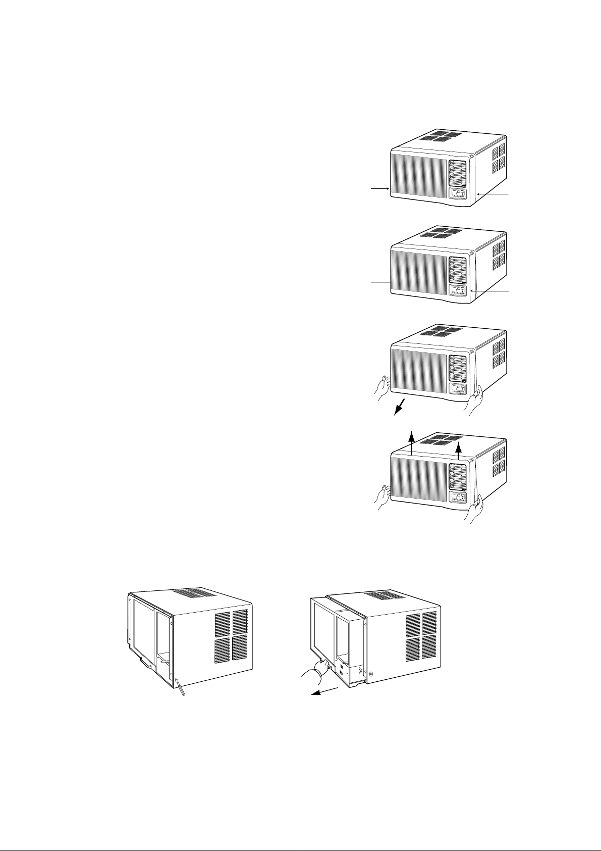
3. Disassemble Front Grille from Chassis.
– Front Grille and chassis are fixed with snap-fit.
1) Release right-lower snap-fit.
– Push the right lower side of chassis to the left, with pushing left side
of Front Grille to the right until the snap-fit is released.
2) Release left-lower snap-fit.
– Push the left-lower side of chassis to the right, with pushing right
side of Front Grille to the right until the snap-fit is released.
3) Pull lower side of the Front Grille until it is separated from the
chassis.
4) Push base side of the Front Grille to upper side until it is separated
from the chassis.
5) After front grille is removed, remove two screws located in both
side of chassis.
6) Grip the handle of base pan and pull out the unit from chassis.
❈
NOTICE:
Do not remove any Styrof oam because that is a part of the unit.
Push
Push
R
o
o
m
A
i
r
c
o
n
d
i
t
i
o
n
e
r
Push
Push
R
o
o
m
A
i
r
c
o
n
d
i
t
i
o
n
e
r
R
o
o
m
A
i
r
c
o
n
d
i
t
i
o
n
e
r
R
o
o
m
A
i
r
c
o
n
d
i
t
i
o
n
e
r
7
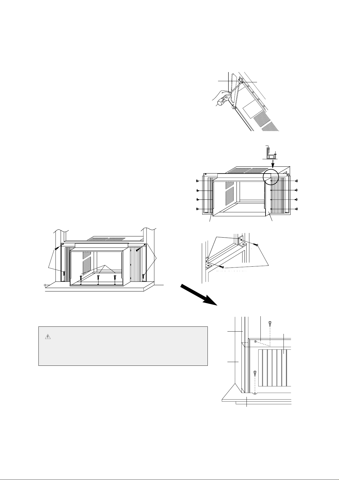
• Step 4 - Placing Chassis
1. Insert narrow side of ‘Frame Guide Lower’ to rectangle holes
located in bottom of chassis, and fasten it with Screw (Type F).
2. Insert Window Kit Frames to Top Guide and Lower Guide.
3. Fasten Shutter to side holes of Chassis with eight Screws (Type F).
4. Place the chassis on the window sill and align it with Sill Bracket
and sill with Lower Frame Guide and locate window sash to Top
Frame Guide. (check the end of chassis for about 1/2 inches
(12mm) distance below the level.)
5. Attach the Window seal B to Frame Guide Top.
6. Fasten Front Chassis Bracket to sill with three Screws
(Type C).
7. Fasten Sash Bracket with Screws (Type D) to top of
indoor window sash or directly into side of window
sash or directly into side of window frame. This will
prevent raising of the window from the outside. If you
have a hard wood or metal window frame, a 1/8 inch
pilot hole may be needed in order to drive the screws.
8. Attach the Window Seal A to window (see the picture
shown in step 8, page 8)
• Step 5 - Secure Window Shutter
To provide a proper seal, pull each expandable side Window Shutter
out and up until it is tight against the window frame. Using the hole in
the top and bottom of each Window Kit Frame as a guide, secure
Window Kit Frame in window sash and on the window sill.
Screw (Type F, both side)
FRAME
Guide Lower
Frame Guide Top
Window Seal B
Frame Guide Top
Window Seal B
TYPE 'D' SCREW
TYPE 'D' SCREW
Screw( Type F)
Screw
(Type C)
Screw
(Type D)
Screw
(Type D)
CAUTION Do not drill into window sash until window has
been inspected to make sure drilling or screw will
not damage any locking or lifting mechanism
located in the frame.
Screw( Type D)
SASH BRACKET
WINDOW
SASH
WINDOW
FRAME
INNER WINDOW SILL
WINDOW
KIT FRAME
Screw
(Type D)
Screw (Type D)
WINDOW
SHUTTER
 Loading...