

DAEWOO DTD-21H9 Service Manual

http : //svc.dwe.co.kr
Caution
: In this Manual, some parts can be changed for improving. their
performance without notice in the parts list. So, if you need the
latest parts information, please refer to PPL(Parts Price List)in
Service Information Center(http://svc.dwe.co.kr)
DAEWOO ELECTRONICS Corp.
Service Manual
Jan. 2005
COLOR TELEVISION
CHASSIS : CP-093F
MODEL : DTD-21H9
SM No :TCP093FEF0

CP-093F Service Manual
CONTENTS
1. MAIN FEATURES 2
1.1 SPECIFICATIONS 2
1.1.1 GENERAL 2
1.1.2 EURO-SCART 1(21Pin) 3
1.1.3 CHANNEL/FREQUENCY TABLE 4
2. SAFETY INSTRUCTION 7
3. ALIGNMENT INSTRUCTIONS 8
3.1 MICROCONTROLLER CONFIGURATION:SERVICE MODE 8
3.2 SERVICE MODE NADVIGATION 8
3.3 MICROCONTROLLER CONFIGURATION:OPTION BITS 8
3.4 OPTION 1 9
3.5 OPTION 2 9
3.6 NVM default setting 10
4. TV SET ALIGNMENT 12
4.1 G2 ALIGNMENT 12
4.2 WHITE BALANCE 12
4.3 FOCUS 12
4.4 VERTICAL GEOMETRY 12
4.5 HORIZONTAL PICTURE CENTRING 12
4.6 EAST/WEST CORRECTION 12
4.7 AGC 13
5 IC DESCRIPTION 14
5.1 UOC
///
Series 14
5.1.1 IC MARKING AND VERSION 14
5.1.2 BLOCK DIAGRAM 15
5.1.3 PINNING 16
5.1.4 FEATURES 17
5.2 TDA8944J STEREO AUDIO AMPLIFIER 22
5.2.1 FEATURES 23
5.3 TDA8357J VERTICAL AMPLIFIER 25
5.3.1 TDA8357J 25
5.4 TDA6107AJE 28
5.4.1 Features 28
5.4.2 Pin description 28
5.5 24WC16-16KB EEPROM 29
5.6 STR-F6756/4 30
5..6.1 Functions of Each Terminal 30
5..6.2 Block Diagram(Connection diagram) 30
5..6.3 CONTROL PART - ELECTRICAL CHARACTERISTICS 33
6. SPECIFICATIONS 34
7. SERVICE PARTS LIST 37
8. EXPLODED VIEW 51
9. SCHEMATIC DIAGRAM 55
1. MAIN FEATURES
2
1.1 SPECIFICATIONS
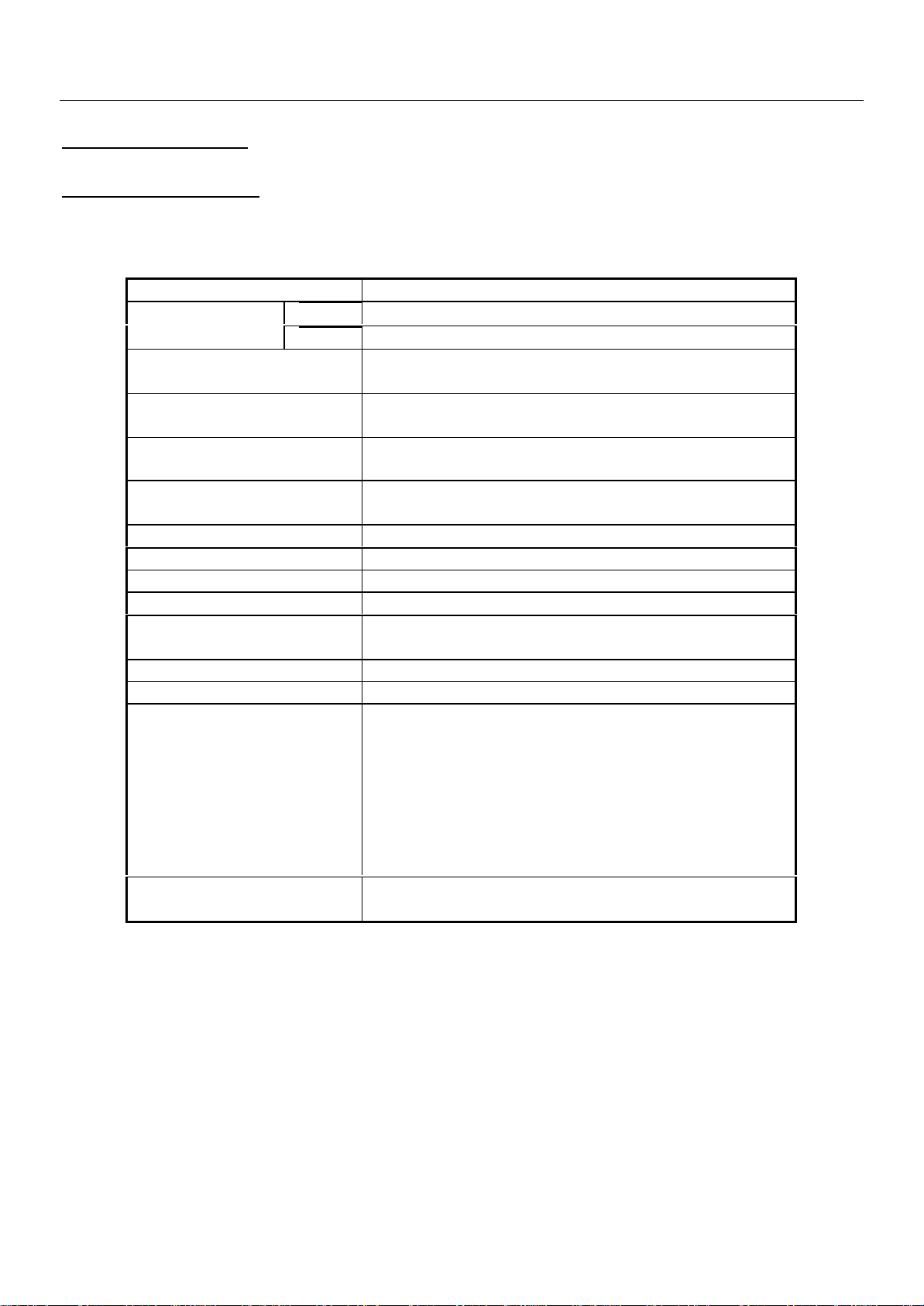
1.1.1 GENERAL
TV standard PAL - SECAM B/G D/K, PAL I/I, SECAM L/L’
Sound system NICAM B/G, I, D/K, L,
Power
consumption 21” : 74W
Sound Output
Power 20” : 3W x 2 (at 60% mod, 10%THD)
Speaker
Teletext system 10 pages memory FASTEXT (FLOF or TOP)
Aerial input 75 ohm unbalanced
Channel coverage Off-air channels, S-cable channels and hyperband
Tuning system frequency synthesiser tuning system
Visual screen size
Channel indication On Screen Display
Program Selection 100 programmes
Aux. terminal - EURO-SCART : Audio / Video In and Out, R/G/B
CP-093F Service Manual
Tuner PAL, SECAMColour system
AV PAL, SECAM, PAL 60, NTSC M, NTSC 4.43
FM 2Carrier B/G, D/K
21” : 5W 8 ohm x2 is not connected)
21” : 51cm
In, Slow and Fast switching.
Remote Control
Unit
- Headphone jack on front of cabinet
(21”)
- AV2 : Video and Audio L/R out, Headphone jack
at side of cabinet.
R-52C03
CP-093F Service Manual
3
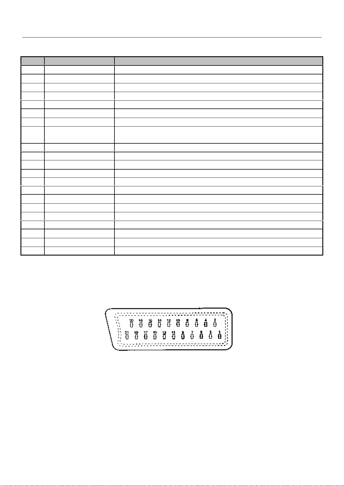
1.1.2 EURO-SCART 1 (21 Pin)
Pin Signal Description Matching value
1 Audio Output Right 0.5 Vrms, Impedance < 1 kΩ, ( RF 54% Mod )
2 Audio Input Right 0.5 Vrms, Impedance > 10 kΩ
3 Audio Output Left 0.5 Vrms, Impedance < 1 kΩ, ( RF 54% Mod )
4 Audio Earth
5 Blue Earth
6 Audio Input Left 0.5 Vrms, Impedance > 10 kΩ
7 Blue Input 0.7 Vpp ±0.1V, Impedance 75Ω
8 Slow Switching TV : 0 to 2V, AV 16/9 : 4.5 to 7V, AV 4/3 : 9.5 to 12V , Impedance
> 10 kΩ
9 Green Earth
10 N.C.
11 Green Input 0.7 Vpp ± 0.1V, Impedance 75Ω
12 N.C.
13 Red Earth
14 Blanking Earth
15 Red Input
16 Fast Switching 0 to 0.4V : Logic “0”, 1 to 3V : Logic “1”, Impedance 75Ω
17 Video Out Earth
18 Video In Earth
19 Video Output
20 Video Input 1 Vpp ± 3dB, Impedance 75Ω
21 Common Earth
0.7 Vpp ± 0.1V, Impedance 75Ω
1 Vpp ± 3dB, Impedance 75Ω

CP-093F Service Manual
4
1.2 CHANNEL/FREQUENCY TABLE
CHANNEL EUROPE CCIR FRANCE GB(IRELAND) EAST OIRT
C01
C02
C03
C04
C05
C06
C07
C08
C09
C10
C11
C12
C13
C14
C15
C16
C17
C18
C19
C20
C21
C22
C23
C24
C25
C26
C27
C28
C29
C30
C31
C32
C33
C34
C35
C36
C37
C38
C39
C40
C41
C42
C43
C44
C45
46.25 - 45.75 49.75
48.25 55.75 (L') 53.75 59.25
55.25 60.5 (L') 61.75 77.25
62.25 63.75 (L') 175.25 85.25
175.25 176.00 183.25 93.25
182.25 184.00 191.25 175.25
189.25 192.00 199.25 183.25
196.25 200.00 207.25 191.25
203.25 208.00 215.25 199.25
210.25 216.00 223.25 207.25
217.25 189.25 (LUX) 231.25 215.25
224.25 69.25 (L') 239.25 223.25
53.75 76.25 (L') 247.25 -
- 83.25 (L') 49.75 -
82.25 90.25 57.75 -
- 97.25 65.75 -
183.75 - 77.75 -
192.25 - 85.75 -
201.25 - - -
- - - -
471.25 471.25 471.25 471.25
479.25 479.25 479.25 479.25
487.25 487.25 487.25 487.25
495.25 495.25 495.25 495.25
503.25 503.25 503.25 503.25
511.25 511.25 511.25 511.25
519.25 519.25 519.25 519.25
527.25 527.25 527.25 527.25
535.25 535.25 535.25 535.25
543.25 543.25 543.25 543.25
551.25 551.25 551.25 551.25
559.25 559.25 559.25 559.25
567.25 567.25 567.25 567.25
575.25 575.25 575.25 575.25
583.25 583.25 583.25 583.25
591.25 591.25 591.25 591.25
599.25 599.25 599.25 599.25
607.25 607.25 607.25 607.25
615.25 615.25 615.25 615.25
623.25 623.25 623.25 623.25
631.25 631.25 631.25 631.25
639.25 639.25 639.25 639.25
647.25 647.25 647.25 647.25
655.25 655.25 655.25 655.25
663.25 663.25 663.25 663.25

CP-093/F Service Manual
5
C46
C47
C48
C49
C50
C51
C52
C53
C54
C55
C56
C57
C58
C59
C60
C61
C62
C63
C64
C65
C66
C67
C68
C69
C70
C71
C72
C73
C74
C75
C76
C77
S01
S02
S03
S04
S05
S06
S07
S08
S09
S10
S11
S12
S13
S14
S15
S16
S17
671.25 671.25 671.25 671.25
679.25 679.25 679.25 679.25
687.25 687.25 687.25 687.25
695.25 695.25 695.25 695.25
703.25 703.25 703.25 703.25
711.25 711.25 711.25 711.25
719.25 719.25 719.25 719.25
727.25 727.25 727.25 727.25
735.25 735.25 735.25 735.25
743.25 743.25 743.25 743.25
751.25 751.25 751.25 751.25
759.25 759.25 759.25 759.25
767.25 767.25 767.25 767.25
775.25 775.25 775.25 775.25
783.25 783.25 783.25 783.25
791.25 791.25 791.25 791.25
799.25 799.25 799.25 799.25
807.25 807.25 807.25 807.25
815.25 815.25 815.25 815.25
823.25 823.25 823.25 823.25
831.25 831.25 831.25 831.25
839.25 839.25 839.25 839.25
847.25 847.25 847.25 847.25
855.25 855.25 855.25 855.25
863.25 863.25 863.25 863.25
69.25 - - -
76.25 - - -
83.25 - - -
90.25 - - -
97.25 - - -
59.25 - - -
93.25 - - -
105.25 104.75 103.25 105.25
112.25 116.75 111.25 112.25
119.25 128.75 119.25 119.25
126.25 140.75 127.25 126.25
133.25 152.75 135.25 133.25
140.25 164.75 143.25 140.25
147.25 176.75 151.25 147.25
154.25 188.75 159.25 154.25
161.25 200.75 167.25 161.25
168.25 212.75 - 168.25
231.25 224.75 - 231.25
238.25 236.75 - 238.25
245.25 248.75 255.25 245.25
252.25 260.75 263.25 252.25
259.25 272.75 271.25 259.25
266.25 284.75 279.25 266.25
273.25 296.75 287.25 273.25

CP-093F Service Manual
6
S18
S19
S20
S21
S22
S23
S24
S25
S26
S27
S28
S29
S30
S31
S32
S33
S34
S35
S36
S37
S38
S39
S40
S41
280.25 136.00 295.25 280.25
287.25 160.00 303.25 287.25
294.25 - - 294.25
303.25 303.25 - 303.25
311.25 311.25 311.25 311.25
319.25 319.25 319.25 319.25
327.25 327.25 327.25 327.25
335.25 335.25 335.25 335.25
343.25 343.25 343.25 343.25
351.25 351.25 351.25 351.25
359.25 359.25 359.25 359.25
367.25 367.25 367.25 367.25
375.25 375.25 375.25 375.25
383.25 383.25 383.25 383.25
391.25 391.25 391.25 391.25
399.25 399.25 399.25 399.25
407.25 407.25 407.25 407.25
415.25 415.25 415.25 415.25
423.25 423.25 423.25 423.25
431.25 431.25 431.25 431.25
439.25 439.25 439.25 439.25
447.25 447.25 447.25 447.25
455.25 455.25 455.25 455.25
463.25 463.25 463.25 463.25

CP-093F Service Manual
7
2. SAFETY INSTRUCTION
WARNING: Only competent service personnel may carry out work involving the testing or repair
of this equipment.
X-RAY RADIATION PRECAUTION
1. Excessive high voltage can produce potentially hazardous X-RAY RADIATION. To avoid
such hazards, the high voltage must not exceed the specified limit. The nominal value of the high
voltage of this receiver is 25-26 KV (20 ”-21”) or 26 KV (25” - 28 ”) at max beam current. The high
voltage must not, under any circumstances, exceed 27.5 KV (20 ”), 29KV (21”), 29.5 KV (25") or
30 KV (28"). Each time a receiver requires servicing, the high voltage should be checked. It is
important to use an accurate and reliable high voltage meter.
2. The only source of X-RAY Radiation in this TV receiver is the picture tube. For continued
X-RAY RADIATION protection, the replacement tube must be exactly the same type tube as
specified in the parts list.
SAFETY PRECAUTION
Potentials of high voltage are present when this receiver is operating. Operation of the receiver
outside the cabinet or with the back board removed involves a shock hazard from the receiver.
Servicing should not be attempted by anyone who is not thoroughly familiar with the precautions
necessary when working on high voltage equipment.
Discharge the high potential of the picture tube before handling the tube. The picture tube is
highly evacuated and if broken, glass fragments will be violently expelled.
If any Fuse in this TV receiver is blown, replace it with the FUSE specified in the Replacement
Parts List.
When replacing a high wattage resistor (metal oxide film resistor) in the circuit board, keep the
resistor 10 mm away from circuit board.
Keep wires away from high voltage or high temperature components.
This receiver must operate under AC 230 volts, 50 Hz. NEVER connect to a DC supply or any
other voltage or frequency.
PRODUCT SAFETY NOTICE
Many electrical and mechanical parts in this equipment have special safety-related
characteristics. These characteristics are often passed unnoticed by a visual inspection and the
X-RAY RADIATION protection afforded by them cannot necessarily be obtained by using
replacement components rated for higher voltage, wattage, etc. Replacement parts which have
these special safety characteristics are identified in this manual and its supplements, electrical
components having such features are identified by designated symbol on the parts list. Before
replacing any of these components, read the parts list in this manual carefully. The use of
substitutes replacement parts which do not have the same safety characteristics as specified in
the parts list may create X-RAY Radiation.
CP-093F Service Manual
8
3. ALIGNMENT INSTRUCTIONS
3.1 MICROCONTROLLER CONFIGURATION : SERVICE MODE
To switch the TV set into service mode please see instruction below.
1 - Select PR. number 91
2 - Adjust sharpness to minimum and exit all menus.
3 – Within 2 seconds press the key sequence : RED - GREEN - menu
The software version is displayed beside the word Service, e.g. “SERVICE VER 00.05”.
To exit SERVICE menu press menu key or Std By key.
3.2 SERVICE MODE NAVIGATION
Pr Up/Down remote keys : cycle through the service items available.
Vol -/+ remote keys : Dec./Increment the values within range – Cycle trough option bits.
OK key : Toggle bits in option byte
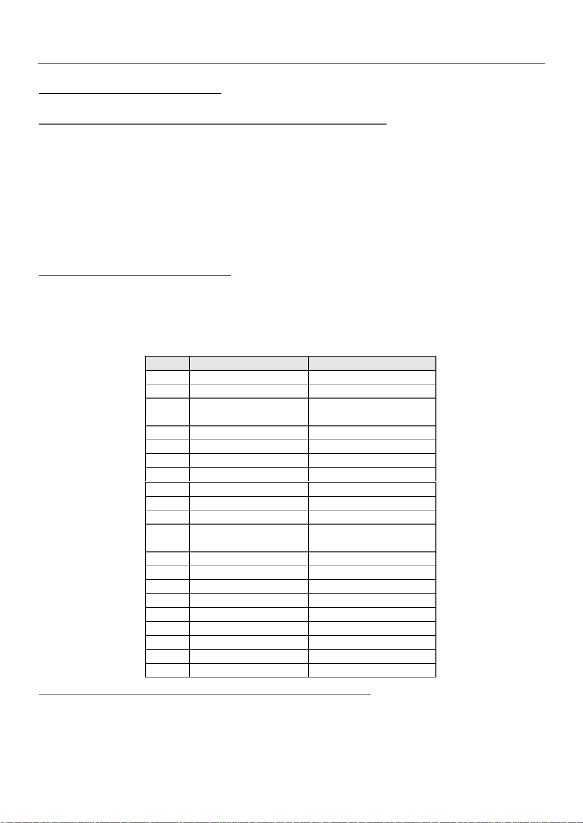
Order Item Default setting
1 HOR CEN
2 RED GAIN
3 GRN GAIN
4 BLUE GAIN
5 RED BIAS
6 GRN BIAS
7 AGC LEVEL
8 G2 – SCREEN
9 OPTION1
10 OPTION2
11 AVL
12 PARABOLA
13 HOR WIDTH
14 CORNER T
15 CORNER B
16 HOR. PARAL
17 V. LINEAR
18 V. SLOPE
19 EW TRAPEZ
20 S CORRECT
21 VERT CENT
22 VERT SIZE
3.3 MICROCONTROLLER CONFIGURATION : OPTION BITS
There are two option bytes available (16 bits in all). These option bits are available from Service
mode. First find the OPTION1 or OPTION2 control, and then use the Volume PLUS/MINUS
buttons on the remote control keypad to locate the bits, and OK key to toggle them. The table
below shows the two option bytes available;
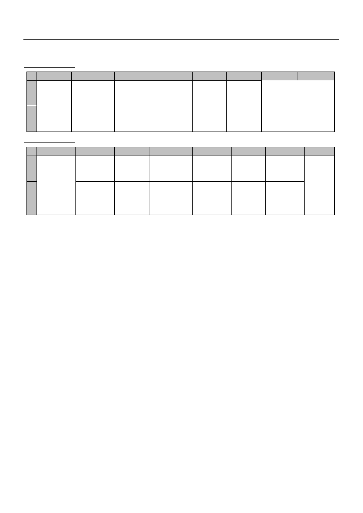
3.4 OPTION 1
9
B7 B6 B5 B4 B3 B2 B1 B0
TOP
1
Teletext
OFF
TOP
Teletext
0
ON
3.5 OPTION 2
B7 B6 B5 B4 B3 B2 B1 B0
1
Fixed to
‘0’
0
FASTEXT
(FLOF)
OFF
FASTEXT
(FLOF) ON
JVC
remote
control
Daewoo
Remote
control
TUBE
4:3
TUBE
16:9
AVL
control
OFF
AVL
control
ON
VAI bit set
to 1 in
SECAM L
VAI bit set
to 0 in
SECAM L
PICTURE
TILT ON
PICTURE
TILT OFF
Dolby
Virtual
OFF
Dolby
Virtual
ON
14”
(AV2
OFF)
21”
(AV2
ON)
SVHS3
disable
SVHS3
enable
Full
ATSS
Basic
ATSS
CP-093F Service Manual
TUNER OPTIONS
00 = Philips
01 = Not used
10 = Alps
11 = Parstnic (DW)
Double
Window
Enabled
Double
Window
Disabled
n.u.
Must
be set
to 1 for
future
compa
tibility

CP-093F Service Manual
10
3.6 NVM default setting
The purpose of this message, when you change a virgin EEPROM, is to allow to modify
the NVM DATA to desired values.
1 - Introduction :
The NVM default values are fixed for the user, but for flexibility in service, these data are stored
in NVM and can be changed when the TV set is in a special mode call "NVM EDITOR". This
mode can only be access from "FACTORY" mode.
2 - Entering into "FACTORY" mode.
To switch the TV set into FACTORY mode, use the factory remote control, and press on “SVC”
key. The factory menu will appear on the screen, showing “FACTORY” , plus other relevant
information like software version and date.
WARNING : When in "FACTORY" mode you should not press any key other than the keys
described in the procedure below. Unwanted key stroke could misadjust the TV set.
3 - Entering into "NVM EDITOR" mode.
To switch the TV set into NVM EDITOR mode, use the user remote control, and press on
“ON/ENTER” key. The NVM EDITOR window will appear on the screen. This mode allow you to
access all data stored in NVM. The current NVM address is given in column "ADDR." in both
DECimal and HEXadecimal format. The column DATA gives the value contained at selected
address in both DECimal and HEXadecimal format.
4 - Navigation in "NVM EDITOR" mode.
Use Program Up/Dwn keys to select the desired address. Use Volume Up/Down keys to change
the data at selected address. You must press " OK/ENTER" key to store value after modification.
The data can be adjusted between 0 and 63.
5 - Exit "NVM EDITOR" mode.
To switch the TV set back into FACTORY mode, use the user remote control, and press on
“MENU” key.
The factory menu will appear on the screen, showing “FACTORY”.
6 - Exit "FACTORY" mode.
To exit "FACTORY" mode, use the factory remote control, and press on “SVC” key.
The factory menu will disappear from the screen.
CP-093F Service Manual
11
NVM DATA CHANGE LIST
No Register Name Address Default 14H9 21H9
1 OCP_THRESHOLD 0x58F 0x91 <- <2 DCXO 0x590 0x4E <- <3 AVLLEV 0x621 0x5 <- <4 TELETEXT - Brightness 0x642 0x19 <- <5 OSD - Brightness 0x644 0x7 <- <6 Nor1_Bright 0x64A 0x23 <- <7 Nor1_contrast 0x64B 0x2E <- <8 Nor1_Colour 0x64C 0x1C <- <9 Nor1_Sharpness 0x64D 0x23 <- <-
10 Nor1_Tint 0x64E 0x20 0x1F 0x1F
11 Nor2_Bright 0x653 0x28 <- <12 Nor2_Contrast 0x654 0x13 <- <13 Nor2_Colour 0x655 0x19 <- <-
14 Nor2_Sharpness 0x656 0x1B <- <15 Nor2_Tint 0x657 0x20 0x1F 0x1F
16 V - Linearity 0x667 0x2A 0x22 0x27
17 Peak White Level 0x671 0x1 <- <18 Soft Clipping Level 0x672 0x5 0x7 0x7
19 PresetGainRGB 0x673 0x2A 0x1 0x7
20 PresetGainRGB 0x674 0x2A 0x1 0x7
(hex)
21 PresetGainRGB 0x675 0x2A 0x1 0x7
22 Cathode_Drive 0x67B 0x1 <- <23 RPA 0x680 0x1 0x2 0x2
24 Black Stretch 0x682 0x1 0x2 0x2
25 BSD 0x683 0x1 0x0 0x0
26 AAS 0x684 0x1 0x0 0x0
27 BCS 0x685 0x1 <- <28 Y_delay_PAL_BG 0x686 0x5 <- <29 Y_delay_SECAM_BG 0x687 0x8 <- <-
30 Y_delay_PAL_DK 0x688 0x5 <- <31 Y_delay_SCM_DK 0x689 0x5 <- <32 Y_delay_PAL_I 0x68A 0x7 <- <33 Y_delay_SECAM 0x68B 0x5 <- <34 Y_delay_SECAM-L 0x68C 0x8 <- <35 Y_delay_AV 0x68D 0xA <- <36 G2_Bright 0x68E 0x1A <- <37 G2_Contrast 0x68F 0x42 <- <-
CP-093F Service Manual
12
4. TV SET ALIGNMENT
4.1 G2 ALIGNMENT
- Tune a colour bar pattern.
- Find the “G2 – SCREEN ” item in service mode.
- Adjust screen volume (on FBT) to bring the cursor to central position (Green).
4.2 WHITE BALANCE
- Select a dark picture and adjust RED BIAS and GRN BIAS to the desired colour temperature.
- Select a bright picture and adjust RED, GRN and BLUE GAIN to the desired colour temperature.
4.3 FOCUS
Adjust the Focus volume (on FBT) to have the best resolution on screen.
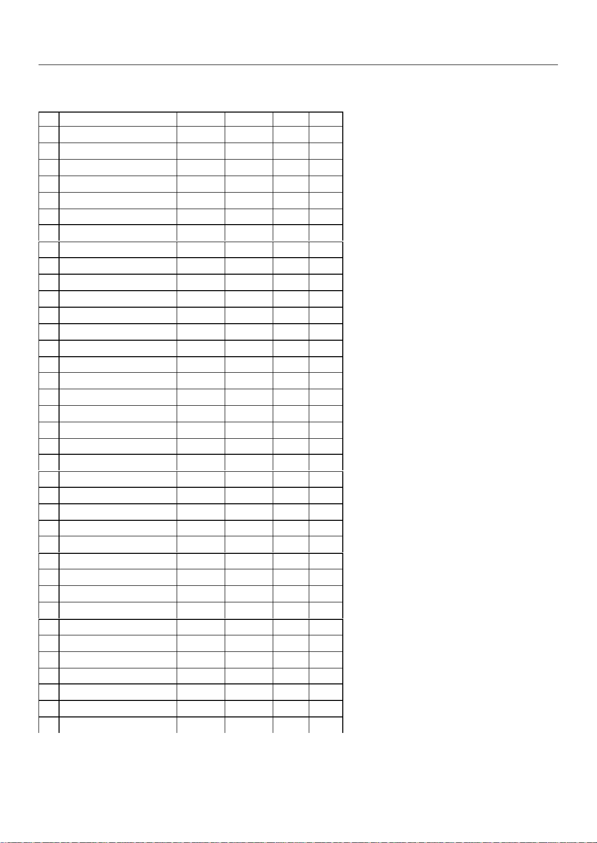
4.4 VERTICAL GEOMETRY
Adjust V. LINEAR (linearity), S CORRECT (S. Correction), VERT SIZE (Vertical amplitude),
VERT CENT (vertical centring) to compensate for vertical distortion.
4.5 HORIZONTAL PICTURE CENTRING
Adjust HOR CEN (Horizontal centre) to have the picture in the centre of the screen.
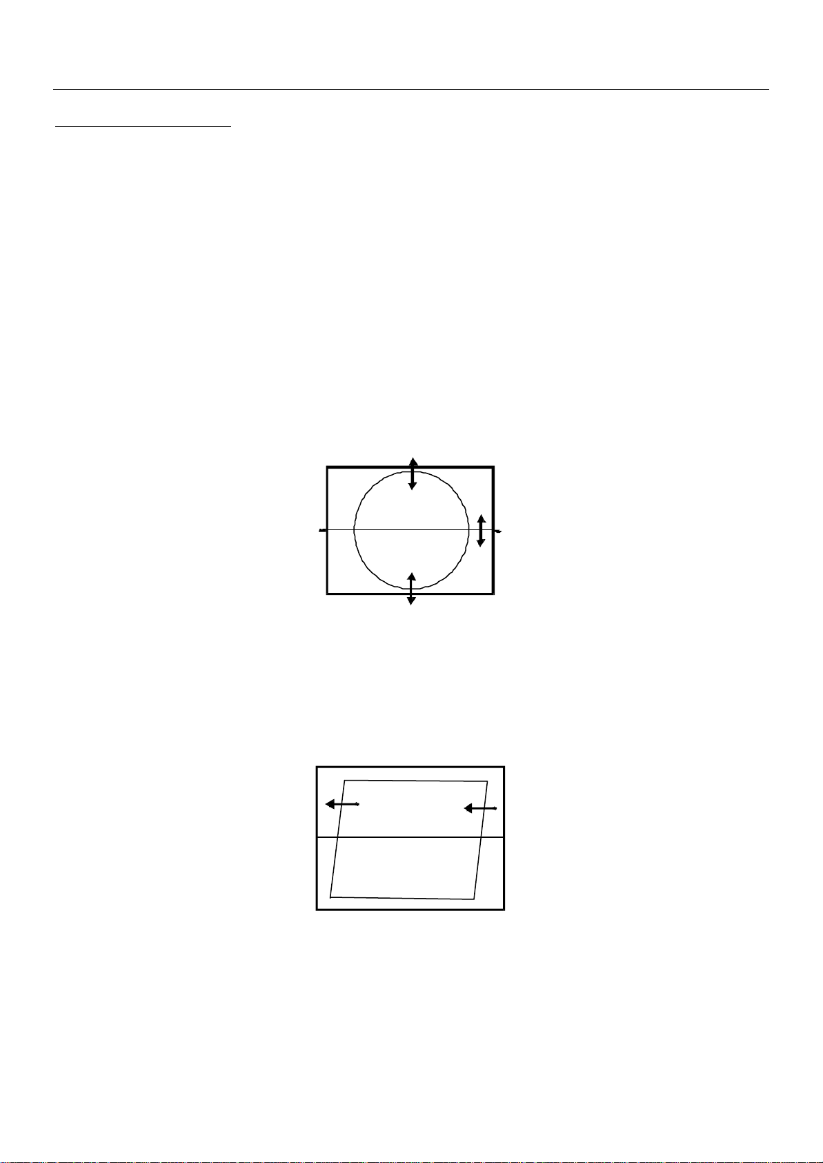
4.6 EAST / WEST CORRECTION
Adjust the PARABOLA, HOR WIDTH, CORNER, HOR PARAL, EW TRAPEZ, to compensate for
geometrical distortion.
HOR PARAL
HOR WIDTH
13
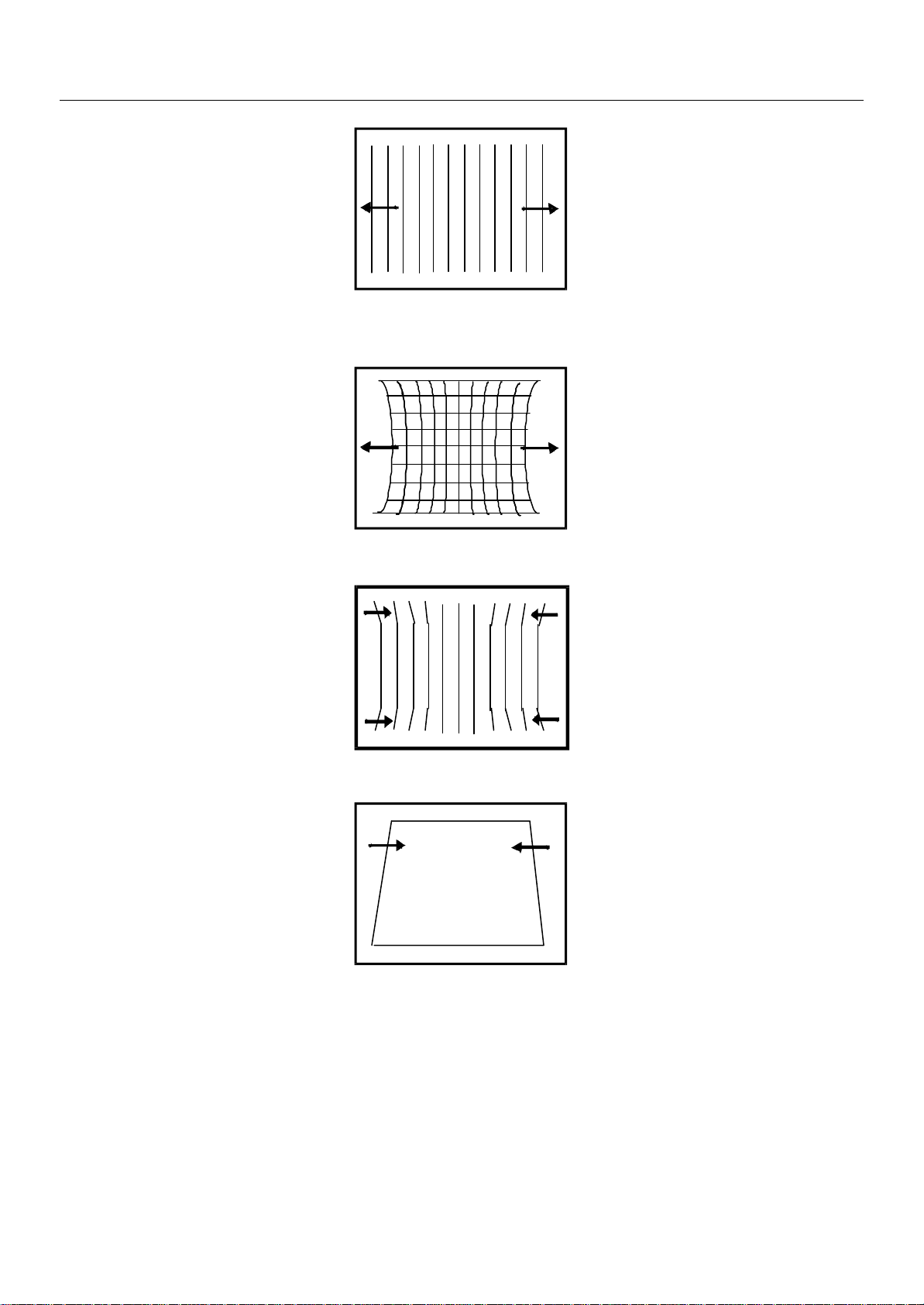
adjust for 93% overscan.
CP-093F Service Manual
PARABOLA
CORNER B & CORNER T
EW TRAPEZ
4.7 AGC
- Make sure option bits are correct for the tuner fitted on the chassis (See above how to change
option bits).
- Adjust the antenna signal level at 62 dBµV
- Tune a colour bar pattern.
- Find the “AGC” item in service mode.
- Press the key “OK ” on the remote keypad and wait until AGC level stabilise to the optimum
value.
 Loading...