

DAEWOO DSA-240L-R Service Manual

Manual de Servicio
Acondicionador de Aire Tipo Split
Modelo: DSA-240L-R

CONTENTS
1. Specifications..........................................................................................................2
2. Outline and Dimensions.........................................................................................4
3. Operation.................................................................................................................6
4. Wiring Diagram.....................................................................................................17
5. Refrigerant Cycle..................................................................................................20
6. Control Block Diagram.........................................................................................21
7. Electric Circuit Diagram........................................................................................23
8. Trouble Shooting...................................................................................................26
9. Key Components of Electronic Circuit.................................................................48
10. Disassembly Instructions .....................................................................................51
1) Indoor Unit........................................................................................................51
2) Outdoor Unit.....................................................................................................52
3) Exploded Diagram (Indoor Unit)......................................................................53
4) Exploded Diagram (Outdoor Unit)...................................................................56
5) Control Box Assembly......................................................................................60
Contents
2
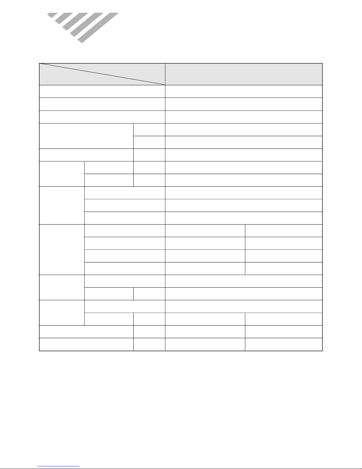
1. SPECIFIC A TIONS
MODEL
DSA-240L-R
ITEM
Function Cooling
Class T
Power AC 220V/ 60Hz
Capacity W 7,030
Btu/h 24,000
Dehumidification l/h 3.2
Running Current A 11.7
Power Input W 2,500
Type Recipro
Model AWG5530EXC
Capacitor 45µF/ 400VAC
Division Indoor Unit Outdoor Unit
Type Cross flow fan Propeller fan
Capacitor 2µF 400VAC 5µF 400VAC
Motor Model Number IC9430DWKG7A 05ME986DERC
Control Capillary
Charge Q'ty g 2,100
Type Flare
OD
(Liquid/Suction)
in(mm) 3/8 (9.52) 5/8 (15.9)
Dimensions (W x H x D) mm 1080 x 298 x 200 872 x 675 x 325
Net Weight kg 14.7 64
Electrical
Data
Compressor
Fan
Motor
Refrigerant
(R-22)
Connection
* DSA-240L-R
3
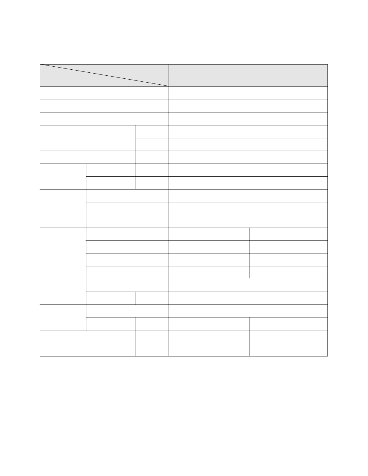
MODEL
DSA-240LH-R
ITEM
Function Cooling & Heating
Class T
Power AC 220V/ 60Hz
Capacity W 7,030
Btu/h 24,000
Dehumidification l/h 2.67
Running Current A 11.5 / 11.8
Power Input W 2,500 / 2,550
Type Recipro
Model AWG5530EXC
Capacitor 45µF/ 400VAC
Division Indoor Unit Outdoor Unit
Type Cross flow fan Propeller fan
Capacitor 2µF 400VAC 5µF 400VAC
Motor Model Number IC9430DWKG7A 05ME986DERC
Control Capillary
Charge Q'ty g 2,200
Type Flare
OD
(Liquid/Suction)
in(mm) 3/8 (9.52) 5/8 (15.9)
Dimensions (W x H x D) mm 1080 x 298 x 200 872 x 675 x 325
Net Weight kg 14.7 64
Electrical
Data
Compressor
Fan
Motor
Refrigerant
(R-22)
Connection
* DSA-240LH-R
4
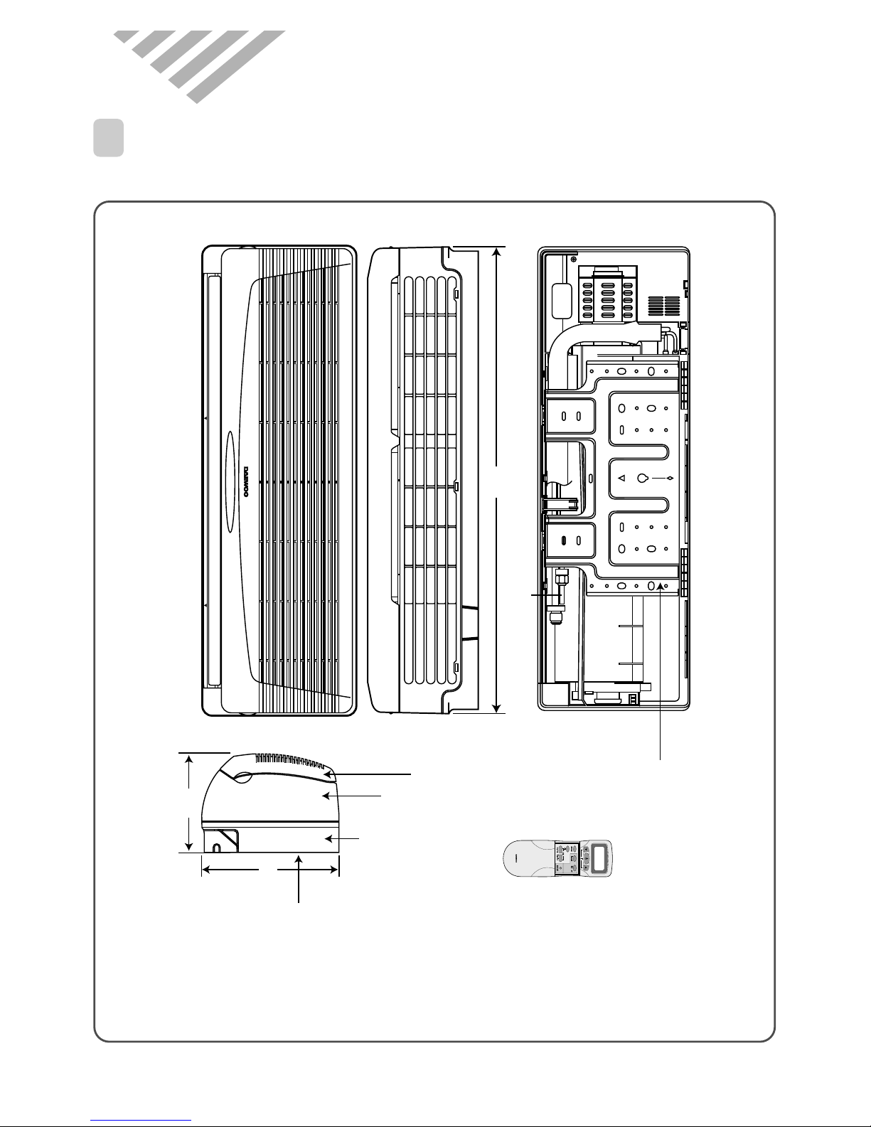
750
Plate Mounting
REMOCON
Connecting Pipe
Grille Insert
174
245
REMOTE CONTROLLER
Frame Grille
Body
Plate Mounting
2. OUTLINE AND DIMENSIONS
1
INDOOR UNIT
* DSA-240L-R/LH-R
5
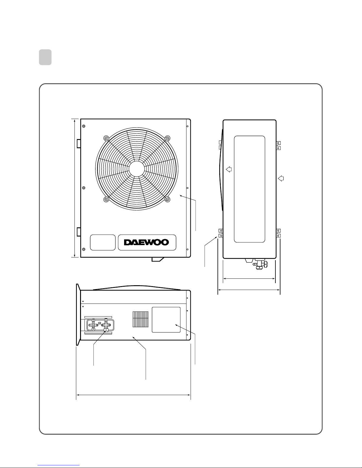
Inlet
380
699
323
foot
Service valve
873
Cabinet front
Service Cover
Cabinet Side
* DSA-240L-R/LH-R
2
OUTDOOR UNIT
6
1
PARTS OF NAME AND FUNCTION
3. OPERA TION
* DSA-240L-R/LH-R
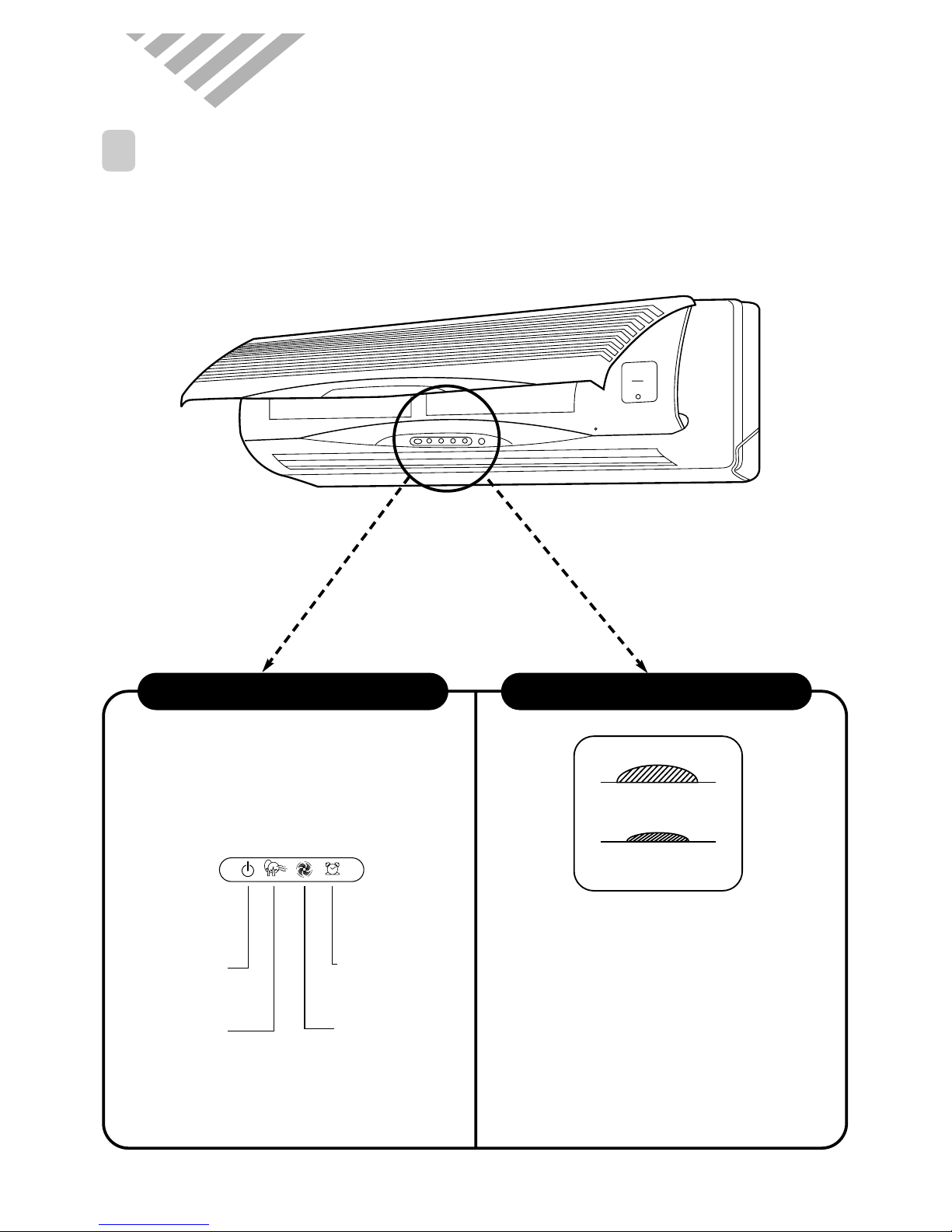
■
Remote Control Signal Receiver
This place is the part to receive the signal if it
receive the signal, you can hear the signal “beep.
“beep, beep .”
■
There is a switch panel at inside of
Front Panel. At the time of operating,
open the Front Panel.
Emergency switch can be used when the remote
controller is lost or Testing.
Remote switch is usually used by remote
controller.
Indoor Unit Display Switch Panel
Timer (Yellow)
Lights-on during the time
of reservation mode.
Quick (Red)
Lights-on during the time
of Quick Mode.
ON (Red)
Lights-on
during the operation
Air clean (Green)
Lights-on
during the operation
EMERGENCY
REMOCON
REMOCON
EMERGENCY
7
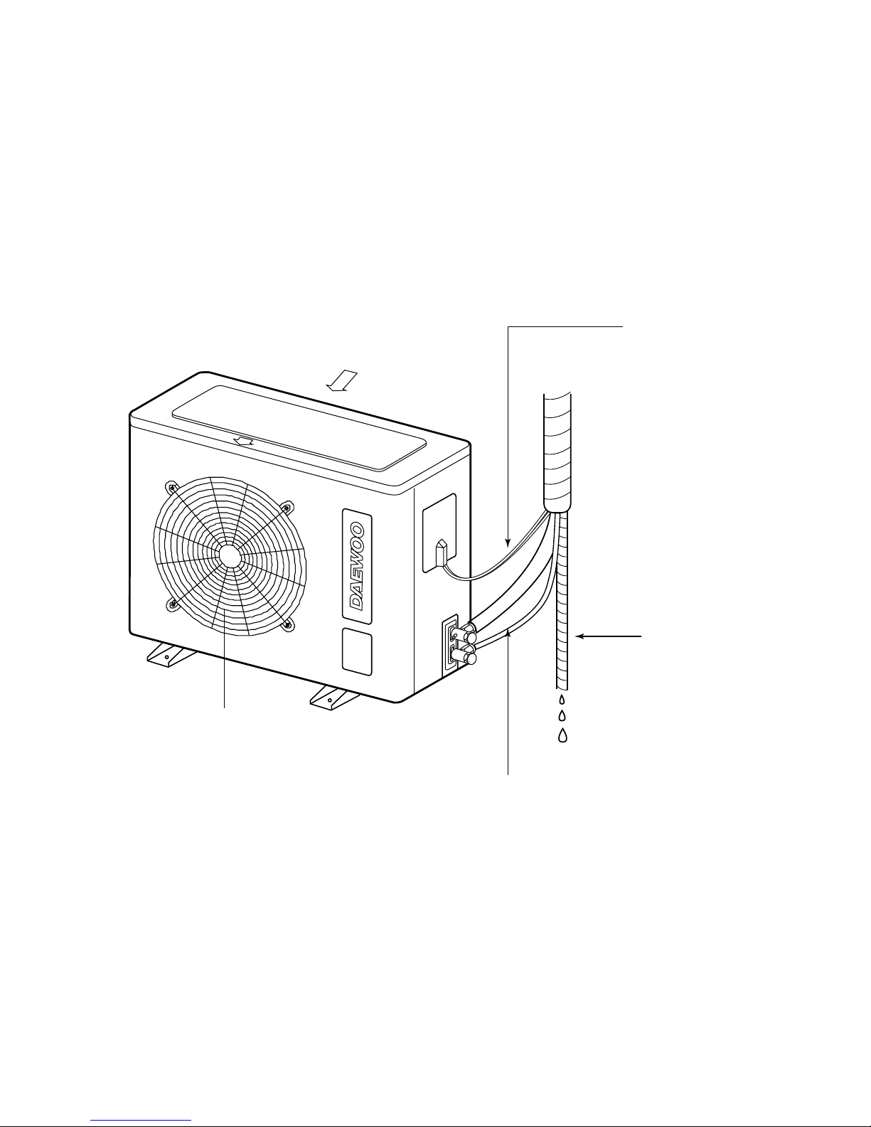
* DSA-240L-R/LH-R
Air Inlet
Air Outlet
Connection Pipe
Connection wire
Drain Hose
8
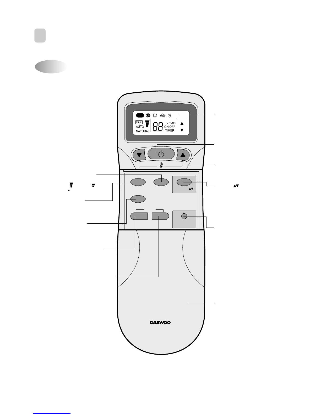
Name of Each Button
2
REMOTE CONTROLLER
* DSA-240L-R
MODE
SLEEP
ON/OFF
TIMER
ENTER/
CANCEL
FAN SPEED
TURBO/MILD
Display
Displays information
pertaining to unit.
TURBO/MILD
Press to be colder the unit.
TIMER ENTER/CANCEL Button
Press to enter a timer setting or
to cancel timer setting
TIMER ON/OFF Button
Press to set the unit of or on time.
(0.5, 1, 1.5, 2, 2.5, 3, 4, 5, 6, 8,
10, 12, 16, 20, 24hr)
MODE Button
Press to cycle through the modes
(Auto/Quick/Cooling/Fan/Dry)
SLEEP Button
Press to set the unit for
the sleep mode.
FAN DIR.
FAN DIR. Button
Press to select up/down
direction for fan.
ON/OFF Button
Press to turn the unit
on or off.
TEMPERATURE Buttons
Press to raise or lower
the desired temperature.
FAN SPEED Button
Press to select the fan speed
(High " ", Middle " ",
Low " ").
COVER
Slide down to access most
of the remote buttons.
Slide down further to
access the battery
compartment.
AUTO
REMOTE CONTROLLER
9
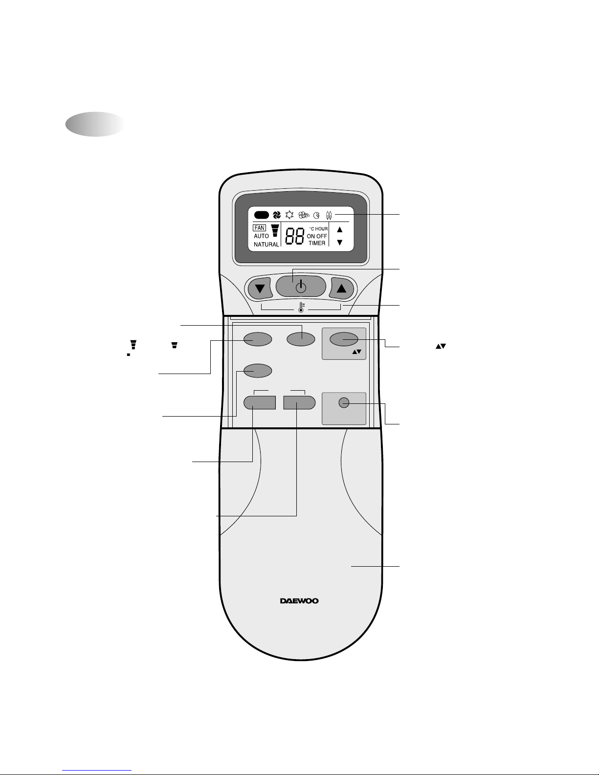
Name of Each Button
* DSA-240LH-R
MODE
SLEEP
ON/OFF
TIMER
ENTER/
CANCEL
FAN SPEED
TURBO/MILD
Display
Displays information
pertaining to unit.
TURBO/MILD
Press to be colder the unit.
TIMER ENTER/CANCEL Button
Press to enter a timer setting or
to cancel timer setting
TIMER ON/OFF Button
Press to set the unit of or on time.
(0.5, 1, 1.5, 2, 2.5, 3, 4, 5, 6, 8,
10, 12, 16, 20, 24hr)
MODE Button
Press to cycle through the modes
(Auto/Quick/Cooling/Fan/Dry)
SLEEP Button
Press to set the unit for
the sleep mode.
FAN DIR.
FAN DIR. Button
Press to select up/down
direction for fan.
ON/OFF Button
Press to turn the unit
on or off.
TEMPERATURE Buttons
Press to raise or lower
the desired temperature.
FAN SPEED Button
Press to select the fan speed
(High " ", Middle " ",
Low " ").
COVER
Slide down to access most
of the remote buttons.
Slide down further to
access the battery
compartment.
AUTO
REMOTE CONTROLLER
10
R epla cin g Ba tte r ies
3
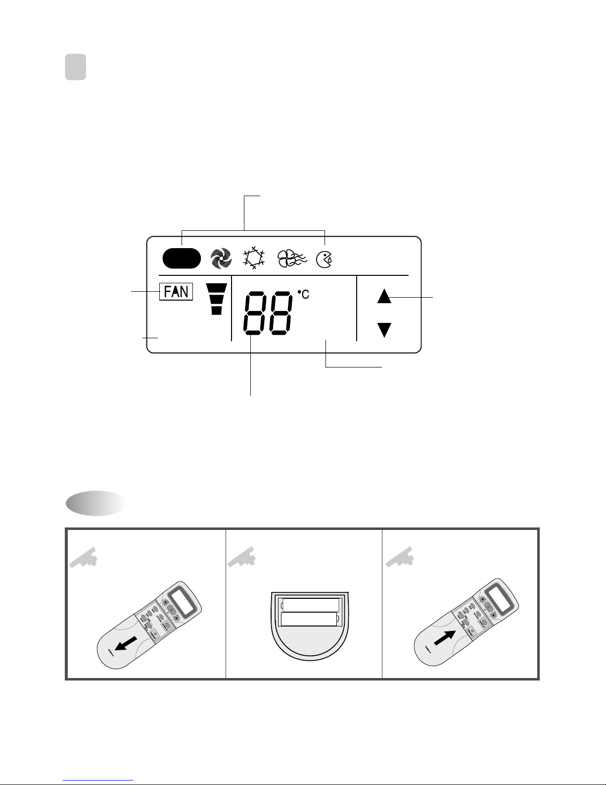
R EM O TE CO N TRO LLER DISP LAY
Open the cover after
pressing the arrow
direction and pulling out.
Put the drycell by +. direction.
Close the cover after
pushing into arrow
direction.
1
2
3
R
E
M
O
T
E
C
O
N
T
R
O
L
L
E
R
+Ð
+Ð
R
E
M
O
T
E
C
O
N
T
R
O
L
L
E
R
* DSA -2 4 0 L-R
MODE Indicators (Auto/Quick/Cool/Fan/Dehumidifier/Heat)
Lights to indicate the mode selected.
TIMER Indicators (Include sleep)
Lights to indicate the timer function mode.
TEMPERATURE & RESERVATION TIME lndicator
Lights to indicate the temperature or time.
FAN DIRECTION Indicators
Lights to indicate the
fan direction.
NATURAL Indicator
Lights to indicate the
speeds simulating a loreeze.
FAN Indicators
Lights to indicate
the fan speed.
AUTO
AUTO
NATURAL
ON OFF
TIMER
HOUR
11
R epla cin g Ba tte r ies
Open the cover after
pressing the arrow
direction and pulling out.
Put the drycell by +, direction.
Close the cover after
pushing into arrow
direction.
1
2
3
R
E
M
O
T
E
C
O
N
T
R
O
L
L
E
R
+Ð
+Ð
R
E
M
O
T
E
C
O
N
T
R
O
L
L
E
R
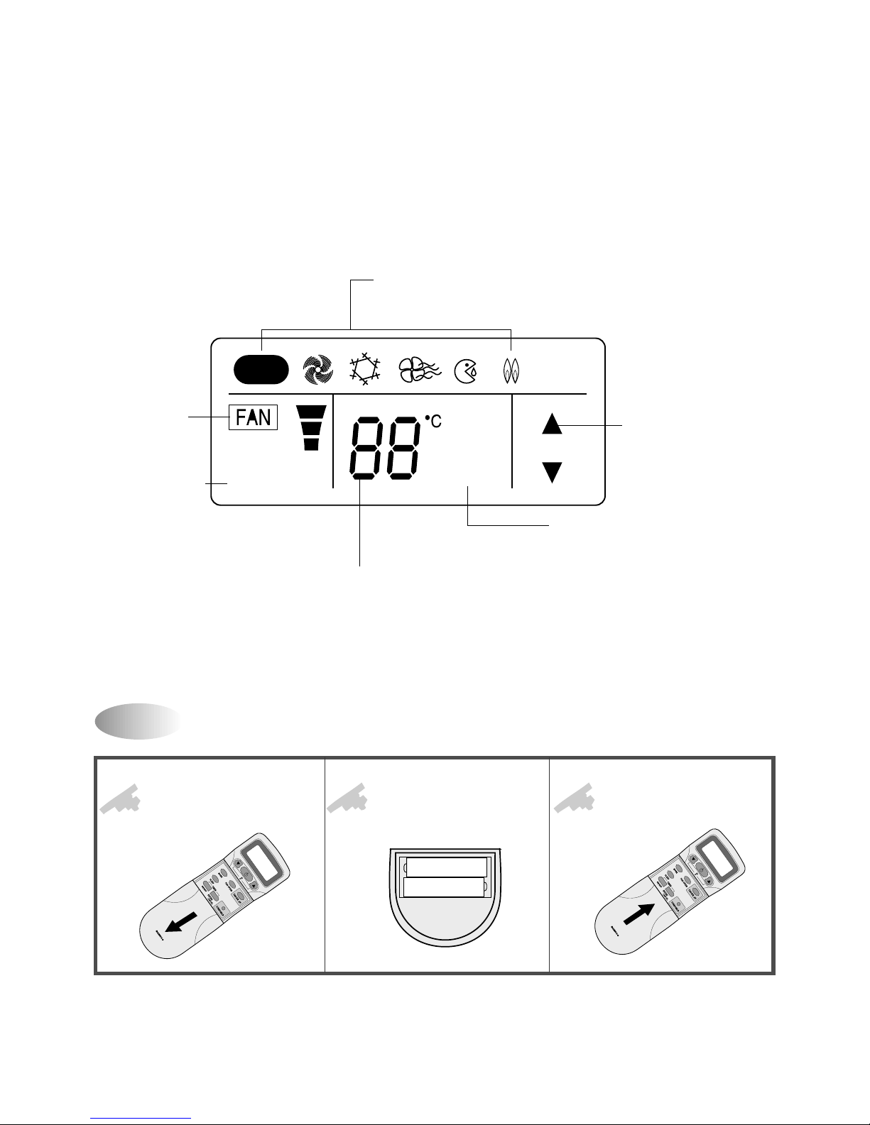
* DSA -2 4 0 LH -R
MODE Indicators (Auto/Quick/Cool/Fan/Dehumidifier/Heat)
Lights to indicate the mode selected.
TIMER Indicators (Include sleep)
Lights to indicate the timer function mode.
TEMPERATURE & RESERVATION TIME lndicator
Lights to indicate the temperature or time.
FAN DIRECTION Indicators
Lights to indicate the
fan direction.
NATURAL Indicator
Lights to indicate the
speeds simulating a loreeze.
FAN Indicators
Lights to indicate
the fan speed.
AUTO
AUTO
NATURAL
ON OFF
TIMER
HOUR
12
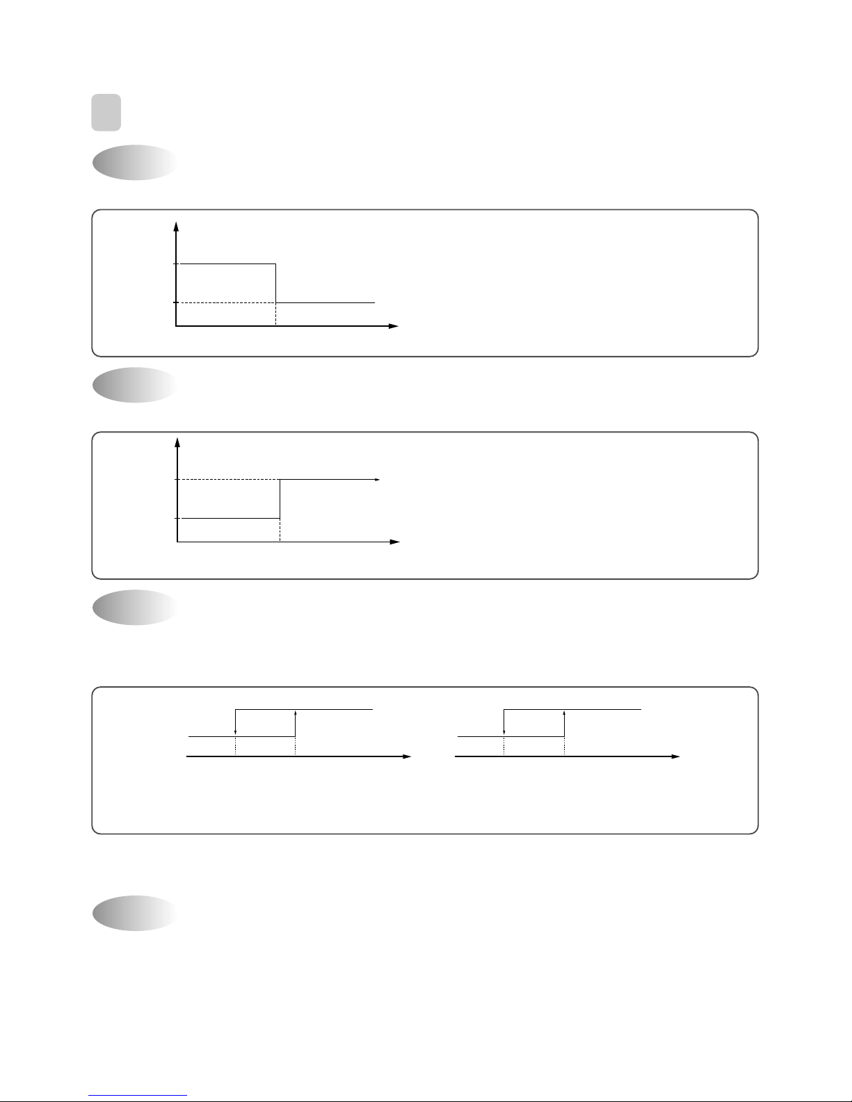
If you set time in OFF-Timer Mode, the unit will stop at the set time.
If you set time in ON-Timer Mode, the unit will run at the set time.
(1) Range of setting temperature: 18~32°C
(2) Setting temperature: Operating temperature of compressor
If the Indoor Unit Display receive the signal of Remote Controller , y ou can hear the signal "beep –" or "beep ,
beep".
(1) In the case of receiving ON/OFF signal-"beep" "beep"
(2) And so on-"beep"
OFF-Timer
4
DESCRIPTION OF FUNCTIONS
Unit ON
Unit OFF
SET Time
HOUR
ON
OFF
ON-Timer
Unit ON
Unit OFF
SET Time
HOUR
ON
OFF
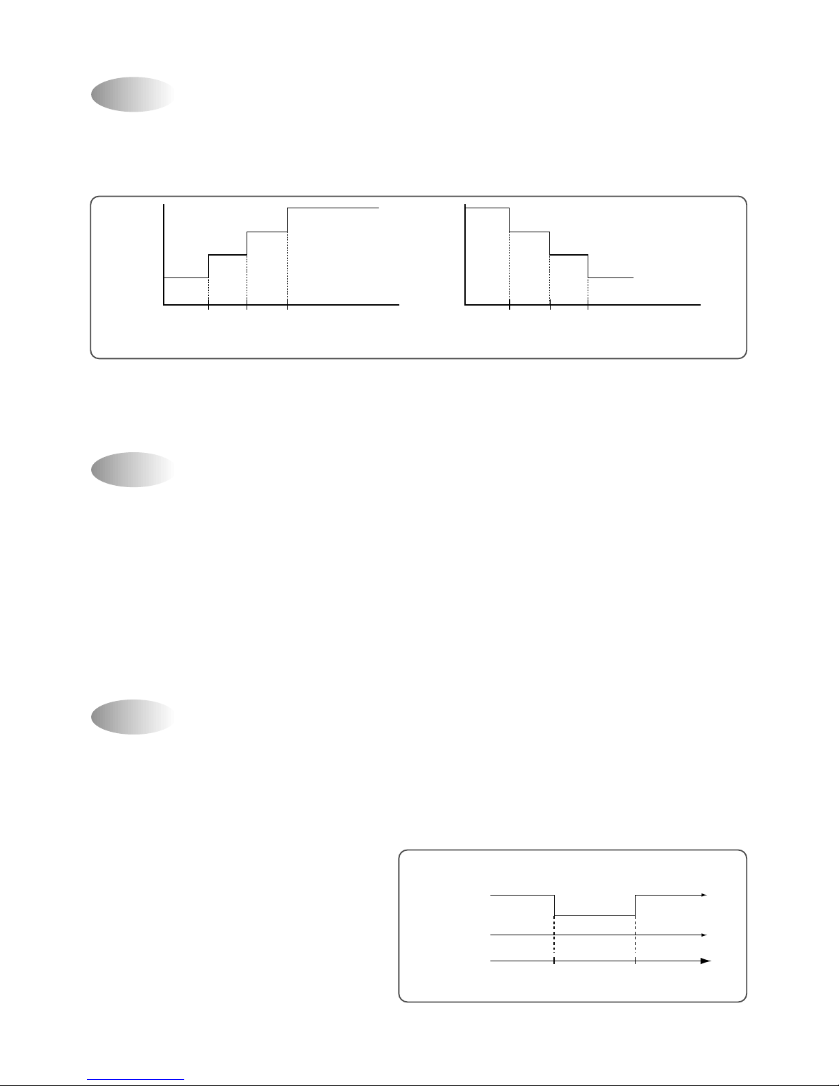
Control of Room Temperature
Buzzer
COMP (ON)
*RT: ROOM TEMPERATURE
DT: DESIRED TEMPERATURE
COMP (OFF)
-1°C0°C
(COOLING)
(RT-DT)
COMP (OFF)
COMP (ON)
-1°C0°C
HEATING
(RT-DT)
+1°C +2°C
(DSA-240LH-R)
13
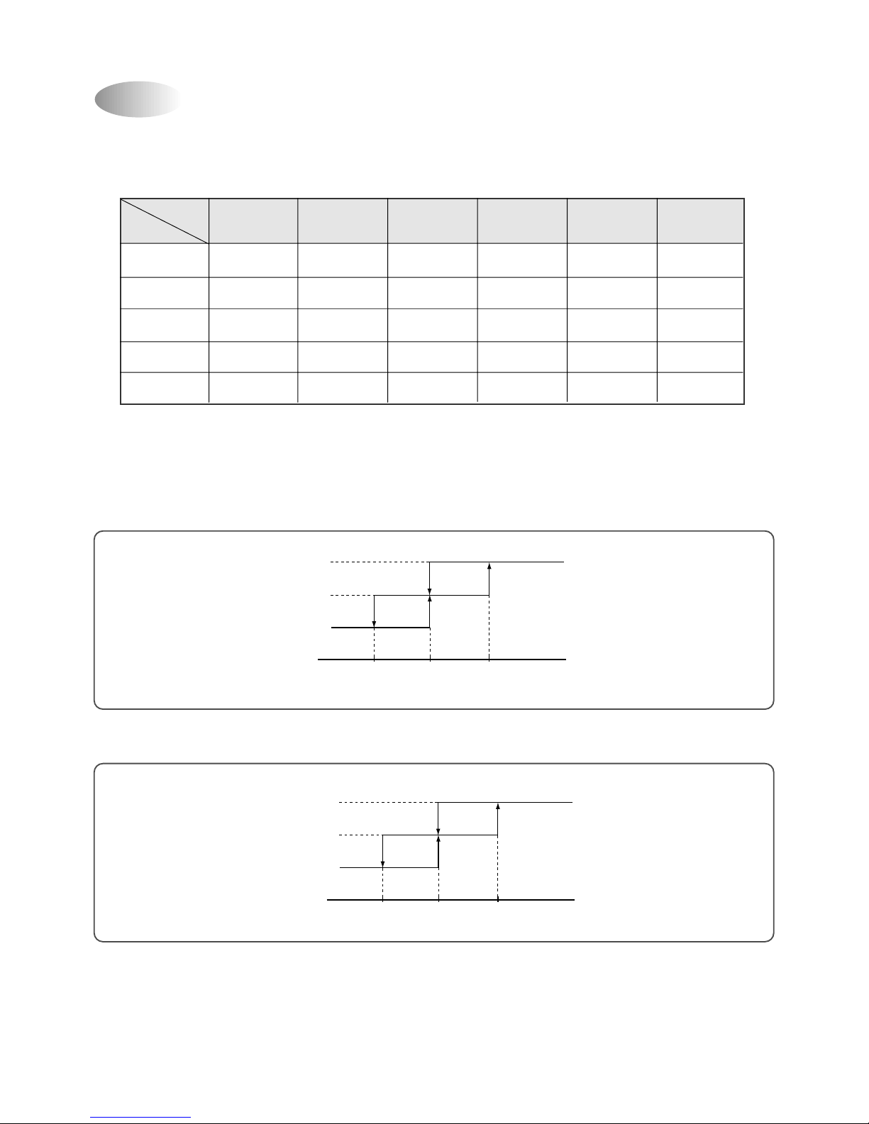
Fan Speed (Indoor Unit)
(1) Motor speed (High speed, midium speed, low speed).
(2) Remote controller setting fan speed. (Auto , L, M, H, Natural)
(3) Relation of operating mode between fan speed. (legned: X-no relation)
(4) Automatic Operation
If the unit is set in 'AUT O' mode, the unit operates automatically according to the room temperature to k eep the
room temperature comfortable.
0°C
L
M
H
1°C2°C
(RT-DT)
(D.T)
0°C
L
M
H
1°C2°C
(DT-RT)
(COOLING)
(HEATING)
DSA-240LH-R
FAN ONLY COOL
DEHUMI-
AUTO QUICK
HEAT
DIFICATION
(DSA-240LH-R)
H HHLHHH
M MMLMHM
L LLLLHL
Auto Auto L Auto H Auto
Natural Natural Natural L Natural H Natural
14
(1) When the remote controller is lost, damaged or the battery is discharged, the Emergency operation can be
used to run the unit.
(2) The setting conditions of Emergency operation are as follows.
Operation mode: Quick
Preset temperature:18C: Cooling, 32C: Heating)
Fan speed: High
You cannot operate with remote controller.
(1) When you are going to sleep, select sleep switch and the unit controls the room to the desired temperature.
(The unit will automatically turn off after 4 hour)
(2) For changing the temperature.
(3) To cancel sleep mode, press the SLEEP button again or press the MODE button once.: the SLEEP
indicator will disappear in the display.
S le ep M od e
Em e r g ency O p era tion
0 0.5 1.0 HOUR
(COOLING CYCLE)
DT
+0.5 C
+0.5 C
+0.5 C
0 0.5 1.0 HOUR
(HEATING CYCLE) DSA-240LH
DT
- 0.5 C
- 0.5 C
- 0.5 C
Fros t P re ve ntio n o f In d oo r U nit
When the unit operates at low ambient temperature, frost may appear on the Evaporator. When the indoor coil
temperature is lower than -1 C at the end of 10 minutes of continuous compressor operation from the star t, the
microcomputer of the unit stops the compressor to protect the unit from the frost. The control procedure for
indoor coil freeze protection.
1) The compressor and outdoor fan turn off.
2) Indoor fan operates according to user set speed.
3) The normal operation returns when the indoor coil
temperature is higher than 7 C or equal to 7 C.
-1 C+7 C
Compressor and
Outdoor Fan
ON ON
OFF
Indoor Fan
Set speed
(Indoor coil temperature)
(HEATING CYCLE) DSA-240LH-R
*
*
*
15
Auto Mode
(1) In Auto Mode
After the indoor fan is operated f or 20 seconds in the Auto Mode the unit will operate automatically b y selecting
operating Mode according to the room temperature
3 min. Time Delay of Compressor
In normal operation, there is a time delay of three minutes between turn off and turning back on.
(In the initial power up, the time dela y is 30 seconds)
ROOM TEMPERATURE
DT-2°C
>
RT
DT-2°C
≤
RT ≤DT+3°C
DT+3°C
<
RT
OPERA TING MODE
DSA-240L-R Cooling
DSA-240LH-R Heating
Dehumidifier
Cooling
FLAP POSITION
Cooling Position
Heating Position
Cooling Position
Cooling Position
(RT: Room temperature)
16
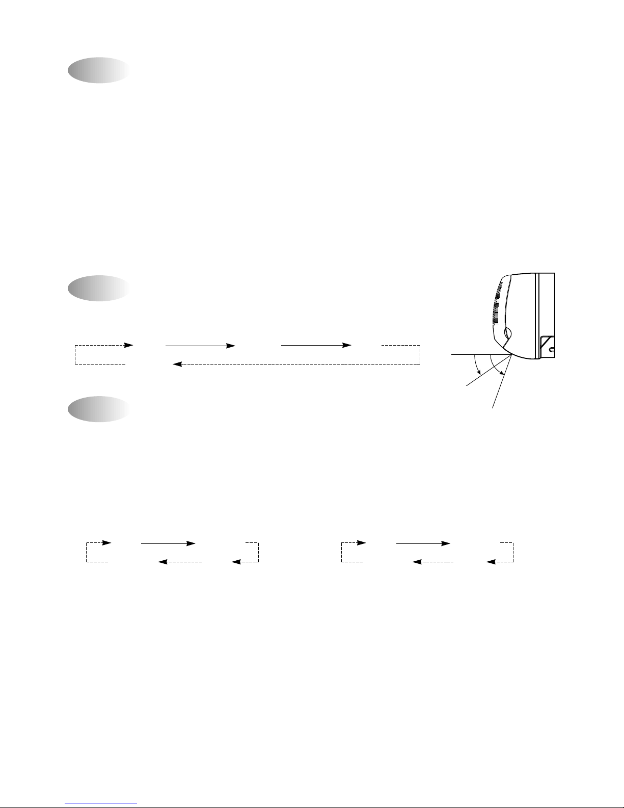
1) Cooling Mode
When the room temperature is higher than 22C
Fan Speed: High speed
Air discharge direction: Fixed
Set temperature: 18C (Fixed)
The air discharge direction procedure is below
Fixed Up/Down
Up/Down Fixed
The option is LEFT/RIGHT direction.
1) Heating Mode
When the room temperature is lower than 22C
Fan Speed: Super high speed
Air discharge direction: Fixed
Set temperature: 18C (Fixed)
The air discharge direction procedure is below
Fixed Up/Down
Up/Down Fixed
The option is LEFT/RIGHT direction.
Deh um idifica tion M od e
A ir Dis ch a r g e Dir ection(on ly re m o co n o p er a tion)
Q u ick M od e(Po w e r f ul Co o lin g & H ea tin g)
The air discharge direction procedure is below.
Fixed UP/Down Fixed
Up/Down
Desired temperature < Room temperature
Outdoor Fan, Compressor : ON
Indoor Fan : Low speed
Desired temperature Room temperature
Compressor : 3 min/ON, 5 min/OFF
Fan Speed : low speed
Room temperature 18 C
Compressor : OFF
Fan speed : Low speed
COOLING POSITION
HEATING POSITION
<
=
17
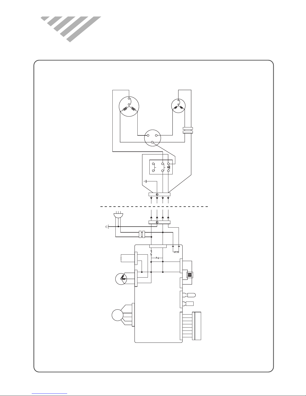
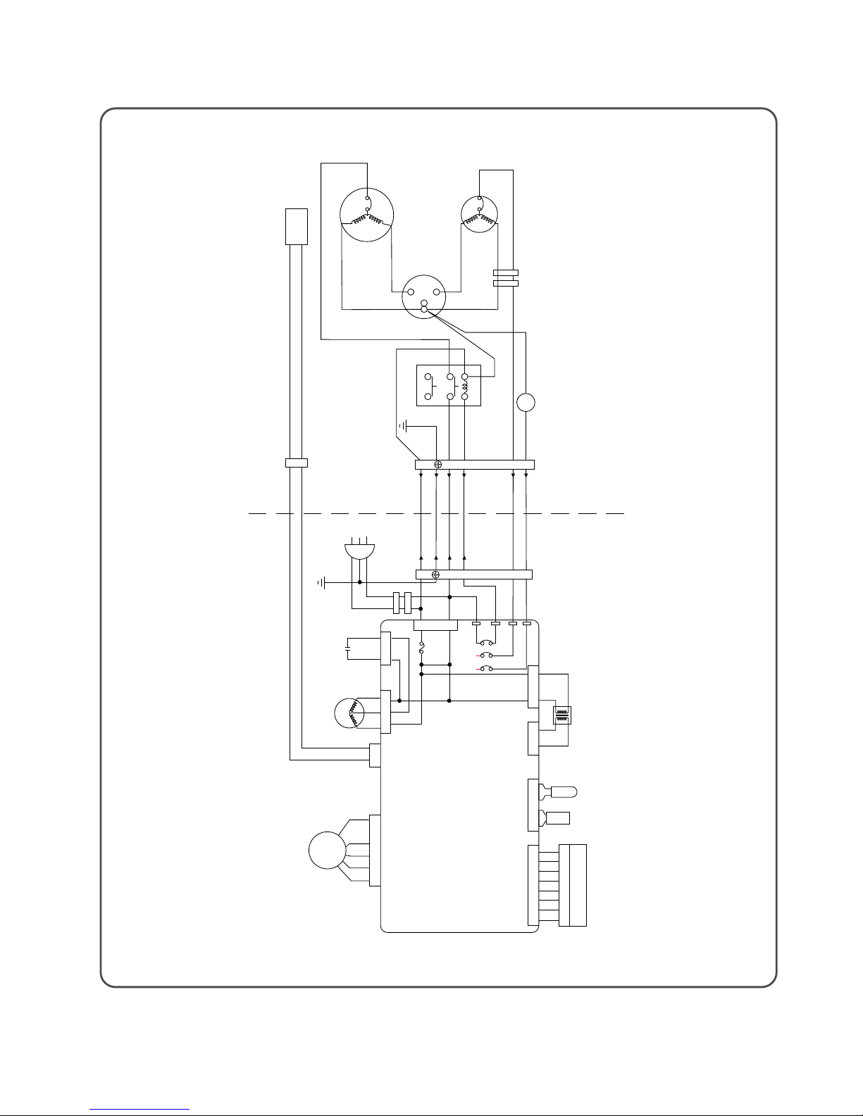
4. WIRING DIAGRAM
* DSA-240L-R
Y
N
L
Y
N
L
FAN MOTOR
BLK
RED
ORG
H
S
S
R
C
C
CAPACITOR DUAL
FAN
HERM
RED
BRN
BRN
OUTDOOR INDOOR
RED
POWER RELAY
RA TH. : ROOM AIR THERMISTOR
IDC TH. : INDOOR COIL THERMISTOR
RA TH. : ROOM AIR THERMISTOR
IDC TH. : INDOOR COIL THERMISTOR
FAN MOTOR
CAPACITOR
INDOOR
FAN MOTOR
SWING MOTOR
BLU
WHT
YEL/GRN
RED
BLU
YEL/GRN
BRN
RED
BLU
BLU
YEL/GRN
YEL
RED
WHT
RED
RED
RA
TH.
IDC
LED PCB
1123456 7
TH.
BLK
PCB TRANS
BLU
RL1
CN1
BLU
BRN
FUSE
BLK
RED
CN4 CN3
CN2 CN6 CN9 CN1
CN13
R
C
S
ORG BLU
RED
ORG
YEL
PNK
BLU
BRN
BRN
YEL/GRN
CONTROL PCB
POWER
CORD
1
8
4
0
6
2
BLU
COMPRESSOR
18
* DSA-240LH-R
BLK
BLK
2
1
Y
N
L
BLK BLK
INDOOR
TERMDNAL
BLOCK
BLK
BLK
4 WAY
PCB TRANS
CN2 CN6 CN3 CN11
CN13
CONTROL PCB
OUTDOOR INDOOR
CN10
CN4 CN3
WHT
WHT
WHT
RED
RED DGR BRN
RED
RED
RA
TH
IDC
TH.
COMP
RL1 RL2 RL3
YEL/GRN
BLK
WHT
H
S
S
R
C
ORG
RED
RED
RED
BRN
OUTDOOR
TERMDNAL
BLOCK
1
3
4
6
5
2
BLU
BLU
WHT
YEL/GRN
YEL/GRN
RED
BRN
BRN
BRN
POWER
CORD
BLU
BLU
WHT
BLU
RED
RED
ORG
YEL
PNK
BLU
GRN
YEL
GRY
BRN
BLK
FUSE
CN1
BLU
YEL/GRN
YEL BLK
R
SC
FAN MOTOR
CAPACITOR
INDOOR
FAN MOTOR
YEL/GRN
YEL/GRN
POWER RELAY
BRN
BRN
RATH: ROOM AIR THERMSTOR
IDC TH: INDOOR COIL THERMSTOR
ODC TH: OUTDOOR COIL THERMSTOR
RATH: ROOM AIR THERMSTOR
IDC TH: INDOOR COIL THERMSTOR
ODC TH: OUTDOOR COIL THERMSTOR
BLU
ODC TH
FAN
HERN
FAN MOTOR
CAPACITOR DRAL
COMPRESSOR
RED
4W
2
1
Y
N
L
12345678
LED PCB
19
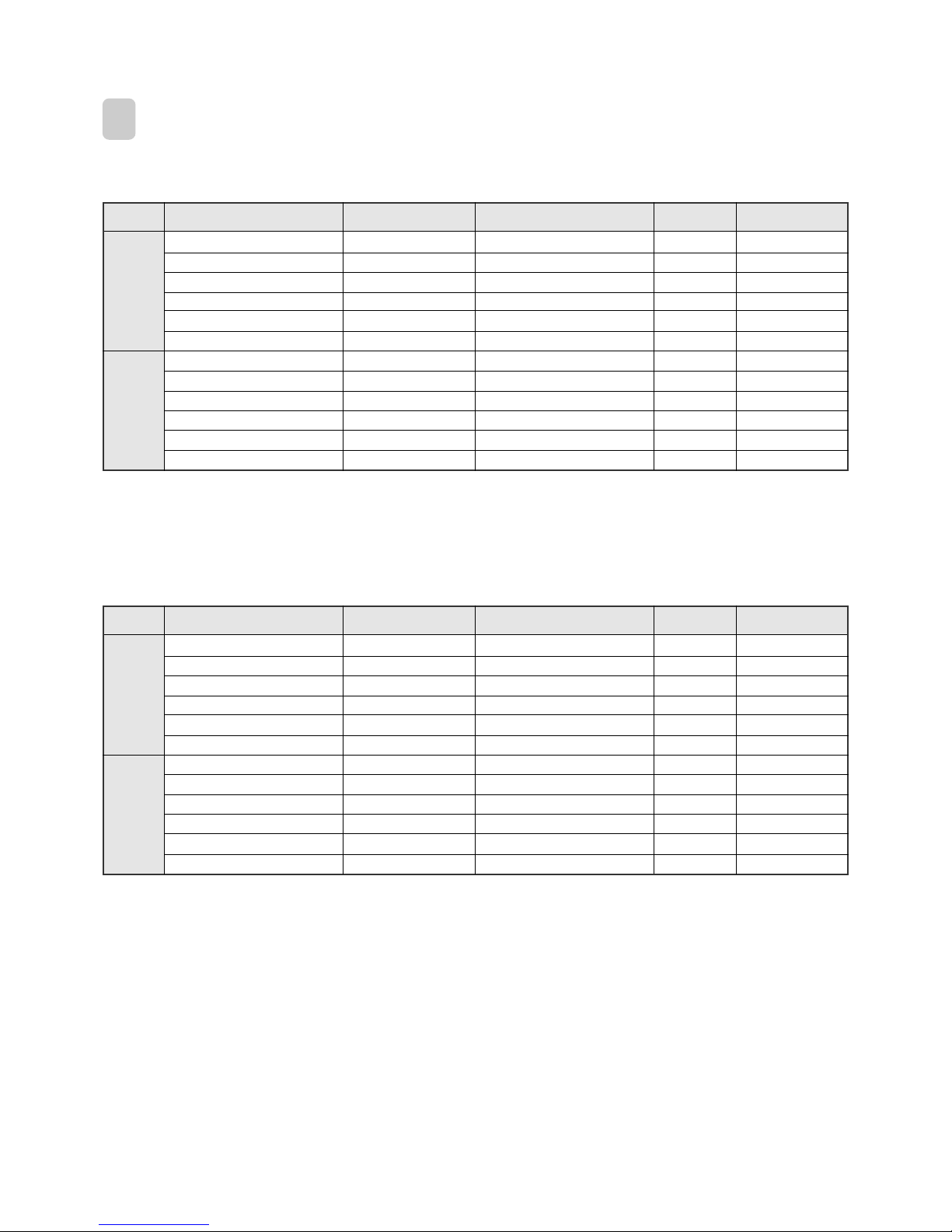
1
MAIN ELECTRIC PARTS
* DSA-240L-R
PART NAME PART CODE SPEC. QUANTITY REMARK
Fan Motor 3108007500 IC-9430DWKG7A 1
Fan Motor Capacitor 3106902400 2.0uF 400VAC 1
Fuse 5FVLB3152L 250V 3.15A 1
Transformer 5EPV050120 230V/50Hz 1
Stepping Motor 3108007600 GSP-24RW-062 1
Terminal Block 3108912320 SN-DBW-062 1
Compressor 3100068201 AWG-5530EXC 1
Fan Motor 3108007400 OSME986DERC 230/50 1
Dual Capacitor 3109508100 5/45µF 400VAC 1
Terminal Block 3108912320 SN-DBW-4P 1
Reversing Valve 3105400310 CHV-0201 SAGINDMIYA 1
Solenoid coil 3109700110 CHV-01AJ506B1 1
Outdoor
Unit
Indoor
Unit
* DSA-240LH-R
PART NAME PART CODE SPEC. QUANTITY REMARK
Fan Motor 3108007500 IC-9430DWKG7A 1
Fan Motor Capacitor 3106902400 2.0uF 400VAC 1
Fuse 5FVLB3152L 250V 3.15A 1
Transformer 5EPV050120 230V/50Hz 1
Stepping Motor 3108007600 GSP-24RW-062 1
Terminal Block 3108912320 SN-DBW-062 1
Compressor 3100068201 AWG-5530EXC 1
Fan Motor 3108007400 OSME986DERC 230/50 1
Dual Capacitor 3109508100 5/45µF 400VAC 1
Terminal Block 3108912320 SN-DBW-4P 1
Reversing Valve 3105400310 CHV-0201 SAGINDMIYA 1
Solenoid coil 3109700110 CHV-01AJ506B1 1
Outdoor
Unit
Indoor
Unit
 Loading...